JP6412505B2 - Steerable guidewire and method of use - Google Patents
Steerable guidewire and method of use Download PDFInfo
- Publication number
- JP6412505B2 JP6412505B2 JP2015545833A JP2015545833A JP6412505B2 JP 6412505 B2 JP6412505 B2 JP 6412505B2 JP 2015545833 A JP2015545833 A JP 2015545833A JP 2015545833 A JP2015545833 A JP 2015545833A JP 6412505 B2 JP6412505 B2 JP 6412505B2
- Authority
- JP
- Japan
- Prior art keywords
- outer tube
- inner tube
- tube
- rod
- distal end
- Prior art date
- Legal status (The legal status is an assumption and is not a legal conclusion. Google has not performed a legal analysis and makes no representation as to the accuracy of the status listed.)
- Active
Links
Images


Classifications
-
- A—HUMAN NECESSITIES
- A61—MEDICAL OR VETERINARY SCIENCE; HYGIENE
- A61M—DEVICES FOR INTRODUCING MEDIA INTO, OR ONTO, THE BODY; DEVICES FOR TRANSDUCING BODY MEDIA OR FOR TAKING MEDIA FROM THE BODY; DEVICES FOR PRODUCING OR ENDING SLEEP OR STUPOR
- A61M25/00—Catheters; Hollow probes
- A61M25/01—Introducing, guiding, advancing, emplacing or holding catheters
- A61M25/09—Guide wires
- A61M25/09016—Guide wires with mandrils
- A61M25/09025—Guide wires with mandrils with sliding mandrils
-
- A—HUMAN NECESSITIES
- A61—MEDICAL OR VETERINARY SCIENCE; HYGIENE
- A61B—DIAGNOSIS; SURGERY; IDENTIFICATION
- A61B17/00—Surgical instruments, devices or methods, e.g. tourniquets
- A61B17/32—Surgical cutting instruments
- A61B17/3205—Excision instruments
- A61B17/32053—Punch like cutting instruments, e.g. using a cylindrical or oval knife
-
- A—HUMAN NECESSITIES
- A61—MEDICAL OR VETERINARY SCIENCE; HYGIENE
- A61B—DIAGNOSIS; SURGERY; IDENTIFICATION
- A61B17/00—Surgical instruments, devices or methods, e.g. tourniquets
- A61B17/34—Trocars; Puncturing needles
- A61B17/3417—Details of tips or shafts, e.g. grooves, expandable, bendable; Multiple coaxial sliding cannulas, e.g. for dilating
-
- A—HUMAN NECESSITIES
- A61—MEDICAL OR VETERINARY SCIENCE; HYGIENE
- A61B—DIAGNOSIS; SURGERY; IDENTIFICATION
- A61B17/00—Surgical instruments, devices or methods, e.g. tourniquets
- A61B17/34—Trocars; Puncturing needles
- A61B17/3478—Endoscopic needles, e.g. for infusion
-
- A—HUMAN NECESSITIES
- A61—MEDICAL OR VETERINARY SCIENCE; HYGIENE
- A61B—DIAGNOSIS; SURGERY; IDENTIFICATION
- A61B17/00—Surgical instruments, devices or methods, e.g. tourniquets
- A61B17/34—Trocars; Puncturing needles
- A61B17/3494—Trocars; Puncturing needles with safety means for protection against accidental cutting or pricking, e.g. limiting insertion depth, pressure sensors
- A61B17/3496—Protecting sleeves or inner probes; Retractable tips
-
- A—HUMAN NECESSITIES
- A61—MEDICAL OR VETERINARY SCIENCE; HYGIENE
- A61M—DEVICES FOR INTRODUCING MEDIA INTO, OR ONTO, THE BODY; DEVICES FOR TRANSDUCING BODY MEDIA OR FOR TAKING MEDIA FROM THE BODY; DEVICES FOR PRODUCING OR ENDING SLEEP OR STUPOR
- A61M25/00—Catheters; Hollow probes
- A61M25/01—Introducing, guiding, advancing, emplacing or holding catheters
- A61M25/09—Guide wires
- A61M25/09041—Mechanisms for insertion of guide wires
-
- A—HUMAN NECESSITIES
- A61—MEDICAL OR VETERINARY SCIENCE; HYGIENE
- A61B—DIAGNOSIS; SURGERY; IDENTIFICATION
- A61B17/00—Surgical instruments, devices or methods, e.g. tourniquets
- A61B17/00234—Surgical instruments, devices or methods, e.g. tourniquets for minimally invasive surgery
- A61B2017/00238—Type of minimally invasive operation
- A61B2017/00243—Type of minimally invasive operation cardiac
- A61B2017/00247—Making holes in the wall of the heart, e.g. laser Myocardial revascularization
-
- A—HUMAN NECESSITIES
- A61—MEDICAL OR VETERINARY SCIENCE; HYGIENE
- A61B—DIAGNOSIS; SURGERY; IDENTIFICATION
- A61B17/00—Surgical instruments, devices or methods, e.g. tourniquets
- A61B17/00234—Surgical instruments, devices or methods, e.g. tourniquets for minimally invasive surgery
- A61B2017/00292—Surgical instruments, devices or methods, e.g. tourniquets for minimally invasive surgery mounted on or guided by flexible, e.g. catheter-like, means
- A61B2017/003—Steerable
- A61B2017/00305—Constructional details of the flexible means
- A61B2017/00309—Cut-outs or slits
-
- A—HUMAN NECESSITIES
- A61—MEDICAL OR VETERINARY SCIENCE; HYGIENE
- A61B—DIAGNOSIS; SURGERY; IDENTIFICATION
- A61B17/00—Surgical instruments, devices or methods, e.g. tourniquets
- A61B17/00234—Surgical instruments, devices or methods, e.g. tourniquets for minimally invasive surgery
- A61B2017/00292—Surgical instruments, devices or methods, e.g. tourniquets for minimally invasive surgery mounted on or guided by flexible, e.g. catheter-like, means
- A61B2017/003—Steerable
- A61B2017/00318—Steering mechanisms
-
- A—HUMAN NECESSITIES
- A61—MEDICAL OR VETERINARY SCIENCE; HYGIENE
- A61M—DEVICES FOR INTRODUCING MEDIA INTO, OR ONTO, THE BODY; DEVICES FOR TRANSDUCING BODY MEDIA OR FOR TAKING MEDIA FROM THE BODY; DEVICES FOR PRODUCING OR ENDING SLEEP OR STUPOR
- A61M25/00—Catheters; Hollow probes
- A61M25/01—Introducing, guiding, advancing, emplacing or holding catheters
- A61M25/09—Guide wires
- A61M2025/09116—Design of handles or shafts or gripping surfaces thereof for manipulating guide wires
-
- A—HUMAN NECESSITIES
- A61—MEDICAL OR VETERINARY SCIENCE; HYGIENE
- A61M—DEVICES FOR INTRODUCING MEDIA INTO, OR ONTO, THE BODY; DEVICES FOR TRANSDUCING BODY MEDIA OR FOR TAKING MEDIA FROM THE BODY; DEVICES FOR PRODUCING OR ENDING SLEEP OR STUPOR
- A61M25/00—Catheters; Hollow probes
- A61M25/01—Introducing, guiding, advancing, emplacing or holding catheters
- A61M25/09—Guide wires
- A61M2025/09175—Guide wires having specific characteristics at the distal tip
-
- A—HUMAN NECESSITIES
- A61—MEDICAL OR VETERINARY SCIENCE; HYGIENE
- A61M—DEVICES FOR INTRODUCING MEDIA INTO, OR ONTO, THE BODY; DEVICES FOR TRANSDUCING BODY MEDIA OR FOR TAKING MEDIA FROM THE BODY; DEVICES FOR PRODUCING OR ENDING SLEEP OR STUPOR
- A61M25/00—Catheters; Hollow probes
- A61M25/01—Introducing, guiding, advancing, emplacing or holding catheters
- A61M25/06—Body-piercing guide needles or the like
- A61M25/0662—Guide tubes
-
- A—HUMAN NECESSITIES
- A61—MEDICAL OR VETERINARY SCIENCE; HYGIENE
- A61M—DEVICES FOR INTRODUCING MEDIA INTO, OR ONTO, THE BODY; DEVICES FOR TRANSDUCING BODY MEDIA OR FOR TAKING MEDIA FROM THE BODY; DEVICES FOR PRODUCING OR ENDING SLEEP OR STUPOR
- A61M25/00—Catheters; Hollow probes
- A61M25/01—Introducing, guiding, advancing, emplacing or holding catheters
- A61M25/09—Guide wires
- A61M25/09016—Guide wires with mandrils
- A61M25/09033—Guide wires with mandrils with fixed mandrils, e.g. mandrils fixed to tip; Tensionable wires
-
- A—HUMAN NECESSITIES
- A61—MEDICAL OR VETERINARY SCIENCE; HYGIENE
- A61M—DEVICES FOR INTRODUCING MEDIA INTO, OR ONTO, THE BODY; DEVICES FOR TRANSDUCING BODY MEDIA OR FOR TAKING MEDIA FROM THE BODY; DEVICES FOR PRODUCING OR ENDING SLEEP OR STUPOR
- A61M29/00—Dilators with or without means for introducing media, e.g. remedies
Landscapes
- Health & Medical Sciences (AREA)
- Life Sciences & Earth Sciences (AREA)
- Surgery (AREA)
- Veterinary Medicine (AREA)
- General Health & Medical Sciences (AREA)
- Public Health (AREA)
- Biomedical Technology (AREA)
- Heart & Thoracic Surgery (AREA)
- Engineering & Computer Science (AREA)
- Animal Behavior & Ethology (AREA)
- Nuclear Medicine, Radiotherapy & Molecular Imaging (AREA)
- Medical Informatics (AREA)
- Molecular Biology (AREA)
- Hematology (AREA)
- Anesthesiology (AREA)
- Pulmonology (AREA)
- Biophysics (AREA)
- Pathology (AREA)
- Media Introduction/Drainage Providing Device (AREA)
Description
本願は、2013年1月25日に出願された米国特許出願第13/750,689号および2012年12月6日に出願された米国仮特許出願第61/734,297号の優先権を主張し、それぞれの全容を本明細書中で参考として援用する。 This application claims the priority of US Patent Application No. 13 / 750,689 filed on January 25, 2013 and US Provisional Patent Application No. 61 / 734,297 filed on December 6, 2012. The entire contents of each are incorporated herein by reference.
以下に記載の本発明は、ガイドワイヤの分野に関する。 The invention described below relates to the field of guidewires.
心臓アクセスに向けた特定の侵襲処理の間、患者には静脈または動脈のアクセスポイントを通じてカテーテルが挿入される。カテーテルは、静脈切開または経皮アクセス法で作られ得るアクセスポイントを通じて、心臓または心臓血管系の他の領域に送られる。カテーテルは、心臓、脳血管、または心臓血管系の他の領域内の目的地に送られ得る。この送りは、典型的には、セルジンガー法と呼ばれこともある経皮アクセス法を用いて実施される。他の血管アクセス法では切開術アクセスが必要とされる。どちらの場合でも、経皮的にまたは切開法によりガイドワイヤを脈管構造内に進める。ガイドワイヤは、それに沿ってカテーテルを患者内の目的部位まで送る際の追跡システムの働きをする。ガイドワイヤは、経カテーテル、血管内、または血管アクセス、ならびに経皮、腹腔鏡、胸腔鏡、および筋肉内アクセス等の処置などに使用することができる。 During a particular invasive procedure for cardiac access, the patient is inserted with a catheter through a venous or arterial access point. The catheter is routed to the heart or other areas of the cardiovascular system through access points that can be made by phlebotomy or percutaneous access. The catheter can be delivered to a destination in the heart, cerebrovascular, or other area of the cardiovascular system. This feed is typically performed using a transdermal access method, sometimes referred to as the Seldinger method. Other vascular access methods require incision access. In either case, the guide wire is advanced into the vasculature percutaneously or by incision. The guide wire serves as a tracking system in delivering the catheter along it to the target site within the patient. Guidewires can be used for transcatheter, intravascular or vascular access and procedures such as percutaneous, laparoscopic, thoracoscopic, and intramuscular access.
予め曲げられたガイドワイヤは、ガイドカテーテルと併用で脈管構造内を進み、該脈管構造内で二又または他の方向逸脱が生じると、ガイドカテーテルの予め曲げられた遠位先端を正しい方向に向けることを可能とする。 A pre-bent guidewire travels through the vasculature in combination with a guide catheter, and when a bifurcation or other directional deviation occurs in the vasculature, the pre-bend distal tip of the guide catheter is oriented in the correct direction. It is possible to turn to.
開示されているこのガイドワイヤは、関節的動作、操縦、屈曲、偏向、もしくはそれ以外に軸線を外れて制御されることが可能であって、脈管または身体組織内での追跡や、中空器官内の特定の目的地内への移動を可能にする。この関節的動作または操縦は、一切のガイドカテーテルとの相互作用なしで実施することができる。 This disclosed guide wire can be controlled off-axis for articulation, steering, bending, deflection, or otherwise, tracking within a vessel or body tissue, or hollow organ Allows movement into specific destinations within. This articulation or steering can be performed without any interaction with the guide catheter.
ガイドワイヤ・デバイスの遠位領域の操縦性、偏向、または関節的動作は、同軸に配置され、ガイドワイヤの遠位領域で半径方向に一緒に束縛されている内管と外管とを用いて実現することができる。
内管の外径は、外管の内径と精密公差で嵌合しているが、内管は外管に対し相対的にこれらの管の縦軸線方向に自由に平行移動する。このように、縦軸線方向の平行移動運動のみが、関節的動作の発生に用いられる。
内管は遠位端に近接した領域を改変されて、内管は概ね縦方向に2つ以上の要素に分割され、弱化され、または分裂される。内管のこれら分割要素の一部分だけが、その近位端を、内管のより近位の部分に取り付けられる。近位端が取り付けられていない内管の要素は、それらの遠位端近くを、近位端も取り付けられている内管の部分に随意に取り付けられ得る。
外管は、一般に横方向または半径方向に向けられた溝穴または間隙を切ることによって可撓性にされるが、角度を有するかまたは外管の縦軸線方向の何らかの突起があり得る。これらの横方向溝穴は外管を完全に貫通してはいないので、外管に突起のある背骨が形成される。外管は、遠位領域の1つまたは複数の側部に沿って、コイル巻きまたは巻回の間に有限の間隔を有する螺旋またはコイルとして形成され得る。
バックボーンまたは一連の止めデバイスを随意で加えて、この構成における巻回またはコイルの一側部の縦方向の圧縮または伸長を防止することができる。本明細書では、バックボーンまたは固定柱を有するコイル構造の実施形態は、外管の遠位要素が複数の切れ目、横方向溝穴等によって可撓性とされている実施形態と交換可能に用いられる。
Steerability, deflection, or articulation of the distal region of the guidewire device is achieved using an inner tube and an outer tube that are arranged coaxially and are constrained together radially in the distal region of the guidewire Can be realized.
The outer diameters of the inner pipes are fitted to the inner diameters of the outer pipes with close tolerances, but the inner pipes freely translate in the longitudinal direction of these pipes relative to the outer pipes. In this way, only the translational movement in the direction of the vertical axis is used for the generation of articulation.
The inner tube is modified in the region proximate to the distal end so that the inner tube is split, weakened, or split into two or more elements generally longitudinally. Only a portion of these split elements of the inner tube has its proximal end attached to the more proximal portion of the inner tube. Elements of the inner tube that are not attached to the proximal end can optionally be attached near their distal end to the portion of the inner tube that is also attached to the proximal end.
The outer tube is made flexible by cutting slots or gaps that are generally oriented transversely or radially, but may have an angle or some protrusion in the longitudinal direction of the outer tube. Since these transverse slots do not penetrate the outer tube completely, a spine with a protrusion on the outer tube is formed. The outer tube may be formed as a helix or coil with a finite spacing between coil turns or turns along one or more sides of the distal region.
A backbone or series of stop devices can optionally be added to prevent longitudinal compression or expansion of the turns or one side of the coil in this configuration. Herein, embodiments of the coil structure having a backbone or fixed column are used interchangeably with embodiments in which the distal element of the outer tube is made flexible by a plurality of cuts, transverse slots, etc. .
内管は、外管の横方向溝穴よりも遠位の領域(外管の可撓性領域)で外管に取り付けられ得る。外管に取り付けられる内管の部分は、近位端が内管のより近位の部分に取り付けられている、分裂した内管の部分である。内管は、非対称の遠位端を有する構成であり得、好ましくは該遠位端で長さ方向に分裂している。この分裂は、一側部で内管の側部に向けて貫通して半径方向に移行するように向けられる。この構成により、内管に接続側部と非接続側部とができる。非接続側部は、ブリッジによって遠位端近くで接続側部に取り付けられ得る。 The inner tube can be attached to the outer tube in a region distal to the lateral slot of the outer tube (flexible region of the outer tube). The portion of the inner tube that is attached to the outer tube is the portion of the inner tube that is split, with the proximal end attached to the more proximal portion of the inner tube. The inner tube may be configured with an asymmetrical distal end, preferably split longitudinally at the distal end. This split is directed to penetrate radially toward the side of the inner tube at one side. With this configuration, the inner pipe can be connected and disconnected. The unconnected side can be attached to the connected side near the distal end by a bridge.
このように、複数の(2つ以上の)入れ子式の半径方向に束縛されている実質的に同軸状の軸方向に平行移動する管を用いて関節的動作が生じ、第1の管は一側部が弱化されて可撓性を増し、最終的な曲率および形状を限定し、第2の管は実質的に縦方向に分裂され、第1の管も弱化している領域内で一側部が中断されている。管は両方とも実質的に所定位置にあって、フープ強度、柱強度、よじれ抵抗性、および複数の管内に存在する切れ目または溝穴など個々の構造の方向性を維持している。 Thus, articulation occurs using a plurality of (two or more) nested radially constrained substantially coaxially axially translating tubes, the first tube being one One side in the region where the sides are weakened to increase flexibility, limiting the final curvature and shape, the second tube is split substantially longitudinally and the first tube is also weakened Department has been suspended. Both tubes are substantially in place, maintaining hoop strength, column strength, kink resistance, and orientation of individual structures such as cuts or slots present in multiple tubes.
ガイドワイヤの近位要素は、異なる屈曲性を有する円筒状管から製造された、1つまたは複数の中間管とともに標準の無傷円筒状構成の外管で構成され得、円筒状管は、該管に切られた可撓性を向上させるための溝穴、閉じたコイル、編まれた巻回、または巻回の間が多少開いているコイルを有する。内管の近位領域は、中実の構造体か、または管ではなくワイヤに取り付けられ得る。 The proximal element of the guidewire can be composed of an outer tube of a standard intact cylindrical configuration with one or more intermediate tubes made from cylindrical tubes having different bends, the cylindrical tube being It has a slot, a closed coil, a knitted turn, or a coil that is somewhat open between turns to improve flexibility. The proximal region of the inner tube can be a solid structure or attached to a wire rather than a tube.
操縦可能(ステアブル)ガイドワイヤは、好ましくは約0.010インチから約0.038インチの範囲の直径に製造され得る。剛性および先端形状はさまざまであり得る。ガイドワイヤは、限定ではないが、たとえばしなやかな直線状の先端、J字型に湾曲した先端、およびわずかに湾曲した先端など、非偏向の先端構成とすることができる。
ガイドワイヤの長さは、約50cmから約250cm以上の範囲であり得る。操縦可能ガイドワイヤは、好ましくは、ガイドワイヤに沿わせてロードされるカテーテルの典型的には2倍の長さであり得るので、ユーザーは、カテーテル全体をガイドワイヤに沿わせて挿入した状態で、ガイドワイヤの近位端と遠位端の両方を把持したままでいられる。
ガイドカテーテルをガイドワイヤと併用して、いくらかの操縦性を得ることができる。たとえば、湾曲した先端を有するガイドワイヤをガイドカテーテル内に引き込んで直線状の構成を得てから、ガイドカテーテルの外部に進めて湾曲させ、脈管または身体管腔内へと進め、次いでガイドカテーテルの操作が次に必要になるまでガイドワイヤに沿って進められる。先端の湾曲は、予め湾曲させておくのではなく、その場で関節的動作によって生じさせることができる。
The steerable guidewire can be manufactured to a diameter preferably ranging from about 0.010 inches to about 0.038 inches. The stiffness and tip shape can vary. The guidewire can be a non-deflecting tip configuration such as, but not limited to, a supple linear tip, a J-curved tip, and a slightly curved tip.
The length of the guidewire can range from about 50 cm to about 250 cm or more. The steerable guidewire may preferably be twice as long as a catheter loaded along the guidewire so that the user can insert the entire catheter along the guidewire. , Both the proximal and distal ends of the guidewire can be held.
Some maneuverability can be obtained using a guide catheter in conjunction with a guidewire. For example, a guide wire having a curved tip is drawn into a guide catheter to obtain a linear configuration, then advanced out of the guide catheter to bend and advanced into a vessel or body lumen, and then the guide catheter Proceed along the guidewire until the next operation is required. The curvature of the tip can be caused by articulation in place rather than precurved.
操縦可能ガイドワイヤは、腔内、経血管、または血管内に配置される操縦可能ガイドワイヤであり、その遠位端がその縦軸線から離れる方向に内に偏向できるか、または関節的動作することができる。操縦可能ガイドワイヤは、一般にはステンレス鋼、ニチノール等から製造され、外管、内管、および遠位関節的動作領域を備える。偏向または関節的動作の機構は、操縦可能ガイドワイヤと一体化されている。操縦可能ガイドワイヤは、哺乳動物患者およびヒト患者を含む動物に有用であり、身体管腔または他の身体構造を通じて送られて最終目的地に達する。
ガイドワイヤは、カテーテル留置のガイドとして用いられるワイヤ、複合ワイヤまたはスプリングである。ガイドワイヤは、近位端側から押されて遠位先端を患者の脈管構造内に通すことができる十分な柱強度によって特徴づけられる点において、カテーテルと連携するパンチ、送達ワイヤなどの他の細長い構造物とは構造的に異なるが、遠位先端は血管壁によって偏向される十分な可撓性があるので、通過中に血管を変形させたり穿孔したり傷つけたりすることなく血管壁に接する。
心臓血管用途の典型的なガイドワイヤの直径範囲は、0.010インチから0.018インチから0.025インチであり、長さ範囲は100cmから300cmであり、先端剛性は、閉塞のない血管へのアクセスでは1グラムから10グラムであり、閉塞したまたは狭窄のある血管を渡る場合は10グラムから30グラムである。
先端剛性は、先端を45%偏向させるのに必要な力/重量の量によって測定される。末梢ガイドワイヤの直径はもっと大きい(0.032インチ、0.038インチの範囲であり、先端剛性も高い場合がある)。好ましくは、本明細書に記載のように作られた可撓性ガイドワイヤは、グラムで測定すると1グラムから30グラムの先端剛性を有する。
冠状動脈アクセスなどの一部の用途では、先端部は、ガイドワイヤの主要部よりもしなやか(低剛性)であるが、大動脈アクセスなどの別の用途では、先端部と主要部とはほぼ同じ剛性を有し得る。しなやかな先端部が設けられる場合は、ガイドワイヤの最遠位端のところで0.5cmから10cm、好ましくは1センチから5センチ延在し得る。
A steerable guidewire is a steerable guidewire that is placed intraluminally, transvascularly, or within a blood vessel, whose distal end can be deflected inwardly away from its longitudinal axis, or articulated Can do. The steerable guidewire is typically manufactured from stainless steel, nitinol, etc., and includes an outer tube, an inner tube, and a distal articulation region. The deflection or articulation mechanism is integrated with the steerable guidewire. Steerable guidewires are useful for animals, including mammalian patients and human patients, and are routed through body lumens or other body structures to reach their final destination.
The guide wire is a wire, a composite wire or a spring used as a guide for catheter placement. The guidewire is characterized by sufficient column strength that can be pushed from the proximal end side to allow the distal tip to pass through the patient's vasculature, and other guide punches, delivery wires, etc. Although structurally different from elongate structures, the distal tip is sufficiently flexible to be deflected by the vessel wall so that it will contact the vessel wall without deforming, piercing, or damaging the vessel during passage .
The typical guidewire diameter range for cardiovascular applications is 0.010 inches to 0.018 inches to 0.025 inches, the length range is 100 cm to 300 cm, and the tip stiffness is to an unoccluded blood vessel. 1 to 10 grams for access and 10 to 30 grams for crossing occluded or stenotic blood vessels.
Tip stiffness is measured by the amount of force / weight required to deflect the tip by 45%. The diameter of the peripheral guidewire is much larger (in the range of 0.032 inch, 0.038 inch and the tip stiffness may be higher). Preferably, a flexible guidewire made as described herein has a tip stiffness of 1 to 30 grams measured in grams.
In some applications, such as coronary access, the tip is supple (less rigid) than the main part of the guidewire, but in other applications, such as aortic access, the tip and main part are approximately the same stiffness Can have. Where a supple tip is provided, it may extend from 0.5 cm to 10 cm, preferably from 1 cm to 5 cm, at the most distal end of the guidewire.
ガイドワイヤの主要部およびガイドワイヤ先端部の剛性は、曲げ弾性率(屈曲弾性率)との関係で表すこともできる。好ましくは、本明細書に記載のように作られた可撓性ガイドワイヤは、主要部の方向にある範囲の、たとえば8ギガパスカルから10ギガパスカルの曲げ弾性率を有することになる。
しなやかな先端部が設けられる場合は、しなやかな先端部は主要部の100%から10%の範囲の、たとえば0.8ギガパスカルから10ギガパスカルの曲げ弾性率を有することになる。「剛性」ガイドワイヤは、約16ギガパスカルから20ギガパスカルの曲げ弾性率を有し得、超剛性ガイドワイヤは28ギガパスカルから32ギガパスカルの曲げ弾性率を有し得、超剛性ガイドワイヤは50ギガパスカルから70ギガパスカルの曲げ弾性率を有し得る。このような高曲げ弾性率のガイドワイヤの先端部は、ガイドワイヤの主要部に対し「しなやか」な場合は、主要部の10%から90%の曲げ弾性率であり得る。
これらの構造的特徴は、パンチ、超音波カテーテル、およびシースなしでの患者脈管構造内の移動に適していない、脈管内を通ってカテーテルを案内するのに適していない他の構造体などの他の構造体と、ガイドワイヤとを区別するものである。
The rigidity of the main portion of the guide wire and the tip end portion of the guide wire can also be expressed by the relationship with the bending elastic modulus (flexural elastic modulus). Preferably, a flexible guidewire made as described herein will have a flexural modulus in a range in the direction of the main portion, for example, 8 gigapascals to 10 gigapascals.
If a supple tip is provided, the supple tip will have a flexural modulus in the range of 100% to 10% of the main part, for example 0.8 gigapascal to 10 gigapascal. A “rigid” guidewire may have a flexural modulus of about 16 gigapascals to 20 gigapascals, a superrigid guidewire may have a flexural modulus of 28 gigapascals to 32 gigapascals, It can have a flexural modulus of 50 to 70 gigapascals. The tip portion of the guide wire having such a high flexural modulus can have a flexural modulus of 10% to 90% of the main portion when “flexible” with respect to the main portion of the guide wire.
These structural features include punches, ultrasound catheters, and other structures that are not suitable for movement within the patient vasculature without a sheath, and are not suitable for guiding the catheter through the vessel. Different structures are distinguished from guide wires.
操縦可能ガイドワイヤは、内管および外管を備える。操縦可能ガイドワイヤは、取り外し可能もしくは取り外し不可能であり得るスタイレットまたはオブチュレータも備えることができる。操縦可能ガイドワイヤはさらに、近位端に、操縦可能ガイドワイヤの把持を可能にするハブ、ならびに遠位端での関節的動作を制御する特徴つまり制御機構を備える。そのような特徴は、制御つまみ、ハンドル、レバー等で構成され得る。
近位端はさらに、随意で雌ルアーまたはルアーロック・ポートまたは止血バルブを末端に設けることができ、これらは圧力モニター線、色素注入線、真空線、それらの組合せ等の装着に適している。
操縦可能ガイドワイヤは、ルアーまたはルアーロック・ポートに機能的に取り付けられた中心チャネルを備えることができ、該チャネルは、色素注入、物質もしくは流体の投与もしくは回収、圧力モニタリング等に便利である。カテーテルが、(オーバーザワイヤ法で)ガイドワイヤの近位端から始まってガイドワイヤに沿って進められることは有益であり得る。
オーバーザワイヤ式に用いるために、遠位の偏向を制御する機構を備えるハブは、好ましくはガイドワイヤから取り外し可能であり、カテーテルがガイドワイヤの近位端を通過して進められると、ガイドワイヤに解放可能または解放不可能に取り付けられ得る。
The steerable guidewire includes an inner tube and an outer tube. The steerable guidewire can also comprise a stylet or obturator that can be removable or non-removable. The steerable guidewire further comprises a hub at the proximal end that allows grasping of the steerable guidewire and a feature or control mechanism that controls articulation at the distal end. Such features may consist of control knobs, handles, levers and the like.
The proximal end may optionally further be provided with a female luer or luer lock port or hemostasis valve, which is suitable for mounting pressure monitor lines, dye injection lines, vacuum lines, combinations thereof, and the like.
The steerable guidewire can comprise a central channel operatively attached to the luer or luer lock port, which is convenient for dye injection, substance or fluid administration or recovery, pressure monitoring, and the like. It may be beneficial for the catheter to be advanced along the guidewire starting from the proximal end of the guidewire (in an over-the-wire manner).
For over-the-wire use, the hub with a mechanism for controlling distal deflection is preferably removable from the guidewire, and when the catheter is advanced past the proximal end of the guidewire, Can be releasably or non-releasably attached.
操縦可能ガイドワイヤは、近位端から遠位端までほぼ直線状であるように製造される。操縦可能ガイドワイヤの近位端で制御機構が操作されると、操縦可能ガイドワイヤの遠位領域はその縦軸線から離れて屈曲または湾曲する。この屈曲、操縦、偏向、または関節的動作領域は、操縦可能ガイドワイヤの遠位端近くに位置し、可撓性領域または構造であり得、操縦可能ガイドワイヤの近位端の制御ハンドルから可撓性領域よりも遠位の箇所に送られる制御ロッドまたは管状構造体を通じての張力または圧縮下に置かれる。 The steerable guidewire is manufactured to be generally straight from the proximal end to the distal end. When the control mechanism is manipulated at the proximal end of the steerable guidewire, the distal region of the steerable guidewire bends or curves away from its longitudinal axis. This bending, steering, deflection, or articulating region of motion is located near the distal end of the steerable guidewire and can be a flexible region or structure that is accessible from the control handle at the proximal end of the steerable guidewire. It is placed under tension or compression through a control rod or tubular structure that is sent to a location distal to the flexible region.
一使用方法は、中心コアワイヤまたはスタイレットを挿入して、操縦可能ガイドワイヤの遠位端から突出させることを含む。経皮法または静脈切開法を行って、限定ではないが、静脈、動脈、身体の管腔または管といった脈管構造、中空器官、筋系、筋膜、皮膚組織、腹腔、胸腔等などの身体構造への到達する。
通常中空の大径の皮下注射用針であるイントロデューサ、および操縦可能ガイドワイヤが脈管構造内に配置され、操縦可能ガイドワイヤは目的の治療部位の近傍に送られる。イントロデューサはこの時点で、またはガイドワイヤが身体管腔内に導入されたのとほぼ同時に除去できる。
ガイドカテーテルは、好ましくは、テーパー状遠位先端が事前に挿入されている、操縦可能ガイドワイヤに沿って滑り嵌めできるサイズのコアルーメンを有する取り外し可能な中心オブチュレータまたはダイレータと一緒に、操縦可能ガイドワイヤに沿って目的部位に送られる。
操縦可能ガイドワイヤは、ほぼ直線状の構成となるように調節され得る。操縦可能ガイドワイヤは、すでに配置されているカテーテル、シース、イントロデューサ、またはガイドカテーテルの中心ルーメンを通って進められることができる。操縦可能ガイドワイヤは、ほぼ非外傷性の鈍い遠位先端を備える。遠位先端は丸みがあるか、卵形等であり得る。
One method of use involves inserting a central core wire or stylet and projecting it from the distal end of the steerable guidewire. Perform percutaneous or phlebotomy, including but not limited to bodies such as veins, arteries, body lumens or tubes, hollow organs, musculature, fascia, skin tissue, abdominal cavity, chest cavity, etc. Reach the structure.
An introducer, typically a hollow large diameter hypodermic needle, and a steerable guidewire are placed within the vasculature and the steerable guidewire is routed near the intended treatment site. The introducer can be removed at this point, or at approximately the same time as the guidewire is introduced into the body lumen.
The guide catheter is preferably a steerable guide with a removable central obturator or dilator having a core lumen sized to be slip-fit along a steerable guidewire with a pre-inserted tapered distal tip. It is sent to the target site along the wire.
The steerable guidewire can be adjusted to a generally linear configuration. The steerable guidewire can be advanced through the central lumen of an already placed catheter, sheath, introducer, or guide catheter. The steerable guidewire includes a generally atraumatic blunt distal tip. The distal tip can be rounded, oval or the like.
操縦可能ガイドワイヤの遠位端は、および随意でガイドワイヤの本体部も、十分に放射線不透過性なので、蛍光透視法またはX線撮影下ではっきりと観察できる。操縦可能ガイドワイヤは、特にその遠位端近くが、操縦可能ガイドワイヤの、偏向が生じ得る側部について何らかの指標を提供する非対称の放射線不透過性マーカーを有する構成であり得る。操縦可能ガイドワイヤの所在、および遠位端の偏向と曲率の量は、前述の蛍光透視法またはX線撮影、またはMRI、PETスキャン、超音波撮影等などの他の撮影法により観察され制御される。
操縦可能ガイドワイヤの遠位端に1つまたは複数の放射線不透過性マーカーを取り付けて、蛍光透視下の視認性をさらに高めることができる。そのような放射線不透過性マーカーは、限定ではないが、密度の高い鉄金属、タンタル、金、白金、白金・イリジウム等などの材料を含み得る。
The distal end of the steerable guidewire and optionally the body of the guidewire are also sufficiently radiopaque so that they can be clearly observed under fluoroscopy or radiography. The steerable guidewire may be configured with an asymmetric radiopaque marker, particularly near its distal end, that provides some indication of the side of the steerable guidewire that may be deflected. The location of the steerable guidewire and the amount of deflection and curvature of the distal end are observed and controlled by other fluoroscopy methods such as fluoroscopy or radiography as described above, or MRI, PET scan, ultrasonography etc. The
One or more radiopaque markers can be attached to the distal end of the steerable guidewire to further enhance visibility under fluoroscopy. Such radiopaque markers may include, but are not limited to, materials such as dense iron metal, tantalum, gold, platinum, platinum / iridium, and the like.
ガイドワイヤの近位端からの制御下で、遠位先端をさまざまな程度の曲率に偏向させることが実施できる。湾曲は分岐する脈管または脈管の湾曲の方向に向けることができるので、操縦可能ガイドワイヤはその高い柱強度およびトルク伝達性によって脈管内に進められることができる。このときカテーテルのすべての曲率との整合が完了し得る。
蛍光透視、超音波、または他の撮影システム下で正しく配置されると、操縦可能ガイドワイヤの中心ルーメンにその近位端から色素が注入され、操縦可能ガイドワイヤの遠位端から排出されて、ロードマップなどを提供することができる。
この操縦機能は、デバイスを配置するのに非常に有用であり、二又、三又等などの分岐構造をさらに含み得る非常に曲がりくねった脈管または身体管腔において特に有用でもある。
Under control from the proximal end of the guidewire, the distal tip can be deflected to varying degrees of curvature. Because the curvature can be directed in the direction of the branching vessel or vessel curvature, the steerable guidewire can be advanced into the vessel due to its high column strength and torque transferability. At this time, matching with all the curvatures of the catheter can be completed.
When properly positioned under fluoroscopy, ultrasound, or other imaging system, dye is injected into the central lumen of the steerable guidewire from its proximal end and ejected from the distal end of the steerable guidewire, A road map can be provided.
This steering function is very useful for positioning the device, and is also particularly useful in very tortuous vessels or body lumens that may further include bifurcated structures such as bifurcated, trifurcated, etc.
内管、外管、またはその両方が、可撓度を制御するために、その壁に溝穴を設けることができる。溝穴は、「スネークカット」として構成されて、1つまたは複数の背骨を有する一連の肋骨(リブ)を形成することができる。
背骨は、内管、外管、またはその両方の所与の周方向位置で方向付けられ得る。背骨は、一定ではない方向を有することもできる。一部の実施形態では、外管だけに溝穴が設けられる。溝穴は、湾曲が生じる外管の遠位部分内に作られ得る。この距離は、端部の約0.5cmから15cmの範囲であり、好ましくは遠位端の1cmから5cmの範囲である。溝穴の幅は、0.001インチから0.100インチの範囲であり得、好ましい幅は0.003インチから0.010インチであり、さらに好ましくは溝穴の幅は約0.008インチである。
外管は一方向だけに曲がり、反対方向や左右の方向には曲がらないことが望ましい。この操作性を得るために、溝穴を外管の一側部の、たとえば管長さの遠位10cm以内に作ることができ、反対側は溝穴なしの元のままにしておく。およそ0.010インチから0.040インチの幅のおよそ5個から30個の切れ目を作ることができる。
一側部から管径を横切る切れ目の深さは、管径の0.1から0.9の範囲であり得る。好ましくは、切れ目の深さは管径のおよそ0.4から0.6で、切れ目の幅は0.025インチであり得る。
第2の切れ目を管の反対側に作ることができ、この第2の切れ目はおよそ0.005インチ以下である。外管は、まず円弧形に屈曲されてから、溝穴を作られることができるので、管が0.005インチ幅の切れ目へと曲げ戻されると、管は、切れ目と切れ目の間の各管区分がわずかに円弧状かまたは湾曲していても、ほぼ直線状の構成となる。
The inner tube, the outer tube, or both can be slotted in the wall to control flexibility. The slots can be configured as “snake cuts” to form a series of ribs having one or more spines.
The spine can be oriented at a given circumferential location on the inner tube, the outer tube, or both. The spine can also have a non-constant orientation. In some embodiments, only the outer tube is provided with a slot. The slot can be made in the distal portion of the outer tube where the curvature occurs. This distance is in the range of about 0.5 cm to 15 cm at the end and preferably in the range of 1 cm to 5 cm at the distal end. The slot width can range from 0.001 inch to 0.100 inch, with a preferred width of 0.003 inch to 0.010 inch, more preferably a slot width of about 0.008 inch. is there.
It is desirable that the outer tube bends in only one direction and does not bend in the opposite direction or the left-right direction. To obtain this operability, a slot can be made on one side of the outer tube, for example, within 10 cm distal of the tube length, leaving the other side unslotted. Approximately 5 to 30 cuts with a width of approximately 0.010 inches to 0.040 inches can be made.
The depth of the cut across the tube diameter from one side can range from 0.1 to 0.9 of the tube diameter. Preferably, the depth of the cut can be approximately 0.4 to 0.6 of the tube diameter and the width of the cut can be 0.025 inches.
A second cut can be made on the opposite side of the tube, the second cut being approximately 0.005 inches or less. The outer tube can first be bent into an arc and then slotted so that when the tube is bent back into a 0.005 inch wide cut, the tube Even if the tube section is slightly arcuate or curved, it has a substantially linear configuration.
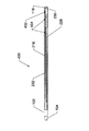
図1Aは、遠位外管102、内側制御管またはロッド104、外側低摩擦コーティング106、中間外管108、近位外管110、さらにハブ本体ルーメン124を備えるハブ本体112、ねじジャッキトラベラー114、制御つまみ116、ガイドワイヤ先端118、内管ロック120、および近位外管ロック122を備える、操縦可能ガイドワイヤ100の側面図を説明する。
FIG. 1A shows a distal
図1Aを参照すると、内側制御管またはロッド(以後、内管と呼ぶ)104の遠位端は、遠位外管102の遠位端に溶接部、接着剤、留め具、固定デバイス等によって取り付けられている。
内側制御管または内管104は、遠位外管102と互いに取り付けられている遠位端を除き、遠位外管102の内部ルーメン内に摺動可能に配置されている。遠位外管102の近位端は、中間外管108の遠位端に溶接部、固定デバイス、接着剤等によって取り付けられている。中間外管108の近位端は、近位外管110の遠位端に溶接部、固定デバイス、接着剤等によって取り付けられている。
外管アセンブリ102、108、110全体を随意の減摩コーティングまたは層106で覆うことができる。ガイドワイヤ先端118またはノーズコーンが内管104、遠位外管102、またはその両方に取り付けられる。ガイドワイヤ先端118は、貫通孔を備えて、その中を通って流体が注入されることや、ガイドワイヤ100の遠位端を越えてスタイレット(図示せず)が進められることを可能にすることができる。制御つまみ116はハブ本体112内で回転して自由に動き、ハブ本体112に縦方向に取り付けられており、これら2つの構成要素は互いに対し相対的に軸方向に移動しない。
ねじジャッキトラベラー114は、ハブ本体112の内部ルーメン124端部の束縛要素内で、ハブ本体112内のルーメン124内を軸方向に移動することができる。ねじジャッキトラベラー114は、ルーメン124内の相補的構造体に当たる丸みのない断面によってルーメン124内でキー止めされて、2つの構成要素112、124の相対的な回転運動を防止する。
ねじジャッキトラベラー114は、制御つまみ116の雌ねじに対し相補的でありそれに嵌る雄ねじを備える。したがって、制御つまみ116が回されると、制御つまみ116はハブ本体112内で縦方向に取り付けられているので、ねじジャッキトラベラー114が軸方向に前方または後方に移動させられる。
Referring to FIG. 1A, the distal end of the inner control tube or rod (hereinafter referred to as the inner tube) 104 is attached to the distal end of the distal
The inner control or
The entire
The
The
ねじジャッキトラベラー114と制御つまみ116のねじ山の間隔は、約16から約64ねじ山/インチ(TPI)の範囲であり得、好ましい範囲は約24TPIから約48TPI、より好ましい範囲は約28TPIから約36TPIである。
The thread spacing between the
ハブアセンブリは、操縦可能ガイドワイヤから取り外し可能であり得るので、操縦可能ガイドワイヤ100の近位端は、ガイドワイヤの中間部分や遠位端と同じ(またはそれよりも小さい)直径または輪郭を保持している。
内部ガイドワイヤルーメンを備えるカテーテル、ガイドカテーテル、イントロデューサ、シース、または他の軸方向に細長い医療デバイスは、操縦可能ガイドワイヤの近位端に滑らかに嵌り、すでに配置されている操縦可能ガイドワイヤに沿って患者体内に進められる。この方法は、カテーテル交換、取替え、入替え等を可能にする。
カテーテルの近位端が操縦可能ガイドワイヤの近位端よりも遠位に位置するまで進められると、ハブアセンブリは操縦可能ガイドワイヤの近位端に解放可能に取り付けられ得、近位端での制御下でガイドワイヤの遠位端が偏向できるようになる。
図1Aで説明しているハブアセンブリは、操縦可能ガイドワイヤの外管110および内管104を固着するための外管ロック122および内管ロック120を提供するので、ハブは取り付けられて、これら2本の管の相対的な軸方向位置を制御する。外管ロック122は、(例示のように)差し込みマウントとして構成され得、または、止めボタン、止めクランプ、ねじロック等を備え得る。
The hub assembly may be removable from the steerable guidewire so that the proximal end of the
A catheter, guide catheter, introducer, sheath, or other axially elongated medical device with an internal guidewire lumen fits smoothly into the proximal end of the steerable guidewire and is placed on the steerable guidewire already in place Along the body of the patient. This method allows for catheter replacement, replacement, replacement, and the like.
When the proximal end of the catheter is advanced until it is located distal to the proximal end of the steerable guidewire, the hub assembly can be releasably attached to the proximal end of the steerable guidewire and Under control, the distal end of the guidewire can be deflected.
The hub assembly described in FIG. 1A provides an
図1Bは、図1Aの操縦可能ガイドワイヤ100の、中間領域108の遠位端と遠位操縦可能領域の近位端との間の移行部の拡大図を説明する。操縦可能ガイドワイヤ100の移行領域は、中間外管108、遠位外管102、内管104、および外側ポリマーコーティング106を備える。
FIG. 1B illustrates an enlarged view of the transition between the distal end of the
外側ポリマーコーティング106は随意であるが、限定ではないが、好ましくはPTFE、PFA、FEP、ポリエステル、ポリアミド、PEEK等などのフルオロポリマーなどの材料を含み得る。外側ポリマーコーティング106は、例示のように中間外管108のコイルの実施形態に比較的平滑な外表面を保持させ、減摩を提供することができ、このことは長く細いガイドワイヤを長いカテーテルルーメン内に通すとき有用である。
遠位外管102は、溶接部、留め具、接着剤、ポリマー材料、金属材料またはセラミック材料での埋め込み等によって、中間外管108に取り付けられ得る。この実施形態ではコイル間にほぼ間隔がないコイル構造として図示の中間外管108は、可撓性が高く、この可撓性は外側コーティング106の弾性率、厚さ、および他の材料特性によって制御され得る。
他の実施形態では、中間外管108は、限定ではないが、無穴もしくは無窓管、部分的横方向切れ目付き管、渦巻状に切られた管、バックボーンを有するリブケージ等などの構造体を備え得る。
The
The distal
In other embodiments, the intermediate
図2Aは、ルーメン214、近位の切れ目なし部分212、複数の部分的横方向切れ目216、および複数の縦方向「T字型」切れ目218を備える軸方向に細長い遠位外管102の遠位端の一部破断の側面図を説明する。
遠位外管102は、図1で説明したような操縦可能ガイドワイヤの外管として働く。複数の部分的横方向切れ目216は、横方向切れ目216が位置する外管102の領域を、近位領域212よりも可撓性にする働きがある。
複数の縦方向「T字型」切れ目はさらに、「T字型」切れ目218が存在する外管102の領域を、そのような「T字型」切れ目218が存在しなかった管と比べて可撓性にする働きがある。
縦方向「T字型」切れ目218は随意であるが、選択された屈曲領域において外管102の可撓性を高めるのに有益である。部分的横方向溝穴216同士は、約0.02インチから約1.0インチ離間させることができ、好ましい範囲は約0.1インチから約0.8インチであり、さらに好ましい範囲は約0.15インチから約0.5インチである。例示的実施形態では、部分的横方向溝穴216同士は、約0.17インチ離間されている。部分的横方向溝穴216同士の間隔は異なり得る。
外管102の近位端に向けての部分的横方向溝穴同士の間隔は、約0.3インチであり得、外管102の遠位端により近い部分的横方向溝穴216同士は、約0.15インチ離間され得る。
間隔は段階関数で変化することができ、外管102の一端から他端へと徐々に移動しながら変化することもできるし、1回または複数回増したり減ったりして、ある特定の可撓性特徴を生じさせることもできる。間隔が増すと、部分的横方向溝穴216の圧縮による最小曲率半径が増し、間隔が減ると、より小さい最小曲率半径が可能になる。
FIG. 2A shows the distal end of an axially elongated distal
The distal
A plurality of longitudinal “T-shaped” cuts can further compare the area of the
The longitudinal “T-shaped” cut 218 is optional, but is beneficial to increase the flexibility of the
The spacing between the partial lateral slots toward the proximal end of the
The interval can be changed in a step function, can be changed while gradually moving from one end of the
横方向切れ目216の数、または随意だがT字型切れ目218を有する横方向切れ目216の数は、約4個から約50個とすることができ、好ましい数は約6個から約25個であり、より好ましい数は約8個から約15個である。
図示の実施形態では、12個の部分的横方向切れ目216があり、それぞれ「T字型」溝穴218で改変されている。他の実施形態では、部分的横方向切れ目216は違う形状であり得る。たとえば、部分的横方向切れ目216は、縦軸線に対し90度ではない角度であるか、湾曲しているか、V字型、Z字型、W字型等であり得る。他の実施形態では、「T字型」溝穴218は、たとえば、「T字型」切れ目218のいずれかの部分に沿って、縦軸線に対しだいたい横方向のさらなる切れ目を有し得る。
The number of
In the illustrated embodiment, there are twelve partial
外管102は、約0.010インチから約0.1インチの外径を有することができ、好ましい外径は約0.015インチから約0.050インチであり、さらに好ましい直径は約0.020インチから約0.035インチである。図示の実施形態では、外径は約0.048インチであり、内径は約0.036インチである。外管102の内径は、約0.0.005インチから約0.090インチの範囲であり得る。
The
図2Bは、ルーメン224、近位の切れ目なし部分222、さらに228に角度のついた先頭部を備える縦方向溝穴226、自由側部234、プッシャまたは接続側部232、および遠位先端230を備える軸方向に細長い内管104の遠位端の一部破断の側面図である。
遠位先端230は自由側部234とプッシャ側部232とを接続する。遠位先端230または内管104の端部は、さらに、丸みのある、テーパー状の、または鈍い先端またはノーズコーン(図示せず)を備え得る。非接続自由側部234と接続プッシャ側部232は、一般には一体形成されるが、溶接、接着剤、留め具等で互いに取り付けることもできる。
FIG. 2B shows
縦方向溝穴226への228の先頭部は、好ましくは角度をつけられて、中心ルーメン224を通じて挿入される他のガイドワイヤ、スタイレット、または他のデバイスがエッジに捕捉されたりぶつかったりすることを防止している。228の角度のついた先頭部は、スタイレット、オブチュレータ、またはガイドワイヤが228の先頭部を越えて横断し、操縦可能ガイドワイヤの遠位領域に入るのを助けるガイドの働きをする。
228の先頭部は、縦軸線から約マイナス80度(角度は逆向き可能)(完全に横方向)から約プラス2度の範囲であり得、好ましくは約プラス5度から約プラス20度であり、最も好ましい角度は約プラス8度から約プラス15度である。図示の実施形態では、溝穴228の先頭部の角度は縦軸線から約10度である。
228の先頭部の第2の特徴は、2つの管102、104が互いに取り付けられているとき、外管102の最近位の「T字型」溝穴218に対し近位に配置されるかまたは位置することである(図9参照)。
228の先頭部は、最近位の「T字型」溝穴218に対し少なくとも1cm近位に位置し、好ましくは最近位の「T字型」溝穴218に対し少なくとも2cm近位に位置するので、遠位領域における屈曲によって228の先頭部が変形して内部ルーメン224がよじれ、ずれ、または挟まれることがない。
The leading portion of 228 into the
The leading portion of 228 can range from about minus 80 degrees from the vertical axis (the angle can be reversed) (completely lateral) to about plus 2 degrees, preferably from about plus 5 degrees to about plus 20 degrees. The most preferred angle is about plus 8 degrees to about plus 15 degrees. In the illustrated embodiment, the angle of the leading portion of the
The second feature at the front of 228 is located proximal to the proximal “T-shaped”
Because the leading portion of 228 is located at least 1 cm proximal to the proximal “T” shaped
内管104は外管102の内径よりもわずかに小さい外径を有し得るので、内管104は外管102内であまり力がかかっていない状態で滑らかに縦方向または軸方向に移動させられ得る。
図示の実施形態では、内管104の外径は約0.033インチであり、2つの管102と管104間に約0.0015インチの半径方向のクリアランスができる。内管104の内径は、内管104の外径よりも約0.006インチから約0.015インチの範囲で小さくされ得る。図示の実施形態では、内管の壁厚は約0.006インチなので、内管の内径は約0.021インチである。
内管104のルーメン224は、図1および図2で説明しているようなスタイレットまたはオブチュレータ140を摺動可能に受け入れるサイズであり得る。
典型的なスタイレットワイヤ140の直径は約0.01インチから約0.23インチの範囲であり得、好ましい直径の範囲は約0.012インチから約0.020インチである。別の実施形態では、外管102は約0.050インチの外径と、約0.038インチの内径を有する。この実施形態では、内管104は約0.036インチの外径と、約0.023インチの内径を有する。外管102と内管104間の半径方向の壁クリアランスは約0.001インチであり、直径クリアランスは約0.002インチである。
この2つの管の間の円環は、ほぼ平滑で、ばりがなく、無汚染でなくてはならないが、これはこの2つの管102、104は、好ましくは約50cmから約150cmの比較的長い軸方向距離にわたり互いに対し相対的に縦軸線方向に平行移動する必要があるからである。
Since the
In the illustrated embodiment, the outer diameter of the
The
A typical stylet wire 140 diameter can range from about 0.01 inches to about 0.23 inches, with a preferred diameter range being about 0.012 inches to about 0.020 inches. In another embodiment,
The annulus between the two tubes should be almost smooth, free of burrs, and clean, which means that the two
内管104は、その近位の溝穴なし領域222に沿って、内管104の近位端から228の先頭部に力を伝達し、この力は引き続き接続側部232に沿って遠位端230まで伝搬される。外管102はその近位の溝穴なし領域212に沿って力を伝達する。
溝穴216を有する遠位可撓性領域に加わる縦方向の力は、外管を非対称な態様で変形させ、外管102の、部分的横方向溝穴216を含む側部は、溝穴216が伸長された場合は外側の湾曲を形成し、溝穴216が圧縮された場合は内側の湾曲を形成する。
屈曲の原因となる力は、好ましくは、部分的横方向溝穴216が、間隙が閉じる時点まで圧縮しそれ以上は圧縮しないように及ぼされるが、溝穴216を伸長させるように及ぼされることもでき、ただし曲率の限界は決まっておらず、というのは横方向溝穴216は外管102の材料特性を除いては制御されていない態様で開くことができるからである。
The
The longitudinal force applied to the distal flexible region having the
The force responsible for bending is preferably exerted such that the partial
縦方向溝穴226および228の先頭部によって接続側部232から分離された内管104の非接続側部234は、内部ルーメン224を丸い構成に維持するのを補助しながら歪みのない管形状を維持し変形に対する抵抗を提供し、靴べら効果またはじょうご効果を提供してオブチュレータ、ガイドワイヤ、またはスタイレット140がそこを通って遠位に進められるときに案内する働きをする。
非接続側部234は、力伝達部材222から分離されているので、なんら実質的な縦方向の荷重支持構造を提供することはできないが、遠位端230と一体化しているかまたは遠位端230に取り付けられている遠位端において、多少の引張荷重担持能力がある。
内管104は、分割管とみなすことができ、圧縮されまたは引っ張られて非接続側部234のほぼ全長方向で荷重を担持しない。非接続側部234を保持する主な利点は、力伝達部材222の中心から外れた配置を維持することである。
The
Since the disconnected
The
内管または中間管104の部分的横方向溝穴216および外管102のT字型溝穴218、ならびに内管104の縦方向溝穴226、および溝穴228の先頭部は、限定ではないが、放電加工(EDM)、ワイヤEDM、光化学エッチング、エッチング、レーザー加工、一般的なフライス加工等などの方法によって作製することができる。
他の実施形態では、湾曲溝穴、複合溝穴、ジグザグ溝穴等などの異なる溝穴構成も利用され得る。部分的横方向溝穴216は、さねはぎまたはダブテール設計を有して構成されて、外管102の可撓性領域の横方向移動またはねじれを防止するかまたは最小限にできる。
さねはぎまたはダブテール(図示せず)は、たとえば2つの「T字型」溝穴の間で概ね中心に置かれ得る。要素をまとめて固定して、たとえばワイヤEDMで複数の管を加工して製造コストを下げることができる。20本から30本もの管、またはそれ以上の管が固定され、固着され、上述の方法でエッチングされ得る。
The partial
In other embodiments, different slot configurations such as curved slots, composite slots, zigzag slots, etc. may be utilized. The partial
A tongue or dovetail (not shown) may be centered generally between two “T-shaped” slots, for example. The elements can be fixed together and, for example, multiple tubes can be processed with wire EDM to reduce manufacturing costs. Twenty to as many as 30 or more tubes can be fixed, secured and etched in the manner described above.
図3は、操縦可能ガイドワイヤのハブ端部300の側断面図を説明する。
ハブ端部300は、近位外管110、内管104、ハブ本体302、さらに小栓ハンドル308および小栓貫通孔306を備える活栓小栓304、ルアーロック嵌合部312、キールーメン334、止めねじまたはピン320、さらに複数のねじ山328および中心ルーメン332を備えるねじジャッキ本体316、さらに複数のねじ山318、中心ルーメン330、突出338、および周方向凹所322を備える制御つまみ314、外管溶接部324、方向マーク340、および内管溶接部326を備える。
ハブ本体302は、さらに、複数の凹所または相補的構造体336を備え得る。ハブ300は、矢印ポインタ310も備えて、ハブ300の基準点によって操縦可能ガイドワイヤの遠位端の曲がりの方向付けを補助することができる。
FIG. 3 illustrates a cross-sectional side view of the steerable
The
The
図3を参照すると、小栓304が、溶接、一体製造、留め具、接着剤等によって小栓ハンドル308に取り付けられている。小栓304は、図示の実施形態ではテーパー状のハブ本体302の横方向貫通孔内に、止め「C字型」ワッシャ、留め具、ねじ、ピン等(図示せず)により保持されている。小栓304はその縦軸線の周りを回転されて、貫通孔306を該軸線およびハブ本体302の中心ルーメンと合わせるか、または、横に回転されて流体の流れに対しルーメンを閉鎖して封止することができる。
ルアーロック312は、ハブ本体302に取り付けられることができ、または一体製造されることもできる。つまみ314に一体形成されているかまたは取り付けられている周方向凹所322内に載る止めねじ、突起、またはピン320によって、つまみ314は束縛されて、軸方向移動は阻止するが回転運動は許可するピン320の止めねじによってハブ本体302内に保持される。
ねじジャッキ本体316は、ハブ本体302内で軸方向移動できるが、キールーメン334内の平坦部または機構によって束縛されているねじジャッキ本体316外部の平坦部または機構により、長軸線の周りを回転することはできない。つまみ314は内部ルーメンにねじ山328を備え、該ねじ山はねじジャッキ本体316の雄ねじ318と係合する。したがって、つまみ314が回転すると、機械的力比によってねじジャッキ本体316は軸方向近位または遠位に移動することになる。つまみ314は、手動により、またはモータもしくは他の機構(図示せず)により回転させることができる。
近位外管110は、外管溶接部824によってねじジャッキ本体816に取り付けられ得る。内管104(中間管と呼ぶ場合もある)は内管溶接部326によってハブ本体302に取り付けられている。内管104の中心ルーメン224は、ハブ本体302の中心ルーメン、小栓貫通孔306、およびルアー嵌合部312のルーメンに機能的に接続されている。
Referring to FIG. 3, a
The
The
Proximal
つまみ314は印340を備えて、そのハブ本体302に対する相対的な回転または周方向位置をユーザーが視認できるようにし得る。これらの印340は、限定ではないが、印字された英数字(図示せず)、ドット、四角等などの複数の幾何学的形状などの構造を含み得、または印は、印字された印として説明したものと同様の構成の浮き出しまたは一段低い(エンボス加工)文字を含み得る。
つまみ314は、図示の実施形態では、各小面に数字を備えて小面に1から6の数字が振られるようにできる。つまみの印340はさらに、例示のように高くされた構造を備え得、容易に視認できるように対照色でさらに強調することもできる。小面の数は約3つから約50の範囲であり得る。
In the illustrated embodiment, the
つまみ314は、さらに、それに取り付けられているかまたは一体化されている、ハブ本体302の近位端に取り付けられているかまたは一体化されている戻り止め336に嵌る複数の突出338などの1つまたは複数の相補的構造体を備え得る。ハブ本体302の戻り止め内に延びるそのような突出は、カチッカチッ(ラチェット音)またはパチン(クリック音)という音を出すことができるとともに、正しい位置まで回転させられると、つまみ314の不慮の動きに対する抵抗を提供することができる。
一部の実施形態では、つまみ314は、ハブ本体302に向けて偏倚されて、突出や戻り止めなどの相補的構造体と確実に正しく接触するようにできる。他の実施形態では、つまみ314は、ラチェットシステムを備えて、ハブ本体302に対する相対的な回転運動をさらに制御する。
他の実施形態では、つまみ314は、1つまたは複数の戻り止め(図示せず)を備え得、ハブ本体302は1つまたは複数の相補的突出(図示せず)を備え得る。つまみ314は、偶然に動くのではなく、または回転位置およびその結果としての管の遠位端の曲率を維持することが必要なときに動くのではなく、ユーザーが必要とするときだけ動くことが有益である。ラチェットの位置または低エネルギー位置もしくは設定点の数は、360度の回転あたり約2つから約20の範囲であり得、ラチェットの位置の好ましい数は約4つから約12の範囲である。
The
In some embodiments, the
In other embodiments, the
ハブ本体302は、限定ではないが、ステンレス鋼、チタン、ニッケル被覆真鍮、コバルト・ニッケル合金等などの生体適合性金属で製造され得るが、より廉価な様式でポリマー材料で製造することもできる。つまみ314はハブ本体302と同じ金属で製造され得るが、限定ではないが、好ましくは、ポリアミド、ポリイミド、ポリ塩化ビニル(PVC)、アクリルニトリルブタジエンスチレン(ABS)、アセタールポリマー、ポリカーボネート、ポリスルホン、PEEK、Hytrel(登録商標)、Pebax(登録商標)等の生体適合性ポリマーで製造することができる。
小栓304と小栓ハンドル308はつまみ314と同じ材料で製造され得るが、異なる材料であってもよい。ねじジャッキ本体(またはトラベラー)316は、ハブ本体302と同じ材料で製造され得るが、異なる材料でも製造され得、ただし外管102にしっかりと取り付けることができなくてはならない。
The
The
矢印ポインタ310はハブ本体302または他の構成要素に取り付けられ得る。
矢印ポインタ310は、ハブの基準点によって、操縦可能ガイドワイヤの遠位端における屈曲または偏向の方向を示すのに使用される。しかし、ガイドワイヤのような長尺の装置にはねじれ効果があるため、方向を定める最初のガイドは、生体内で撮影された操縦可能なガイドワイヤ遠位端の蛍光透視またはX線画像ということになる。
図3で説明するハブシステム300は、近位端管110および104から取り外し可能または解放可能ではない。図1に示すような他の実施形態では、ハブシステム300は、管110および104上を滑り止め機構によって留められるようにされ得る。さらに他の実施形態では、ハブ300はその軸線方向に割れて開き、その後再度閉じられて、管110、104の近位端を掛止するようにされ得る。
The
The
図4は、操縦可能ガイドワイヤの遠位端400の一部破断の側面図を説明する。
遠位端400は、さらに部分的横方向スリット216を備える遠位外管102、およびさらに縦方向溝穴226および遠位内管先端230を備える中間(または内)管104を備える。
溶接部402が、外管102の遠位端を中間管の接続側部232に取り付け、内管と外管とはこの点で縦方向に互いに固定される。内管と外管の相対的回転を可能にする他の縦方向固定機構(たとえば各管の互い違いのフランジ)を用いてもよい。
遠位端400はさらに、1つまたは複数の別々の放射線不透過性マーカー404、および中心ルーメンを備えていてもいなくてもよいノーズコーンまたは遠位フェアリング118を備えることができる。
遠位外管102と内管104とを縦軸線の周りを回転させて、内管104の接続側部232が、遠位外管102の、部分的横方向スリット216を含む側部と概ね揃って、取り付けられるかまたは溶接402されるようにする。
部分的横方向スリット216、T字型溝穴218、および縦方向溝穴226の幅は、約0.001インチから約0.050インチの範囲であり得、好ましい範囲は約0.005インチから約0.020インチである。図示の実施形態では、スリット216、218、および226は約0.010インチである。外管102の部分的横方向スリット216の幅は、圧縮して用いて、遠位外管102が圧縮されて部分的横方向スリット216を含む側部に沿ってどのくらい屈曲できるかについて少なくともいくらかの制限を設けることができる。
なお、内管104は遠位外管102の遠位端を越えて延びている。図示の実施形態では、内管104は、遠位外管102の遠位端を約10mmから約20mm越えて延在している。この構造は、デバイスの複雑さを減じ、操作信頼性を高め、他の操縦可能デバイスと比較して製造コストを減じる。本明細書に記載の実施形態では、操縦可能ガイドワイヤは高い柱強度とトルク抵抗性を有する。
FIG. 4 illustrates a partially broken side view of the steerable guidewire
The
A
The
The distal
The width of the partial
Note that the
操縦可能ガイドワイヤの遠位端400は、一般に、蛍光透視またはX線撮影下ではっきりと見えるのに十分な放射線不透過性またはX線不透過性を有する金属で製造され得る。しかし、そうでない場合、追加の放射線不透過性マーカー404を外管102、内管104、またはその両方に取り付けることができる。これらの放射線不透過性マーカー404は、限定ではないが、タンタル、金、白金、白金・イリジウム、バリウムもしくはビスマス化合物等などの材料を含み得る。放射線不透過性マーカー404は、好ましくは、例示のように非対称な態様で方向付けられて、遠位端400のX線画像を見ている観察者に屈曲の方向を示す。
The
半径によるが、半径方向の間隙が約0.0005インチから約0.008インチの範囲である外管102の内径と内管104の外径間のきつい公差は、これら2本の管102と104とが協働して実質的に丸い断面を維持して、卵形になったり、曲がったり、よじれたり、またはその他変形しないようにしている。このことは特に、部分的横方向切れ目216を備える遠位外管102の可撓性遠位領域、および内管104の縦方向溝穴226において重要である。
2本の管102および104は、同じ材料で製造され得、または材料は管102と管104とで異なり得る。管の製造に適した材料としては、限定ではないが、ステンレス鋼、ニチノール、コバルト・ニッケル合金、チタン等が挙げられる。ポリエステル、ポリイミド、ポリアミド、ポリエーテルエーテルケトン(PEEK)等を限定ではなく含む特定の非常に剛性なポリマーも、管102、104の製造に適し得る。
内管104、遠位外管102、溝穴216、218、226、228間の関係は、通常は可撓性として適切ではない上述のような高弾性率の材料において可撓性および成形を可能にする働きがある。
これら管102、104の内表面および外表面の仕上げは、好ましくは研磨されるかまたは非常に平滑にされて、管102、104の非常に小さい断面と比較的長い長さによる2本の管102、104間の摺動摩擦を減じる。限定ではないがシリコーン油、親水性ヒドロゲル、親水性ポリウレタン材料、PFA、FEP、またはポリテトラフルオロエチレン(PTFE)コーティングなどの潤滑材を遠位外管102の内径、内管104の外径、またはその両方に塗布して摺動摩擦を減じて、これら2本の管間の縦方向の相対移動を容易にすることができ、このことは関節的運動する、偏向可能な、または操縦可能なガイドワイヤの遠位端400近くの可撓性の溝穴領域の関節的動作に必要である。
遠位外管102の外表面は、実質的にエラストマー系であるかまたはそうではないポリマー層で被覆され得、このポリマー層で溝穴216、218等も覆うことができ、環境に対してより平滑な外表面を提供するとともに、随意でガイドワイヤのルーメン全体の閉じた流体路を維持する。外表面は、外管102の外部に取り付けられるか、またはそれに沿って滑るかまたは摺動するように構成され得る。
Depending on the radius, the tight tolerance between the inner diameter of the
The two
The relationship between the
The finish of the inner and outer surfaces of these
The outer surface of the distal
溶接部402は遠位外管102を中間管または内管104に取り付けて、その点でそれらが縦軸線方向に互いに対し相対的に移動できないようにしている。しかし、2本の管102、104は、遠位外管102の、部分的横方向溝穴または間隙216を含む側部で互いに取り付けられているので、それら間隙216の圧縮または伸張は、溶接部402を内管104と外管102の相対移動によって移動させることで実現され得る。
溶接部は内管104の接続側部232により担持されている力を遠位外管102の溝穴付き側部に伝達する。内管104は、その内部ルーメン224を別の管、ワイヤ、スタイレット、またはカテーテルが通される場合、中間外管104であり得る。
The
The weld transmits the force carried by the
他の実施形態では、内管104は可撓性領域で長さ方向に分裂226しているので、内管104の遠位端の一部分または全部が遠位外管102に取り付けられ、接着され、溶接され、留められ、またはその他の方法で装着され得、機能性が保持され得る。
一部の実施形態では、内管104の遠位端230は保持されて、内管104に円筒状遠位領域230を作ることができ、この円筒状遠位領域230の全部または外管102の遠位端から遠位に突起していない一部分が、外管102の円周の一部分または全部の周りで外管102に溶接され得る。内管104の一部分だけが遠位外管102に溶接される場合は、溶接部は好ましくは、遠位外管102の、部分的横方向溝穴216を含む側部でほぼ中心に位置する。
円筒状遠位領域230は、内管104を一側部で完全に切り離すよりも有益な構造であるが、これは遠位領域230が遠位外管102の遠位端の遠位に突起して、さらにノーズコーンまたは遠位フェアリング118を備える操縦可能ガイドワイヤの先端部を形成するからである。遠位ノーズコーンまたはフェアリング118は、限定ではないが留め具、溶接部、接着剤等などの方法により、遠位外管102、内管104の遠位端230、またはその両方に取り付けられ得る。
In other embodiments, the
In some embodiments, the
Cylindrical
一部の実施形態では、溶接部のうちの1つ、溶接部の全部、または溶接部の一部分は、限定ではないが、TIG溶接、レーザー溶接、銀はんだ付け、留め具、接着剤、プラズマ溶接、抵抗溶接、噛み合い部材、またはそれらの組合せなどの技法により完成され得る。焦点が絞られ、高精密で配置され得ることから、レーザー溶接が有益である。これらの溶接部は、内管104と遠位外管102とを接続する遠位端のところの溶接部402、ならびに内管104をハブと接続し、遠位外管102をねじジャッキ316のトラベラーと接続する近位端のところの溶接部を含む。
In some embodiments, one of the welds, the entire weld, or a portion of the weld is, but is not limited to, TIG welding, laser welding, silver soldering, fasteners, adhesives, plasma welding. , Resistance welding, mating members, or combinations thereof. Laser welding is beneficial because it can be focused and placed with high precision. These welds include a
図5は、外管110、つまみ314、ハブ本体302、さらに尖端504を備える矢印ポインタ508、活栓本体506、小栓304、小栓ハンドル308、およびさらに止めフランジ502を備えるルアー嵌合部312を備える操縦可能ガイドワイヤの近位端500の斜視外観図を説明する。
この実施形態では、ハブは、取り外し可能として構成され得、または外側近位管110と内管104の近位端(図示せず)に永久的に取り付けられるように構成され得る。
FIG. 5 shows an
In this embodiment, the hub can be configured as removable or can be configured to be permanently attached to the proximal ends (not shown) of the outer
図5を参照すると、矢印ポインタ508の尖端504は、矢印ポインタ508と一体形成され得、または矢印ポインタ508に取り付けられ得る。矢印ポインタ508は随意であるが、ハブ本体302と一体形成され得、または留め具、溶接部、接着剤、蝋付け、はんだ付け等によりハブ本体302に取り付けられ得る。
活栓本体506は、ハブ本体302と一体形成され得、または留め具、溶接、はんだ付け、蝋付け、接着剤、ねじ山、差し込みマウント等によりハブ本体302に取り付けられ得る。
図3および図5を参照すると、ルアー嵌合部312のルーメンは、小栓304と整合している場合は小栓304の貫通孔と機能的に接続され(例示のとおり)、または小栓304は軸線の周りを回転させられて小栓304の貫通孔をルアー嵌合部312からずらし、その内部を流体が流れることや固体物質が通過することを防止することができる。
つまみ314は、丸いレバー形状であり得、ぎざぎざや小面(例示のとおり)を備え得、またはユーザーが把持して回転させやすい複数の突起を備え得る。つまみ314の縦軸線を中心とする周方向の動きは、好ましくは、そして好ましくは、滑らかであるが、あらゆる所望の構成でその位置を維持するための十分な摩擦も有する。
Referring to FIG. 5, the
The
Referring to FIGS. 3 and 5, the lumen of luer fitting 312 is operatively connected (as illustrated) to the through hole of the
The
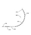
図6は、湾曲した構成の操縦可能ガイドワイヤの遠位端400を説明する。遠位端400は、遠位外管102、内管104、外管ルーメン214、ノーズコーン118、複数の外管縦方向切れ目または溝穴218、および複数の外管部分的横方向切れ目216を備える。
FIG. 6 illustrates the steerable guidewire
図6を参照すると、外管の部分的横方向切れ目216は、横方向切れ目216が位置する外管側部が圧縮されたときに塞がる間隔を表している。そのような圧縮は、外管102を内管104に対し相対的に遠位に押すことによって発生する。部分的横方向切れ目216の間隙が閉じると、さらに圧縮することは非常に難しくなるが、これは圧縮のための間隙がもう存在しないと外管102がかなり硬くなるからである。内管104が外管102内で同軸的に入れ子になっている複合構造は、どのような量の曲率が生じていても、比較的硬く、よじれに抵抗する。
Referring to FIG. 6, a partial lateral cut 216 in the outer tube represents the interval that is closed when the outer tube side where the lateral cut 216 is located is compressed. Such compression occurs by pushing the
好ましい遠位端の曲率半径は、約0.25インチから約6インチの範囲であり得、好ましい範囲は約0.5インチから約2インチであり、さらに好ましい範囲は約0.5インチから約1.5インチである。曲率半径は一定である必要はない。可撓性領域の近位端は可撓性領域の遠位端よりも部分的横方向切れ目216が広い間隔で配置され得るので、遠位端は可撓性領域の近位端よりも急な半径範囲に屈曲する。他の実施形態では、遠位領域は可撓性領域の近位端よりも可撓性が低い場合がある。
A preferred distal end radius of curvature may range from about 0.25 inches to about 6 inches, with a preferred range of about 0.5 inches to about 2 inches, and a more preferred range of about 0.5 inches to about 2 inches. 1.5 inches. The radius of curvature need not be constant. The proximal end of the flexible region may be more widely spaced with partial
外管102の部分的横方向切れ目216および「T字型」溝穴は、好ましくは、エッチング、電解研磨、パッシベーション、研摩、ばり取り、機械加工、または他のプロセスにより加工されて、部分的横方向切れ目216の外縁が丸くされる。
このように縁部は鈍いかまたは丸くされているので、操縦可能ガイドワイヤがカテーテル、ダイレータ、またはオブチュレータの内側の材料掘ったり、削ったり、剃り落してしまうように鋭利ではない。
The partial
Thus, the edges are blunt or rounded so that the steerable guidewire is not as sharp as digging, shaving or shaving material inside the catheter, dilator, or obturator.
図7Aは、外管700の遠位可撓性区分の領域の別の実施形態の上面図を説明し、外管700は、さらにダブテール702を備える複数の部分的横方向切れ目または溝穴706を備えている。
ダブテール702は溝702を形成し、外管700に中立的に力が加わっている限り、または部分的横方向切れ目または溝穴706の側部に圧縮されて力が加わっている限り、さらに溝702に載るかまたは溝702内で周方向に束縛されるペグまたは突起704を備える。ダブテール溝702内に載っている突起704は、ダブテール702の領域にトルク抵抗性およびねじれ剛性を提供する。
FIG. 7A illustrates a top view of another embodiment of the region of the distal flexible section of the
The
図12Bは、外管700の遠位可撓性区分の領域の側面図を説明し、外管700は、部分的横方向溝穴706、さらに突起704を備えるダブテール702、および「T字型」溝穴218を備えている。
T字型溝穴218は随意であるか、または異なる構成であり得る。
FIG. 12B illustrates a side view of the region of the distal flexible section of the
T-shaped
操縦可能ガイドワイヤは、心臓血管系、呼吸器系、消化器系、または最小限の侵襲アクセスが有益である管状腔を含む任意の他の系において使用することができる。本発明の操縦可能ガイドワイヤは、一体型で操縦可能である。操縦可能であってもなくてもよい他のカテーテルと一緒に使用されるように構成されるが、本発明に開示の操縦可能ガイドワイヤは、自体が操縦可能であるかまたは関節的動作をするので、操縦可能であるために外部の操縦可能カテーテルまたは操縦性を有するカテーテルを必要としない。
操縦可能ガイドワイヤは、事実上無限の回数屈曲し伸びることができる。操縦可能ガイドワイヤは、独自の操縦システムを備えるので、操縦可能でないカテーテルとの併用では特に有用である。
The steerable guidewire can be used in the cardiovascular system, respiratory system, digestive system, or any other system that includes a tubular cavity where minimal invasive access is beneficial. The steerable guidewire of the present invention is steerable in one piece. Although configured to be used with other catheters that may or may not be steerable, the steerable guidewire disclosed in the present invention is itself steerable or articulates Thus, no external steerable catheter or steerable catheter is required to be steerable.
The steerable guidewire can be bent and stretched virtually indefinitely. Steerable guidewires are particularly useful in conjunction with non-steerable catheters because they have their own steering system.
操縦可能ガイドワイヤは、役目を果たすとカテーテルのルーメンから回収されることができる。操縦可能ガイドワイヤを回収しなければ、外径は所定であるので、ルーメンの障害となりシースがカテーテルを導入する容量が減る。このデバイスはカテーテルとの併用を目的とするが、カテーテルと一体での使用は目的としない。操縦可能ガイドワイヤ・デバイスは、自体を操縦し、カテーテルを操縦することができるが、操縦可能カテーテルの代替ではない。 The steerable guidewire can be withdrawn from the lumen of the catheter when served. If the steerable guidewire is not retrieved, the outer diameter is predetermined, which can obstruct the lumen and reduce the capacity for the sheath to introduce the catheter. This device is intended for use with a catheter, but not for use with a catheter. A steerable guidewire device can steer itself and steer a catheter, but is not a substitute for a steerable catheter.
本明細書に開示の操縦機構は、他の種類のカテーテル、ガイドカテーテル、イントロデューサ、シース、ガイドワイヤ、パンチ、針、または前述のデバイス内に配置されているオブチュレータでさえも、250cm以上の長い長さにわたり高度の制御性で操縦するのに使用され得るが、必要とする壁厚はより薄いので、同じ外径を有する従来技術の操縦可能デバイスと比べて、より大きい内部ルーメンを可能にする。
典型的なシースは、たとえば3Frから12Frの容量の内部ルーメンを有し得、なおも1Fr前後の非常に薄い壁を維持している。約2Frから5Frの範囲のルーメンを有するより細いカテーテルまたはガイドカテーテルは、シースの壁を作るのに用いられる材料しだいだが、さらに薄い壁厚を有し得る。
一部のシース構造は、金属製の内管と、ポリマー外部コーティングを有する金属製外管などの複合材料を含み得る。内管はさらに、たとえばPTFEまたは他のフルオロポリマー(PFA、FEP)、パリレン、Pebax(登録商標)、Hytrel(登録商標)、ポリイミド、ポリアミド、PET等の内部ライナーで被覆されて、確実に低下した摩擦特性、電気絶縁特性、またはその両方を生成する。これらのコーティングまたはライナーの厚さは、約0.0001インチから約0.005インチの範囲であり得、好ましい厚さの範囲は約0.0005インチから約0.002インチである。
The steering mechanism disclosed herein can be other types of catheters, guide catheters, introducers, sheaths, guidewires, punches, needles, or even obturators placed in the aforementioned devices, longer than 250 cm. Can be used for maneuvering with a high degree of control over length, but requires less wall thickness, allowing a larger internal lumen compared to prior art steerable devices with the same outer diameter .
A typical sheath may have an internal lumen with a capacity of, for example, 3 Fr to 12 Fr and still maintain a very thin wall around 1 Fr. Thinner catheters or guide catheters having lumens in the range of about 2 Fr to 5 Fr can have even thinner wall thickness, depending on the material used to make the sheath wall.
Some sheath structures may include composite materials such as a metallic inner tube and a metallic outer tube with a polymer outer coating. The inner tube is further covered with an inner liner such as PTFE or other fluoropolymers (PFA, FEP), Parylene, Pebax®, Hytrel®, polyimide, polyamide, PET, etc. Produces friction properties, electrical insulation properties, or both. The thickness of these coatings or liners can range from about 0.0001 inches to about 0.005 inches, with a preferred thickness range being about 0.0005 inches to about 0.002 inches.
本明細書に開示の操縦機構は、2つ以上の入れ子式の軸方向に細長い、互いに対し相対的に縦軸線方向のみに移動する円筒状管を備え、極めて薄い壁および内径(ID)と外径(OD)の大きい比を有する構成で、高い精度、反復可能性、力、柱強度、ねじれ制御等を提供することができる。
管のうちの1本は、部分的横方向切れ目または複合的横方向間隙を備え、もう1本は実質的に可撓性領域の長さ方向に走る分割を備える。分割管の非接続側部は、除去して、部分的に形成された接続側部だけを残すことができる。しかし、好ましい実施形態では、非接続側部は実際には遠位端のところで保持されて、除去されず、外管102のルーメン内のスペースを埋めて、よじれを防止し、柱強度を高め、ルーメンの潰れを防止し、中心スタイレットまたはカテーテルに案内を提供する。
従来技術のデバイスは、より厚い壁厚を必要とし、その結果所与の外径に対する内部ルーメンのサイズが小さくなるか、または、デバイスの近位端からの制御下で、遠位先端が同程度の精度では動かない。
The steering mechanism disclosed herein comprises two or more nested axially elongated cylindrical tubes that move only in the longitudinal direction relative to each other, with very thin walls and an inner diameter (ID) and an outer A configuration having a large ratio of diameter (OD) can provide high accuracy, repeatability, force, column strength, torsion control, and the like.
One of the tubes comprises a partial transverse cut or multiple transverse gaps, and the other comprises a split running substantially along the length of the flexible region. The non-connecting side of the dividing tube can be removed, leaving only the partially formed connecting side. However, in a preferred embodiment, the unconnected side is actually held at the distal end and is not removed, filling the space in the lumen of the
Prior art devices require a thicker wall thickness resulting in a smaller internal lumen size for a given outer diameter or comparable distal tip under control from the proximal end of the device It does not move with the accuracy of.
図8は、ガイドカテーテル814のダイレータ、またはオブチュレータ810の中心ルーメン812を通って進められた操縦可能ガイドワイヤの遠位端400の側面図を説明する。
操縦可能ガイドワイヤの遠位端400は、複数の部分的横方向切れ目216を備える外管102、および遠位端220を備える内管104を備える。遠位端220は、丸く鈍い非外傷性遠位端806を備えるか、またはそれで終わっている。操縦可能ガイドワイヤの遠位端400はさらに中心ルーメン(図示せず)を備え得る。ガイドカテーテル814はさらに中心ルーメン816を備える。
FIG. 8 illustrates a side view of the steerable guidewire
The steerable guidewire
外管102は改変されて剛性を調節することができる。屈曲に対する抵抗を増大させ、外管102の近位よりも遠位を動かすことが優先される場合がある。この屈曲抵抗の増大は、外管が遠位領域よりも可撓性領域の近位端において、より激しく屈曲する傾向と矛盾する。屈曲半径がほぼ一定となるように、または屈曲可能領域の遠位端に向けて移動してより大きい曲げ(より小さい屈曲半径)が生じるように、屈曲を構成することが可能である。
部分的横方向溝穴216は、深さを減じてより近位で切って、外管102により与えられる屈曲に対する抵抗を増大させることができる。部分的横方向溝穴216は、より近位の領域でより狭く切って、溝穴216が閉じることができる距離を減じることができる。
T字型溝穴218は、長さを短くするか、または外管102の可撓性領域のより近位の領域に移動させることができる。エラストマーバンパーまたはフィラーをいくつかの部分的横方向溝穴216に加えて、部分的横方向溝穴216が圧縮できる量を減じることができる。
部分的横方向溝穴216がT字型溝穴218と連動して外管102の屈曲下で閉じてしまうと、さらなる屈曲は阻止されて実質的に抑止される。部分的横方向溝穴216の幅と間隔を調整することによって、所与のカテーテルの特定の最終曲率が調整され得る。
The
The partial
The T-shaped
If the partial
図9Aは、ルーメン214、近位管壁212、複数の部分的横方向溝穴216、複数のT字型溝穴218、短い部分的横方向溝穴902、わずかにより長い部分的横方向溝穴904、および短くされたT字型溝穴906を有するが標準長の横方向溝穴216を備える外管210を説明する。
9A shows
図9Aを参照すると、最近位の部分的横方向溝穴902は、標準の部分的横方向溝穴216よりも浅く切り込んでいる。(遠位に移動して)第2の部分的横方向溝穴904は、溝穴902よりもわずかに長いので、その領域においてより可撓性があり、屈曲を生じるのにより少ない力を要する。第3の部分的横方向溝穴は、管が一定の屈曲力を与えられて屈曲する能力を減じる、短くされたT字型溝穴906を備える。
Referring to FIG. 9A, the proximal partial
図9Bは、ルーメン224、近位領域222、接続側部232、遠位端230、丸い先端118、および遠位端230の近位端のべベル状導入部910を備える内管220を説明する。
FIG. 9B illustrates an
図9Bを参照すると、非接続領域の近位端は遠位に動かされて、内管220の特定の領域、一般にはこの遠位可撓性領域の最近位部の剛性を増大させることができる。
Referring to FIG. 9B, the proximal end of the disconnected region can be moved distally to increase the stiffness of a particular region of the
特定の好ましい実施形態では、内管220が圧縮を維持して、外管210の遠位端において湾曲された後直線状に戻る屈曲を生じさせ、直線を越えてさらに向こう(反対)の方向に屈曲させることができることが有益である。圧縮を維持するために、管のほぼ中心または真ん中またはその近くで、非接続側部234が接続側部232から分離されていることが有益である。非接続側部234を接続側部232から分離する溝穴226の幅によっては、溝穴の位置は真ん中からずれ得るが、これは内管220の壁厚と、溝穴切りの角度に左右される。好ましい実施形態では、非接続側部234と接続側部232間には干渉が存在するので、非接続側部と力伝達部材とは実質的に内向きに移動することができず、この内向きの移動は、ルーメンをふさぎ、ルーメンを通る流体の流れを制限し、ルーメン内を縦方向に移動する必要のあるスタイレットまたは他のカテーテルを捕捉し、または接続側部232に縦方向の圧縮力が加わるのを防止するのに十分な座屈といった負の効果を有する状況である。
In certain preferred embodiments, the
図10Aは、操縦可能ガイドワイヤの可撓性領域において、外管710の中に入れ子になり、半径方向の間隙1002によって外管710から分離されている内管720の横断面図を説明し、内管720は、分裂または間隙726によって、断面のだいたい(または実質的に)正中線または中心線で、2つのだいたいまたは実質的に等価な要素である接続側部732と非接続側部734とに分離されている。
Figure 10A, in the flexible region of the steerable guide wire, becomes nested within the
図10Bは、操縦可能ガイドワイヤの可撓性領域において、外管710の中に入れ子になり、半径方向の間隙1002によって外管710から分離されている内管720の横断面図を説明し、内管720は、分裂または間隙726によって、断面の正中線または中心線から実質的に外れて、2つの実質的に不等価な要素である接続側部732と非接続側部734とに分離されている。
Figure 10B, in the flexible region of the steerable guide wire, becomes nested within the
図10Aおよび図10Bを参照すると、非接続側部734は、その剛性と変形不能性によって外管710に最接近して保持されているので、非接続側部734の縁部は接続側部732の縁部を通り越すことができ、したがって2つの側部732と側部734とは中心線から半径方向に変位して保持される。間隙726が大きすぎるか、側部732および734のいずれかが他方の縁部内に嵌るほど小さいとすると、一側部の中央線に向けての変位、および接続側部732または734の中心を外れる向きの交絡(confounding)が生じることにもなり、その結果接続側部732が圧縮されて座屈したり、屈曲した操縦可能ガイドワイヤをまっすぐにすることができなくなったりする。別の問題としては、トルク伝達性および屈曲の方向の予測可能性が失われることになり得る。図10Aと図10Bに示す実施形態はどちらも、内管の接続側部732の非接続側部734に対する相対的な周方向および半径方向の向きを維持しており、遠位先端の高精度の偏向を促進している。
Referring to FIGS. 10A and 10B, the
好ましい実施形態では、半径方向の間隙1002は最小限にされ、操縦可能ガイドワイヤの外径が約0.035インチのとき、約0.0005インチから0.002インチの間に保持される。さらに、分裂または間隙226はできるだけ最小であるべきであり、好ましい実施形態では約0.0005インチから0.003インチの範囲であり得、約0.0005インチから0.02インチの間隙が最も好ましい。
In a preferred embodiment, the
図11は、操縦可能ガイドワイヤ1100の遠位端ならびに中間領域の一部分の一部破断側面図を説明する。
操縦可能ガイドワイヤ1100は、内管104、コイル巻き中間外管108、遠位外側コイル1102、ノーズコーン118、バックボーン1104、外側ポリマーコーティング106、および遠位コイル間隔1110を備える。
FIG. 11 illustrates a partially broken side view of the distal end of the
The
外側ポリマーコーティング106は操縦可能ガイドワイヤ1100(または100)の全長を延びることができ、または、長さの一部分だけを延びることができ、近位区分、1つまたは複数の中間区分108、遠位領域1102、またはそれらの組合せなど特定の区分に対応することができる。
外側ポリマー領域は、限定ではないが、Hytrel、Pebax、ポリウレタン、シリコーンゴム等などのエラストマーを含むことができ、シリコーン油、シリコーングリースまたはゲル、フルオロポリマー、ポリイミド等などの追加の減摩コーティングで被覆され得る。
The
The outer polymer region can include elastomers such as, but not limited to, Hytrel, Pebax, polyurethane, silicone rubber, etc., and coated with an additional anti-friction coating such as silicone oil, silicone grease or gel, fluoropolymer, polyimide, etc. Can be done.
遠位コイル1102はその近位端を中間コイル108の遠位端に取り付けられ、その遠位端をノーズコーン118に取り付けられる。内管104は、ノーズコーン118近傍の領域で遠位コイル1102に取り付けられるので、遠位コイルの大部分またはほぼ全部の伸張と収縮が内管104によって制御される。
遠位コイル1102は間隔1110を備え、該間隔の大きさは0.0005インチから約0.020インチ以上の範囲であり得る。図示の実施形態では、コイルの間隔1110は幅がコイル要素の直径にだいたい等しい。コイル要素の直径は、約0.0005インチから約0.010インチの範囲であり得、優先的には直径が約0.001インチから約0.007インチの範囲である。コイルの材料は、限定ではないが、ニチノール、ポリイミド、ステンレス鋼、チタン、コバルト・ニッケル合金等などの材料を含み得る。コイルの材料は、好ましくは、展性が低く、ばね硬さが高い材料特性を備えている。
The
図11および図2を参照すると、バックボーン1104が、内管104がより近位の構造体から切り離されている操縦可能ガイドワイヤ1100の側部234に位置している。したがって、接続側部232を通って伝達される軸方向に向けられる力は、接続側部232のほうが非接続側部234よりも自由でありバックボーン1104によってかけられる制限もより低い状態で、ばねコイル1102を縦方向に圧縮または伸長させる。この結果、非対称な力が遠位端にかかり、遠位端は操縦可能ガイドワイヤ1100の近位端からの制御下で縦軸線から離れて偏向することになる。
Referring to FIGS. 11 and 2, the
図12は、さらに縦方向溝穴226を備える内管104、中間外管108、ポリマーコーティング106、ノーズコーン118、さらに複数の横方向溝穴1210およびバックボーン1208を備える遠位外管1202を備える操縦可能ガイドワイヤ1200の遠位端を説明する。
FIG. 12 further illustrates steering with an
図12を参照すると、遠位外管1202は、EDM、ワイヤEDM、レーザー加工、光化学エッチング、一般的機械加工等によって与えられる溝穴1210または間隙を備える管として製造され得る。
遠位外管1202の近位端は、中間外管108の遠位端に取り付けられている。遠位外管1202の遠位端は、先端部またはノーズコーン118に取り付けられている。外管1202の遠位端はまた、縦方向溝穴226の遠位端よりも実質的に遠位で内管104に取り付けられて、その点での回転および横方向の相対移動を防止している。
バックボーン1208は、間隙1210を非対称に伸びさせ縮ませて、遠位外管1202の縦軸線から横方向の屈曲または湾曲を生じさせる。
Referring to FIG. 12, the distal
The proximal end of the distal
The
本明細書に記載の実施形態は、プルワイヤを使用しないシステムを説明している。
外管にも内管にもサイドルーメンは必要ない。特定の従来技術のカテーテルに見られるようなそのようなサイドルーメンは、サイドルーメンを取り囲むのに広い断面積を要し、カテーテルの外周りは限られているので、中心ルーメンに使用可能な面積から削除してしまう。プルワイヤの使用は、特定の従来技術のカテーテルのものなどを必要とし、これらの構造体を外管の一側部に保持することは、困難かまたは不可能であり得る。
サイドルーメンまたはチャネルは、プルワイヤまたは制御ロッドを正しい位置に保持して、正しい偏心力を提供して遠位端を屈曲させるのに必要とされる。サイドルーメンはまた、制御ロッドまたはプルワイヤを、中を開けてほぼ円形に維持される必要がある中心ルーメンから出しておくのに必要とされる。本明細書に開示のシステムはしかし、高度な柱強度、最高のトルク伝達性、最大限の中心ルーメン、および非常に強度な制御および操縦機能または能力を保持する。
さらに、サイドルーメンまたはチャネルは、デバイスの関節的動作をする遠位端のために空間性(回転方向)を維持するのに必要である。軸方向の摺動性を許可するが半径方向の抑制を生成するサイドルーメンまたはチャネルがなければ、プルワイヤまたはプッシュロッドはデバイスの中心ルーメン内で自由に動き回ることにもなり、デバイスを望ましくない方向に屈曲させることもあり得る。比較的小さい断面積をもつ長いガイドワイヤは、ねじれや回転的ずれを非常に生じやすいので、何らかの方法をとって、関節的動作をする装置の正しい周方向位置を維持しなければならない。
The embodiments described herein describe a system that does not use a pull wire.
Side lumens are not required for either the outer or inner tube. Such side lumens, such as found in certain prior art catheters, require a large cross-sectional area to surround the side lumens, and the outer circumference of the catheter is limited, thus reducing the area available for the central lumen. It will be deleted. The use of pull wires requires such as that of certain prior art catheters, and it may be difficult or impossible to hold these structures on one side of the outer tube.
Side lumens or channels are required to hold the pull wire or control rod in place to provide the correct eccentric force and bend the distal end. Side lumens are also required to keep the control rod or pull wire out of the central lumen that needs to be opened and maintained in a generally circular shape. The system disclosed herein, however, retains high column strength, maximum torque transmission, maximum center lumens, and very strong control and steering functions or capabilities.
Furthermore, side lumens or channels are necessary to maintain spatiality (direction of rotation) for the articulating distal end of the device. Without side lumens or channels that allow axial slidability but create radial restraints, the pull wire or push rod can also move freely within the central lumen of the device, causing the device to move in an undesired direction. It can be bent. Long guidewires with a relatively small cross-sectional area are very prone to torsion and rotational misalignment, and some method must be taken to maintain the correct circumferential position of the articulating device.
さらに、従来技術のデバイスで使用されるようなプルワイヤは、デバイスの遠位端に対し圧縮を生じることができないので、プルワイヤはデバイスの遠位端を圧縮下で動かしたり関節的動作させたりできなかった。プルワイヤは、張力がかかって遠位端を動かしたり関節的動作させたりできるので、遠位端を逆方向に動かすのに、対抗するプルワイヤ、形状記憶金属、またはばねの戻りの付勢などなんらかの種類の逆の力を必要とすることになる。 In addition, pull wires such as those used in prior art devices cannot cause compression against the distal end of the device, so the pull wire cannot move or articulate the distal end of the device under compression. It was. The pull wire can be tensioned to move or articulate the distal end, so any kind of counter pull wire, shape memory metal, or spring return bias to move the distal end in the opposite direction The opposite force of will be required.
しかし、管状または円筒状の(実質的にルーメンのない)中央制御デバイスは、圧縮されてもその構造を維持し、外側の円筒状の軸方向に細長い管内で周方向位置を維持し、精密制御を維持し、十分な引っ張り強さを維持して力を及ぼし、かつ他のどの種類の操縦可能デバイスよりも大きい中心ルーメンを維持することができる。内管に縦方向の溝穴が設けられていても座屈に対する抵抗が生じるのは、内管は非常にきつい公差で外管内に束縛されているので、圧縮されてもそのまっすぐな向きから外れて屈曲できないからである。 However, a tubular or cylindrical (substantially lumen-free) central control device maintains its structure when compressed, maintains a circumferential position within the outer cylindrical axially elongated tube, and provides precise control And maintain sufficient tensile strength to exert a force and maintain a central lumen that is larger than any other type of steerable device. Even if the inner tube is provided with a longitudinal slot, resistance to buckling occurs because the inner tube is constrained within the outer tube with very tight tolerances, so that even if compressed, it will deviate from its straight orientation. Because it cannot be bent.
デバイスおよび方法を開発した環境に関連して好ましい実施形態を記載してきたが、それらは本発明の原理を単に説明するものである。さまざまな実施形態の要素を他の各種に組み入れて、それらの要素の利点をそのような他の種と組み合わせて得ることができ、さまざまな有用な特徴を単独または互いに組み合わせて実施形態に用いることができる。他の実施形態および構成を、本発明の精神および添付の請求項の範囲から逸脱することなく、考案することができる。 Although preferred embodiments have been described in connection with the environment in which the device and method were developed, they merely illustrate the principles of the invention. The elements of the various embodiments can be incorporated into various other types and the benefits of those elements can be obtained in combination with such other species, and various useful features can be used in the embodiments alone or in combination with each other. Can do. Other embodiments and configurations may be devised without departing from the spirit of the invention and the scope of the appended claims.
Claims (10)
近位端、遠位端、および前記遠位端における可撓性領域を特徴とする外管であって、前記可撓性領域もまた近位端および遠位端を特徴とする、外管と、
近位端および遠位端を特徴とする内管またはロッドであって、前記内管またはロッドの前記遠位端近くに可撓性領域を有する、内管またはロッドと、
前記外管内の、前記外管の長さを実質的に延びるルーメンとを備え、
前記外管または前記内管もしくはロッドのうちの1つが非外傷性遠位先端を有し、
前記内管またはロッドは前記外管の前記ルーメン内に配置され、前記外管の前記近位端から前記外管の前記遠位端に延び、前記外管の前記遠位端のところで遠位に終わり、前記内管またはロッドは、前記外管の前記可撓性領域の前記遠位端に近接する前記外管の箇所で、前記外管に縦方向に固定されており、
前記内管またはロッドの前記可撓性領域は、前記内管またはロッドに配置された長手方向に向けられたスリットを備えている、操縦可能ガイドワイヤ。 A steerable guidewire,
An outer tube characterized by a proximal end, a distal end, and a flexible region at the distal end, wherein the flexible region is also characterized by a proximal end and a distal end; ,
An inner tube or rod characterized by a proximal end and a distal end, the inner tube or rod having a flexible region near the distal end of the inner tube or rod;
A lumen in the outer tube that extends substantially the length of the outer tube;
One of the outer tube or the inner tube or rod has an atraumatic distal tip;
The inner tube or rod is disposed within the lumen of the outer tube and extends from the proximal end of the outer tube to the distal end of the outer tube and distally at the distal end of the outer tube. End, the inner tube or rod is longitudinally secured to the outer tube at the location of the outer tube proximate to the distal end of the flexible region of the outer tube;
The steerable guidewire, wherein the flexible region of the inner tube or rod comprises a longitudinally oriented slit disposed on the inner tube or rod.
前記内管またはロッドの前記可撓性領域は、縦方向に向けられた溝穴を有する前記内管またはロッドの区分を備えている、請求項1に記載の操縦可能ガイドワイヤ。 The flexible region of the outer tube comprises a section of the outer tube that is snake cut with a plurality of radially oriented slots formed in a wall of the outer tube, The directed slots are aligned substantially radially along one side of the outer tube;
The steerable guidewire of claim 1, wherein the flexible region of the inner tube or rod comprises a section of the inner tube or rod having a longitudinally oriented slot.
前記軸方向に細長い外管の前記近位端に取り付けられているねじジャッキトラベラー要素であって、前記ねじジャッキトラベラー要素はその外表面の少なくとも一部分にトラベラーねじを備え、さらに、前記ねじジャッキトラベラー要素の移動に応答して、前記外管は前記ハブおよび前記内管またはロッドに対し相対的に軸方向に移動することができる、ねじジャッキトラベラー要素と、
前記ハブに取り付けられ、ユーザーによって回転させられることができるつまみであって、内部ルーメンにつまみねじを備えて、前記つまみねじと前記トラベラーねじが係合する、つまみと、
前記つまみが回転させられたとき、前記つまみが前記ハブに対し相対的に縦方向に動くのを防止するように構成されている、固定要素と
をさらに備えている、請求項1に記載の操縦可能ガイドワイヤ。 A hub attached to the proximal end of the inner tube or rod, the hub receiving a screw jack traveler element and preventing the screw jack traveler element from rotating about the longitudinal axis of the hub. A hub comprising an inner lumen that is constrained so that the inner tube or rod does not move relative to the hub;
A screw jack traveler element attached to the proximal end of the axially elongated outer tube, the screw jack traveler element comprising a traveler screw on at least a portion of its outer surface, and further comprising the screw jack traveler element A screw jack traveler element capable of axially moving relative to the hub and the inner tube or rod in response to movement of the outer tube;
A knob attached to the hub and capable of being rotated by a user, comprising a thumbscrew in an internal lumen, the knob screw and the traveler screw engaging;
The steering of claim 1, further comprising: a stationary element configured to prevent the knob from moving longitudinally relative to the hub when the knob is rotated. Possible guide wire.
Applications Claiming Priority (5)
| Application Number | Priority Date | Filing Date | Title |
|---|---|---|---|
| US201261734297P | 2012-12-06 | 2012-12-06 | |
| US61/734,297 | 2012-12-06 | ||
| US13/750,689 | 2013-01-25 | ||
| US13/750,689 US8961550B2 (en) | 2012-04-17 | 2013-01-25 | Steerable endoluminal punch |
| PCT/US2013/073262 WO2014089273A1 (en) | 2012-12-06 | 2013-12-05 | Steerable guidewire and method of use |
Publications (3)
| Publication Number | Publication Date |
|---|---|
| JP2015536226A JP2015536226A (en) | 2015-12-21 |
| JP2015536226A5 JP2015536226A5 (en) | 2016-07-28 |
| JP6412505B2 true JP6412505B2 (en) | 2018-10-24 |
Family
ID=50883982
Family Applications (1)
| Application Number | Title | Priority Date | Filing Date |
|---|---|---|---|
| JP2015545833A Active JP6412505B2 (en) | 2012-12-06 | 2013-12-05 | Steerable guidewire and method of use |
Country Status (5)
| Country | Link |
|---|---|
| US (2) | US11317938B2 (en) |
| EP (1) | EP2928539B1 (en) |
| JP (1) | JP6412505B2 (en) |
| CN (1) | CN104968390B (en) |
| WO (1) | WO2014089273A1 (en) |
Families Citing this family (21)
| Publication number | Priority date | Publication date | Assignee | Title |
|---|---|---|---|---|
| US9993266B2 (en) | 2014-09-13 | 2018-06-12 | Indian Wells Medical, Inc. | Steerable endoluminal punch |
| JP6902533B2 (en) | 2015-10-02 | 2021-07-14 | コーニンクレッカ フィリップス エヌ ヴェKoninklijke Philips N.V. | Hub for device placement with shape detection system |
| WO2017147041A1 (en) | 2016-02-22 | 2017-08-31 | Arizona Board Of Regents On Behalf Of Arizona State University | Adjustable guidewire |
| US10786655B2 (en) | 2016-03-14 | 2020-09-29 | Indian Wells Medical, Inc. | Steerable guidewire and method of use |
| CN105816208B (en) * | 2016-05-25 | 2018-08-21 | 南京微创医学科技股份有限公司 | A kind of seal wire lock on endoscope |
| US10821268B2 (en) * | 2016-09-14 | 2020-11-03 | Scientia Vascular, Llc | Integrated coil vascular devices |
| CN106823099A (en) * | 2016-12-28 | 2017-06-13 | 苏州科技城医院 | Cvc |
| AU2018237357B2 (en) | 2017-03-22 | 2023-11-23 | University Of Maryland Medical System Corporation | Device and method for transseptal puncture |
| CN106937897A (en) * | 2017-04-26 | 2017-07-11 | 上海百心安生物技术有限公司 | The Transmission system and preparation method of a kind of bioabsorbable stent |
| WO2019027768A1 (en) | 2017-08-02 | 2019-02-07 | Malekmehr Farshad | Guidewire |
| US11045224B2 (en) | 2018-09-24 | 2021-06-29 | University Of Maryland, Baltimore | Apparatus and method for septal punch |
| EP3510914A1 (en) * | 2018-01-15 | 2019-07-17 | Koninklijke Philips N.V. | Device with bendable distal portion and system actuating the distal portion of the device |
| WO2020019307A1 (en) * | 2018-07-27 | 2020-01-30 | 尚华 | Memory metal optical fiber puncture needle tube |
| WO2020019306A1 (en) * | 2018-07-27 | 2020-01-30 | 尚华 | Optical fiber puncture needle tube and application thereof |
| CA3112905C (en) * | 2018-09-24 | 2023-08-22 | EndoWays LTD. | Catheterization apparatus, catheter, and method |
| CN109363809B (en) * | 2018-11-21 | 2021-12-03 | 辽宁垠艺生物科技股份有限公司 | Adjusting device of filament control type medical instrument |
| US10918366B2 (en) | 2018-12-28 | 2021-02-16 | DePuy Synthes Products, Inc. | Steerable locking catheter |
| CN114683222A (en) * | 2020-12-31 | 2022-07-01 | 北京晓聪科技有限公司 | Device with handle |
| US11648025B1 (en) | 2021-07-30 | 2023-05-16 | Indian Wells Medical, Inc. | Steerable endoluminal punch with introducer and guidewire |
| CN115106600A (en) * | 2021-10-25 | 2022-09-27 | 美度可医疗科技(上海)有限公司 | Composite guide wire with high coaxiality and uneasy kinking and welding method thereof |
| CN114404780A (en) * | 2022-01-24 | 2022-04-29 | 成都维宁生物技术有限公司 | Non-sac leak-proof indwelling catheter and manufacturing method and application thereof |
Family Cites Families (39)
| Publication number | Priority date | Publication date | Assignee | Title |
|---|---|---|---|---|
| US3802440A (en) * | 1972-12-19 | 1974-04-09 | M Salem | Intubation guide |
| US4757827A (en) * | 1987-02-17 | 1988-07-19 | Versaflex Delivery Systems Inc. | Steerable guidewire with deflectable tip |
| US4815478A (en) | 1987-02-17 | 1989-03-28 | Medtronic Versaflex, Inc. | Steerable guidewire with deflectable tip |
| US5470308A (en) | 1992-08-12 | 1995-11-28 | Vidamed, Inc. | Medical probe with biopsy stylet |
| US5564440A (en) | 1993-11-03 | 1996-10-15 | Daig Corporation | Method for mopping and/or ablation of anomalous conduction pathways |
| US5989281A (en) | 1995-11-07 | 1999-11-23 | Embol-X, Inc. | Cannula with associated filter and methods of use during cardiac surgery |
| US6217527B1 (en) * | 1998-09-30 | 2001-04-17 | Lumend, Inc. | Methods and apparatus for crossing vascular occlusions |
| US20060074442A1 (en) * | 2000-04-06 | 2006-04-06 | Revascular Therapeutics, Inc. | Guidewire for crossing occlusions or stenoses |
| US6221047B1 (en) | 1998-07-31 | 2001-04-24 | Albany Medical College | Safety intravenous catheter assembly and method for use with a needle |
| US6146338A (en) * | 1999-04-23 | 2000-11-14 | Medtronic, Inc. | Apparatus for deflecting a catheter or lead |
| US6650923B1 (en) | 2000-04-13 | 2003-11-18 | Ev3 Sunnyvale, Inc. | Method for accessing the left atrium of the heart by locating the fossa ovalis |
| US6607496B1 (en) * | 2000-09-12 | 2003-08-19 | Medtronic, Inc. | Steerable stylet with enhanced torsional transfer strength |
| US6419641B1 (en) * | 2000-11-28 | 2002-07-16 | Promex, Llc | Flexible tip medical instrument |
| US20050267495A1 (en) | 2004-05-17 | 2005-12-01 | Gateway Medical, Inc. | Systems and methods for closing internal tissue defects |
| JP2003273939A (en) | 2002-03-13 | 2003-09-26 | Nec Corp | Multiplex transmission system, converter and alarm transfer method |
| US20050004515A1 (en) | 2002-11-15 | 2005-01-06 | Hart Charles C. | Steerable kink resistant sheath |
| US20040193073A1 (en) * | 2003-03-31 | 2004-09-30 | Demello Richard M. | Composite guidewire with a linear elastic distal portion |
| US7309355B2 (en) * | 2003-06-27 | 2007-12-18 | Depuy Mitek, Inc. | Flexible tibial sheath |
| JP4496223B2 (en) | 2003-11-06 | 2010-07-07 | エヌエムティー メディカル, インコーポレイティッド | Septal penetration device |
| US7632277B2 (en) | 2004-03-29 | 2009-12-15 | Woll Bioorthopedics Llc | Orthopedic intramedullary fixation system |
| US7678081B2 (en) * | 2004-07-12 | 2010-03-16 | Pacesetter, Inc. | Methods and devices for transseptal access |
| US8834562B2 (en) | 2005-07-07 | 2014-09-16 | Cordis Corporation | Patent foramen ovale closure device with steerable delivery system |
| US20070021767A1 (en) | 2005-07-25 | 2007-01-25 | Breznock Eugene M | Steerable endoluminal punch |
| US20070060878A1 (en) * | 2005-09-01 | 2007-03-15 | Possis Medical, Inc. | Occlusive guidewire system having an ergonomic handheld control mechanism and torqueable kink-resistant guidewire |
| US7972359B2 (en) | 2005-09-16 | 2011-07-05 | Atritech, Inc. | Intracardiac cage and method of delivering same |
| US8518052B2 (en) * | 2006-01-06 | 2013-08-27 | Cordis Corporation | Medical delivery system for delivery of a medically useful payload |
| US8414568B2 (en) * | 2006-04-04 | 2013-04-09 | The Spectranetics Corporation | Laser-assisted guidewire having a variable stiffness shaft |
| US7615044B2 (en) | 2006-05-03 | 2009-11-10 | Greatbatch Ltd. | Deflectable sheath handle assembly and method therefor |
| US20080045908A1 (en) * | 2006-08-16 | 2008-02-21 | Boston Scientific Scimed, Inc. | Medical device including a metallic tube fillet welded to a core member |
| US20080045863A1 (en) * | 2006-08-17 | 2008-02-21 | Ethicon Endo-Surgery, Inc. | Guidewire structure including a medical guidewire |
| DE602006019990D1 (en) * | 2006-12-07 | 2011-03-17 | Cordis Corp | Controllable catheter system |
| WO2008121888A1 (en) | 2007-03-30 | 2008-10-09 | Onset Medical Corporation | Expandable trans-septal sheath |
| US8540674B2 (en) | 2007-04-27 | 2013-09-24 | Cvdevices, Llc | Devices, systems, and methods for transeptal atrial puncture using an engagement catheter platform |
| US20090036832A1 (en) * | 2007-08-03 | 2009-02-05 | Boston Scientific Scimed, Inc. | Guidewires and methods for manufacturing guidewires |
| JP5331826B2 (en) | 2008-03-10 | 2013-10-30 | フォルティメディクス・サージカル・ベスローテン・フェンノートシャップ | Method of making an instrument for endoscopic use and instrument for endoscopic use obtained using this method |
| US20100185053A1 (en) | 2009-01-21 | 2010-07-22 | Monika Elizabeth Hagen | Transverse surgical tunneling |
| CN104548316B (en) | 2009-06-24 | 2018-01-26 | 施菲姆德控股有限责任公司 | Can steerable medical delivery devices and application method |
| JP2011212316A (en) | 2010-03-31 | 2011-10-27 | Fujifilm Corp | Bending-insertion assisting instrument and insertion path securing apparatus |
| US20110319905A1 (en) * | 2010-06-23 | 2011-12-29 | Palme Robert A | Multiple function vascular device |
-
2013
- 2013-12-05 CN CN201380072336.2A patent/CN104968390B/en active Active
- 2013-12-05 WO PCT/US2013/073262 patent/WO2014089273A1/en active Application Filing
- 2013-12-05 EP EP13861154.6A patent/EP2928539B1/en active Active
- 2013-12-05 JP JP2015545833A patent/JP6412505B2/en active Active
-
2018
- 2018-07-09 US US16/030,645 patent/US11317938B2/en active Active
-
2022
- 2022-05-02 US US17/734,748 patent/US20220265301A1/en active Pending
Also Published As
| Publication number | Publication date |
|---|---|
| JP2015536226A (en) | 2015-12-21 |
| EP2928539B1 (en) | 2019-11-27 |
| EP2928539A4 (en) | 2016-07-27 |
| CN104968390A (en) | 2015-10-07 |
| EP2928539A1 (en) | 2015-10-14 |
| CN104968390B (en) | 2019-04-23 |
| US11317938B2 (en) | 2022-05-03 |
| US20180317949A1 (en) | 2018-11-08 |
| WO2014089273A1 (en) | 2014-06-12 |
| US20220265301A1 (en) | 2022-08-25 |
Similar Documents
| Publication | Publication Date | Title |
|---|---|---|
| JP6412505B2 (en) | Steerable guidewire and method of use | |
| US10016210B2 (en) | Steerable guidewire and method of use | |
| US11844548B1 (en) | Steerable endoluminal punch | |
| US11819642B2 (en) | Steerable guidewire and method of use | |
| US10729457B2 (en) | Steerable endoluminal punch with cutting stylet | |
| US10485579B2 (en) | Steerable endoluminal punch | |
| CN109789292B (en) | Modular vascular catheter | |
| US8831707B2 (en) | Tip deflecting puncture needle | |
| EP3332830B1 (en) | Guide extension catheter | |
| JP7188847B2 (en) | Maneuverable devices and systems | |
| US11839401B2 (en) | Steerable endoluminal punch with cutting stylet | |
| EP3278832A2 (en) | Introducer with steerable distal tip section | |
| EP2687255B1 (en) | Guidewire with highly flexible tip | |
| US11786265B1 (en) | Steerable microcatheter and method of use | |
| US20240130753A1 (en) | Steerable Microcatheter and Method of Use | |
| US20230149671A1 (en) | Steerable Guidewire and Method of Use |
Legal Events
| Date | Code | Title | Description |
|---|---|---|---|
| A521 | Request for written amendment filed |
Free format text: JAPANESE INTERMEDIATE CODE: A523 Effective date: 20160609 |
|
| A621 | Written request for application examination |
Free format text: JAPANESE INTERMEDIATE CODE: A621 Effective date: 20161202 |
|
| A977 | Report on retrieval |
Free format text: JAPANESE INTERMEDIATE CODE: A971007 Effective date: 20170926 |
|
| A131 | Notification of reasons for refusal |
Free format text: JAPANESE INTERMEDIATE CODE: A131 Effective date: 20171024 |
|
| A521 | Request for written amendment filed |
Free format text: JAPANESE INTERMEDIATE CODE: A523 Effective date: 20180123 |
|
| A131 | Notification of reasons for refusal |
Free format text: JAPANESE INTERMEDIATE CODE: A131 Effective date: 20180703 |
|
| A521 | Request for written amendment filed |
Free format text: JAPANESE INTERMEDIATE CODE: A523 Effective date: 20180801 |
|
| TRDD | Decision of grant or rejection written | ||
| A01 | Written decision to grant a patent or to grant a registration (utility model) |
Free format text: JAPANESE INTERMEDIATE CODE: A01 Effective date: 20180904 |
|
| A61 | First payment of annual fees (during grant procedure) |
Free format text: JAPANESE INTERMEDIATE CODE: A61 Effective date: 20180928 |
|
| R150 | Certificate of patent or registration of utility model |
Ref document number: 6412505 Country of ref document: JP Free format text: JAPANESE INTERMEDIATE CODE: R150 |
|
| R250 | Receipt of annual fees |
Free format text: JAPANESE INTERMEDIATE CODE: R250 |
|
| R250 | Receipt of annual fees |
Free format text: JAPANESE INTERMEDIATE CODE: R250 |
|
| R250 | Receipt of annual fees |
Free format text: JAPANESE INTERMEDIATE CODE: R250 |