JP6407442B2 - Fixation, alignment and / or impulsiveness measuring method and apparatus for identifying and / or tracking brain function - Google Patents
Fixation, alignment and / or impulsiveness measuring method and apparatus for identifying and / or tracking brain function Download PDFInfo
- Publication number
- JP6407442B2 JP6407442B2 JP2017534772A JP2017534772A JP6407442B2 JP 6407442 B2 JP6407442 B2 JP 6407442B2 JP 2017534772 A JP2017534772 A JP 2017534772A JP 2017534772 A JP2017534772 A JP 2017534772A JP 6407442 B2 JP6407442 B2 JP 6407442B2
- Authority
- JP
- Japan
- Prior art keywords
- fixation
- housing
- mirror
- light
- subject
- Prior art date
- Legal status (The legal status is an assumption and is not a legal conclusion. Google has not performed a legal analysis and makes no representation as to the accuracy of the status listed.)
- Active
Links
Images


Classifications
-
- A—HUMAN NECESSITIES
- A61—MEDICAL OR VETERINARY SCIENCE; HYGIENE
- A61B—DIAGNOSIS; SURGERY; IDENTIFICATION
- A61B3/00—Apparatus for testing the eyes; Instruments for examining the eyes
- A61B3/10—Objective types, i.e. instruments for examining the eyes independent of the patients' perceptions or reactions
- A61B3/113—Objective types, i.e. instruments for examining the eyes independent of the patients' perceptions or reactions for determining or recording eye movement
-
- A—HUMAN NECESSITIES
- A61—MEDICAL OR VETERINARY SCIENCE; HYGIENE
- A61B—DIAGNOSIS; SURGERY; IDENTIFICATION
- A61B3/00—Apparatus for testing the eyes; Instruments for examining the eyes
- A61B3/10—Objective types, i.e. instruments for examining the eyes independent of the patients' perceptions or reactions
- A61B3/11—Objective types, i.e. instruments for examining the eyes independent of the patients' perceptions or reactions for measuring interpupillary distance or diameter of pupils
- A61B3/111—Objective types, i.e. instruments for examining the eyes independent of the patients' perceptions or reactions for measuring interpupillary distance or diameter of pupils for measuring interpupillary distance
-
- A—HUMAN NECESSITIES
- A61—MEDICAL OR VETERINARY SCIENCE; HYGIENE
- A61B—DIAGNOSIS; SURGERY; IDENTIFICATION
- A61B5/00—Measuring for diagnostic purposes; Identification of persons
- A61B5/0059—Measuring for diagnostic purposes; Identification of persons using light, e.g. diagnosis by transillumination, diascopy, fluorescence
- A61B5/0062—Arrangements for scanning
- A61B5/0064—Body surface scanning
-
- A—HUMAN NECESSITIES
- A61—MEDICAL OR VETERINARY SCIENCE; HYGIENE
- A61B—DIAGNOSIS; SURGERY; IDENTIFICATION
- A61B5/00—Measuring for diagnostic purposes; Identification of persons
- A61B5/103—Detecting, measuring or recording devices for testing the shape, pattern, colour, size or movement of the body or parts thereof, for diagnostic purposes
- A61B5/11—Measuring movement of the entire body or parts thereof, e.g. head or hand tremor, mobility of a limb
- A61B5/1107—Measuring contraction of parts of the body, e.g. organ, muscle
-
- A—HUMAN NECESSITIES
- A61—MEDICAL OR VETERINARY SCIENCE; HYGIENE
- A61B—DIAGNOSIS; SURGERY; IDENTIFICATION
- A61B5/00—Measuring for diagnostic purposes; Identification of persons
- A61B5/40—Detecting, measuring or recording for evaluating the nervous system
- A61B5/4058—Detecting, measuring or recording for evaluating the nervous system for evaluating the central nervous system
- A61B5/4064—Evaluating the brain
-
- A—HUMAN NECESSITIES
- A61—MEDICAL OR VETERINARY SCIENCE; HYGIENE
- A61B—DIAGNOSIS; SURGERY; IDENTIFICATION
- A61B5/00—Measuring for diagnostic purposes; Identification of persons
- A61B5/40—Detecting, measuring or recording for evaluating the nervous system
- A61B5/4076—Diagnosing or monitoring particular conditions of the nervous system
-
- A—HUMAN NECESSITIES
- A61—MEDICAL OR VETERINARY SCIENCE; HYGIENE
- A61B—DIAGNOSIS; SURGERY; IDENTIFICATION
- A61B5/00—Measuring for diagnostic purposes; Identification of persons
- A61B5/68—Arrangements of detecting, measuring or recording means, e.g. sensors, in relation to patient
- A61B5/6801—Arrangements of detecting, measuring or recording means, e.g. sensors, in relation to patient specially adapted to be attached to or worn on the body surface
- A61B5/6813—Specially adapted to be attached to a specific body part
- A61B5/6814—Head
- A61B5/6821—Eye
-
- A—HUMAN NECESSITIES
- A61—MEDICAL OR VETERINARY SCIENCE; HYGIENE
- A61B—DIAGNOSIS; SURGERY; IDENTIFICATION
- A61B5/00—Measuring for diagnostic purposes; Identification of persons
- A61B5/68—Arrangements of detecting, measuring or recording means, e.g. sensors, in relation to patient
- A61B5/6801—Arrangements of detecting, measuring or recording means, e.g. sensors, in relation to patient specially adapted to be attached to or worn on the body surface
- A61B5/683—Means for maintaining contact with the body
- A61B5/6835—Supports or holders, e.g., articulated arms
-
- A—HUMAN NECESSITIES
- A61—MEDICAL OR VETERINARY SCIENCE; HYGIENE
- A61B—DIAGNOSIS; SURGERY; IDENTIFICATION
- A61B2505/00—Evaluating, monitoring or diagnosing in the context of a particular type of medical care
- A61B2505/09—Rehabilitation or training
-
- A—HUMAN NECESSITIES
- A61—MEDICAL OR VETERINARY SCIENCE; HYGIENE
- A61B—DIAGNOSIS; SURGERY; IDENTIFICATION
- A61B2562/00—Details of sensors; Constructional details of sensor housings or probes; Accessories for sensors
- A61B2562/02—Details of sensors specially adapted for in-vivo measurements
- A61B2562/0233—Special features of optical sensors or probes classified in A61B5/00
-
- A—HUMAN NECESSITIES
- A61—MEDICAL OR VETERINARY SCIENCE; HYGIENE
- A61B—DIAGNOSIS; SURGERY; IDENTIFICATION
- A61B5/00—Measuring for diagnostic purposes; Identification of persons
- A61B5/0059—Measuring for diagnostic purposes; Identification of persons using light, e.g. diagnosis by transillumination, diascopy, fluorescence
- A61B5/0077—Devices for viewing the surface of the body, e.g. camera, magnifying lens
- A61B5/0079—Devices for viewing the surface of the body, e.g. camera, magnifying lens using mirrors, i.e. for self-examination
-
- A—HUMAN NECESSITIES
- A61—MEDICAL OR VETERINARY SCIENCE; HYGIENE
- A61B—DIAGNOSIS; SURGERY; IDENTIFICATION
- A61B5/00—Measuring for diagnostic purposes; Identification of persons
- A61B5/103—Detecting, measuring or recording devices for testing the shape, pattern, colour, size or movement of the body or parts thereof, for diagnostic purposes
- A61B5/11—Measuring movement of the entire body or parts thereof, e.g. head or hand tremor, mobility of a limb
- A61B5/1101—Detecting tremor
-
- A—HUMAN NECESSITIES
- A61—MEDICAL OR VETERINARY SCIENCE; HYGIENE
- A61B—DIAGNOSIS; SURGERY; IDENTIFICATION
- A61B5/00—Measuring for diagnostic purposes; Identification of persons
- A61B5/72—Signal processing specially adapted for physiological signals or for diagnostic purposes
- A61B5/7271—Specific aspects of physiological measurement analysis
- A61B5/7275—Determining trends in physiological measurement data; Predicting development of a medical condition based on physiological measurements, e.g. determining a risk factor
Landscapes
- Health & Medical Sciences (AREA)
- Life Sciences & Earth Sciences (AREA)
- Engineering & Computer Science (AREA)
- General Health & Medical Sciences (AREA)
- Veterinary Medicine (AREA)
- Biophysics (AREA)
- Biomedical Technology (AREA)
- Heart & Thoracic Surgery (AREA)
- Medical Informatics (AREA)
- Molecular Biology (AREA)
- Surgery (AREA)
- Animal Behavior & Ethology (AREA)
- Physics & Mathematics (AREA)
- Public Health (AREA)
- Pathology (AREA)
- Neurology (AREA)
- Ophthalmology & Optometry (AREA)
- Physiology (AREA)
- Neurosurgery (AREA)
- Psychology (AREA)
- Dentistry (AREA)
- Oral & Maxillofacial Surgery (AREA)
- Nuclear Medicine, Radiotherapy & Molecular Imaging (AREA)
- Radiology & Medical Imaging (AREA)
- Human Computer Interaction (AREA)
- Eye Examination Apparatus (AREA)
Description
本願は、2016年1月13日に出願された、「脳機能障害を検出する非侵襲バイオマーカーとして網膜の複屈折スキャンを用いた、固視、アライメント、および/または衝動性の測定方法および装置」という名称の米国仮出願第62/278,196号に基づいて優先権を主張し、その開示の全体を参照によってここに取り込む。 The present application was filed on January 13, 2016, “Method and apparatus for measuring fixation, alignment and / or impulsiveness using a birefringence scan of the retina as a non-invasive biomarker for detecting brain dysfunction Claims priority based on US Provisional Application No. 62 / 278,196, the entire disclosure of which is incorporated herein by reference.
本開示は、脳機能または脳機能障害を特定し追跡し、および/または、外傷性脳損傷(「TBI」)等の頭部損傷後の慢性後遺症を予測するための非侵襲バイオマーカーを提供する際に用いられる、衝動性眼球運動(サッカード眼球運動)の定量的検出および/または分析的測定を行うための方法および装置に関する。本開示は、米国特許第6,027,216号および米国特許第7,959,292の開示内容の全体を、参照によってここに取り込む。 The present disclosure provides non-invasive biomarkers for identifying and tracking brain function or brain dysfunction and / or predicting chronic sequelae after head injury such as traumatic brain injury ("TBI") The present invention relates to a method and an apparatus for performing quantitative detection and / or analytical measurement of impulsive eye movement (saccade eye movement), which is used in the past. This disclosure is hereby incorporated by reference in its entirety for the disclosure of US Pat. No. 6,027,216 and US Pat. No. 7,959,292.
脳震盪または脳震盪には至らないが脳に損傷を与える衝撃(subconcussive)によるTBIに関連する損傷を含む脳機能障害は、そのような事象の履歴がしばしば不完全であり、症状が不特定でかつ広範囲な精神神経疾患と重なるので、診断が難しい場合がある。機能障害を有する多くの患者が完全に回復する一方で、回復しない患者も非常に多い。軽度の外傷性脳損傷(「mTBI」)を経験した人は、慢性外傷性脳症(「CTE」)等の深刻な後遺症を含む、長く続く後遺症や長期間の合併症のリスクが高くなる。当該患者を危険な環境から遠ざけるといった単純な介入で、時間の経過と共に脳が回復し、さらなる損傷を予防することにより、そのような合併症を予防し得る。しかしながら、そのような介入を行うには、危険な状態にある患者を、即時かつ正確に特定することが必要である。従来技術は、この重要な臨床的評価の、迅速、非侵襲かつ客観的な評価を可能とする、脳機能障害または外傷性脳損傷の有効なバイオマーカーをなんら提供していない。 Cerebral dysfunction, including TBI-related damage due to concussion or subconcussive but not concussion, is often incomplete in the history of such events, unspecified and extensive Diagnosis may be difficult because it overlaps with various neuropsychiatric disorders. While many patients with dysfunction fully recover, there are very many patients who do not recover. Persons who have experienced mild traumatic brain injury (“mTBI”) are at increased risk of long-lasting sequelae and long-term complications, including severe sequelae such as chronic traumatic encephalopathy (“CTE”). With simple interventions such as moving the patient away from the hazardous environment, such complications can be prevented by recovering the brain over time and preventing further damage. However, such interventions require immediate and accurate identification of patients at risk. The prior art does not provide any effective biomarkers of brain dysfunction or traumatic brain injury that allow a rapid, non-invasive and objective assessment of this important clinical assessment.
サッカード速度(saccadic velocity)は、被験者(例えば人間)が様々なタスク(例えば動いている物体を見ている)を行っているときの、眼球の正確な位置を追跡するための眼球運動の記録を用いて、分析することができる。従来の方法は、片目または両目の前端を撮影する工程、または、金属を有するコンタクトレンズを片目または両目に入れる工程、を含んでいる。従来の方法は、固視の正確さを判定するために、精密な画像処理、または、大きく均一な磁場を必要とする。従来の装置は、網膜位置を評価することができないので、精密な中心窩固視を検出することができない。本開示に係る装置および方法は、従来技術が有する上述の課題およびその他の課題を克服し、前述およびその他の目的を達成する。 Saccadic velocity is a record of eye movement to track the exact position of the eyeball when a subject (eg, a human) is performing various tasks (eg, looking at a moving object). Can be analyzed. A conventional method includes a step of photographing the front end of one eye or both eyes, or a step of putting a contact lens having metal into one eye or both eyes. Conventional methods require precise image processing or a large and uniform magnetic field to determine fixation accuracy. Conventional devices cannot detect retinal position and therefore cannot detect precise foveal fixation. The apparatus and method according to the present disclosure overcomes the above and other problems of the prior art and achieves the above and other objectives.
本開示は、一般的に、医療機器および/または神経学的スクリーニングの方法に関し、特に、個々の眼の固視と両目間のミスライメント(misalignment)(すなわち微小斜視(microstrabismus))を個別に測定する網膜スキャンシステムおよび/または方法に関する。本開示のスキャン方法は、固視のスピードと正確さを測定すること、および、脳機能損傷を特定するための両眼アライメントの補修、に拡張することができる。本開示は、損傷後の長期の後遺症のリスクの高まりを予測することができ、衝撃性眼球運動の精密な測定を可能とするために改変することもできる。少なくとも視覚誘導サッカードおよび抗サッカードが、本開示に係る発明の対象であり、および/または、本開示によって検出可能である。 The present disclosure relates generally to medical devices and / or neurological screening methods, and in particular to individual eye fixation and misalignment between eyes (ie, microstrabismus) separately. Relates to a retinal scanning system and / or method. The scanning method of the present disclosure can be extended to measure fixation speed and accuracy, and to repair binocular alignment to identify brain function damage. The present disclosure can predict an increased risk of long-term sequelae after injury and can be modified to allow precise measurement of impact eye movement. At least visually guided saccades and antisaccades are the subject of the invention according to the present disclosure and / or are detectable by the present disclosure.
本開示の一実施形態に係る網膜複屈折スキャンは、撮影をすることなく、眼が対象物を凝視する瞬間を、非常に精密に検出する機会を与える。スキャナに衝動性(サッカード)タスクを付与することにより、本開示のシステムおよび/または方法により、眼が対象物を離れた時点と、眼が対象物に戻った時点とを、それらの時点の間における眼の位置を決定する必要なく、正確に検出することができる。これにより、非常にシンプルなサッカード速度分析を実現することができ、固視安定性と両目アライメントとを決定する能力と組み合わせることにより、脳損傷を受けた患者における眼球の機能障害を迅速かつ効果的に検証することが可能となる。上記を達成するために、本開示は、(i)子供、若年成人、および高齢者に適合するように瞳孔間距離を変更すること、(ii)全ての年齢の患者(例えば、子供および大人)の眼に合わせて装置の光学設定を変更すること、(iii)固視の安定性を評価するためにスキャンのインターバルを長くすること、および/または、(iv)サッカード速度を評価するために衝動性タスクを追加すること、を含む。 A retinal birefringence scan according to an embodiment of the present disclosure provides an opportunity to detect very precisely the moment when the eye stares at an object without taking a picture. By imparting an impulsive (saccade) task to the scanner, the system and / or method of the present disclosure determines when the eye leaves the object and when the eye returns to the object. Accurate detection is possible without the need to determine the position of the eye between them. This allows for a very simple saccade velocity analysis, combined with the ability to determine fixation stability and binocular alignment, and quickly and effectively reduce eye dysfunction in patients with brain damage Verification can be performed. To achieve the above, the present disclosure provides: (i) changing the interpupillary distance to fit children, young adults, and the elderly; (ii) patients of all ages (eg, children and adults) To change the optical settings of the device for the eyes of the patient, (iii) increase the scan interval to assess fixation stability, and / or (iv) to assess the saccade speed Adding an impulsive task.
前記の概要および以下の詳細な説明は、添付の図面と共に参照されることにより、よりよく理解されるであろう。本発明の説明の目的で、図面には様々な実施形態が示されている。しかし、本発明は、図示された詳細な構成および手段にのみ限定されるものではない。 The foregoing summary, as well as the following detailed description, will be better understood when read in conjunction with the appended drawings. For the purpose of illustrating the invention, various embodiments are shown in the drawings. However, the present invention is not limited only to the detailed configuration and means shown.
以下の説明で用いられるいくつかの用語は、便宜的なものであって、限定的なものではない。ここで用いられるいくつかの用語は、参照されている図面における方向を表す。ここで特別に規定されていなければ、「一つの」や「前記」等の単語は、一個の要素に限定されるものではなく、「少なくとも一つ」を意味するものと解釈されるべきである。用語は、前述の単語、その派生語、および同じ重要度を持つ単語を含む。 Some terms used in the following description are for convenience and are not limiting. Some terms used herein refer to directions in the referenced drawings. Unless otherwise specified herein, words such as “one” or “above” should not be limited to one element, but should be interpreted as meaning “at least one”. . The term includes the aforementioned words, their derivatives, and words with the same importance.
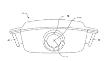
図面を詳細に参照すると、同様の参照符号は、同様の構造を一貫して表す。図1〜図7は、本開示の一実施形態にかかる装置(一般的に参照符号10が付与される)を示す。装置10は、被験者(例えば患者)の方向へ、または、被験者へ、光を導き、被験者から反射または屈折された光を受け、受けた光を分析して、被験者が脳損傷を負っているか否かを決定するように構成されている。このような機能を達成するために、装置10は、少なくとも二つまたは四つあるいはそれ以上の、離間して配置されたライト12を、装置本体の外面(例えば前面)に備えている(図1および2参照)。装置本体は、第1または上の側面または表面、相対する第2または底の側面または表面、前または第1の面、および、相対する後ろまたは第2の面、を備えている。使用時、前の面は、損傷を受けた可能性がある被験者に向けられ、後ろの面は、装置を支持する人間に向けられる。
Referring to the drawings in detail, like reference numerals consistently represent like structures. 1-7 show an apparatus (generally given reference numeral 10) according to one embodiment of the present disclosure. The
ライト12は、例えば、点灯されたときに被験者の注意を惹くようデザインされた発光ダイオード(LED)として構成し得る。それぞれのライト12は、異なる色(例えば、黄色、オレンジ、赤、および緑)を表示するように点灯することができる。ライト12は、同時にまたは異なるタイミング(例えば、順に、または、被験者にランダムに感じられる状態)で点灯させることができる。例えば、ライト12は、図2において番号1、2、3、および4で示す順に点灯することができる。このように、動作時に、ライト12は、被験者または患者が特定のタスクまたはルーチンを達成するために眼で捕捉しまたは追うように要求される、動く固視ターゲットとして機能する。試験の被験者または患者がターゲットの順序を予測して結果を操作することを防ぐために、衝動のトリガーは、少なくとも二つの変数にしたがって変化させることができる。その二つの変数とは、1)点灯するライトの位置(L0,・・・,L4)、および/または、2)ライトの点灯の時間間隔(t0,・・・,t0+n)。被験者は、単純に、点灯パターンを追っても良いし、被験者がパターンを追うことを指示または援助するために、一つまたはそれ以上の他の信号(例えば可聴信号)が与えられても良い。
The
ライト12は、ターゲット14を囲むように、または、ターゲット14の近くに位置するように、配置されても良い。一つの実施形態において、ターゲット14は、スマイリーフェイスの画像を含んでいても良いし、または、スマイリーフェイスの形状に点灯するライトであっても良い。しかし、ターゲット14は、ここに図示され説明されたものと正確に同じサイズまたは形状に限定されるものではない。ターゲット14は、装置10の外部から、装置10の開口または窓15を通して視認可能であっても良い。開口15の直径は、それぞれのライト12の直径と正確に同じであっても良いし、それぞれのライト12の直径よりも少なくともわずかに大きくても良い。一実施形態において、ライト12とターゲット14の点灯は、患者のサッカード潜時を測定するために同期させることができる。
The
装置10は、携帯可能かつ容易に運搬および収納ができるように、大きさ、形状、および/または、構成が決められていても良い。例えば、装置10は、手持ちが可能であるように、または、人間が手で簡単に持ち上げることができる程度に小型に、形成することができる。装置10は、小児科医、コーチ、医師等によって用いることができる。例えば、装置10は、自動車事故の直後に、または、頭部関連の負傷の直後に運動場において、あるいは、仲間の兵士が負傷した後の戦場で兵士が使用する場合に、役立つ可能性がある。一実施形態において、対象者の緊急の要求が満たされた後(例えば、対象者の脊髄に損傷が無いことが確認された後)、装置10を、患者が頭部または脳に損傷を負っているか否かを確かめるために用いることができる。例えば、一人の人間が装置10を支持して、二人目の人間(怪我をした可能性がある人間)がライト12とターゲット14を見られるようにすることができる。動作中に、一実施形態において、装置10と前記二人目の人間(怪我をした可能性がある人間)との間の距離は、使用者の眼がライト12および/またはターゲット14を追うときに感知可能な距離を移動するように、例えば約400mmまたは1フット程度に十分に小さくすることができる。前記一人目の人間は、装置10の外部の一つまたは複数のハンドル40(例えば、装置10の対向する側面に設けられたハンドル)で、装置10を保持することができる。各ハンドル40は、装置10の側面から外側へ突出させることができる。前記二人目の人間は、前記一人目の人間から、例えば、ライト12および/またはターゲット14を見て、ライト12および/またはターゲット14がそれぞれに点灯するのを追うように、命令されても良い。
The
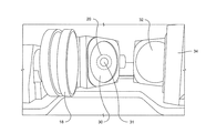
本開示の一実施形態において、米国特許第6,027,216号に開示された複屈折スキャン方法を、装置10によって最適化または改良することができる。一実施形態において、装置10内で、光源28(例えばレーザ)が、低出力(例えば50mW未満)で、分岐し、偏光されたレーザ光のビームを生成するようにしても良い。光源28で生成された光の少なくとも一部は、傾斜し、回転する鏡18(すなわち「第1の鏡」)へ導かれ、第2の鏡30(図7参照)上にスキャン20を実現する。ここで鏡を参照する際の「第1」、「第2」、「第3」等は、光源28からの光または怪我をした可能性がある人間からの光が進む順序、鏡で反射する順序、または鏡に到達する順序と、何ら関係はない。スキャン20は、光源28からの真っ直ぐなまたは「スポットの」ライトビームが、回転する第1の鏡18に入射することの結果として、被験者にとって円状に見えても良い。言い換えると、スキャン20は、光源28からのスポットが、使用者にとってリングに見えるように十分な割合で払いのけられるので、リングの錯覚を引き起こすことができる。スキャン20は、被験者の片目または両目へ向けて導かれ、スキャン20およびターゲット14のスマイリーフェイス20は、被験者によって同時に視認できる。ターゲット14のスマイリーフェイスが被験者によって適切に観察されれば、スキャン20は消失して眼の神経繊維に当たる。一実施形態において、1回の光の通過の間に偏光を二度変更することができる。
In one embodiment of the present disclosure, the birefringence scanning method disclosed in US Pat. No. 6,027,216 can be optimized or improved by the
第1の鏡18は、コストを下げるために、質量的に均衡のとれたデザインとしても良い。第1の鏡18は、少なくともわずかに凹んだ前面を有していても良い。第1の鏡18は、光源28からの光が進む面に対して、少なくともわずかに傾いていても良い。第1の鏡18は、第1の鏡18を選択的に回転またはスピンさせるよう構成されたモータ42に、操作可能に取り付けられていても良い。第2の鏡30は、ドーナツ型(toroidal)の湾曲を有していても良い。より具体的には、第2の鏡30は、垂直軸に比較して水平軸において異なる湾曲半径を持った(両方とも、湾曲は凹状である)、凹形状を有していても良い。第2の鏡30は、例えばその中央に、第1の開口または穴31を有していても良い。第1の開口31は、円形であっても良い。ターゲット14のスマイリーフェイスは、装置10が被験者に対して正しく位置決めされたときに、第1の開口31に一致するか、または、被験者によって第1の開口31の上または内部に見えるようにしても良い。一実施形態において、第1の開口31は、その上にターゲット14が配置されるガラスの表面であっても良い。第2の鏡30は、第2の開口または穴を、例えばその中心に、備えていても良い。第2の開口は、光ビームの少なくとも一部が、そこを通過することを可能とする(図4参照)。
The
被験者は、ターゲット(例えばターゲット14)を装置10内または装置10上で固視する。これにより、サークルの中心を、網膜固視のポイントに合わせることができ、レーザ光をスキャン中に網膜上にフォーカスさせることができる。装置10から発する光は、被験者の網膜の神経細胞を通過し、光は、網膜構造およびスキャン時の眼球アライメントによって変更され得る。入射光は、その後、眼底で再反射され、眼の光学システムを通過して装置10へ戻る。
The subject gazes at the target (for example, the target 14) in or on the
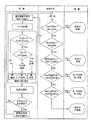
一実施形態において、戻り光は、装置10の開口15を通って入射し、装置10内で反射され、検出ブロック38内の立体視(haploscopic)ナイフエッジプリズムまたは鏡群へ導かれて、右目信号と左目信号とに分離される。それぞれのビームパスは、左目偏光アナライザおよび右目偏光アナライザ、または、検出ブロック38内の一つまたは複数の偏光高感度検出器へ導かれる。偏光の変化は、電気信号に変換され、オンボードのソフトウエアおよび独自のアルゴリズムを用いたリアルタイム分析のために二値化される。図8に、そのようなアルゴリズムの一例を示す。一実施形態において、プリズムおよび鏡として、光を二つの異なる方向に導くために互いに90度に配置された二つの鏡を用いることができる。
In one embodiment, the return light is incident through the
図4は、本開示の一実施形態にかかる光の経路を示す。例えば、光源28から出射された光を、ビームスプリッタ22に導くようにしても良い。光が、光源28とビームスプリッタ22との間で、二つ以上の光学素子の間または二つ以上の光学素子を通過して進むようにしても良い。一実施形態において、ビームスプリッタ22、またはパワースプリッタは、入射する光ビーム(例えばレーザビーム)を、二本以上のビームに分割するよう構成された光学素子である。前記二本以上のビームは、同じ光パワー(optical power)を有していても良いし、光パワーが互いに異なっていても良い。
FIG. 4 illustrates a light path according to an embodiment of the present disclosure. For example, the light emitted from the
ビームスプリッタ22は、透明または半透明であっても良い。ビームスプリッタ22は、光源28が光の経路またはビームを送る方向に対して角度(例えば約45度)を持って延びる平面を定義しても良い。ビームスプリッタ22から反射された光が、第3の鏡36に入射するようにしても良い。第3の鏡36で反射された光は、第2の鏡30の第2の開口を通過するように、第4の鏡32に入射しても良い。第4の鏡32で反射された光は、第5の鏡34へ入射するようにしても良い。第5の鏡34で反射された光は、回転する第5の鏡18へ入射しても良い。第1の鏡で反射された光が、戻り経路において、第5の鏡34へ、その後第4の鏡32へ、さらにその後第2の鏡30へ導かれ、開口15から被験者へと出射するようにしても良い。一実施形態において、第3の鏡36、第4の鏡32、および第5の鏡34等の、ここに開示されている技術のいくつかの鏡は、誘電体反射鏡または金の鏡のいずれかで構成することができる。誘電体反射鏡は、散乱が原因で多くの迷光を生じることがある。そのような状況においては、金の鏡を用いることが望ましい。金の鏡は、金で形成された反射面を有していても良い。金の鏡を構成するために用いられる材料の大部分は、精密な下地と研磨された平坦な表面を有するガラスであっても良い。この平坦な表面は、薄い金属被膜を有していても良く、その最表面の被膜の金属は金である。金の鏡の反射特性は、前記金の被膜によって決定づけられる。
The
図4に示すように、被験者から装置10へ戻る光は、装置10または光源28から発せられる光の逆の経路を進むことが一般的である。しかしながら、第3の鏡36で反射した光は、ビームスプリッタ22を通過して、偏光高感度検出器を内部に備えた検出ブロック38へ進む。
As shown in FIG. 4, the light returning from the subject to the
一実施形態において、ソフトウエア分析は、周波数成分を特定するために、コンピュータによって二値化信号のフーリエ解析を行うことから開始される。いずれかの眼(片眼)への戻り光の周波数が、その眼を通る経路中で二倍になっていると判定された場合、その眼の窩の中心固視が確認される。両眼において中心固視が同時に検出された場合、被験者は、正常な両眼アライメントと正常な両眼視野を持つとされる。中心固視が片眼または両眼で検出されなかった場合、被験者は、アライメントの失調を有すると判定される。 In one embodiment, software analysis begins with performing a Fourier analysis of the binarized signal by a computer to identify frequency components. If it is determined that the frequency of the return light to any eye (one eye) is doubled in the path through that eye, central fixation of the fovea of that eye is confirmed. If central fixation is detected simultaneously in both eyes, the subject is assumed to have normal binocular alignment and normal binocular visual field. If central fixation is not detected with one eye or both eyes, the subject is determined to have an alignment failure.
米国特許第6,027,216号に開示された装置と比較して、ここに開示されている技術は、例えば瞳孔間距離(inter-pupillary distance:IPD)、照明レベル、焦点感度(focus sensitivity)、サッカード潜時、およびソフトウエア改良等の、一つ以上の変更を含み得る。 Compared to the device disclosed in US Pat. No. 6,027,216, the techniques disclosed herein are, for example, inter-pupillary distance (IPD), illumination level, focus sensitivity. May include one or more changes, such as saccade latency and software improvements.
IPD:従来技術の小児視野スキャナ(Pediatric Vision Scanners: PVS)は、50mmのIPDに適合させることができる。しかし、平均的な若年成人のIPDは63mmである。IPDを大きくすると、両方の射出瞳の幅が40mmで、鼻端間で23mmだけ離間するように、装置内での差分偏光(differential polarization)センサと開口との再配置が必要となる。この光学機械的な変更により、ここに開示する構成で、眼からの光をより多く捕捉することが可能となり、子供(5歳における最小のIPDが40mm)に対する診断を可能としつつ、SN比を向上させ、診断性能を改善することができる。ここでの開示の一実施形態において、装置10は、単一の装置で大人と子供の両方に対するIPD(すなわち、二つの位置)を実現するように変形することが可能である。他の実施形態において、一つの装置10が大人のIPDに合わせて設計され、二つ目の装置10が子供のIPDに合わせて設計するようにしても良い。
照明レベル:人間の加齢と共に、無症候性の水晶体混濁化や錐体光受容体の神経線維層の厚みの減少によって、眼の反射率は次第に減少する傾向がある。これにより、装置にとって利用可能な反射光の量は減少する。従来のPVSは、きわめて低い光レベル(例えば240μW)を使用し、固定レーザによっても膨大な暴露が可能となる。現在の安全基準においては、照射強度を向上させることにより戻り光の強さを改善するための、十分な余地がある。この目的を達成するための一つの方法は、ビームスプリッタを変更することである。従来の装置では、主ビームスプリッタ(50:50タイプ)は、レーザからのエネルギーの半分と、眼から戻るエネルギーの半分とを捨て去る(ダンプする)。これは、測定を行うためには、行きと戻りの光経路は同軸でなければならないので、必要な光損失である。一実施形態においては、ここに開示する装置は、国際電気標準会議(IEC)のレーザ安全性限界内を維持しながら、より明るい光源のレーザへ移行すると共に、偏光されたレーザのエネルギーのより多くの部分を捨て去ることにより、戻り光の経路を改良する。ここに開示する装置において、90:10のビームスプリッタ22を用いることにより、レーザエネルギー(例えば、光源28で生成された光)の90%を捨て去ることができるが、眼からのエネルギー(例えば、被験者の眼からの戻り光)の90%が検出ブロック38内のセンサへ戻ることを可能とする。つまり、ここに開示するビームダンプデザインは、およそ10%を反射しつつ、光源28からのエネルギーのおよそ90%を透過または抑制する。ビームダンプデザインの一実施形態は、互いに離間して配置された第1の構成要素24および第2の構成要素26を含む。第1・第2の構成要素24・26は、光源28から出射されビームスプリッタ22を通過する光を、廃棄または吸収する。このデザイン改良を実現するためには、光が戻り経路に沿って後方散乱しないように、ビームダンプの改良が必要となる。そのようなデザインは、被験者が追加のライトに気付くことなく、より強力な(より明るい)光源28の使用を可能とする。
IPD: Prior art Pediatric Vision Scanners (PVS) can be adapted to a 50 mm IPD. However, the average young adult IPD is 63 mm. Increasing the IPD requires repositioning of the differential polarization sensor and the aperture in the device so that both exit pupils are 40 mm wide and 23 mm apart between the nose ends. This opto-mechanical change makes it possible to capture more light from the eye with the configuration disclosed herein, while enabling diagnosis for children (minimum IPD at 5 years of age is 40 mm) while reducing the signal-to-noise ratio. Can improve and improve diagnostic performance. In one embodiment of the disclosure herein, the
Illumination level: As humans age, the reflectance of the eye tends to gradually decrease with asymptomatic lens opacification and a decrease in the thickness of the nerve fiber layer of the cone photoreceptor. This reduces the amount of reflected light available to the device. Conventional PVS uses very low light levels (eg, 240 μW) and can be exposed extensively even with fixed lasers. In current safety standards, there is enough room to improve the intensity of the return light by increasing the illumination intensity. One way to achieve this goal is to change the beam splitter. In conventional devices, the main beam splitter (50:50 type) throws away (dumps) half of the energy from the laser and half of the energy returning from the eye. This is a necessary optical loss because the outgoing and return optical paths must be coaxial in order to make measurements. In one embodiment, the apparatus disclosed herein transitions to a brighter laser while maintaining within the International Electrotechnical Commission (IEC) laser safety limits and uses more of the energy of the polarized laser. The path of the return light is improved by throwing away the part. In the apparatus disclosed herein, the 90:10
焦点感度:戻り光の焦点不良を検出することにより、元の小児用装置の性能が向上された。ここに開示する装置においては、その目的は、眼の焦点が合っていない場合でも、非侵襲で固視安定性とサッカード速度とを分析することにある。特に、ここに開示する装置は、矯正されていない屈折異常を持つ人間の指標基準(index metrics)を正しく評価することを可能とする。器具の感度の焦点ぼけを抑制するために、レンズアセンブリおよび少なくとも一つの開口は、より多くの戻り光を得るために、変更可能である。レンズの大きさを増大させることで、背景信号レベルを増加させることができるであろう。ここに開示する光学システムは、背景信号を制御するために、追加的な特徴や手段を有していても良い。 Focus sensitivity: The performance of the original pediatric device was improved by detecting poor focus of the return light. In the device disclosed herein, the objective is to analyze non-invasive fixation stability and saccade velocity even when the eye is out of focus. In particular, the device disclosed herein allows for the correct evaluation of human index metrics with uncorrected refractive errors. In order to reduce the instrument sensitivity defocus, the lens assembly and at least one aperture can be modified to obtain more return light. Increasing the size of the lens could increase the background signal level. The optical system disclosed herein may have additional features and means for controlling the background signal.
従来の装置では、背景信号の最も大きい原因は、器具内部で生成されていた。ここに開示する装置および/または方法は、より厳密な全体としての迷光制御スキームへ移行することにより、背景信号を抑制する。ここに開示する装置および/または方法によれば、迷光の背景信号先見的な方法は、(1)背景信号とデータ信号との同期を強化するための位置符号化モータ(position-encoded motor)の利用、(2)開口の精密な位置合わせ、および(3)ビームダンプの再構築、を含む。一実施形態において、ビームダンプは、開口に関して、検出ブロックからできるだけ離して移動することができる。ここに開示する装置および/または方法は、背景信号レベルを少なくとも10倍減少させることができ、眼から戻るビームのサイズを著しく増大させることができる。 In the conventional device, the largest cause of the background signal is generated inside the instrument. The apparatus and / or method disclosed herein suppresses background signals by moving to a more strict overall stray light control scheme. In accordance with the apparatus and / or method disclosed herein, the background signal foresight method of stray light includes (1) a position-encoded motor for enhancing the synchronization of the background signal and the data signal. Use, (2) precise alignment of the aperture, and (3) reconstruction of the beam dump. In one embodiment, the beam dump can be moved as far as possible from the detection block with respect to the aperture. The apparatus and / or method disclosed herein can reduce the background signal level by at least 10 times and can significantly increase the size of the beam returning from the eye.
サッカード潜時:従来の網膜複屈折スキャン(RBS)装置は、サッカード潜時の測定を行っていない。本開示の一実施形態は、例えば、表示画面(viewing area)の周辺に、現在のスキャンビームを、複数(例えば四つないしは六つ)の均等に配置されたLED12で囲むことを含む(例えば図1参照)。各LEDは、異なる色(赤、緑、黄、オレンジ)を投射または表示できる。図2は、装置10の一実施形態における各LEDを識別するための番号を含む。当業者であれば、そのような番号は、便宜のためおよび説明を分かりやすくするために含まれており、実際の装置に含まれているわけではないことを理解できるであろう。
Saccade latency: Conventional retinal birefringence scanning (RBS) devices do not measure saccade latency. One embodiment of the present disclosure includes, for example, surrounding the current scan beam with a plurality (eg, four or six) of equally spaced
潜時をテストするために、被験者または患者は、可聴性または視認可能な合図を受けて、(単一または順次に)点灯される周辺LED(単一または順次)を見て、その後すぐに、中心固視ターゲット14を再び凝視する。そして、最初の周辺の合図の発行から中心固視の検出までの潜時が、記録される。サッカード潜時は、タスクに応じて、250msから400msの間であると見込まれるので、「一周」全体の潜時は、最小で500msであろう。従来の小児用RBS装置は、10回以内のスキャンで、または、約100ms以内で、中心固視を検出できるように、スキャン周波数が100Hzである。中心固視の暫定解像度をさらに向上させるために、基本的な工学手法にしたがって、本開示の装置のモータ速度を向上させても良い。
To test latency, the subject or patient receives an audible or visible cue, looks at the peripheral LEDs (single or sequential) that are lit (single or sequential), and immediately thereafter. Gaze at the
ソフトウエア改良:従来のソフトウエアは、最大5秒のテストを可能とし、単眼または両眼の固視安定性の全範囲、両眼視能(binocularity)、およびサッカード潜時のテストをサポートしていない。固視安定性およびサッカード潜時のより完全な分析に適合するように、本開示のソフトウエアは、単眼または両眼の条件下で、拡張された信号捕捉を許容する。本開示の一実施形態のソフトウエアは、以下のそれぞれを指示するための一連のテストを実行していく。
−単眼の固視安定性(10秒)、および
−サッカード潜時タスク(15秒)。
Software improvements: Traditional software allows testing up to 5 seconds and supports the full range of monocular or binocular fixation stability, binocularity, and saccade latency testing. Not. To accommodate a more complete analysis of fixation stability and saccade latency, the software of the present disclosure allows extended signal capture under monocular or binocular conditions. The software of an embodiment of the present disclosure performs a series of tests to indicate each of the following.
-Monocular fixation stability (10 seconds), and-saccade latency task (15 seconds).
データ記憶装置およびテスト時間は、図7に示すように、テストの長さと高速フーリエ変換(FFT)の暫定解像度とを考慮する。 The data storage and test time take into account the test length and the provisional resolution of the fast Fourier transform (FFT), as shown in FIG.
他の変形:前記の変形例に関連する一つの変形は、光学パワーを向上させるための第2の鏡30の創作または使用である。第2の鏡30は、凹面鏡を形成するために表面に曲面を有し、米国特許第6,027,216号の装置における迷光の主要因を排除することができる。従来のシステムにおいて、屈折レンズ(反射を抑制するためにコーティングされていたとしても)は、受光側へ戻り得る反射を生じる。本開示の装置では、円環状の第2の鏡30を備えることができ、従来技術の折り畳み鏡(fold mirror)およびレンズは不要である。行きと戻りの光に共通な屈折面は存在せず、眼からの所望の光のみが、センサ受光器へ戻る。制御すべき迷光反射は存在しない。この変更は、システム性能を大きく向上させ、構成要素の交換によって達成される。
Other variants: One variant associated with the previous variant is the creation or use of the
上述のシステムおよび/または方法の少なくとも一つが、ソフトウエアによって実装され、または、ソフトウエアを利用する。このソフトウエアは、例えば、少なくとも一つのコンピュータ装置1510(図12参照)において実行されるモジュールである。もちろん、ここに述べるモジュールは、様々な機能を説明するものであり、いずれの実施形態の構成または機能をも制限するものではない。むしろ、様々なモジュールの機能は、様々に分割することができ、様々な設計を考慮して、より多くのまたはより少数のモジュールによって実行することができる。 At least one of the systems and / or methods described above is implemented by or utilizes software. This software is, for example, a module executed in at least one computer device 1510 (see FIG. 12). Of course, the modules described here are for describing various functions and are not intended to limit the configuration or function of any of the embodiments. Rather, the functions of the various modules can be divided differently and can be performed by more or fewer modules considering different designs.
コンピュータ装置1510のそれぞれは、例えば、一つ以上の記憶装置1513に非一時的に格納されたコンピュータ可読命令(すなわちコード)等の命令を処理するよう設計された一つ以上の処理装置1511を備えることができる。命令を処理することにより、処理装置1511は、ここに開示された一つ以上のステップおよび/または機能を実行することができる。それぞれの処理装置は、実機であっても良いし、仮想であっても良い。処理パワーを向上させるために、マルチプロセシングシステムにおいて、マルチプロセシングユニットが、コンピュータ実行可能な命令を実行することができる。記憶装置1513は、任意の種類の非一時的な記憶装置(例えば、光学記憶装置、磁気記憶装置、半導体記憶装置等)であり得る。記憶装置1513は、取り外し可能であっても取り外し不可能であっても良く、磁気ディスク、磁気テープまたはカセット、CD−ROM、CD−RW、DVD、あるいは、情報を格納するために用いられる任意の媒体であっても良い。あるいは、例えばネットワークまたはインターネットを介してアクセスされる記憶装置など、一つ以上のリモート記憶装置に命令を格納しても良い。
Each of the
各コンピュータ装置1510は、追加的に、メモリ1512、一つ以上の入力コントローラ1516、一つ以上の出力コントローラ1515、および/または一つ以上の通信接続1540を備えていても良い。メモリ1512は、揮発性メモリ(例えば、レジスタ、キャッシュ、RAM等)、不揮発性メモリ(例えば、ROM、EEPROM、フラッシュメモリ等)、または、これらのいくつかの組み合わせであっても良い。少なくとも一つの実施形態において、メモリ1512は、ここに記載された技術を実現するためのソフトウエアを格納することができる。
Each
例えばバス、コントローラ、またはネットワーク等の内部接続機構1514が、プロセッサ1511、メモリ1512、記憶装置1513、入力コントローラ1516、出力コントローラ1515、通信接続1540、およびその他の装置(例えばネットワークコントローラ、サウンドコントローラ等)を含むコンピュータ装置1510の構成要素を動作可能に結合することができる。出力コントローラ1515は、一つ以上の出力装置1520(例えば、モニタ、テレビ、モバイル装置のスクリーン、タッチディスプレイ、プリンタ、スピーカ等)へ、出力コントローラ1515が表示装置1520上の表示を変更できるような状態で(例えば、モジュールの実行に応じて)、動作可能に(例えば、有線または無線接続を介して)結合することができる。入力コントローラ1516は、入力装置1530(例えば、マウス、キーボード、タッチパッド、スクロールボール、タッチディスプレイ、ペン、ゲームコントローラ、音声入力装置、スキャン装置、デジタルカメラ等)へ、ユーザからの入力を受信できる状態で、動作可能に(例えば、有線または無線接続を介して)結合することができる。
For example, an
通信接続1540は、通信媒体上での、他のコンピュータエンティティに対する通信を可能とする。通信媒体は、コンピュータ実行可能命令、音声または画像情報、または他のデータ等の情報を、変調されたデータ信号で伝達する。変調されたデータ信号は、その信号中の情報を符号化するように、データ信号の特性の一つ以上が、設定または変更された信号である。一例として、ただし限定的ではなく、通信媒体は、電気的、光学的、RF、赤外線、音声、または他の伝送媒体で実現される、有線または無線技術を含む。
図12は、コンピュータ装置1510、出力装置1520、および入力装置1530を、特定を容易にする目的のみで、別個の装置として図示する。しかし、コンピュータ装置1510、表示装置1520、および/または入力装置1530は、別個の装置であっても良いし(例えば、モニタまたはマウスにワイヤで接続されたパーソナルコンピュータ)、単体の装置(例えば、スマートフォンやタブレットのように、タッチディスプレイを備えたモバイル装置)に統合されていても良いし、装置の任意の組み合わせ(例えば、タッチスクリーン表示装置に動作可能に結合されたコンピュータ装置、単体の表示装置よび入力装置に接続された複数のコンピュータ装置、等)であっても良い。コンピュータ装置1510は、例えばネットワーク化されたサーバ群、クラスタ化されたサーバ環境、または、遠隔コンピュータ装置で実行されるクラウドサービスのような、一つ以上のサーバ群であっても良い。
FIG. 12 illustrates
当業者であれば、上述の実施形態に対して、その広い発明概念から乖離することなく、変更を加えることができることは理解できるであろう。例えば、当業者に理解されるように、上記した方法のいずれかにおいて、ステップまたは実行順序を変更することが可能であり、異なる順序で発生し得る。したがって、この開示は、上記の特定の実施形態に限定されるものではなく、添付の請求項に定義されるように、本開示の精神と範囲の中でなされる変更を含むことが意図されている。
Those skilled in the art will appreciate that changes can be made to the above-described embodiments without departing from the broad inventive concept. For example, as will be appreciated by those skilled in the art, in any of the methods described above, the steps or execution order can be changed and can occur in different orders. Accordingly, this disclosure is not intended to be limited to the particular embodiments described above, but is intended to include modifications made within the spirit and scope of this disclosure as defined in the appended claims. Yes.
Claims (30)
ハウジングの内部に配置され、前記ハウジングの窓から、前記ハウジングの外部にある被験者の少なくとも一つの網膜上に光ビームを出射するように構成された光源と、
前記ハウジングの外面に配置された一つまたは複数のライトと、
一つまたは複数の合図のシーケンスを出力するよう構成されたコントローラであって、前記シーケンス内のそれぞれの合図は、前記一つまたは複数のライトと、前記ハウジングの外部にある被験者に向けた光ビームと同軸に構成された固視ターゲットとのいずれかに対応するコントローラと、
前記ハウジング内に配置され、前記被験者の少なくとも一つの網膜から反射された光を前記ハウジングの窓を通して検出する、一つまたは複数の検出器とを備え、
前記コントローラは、前記合図のシーケンスにおける少なくとも一つの合図の出力と、被験者による固視または固視喪失のいずれかとの間の少なくとも一つの遅れに対応する少なくとも一つの時間間隔を決定するよう構成され、前記固視または固視喪失は、前記被験者の少なくとも一つの網膜から反射された光に少なくとも部分的に基づいて決定される、装置。 A device for measuring saccade latency,
Disposed within the housing, through a window of the housing, a light source configured to emit a light beam on at least one of the retina of a subject that is outside of the housing,
One or more lights disposed on an outer surface of the housing ;
A controller configured to output a sequence of one or more cues, each cues in the sequence comprising a light beam directed to the subject outside the housing and the one or more lights. And a controller corresponding to one of the fixation target configured coaxially ,
Wherein disposed in the housing, the light reflected from at least one of the retina of the subject you detected through a window of the housing, and a one or more detectors,
The controller is configured to determine at least one time interval corresponding to at least one delay between the output of at least one cue in the sequence of cues and either fixation or loss of fixation by the subject; The apparatus, wherein the fixation or loss of fixation is determined based at least in part on light reflected from at least one retina of the subject .
前記ハウジング内に配置された第2の鏡とをさらに備え、
前記第1の鏡は、その少なくとも一部が回転するように構成されたことにより、前記第2の鏡上でのスキャンを生じさせ、前記第2の鏡は、前記第1の鏡から反射された光を受けて、受けた光を前記ハウジングの前記窓を通じて反射するよう構成された、請求項1に記載の装置。 A first mirror disposed within the housing and configured to reflect light received from the light source ;
A second mirror disposed in the housing ,
The first mirror is configured such that at least a part of the first mirror rotates, thereby causing a scan on the second mirror, and the second mirror is reflected from the first mirror. The apparatus of claim 1, wherein the apparatus is configured to receive received light and reflect the received light through the window of the housing .
ハウジングの内部に配置された光源により、前記ハウジングの窓から、前記ハウジングの外部にある被験者の少なくとも一つの網膜上に光ビームを出射するステップと、 Emitting a light beam from a window of the housing onto at least one retina of a subject outside the housing by a light source disposed within the housing;
コントローラにより、一つまたは複数の合図のシーケンスであって、当該シーケンス内のそれぞれの合図が、前記一つまたは複数のライトと、前記ハウジングの外部にある被験者に向けた光ビームと同軸に構成された固視ターゲットとのいずれかに対応する合図のシーケンスを出力するステップと、 A sequence of one or more cues by a controller, each of the cues in the sequence being configured coaxially with the one or more lights and a light beam directed to a subject outside the housing. Outputting a sequence of cues corresponding to any of the fixed fixation targets;
前記ハウジング内に配置された一つまたは複数の検出器により、前記被験者の少なくとも一つの網膜から反射された光を前記ハウジングの窓を通して検出するステップと、 Detecting light reflected from at least one retina of the subject through a window of the housing with one or more detectors disposed within the housing;
前記コントローラにより、前記合図のシーケンスにおける少なくとも一つの合図の出力と、被験者による固視または固視喪失のいずれかとの間の少なくとも一つの遅れに対応する少なくとも一つの時間間隔を決定するステップとを含み、 Determining, by the controller, at least one time interval corresponding to at least one delay between the output of at least one cue in the sequence of cues and either fixation or loss of fixation by the subject. ,
前記固視または固視喪失は、前記被験者の少なくとも一つの網膜から反射された光に少なくとも部分的に基づいて決定される、方法。 The fixation or loss of fixation is determined based at least in part on light reflected from at least one retina of the subject.
前記第1の鏡は、その少なくとも一部が回転するように構成されたことにより、前記ハウジング内に配置された第2の鏡上でのスキャンを生じさせ、前記第2の鏡は、前記第1の鏡から反射された光を受けて、受けた光を前記ハウジングの前記窓を通じて反射するよう構成された、請求項13に記載の方法。The first mirror is configured such that at least a part of the first mirror rotates, thereby causing a scan on a second mirror disposed in the housing, and the second mirror includes the first mirror. The method of claim 13, configured to receive light reflected from a mirror and reflect the received light through the window of the housing.
窓を有するハウジングと、 A housing having a window;
前記ハウジングの内部に配置され、光ビームを発するように構成された光源であって、前記光ビームの少なくとも一部が、前記窓を通って、前記被験者の少なくとも一つの眼の少なくとも一つの網膜上に達するよう構成された光源と、 A light source disposed within the housing and configured to emit a light beam, wherein at least a portion of the light beam passes through the window and onto at least one retina of at least one eye of the subject. A light source configured to reach
前記ハウジング内に配置され、前記窓を通した少なくとも一つの網膜からの、前記光ビームの一つまたは複数の反射を検出するように構成された一つまたは複数の光検出器と、 One or more photodetectors disposed within the housing and configured to detect one or more reflections of the light beam from at least one retina through the window;
前記ハウジングの外面に配置された一つまたは複数のライトと、 One or more lights disposed on an outer surface of the housing;
前記ハウジングの外面の窓に表れるよう構成されたターゲットと、 A target configured to appear in a window on the outer surface of the housing;
前記一つまたは複数のライトを公知のシーケンスで点灯し、前記被験者の少なくとも一つの眼の固視を決定するために、前記少なくとも一つの網膜からの、前記一つまたは複数の光ビームの反射を評価し、前記少なくとも一つの眼の固視または固視喪失が達成される時間を、ターゲットと前記一つまたは複数のライトの点灯の変化とに関連付けて決定するよう構成されたコントローラとを備えた、装置。 The one or more lights are lit in a known sequence, and the reflection of the one or more light beams from the at least one retina is determined to determine fixation of at least one eye of the subject. A controller configured to evaluate and determine a time at which fixation or loss of fixation of the at least one eye is achieved in relation to a target and a change in lighting of the one or more lights ,apparatus.
神経学的スクリーニング装置のハウジングの窓を、被験者の少なくとも一つの眼の前に配置するステップと、 Positioning the window of the housing of the neurological screening device in front of at least one eye of the subject;
前記ハウジングの内部に配置された光源により、その少なくとも一部が、前記窓を通って、前記被験者の少なくとも一つの網膜上に達するよう構成された光ビームを発するステップと、 Emitting a light beam configured such that at least a portion thereof passes through the window and onto at least one retina of the subject by a light source disposed within the housing;
前記ハウジング内に配置された光検出器により、前記窓を通した少なくとも一つの網膜からの、前記光ビームの一つまたは複数の反射を検出するステップと、 Detecting one or more reflections of the light beam from at least one retina through the window by a photodetector disposed in the housing;
コントローラにより、前記ハウジングの外側に配置された一つまたは複数のライトを公知のシーケンスで点灯するステップと、 Lighting one or more lights arranged outside the housing by a controller in a known sequence;
前記コントローラにより、前記被験者の少なくとも一つの眼の固視を決定するために、前記少なくとも一つの網膜からの、前記一つまたは複数の光ビームの反射を評価するステップと、 Evaluating, by the controller, reflection of the one or more light beams from the at least one retina to determine fixation of at least one eye of the subject;
前記コントローラにより、前記少なくとも一つの眼の固視または固視喪失が達成される時間を、前記ハウジングの外面の窓に表れるよう構成されたターゲットと前記一つまたは複数のライトの点灯の変化とに関連付けて決定するステップとを含む、方法。 The time at which fixation or loss of fixation of the at least one eye is achieved by the controller is defined as a target configured to appear in a window on the outer surface of the housing and a change in lighting of the one or more lights. And determining in association.
前記コントローラにより、前記比較に少なくとも部分的に基づいて、脳機能障害を分析するためのテストを前記被験者が合格するか否かを決定するステップとをさらに含む、請求項28に記載の方法。 29. The method of claim 28, further comprising: determining, by the controller, whether the subject passes a test for analyzing brain dysfunction based at least in part on the comparison.
Applications Claiming Priority (3)
| Application Number | Priority Date | Filing Date | Title |
|---|---|---|---|
| US201662278196P | 2016-01-13 | 2016-01-13 | |
| US62/278,196 | 2016-01-13 | ||
| PCT/US2017/013116 WO2017123705A1 (en) | 2016-01-13 | 2017-01-12 | Method and apparatus for fixation, alignment, and/or saccadic measurements to identify and/or track brain function |
Publications (2)
| Publication Number | Publication Date |
|---|---|
| JP2018504957A JP2018504957A (en) | 2018-02-22 |
| JP6407442B2 true JP6407442B2 (en) | 2018-10-17 |
Family
ID=59311990
Family Applications (1)
| Application Number | Title | Priority Date | Filing Date |
|---|---|---|---|
| JP2017534772A Active JP6407442B2 (en) | 2016-01-13 | 2017-01-12 | Fixation, alignment and / or impulsiveness measuring method and apparatus for identifying and / or tracking brain function |
Country Status (5)
| Country | Link |
|---|---|
| EP (1) | EP3232902A4 (en) |
| JP (1) | JP6407442B2 (en) |
| AU (1) | AU2017203522B2 (en) |
| CA (1) | CA2971330C (en) |
| WO (1) | WO2017123705A1 (en) |
Families Citing this family (2)
| Publication number | Priority date | Publication date | Assignee | Title |
|---|---|---|---|---|
| JP7140072B2 (en) * | 2019-07-29 | 2022-09-21 | 株式会社デンソー | Eyeball index detection device, eyeball index detection method, eyeball index detection program |
| WO2023077220A1 (en) * | 2021-11-02 | 2023-05-11 | Anthony Lemmo | Visual brain therapy device |
Family Cites Families (21)
| Publication number | Priority date | Publication date | Assignee | Title |
|---|---|---|---|---|
| US4838681A (en) * | 1986-01-28 | 1989-06-13 | George Pavlidis | Method and means for detecting dyslexia |
| DE9205870U1 (en) * | 1992-05-06 | 1992-09-17 | J.D. Moeller Optische Werke Gmbh, 2000 Wedel, De | |
| US5673097A (en) * | 1996-04-15 | 1997-09-30 | Odyssey Optical Systems Llc | Portable scanning laser ophthalmoscope |
| US6299307B1 (en) * | 1997-10-10 | 2001-10-09 | Visx, Incorporated | Eye tracking device for laser eye surgery using corneal margin detection |
| US5861939A (en) * | 1997-10-16 | 1999-01-19 | Odyssey Optical Systems, Llc | Portable fundus viewing system for an undilated eye |
| US6027216A (en) * | 1997-10-21 | 2000-02-22 | The Johns University School Of Medicine | Eye fixation monitor and tracker |
| AU2002233323A1 (en) * | 2001-02-09 | 2002-08-28 | Sensomotoric Instruments Gmbh | Multidimensional eye tracking and position measurement system |
| WO2006016366A2 (en) * | 2004-08-12 | 2006-02-16 | Elop Electro-Optical Industries Ltd. | Integrated retinal imager and method |
| FR2877073B1 (en) * | 2004-10-22 | 2007-01-26 | Oreal | DEVICE FOR FACE OBSERVATION |
| US7241011B2 (en) * | 2004-10-29 | 2007-07-10 | Carestream Health, Inc. | Fundus imaging system |
| US7976163B2 (en) * | 2007-06-27 | 2011-07-12 | Amo Wavefront Sciences Llc | System and method for measuring corneal topography |
| WO2009024981A2 (en) * | 2007-08-21 | 2009-02-26 | Visionix Ltd. | Multifunctional ophthalmic measurement system |
| US20110299036A1 (en) * | 2010-06-02 | 2011-12-08 | Goldenholz Daniel M | Portable digital direct ophthalmoscope |
| JP6061498B2 (en) * | 2012-06-01 | 2017-01-18 | キヤノン株式会社 | Ophthalmic equipment |
| DE102012022662A1 (en) * | 2012-11-21 | 2014-05-22 | Friedrich-Alexander-Universität Erlangen-Nürnberg | Apparatus and method for checking human vision |
| JP6184112B2 (en) * | 2013-01-31 | 2017-08-23 | キヤノン株式会社 | Ophthalmic apparatus and control method |
| US9713423B2 (en) * | 2013-03-15 | 2017-07-25 | The Johns Hopkins University | Apparatus and method for minimizing the influence of corneal birefringence on the analysis of eye fixation and focus using retinal birefringence scanning |
| EP3104765A4 (en) * | 2014-02-10 | 2017-12-13 | Brien Holden Vision Diagnostics, Inc. | Systems, methods, and devices for measuring eye movement and pupil response |
| US10314482B2 (en) * | 2014-02-28 | 2019-06-11 | The Johns Hopkins University | Eye alignment monitor and method |
| JP6080128B2 (en) * | 2014-02-28 | 2017-02-15 | 株式会社トプコン | Ophthalmic photographing apparatus and optical unit that can be attached to the same |
| US9237843B1 (en) * | 2014-07-07 | 2016-01-19 | eyeBrain Medical, Inc. | System for measuring visual fixation disparity |
-
2017
- 2017-01-12 JP JP2017534772A patent/JP6407442B2/en active Active
- 2017-01-12 WO PCT/US2017/013116 patent/WO2017123705A1/en active Application Filing
- 2017-01-12 EP EP17728036.9A patent/EP3232902A4/en active Pending
- 2017-01-12 CA CA2971330A patent/CA2971330C/en active Active
- 2017-01-12 AU AU2017203522A patent/AU2017203522B2/en active Active
Also Published As
| Publication number | Publication date |
|---|---|
| EP3232902A4 (en) | 2018-04-04 |
| JP2018504957A (en) | 2018-02-22 |
| AU2017203522A1 (en) | 2017-07-27 |
| WO2017123705A1 (en) | 2017-07-20 |
| CA2971330A1 (en) | 2017-07-13 |
| EP3232902A1 (en) | 2017-10-25 |
| CA2971330C (en) | 2017-10-24 |
| AU2017203522B2 (en) | 2017-10-12 |
Similar Documents
| Publication | Publication Date | Title |
|---|---|---|
| US20190142327A1 (en) | Method and apparatus for measuring saccadic latency | |
| US9737209B2 (en) | Eye tracking and gaze fixation detection systems, components and methods using polarized light | |
| US7878652B2 (en) | Adaptive photoscreening system | |
| CN105496351B (en) | A kind of binocular optometry equipment | |
| US10314482B2 (en) | Eye alignment monitor and method | |
| US20060044509A1 (en) | Device and method for adjusting a position of an eyeglass lens relative to the position of a pupil | |
| CA2263249A1 (en) | Method and apparatus for measuring properties of the eye using a virtual image | |
| JP2015531276A (en) | Device for reliably determining biometric variables in all eyes | |
| KR20100015980A (en) | Characterising eye-related optical systems | |
| JP2012530573A (en) | Gaze control device and method for controlling eye gaze | |
| JP6067009B2 (en) | Light directed assembly and target analysis system for target analysis system | |
| JPS6216088B2 (en) | ||
| US8011785B2 (en) | Optical alignment apparatus and method therefor | |
| WO2023025062A1 (en) | Multi-modal eye imaging system | |
| CN102429634B (en) | Human eye hartmann contrast sensitivity measuring instrument | |
| Irsch et al. | New pediatric vision screener employing polarization-modulated, retinal-birefringence-scanning-based strabismus detection and bull’s eye focus detection with an improved target system: opto-mechanical design and operation | |
| JP6407442B2 (en) | Fixation, alignment and / or impulsiveness measuring method and apparatus for identifying and / or tracking brain function | |
| CN113440099B (en) | Comprehensive human eye vision inspection device and method | |
| Gramatikov et al. | New pediatric vision screener, part II: electronics, software, signal processing and validation | |
| JP7097638B2 (en) | Devices and methods for ophthalmic nerve scanning | |
| CN108542346A (en) | A kind of automatic retinoscopy optometry optical system | |
| JP2018500108A (en) | Device and method for fixation measurement with refraction error measurement using an image detection device | |
| JP2004033276A (en) | Refractivity measuring apparatus | |
| CN109431453B (en) | Eye vision instrument for objective vision general survey | |
| KR102130310B1 (en) | Optometer |
Legal Events
| Date | Code | Title | Description |
|---|---|---|---|
| A521 | Request for written amendment filed |
Free format text: JAPANESE INTERMEDIATE CODE: A523 Effective date: 20170628 |
|
| A621 | Written request for application examination |
Free format text: JAPANESE INTERMEDIATE CODE: A621 Effective date: 20170628 |
|
| A871 | Explanation of circumstances concerning accelerated examination |
Free format text: JAPANESE INTERMEDIATE CODE: A871 Effective date: 20170628 |
|
| A975 | Report on accelerated examination |
Free format text: JAPANESE INTERMEDIATE CODE: A971005 Effective date: 20180110 |
|
| A131 | Notification of reasons for refusal |
Free format text: JAPANESE INTERMEDIATE CODE: A131 Effective date: 20180206 |
|
| A601 | Written request for extension of time |
Free format text: JAPANESE INTERMEDIATE CODE: A601 Effective date: 20180502 |
|
| A601 | Written request for extension of time |
Free format text: JAPANESE INTERMEDIATE CODE: A601 Effective date: 20180703 |
|
| A521 | Request for written amendment filed |
Free format text: JAPANESE INTERMEDIATE CODE: A523 Effective date: 20180806 |
|
| TRDD | Decision of grant or rejection written | ||
| A01 | Written decision to grant a patent or to grant a registration (utility model) |
Free format text: JAPANESE INTERMEDIATE CODE: A01 Effective date: 20180828 |
|
| A61 | First payment of annual fees (during grant procedure) |
Free format text: JAPANESE INTERMEDIATE CODE: A61 Effective date: 20180918 |
|
| R150 | Certificate of patent or registration of utility model |
Ref document number: 6407442 Country of ref document: JP Free format text: JAPANESE INTERMEDIATE CODE: R150 |
|
| R250 | Receipt of annual fees |
Free format text: JAPANESE INTERMEDIATE CODE: R250 |
|
| R250 | Receipt of annual fees |
Free format text: JAPANESE INTERMEDIATE CODE: R250 |
|
| R250 | Receipt of annual fees |
Free format text: JAPANESE INTERMEDIATE CODE: R250 |