JP6406756B2 - Storage device for materials containing oxides - Google Patents
Storage device for materials containing oxides Download PDFInfo
- Publication number
- JP6406756B2 JP6406756B2 JP2014547059A JP2014547059A JP6406756B2 JP 6406756 B2 JP6406756 B2 JP 6406756B2 JP 2014547059 A JP2014547059 A JP 2014547059A JP 2014547059 A JP2014547059 A JP 2014547059A JP 6406756 B2 JP6406756 B2 JP 6406756B2
- Authority
- JP
- Japan
- Prior art keywords
- electrode
- voltage
- belt
- mounting
- contact
- Prior art date
- Legal status (The legal status is an assumption and is not a legal conclusion. Google has not performed a legal analysis and makes no representation as to the accuracy of the status listed.)
- Active
Links
- 239000000463 material Substances 0.000 title claims description 10
- 238000012545 processing Methods 0.000 claims description 37
- 239000000835 fiber Substances 0.000 claims description 26
- 239000004020 conductor Substances 0.000 claims description 17
- 230000005611 electricity Effects 0.000 claims description 4
- 239000002184 metal Substances 0.000 description 17
- 229910052751 metal Inorganic materials 0.000 description 17
- 239000007788 liquid Substances 0.000 description 13
- XLYOFNOQVPJJNP-UHFFFAOYSA-N water Substances O XLYOFNOQVPJJNP-UHFFFAOYSA-N 0.000 description 11
- 230000000694 effects Effects 0.000 description 10
- 238000004321 preservation Methods 0.000 description 9
- 235000013305 food Nutrition 0.000 description 8
- 238000000034 method Methods 0.000 description 6
- 238000005057 refrigeration Methods 0.000 description 6
- 230000005684 electric field Effects 0.000 description 5
- 238000007710 freezing Methods 0.000 description 5
- 230000008014 freezing Effects 0.000 description 5
- 239000012620 biological material Substances 0.000 description 3
- 239000012212 insulator Substances 0.000 description 3
- 229910052760 oxygen Inorganic materials 0.000 description 3
- 238000012856 packing Methods 0.000 description 3
- 241000196324 Embryophyta Species 0.000 description 2
- XUIMIQQOPSSXEZ-UHFFFAOYSA-N Silicon Chemical compound [Si] XUIMIQQOPSSXEZ-UHFFFAOYSA-N 0.000 description 2
- 230000000052 comparative effect Effects 0.000 description 2
- OMZSGWSJDCOLKM-UHFFFAOYSA-N copper(II) sulfide Chemical compound [S-2].[Cu+2] OMZSGWSJDCOLKM-UHFFFAOYSA-N 0.000 description 2
- 238000002474 experimental method Methods 0.000 description 2
- 235000013372 meat Nutrition 0.000 description 2
- 230000000149 penetrating effect Effects 0.000 description 2
- 230000002093 peripheral effect Effects 0.000 description 2
- 238000004080 punching Methods 0.000 description 2
- 229910052710 silicon Inorganic materials 0.000 description 2
- 239000010703 silicon Substances 0.000 description 2
- 239000000725 suspension Substances 0.000 description 2
- 229920002972 Acrylic fiber Polymers 0.000 description 1
- 241000251468 Actinopterygii Species 0.000 description 1
- MBMLMWLHJBBADN-UHFFFAOYSA-N Ferrous sulfide Chemical compound [Fe]=S MBMLMWLHJBBADN-UHFFFAOYSA-N 0.000 description 1
- 241001465754 Metazoa Species 0.000 description 1
- 235000006040 Prunus persica var persica Nutrition 0.000 description 1
- 240000006413 Prunus persica var. persica Species 0.000 description 1
- 239000002253 acid Substances 0.000 description 1
- 230000032683 aging Effects 0.000 description 1
- 230000000844 anti-bacterial effect Effects 0.000 description 1
- QVGXLLKOCUKJST-UHFFFAOYSA-N atomic oxygen Chemical compound [O] QVGXLLKOCUKJST-UHFFFAOYSA-N 0.000 description 1
- 235000013361 beverage Nutrition 0.000 description 1
- 230000015572 biosynthetic process Effects 0.000 description 1
- 210000004027 cell Anatomy 0.000 description 1
- 210000003855 cell nucleus Anatomy 0.000 description 1
- 210000002421 cell wall Anatomy 0.000 description 1
- 238000006243 chemical reaction Methods 0.000 description 1
- 239000002131 composite material Substances 0.000 description 1
- 238000001816 cooling Methods 0.000 description 1
- 210000000805 cytoplasm Anatomy 0.000 description 1
- 230000005672 electromagnetic field Effects 0.000 description 1
- 235000019688 fish Nutrition 0.000 description 1
- 235000012041 food component Nutrition 0.000 description 1
- 239000005417 food ingredient Substances 0.000 description 1
- 235000011194 food seasoning agent Nutrition 0.000 description 1
- 235000012055 fruits and vegetables Nutrition 0.000 description 1
- 150000002500 ions Chemical class 0.000 description 1
- 238000012423 maintenance Methods 0.000 description 1
- 235000013622 meat product Nutrition 0.000 description 1
- 229910044991 metal oxide Inorganic materials 0.000 description 1
- 150000004706 metal oxides Chemical class 0.000 description 1
- 150000002739 metals Chemical class 0.000 description 1
- 229910000480 nickel oxide Inorganic materials 0.000 description 1
- 229920001778 nylon Polymers 0.000 description 1
- 230000003647 oxidation Effects 0.000 description 1
- 238000007254 oxidation reaction Methods 0.000 description 1
- GNRSAWUEBMWBQH-UHFFFAOYSA-N oxonickel Chemical compound [Ni]=O GNRSAWUEBMWBQH-UHFFFAOYSA-N 0.000 description 1
- 239000001301 oxygen Substances 0.000 description 1
- 230000035515 penetration Effects 0.000 description 1
- 230000000737 periodic effect Effects 0.000 description 1
- 230000003334 potential effect Effects 0.000 description 1
- 238000003672 processing method Methods 0.000 description 1
- 235000021067 refined food Nutrition 0.000 description 1
- 239000011347 resin Substances 0.000 description 1
- 229920005989 resin Polymers 0.000 description 1
- 235000015170 shellfish Nutrition 0.000 description 1
- 229920002994 synthetic fiber Polymers 0.000 description 1
- 239000012209 synthetic fiber Substances 0.000 description 1
- 238000010257 thawing Methods 0.000 description 1
- 230000000007 visual effect Effects 0.000 description 1
Images


Classifications
-
- A—HUMAN NECESSITIES
- A23—FOODS OR FOODSTUFFS; TREATMENT THEREOF, NOT COVERED BY OTHER CLASSES
- A23L—FOODS, FOODSTUFFS, OR NON-ALCOHOLIC BEVERAGES, NOT COVERED BY SUBCLASSES A21D OR A23B-A23J; THEIR PREPARATION OR TREATMENT, e.g. COOKING, MODIFICATION OF NUTRITIVE QUALITIES, PHYSICAL TREATMENT; PRESERVATION OF FOODS OR FOODSTUFFS, IN GENERAL
- A23L3/00—Preservation of foods or foodstuffs, in general, e.g. pasteurising, sterilising, specially adapted for foods or foodstuffs
- A23L3/32—Preservation of foods or foodstuffs, in general, e.g. pasteurising, sterilising, specially adapted for foods or foodstuffs by treatment with electric currents without heating effect
- A23L3/325—Preservation of foods or foodstuffs, in general, e.g. pasteurising, sterilising, specially adapted for foods or foodstuffs by treatment with electric currents without heating effect by electrolysis
-
- A—HUMAN NECESSITIES
- A23—FOODS OR FOODSTUFFS; TREATMENT THEREOF, NOT COVERED BY OTHER CLASSES
- A23L—FOODS, FOODSTUFFS, OR NON-ALCOHOLIC BEVERAGES, NOT COVERED BY SUBCLASSES A21D OR A23B-A23J; THEIR PREPARATION OR TREATMENT, e.g. COOKING, MODIFICATION OF NUTRITIVE QUALITIES, PHYSICAL TREATMENT; PRESERVATION OF FOODS OR FOODSTUFFS, IN GENERAL
- A23L3/00—Preservation of foods or foodstuffs, in general, e.g. pasteurising, sterilising, specially adapted for foods or foodstuffs
- A23L3/32—Preservation of foods or foodstuffs, in general, e.g. pasteurising, sterilising, specially adapted for foods or foodstuffs by treatment with electric currents without heating effect
-
- A—HUMAN NECESSITIES
- A23—FOODS OR FOODSTUFFS; TREATMENT THEREOF, NOT COVERED BY OTHER CLASSES
- A23V—INDEXING SCHEME RELATING TO FOODS, FOODSTUFFS OR NON-ALCOHOLIC BEVERAGES AND LACTIC OR PROPIONIC ACID BACTERIA USED IN FOODSTUFFS OR FOOD PREPARATION
- A23V2002/00—Food compositions, function of food ingredients or processes for food or foodstuffs
Landscapes
- Engineering & Computer Science (AREA)
- Life Sciences & Earth Sciences (AREA)
- Chemical & Material Sciences (AREA)
- Polymers & Plastics (AREA)
- Food Science & Technology (AREA)
- Nutrition Science (AREA)
- Health & Medical Sciences (AREA)
- Food Preservation Except Freezing, Refrigeration, And Drying (AREA)
- Wood Science & Technology (AREA)
- Zoology (AREA)
- Water Treatment By Electricity Or Magnetism (AREA)
- Chemical Kinetics & Catalysis (AREA)
- General Chemical & Material Sciences (AREA)
- Cold Air Circulating Systems And Constructional Details In Refrigerators (AREA)
Description
酸化物を含む材料(動物及び植物を含む生体材料、生鮮食品及び加工食品、並びに飲料及び調味液を含む液体)を、長時間ないし長期間に亘って保存可能な状態(恒温状態、冷凍又は冷蔵状態)とする保存処理装置に関する。 Oxide-containing materials (biomaterials including animals and plants, fresh foods and processed foods, and liquids including beverages and seasoning liquids) that can be stored for long or long periods of time (constant temperature, frozen or refrigerated) State).
高圧電場形成用電極を備えた食品保存装置に関し、従来、高圧田園に電流制限機構を備え、直流電源として直流を用いるとともに、交流を重畳させたものが開示される(特許文献1)。これは、電場処理による保存効果を狙ったもので、冷凍庫や冷蔵庫内の食品受け棚を高圧電場形成用電極として用い、保存中の食品に高圧電場が印加できる装置とすることで、食品類の長期保存を可能としたり、味を改良する作用が生じる、とされる。
また従来、正電場処理方法、正電場処理装置及びこれらに使用される電極の発明として、保存庫内の棚板上に食品等を置いてこの電荷板に電気を印加したものが開示される(特許文献2)。BACKGROUND ART Conventionally, a food storage device including a high piezoelectric field forming electrode has been disclosed in which a high-pressure countryside is provided with a current limiting mechanism, uses direct current as a direct current power source, and superimposes alternating current (Patent Document 1). This is aimed at the preservation effect by electric field treatment, and the food receiving shelf in the freezer or refrigerator is used as an electrode for forming a high piezoelectric field, and it is a device that can apply a high piezoelectric field to the food being stored. It is said that it can be preserved for a long period of time and has an effect of improving the taste.
Conventionally, as an invention of a positive electric field processing method, a positive electric field processing apparatus, and electrodes used therein, a product in which food is placed on a shelf in a storage and electricity is applied to the charge plate is disclosed ( Patent Document 2).
しかしながら、前記従来の保存装置では、食品を置いている棚板を端子として発生する電磁場のみによって保存効果を与えるものであった。このため、電荷による影響が十分ではなく、保存効果に乏しい場合があった。 However, in the conventional storage device, the storage effect is given only by the electromagnetic field generated using the shelf on which the food is placed as a terminal. For this reason, the influence by the electric charge is not sufficient and the preservation effect may be poor.
さらに従来の保存装置では一極の端子のみを棚板に接続してこの端子のみから電荷を付与するため、棚板上の電流の流れをコントロールしきれず、棚板部分の電位保持が不安定であるという問題点があった。
そこで本発明は、電荷による対象物への影響を十分なものとして、電荷による保存効果をより確実に発揮できる保存処理装置であり、また、対象物の積載部分の電流の流れをコントロールすることで、対象物に与える電位影響を安定的に保持することのできるものを提供することを課題とする。Furthermore, in the conventional storage device, since only one terminal is connected to the shelf plate and the electric charge is applied only from this terminal, the current flow on the shelf plate cannot be controlled, and the potential holding of the shelf portion is unstable. There was a problem that there was.
Therefore, the present invention is a storage processing apparatus that can sufficiently exert the storage effect due to electric charges, with sufficient influence on the object due to electric charges, and also by controlling the current flow in the loading portion of the object. It is an object of the present invention to provide a device that can stably hold the potential influence on an object.
本発明は上記課題を解決すべく以下の手段を講じている。
(1)本発明の保存処理装置は、酸化物を含む対象物Oを保存可能状態に処理する保存処理装置であって、
酸化物を含む対象物を保存可能状態に処理する保存処理装置であって、
対象物を載置または係止する導電性の載置面または係止部を有する載置部又は係止部と、
載置部の上部に連なって、又は載置部の近傍に離間して構成され、載置面に載置された対象物から見て両側方向、前後方向、又は上下方向の少なくともいずれかを囲う導電性の囲い構造と、
載置部又は囲い構造のいずれかに各々接触した、直流電極と交流電極とからなるセットで構成される一セット以上の電極セットと、
電極セットを構成する各電極それぞれに電気接続され、各電極セットを構成する一方の電極にマイナスの直流電圧を供給すると共に、他方の電極に交流電圧を供給する電圧供給部と、を具備してなり、
前記電極セットを構成する一方及び他方の電極は、載置または係止された対象物からみた外方一面の対角線方向の先に離間した対称位置にそれぞれ配置され、
対象物から見て両側方向、前後方向、又は上方の少なくともいずれかを導電体で囲った状態で、
前記電圧供給部が、対象物の周囲を囲う載置部又は囲い構造のいずれか外方一面にて、対象物を中央寄りとする対角線方向の両方向に離間配置された各電極の一方及び他方にそれぞれ、マイナスの直流電圧及び交流電圧を同時印加することを特徴とする。
前記保存処理装置としては具体的には、後述する実施例1のように、
対象物Oを載置する導電性の載置面を有する載置部1と、
載置部1の両側方又は上方の少なくともいずれかに配置され、載置面に載置された対象物Oから見て両側方又は上方の少なくともいずれかを囲う導電性の囲い構造と、
載置部1に載置された対象物Oから見て、
載置部1の一側部11S寄りの上部位置に接触した第一電極21と、
載置部1の他側部12S寄りの下部位置に接触した第二電極22と、
同じく載置部1に載置された対象物Oから見て、
囲い構造の一側部寄りの位置に接触した第三電極23と、
囲い構造の他側部寄りの位置に接触した第四電極24と、
これら第一電極21、第二電極22、第三電極23、及び第四電極24のそれぞれに電気接続された電圧供給部20と、を具備してなり、
前記電圧供給部20は、
第一電極21及び第二電極22のいずれか一方及び他方にそれぞれ、マイナスの直流電圧及び交流電圧を同時印加すると共に、
第三電極23及び第四電極24のいずれか一方及び他方にそれぞれ、マイナスの直流電圧及び交流電圧を同時印加することを特徴とするものとしてもよい。
(2)前記保存処理装置において、
電圧供給部20は、第三電極23及び第四電極24のいずれか一方及び他方にそれぞれ、第一電極21への印加電圧と同じマイナスの直流電圧、及び、第二電極22への印加電圧と同じ交流電圧を同時印加することが好ましい。
(3)また、前記いずれか記載の保存処理装置において、囲い構造は、少なくとも載置板の上方に配置されて平面方向に拡がった蓋板5を有してなり、この蓋板5の一側部寄りの上部位置、及び他側部寄りの下部位置が、それぞれ第三電極及び第四電極と接触してなり、
電圧供給部によって電気印加された蓋板5が、載置面に載置された対象物Oの上部に電気エネルギー場を形成することが好ましい。
(4)また、前記いずれか記載の保存処理装置においては、載置部の載置面上と囲い構造の上部、或いは囲い構造の両側部及び前後部に、載置部上の対象物の上下方向、又は周囲四方側方向の少なくともいずれかを囲うように固定された導電性繊維Sが設けられ、
この導電性繊維が載置部上の対象物を囲った状態で、電圧供給部によってマイナスの直流電圧及び交流電圧を同時印加することが好ましい。
さらに、冷凍、冷蔵、又は恒温保存処理装置として、載置部1及び囲い構造3/5の両側方ないし上方を囲って構成した庫室4と、
庫室4内を冷却する温度調節機Fとをさらに具備してなり、
電圧供給部20によってマイナスの直流電圧及び交流電圧を印加すると共に、温度調節機Fによって載置部1に載置された対象物Oを温度調節することが好ましい。
(5)また、前記いずれか記載の保存処理装置において、
載置部1は、ベルト状に共連結された多数のベルト片1Bからなるベルト体と、ベルト体の進行方向前後の各内面に接してベルト回転を制御する複数のベルトロールRとを有するベルト構造からなり、
第一電極21及び第二電極22は、前記ベルト構造のベルト進行方向に沿う複数の配置個所に、ベルト体の上側のベルト片1Bの片端上面、片端下面の一方及び他方に接するようにして左右一組ずつ配置され、
囲い構造は、ベルト構造の側方ないし上下方の周囲を囲う組枠材からなるフレーム構造3と、フレーム構造3の上部の組枠材33に開閉可能に取り付けられた蓋板5とを有してなり、
第三電極23及び第四電極24は、ベルト進行方向に沿う複数の配置個所に、蓋板5の片端上面、片端下面の一方及び他方に接するようにして左右一組ずつ配置され、
庫室4は、前後両端に入口及び出口を有して前記ベルト構造、フレーム構造3、及び蓋板5を囲うトンネル状の空間で構成され、
温度調節機Fは、ベルト構造上の対象物Oをベルト構造による運搬中に冷却するものであることが好ましい。The present invention takes the following means to solve the above problems.
(1) A storage processing apparatus according to the present invention is a storage processing apparatus that processes an object O containing an oxide into a storable state,
A storage processing apparatus for processing an object including an oxide into a storable state,
A mounting portion or a locking portion having a conductive mounting surface or a locking portion for mounting or locking an object;
It is configured to be connected to the upper portion of the mounting portion or spaced apart in the vicinity of the mounting portion, and surrounds at least one of the both-side direction, the front-rear direction, and the vertical direction when viewed from the object mounted on the mounting surface. A conductive enclosure,
One or more electrode sets each composed of a set consisting of a DC electrode and an AC electrode, each in contact with either the mounting portion or the enclosure structure;
A voltage supply unit that is electrically connected to each electrode that constitutes the electrode set, supplies a negative DC voltage to one electrode that constitutes each electrode set, and supplies an AC voltage to the other electrode; Become
One electrode and the other electrode constituting the electrode set are respectively arranged at symmetrical positions separated from each other in the diagonal direction on the outer surface as viewed from the mounted or locked object,
In a state where at least one of the both sides, the front-rear direction, or the upper side as viewed from the object is surrounded by a conductor
The voltage supply section is arranged on one and the other of the electrodes that are spaced apart in both directions in the diagonal direction with the object closer to the center on either the outer surface of the mounting part or the surrounding structure that surrounds the object. Each is characterized by applying a negative DC voltage and an AC voltage simultaneously.
Specifically, as the storage processing device, as in Example 1 described later,
A
A conductive enclosing structure that is disposed on at least one of both sides or above the placing
Seen from the object O placed on the
A
A
Similarly, when viewed from the object O placed on the
A
A
A
The
A negative DC voltage and an AC voltage are simultaneously applied to one and the other of the
A negative DC voltage and an AC voltage may be simultaneously applied to one and the other of the
(2) In the storage processing apparatus,
The
(3) In the storage processing apparatus according to any one of the above, the enclosure structure includes a
It is preferable that the
(4) In the storage processing apparatus according to any one of the above, the upper and lower sides of the object on the placement unit are placed on the placement surface of the placement unit and the upper part of the enclosure structure, or on both sides and front and rear parts of the enclosure structure. A conductive fiber S fixed so as to surround at least one of the direction and the surrounding four-side direction,
It is preferable that a negative DC voltage and an AC voltage are simultaneously applied by the voltage supply unit in a state where the conductive fiber surrounds the object on the placement unit.
Furthermore, as a freezing, refrigeration, or constant temperature storage processing device, a
And further comprising a temperature controller F for cooling the interior of the
It is preferable to apply a negative DC voltage and an AC voltage by the
(5) Moreover, in the storage processing apparatus according to any one of the above,
The
The
The enclosure structure includes a
The
The
It is preferable that the temperature adjuster F cools the object O on the belt structure during transportation by the belt structure.
上記手段を講じることで、載置板の両側部に電極端子を接触させ、さらに載置板の両側方又は上方を囲う囲い構造にも電極端子を接触させることで、対象物に対して、載置板と囲い構造との2方向以上から、複合的な電気エネルギー場を供給することができる。これにより、電荷による対象物への影響を十分なものとして、電荷による保存効果をより確実に発揮することができた。また、載置板と囲い構造のそれぞれにおいて、マイナスの直流電圧と交流電圧の2電極端子を左右側部の一方と他方にそれぞれ接触させ、各端子へ同時印加することによって、電流の流れを一方の端子側から他方の端子側へとコントロールすることができ、これにより、対象物の積載部分の電流の流れをコントロールし、対象物に与える電位影響を安定的に保持することが可能となった。 By taking the above measures, the electrode terminals are brought into contact with both sides of the placement board, and the electrode terminals are also brought into contact with the surrounding structure surrounding both sides or the upper side of the placement board, so that the object is placed on the object. A composite electric energy field can be supplied from two or more directions of the mounting plate and the surrounding structure. As a result, the effect of the electric charge on the object was made sufficient, and the storage effect of the electric charge could be more reliably exhibited. Further, in each of the mounting plate and the enclosure structure, a negative DC voltage and an AC voltage two electrode terminals are brought into contact with one and the other of the left and right side portions, respectively, and simultaneously applied to each terminal, thereby allowing a current flow to be It is possible to control from one terminal side to the other terminal side, and this makes it possible to control the flow of current in the loaded part of the object and stably maintain the potential effect on the object. .
以下、本発明の実施例として示す各図と共に、本発明を説明する。いずれの実施例においても、本発明の保存処理装置は、酸化物を含むことで経時的に酸化が進み、熟成、風化或いは酸敗が進むような生体材料、食品(特に、魚、肉、貝といった生体物の食肉品、及び、果実、野菜といった植物の生鮮物を含む。)
、および液体を対象物Oとし、この対象物を、冷凍状態、冷蔵状態、半冷凍状態又は恒温状態といった、保存可能状態に保存処理する装置である。そして本発明の特徴として、少なくとも以下の基本的構成を具備してなる。The present invention will be described below with reference to the drawings showing examples of the present invention. In any of the embodiments, the preservation processing apparatus of the present invention includes biomaterials, foods (especially fish, meat, shellfish, etc.) whose oxidation progresses over time due to inclusion of oxides, and aging, weathering or rancidity progresses. (Includes biological meat products and plant fresh products such as fruits and vegetables.)
, And a liquid as an object O, and the object is stored in a storable state such as a frozen state, a refrigerated state, a semi-frozen state, or a constant temperature state. As a feature of the present invention, at least the following basic configuration is provided.
(基本的構成)
・対象物Oを載置または固定する導電性の接触面を有する載置部1または固定部7Fと、
・載置部1の上部に連なって、又は載置部1の近傍に離間して構成され、載置面に載置された対象物Oから見て両側方向、前後方向、又は上下方向の少なくともいずれかを囲う導電性の囲い構造(フレーム構造3又は/及び蓋板5)と、
・載置部1又は囲い構造のいずれかに各々接触した、直流電極と交流電極とからなるセットで構成される一セット以上の電極セットと、
・電極セットを構成する各電極それぞれに電気接続され、各電極セットを構成する一方の電極にマイナスの直流電圧を供給すると共に、他方の電極に交流電圧を供給する電圧供給部20と、を具備してなる。(Basic configuration)
A mounting
-Continuing to the upper part of the mounting
One or more electrode sets composed of a set consisting of a DC electrode and an AC electrode, each in contact with either the mounting
A
但し、前記電極セットを構成する一方及び他方の電極は、載置部1に載置された対象物Oからみた外方一面の対角線方向の先に離間した対称位置にそれぞれ配置されることを特徴とする。
そして、前記囲い構造によって、対象物Oの下部に加えて、対象物Oから見て両側方向、前後方向、又は上方の少なくともいずれかを導電体で囲った状態で、
前記電圧供給部20が、対象物Oの周囲を囲う載置部1又は囲い構造のいずれか外方一面にて、対象物Oを中央寄りとする対角線方向の両方向に離間配置された各電極の一方及び他方にそれぞれ、マイナスの直流電圧及び交流電圧を同時印加する。However, the one electrode and the other electrode constituting the electrode set are respectively arranged at symmetrical positions separated from each other in the diagonal direction on the outer surface as viewed from the object O placed on the
And by the surrounding structure, in addition to the lower part of the object O, in a state where at least one of the both sides, the front-rear direction, or the upper side as viewed from the object O is surrounded by a conductor,
The
本発明者は、対象物Oへの直流電極と交流電極の同時印加の方法を比較実験した結果、電極セットの一方及び他方が、載置部1又は囲い構造の少なくともいずれかの近接面(すなわち対象物Oに近接する外方一面)において、対象物Oを中心とした対角線方向に配置されることで、それ以外の電極配置(例えば一方及び他方の電極を共に対象物から見て一側方の同じ高さに離間配置した場合)と比べて、明らかに対象物Oの保存性が高くなることを見出した。
例えば生鮮食材であるマグロの切り身、白桃を対象物として、トレー状の載置部1への電極セットの固定位置の配置を変えた比較実験を行ったところ、電極セットの配置を右後方と左前方、左後方と右前方、のいずれかの対角線上の配置にした場合のみ、解凍時のドリップ量や色の変化量が少なかった。これは、対象物に万遍なく同時印加の効果が行きわたることによるものと考えられる。The inventor conducted a comparative experiment on a method of simultaneously applying a DC electrode and an AC electrode to the object O, and as a result, one and the other of the electrode sets were placed on the mounting
For example, when a comparative experiment was performed by changing the arrangement of the electrode set fixing position on the tray-
(代表的構成例)
上記基本構成を有するものであれば、囲い構造の構成、ないし電極セットの配置に様々なアレンジを加えた場合でも、本発明の効果を奏する。例えば代表的な構成例として、以下の代表的な2構成1,2があげられる。(Typical configuration example)
As long as it has the above basic configuration, the effects of the present invention can be obtained even when various arrangements are added to the configuration of the enclosure structure or the arrangement of the electrode sets. For example, the following two
(代表的構成1)
・対象物Oを載置する導電性の載置面を有する載置部1と、
・載置部1の両側方又は上方の少なくともいずれかに配置され、載置面に載置された対象物Oから見て両側方又は上方の少なくともいずれかを囲う導電性の囲い構造(3又は/及び5)と、
・載置部1に載置された対象物Oから見て、載置部1の一側部11S寄りの位置に接触した第一電極21と、
・同じく載置部1に載置された対象物Oから見て、載置部1の他側部12S寄りの位置であってかつ第一電極21と反対側の、平面視における対称位置に接触した第二電極22と、
・そしてこれら第一電極21、第二電極22のうちいずれか一方にマイナスの直流電圧を供給すると同時に、いずれか他方に交流電圧を供給する電圧供給部20と、を具備してなる。(Typical configuration 1)
A
A conductive enclosure structure (3 or 3) that is arranged on at least one of both sides or above the
A
Similarly, when viewed from the object O placed on the
A
(代表的構成2)
・対象物Oを載置する導電性の載置面を有する載置部1と、
・載置部1の両側方又は上方の少なくともいずれかに配置され、載置面に載置された対象物Oから見て両側方又は上方の少なくともいずれかを囲う導電性の囲い構造(3又は/及び5)と、
・同じく載置部1に載置された対象物Oから見て、囲い構造3/5の一側部寄りの位置に接触した第三電極23と、
・同じく載置部1に載置された対象物Oから見て、囲い構造3/5の一側部又は他側部のいずれか寄りの位置であってかつ第一電極21と反対側の、側面透視における対称位置に接触した第四電極24と、
・そしてこれら第三電極23、第四電極24のうちいずれか一方にマイナスの直流電圧を供給すると同時に、いずれか他方に交流電圧を供給する電圧供給部20と、を具備してなる。(Typical configuration 2)
A
A conductive enclosure structure (3 or 3) that is arranged on at least one of both sides or above the
A
Similarly, when viewed from the object O placed on the
A
上記代表的な2構成のほか、実施例1〜2(図1~図9)に示すようなベルトによる移動床式の載置部と固定式の囲い構造と蓋板とを組み合わせた構成がある。また、実施例3の(a)〜(d)各例(図10)に示すような載置部と囲い構造とを密閉箱状に一体化した固定床/移動床兼用の構成がある。また、実施例4(図11)に示すような、載置部と囲い構造とを開放式の棚箱内に一体化してこれを移動式の個室4で移動運搬する構成がある。またさらに、実施例5で示すような、フック式の固定部7Fとこれの両側部に張り出した張り出し枠71構造とを一体化してワイヤーWによる吊持移動する構成がある。またこれら各実施例のうち一例の載置部と、他の一例の囲い構造とを組み合わせたり、これらの要素同士を抽出して異なる形状ないし異なる個数の組み合わせを構成したりしてもよい。例えばワイヤーWによる吊持移動方式や、運搬ベルトによる移動床方式は、床架線上の架道に沿った移動方式に変更したり、図11に示す車輪による移動方式に変更したりすることができる。その際には各実施例に示される移動機構の構成を採用することができるが、他の公知の構成を採用することも可能である。
In addition to the two typical configurations described above, there is a configuration in which a movable floor type mounting portion using a belt, a fixed enclosure structure, and a cover plate are combined as shown in Examples 1 and 2 (FIGS. 1 to 9). . In addition, there is a configuration for a fixed floor / moving floor in which the mounting portion and the enclosure structure are integrated in a sealed box shape as shown in each of the examples (a) to (d) of Example 3 (FIG. 10). Moreover, as shown in Example 4 (FIG. 11), there exists a structure which integrates a mounting part and enclosure structure in an open-type shelf box, and moves and conveys this in the movable
(各実施例における構成例)
上記構成による電極配置と同種の電極配置を少なくとも備えていれば、他の囲い構造の構成を採用したり、他の電極配置を追加したり、あるいはこれらの要素同士を組み合わせたりしてもよい。より具体的には、本発明の実施例として図示する具体的構成において、少なくとも以下の構成例が抽出される。(Configuration example in each embodiment)
As long as at least an electrode arrangement of the same type as the electrode arrangement according to the above configuration is provided, another enclosure structure may be adopted, another electrode arrangement may be added, or these elements may be combined. More specifically, in the specific configuration illustrated as an embodiment of the present invention, at least the following configuration examples are extracted.
(各実施例による載置部1及び囲い構造の構成例)
・載置部1を多数の連結されたベルト片1Bで構成し、多数のベルト片1BがベルトロールRによって回転することで床移動式にした実施例1の構成(図1〜図8)。
・囲い構造を、載置部1の両側方と上下方とにかけて立方体状に亘る連結フレームからなるフレーム構造3とし、さらに、フレーム構造3の上部である両側部フレーム31,32の上端間を亘る蓋板5を開閉可能に設けることで、フレーム構造3と蓋板5とで載置部1の周囲四方と上方とをすべて囲った実施例1の構成(図1〜図8)。
・載置部1を、金属塊からなるインゴット1Iを多数個、ベルト状に連結したインゴットベルトからなる床移動式にした実施例2の構成(図9の上部)。
・囲い構造を、載置部1のインゴット1Iの上部ベルトの下半部寄りも下方全体であって、インゴットベルトの側周囲四方を囲う水槽6とし、水槽6の周囲から立設させたフレームによってインゴットベルトの上方に中空固定した中空蓋5を配置した実施例2の構成(図9の上部の第一対象物O1に対するベルト運搬冷凍)。
・載置部1及び囲い構造を、水槽内に配置された多数の運搬ベルトからなる下部ベルト1LBと、対象物を挟んで下部ベルト11LBの上部に平行配置した上部ベルト1UBと、からなる上下の挟み込みベルトによって挟み込み移動式にした実施例2の構成(図9)。
・囲い構造を、水槽6の内部に充填された電界性の冷凍液6Sによって、対象物の全周部を電界液で充填させた実施例2の構成(図9の下部の第二対象物O2に対する液体冷凍)。
・載置部1及び囲い構造を、載置床板から側周壁を有して連なり、上方に開口した載置箱10からなるものとし、かつ、前記載置箱10と、載置箱10の上方開口を覆う蓋板5に四方枠が一体化した蓋枠50とによって、四方枠状の導電性パッキン1Pを介して密閉させた実施例3の(a)(b)(c)(d)の各構成(図10)。
・載置部1を板状の載置トレーからなるものとして、複数の対象物Oに対応した複数枚を用意し、また、囲い構造を、複数の載置トレーを棚状に収容する棚固定構造を有するキャスター付きの棚枠30からなるものとした実施例4の構成(図11)。
・載置部1の代わりの固定部として、対象物Oに刺さった状態で係止する固定フック7Fを具備し、また、囲い構造を、この固定フック7Fの両側方へ張り出した張り出し枠71を有する張り出し枠構造とした実施例5の構成(図12,13)。(Configuration example of the mounting
-The structure of Example 1 which comprised the mounting
The enclosure structure is a
The configuration of Example 2 in which the
The enclosure structure is a
The upper and lower parts, which are composed of a lower belt 1LB composed of a number of transport belts arranged in a water tank, and an upper belt 1UB arranged in parallel to the upper part of the lower belt 11LB across the object The structure of Example 2 made into the pinching movement type with the pinching belt (FIG. 9).
The structure of the second embodiment in which the entire periphery of the object is filled with the electric field liquid by the electric field
The mounting
・ Assuming that the mounting
As a fixing portion instead of the
(各実施例による電極配置の構成例)
・載置部1への電極セットの各電極配置を、ベルト片1Bの一方の側端部11S近傍の上面側のローラー接点21Rと、ベルト片1Bの他方の側端部12S近傍の下面側のローラー接点22Rと、からなる2点接点によって、ベルト片1Bの進行方向(図2〜図5)からみたベルト片断面の対角線方向(各図に向かって右上と左下)にした実施例1の構成。
・囲い構造である水槽6内の電極セットの各電極配置を、水槽6の前壁(図9にて向かって左側)の上端部に固定した第三電極23の接点と、水槽6の後壁(図9にて向かって右側)の底部の内角に固定した第四電極24の接点と、からなる2点接点によって、各ベルトの側面視(図9)からみた水槽6側面の対角線方向(各図に向かって右下と左上)にした実施例2の構成。
・載置部1兼囲い構造である載置箱10及び蓋枠50の密閉箱内の電極配置を、一方の側壁の後方(図10(a)各図にて向かって左奥側)に固定した第一電極21と、他方の側壁の前方(図10(a)各図にて向かって右手前側)に固定した第二電極22と、からなる、いずれも載置面に近い壁面下部を接点高さとした2点接点によって、平面視からみた載置箱10の載置面の対角線方向(平面視にて右上と左下)に離間配置した実施例3(a)の構成(図10(a))。
・載置部1兼囲い構造である載置箱10及び蓋枠50の密閉箱内の電極配置を、他方の側壁の前方(図10(b)各図にて向かって右手前側)の壁面下部に固定した第二電極22と、他方の側壁の後方(図10(b)各図にて向かって右奥側)の壁面上部に固定した第四電極24と、からなる、同一壁内で高さと位置の異なる2点接点によって、側面視からみた載置箱10の一方の側壁の対角線方向(右側面視にて左下と右上)に離間配置した実施例3(b)の構成(図10(b))。
・載置部1兼囲い構造である載置箱10及び蓋枠50の密閉箱内の電極配置を、一方の側壁の後方(図10(c)各図にて向かって左奥側)の壁面上部に固定した第三電極23と、他方の側壁の前方(図10(c)各図にて向かって右手前側)の壁面下部に固定した第二電極22と、からなる、左右に対象配置された各側壁のそれぞれで高さと位置を互いに点対称の異なる配置とした2点接点によって、側面透視したときの載置箱10の載置面の対角線方向(側面透視にて左下と右上)に離間配置した実施例3(c)の構成(図10(c))。
・載置部1兼囲い構造である載置箱10及び蓋枠50の密閉箱内の電極配置を、一方の側壁の後方(図10(d)各図にて向かって左奥側)の壁面下部に固定した第一電極21と、他方の側壁の前方(図10(d)各図にて向かって右手前側)の壁面下部に固定した第二電極22と、一方の側壁の前方(図10(d)各図にて向かって左手前側)の壁面上部に固定した第三電極23と、他方の側壁の後方(図10(d)各図にて向かって右手奥側)の壁面上部に固定した第四電極24と、からなる4点接点によって、2電極ずつを任意に組み合わせ可能な2セットを構成した実施例3(d)の構成。なお実施例3(d)では、平面視にて左上と右下の第一、第二電極からなる第一の電極セットと、平面視にて右上と左下の第三、第四電極からなる第二の電極セットと、からなる2組の電極セットが概念できると同時に、右側面視にて左上と右下の第四、第二電極からなる第三の電極セットと、左側面視にて右上と左下の第三、第一電極からなる第四の電極セットと、からなる2組の電極セットが概念できる。これら概念化した各組の電極セットのいずれにおいても、セットを構成する2つの電極は互いに平面視乃至側面視にて点対称位置すなわち対角線方向に離間配置される。またさらに、2組の電極セットの対称方向は、平面視乃至一側面の透過視にて、各組同士が互いに対称な対角線方向の離間配置方向を有する。
・囲い構造である棚枠30内の電極セットの各電極配置を、棚枠30の一方の側壁前方(図11にて向かって左奥側)の上端角部に固定した第三電極23の接点と、棚枠30の他方の側壁後方(図11にて向かって右手前側)の下端角部に固定した第四電極24の接点と、からなる2点接点によって、棚枠30の平面視からみた蓋面305の対角線方向(平面視にて向かって左上と右下)にした実施例4の構成。
・囲い構造である張り出し枠構造の各電極配置を、一側方の上部張り出し枠71(図13にて向かって左上)近傍の枠棒72上端の接点ローラー74Rから電気接続線76Lで電気接続された第一電極21の接点と、他側方の下部張り出し枠71(図13にて向かって右下)近傍の枠棒72下端の接点ローラー75Rから電気接続線76Lで電気接続された第一電極22の接点と、からなる2点接点によって、各電極を、対象物Oの進行方向正面視からみた吊持状態の対象物O周りの対角線方向(平面視にて向かって左上と右下)に離間配置した実施例5の構成(図12,13)。(Configuration example of electrode arrangement according to each embodiment)
Each electrode arrangement of the electrode set on the mounting
A contact point of the
The electrode arrangement in the sealed box of the mounting
The electrode arrangement in the sealed box of the mounting
The electrode arrangement in the sealed box of the mounting
The electrode arrangement in the sealed box of the mounting
A contact point of the
Each electrode arrangement of the projecting frame structure, which is an enclosure structure, is electrically connected by an
(電圧供給部20)
上記のうち電圧供給部20は、
第一電極21及び第二電極22のいずれか一方及び他方にそれぞれ、マイナスの直流電圧及び交流電圧を同時印加すると共に、
第三電極23及び第四電極24のいずれか一方及び他方にそれぞれ、マイナスの直流電圧及び交流電圧を同時印加することを特徴とする。
第一、第二電極のそれぞれを両側部に接触させ、これら各電極へマイナスの直流電圧と交流電圧とを同時印加することによって、一方の端子から他方の端子への電流の流れを短時間で周期的に変化させ、電気エネルギー場の生成状態を、周期的に可変させながら維持することができる。(Voltage supply unit 20)
Among the above, the
A negative DC voltage and an AC voltage are simultaneously applied to one and the other of the
A negative DC voltage and an AC voltage are simultaneously applied to one and the other of the
Each of the first and second electrodes is brought into contact with both sides, and a negative DC voltage and an AC voltage are simultaneously applied to each of these electrodes, whereby the current flow from one terminal to the other terminal can be shortened in a short time. It can be changed periodically and the generation state of the electric energy field can be maintained while being periodically changed.
(付与電位)特に、マイナスの直流電圧は対象物に応じたマイナスの電位であり、かつ、その電位の絶対値が、交流電圧の最大電位と同じであるかそれよりも小さいものであることが望ましい。一方の電極から交流電位を付与しながら、他方の電極からマイナスの直流電位を付与することで、導電体の載置部及び囲い構造の内面側、すなわち対象物Oの収容部分側を、電位の周期変化すなわち電気的振動を伴うマイナス電位に保持することができる。ここに対象物を収容することで、対象物の周囲全体にプラスイオンを帯電させ、さらに交流の同時印加によって電気的振動を与えることで、対象物内の酸化物の酸素活性の進行を抑え、酸敗や腐敗の進行を抑えることとなる。この同時印加中、対象物自体は0.1〜2.0程度だけpHが微上昇する。ただし、生体材料や生鮮食品を対象物とする場合、印加する電圧電位は絶対値で10,000V/cmを超えないことが好ましい。細胞を維持するために必要な交流の電気エネルギーは微弱なものであり、限界を大きく超えた電位の交流電位の電気エネルギーを付与し続けると、細胞壁や細胞核が破壊されてしまい、細胞質(食肉品でいう身質)が崩れたものとなってしまう。
電圧供給部20はまた、第三電極23及び第四電極24のいずれか一方及び他方にそれぞれ、第一電極21への印加電圧と同じマイナスの直流電圧、及び、第二電極22への印加電圧と同じ交流電圧を同時印加することが好ましい。同じ電圧印加構成とすることで、電位調節や制御が容易となる。(Applied potential) In particular, the negative DC voltage is a negative potential corresponding to the object, and the absolute value of the potential is the same as or smaller than the maximum potential of the AC voltage. desirable. By applying a negative DC potential from the other electrode while applying an AC potential from one electrode, the electric potential can be applied to the inner surface side of the mounting portion of the conductor and the surrounding structure, that is, the accommodating portion side of the object O. It can be held at a negative potential with a periodic change, that is, an electric vibration. By containing the object here, positive ions are charged throughout the periphery of the object, and further, by applying electrical vibration by simultaneous application of alternating current, the progress of oxygen activity of the oxide in the object is suppressed, It will suppress the progress of acid rot and corruption. During this simultaneous application, the pH of the object itself slightly increases by about 0.1 to 2.0. However, when a biomaterial or a fresh food is an object, it is preferable that an applied voltage potential does not exceed 10,000 V / cm in absolute value. The AC electrical energy required to maintain the cells is very weak, and if AC energy with a potential far exceeding the limit is continuously applied, the cell walls and cell nuclei will be destroyed and the cytoplasm (meat) Will be destroyed.
The
(電極の配置)
また、電極の配置は、対象物を跨いだ一方及び他方の両側部方向に分けることが必要である。電気は流れやすい方向に流れるため、電極の配置が偏っていると、対象物に与える電気的影響が少なくなってしまう。電極の接触対象となる導電体、特に、対象物を直接積載する載置板などの厚みを持った導電体では、一方の側部の上部に片側の電極を接触させ、他方の側部の下部にもう片側の電極を接触させることが好ましい。導電体の上面だけでなく内部や下面にまで電流を流すことで、導電体の電荷状態をより強い状態に保つことができ、電気エネルギー場を安定させることとなる。(Place electrode)
Moreover, it is necessary to divide the arrangement of the electrodes in the direction of one side and the other on both sides across the object. Since electricity flows in a direction in which it flows easily, if the electrode arrangement is biased, the electrical influence on the object is reduced. For a conductor to be contacted with an electrode, particularly a conductor having a thickness such as a mounting plate on which an object is directly loaded, the electrode on one side is brought into contact with the upper part of one side and the lower part of the other side. It is preferable to contact the electrode on the other side. By flowing a current not only to the upper surface of the conductor but also to the inside and the lower surface, the charge state of the conductor can be maintained in a stronger state, and the electric energy field can be stabilized.
(囲い構造)
そして、導電性材からなる載置板に加えて、対象物の周囲側方又は上方の少なくともいずれかに、導電性材からなる囲い構造を構成し、対象物を載置する載置板によって電気エネルギーを発生させると共に、この囲い構造によっても電気エネルギーを発生させることが好ましい。対象物の下方及び周囲側方、或いは、対象物の下方及び上方を、電荷した導電性材で囲うことで、電気エネルギー場による影響を重畳的に及ぼすことができ、対象物に対し、より効果的に電気的影響を与えることができる。
ここで対象物を導電性材で囲う手段として、囲い構造の2面以上の囲い面(対象物の下方及び周囲側方、或いは、対象物の下方及び上方)に、金属系の導電性繊維Sを被せてなることが好ましい。この場合、載置面上及び囲い構造の囲い面内面に金属系の導電性繊維Sを内貼り固定することで、対象物Oの周囲又は上方の全体を、金属系の導電性繊維Sで覆った状態とする。このとき、例えば実施例3のように、対象物を囲う函状の内面全体に内貼りするといった手段によって、少なくとも金属系の導電性繊維Sが対象物の周囲で密閉するように包むことが好ましい。また、例えば実施例1のような立方体状のフレーム構造の場合、最外部のフレーム枠に沿って、少なくとも周面(両側面及び前後面)の全体に金属系の導電性繊維Sを張架し、好ましくは更に底面にも金属系の導電性繊維Sを張架して固定することが好ましい。さらに実施例1,2のような蓋板5を使用する場合、載置面の上面と蓋板の下面に金属系の導電性繊維Sを貼着して、載置面上の対象物Oの上下を金属系導電繊維Sで挟んだ状態とすることが好ましい。なお蓋板5に貼り付ける金属系の導電性繊維は、通気性及び光透過性のあるものを使用することで、温度管理と視認による状態管理が容易となる。
金属系の導電性繊維とは、合成繊維の中に導電性の金属を分散定着させるか、有機物繊維の表面を金属または金属を含有した樹脂で表面被覆したものをいい、例えばアクリル繊維やナイロン繊維に、硫化銅や硫化鉄或いは酸化ニッケルといった弱マイナス帯電性の酸化金属を化学結合させたものが好ましい。これらの金属は僅かなマイナス帯電性を有することで、導電性繊維S内の電荷環境を均一化させる働きを示す。(Enclosure structure)
Then, in addition to the mounting plate made of the conductive material, an enclosure structure made of the conductive material is formed on at least one of the peripheral side or the upper side of the target object, and the electric power is supplied by the mounting plate on which the target object is placed. While generating energy, it is preferable to generate electric energy also by this enclosure structure. By enclosing the lower and upper sides of the object or the lower and upper sides of the object with a charged conductive material, the influence of the electric energy field can be exerted in a superimposed manner, and it is more effective for the object. Can be electrically affected.
Here, as means for enclosing the object with a conductive material, metal-based conductive fibers S are provided on two or more enclosure surfaces (below and around the object, or below and above the object) of the enclosure structure. It is preferable to cover. In this case, the metal-based conductive fibers S are internally attached and fixed on the mounting surface and the inner surface of the enclosure structure, so that the entire periphery of or above the object O is covered with the metal-based conductive fibers S. State. At this time, for example, as in Example 3, it is preferable that at least the metallic conductive fiber S is wrapped around the object by means such as being internally attached to the entire box-shaped inner surface surrounding the object. . For example, in the case of a cubic frame structure as in the first embodiment, metal-based conductive fibers S are stretched over at least the entire peripheral surface (both side surfaces and front and rear surfaces) along the outermost frame. In addition, it is preferable that the metallic conductive fiber S is stretched and fixed also on the bottom surface. Furthermore, when using the
Metal-based conductive fibers are those in which conductive metal is dispersed and fixed in synthetic fibers, or the surface of organic fiber is coated with metal or a resin containing metal, such as acrylic fiber or nylon fiber. In addition, a material obtained by chemically bonding a weakly negatively charged metal oxide such as copper sulfide, iron sulfide or nickel oxide is preferable. These metals have a slight negative charging property, and thus function to make the charge environment in the conductive fiber S uniform.
囲い構造は、導電性材(導電体)からなり、載置部1の両側方又は上方の少なくともいずれかに配置され、載置面に載置された対象物Oから見て両側方又は上方の少なくともいずれかを囲うものである。例えば、少なくとも載置板の上方に配置されて平面方向に拡がった蓋板5を有してなるものとしてもよい。この蓋板5の一側部寄りの上部位置、及び他側部寄りの下部位置が、それぞれ第三電極及び第四電極と接触してなり、電圧供給部によって電気印加された蓋板5が、載置面に載置された対象物Oの上部に電気エネルギー場を形成することが好ましい。
The enclosure structure is made of a conductive material (conductor), and is disposed on at least one of the both sides or the upper side of the
囲い構造は他に、少なくとも載置板の両側方に配置されて載置板より上部へ立設した壁板を有してなるものとしてもよい。但しこの両側部の壁板は、左右に互いに電気的に接続して一体的な導電体を構成することが必要である。左右互いに電気的接続された両側部の壁板のうち、対象物から見て一側部寄りの上部位置、及び対象物から見て他側部寄りの下部位置が、それぞれ第三電極及び第四電極と接触することで、電圧供給部によって電気印加された壁板5が、載置面に載置された対象物Oの両側部に電気エネルギー場を形成する。
In addition, the enclosure structure may include a wall plate that is disposed at least on both sides of the mounting plate and is erected above the mounting plate. However, the wall plates on both sides must be electrically connected to each other on the left and right sides to form an integral conductor. Of the wall plates on both sides that are electrically connected to the left and right, the upper position closer to one side as viewed from the object and the lower position closer to the other side as viewed from the object are respectively the third electrode and the fourth electrode. By making contact with the electrodes, the
囲い構造は他に、載置板の上方に配置されて平面方向に拡がった上記蓋板5と、載置板の両側方に配置されて蓋板5の両側部にそれぞれ接触し、載置板より上部へ立設した壁板と、の両方を有して一体的に構成されるものでもよい。このように蓋板と壁板とが一体的に構成されたとき、倒立した正面方向断面視にてU字状、或いはさらに底板でつながれた正面方向断面視にて方形状の導電体構造となる。これらの場合は、例えば一方の壁板の上端と他方の壁板の上端にそれぞれ第三電極と第四電極を接触させ、それぞれにマイナスの直流電圧及び交流電圧を同時印加することで、壁板と蓋板の両方を同時印加状態とし、載置板の周囲三方を囲う電気エネルギー場を生成することができる。或いはこれらの場合において、蓋板と、左右を亘る壁板とをそれぞれ独立形成し、それぞれの両側部に第三電極と第四電極をそれぞれ接触させてもよい。
In addition, the enclosure structure is arranged above the mounting plate and spreads in the plane direction, and is disposed on both sides of the mounting plate and contacts both sides of the mounting
また本発明の保存処理装置は、その基本構成として、載置部1及び囲い構造3/5の両側方ないし上方を囲って構成した庫室4と、庫室4内を冷却する温度調節機Fとをさらに具備してもよい。
電圧供給部20によってマイナスの直流電圧及び交流電圧を印加すると共に、温度調節機Fによって載置部1に載置された対象物Oを温調管理することで、電気エネルギー場におきながら対象物を保存状態とすることができる。以下、各実施例の構成ないし構造につき詳述する。Further, the storage processing apparatus of the present invention has, as its basic configuration, a
While applying negative DC voltage and AC voltage by the
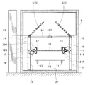
図1〜8に示す実施例1の保存処理装置は、導電性のベルト片1Bが環状に共連接されたベルト構造と、このベルト構造の側部ないし上部を囲うトンネル状空間の庫室4とを有してなるトンネル式のフリーザーである。具体的には、実施例1では、対象物Oを載置する導電性の載置面を有する載置部1と、
載置部1の両側方又は上方の少なくともいずれかに配置され、載置面に載置された対象物Oから見て両側方又は上方の少なくともいずれかを囲う導電性の囲い構造3/5と、
これら第一電極21、第二電極22、第三電極23、及び第四電極24のそれぞれに電気接続された電圧供給部20と、を具備してなる。
そして、各配置箇所を通過移動する上側のベルト片1Bの片端上部または片端下部に接するローラー接点21R,22Rを有し、ベルト構造によって、ベルト片1B上の対象物Oを運搬する間に、電気印加によって運搬空間内に電気エネルギー場を生成する。The storage processing apparatus of Example 1 shown in FIGS. 1 to 8 includes a belt structure in which
A conductive
The
And it has
(電極)
実施例1では、いずれも載置部1に載置された対象物Oから見て、
載置部1の一側部11S寄りの上部位置に接触した第一電極21と、載置部1の他側部12S寄りの下部位置に接触した第二電極22と、囲い構造3/5の一側部寄りの位置に接触した第三電極23と、囲い構造3/5の他側部寄りの位置に接触した第四電極24と、からなる四つの電極を具備する。(electrode)
In Example 1, as viewed from the object O placed on the
The
(電圧の印加)
前記電圧供給部20は、
第一電極21及び第二電極22のいずれか一方及び他方にそれぞれ、300V〜6000Vのマイナスの直流電圧及び、マイナスの直流電圧の電位を超えない電位の交流電圧を同時印加する。またこれと同時に、第三電極23及び第四電極24のいずれか一方及び他方にそれぞれ、300V〜6000Vのマイナスの直流電圧及び、マイナスの直流電圧の電位を超えない電位の交流電圧を同時印加する。(Apply voltage)
The
A negative DC voltage of 300 V to 6000 V and an AC voltage having a potential not exceeding the potential of the negative DC voltage are simultaneously applied to one and the other of the
ここで、実施例1の電圧供給部20は、第三電極23及び第四電極24のいずれか一方及び他方にそれぞれ、第一電極21への印加電圧と同じマイナスの直流電圧、及び、第二電極22への印加電圧と同じ交流電圧を同時印加することとなっている。
Here, the
(載置部1)
実施例1の載置部1は、ベルト状に共連結された多数のベルト片1Bからなるベルト体と、ベルト体の進行方向前後の各内面に接してベルト回転を制御する複数のベルトロールRとを有するベルト構造からなり、そして実施例1の第一電極21及び第二電極22は、前記ベルト構造のベルト進行方向に沿う複数の配置個所に、ベルト体の上側のベルト片1Bの片端上面、片端下面の一方及び他方に接するようにして左右一組ずつ配置される。
ベルト体のベルト片1Bは導電体の薄板からなり、一方の側部11Sの近傍に導電体の側部板11が立設固定され、他方の側部12Sの近傍に導電体の側部板12が立設固定される。このうち、側部板11,12よりも側方外側へ貼り出した端部片が、離間配置された第一、第二電極21,22のそれぞれに接触する。(Place 1)
The mounting
The
(第一、第二電極)
第一電極21は基本的には、側部の組枠材31に連結されて内側に貼り出す基部アーム210と、貫通ピンを介して保持アーム211の内側に枢支され、上方へ回動可能な上部アーム211と、前記と同じ貫通ピンを介して保持アーム211の内側かつ上部アーム211の下側に枢支され、下方へ回動可能な下部アーム212と、から構成される(図5)。上部アーム211と下部アーム212とは基部アーム210への枢支部分を中心として支持されると共にそれぞれ斜め上方、斜め下方に伸長してなり、上部アームと下部アームの間にバネ11Sが繋がれて、アーム同士の開き角度を所定範囲内に自動調節するものとなっている。上部アーム211、下部アーム212の各先端には、自由転動可能なローラー接点21Rが枠支持されており、上下のローラー接点21Rでベルト片1Bの一方の側端部11Sの上下部分を挟み込むようにして接している。上部アーム211、下部アーム212の伸長する棒状の中央部分には、絶縁体21Iが介設されており、また上部アーム211のみに、電圧供給部20から電気的に接続された電極線25が接続されている。(First and second electrodes)
Basically, the
第二電極22は基本的には、側部の組枠材31に連結されて内側に貼り出す基部アーム220と、貫通ピンを介して保持アーム221の内側に枢支され、上方へ回動可能な上部アーム221と、前記と同じ貫通ピンを介して保持アーム221の内側かつ上部アーム221の下側に枢支され、下方へ回動可能な下部アーム222と、から構成される(図6)。上部アーム221と下部アーム222とは基部アーム220への枢支部分を中心として支持されると共にそれぞれ斜め上方、斜め下方に伸長した導電体からなる。上部アームと下部アームの間にはバネ11Sが繋がれて、上部、下部アーム同士の開き角度を所定範囲内に自動調節するものとなっている。上部アーム221、下部アーム222の各先端には、自由転動可能なローラー接点22Rが枠支持されており、上下のローラー接点22Rでベルト片1Bの一方の側端部11Sの上下部分を挟み込むようにして接している。上部アーム221、下部アーム222の伸長する棒状の中央部分には、絶縁体22Iが介設されており、また下部アーム222のみに、電圧供給部20から電気的に接続された電極線25が接続されている。
The
(囲い構造)
また実施例1の囲い構造は、ベルト構造の側方ないし上下方の周囲を囲う組枠材からなるフレーム構造3と、フレーム構造3の上部の組枠材33に開閉可能に取り付けられた蓋板5とを有してなり、
そして実施例1の第三電極23及び第四電極24は、ベルト進行方向に沿う複数の配置個所に、蓋板5の片端上面、片端下面の一方及び他方に接するようにして左右一組ずつ配置される。(Enclosure structure)
Further, the enclosure structure of the first embodiment includes a
Then, the
(フレーム構造3)
フレーム構造3は具体的には、柱状の複数の側部の組枠材31と、側部の組枠材31の下端に固定されて略水平に連なった下部の組枠材32と、側部の組枠材31の上端に固定されて略水平に連なった上部の組枠材33と、から構成され、これらがすべて矩形断面からなる棒状の組枠材によって一体的に枠構成される。
フレーム構造3のうち側部の組枠材31は、ベルトの進行方向に沿う複数個所に離間して立設される。
フレーム構造3のうち下部の組枠材32は、トンネル状空間の底部にて平面方向に四方枠組みされる。
フレーム構造3のうち上部の組枠材33は、各枠材が略水平に拡がって一体的に枠構成され、ベルト構造の上方にて平面方向に四方枠組みされると共に、ベルト進行方向中間及び幅方向中間に中枠材33Cが通されてなる。(Frame structure 3)
Specifically, the
The
The
The
(蓋板5)
蓋板5は左右それぞれに分離した左右一組の開閉蓋からなる。またベルトの進行方向に沿って2組に分かれて設置される。各蓋板5は、上部の組枠材33のうち、ベルトの進行方向と平行な側部枠材上に沿ってヒンジ固定され、中間材33Cの上に載置されて閉状態(S)を維持する一方、側部枠材上に立てることで開状態(O)を維持することもできる。メンテナンス或いは電気エネルギー場調整を目的として、図1に示すように一部の組を開状態(O)とし、残りの組を閉状態(S)とすることで、ベルト体上を運搬される対象物Oの電気エネルギー場による影響の付与時間を変えることができる。(Cover plate 5)
The
蓋板5は板枠の内部に多数の孔5Hが形成された孔空き板からなる。孔は図7a,bのようにワイヤー5Wの網組によって形成されてもよいし、図7c,dのように導電性の金属板を打ち抜き加工して形成してもよい。
The
(庫室4及び温度調節機F)
庫室4は、前後両端に入口及び出口を有して前記ベルト構造、フレーム構造3、及び蓋板5を囲うトンネル状の空間で構成され、温度調節機Fは、ベルト構造上の対象物Oをベルト構造による運搬中に冷却するものである。(
The
図9に示す実施例2の保存処理装置は、庫室4内に冷凍液6Sを保持する冷凍機構付の水槽6と、水槽6内の冷凍液6S中を潜って通る上下挟み込みベルト1UB、1LBと、複数の金属塊からなるインゴット1Iがベルト状に連なり、上部のインゴットが冷凍液6Sに半浸するように構成されたインゴットベルト構造と、を具備して構成される。インゴットベルトの上部には中空蓋5が固定され、中空蓋5の一方の片端の上部と他方の片端の下部にそれぞれ第三、第四電極が接続される。また水槽の一方の片端の上部と他方の片端の下部にそれぞれ第一、第二電極が接続される。中空蓋5は図7c又はdに示すような通気孔5Hが多数形成されたパンチングプレートからなり、その下面全体を通気孔5Hと共に覆って金属系の導電性繊維が貼り付けられる。また中空蓋5の上部には、庫室4の天井部に沿って設けられた温度調節機FたるブリーズF1からの冷風が当たる。この温度調節機FたるブリーズF1からの冷風は、庫室4内及びインゴットベルトの上部の対象物O1を冷却している。
The storage processing apparatus according to the second embodiment shown in FIG. 9 includes a
上記構成により、液耐性のある対象物O2を冷凍液中に通して運搬冷凍する液体冷凍と、液耐性のない対象物O1をインゴットベルトで運搬冷凍するベルト運搬冷凍と、の両方式を有するハイブリッド冷凍機を構成することとなる。 According to the above configuration, a hybrid having both of a liquid refrigeration for transporting and freezing a liquid-resistant object O2 through a frozen liquid and a belt-transporting refrigeration for transporting and freezing an object O1 having no liquid resistance with an ingot belt. A refrigerator will be constituted.
図10に示す実施例3の保存処理装置は、庫室4内に密閉静置された、載置箱10からなる対象物Oの収容箱と、その上部開放口を覆って密閉された蓋枠50とからなる密閉箱状の載置部1兼囲い構造を有してなり、かつ、この密閉箱の内面に沿って、金属系の導電性繊維Sが内貼りされてなる。本実施例の保存処理装置においては、さらに密閉箱の内部に載置する対象物Oを、金属系の導電性繊維Sで包んだものとしてもよい。
The storage processing apparatus according to the third embodiment shown in FIG. 10 includes a container box for the object O composed of the mounting
金属系の導電性繊維Sは具体的には、帯電材である硫化銅を練り込んだ有機繊維を織布化又は不織布化して得られた、表面抵抗80〜100Ω/m2の有機導電性繊維をいい、あえて少量帯電用の半導電性繊維を用いることで、抗菌性を確保しつつ対象物周りでの余分な電気伝導を抑えるものとしている。また本繊維Sはマイナスに帯電しやすいものであり、セット電極のうち一方の電極にてマイナスの直流電圧をかけることで、対象物Oの周囲に若干のプラス帯電性を保持させつづけることができる。この密閉箱は、載置箱の上部に導電性パッキン1Pが貼り付けられており、密閉したときに蓋枠50との間の隙間を埋めると共に、蓋枠と載置箱とが電気的につながるように構成されている。図10(a)〜(d)に示す側壁の各位置に、それぞれ第一、第二電極、第三、第四電極のいずれ一組又は二組が接続される。
Specifically, the metal-based conductive fiber S is an organic conductive fiber having a surface resistance of 80 to 100 Ω / m 2 obtained by woven or non-woven an organic fiber kneaded with copper sulfide as a charging material. Okay, by using semi-conductive fibers for small amounts of charging, it is intended to suppress excess electrical conduction around the object while ensuring antibacterial properties. The fiber S is easily negatively charged. By applying a negative DC voltage to one of the set electrodes, it is possible to keep a slight positive charge around the object O. . In this sealed box, the
図11に示す実施例4の保存処理装置は、上部に張り巡らされた2本の架線23W、24Wにそれぞれ接する受電アーム20Aを有した移動式の庫室電車4C内に、棚板となる載置部1を多数収容した棚枠30を複数個収容してなる。庫室4は下部の車輪4Rによって、架線23W、24Wに沿って受電しながら自走する庫室電車4Cをなす。電車上部の電源供給部20α、20βは、それぞれの架線23W,24Wから受電して交流電位の調整、並びに交流直流変換と電位調整を行い、庫室電車内の壁に配線された導電線23L,24Lを通じて、棚枠側部の2つのコネクタ23C,24Cのそれぞれに電気接続される。また棚枠30はその枠辺に沿ってコネクタ23Cから枠の一側部上部奥側角部の第三電極23に、シリコンカバーされた電線で配線され、コネクタ24Cから枠の他側部下部手前側角部の第四電極24に、シリコンカバーされた電線で配線される。また棚板である載置板1は導電性板であり、棚枠から電位を受ける。
The storage processing apparatus according to the fourth embodiment shown in FIG. 11 is mounted as a shelf board in a
図12、図13に示す実施例5の保存処理装置は、上部に張り巡らされた1本の架線Wにそれぞれ乗車した滑車車輪70Rが自ら動力回転することで自走する自走車輪70R式の吊り滑車構造からなる。滑車車輪は対象物を吊り下げて係止支持する係止フック7Fを備えると共に、係止フック7Fの両側方へ張り出した上下対称の張り出し枠71に付属した接点ローラー74R,75Rによって、両側部の壁からそれぞれマイナス直流電位、交流電位の電圧を受電する。庫室4は図12にて向かって右側に示す入口シート4Cから、向かって左側に示す出口シート4Cにかけて倒立U字状に屈曲した通路からなり、この通路の進行方向に沿って上部に1本の架線Wが張り巡らされ、張り巡らされた架線Wに吊持されて自走車輪70R式の吊り滑車構造が、対象物Oを運搬する。運搬後には冷蔵又は冷凍が完了しているものとなる。個室の両側壁にはローラー枠4Fがそれぞれ、接点ローラー74R,75Rに接する上下位置にて全側方へ張り巡らされ、各接点ローラーはこれに沿って進行することとなる。但し進行方向向かって右上、左下には接点ローラーの代わりに円形断面のガイシ74G、75Gを滑動可能に設けており、向かて右下と左上のみの接点ローラー74R,75Rで受電するものとしている。
The storage processing apparatus of the fifth embodiment shown in FIGS. 12 and 13 is a self-propelled
その他、本発明は上述した実施例に不要に限定されることはなく、本発明の趣旨を逸脱しない範囲で、適宜、電極の配置、囲い構造の構成、形成態様ないし配置を選択し、或いは上記実施例の要素を組み合わせたり、一部抽出したり、部分的に適用したりすることができる。 In addition, the present invention is not unnecessarily limited to the above-described embodiments, and the arrangement of the electrodes, the configuration of the enclosing structure, the form of formation or the arrangement are appropriately selected within the scope not departing from the gist of the present invention, or the above The elements of the embodiment can be combined, partially extracted, or partially applied.
対象物O
載置部1
載置箱10
一側部11S
導電性パッキン1P
第一電極21
他側部12S
第二電極22
第三電極23
第四電極24
電圧供給部20
フレーム構造3
棚枠30
側部フレーム31
庫室4
蓋板5
蓋枠50
温度調節機F
ベルト片1B
ベルトロールR
導電性繊維S
固定フック7FObject O
Mounting
One
Temperature controller F
Belt roll R
Conductive fiber S
Fixed
Claims (5)
対象物を載置または係止する導電性の載置面または係止部を有する載置部と、
載置部の上部に連なって、又は載置部の近傍に離間して構成され、載置面に載置された対象物から見て両側方向、前後方向、又は上下方向の少なくともいずれかを囲う導電性の囲い構造と、
載置部の一側部寄り及び他側部寄りの位置に各々接触した、直流電極と交流電極とからなる第一電極と第二電極のセットで構成される2セット以上の載置部の電極セットと、
囲い構造の一側部寄り及び他側部寄りの位置に各々接触した、直流電極と交流電極とからなる第三電極と第四電極のセットで構成される2セット以上の囲い構造の電極セットと、
載置部の電極セットを構成する各電極それぞれに電気接続され、各電極セットを構成する第一電極と第二電極のうち一方の電極にマイナスの直流電圧を供給すると共に、他方の電極に交流電圧を供給し、かつ、囲い構造の電極セットを構成する各電極それぞれに電気接続され、各電極セットを構成する第三電極と第四電極のうち一方の電極にマイナスの直流電圧を供給すると共に、他方の電極に交流電圧を供給する電圧供給部と、を具備してなり、
前記電極セットを構成する第一電極と第二電極のうち一方及び他方の電極、並びに、第三電極と第四電極のうち一方及び他方の電極は、載置または係止された対象物からみた外方一面の対角線方向の先に離間した対称位置であって載置部及び囲い構造の前後方向の複数個所にそれぞれ配置され、
対象物から見て両側方向、前後方向、又は上方の少なくともいずれかを導電体で囲った状態で、
前記電圧供給部が、対象物の周囲を囲う載置部又は囲い構造のいずれか外方一面にて、対象物を中央寄りとする対角線方向の両方向に離間配置された各電極の一方及び他方にそれぞれ、マイナスの直流電圧及び交流電圧を、前後方向の複数位置から同時印加することを特徴とする保存処理装置。 A storage processing apparatus for processing an object including an oxide into a storable state,
A mounting portion having a conductive mounting surface or a locking portion for mounting or locking an object; and
It is configured to be connected to the upper portion of the mounting portion or spaced apart in the vicinity of the mounting portion, and surrounds at least one of the both-side direction, the front-rear direction, and the vertical direction when viewed from the object mounted on the mounting surface. A conductive enclosure,
Electrodes of two or more sets of mounting parts each composed of a set of a first electrode and a second electrode composed of a DC electrode and an AC electrode, which are in contact with positions near one side and the other side of the mounting part, respectively. Set,
An electrode set having two or more sets of enclosure structures each composed of a set of a third electrode and a fourth electrode composed of a DC electrode and an AC electrode, which are in contact with positions near one side and the other side of the enclosure structure, respectively. ,
It is electrically connected to each electrode that constitutes the electrode set of the mounting portion, and supplies a negative DC voltage to one of the first electrode and the second electrode that constitute each electrode set, and AC to the other electrode While supplying a voltage and being electrically connected to each electrode constituting the electrode set of the enclosed structure, a negative DC voltage is supplied to one of the third electrode and the fourth electrode constituting each electrode set. A voltage supply unit for supplying an AC voltage to the other electrode ,
One and the other electrode of the first electrode and the second electrode constituting the electrode set, and one and the other electrode of the third electrode and the fourth electrode are viewed from the mounted or locked object. It is arranged at a plurality of positions in the front-rear direction of the mounting portion and the surrounding structure at symmetrical positions spaced apart from each other in the diagonal direction on the outer surface,
In a state where at least one of the both sides, the front-rear direction, or the upper side as viewed from the object is surrounded by a conductor,
The voltage supply section is arranged on one and the other of the electrodes that are spaced apart in both directions in the diagonal direction with the object closer to the center on either the outer surface of the mounting part or the surrounding structure that surrounds the object. A storage processing apparatus, wherein negative DC voltage and AC voltage are simultaneously applied from a plurality of positions in the front-rear direction .
電圧供給部によって電気印加された蓋板が、載置面に載置された対象物の上部に電気エネルギー場を形成する請求項1又は2記載の保存処理装置。 The enclosure structure has a lid plate that is disposed at least above the mounting plate and expands in the plane direction and can be separated and opened to the left and right. The upper position near one side of the lid plate and the other side portion The lower part of the side is in contact with the third electrode and the fourth electrode,
The storage processing apparatus according to claim 1 or 2, wherein the lid plate to which electricity is applied by the voltage supply unit forms an electric energy field on an upper part of the object placed on the placement surface.
この導電性繊維が載置部上の対象物を囲った状態で、電圧供給部によってマイナスの直流電圧及び交流電圧を同時印加する請求項1,2、又は3のいずれか記載の保存処理装置。 On the placement surface of the placement unit and the upper part of the enclosure structure, or on both sides and front and rear sides of the enclosure structure, so as to enclose at least one of the vertical direction of the object on the placement unit and the surrounding four sides. Fixed conductive fibers are provided,
4. The storage processing apparatus according to claim 1, wherein a negative DC voltage and an AC voltage are simultaneously applied by a voltage supply unit in a state where the conductive fiber surrounds an object on the mounting unit.
第一電極及び第二電極は、前記ベルト構造のベルト進行方向に沿う複数の配置個所に、ベルト体の上側のベルト片の片端上面、片端下面の一方及び他方に接するようにして左右一組ずつ配置され、
囲い構造は、ベルト構造の側方ないし上下方の周囲を囲う組枠材からなるフレーム構造と、フレーム構造の上部の組枠材に開閉可能に取り付けられた蓋板とを有してなり、
第三電極及び第四電極は、ベルト進行方向に沿う複数の配置個所に、蓋板の片端上面、片端下面の一方及び他方に接するようにして左右一組ずつ配置され、
庫室は、前後両端に入口及び出口を有して前記ベルト構造、フレーム構造、及び蓋板を囲うトンネル状の空間で構成され、
温度調節機は、ベルト構造上の対象物をベルト構造による運搬中に冷却するものである請求項4記載の保存処理装置。
The mounting portion has a belt structure having a belt body composed of a large number of belt pieces that are co-connected in a belt shape, and a plurality of belt rolls that control belt rotation in contact with the inner surfaces of the belt body in the traveling direction. ,
The first electrode and the second electrode are arranged in a plurality of positions along the belt traveling direction of the belt structure, one pair on the left and right sides so as to be in contact with one upper surface and one lower surface of the lower end of the upper end of the belt body. Arranged,
The enclosure structure includes a frame structure made of a frame material that surrounds the side or upper and lower periphery of the belt structure, and a cover plate that is attached to the upper frame material of the frame structure so as to be openable and closable.
The third electrode and the fourth electrode are arranged in a plurality of locations along the belt traveling direction, one set on the left and one on the other side of the upper surface of the cover plate, one of the lower surface of the one end and the other,
The warehouse is composed of a tunnel-like space that has an entrance and an exit at both front and rear ends and surrounds the belt structure, the frame structure, and the cover plate,
5. The storage processing apparatus according to claim 4, wherein the temperature controller cools an object on the belt structure during transportation by the belt structure.
Applications Claiming Priority (3)
| Application Number | Priority Date | Filing Date | Title |
|---|---|---|---|
| JP2012251717 | 2012-11-16 | ||
| JP2012251717 | 2012-11-16 | ||
| PCT/JP2013/080961 WO2014077377A1 (en) | 2012-11-16 | 2013-11-17 | Preservation treatment device for oxide-containing material |
Publications (2)
| Publication Number | Publication Date |
|---|---|
| JPWO2014077377A1 JPWO2014077377A1 (en) | 2017-01-05 |
| JP6406756B2 true JP6406756B2 (en) | 2018-10-17 |
Family
ID=50731286
Family Applications (1)
| Application Number | Title | Priority Date | Filing Date |
|---|---|---|---|
| JP2014547059A Active JP6406756B2 (en) | 2012-11-16 | 2013-11-17 | Storage device for materials containing oxides |
Country Status (9)
| Country | Link |
|---|---|
| US (1) | US10064423B2 (en) |
| EP (1) | EP2921061B1 (en) |
| JP (1) | JP6406756B2 (en) |
| KR (1) | KR102117735B1 (en) |
| CN (1) | CN104994752B (en) |
| AU (1) | AU2013345797B2 (en) |
| ES (1) | ES2649970T3 (en) |
| NO (1) | NO2921061T3 (en) |
| WO (1) | WO2014077377A1 (en) |
Cited By (1)
| Publication number | Priority date | Publication date | Assignee | Title |
|---|---|---|---|---|
| KR20150083460A (en) * | 2012-11-16 | 2015-07-17 | 유겐가이샤 아토무 | Preservation treatment device for oxide-containing material |
Families Citing this family (1)
| Publication number | Priority date | Publication date | Assignee | Title |
|---|---|---|---|---|
| CN104365575B (en) * | 2014-12-10 | 2016-06-22 | 甘肃惠森药业发展有限公司 | Brief shock method stores the method for stem and leaf class Chinese crude drug |
Family Cites Families (21)
| Publication number | Priority date | Publication date | Assignee | Title |
|---|---|---|---|---|
| US3966581A (en) * | 1974-10-16 | 1976-06-29 | Auric Corporation | Selective plating apparatus |
| JPS5915996B2 (en) * | 1980-12-03 | 1984-04-12 | 新日本製鐵株式会社 | Electrolytic treatment equipment in continuous metal plate processing equipment |
| US4457221A (en) * | 1980-12-23 | 1984-07-03 | Geren David K | Sterilization apparatus |
| US4680100A (en) * | 1982-03-16 | 1987-07-14 | American Cyanamid Company | Electrochemical cells and electrodes therefor |
| JPS60217930A (en) * | 1984-04-03 | 1985-10-31 | 株式会社 同和 | Method and device for manufacturing conducting processed food |
| JPH0769105B2 (en) | 1986-06-18 | 1995-07-26 | 松下電器産業株式会社 | Food storage device |
| JPS6356272A (en) * | 1986-08-25 | 1988-03-10 | Dowa:Kk | Vessel for preparation of electrically processed food |
| CN2037053U (en) * | 1988-10-31 | 1989-05-03 | 张书林 | Electronic freshness-keeping refrigerating box |
| WO1990015547A1 (en) * | 1989-06-12 | 1990-12-27 | Foodco Corporation | High pulsed voltage systems for extending the shelf life of pumpable food products |
| CN2094209U (en) * | 1991-04-29 | 1992-01-29 | 汪又鼎 | Electronic fresh-keeping sterilizing cabinet |
| CA2255689C (en) | 1997-03-17 | 2013-07-09 | Akinori Ito | Method and equipment for treating electrostatic field and electrode used therein |
| EP0968661A4 (en) * | 1997-08-14 | 2000-01-05 | Yamamoto Vinita Co Ltd | Packed food pasteurizing device and pasteurizing method |
| US6093432A (en) * | 1998-08-13 | 2000-07-25 | University Of Guelph | Method and apparatus for electrically treating foodstuffs for preservation |
| JP2000100636A (en) * | 1998-09-18 | 2000-04-07 | Impulse Giken:Kk | Power supply and apparatus for processing food material using the same |
| JP3494585B2 (en) * | 1999-03-10 | 2004-02-09 | ジョーベン電機株式会社 | Inspection method of sealed package |
| CA2532000C (en) * | 2003-07-17 | 2012-07-03 | Michelin Recherche Et Technique S.A. | Heavy vehicle |
| US20060233925A1 (en) | 2003-08-11 | 2006-10-19 | Yugengaisha Sun World Kawamura | Food preserving method and its device |
| KR100767046B1 (en) * | 2006-08-11 | 2007-10-17 | 삼성전자주식회사 | Preserving apparatus having multiple surface |
| JP6095149B2 (en) * | 2009-04-12 | 2017-03-15 | 有限会社 サンワールド川村 | How to store food |
| EP2717805B1 (en) | 2011-06-09 | 2018-06-20 | Synthes GmbH | Anodizing container |
| ES2649970T3 (en) | 2012-11-16 | 2018-01-16 | Atom Co., Ltd. | Conservation treatment apparatus for oxide containing material |
-
2013
- 2013-11-17 ES ES13855090.0T patent/ES2649970T3/en active Active
- 2013-11-17 EP EP13855090.0A patent/EP2921061B1/en not_active Not-in-force
- 2013-11-17 KR KR1020157015303A patent/KR102117735B1/en active IP Right Grant
- 2013-11-17 JP JP2014547059A patent/JP6406756B2/en active Active
- 2013-11-17 AU AU2013345797A patent/AU2013345797B2/en not_active Ceased
- 2013-11-17 CN CN201380066288.6A patent/CN104994752B/en active Active
- 2013-11-17 NO NO13855090A patent/NO2921061T3/no unknown
- 2013-11-17 WO PCT/JP2013/080961 patent/WO2014077377A1/en active Application Filing
- 2013-11-17 US US14/443,258 patent/US10064423B2/en not_active Expired - Fee Related
Cited By (2)
| Publication number | Priority date | Publication date | Assignee | Title |
|---|---|---|---|---|
| KR20150083460A (en) * | 2012-11-16 | 2015-07-17 | 유겐가이샤 아토무 | Preservation treatment device for oxide-containing material |
| KR102117735B1 (en) | 2012-11-16 | 2020-06-01 | 유겐가이샤 아토무 | Preservation treatment device for oxide-containing material |
Also Published As
| Publication number | Publication date |
|---|---|
| EP2921061A1 (en) | 2015-09-23 |
| AU2013345797B2 (en) | 2017-07-20 |
| KR20150083460A (en) | 2015-07-17 |
| WO2014077377A1 (en) | 2014-05-22 |
| EP2921061B1 (en) | 2017-11-15 |
| US20150351446A1 (en) | 2015-12-10 |
| US10064423B2 (en) | 2018-09-04 |
| CN104994752B (en) | 2017-07-18 |
| NO2921061T3 (en) | 2018-04-14 |
| CN104994752A (en) | 2015-10-21 |
| KR102117735B1 (en) | 2020-06-01 |
| AU2013345797A1 (en) | 2015-07-02 |
| ES2649970T3 (en) | 2018-01-16 |
| EP2921061A4 (en) | 2016-04-27 |
| JPWO2014077377A1 (en) | 2017-01-05 |
Similar Documents
| Publication | Publication Date | Title |
|---|---|---|
| US10582717B2 (en) | Storage device | |
| JP6406756B2 (en) | Storage device for materials containing oxides | |
| JP5593235B2 (en) | Electric field processing refrigerated storage | |
| WO2014042271A1 (en) | Electric-field treatment device and electric-field treatment method | |
| WO2015040816A1 (en) | Thawing method for frozen goods | |
| TWI652994B (en) | Storage processing device containing material of oxide | |
| JP5288286B2 (en) | Food thawing / refrigerated storage equipment | |
| CN110720579A (en) | Food fresh-keeping system | |
| JP6095149B2 (en) | How to store food | |
| JP2008267750A (en) | Treatment apparatus | |
| EP3494799A1 (en) | Thawing machine | |
| CN206284309U (en) | A kind of food preservative technology equipment | |
| JP2007111011A (en) | Food storage facility and food storage method | |
| CN217074166U (en) | Dynamic electric field frame type multi-temperature-bin fresh-keeping carriage | |
| JP3161800U (en) | Substance freshness maintenance equipment | |
| WO2015060336A1 (en) | Refrigeration facility, method for manufacturing refrigerated food and drink products, and humidifier for refrigeration facility | |
| JP2023041285A (en) | Storage warehouse | |
| JP2018027064A (en) | Thawing device | |
| NZ721355B2 (en) | Space potential generation device, a storage device for maintaining a freshness of an object stored therein using such space potential generation device, and fryer provided with such space potential generation device |
Legal Events
| Date | Code | Title | Description |
|---|---|---|---|
| A621 | Written request for application examination |
Free format text: JAPANESE INTERMEDIATE CODE: A621 Effective date: 20161116 |
|
| A131 | Notification of reasons for refusal |
Free format text: JAPANESE INTERMEDIATE CODE: A131 Effective date: 20171031 |
|
| A603 | Late request for extension of time limit during examination |
Free format text: JAPANESE INTERMEDIATE CODE: A603 Effective date: 20180202 |
|
| A521 | Request for written amendment filed |
Free format text: JAPANESE INTERMEDIATE CODE: A523 Effective date: 20180228 |
|
| TRDD | Decision of grant or rejection written | ||
| A01 | Written decision to grant a patent or to grant a registration (utility model) |
Free format text: JAPANESE INTERMEDIATE CODE: A01 Effective date: 20180704 |
|
| R155 | Notification before disposition of declining of application |
Free format text: JAPANESE INTERMEDIATE CODE: R155 |
|
| A61 | First payment of annual fees (during grant procedure) |
Free format text: JAPANESE INTERMEDIATE CODE: A61 Effective date: 20180914 |
|
| R150 | Certificate of patent or registration of utility model |
Ref document number: 6406756 Country of ref document: JP Free format text: JAPANESE INTERMEDIATE CODE: R150 |
|
| R250 | Receipt of annual fees |
Free format text: JAPANESE INTERMEDIATE CODE: R250 |
|
| S111 | Request for change of ownership or part of ownership |
Free format text: JAPANESE INTERMEDIATE CODE: R313113 |
|
| R360 | Written notification for declining of transfer of rights |
Free format text: JAPANESE INTERMEDIATE CODE: R360 |
|
| R360 | Written notification for declining of transfer of rights |
Free format text: JAPANESE INTERMEDIATE CODE: R360 |
|
| R371 | Transfer withdrawn |
Free format text: JAPANESE INTERMEDIATE CODE: R371 |
|
| R250 | Receipt of annual fees |
Free format text: JAPANESE INTERMEDIATE CODE: R250 |
|
| S111 | Request for change of ownership or part of ownership |
Free format text: JAPANESE INTERMEDIATE CODE: R313113 |
|
| S531 | Written request for registration of change of domicile |
Free format text: JAPANESE INTERMEDIATE CODE: R313531 |
|
| R350 | Written notification of registration of transfer |
Free format text: JAPANESE INTERMEDIATE CODE: R350 |
|
| R250 | Receipt of annual fees |
Free format text: JAPANESE INTERMEDIATE CODE: R250 |