JP6395471B2 - Liquid storage container and liquid discharge device - Google Patents

Liquid storage container and liquid discharge device Download PDF

Info

Publication number
JP6395471B2
JP6395471B2 JP2014132854A JP2014132854A JP6395471B2 JP 6395471 B2 JP6395471 B2 JP 6395471B2 JP 2014132854 A JP2014132854 A JP 2014132854A JP 2014132854 A JP2014132854 A JP 2014132854A JP 6395471 B2 JP6395471 B2 JP 6395471B2
Authority
JP
Japan
Prior art keywords
ink
storage chamber
liquid
liquid storage
negative pressure
Prior art date
Legal status (The legal status is an assumption and is not a legal conclusion. Google has not performed a legal analysis and makes no representation as to the accuracy of the status listed.)
Active
Application number
JP2014132854A
Other languages
Japanese (ja)
Other versions
JP2016010887A (en
JP2016010887A5 (en
Inventor
浩志 越川
浩志 越川
小瀧 靖夫
小瀧  靖夫
宇田川 健太
健太 宇田川
直純 鍋島
直純 鍋島
壮至 近藤
壮至 近藤
政文 関
政文 関
Current Assignee (The listed assignees may be inaccurate. Google has not performed a legal analysis and makes no representation or warranty as to the accuracy of the list.)
Canon Inc
Original Assignee
Canon Inc
Priority date (The priority date is an assumption and is not a legal conclusion. Google has not performed a legal analysis and makes no representation as to the accuracy of the date listed.)
Filing date
Publication date
Application filed by Canon Inc filed Critical Canon Inc
Priority to JP2014132854A priority Critical patent/JP6395471B2/en
Priority to US14/744,926 priority patent/US9333758B2/en
Publication of JP2016010887A publication Critical patent/JP2016010887A/en
Publication of JP2016010887A5 publication Critical patent/JP2016010887A5/ja
Application granted granted Critical
Publication of JP6395471B2 publication Critical patent/JP6395471B2/en
Active legal-status Critical Current
Anticipated expiration legal-status Critical

Links

Images

Classifications

    • BPERFORMING OPERATIONS; TRANSPORTING
    • B41PRINTING; LINING MACHINES; TYPEWRITERS; STAMPS
    • B41JTYPEWRITERS; SELECTIVE PRINTING MECHANISMS, i.e. MECHANISMS PRINTING OTHERWISE THAN FROM A FORME; CORRECTION OF TYPOGRAPHICAL ERRORS
    • B41J2/00Typewriters or selective printing mechanisms characterised by the printing or marking process for which they are designed
    • B41J2/005Typewriters or selective printing mechanisms characterised by the printing or marking process for which they are designed characterised by bringing liquid or particles selectively into contact with a printing material
    • B41J2/01Ink jet
    • B41J2/17Ink jet characterised by ink handling
    • B41J2/175Ink supply systems ; Circuit parts therefor
    • B41J2/17503Ink cartridges
    • B41J2/1752Mounting within the printer
    • B41J2/17523Ink connection
    • BPERFORMING OPERATIONS; TRANSPORTING
    • B41PRINTING; LINING MACHINES; TYPEWRITERS; STAMPS
    • B41JTYPEWRITERS; SELECTIVE PRINTING MECHANISMS, i.e. MECHANISMS PRINTING OTHERWISE THAN FROM A FORME; CORRECTION OF TYPOGRAPHICAL ERRORS
    • B41J2/00Typewriters or selective printing mechanisms characterised by the printing or marking process for which they are designed
    • B41J2/005Typewriters or selective printing mechanisms characterised by the printing or marking process for which they are designed characterised by bringing liquid or particles selectively into contact with a printing material
    • B41J2/01Ink jet
    • B41J2/17Ink jet characterised by ink handling
    • B41J2/175Ink supply systems ; Circuit parts therefor
    • B41J2/17503Ink cartridges
    • B41J2/17513Inner structure
    • BPERFORMING OPERATIONS; TRANSPORTING
    • B41PRINTING; LINING MACHINES; TYPEWRITERS; STAMPS
    • B41JTYPEWRITERS; SELECTIVE PRINTING MECHANISMS, i.e. MECHANISMS PRINTING OTHERWISE THAN FROM A FORME; CORRECTION OF TYPOGRAPHICAL ERRORS
    • B41J2/00Typewriters or selective printing mechanisms characterised by the printing or marking process for which they are designed
    • B41J2/005Typewriters or selective printing mechanisms characterised by the printing or marking process for which they are designed characterised by bringing liquid or particles selectively into contact with a printing material
    • B41J2/01Ink jet
    • B41J2/17Ink jet characterised by ink handling
    • B41J2/175Ink supply systems ; Circuit parts therefor
    • B41J2/17503Ink cartridges
    • B41J2/1752Mounting within the printer
    • BPERFORMING OPERATIONS; TRANSPORTING
    • B41PRINTING; LINING MACHINES; TYPEWRITERS; STAMPS
    • B41JTYPEWRITERS; SELECTIVE PRINTING MECHANISMS, i.e. MECHANISMS PRINTING OTHERWISE THAN FROM A FORME; CORRECTION OF TYPOGRAPHICAL ERRORS
    • B41J2/00Typewriters or selective printing mechanisms characterised by the printing or marking process for which they are designed
    • B41J2/005Typewriters or selective printing mechanisms characterised by the printing or marking process for which they are designed characterised by bringing liquid or particles selectively into contact with a printing material
    • B41J2/01Ink jet
    • B41J2/17Ink jet characterised by ink handling
    • B41J2/175Ink supply systems ; Circuit parts therefor
    • B41J2/17503Ink cartridges
    • B41J2/17553Outer structure
    • BPERFORMING OPERATIONS; TRANSPORTING
    • B41PRINTING; LINING MACHINES; TYPEWRITERS; STAMPS
    • B41JTYPEWRITERS; SELECTIVE PRINTING MECHANISMS, i.e. MECHANISMS PRINTING OTHERWISE THAN FROM A FORME; CORRECTION OF TYPOGRAPHICAL ERRORS
    • B41J2/00Typewriters or selective printing mechanisms characterised by the printing or marking process for which they are designed
    • B41J2/005Typewriters or selective printing mechanisms characterised by the printing or marking process for which they are designed characterised by bringing liquid or particles selectively into contact with a printing material
    • B41J2/01Ink jet
    • B41J2/17Ink jet characterised by ink handling
    • B41J2/175Ink supply systems ; Circuit parts therefor
    • B41J2/17503Ink cartridges
    • B41J2/17556Means for regulating the pressure in the cartridge

Landscapes

  • Ink Jet (AREA)

Description

本発明は、液体収納室内に液体を収納する液体収納容器及びその液体収納容器を搭載する液体吐出装置に関し、特に、液体収納室の内部の負圧が所定の負圧を超えたときに液体収納室の内部に空気を充填する液体収納容器及び液体吐出装置に関するものである。   The present invention relates to a liquid storage container for storing a liquid in a liquid storage chamber and a liquid discharge apparatus equipped with the liquid storage container, and in particular, the liquid storage when the negative pressure inside the liquid storage chamber exceeds a predetermined negative pressure. The present invention relates to a liquid storage container and a liquid discharge device for filling the inside of a chamber with air.

インクジェット記録装置においては、キャリッジにインク収納容器を搭載し、インク収納容器の内部に収納されたインクを記録ヘッドに供給する形式のものがある。インク収納容器としては、記録ヘッドに供給されたインクが吐出口から漏れることのないように、インク収納容器の内部に負圧が形成されるものがある。   Some inkjet recording apparatuses have an ink storage container mounted on a carriage and supply ink stored in the ink storage container to a recording head. Some ink storage containers have a negative pressure formed inside the ink storage container so that the ink supplied to the recording head does not leak from the ejection port.

内部に負圧の形成されるインク収納容器として、例えば、内部に可撓性のフィルムによって形成された袋状部材が配置され、袋状部材の内部または外部には、袋状部材が容積を拡張する方向にフィルムを付勢するばね等が取り付けられているものがある。このような構成によって袋状部材の内部が負圧に保たれているインク収納容器では、内部のインクが消費されていくにつれ、袋状部材の内部の負圧の絶対値が徐々に大きくなっていく。   For example, a bag-like member formed of a flexible film is disposed inside the ink storage container in which negative pressure is formed, and the bag-like member expands the volume inside or outside the bag-like member. Some have springs or the like that bias the film in the direction of the movement. In the ink storage container in which the inside of the bag-like member is maintained at a negative pressure by such a configuration, the absolute value of the negative pressure inside the bag-like member gradually increases as the internal ink is consumed. Go.

負圧は−値表現、毛細管力は+値で表現することが一般的であるが、両者の力の釣り合いを分かり易く表現するために、本明細書では値の正負を区別せずに「絶対値」という表現を用いている。   In general, negative pressure is expressed as a negative value, and capillary force is expressed as a positive value. However, in order to express the balance of both forces in an easy-to-understand manner, this specification does not distinguish between positive and negative values. The expression “value” is used.

インク収納容器における袋状部材の内部の負圧を一定に保つために、内部の負圧の大きさが一定の値を超えたときに空気が袋状部材の内部に供給されることを許容するフィルタが取り付けられたインク収納容器について特許文献1及び特許文献2に開示されている。袋状部材内部の負圧が一定の大きさを超えたときに、フィルタを介して外部から袋状部材の内部に空気が導入されるので、袋状部材内部の負圧が過度に大きくならず、袋状部材内部の負圧が一定に保たれる。   In order to keep the negative pressure inside the bag-like member in the ink storage container constant, air is allowed to be supplied to the inside of the bag-like member when the magnitude of the internal negative pressure exceeds a certain value. Patent Document 1 and Patent Document 2 disclose an ink storage container to which a filter is attached. When the negative pressure inside the bag-like member exceeds a certain level, air is introduced from the outside into the bag-like member through the filter, so the negative pressure inside the bag-like member does not become excessively large. The negative pressure inside the bag-like member is kept constant.

特開2011−206936号公報JP 2011-206936 A 米国特許7703903号明細書US Pat. No. 7,703,903

袋状部材の内部の負圧の大きさが一定の値を超えたときに空気が袋状部材の内部に供給されることを許容するフィルタは、液体によって浸されていることが求められる。   A filter that allows air to be supplied to the inside of the bag-like member when the magnitude of the negative pressure inside the bag-like member exceeds a certain value is required to be immersed in the liquid.

しかしながら、特許文献1及び特許文献2に開示されているインク収納容器では、フィルタの周囲に液体が存在しないような場合もあり得る。そのような状態でインク収納容器が配置された場合、フィルタの内部に空気が残留する可能性がある。   However, in the ink storage containers disclosed in Patent Document 1 and Patent Document 2, there may be a case where no liquid exists around the filter. When the ink storage container is disposed in such a state, air may remain inside the filter.

フィルタの内部に空気が存在する場合には、メニスカスがフィルタ内部で保たれず、インク収納容器の外部の空気がインク収納容器の内部に入り込む可能性がある。これによって、インク収納容器内部で負圧が保たれず、記録ヘッドあるいはインク収納容器の内部にインクを保持しきれなくなる可能性がある。   When air is present inside the filter, the meniscus is not kept inside the filter, and air outside the ink container may enter the ink container. As a result, the negative pressure is not maintained inside the ink storage container, and there is a possibility that the ink cannot be held inside the recording head or the ink storage container.

そこで、本発明は上記の事情に鑑み、より確実に内部の負圧を保つことのできる液体収納容器を提供することを目的とする。   Therefore, in view of the above circumstances, an object of the present invention is to provide a liquid storage container that can more reliably maintain an internal negative pressure.

本発明の液体収納容器は、液体を収納する液体収納室と、前記液体収納室に形成され、外部と前記液体収納室とが連通する連通部と、前記液体収納室の内部で負圧を形成する負圧形成手段と、前記連通部に取り付けられ、前記液体収納室の内部の負圧に応じて、外部から前記液体収納室の内部への空気の通過を許容し、前記連通部と当接する規制部材と、前記液体収納室における液体の貯留された部分から前記規制部材に液体を供給し、前記液体収納室の内部で前記規制部材と当接する液体供給手段とを有し、前記液体供給手段は、毛細管力によって液体を前記規制部材に供給する複数の溝であり、前記複数の溝は、それぞれ異なる方向に延びる溝を含むことを特徴とする。 The liquid storage container of the present invention forms a negative pressure within the liquid storage chamber, a liquid storage chamber for storing the liquid, a communication portion formed in the liquid storage chamber and communicating with the outside and the liquid storage chamber. A negative pressure forming means that attaches to the communication portion, and allows air to pass from the outside to the inside of the liquid storage chamber in accordance with the negative pressure inside the liquid storage chamber and contacts the communication portion a regulating member, the liquid is supplied from the reservoir portion of the liquid to the regulating member in the liquid accommodating chamber, have a said regulating member abutting against the liquid supply means within said liquid receiving chamber, said liquid supply means Is a plurality of grooves for supplying liquid to the regulating member by capillary force, and the plurality of grooves include grooves extending in different directions .

本発明は、より確実に内部の負圧を維持することができるので、液体収納容器からの液体の漏れが生じることが抑えられ、液体収納容器の信頼性を向上させることができる。   According to the present invention, the internal negative pressure can be more reliably maintained, so that leakage of the liquid from the liquid storage container is suppressed, and the reliability of the liquid storage container can be improved.

本発明の第1実施形態に係るインクカートリッジの搭載されるインクジェット記録装置についての概略構成を示した模式的な断面図である。1 is a schematic cross-sectional view showing a schematic configuration of an ink jet recording apparatus on which an ink cartridge according to a first embodiment of the present invention is mounted. 図1のインクジェット記録装置に搭載されるインクカートリッジについての斜視図である。It is a perspective view about the ink cartridge mounted in the inkjet recording device of FIG. 図2のインクカートリッジについて、分解して示した斜視図である。FIG. 3 is an exploded perspective view of the ink cartridge of FIG. 2. 図2のインクカートリッジの断面図である。FIG. 3 is a cross-sectional view of the ink cartridge of FIG. 2. (a)は図2のインクカートリッジがジョイントユニットに搭載される際のインクカートリッジについて示した断面図であり、(b)は搭載が完了した状態のインクカートリッジについて示した断面図である。2A is a cross-sectional view showing the ink cartridge when the ink cartridge of FIG. 2 is mounted on the joint unit, and FIG. 3B is a cross-sectional view showing the ink cartridge in a state where the mounting is completed. (a)は図2のインクカートリッジにおいてインクが十分に充填されている状態について示した断面図であり、(b)は図2のインクカートリッジにおいてインクが消費された状態について示した断面図である。FIG. 3A is a cross-sectional view showing a state where ink is sufficiently filled in the ink cartridge of FIG. 2, and FIG. 3B is a cross-sectional view showing a state where ink is consumed in the ink cartridge of FIG. . (a)は図2のインクカートリッジのフィルタにについて示した断面図であり、(b)はフィルタを介して空気が充填されている状態について示した断面図であり、(c)は空気の充填後にメニスカスが復帰した状態について示した断面図である。(A) is sectional drawing shown about the filter of the ink cartridge of FIG. 2, (b) is sectional drawing shown about the state with which air was filled through the filter, (c) is filling with air It is sectional drawing shown about the state which the meniscus reset later. (a)は図2のインクカートリッジにおける最後に残ったインクと毛管溝との間の関係について説明するための説明図であり、(b)、(c)、(d)は姿勢を変えたときのそれぞれの姿勢で最後に残ったインクと毛管溝とについて示した断面図である。(A) is explanatory drawing for demonstrating the relationship between the ink which remained at the end in the ink cartridge of FIG. 2, and a capillary groove, (b), (c), (d) is when an attitude | position is changed. It is sectional drawing shown about the ink and the capillary groove which remain | survived last in each attitude | position. (a)は本発明の第2実施形態に係るインクカートリッジにおいてインクが十分に充填されている状態について示した断面図であり、(b)はインクが消費された状態について示した断面図であり、(c)は吸収体周辺について示した断面図である。(A) is sectional drawing shown about the state with which ink was fully filled in the ink cartridge which concerns on 2nd Embodiment of this invention, (b) is sectional drawing shown about the state by which the ink was consumed. (C) is sectional drawing shown about the absorber periphery.

以下、本発明に係るインクカートリッジの実施形態について図面を参照しながら具体的に説明する。なお、以下の各実施形態は、本発明を実施するための好適な一例であり、本発明はこれらの構成に限定されるものではない。   Hereinafter, an embodiment of an ink cartridge according to the present invention will be specifically described with reference to the drawings. Each of the following embodiments is a preferred example for carrying out the present invention, and the present invention is not limited to these configurations.

(第1実施形態)
(インクジェット記録装置の構成)
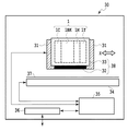
図1に、本発明の第1実施形態に係るインクカートリッジ1の搭載されるインクジェット記録装置(液体吐出装置)の概略構成を示した模式的な断面図を示す。
(First embodiment)
(Configuration of inkjet recording apparatus)
FIG. 1 is a schematic cross-sectional view showing a schematic configuration of an ink jet recording apparatus (liquid ejection apparatus) on which the ink cartridge 1 according to the first embodiment of the present invention is mounted.

記録装置本体30は、キャリッジ31、記録ヘッド32、装着部33、搬送手段34、制御部35を備えている。また、これらの他に、記録装置本体30は、入出力部36、不図示の開閉可能な外装カバー、給装手段、給送カセット、排出トレイおよび操作部などを備えている。インク収納容器(液体収納容器)としてのインクカートリッジ1は、インクジェット記録装置本体(以下、「装置本体」ともいう)30におけるキャリッジ31に搭載されている。また、記録装置本体30は、入出力部36を介して、コンピュータやデジタルカメラ、メモリカードなどの外部装置(不図示)と接続可能なように構成されている。   The recording apparatus main body 30 includes a carriage 31, a recording head 32, a mounting unit 33, a transport unit 34, and a control unit 35. In addition to these, the recording apparatus main body 30 includes an input / output unit 36, an openable / closable exterior cover (not shown), a supply unit, a feeding cassette, a discharge tray, an operation unit, and the like. An ink cartridge 1 as an ink storage container (liquid storage container) is mounted on a carriage 31 in an ink jet recording apparatus main body (hereinafter also referred to as “apparatus main body”) 30. The recording apparatus main body 30 is configured to be connectable to an external device (not shown) such as a computer, a digital camera, or a memory card via the input / output unit 36.

制御部35は、記録装置本体30全体の制御、インクカートリッジ1との情報通信の制御、入出力部36を介して外部装置から入力される情報の解析・処理、および、入出力部36への情報の出力などを実行する。例えば、制御部35は、キャリッジ31、記録ヘッド32、搬送手段34、給装手段などの各デバイスを動作させる命令を発し、各デバイスの動作を制御する。また、制御部35は、インクカートリッジ1に設けられた記憶素子からインク色や初期インク充填量、インク消費量などのカートリッジ固有情報を読み出す制御や、インクカートリッジ1に設けられた記憶素子にインク消費量などの情報を書き込む制御も実行できる。さらには、制御部35は、外部装置から入出力部36を介して入力されるプリント指令や画像データなどの情報を解析・処理し、また、インク残量などの情報を入出力部36に出力することもできる。   The control unit 35 controls the entire recording apparatus main body 30, controls information communication with the ink cartridge 1, analyzes / processes information input from an external device via the input / output unit 36, and sends information to the input / output unit 36. Execute information output. For example, the control unit 35 issues a command to operate each device such as the carriage 31, the recording head 32, the transport unit 34, and the supply unit, and controls the operation of each device. The control unit 35 controls the reading of cartridge specific information such as the ink color, initial ink filling amount, and ink consumption from the storage element provided in the ink cartridge 1, Control to write information such as quantity can also be executed. Further, the control unit 35 analyzes and processes information such as a print command and image data input from an external device via the input / output unit 36, and outputs information such as ink remaining amount to the input / output unit 36. You can also

キャリッジ31には、記録ヘッド32及びインクカートリッジ1が取り外し可能に装着可能な装着部(以下、「カートリッジ装着部」あるいは「ホルダ」ともいう)33が設けられている。本実施形態では、記録ヘッド32と装着部33とが一体化されたヘッドユニット(「カートリッジ装着ユニット」ともいう)38が、キャリッジ31に対して取り外し可能に搭載される構造となっている。このキャリッジ31は、記録媒体37の搬送方向と交差するX軸方向に沿って移動可能に構成されている。   The carriage 31 is provided with a mounting portion (hereinafter also referred to as “cartridge mounting portion” or “holder”) 33 to which the recording head 32 and the ink cartridge 1 can be detachably mounted. In the present embodiment, a head unit (also referred to as “cartridge mounting unit”) 38 in which the recording head 32 and the mounting portion 33 are integrated is detachably mounted on the carriage 31. The carriage 31 is configured to be movable along the X-axis direction that intersects the conveyance direction of the recording medium 37.

キャリッジ31に設けられた装着部33は、シアン(C)、ブラック(Bk)、マゼンタ(M)およびイエロー(Y)のインク(液体)をそれぞれ収納するインクカートリッジ1C、1Bk、1M、1Yが取り外し可能に装着されるように構成されている。インクカートリッジ1Bkは、他の3つのインクカートリッジ1C、1M、1Yよりも幅広で大容量に構成されている。また、記録ヘッド32は、シアン(C)、ブラック(Bk)、マゼンタ(M)およびイエロー(Y)のインクをそれぞれ吐出するための各色ヘッド部を備えており、インクカートリッジ1から供給されるインクが吐出可能なように構成されている。   A mounting portion 33 provided on the carriage 31 removes ink cartridges 1C, 1Bk, 1M, and 1Y that store cyan (C), black (Bk), magenta (M), and yellow (Y) ink (liquid), respectively. It is configured to be mounted as possible. The ink cartridge 1Bk is wider and has a larger capacity than the other three ink cartridges 1C, 1M, and 1Y. Further, the recording head 32 includes color head portions for ejecting cyan (C), black (Bk), magenta (M), and yellow (Y) ink, respectively, and ink supplied from the ink cartridge 1. Is configured to be discharged.

記録ヘッド32には、複数の吐出口が形成されている。記録ヘッド32内における吐出口に延びる流路のそれぞれには、発熱素子が配置されている。発熱素子に通電させ、その発熱素子から熱エネルギーを発生させることにより、流路内のインクが加熱されて膜沸騰により発泡し、そのときの発泡エネルギーによって吐出口からインク滴が吐出される。なお、本実施形態の記録ヘッド32は発熱素子により膜沸騰を発生させて発泡させインク滴を吐出する方式としたが、本発明はこれに限定されない。圧電素子を変形させ、これによって記録ヘッド内部の液体を吐出する形式の記録ヘッドが記録装置に適用されても良く、また、他の形式の記録ヘッドが本発明に適用されても良い。   A plurality of ejection openings are formed in the recording head 32. A heating element is disposed in each of the flow paths extending to the ejection ports in the recording head 32. By energizing the heating element and generating thermal energy from the heating element, the ink in the flow path is heated and foamed by film boiling, and ink droplets are ejected from the ejection port by the foaming energy at that time. Although the recording head 32 of the present embodiment employs a system in which film boiling is generated by a heating element and foamed to eject ink droplets, the present invention is not limited to this. A recording head of a type that deforms the piezoelectric element and thereby discharges liquid inside the recording head may be applied to the recording apparatus, and another type of recording head may be applied to the present invention.

このようなキャリッジ31に対して使用者がインクカートリッジ1の着脱や交換を行う場合には、まず、使用者が、キャリッジ31や搬送手段34などを覆っている外装カバー(不図示)を開状態にする。外装カバーの開状態が記録装置本体によって検出されると、キャリッジ31が「カートリッジ交換位置(不図示)」へ移動する。使用者は、カートリッジ交換位置にあるキャリッジ31にインクカートリッジ1を挿入することができ、また、カートリッジ交換位置にあるキャリッジ31からインクカートリッジ1を取り出すことができる。   When the user attaches / detaches or replaces the ink cartridge 1 to / from such a carriage 31, first, the user opens an exterior cover (not shown) that covers the carriage 31, the conveying means 34, and the like. To. When the open state of the outer cover is detected by the recording apparatus main body, the carriage 31 moves to a “cartridge replacement position (not shown)”. The user can insert the ink cartridge 1 into the carriage 31 at the cartridge replacement position, and can take out the ink cartridge 1 from the carriage 31 at the cartridge replacement position.

インクカートリッジ1の着脱や交換が行われた後、使用者が外装カバーを閉状態にすると、外装カバーの閉状態が検出される。閉状態が検出されると、記録装置本体30の制御部35は、キャリッジ31に装着されているインクカートリッジの記憶素子からインク色情報を読み出す。制御部35は、読み出したインク色情報に基づいて、キャリッジ31に装着されるべき全ての色(本例では4色)のインクカートリッジが揃っているかどうかを判定する。キャリッジ31に装着されていない色のインクカートリッジが存在すると判定された場合、制御部35は、操作部の表示パネルや外部装置の表示部にエラーメッセージを表示させるために、操作部や外部装置に対してエラー表示指令を出す。一方、キャリッジ31に装着されるべき全ての色のインクカートリッジが揃っていると判定された場合、インクジェット記録装置はプリント可能状態となる。   When the user closes the exterior cover after the ink cartridge 1 is attached or detached or replaced, the closed state of the exterior cover is detected. When the closed state is detected, the control unit 35 of the recording apparatus main body 30 reads the ink color information from the storage element of the ink cartridge attached to the carriage 31. Based on the read ink color information, the control unit 35 determines whether all the ink cartridges (four colors in this example) to be mounted on the carriage 31 are prepared. When it is determined that there is an ink cartridge of a color not mounted on the carriage 31, the control unit 35 causes the operation unit or the external device to display an error message on the display panel of the operation unit or the display unit of the external device. In response, an error display command is issued. On the other hand, if it is determined that all the color ink cartridges to be mounted on the carriage 31 are available, the ink jet recording apparatus is ready for printing.

外部装置あるいは操作部から制御部35に記録指令が入力されると、制御部35は、記録装置が記録可能状態になっているかどうかを判定する。記録可能状態になっている場合には、給装手段(不図示)が、給送カセット(不図示)に積載された記録媒体37をピックアップし、ピックアップした記録媒体37を搬送手段34に向けて給装する。搬送手段34は、記録媒体37の下面を支持するプラテン、および、記録媒体37を間欠搬送可能な搬送ローラ、搬送ローラを回転駆動する駆動手段などを備えている。搬送手段34は、給装手段より給装された記録媒体37を、排出トレイ(不図示)へ向けて搬送する。記録媒体37の搬送と搬送の間に、キャリッジ31は、記録媒体37の搬送方向と交差するX方向に沿って移動する。キャリッジ31の移動に伴い、記録ヘッド32から記録媒体37に向けてインクが吐出され、これにより、記録媒体37上に画像が形成される。以上のように、キャリッジ31の移動と記録媒体37の搬送との繰り返しにより、記録媒体37上に画像が形成されていく。   When a recording command is input from the external device or the operation unit to the control unit 35, the control unit 35 determines whether or not the recording device is in a recordable state. When the recording is possible, the supply means (not shown) picks up the recording medium 37 loaded in the feeding cassette (not shown) and directs the picked-up recording medium 37 toward the conveying means 34. To wear. The conveying unit 34 includes a platen that supports the lower surface of the recording medium 37, a conveying roller that can intermittently convey the recording medium 37, and a driving unit that rotationally drives the conveying roller. The transport unit 34 transports the recording medium 37 supplied from the supply unit toward a discharge tray (not shown). During conveyance of the recording medium 37, the carriage 31 moves along the X direction that intersects the conveyance direction of the recording medium 37. As the carriage 31 moves, ink is ejected from the recording head 32 toward the recording medium 37, thereby forming an image on the recording medium 37. As described above, an image is formed on the recording medium 37 by repeating the movement of the carriage 31 and the conveyance of the recording medium 37.

なお、本実施形態では、ヘッドユニット(カートリッジ装着ユニット)38がキャリッジ31に対して取り外し可能に搭載される構造を採用しているが、これに限られるものではない。記録ヘッド32と装着部33とが個別にキャリッジ31に取り外し可能に搭載される形態でもあってよい。また、装着部33がキャリッジ31と一体化されており、記録ヘッド32だけがキャリッジ31に取り外し可能に搭載される形態であってもよい。さらには、記録ヘッド32と装着部33の両方がキャリッジ31に一体化されている形態であってもよい。要するに、キャリッジ31は、記録ヘッド32を搭載可能で、且つ、インクカートリッジ1が着脱可能なように構成されていればよい。   In the present embodiment, a structure in which the head unit (cartridge mounting unit) 38 is detachably mounted on the carriage 31 is employed, but the present invention is not limited to this. The recording head 32 and the mounting portion 33 may be individually detachably mounted on the carriage 31. Further, the mounting portion 33 may be integrated with the carriage 31 and only the recording head 32 may be detachably mounted on the carriage 31. Further, the recording head 32 and the mounting portion 33 may be integrated with the carriage 31. In short, the carriage 31 may be configured so that the recording head 32 can be mounted and the ink cartridge 1 can be attached and detached.

なお、本実施形態では、インクジェット記録装置は、記録ヘッドの主走査方向の移動と、記録媒体の副走査方向の搬送と、を伴って画像を記録するいわゆるシリアルスキャンタイプの記録装置である。しかしながら、本発明は記録媒体の幅方向の全域に亘って延在する記録ヘッドを用いるフルラインタイプの記録装置にも適用可能である。   In the present embodiment, the ink jet recording apparatus is a so-called serial scan type recording apparatus that records an image with movement of the recording head in the main scanning direction and conveyance of the recording medium in the sub scanning direction. However, the present invention is also applicable to a full-line type recording apparatus that uses a recording head that extends over the entire width of the recording medium.

(筐体の構成)
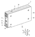
図2及び図3に示されるように、インク収納容器としてのインクカートリッジ1は、内部にインク収納室(液体収納室)11を有する直方体状の筐体(以下、「カートリッジ本体」あるいは「容器本体」ともいう)2を備えている。図2に、インクカートリッジにおける斜視図を示す。図3に、図2のインクカートリッジを分解してそれぞれの内部の構成について示した斜視図を示す。また、図4に、インクが充填された状態のインクカートリッジについての断面図を示す。
(Case configuration)
As shown in FIGS. 2 and 3, an ink cartridge 1 as an ink storage container includes a rectangular parallelepiped housing (hereinafter referred to as “cartridge main body” or “container main body” having an ink storage chamber (liquid storage chamber) 11 therein. 2). FIG. 2 is a perspective view of the ink cartridge. FIG. 3 is a perspective view showing the internal configuration of each of the ink cartridges of FIG. 2 disassembled. FIG. 4 is a cross-sectional view of the ink cartridge in a state where it is filled with ink.

図2において、Y軸方向は、キャリッジ31に対して着脱されるインクカートリッジの奥行き方向であり、カートリッジの装着方向(挿入方向)および取り外し方向(抜去方向)でもある。筐体2は、上面2a、底面2b、前面2c、背面2dおよび左面2eを含む第1筐体部材40と、右面2fを含む第2筐体部材41とを含んで構成される。第2筐体部材41は、第1筐体部材40の開口を塞ぐ蓋部材として機能する。   In FIG. 2, the Y-axis direction is the depth direction of the ink cartridge that is attached to and detached from the carriage 31, and is also the mounting direction (insertion direction) and the removal direction (extraction direction) of the cartridge. The housing 2 includes a first housing member 40 including a top surface 2a, a bottom surface 2b, a front surface 2c, a back surface 2d, and a left surface 2e, and a second housing member 41 including a right surface 2f. The second housing member 41 functions as a lid member that closes the opening of the first housing member 40.

図2、図3及び図4に示されるように、筐体の前面2cには、位置決め部としての位置決め穴6、貫通部としての貫通口27、管挿入部としての管挿入口8が設けられている。位置決め穴6、貫通口27および管挿入口8は、装着部33に設けられた記録装置本体側インターフェース部と接続されるカートリッジ側インターフェース部として機能する。位置決め穴6、貫通口27、管挿入口8は、それぞれ、後述する図5に示される記録装置本体側インターフェース部である位置決めピン53、開封ピン51、インク受け管52に接続される。   As shown in FIGS. 2, 3, and 4, the front surface 2c of the housing is provided with a positioning hole 6 as a positioning portion, a through-hole 27 as a through-hole, and a tube insertion port 8 as a pipe-inserting portion. ing. The positioning hole 6, the through-hole 27, and the tube insertion port 8 function as a cartridge-side interface unit connected to a recording apparatus main body-side interface unit provided in the mounting unit 33. The positioning hole 6, the through hole 27, and the tube insertion port 8 are connected to a positioning pin 53, an opening pin 51, and an ink receiving tube 52, respectively, which are a recording apparatus main body side interface portion shown in FIG.

以下、カートリッジ側インターフェース部を中心にインクカートリッジの構成について説明する。   Hereinafter, the configuration of the ink cartridge will be described focusing on the cartridge-side interface unit.

図2、図3及び図4に示されるように、管挿入口8は、筐体2の前面2cの下部(上面2aよりも底面2bに近い部分)である底面近傍に設けられている。管挿入口8は管挿入路22の一端部に設けられており、管挿入路22の他端部はインク収納室11に接続されている。管挿入路22には、弾性体(例えば環状ゴム)からなるシール部材19が設けられている。   2, 3, and 4, the tube insertion port 8 is provided in the vicinity of the bottom surface, which is a lower portion of the front surface 2 c of the housing 2 (a portion closer to the bottom surface 2 b than the top surface 2 a). The tube insertion port 8 is provided at one end of the tube insertion path 22, and the other end of the tube insertion path 22 is connected to the ink storage chamber 11. The tube insertion path 22 is provided with a seal member 19 made of an elastic body (for example, an annular rubber).

図4に示されるように、インクカートリッジ1が装着部33に装着される前の状態、すなわち、インクカートリッジ1の未使用状態では、封止部材としての管挿入口封止フィルム18が管挿入口8を覆うように管挿入口8の周囲部分に取り付けられている。この管挿入口封止フィルム18は、物流時等のカートリッジ使用前におけるインク漏れを防止するインク漏れ防止手段として機能する。管挿入口封止フィルム18は、インクカートリッジ1の装着の際、インク受け管52により開封される。   As shown in FIG. 4, in a state before the ink cartridge 1 is attached to the attachment portion 33, that is, in an unused state of the ink cartridge 1, the tube insertion port sealing film 18 as a sealing member is the tube insertion port. 8 is attached to a peripheral portion of the tube insertion port 8 so as to cover the tube 8. The tube insertion port sealing film 18 functions as an ink leakage preventing means for preventing ink leakage before using the cartridge during distribution or the like. The tube insertion port sealing film 18 is opened by the ink receiving tube 52 when the ink cartridge 1 is mounted.

図3及び図4に示されるように、大気連通口7および貫通口27は、カートリッジ高さ方向において管挿入口8と位置決め穴6との間に設けられている。つまり、大気連通口7及び貫通口27は、管挿入口8よりも上方で且つ位置決め穴6よりも下方に配置されている。図4に示されるように、大気連通口7と、インク収納室11の内部の空間との間に、大気連通路16が形成されている。   As shown in FIGS. 3 and 4, the atmosphere communication port 7 and the through-hole 27 are provided between the tube insertion port 8 and the positioning hole 6 in the cartridge height direction. That is, the air communication port 7 and the through-hole 27 are disposed above the tube insertion port 8 and below the positioning hole 6. As shown in FIG. 4, an air communication path 16 is formed between the air communication port 7 and the space inside the ink storage chamber 11.

大気連通路16における装置本体側の一端部は大気連通口7であり、大気連通路16の他端部はインク収納室11に接続されている。大気連通路16とインク収納室11との間の接続位置である、大気連通路開口部(連通部)64(図6)には、メニスカス力を有する多孔質部材としてのフィルタ(規制部材)15が配置されている。フィルタ15は、インク収納室11内部の負圧に応じて、大気連通路16からインク収納室11の内部への空気の通過を許容する。また、フィルタ15は、インク収納室11の内部から外部へのインクあるいは空気の通過を阻止する。これにより、大気連通路開口部64からのインクの漏れを抑えることができると共に、インク収納室11内部の負圧が保たれる。また、フィルタ15が大気連通路開口部64に取り付けられることにより、インク収納室11の内部の負圧が大きいときに、インク収納室11内部への空気の通過が許容され、インク収納室11内部に空気が充填される。大気連通路16がインク収納室11と接続されており、大気連通路16とインク収納室11との接続部分にフィルタ15が取り付けられている。ここでは、大気連通路16におけるインク収納室11と連通する流路を覆うように、大気連通路16にフィルタ15が取り付けられている。   One end of the atmosphere communication path 16 on the apparatus main body side is the atmosphere communication port 7, and the other end of the atmosphere communication path 16 is connected to the ink storage chamber 11. A filter (regulating member) 15 as a porous member having a meniscus force is provided in an atmosphere communication passage opening (communication portion) 64 (FIG. 6), which is a connection position between the atmosphere communication passage 16 and the ink storage chamber 11. Is arranged. The filter 15 allows passage of air from the atmosphere communication path 16 to the inside of the ink storage chamber 11 according to the negative pressure inside the ink storage chamber 11. The filter 15 prevents the ink or air from passing from the inside of the ink storage chamber 11 to the outside. Thereby, ink leakage from the atmosphere communication passage opening 64 can be suppressed, and the negative pressure inside the ink storage chamber 11 is maintained. Further, since the filter 15 is attached to the atmosphere communication passage opening 64, when the negative pressure inside the ink storage chamber 11 is large, the passage of air into the ink storage chamber 11 is allowed, and the inside of the ink storage chamber 11 is allowed. Is filled with air. An air communication path 16 is connected to the ink storage chamber 11, and a filter 15 is attached to a connection portion between the air communication path 16 and the ink storage chamber 11. Here, a filter 15 is attached to the atmosphere communication path 16 so as to cover the flow path communicating with the ink storage chamber 11 in the atmosphere communication path 16.

インク収納室11内のインクは、フィルタ15のメニスカス力により保持される。そのため、フィルタ15が機能している間は、インクはフィルタ15によって大気連通路16へ漏れ出すことが阻止され、インク収納室11の内部に保持される。   The ink in the ink storage chamber 11 is held by the meniscus force of the filter 15. For this reason, while the filter 15 is functioning, the ink is prevented from leaking out to the atmosphere communication path 16 by the filter 15 and held inside the ink storage chamber 11.

インクが消費されることでインク収納室11内部の負圧が大きくなり、インク収納室11内部の負圧がフィルタ15のメニスカス力以上に達すると、フィルタ15を介してインク収納室11内部へ空気が供給される。このとき、大気連通路側に位置する大気が、フィルタ15のメニスカスを破りインク収納室11内に導入されることにより、大気がインク収納室11の内部に充填される。   As the ink is consumed, the negative pressure inside the ink storage chamber 11 increases, and when the negative pressure inside the ink storage chamber 11 reaches the meniscus force of the filter 15, the air flows into the ink storage chamber 11 through the filter 15. Is supplied. At this time, the atmosphere located on the atmosphere communication path side breaks the meniscus of the filter 15 and is introduced into the ink storage chamber 11, whereby the atmosphere is filled into the ink storage chamber 11.

インク収納室11内部の負圧が高くなると、大気連通路16を介してインク収納室11に大気が導入されるので、インク収納室11内の負圧が高くなり過ぎることが抑えられる。これにより、インク収納室11の内部の負圧の大きさを一定に保つことができる。従って、インク収納室11内の負圧が高くなり過ぎることに起因して、インク収納室11内部の負圧と、記録ヘッド32内部の負圧との間のバランスが崩れ、インク収納室11から記録ヘッド32へのインク供給に影響が及ぶことを抑えることができる。   When the negative pressure inside the ink storage chamber 11 becomes high, the air is introduced into the ink storage chamber 11 via the atmosphere communication path 16, so that the negative pressure inside the ink storage chamber 11 can be suppressed from becoming too high. Thereby, the magnitude of the negative pressure inside the ink storage chamber 11 can be kept constant. Therefore, due to the negative pressure in the ink storage chamber 11 becoming too high, the balance between the negative pressure in the ink storage chamber 11 and the negative pressure in the recording head 32 is lost, and the ink storage chamber 11 It is possible to suppress the influence on the ink supply to the recording head 32.

また、図3、6に示されるように、大気連通路開口部64から放射状に延びるように、毛管溝(液体供給手段)60がインク収納室11を構成する壁面に形成されている。本実施形態では、インクカートリッジ1における第1筐体部材40を構成する左面2eの内側の面に、毛管溝60が形成されている。   As shown in FIGS. 3 and 6, a capillary groove (liquid supply means) 60 is formed on the wall surface constituting the ink storage chamber 11 so as to extend radially from the atmosphere communication passage opening 64. In the present embodiment, the capillary groove 60 is formed on the inner surface of the left surface 2e constituting the first housing member 40 in the ink cartridge 1.

本実施形態では、インク収納室11に収納されたインクが消費されて負圧が大きくなったとしても、その分インク収納室11の内部に空気が充填されるので、インク収納室11の内部と記録ヘッド32との間の負圧のバランスが保たれる。従って、インク収納室11に収納されたインクをスムーズに記録ヘッド32に供給することができるので、インク収納室11内のインクを使い切ることができる。   In the present embodiment, even if the ink stored in the ink storage chamber 11 is consumed and the negative pressure increases, the ink storage chamber 11 is filled with air accordingly, The negative pressure balance with the recording head 32 is maintained. Accordingly, since the ink stored in the ink storage chamber 11 can be smoothly supplied to the recording head 32, the ink in the ink storage chamber 11 can be used up.

図4に示されるように、インクカートリッジ1が装着部33に装着される前の状態、つまり、インクカートリッジ1の未使用状態では、封止部材としての大気連通口封止フィルム17が大気連通口7を覆うように配置されている。大気連通口封止フィルム17は、図3に示されるように、可撓性部材12の主要面に対して略90°折り曲げられた状態になっている。大気連通口封止フィルム17は、第1筐体部材40に設けられた穴部92を通って第1筐体部材40に設けられた大気連通口7を覆うように第1筐体部材40の内壁縁に密着している。   As shown in FIG. 4, in a state before the ink cartridge 1 is attached to the attachment portion 33, that is, in an unused state of the ink cartridge 1, the atmosphere communication port sealing film 17 as a sealing member is the atmosphere communication port. 7 is arranged so as to cover 7. As shown in FIG. 3, the atmosphere communication port sealing film 17 is bent by approximately 90 ° with respect to the main surface of the flexible member 12. The atmosphere communication port sealing film 17 passes through the hole 92 provided in the first housing member 40 and covers the air communication port 7 provided in the first housing member 40. It is in close contact with the inner wall edge.

インクカートリッジ1の装着の際、貫通口27を介して大気連通口7に挿入される開封ピン51により大気連通口封止フィルム17は開封される。なお、本実施形態では、大気連通口封止フィルム17は可撓性部材12と一体的に構成されているが、この構成に限られるものではなく、例えば、大気連通口封止フィルム17が可撓性部材12とは別部品として構成されていてもよい。   When the ink cartridge 1 is mounted, the atmosphere communication port sealing film 17 is unsealed by the opening pin 51 inserted into the atmosphere communication port 7 through the through-hole 27. In the present embodiment, the atmosphere communication port sealing film 17 is configured integrally with the flexible member 12, but is not limited to this configuration. For example, the air communication port sealing film 17 is possible. The flexible member 12 may be configured as a separate part.

大気連通口封止フィルム17は、物流時等のカートリッジ使用前におけるインク蒸発やインク漏れを抑制する手段として機能する。従って、大気連通口封止フィルム17が開封されるタイミングは、インクカートリッジの使用直前であることが好ましい。そのため本実施形態では、インクカートリッジ1が記録装置本体に装着されるタイミングで大気連通口封止フィルム17が開封されるようにするために、記録装置本体の開封ピン51によって大気連通口封止フィルム17が開封される構成を採用している。   The air communication port sealing film 17 functions as a means for suppressing ink evaporation and ink leakage before using the cartridge during distribution or the like. Therefore, it is preferable that the opening timing of the atmosphere communication port sealing film 17 is immediately before the use of the ink cartridge. Therefore, in this embodiment, the atmosphere communication port sealing film is opened by the opening pin 51 of the recording apparatus main body so that the atmosphere communication port sealing film 17 is opened at the timing when the ink cartridge 1 is mounted on the recording apparatus main body. The structure which 17 is opened is employ | adopted.

(インク収納室の内部の構成)
次に、インク収納室の構成を中心にインクカートリッジの内部構成について説明する。インク収納室11は、第1筐体部材40の内壁面と、この第1筐体部材40の内壁縁に密着された可撓性部材12と、によって構成される内部空間にインクを収納する部屋である。可撓性部材12は、柔軟性のあるシートによって形成されている。インク収納室11の内部には、インクが収納されている。
(Internal structure of ink storage chamber)
Next, the internal configuration of the ink cartridge will be described focusing on the configuration of the ink storage chamber. The ink storage chamber 11 is a chamber that stores ink in an internal space formed by the inner wall surface of the first housing member 40 and the flexible member 12 that is in close contact with the inner wall edge of the first housing member 40. It is. The flexible member 12 is formed of a flexible sheet. Ink is stored in the ink storage chamber 11.

管挿入路22には、シール部材ユニット20が取り付けられる。シール部材ユニット20は、第1筐体部材40に設けられた管挿入路22に嵌め込まれることで、管挿入路22に取り付けられる。シール部材ユニット20は、一端に開閉可能なスリットが設けられ他端が開口している円筒状のシール部材19と、シール部材19の外周面と一体化された外装21とで構成されている。シール部材ユニット20が管挿入路22に挿入されると、シール部材ユニット20が、管挿入口8を構成することになる。   A seal member unit 20 is attached to the tube insertion path 22. The seal member unit 20 is attached to the tube insertion path 22 by being fitted into the tube insertion path 22 provided in the first housing member 40. The seal member unit 20 includes a cylindrical seal member 19 having a slit that can be opened and closed at one end and an opening at the other end, and an exterior 21 integrated with the outer peripheral surface of the seal member 19. When the seal member unit 20 is inserted into the tube insertion path 22, the seal member unit 20 constitutes the tube insertion port 8.

図3に示されるように、インク収納室11の内部には、負圧形成手段としての負圧発生バネ13と、第1筐体部材40の内壁周よりも一回り小さい板部材14とが配置される。また、インクカートリッジ1には、インク収納室11の一部を形成するように、負圧形成手段としての可撓性部材12が配置されている。負圧発生バネ13の一端は第1筐体部材40の左面2e内壁に係合されて、固定的に取り付けられている。また、負圧発生バネ13の他端は、板部材14に固定的に係合されて取り付けられている。負圧発生バネ13は、板部材14を介して可撓性部材12をインク収納室が拡張する方向に付勢することで、インク収納室内を一定の負圧の範囲に維持する。このように、インクカートリッジ1は、インク収納室11に取り付けられた可撓性部材12と、インク収納室11の容積を拡張する方向に付勢する付勢手段としての負圧発生バネ13とを有している。   As shown in FIG. 3, a negative pressure generating spring 13 as a negative pressure generating means and a plate member 14 that is slightly smaller than the inner wall circumference of the first housing member 40 are disposed inside the ink storage chamber 11. Is done. Further, the ink cartridge 1 is provided with a flexible member 12 as a negative pressure forming means so as to form a part of the ink storage chamber 11. One end of the negative pressure generating spring 13 is engaged with the inner wall of the left surface 2e of the first housing member 40 and fixedly attached. The other end of the negative pressure generating spring 13 is fixedly engaged with and attached to the plate member 14. The negative pressure generation spring 13 biases the flexible member 12 through the plate member 14 in the direction in which the ink storage chamber expands, thereby maintaining the ink storage chamber in a certain negative pressure range. As described above, the ink cartridge 1 includes the flexible member 12 attached to the ink storage chamber 11 and the negative pressure generating spring 13 as a biasing unit that biases the ink storage chamber 11 in the direction of expanding the volume. Have.

外部へのインク供給によってインク収納室11内のインクが減少すると、インク収納室11内の負圧は著しく高まろうとする。しかしながら、インク収納室11内のインクの減少に伴い、負圧発生バネ13が縮み、それに伴い板部材14がインク収納室11の内容積を縮小する方向に移動することで負圧の著しい上昇を抑制している。   When the ink in the ink storage chamber 11 decreases due to the supply of ink to the outside, the negative pressure in the ink storage chamber 11 tends to increase significantly. However, as the ink in the ink storage chamber 11 decreases, the negative pressure generating spring 13 contracts, and as a result, the plate member 14 moves in a direction to reduce the internal volume of the ink storage chamber 11, thereby significantly increasing the negative pressure. Suppressed.

(ジョイントユニットの構成)
次に記録装置本体側のインターフェース部について説明する。図5に示されるように、装着部33には、ジョイントユニット59が設けられている。ジョイントユニット59は、インクカートリッジの前面2cに対向可能な立設面に、先端が尖った円柱状の開封ピン51、先細の円柱状で且つ先端に開口を有する中空針であるインク受け管52、先細の円柱状の位置決めピン53などを有している。
(Composition of joint unit)
Next, the interface unit on the recording apparatus main body side will be described. As shown in FIG. 5, the mounting unit 33 is provided with a joint unit 59. The joint unit 59 has a cylindrical opening pin 51 with a pointed tip on a standing surface that can face the front surface 2c of the ink cartridge, an ink receiving tube 52 that is a tapered columnar shape and a hollow needle having an opening at the tip, It has a tapered cylindrical positioning pin 53 and the like.

開封ピン51は、インクカートリッジ1の装着の際、大気連通口封止フィルム17を突き破って大気連通口封止フィルム17を開封する開封部材である。本実施形態においては、開封ピン51はまず貫通口27に挿入され、貫通口27を通過した開封ピン51が大気連通口封止フィルム17を開封すると共に大気連通口7に挿入される。   The opening pin 51 is an opening member that breaks through the air communication port sealing film 17 and opens the air communication port sealing film 17 when the ink cartridge 1 is mounted. In the present embodiment, the opening pin 51 is first inserted into the through hole 27, and the opening pin 51 that has passed through the through hole 27 opens the atmosphere communication port sealing film 17 and is inserted into the atmosphere communication port 7.

開封ピン51には流路が形成され、流路は開封ピン51の先端部で開口している。開封ピン51の内部に形成された流路は、ジョイントユニット59の内部に形成された流路と接続されている。ジョイントユニット59の内部に形成された流路は、流路と大気とが連通する不図示の大気連通口に延びている。このように、開封ピン51の内部に形成された流路は、ジョイントユニット59の内部に形成された流路と接続され、ジョイントユニット59で、流路と大気とが連通している。インクカートリッジ1がジョイントユニット59に取り付けられ、開封ピン51が大気連通口7に挿入されると、開封ピン51内部の流路とインクカートリッジ1における大気連通路16とが接続される。従って、インク収納室11の内部が、大気と連通することになる。   A channel is formed in the unsealing pin 51, and the channel is open at the tip of the unsealing pin 51. The flow path formed inside the opening pin 51 is connected to the flow path formed inside the joint unit 59. The flow path formed inside the joint unit 59 extends to an air communication port (not shown) where the flow path communicates with the atmosphere. Thus, the flow path formed inside the opening pin 51 is connected to the flow path formed inside the joint unit 59, and the flow path and the atmosphere communicate with each other at the joint unit 59. When the ink cartridge 1 is attached to the joint unit 59 and the opening pin 51 is inserted into the atmosphere communication port 7, the flow path inside the opening pin 51 and the atmosphere communication path 16 in the ink cartridge 1 are connected. Therefore, the inside of the ink storage chamber 11 communicates with the atmosphere.

インク受け管52としてのインク受け針は、管挿入口封止フィルム18を突き破って管挿入口封止フィルム18を開封すると共に、管挿入口8に挿入されて管挿入路22と接続し、管挿入路22からインクを受けるインク受け部材である。このインク受け管52は、記録ヘッド32と連通しており、管挿入路22から受けたインクを記録ヘッド32へ供給する。つまり、インク受け管52は、記録ヘッド32へインクを供給するためのインク供給管として機能する。   The ink receiving needle as the ink receiving tube 52 breaks through the tube insertion port sealing film 18 to open the tube insertion port sealing film 18 and is inserted into the tube insertion port 8 to connect to the tube insertion path 22. An ink receiving member that receives ink from the insertion path 22. The ink receiving tube 52 communicates with the recording head 32 and supplies the ink received from the tube insertion path 22 to the recording head 32. That is, the ink receiving tube 52 functions as an ink supply tube for supplying ink to the recording head 32.

位置決めピン53は、位置決め穴6に挿入されて位置決め穴6と嵌合することによって、インクカートリッジ1の前面2cに沿う方向(X軸方向、Z軸方向)への移動を規制するための位置決め部材である。   The positioning pin 53 is inserted into the positioning hole 6 and is fitted to the positioning hole 6 to thereby restrict the movement of the ink cartridge 1 in the direction along the front surface 2c (X-axis direction, Z-axis direction). It is.

図5(a)に示されるように、装着動作の初期において、インクカートリッジ1は装着ガイド58の内側に沿って挿入されていく。図5(a)には、インクカートリッジ1がジョイントユニット59に取り付けられている状態のインクカートリッジ1の断面図が示されている。インクカートリッジ1がジョイントユニット59に取り付けられると、管挿入口封止フィルム18がインク受け管52の先端により開封されると共に、管挿入口8にインク受け管52が挿入される。次いで、位置決め穴6に位置決めピン53が挿入されると共に、2つの位置規制面10が2つの位置決め壁(不図示)により挟み込まれることで、これ以降の位置ずれを抑制する。また、2つの位置規制面10により底面近傍の2箇所が位置規制されると共に、2つの位置規制面10よりも上方にある位置決め穴6により1箇所が位置規制されるので、インクカートリッジ1の移動は概ね規制される。特に、インクカートリッジ1による前面(XZ平面)2cに沿った方向(X軸方向、Z軸方向)およびθy方向への移動を規制することができる。   As shown in FIG. 5A, the ink cartridge 1 is inserted along the inner side of the mounting guide 58 at the initial stage of the mounting operation. FIG. 5A shows a cross-sectional view of the ink cartridge 1 in a state where the ink cartridge 1 is attached to the joint unit 59. When the ink cartridge 1 is attached to the joint unit 59, the tube insertion port sealing film 18 is opened by the tip of the ink receiving tube 52, and the ink receiving tube 52 is inserted into the tube insertion port 8. Next, the positioning pin 53 is inserted into the positioning hole 6 and the two position restricting surfaces 10 are sandwiched between two positioning walls (not shown), thereby suppressing subsequent positional deviation. In addition, two positions in the vicinity of the bottom surface are regulated by the two position regulating surfaces 10 and one position is regulated by the positioning hole 6 above the two position regulating surfaces 10, so that the ink cartridge 1 moves. Are generally regulated. In particular, the movement of the ink cartridge 1 in the direction (X-axis direction, Z-axis direction) along the front surface (XZ plane) 2c and the θy direction can be restricted.

次いで、貫通口27に挿入された開封ピン51により大気連通口封止フィルム17が開封されると共に、大気連通口7に開封ピン51が挿入される。次いで、インク受け管52が管挿入路22内に設けられたシール部材19に挿入されて、これにより、インク収納室11とインク受け管52とが連通する。図5(b)に、ジョイントユニット59へのインクカートリッジ1の装着が完了した状態のインクカートリッジの断面図を示す。   Next, the air communication port sealing film 17 is opened by the opening pin 51 inserted into the through-hole 27, and the opening pin 51 is inserted into the air communication port 7. Next, the ink receiving tube 52 is inserted into the seal member 19 provided in the tube insertion path 22, whereby the ink storage chamber 11 and the ink receiving tube 52 communicate with each other. FIG. 5B is a cross-sectional view of the ink cartridge in a state where the mounting of the ink cartridge 1 to the joint unit 59 is completed.

(記録ヘッドへのインクの供給)
インク収納室11に貯留されたインクが記録ヘッド32に供給される際には、インクが管挿入路22へ移動する。管挿入口8には、インクジェット記録装置の本体側におけるジョイントユニット59のインク受け管52が挿入されており、管挿入路22を通ったインクがインク受け管52の内部に流入する。
(Ink supply to the recording head)
When the ink stored in the ink storage chamber 11 is supplied to the recording head 32, the ink moves to the tube insertion path 22. The ink receiving tube 52 of the joint unit 59 on the main body side of the ink jet recording apparatus is inserted into the tube insertion port 8, and the ink that has passed through the tube insertion path 22 flows into the ink receiving tube 52.

インク収納室11の内部に貯留されたインクが消費されていくと、インク収納室11の内部の負圧が次第に大きくなっていく。記録ヘッド32の内部にインクを保持するためには、記録ヘッド32の内部に適度な負圧が必要となる。そのため、インク収納室11の内部で、負圧発生バネ13によって、板部材14を、インク収納室11が拡張する方向に付勢している。これにより、インク収納室11の内部で負圧を発生させ、この負圧が記録ヘッド32に伝達されている。   As the ink stored in the ink storage chamber 11 is consumed, the negative pressure in the ink storage chamber 11 gradually increases. In order to hold ink inside the recording head 32, an appropriate negative pressure is required inside the recording head 32. Therefore, the plate member 14 is biased in the direction in which the ink storage chamber 11 expands by the negative pressure generating spring 13 inside the ink storage chamber 11. Accordingly, a negative pressure is generated inside the ink storage chamber 11, and this negative pressure is transmitted to the recording head 32.

記録ヘッド32内では、細い流路における毛細管力とインク収納容器内部の負圧との間の平衡によって、吐出口で適切なメニスカスが保持されている。これによって、記録ヘッド32内部にインクが保持されている。   In the recording head 32, an appropriate meniscus is held at the ejection port by the balance between the capillary force in the narrow flow path and the negative pressure inside the ink storage container. As a result, the ink is held inside the recording head 32.

記録ヘッド32の内部に貯留されたインクが吐出され、記録ヘッド32内部のインクが少なくなることで記録ヘッド32内部の負圧が大きくなると、インク収納室11から記録ヘッド32へインクが供給される。   When the ink stored in the recording head 32 is discharged and the negative pressure in the recording head 32 increases due to a decrease in the ink in the recording head 32, the ink is supplied from the ink storage chamber 11 to the recording head 32. .

ここで、インク収納室11の内部のインクが記録ヘッド32に供給されることでインク収納室11内部の負圧が大きくなると、インク収納室11の内部の負圧が過度に大きくなってしまう可能性がある。記録ヘッド32内で負圧が過度に大きくなってしまうと、記録ヘッド32からのインクの吐出に影響を与えてしまう可能性がある。そのため、インク収納室11の内部の負圧が大きくなると、インク収納室11内部の負圧の大きさに応じてインク収納室11の内部に空気が充填される。   Here, if the negative pressure inside the ink storage chamber 11 is increased by supplying the ink inside the ink storage chamber 11 to the recording head 32, the negative pressure inside the ink storage chamber 11 may be excessively increased. There is sex. If the negative pressure becomes excessively large in the recording head 32, there is a possibility that ink ejection from the recording head 32 is affected. Therefore, when the negative pressure inside the ink storage chamber 11 increases, the inside of the ink storage chamber 11 is filled with air according to the magnitude of the negative pressure inside the ink storage chamber 11.

(インク収納室内部への空気の充填)
図6(a)、(b)を用いて、インクが消費されてインク収納室11内部の負圧が大きくなった際にインク収納室11の内部に空気を充填する際のインクカートリッジ1の状態を説明する。図6(a)に、インク収納室11の内部にインクが使用されず、初期状態におけるインクカートリッジ1についての断面図を示す。図6(b)に、インク収納室11の内部のインクが部分的に使用された使用途中状態におけるインクカートリッジ1についての断面図を示す。また、図7(a)に、インクカートリッジ1における、フィルタ15を介してインク収納室11と大気連通路16とが接続される接続位置の周辺についての断面図を示す。図7(b)に、インクカートリッジ1における、大気連通路16からフィルタ15を通ってインク収納室11の内部に空気が充填されている状態のインク収納室11と大気連通路16とが接続される接続位置の周辺についての断面図を示す。図7(c)に、インクカートリッジ1における、大気連通路16からインク収納室11の内部への空気の充填が完了した状態のインク収納室11と大気連通路16とが接続される接続位置の周辺についての断面図を示す。
(Filling the ink storage chamber with air)
6A and 6B, the state of the ink cartridge 1 when air is filled into the ink storage chamber 11 when the ink is consumed and the negative pressure inside the ink storage chamber 11 increases. Will be explained. FIG. 6A shows a cross-sectional view of the ink cartridge 1 in an initial state where no ink is used in the ink storage chamber 11. FIG. 6B is a cross-sectional view of the ink cartridge 1 in the middle of use in which the ink inside the ink storage chamber 11 is partially used. FIG. 7A is a cross-sectional view of the periphery of a connection position in the ink cartridge 1 where the ink storage chamber 11 and the atmosphere communication path 16 are connected via the filter 15. In FIG. 7B, the ink storage chamber 11 and the atmosphere communication passage 16 in the ink cartridge 1 in a state where the air is filled in the ink storage chamber 11 through the filter 15 from the atmosphere communication passage 16 are connected. Sectional drawing about the periphery of the connecting position is shown. FIG. 7C shows a connection position in the ink cartridge 1 where the ink storage chamber 11 and the atmosphere communication passage 16 in a state where the air filling from the atmosphere communication passage 16 to the inside of the ink storage chamber 11 is completed are connected. Sectional drawing about the periphery is shown.

上記したように、インク収納室11からの記録ヘッド32へのインク供給が進むに伴い、インク収納室11内部のインクが減少すると、インク収納室11の内部の負圧が大きくなる。インク収納室11内の負圧がフィルタ15のメニスカス力以上に達すると、大気連通路16からフィルタ15を通過してインク収納室11内に空気が導入される。   As described above, as the ink supply from the ink storage chamber 11 to the recording head 32 proceeds, if the ink in the ink storage chamber 11 decreases, the negative pressure in the ink storage chamber 11 increases. When the negative pressure in the ink storage chamber 11 exceeds the meniscus force of the filter 15, the air is introduced into the ink storage chamber 11 through the air communication path 16 through the filter 15.

上述のように、インク収納室11の内部は、フィルタ15を介して大気連通路16に接続され、大気連通路16は、大気連通口7まで延びている。図5(b)に示されるように、インクカートリッジ1がジョイントユニット59に取り付けられると、大気連通口7にジョイントユニット59の開封ピン51が挿入される。これにより、大気連通路16と開封ピン51及びジョイントユニット59の内部に形成されている流路とが接続され、インク収納室11の内部と大気とが連通する。インク収納室11内部の負圧が大きくなると、大気連通路16、開封ピン51内部の流路及びジョイントユニット59内部の流路を介して、インク収納室11の内部に外部からの空気が充填される。   As described above, the interior of the ink storage chamber 11 is connected to the atmosphere communication path 16 via the filter 15, and the atmosphere communication path 16 extends to the atmosphere communication port 7. As shown in FIG. 5B, when the ink cartridge 1 is attached to the joint unit 59, the opening pin 51 of the joint unit 59 is inserted into the atmosphere communication port 7. As a result, the atmosphere communication path 16 is connected to the flow path formed in the opening pin 51 and the joint unit 59, and the inside of the ink storage chamber 11 communicates with the atmosphere. When the negative pressure inside the ink storage chamber 11 is increased, the air inside the ink storage chamber 11 is filled with air from the outside through the atmosphere communication path 16, the flow path inside the unsealing pin 51, and the flow path inside the joint unit 59. The

ここでフィルタ15は外気を導くための大気連通路16と、これもまた所望の毛細管力を発生しうる毛管溝60の両者に当接している。本実施形態ではフィルタ15はSUSメッシュフィルターを用いているが、好適に利用出来るのであれば、材質は樹脂であっても良いし、形状は不織布タイプであっても良い。フィルタ15は溶着されたリブ61を介して筐体部材111に半溶着されている。   Here, the filter 15 is in contact with both the atmosphere communication path 16 for guiding the outside air and the capillary groove 60 that can also generate a desired capillary force. In this embodiment, the filter 15 uses a SUS mesh filter. However, as long as it can be suitably used, the material may be a resin and the shape may be a non-woven fabric type. The filter 15 is semi-welded to the casing member 111 via the welded rib 61.

ここで、半溶着とは、本実施形態におけるフィルタ15による大気連通路開口部当接面65への溶着の程度によって行われた溶着のことをいうものとする。ここでは、フィルタ15によって、インク収納室11における大気連通路開口部当接面65(図7(a)参照)がシールされている。このとき、フィルタ15と大気連通路開口部当接面65との間の隙間の毛管力が、フィルタ15における最小開口部の毛管力以下であるように、フィルタ15によって大気連通路開口部当接面65がシールされている。   Here, semi-welding refers to welding performed according to the degree of welding to the air communication passage opening contact surface 65 by the filter 15 in the present embodiment. Here, the air communication passage opening contact surface 65 (see FIG. 7A) in the ink storage chamber 11 is sealed by the filter 15. At this time, the filter 15 is in contact with the air communication passage opening so that the capillary force in the gap between the filter 15 and the air communication passage opening contact surface 65 is equal to or less than the capillary force of the minimum opening in the filter 15. Surface 65 is sealed.

本実施形態では、毛管溝60を介してインク収納室11内部のインクをフィルタ15に供給できるように毛管溝60が形成されている。すなわち、毛管溝60からフィルタ15へのインク流路において、インクの供給がスムーズに行われるように、フィルタ15が配置されている。フィルタ15に供給されたインクが、フィルタ内メニスカス形成部66(図7(a)参照)に到達する際に、インクがスムーズにフィルタ内メニスカス形成部66に供給されるように、フィルタ15が配置されている。このように、毛管溝60を介してフィルタ15に供給されたインクがスムーズにフィルタ内メニスカス形成部66に供給されるように、フィルタ15が配置されている。   In the present embodiment, the capillary groove 60 is formed so that the ink inside the ink storage chamber 11 can be supplied to the filter 15 via the capillary groove 60. That is, the filter 15 is arranged so that the ink is smoothly supplied in the ink flow path from the capillary groove 60 to the filter 15. When the ink supplied to the filter 15 reaches the in-filter meniscus forming section 66 (see FIG. 7A), the filter 15 is arranged so that the ink is smoothly supplied to the in-filter meniscus forming section 66. Has been. In this way, the filter 15 is arranged so that the ink supplied to the filter 15 via the capillary groove 60 is smoothly supplied to the in-filter meniscus forming portion 66.

ここで、記録ヘッド32からインクが吐出され、記録ヘッド32に負圧が生じると、インク収納室11から記録ヘッド32にインクが供給される。その際、インクカートリッジ1の管挿入路22からインク受け管52を介してジョイントユニット59にインクが供給され、記録ヘッド32にインクが供給される。   Here, when ink is ejected from the recording head 32 and a negative pressure is generated in the recording head 32, the ink is supplied from the ink storage chamber 11 to the recording head 32. At that time, ink is supplied from the tube insertion path 22 of the ink cartridge 1 to the joint unit 59 via the ink receiving tube 52, and ink is supplied to the recording head 32.

記録ヘッド32にインクが供給されると、図6(b)に示されるようにインク収納室11内のインクの体積が減少する。それに伴い板部材14は、負圧発生バネ13を圧縮しつつ、板部材変位方向80の方向へ移動する。また、板部材14が板部材変位方向80へ移動するのに伴い、インク収納室11内負圧の絶対値も上昇する。   When ink is supplied to the recording head 32, the volume of the ink in the ink storage chamber 11 decreases as shown in FIG. 6B. Accordingly, the plate member 14 moves in the direction of the plate member displacement direction 80 while compressing the negative pressure generating spring 13. Further, as the plate member 14 moves in the plate member displacement direction 80, the absolute value of the negative pressure in the ink storage chamber 11 also increases.

インクの消費が進み、インク収納室11内部の負圧の絶対値が大きくなることにより、インク収納室11内部の負圧がフィルタ15の持つ毛細管力の絶対値よりも大きくなると、空気がインク収納室11内部に送り込まれる。このとき、インク収納室11の内部の負圧がフィルタ15の毛細管力の絶対値よりも大きくなることで、大気連通路16内の大気とインク収納室11内部の圧力との差圧が大きくなる。そのため、図7(b)に示されるように、大気連通路16内の空気が、フィルタ内メニスカス形成部66のメニスカスを破り、フィルタ15を通ってインク収納室11の内部に空気93が充填される。   When the ink consumption progresses and the absolute value of the negative pressure inside the ink storage chamber 11 increases, and the negative pressure inside the ink storage chamber 11 becomes larger than the absolute value of the capillary force of the filter 15, the air is stored in the ink. It is sent into the chamber 11. At this time, the negative pressure inside the ink storage chamber 11 becomes larger than the absolute value of the capillary force of the filter 15, thereby increasing the differential pressure between the atmosphere in the atmosphere communication path 16 and the pressure inside the ink storage chamber 11. . Therefore, as shown in FIG. 7B, the air in the atmosphere communication path 16 breaks the meniscus of the in-filter meniscus forming portion 66 and passes through the filter 15 to fill the inside of the ink storage chamber 11 with air 93. The

図7(a)に示される状態からインク収納室11内部でさらにインクの消費が進み、インク収納室11内負圧の絶対値がフィルタ15の持つ毛細管力の絶対値を上回ったときに、インク収納室11内部に空気が充填される。このとき、図7(b)に示されるように、空気93によってフィルタ内メニスカス形成部66でのインクによるメニスカスが破られて、インク収納室11の内部に空気93が充填される。   When the consumption of ink further proceeds in the ink storage chamber 11 from the state shown in FIG. 7A and the absolute value of the negative pressure in the ink storage chamber 11 exceeds the absolute value of the capillary force of the filter 15, the ink The interior of the storage chamber 11 is filled with air. At this time, as shown in FIG. 7B, the meniscus due to the ink in the meniscus forming portion 66 in the filter is broken by the air 93, and the air 93 is filled in the ink storage chamber 11.

大気連通路16から空気が、フィルタ15の空気排出面81を通過し、インク収納室11内に導入される(図7(b))。インクの消費が行われると共にインク収納室11内部への空気の充填が続くと、それに伴いインクの液面が低下する。従って、フィルタ15は、インクの液面の上方に位置し、フィルタ15が充填された大気83に曝露される。フィルタ15よりも液面が下方に位置する場合に空気がインク収納室11に充填される際には、空気がフィルタ15を通過する度に、フィルタ内メニスカス形成部66に存在するインクが飛散し、インクがフィルタ15から失われていく。しかしながら、フィルタ内メニスカス形成部66には、毛管溝60の方向90に沿ってインクが供給されて補充される。そのため、メニスカスが破られた後、フィルタ15から失われた分のインクが、フィルタ15にすぐに供給される。従って、フィルタ15で、迅速にメニスカスが再形成される(図6(b)、(c))。   Air from the atmosphere communication path 16 passes through the air discharge surface 81 of the filter 15 and is introduced into the ink storage chamber 11 (FIG. 7B). When ink is consumed and air is continuously filled in the ink storage chamber 11, the ink level is lowered accordingly. Therefore, the filter 15 is located above the ink level and is exposed to the atmosphere 83 filled with the filter 15. When the ink storage chamber 11 is filled with air when the liquid level is located below the filter 15, the ink present in the in-filter meniscus forming portion 66 is scattered every time the air passes through the filter 15. Ink is lost from the filter 15. However, ink is supplied to the in-filter meniscus forming portion 66 along the direction 90 of the capillary groove 60 and is replenished. Therefore, after the meniscus is broken, the ink lost from the filter 15 is immediately supplied to the filter 15. Accordingly, the meniscus is rapidly re-formed by the filter 15 (FIGS. 6B and 6C).

本実施形態では、毛管溝60が、インク収納室底面62付近に存在し、また、インクの液面の下方からフィルタ15の位置まで延びている。毛管溝60は、フィルタ15に接するように形成されている。本実施形態では、毛管溝60により、インクの貯留されている部分からフィルタ15の配置された位置までインクを引き上げるのに十分な毛細管力が毛管溝60内で形成される。本実施形態では、毛管溝60は、幅・深さ共に、0.10mm〜0.25mmに形成されている。なお、毛管溝60のサイズとしては、上記のものに限定されない。インクの表面張力、及び吊り上げる高さにも依るが、インクの貯留されている部分からフィルタ15までインクを引き上げるのに十分な毛細管力を形成できるのであれば他の大きさであってもよい。   In the present embodiment, the capillary groove 60 exists in the vicinity of the bottom surface 62 of the ink storage chamber, and extends from below the ink level to the position of the filter 15. The capillary groove 60 is formed in contact with the filter 15. In this embodiment, the capillary groove 60 forms a capillary force in the capillary groove 60 sufficient to pull up the ink from the portion where the ink is stored to the position where the filter 15 is disposed. In the present embodiment, the capillary groove 60 is formed with a width and a depth of 0.10 mm to 0.25 mm. The size of the capillary groove 60 is not limited to the above. Although depending on the surface tension of the ink and the height of lifting, other sizes may be used as long as a capillary force sufficient to pull up the ink from the ink storage portion to the filter 15 can be formed.

また、本実施形態では、毛管溝60が、インク収納室11の内部に複数配置され、複数の毛管溝60がフィルタ15から外側に向かって放射状に延びている。図8(a)〜(d)に、インクカートリッジ1における、インクの位置し得る領域と、毛管溝60との間の関係について示した断面図を示す。図8(a)〜(d)に示されるように、インクカートリッジ1が姿勢を変えたとしても、複数の毛管溝60のうちのいずれかの毛管溝60の一部が、インクの貯留されている領域のいずれかの部分に位置している。   In the present embodiment, a plurality of capillary grooves 60 are arranged inside the ink storage chamber 11, and the plurality of capillary grooves 60 extend radially outward from the filter 15. FIGS. 8A to 8D are cross-sectional views showing the relationship between the region where ink can be located and the capillary groove 60 in the ink cartridge 1. As shown in FIGS. 8A to 8D, even when the ink cartridge 1 changes its posture, a part of the capillary groove 60 among the plurality of capillary grooves 60 is stored with ink. It is located in any part of the area.

図8(a)は、インクカートリッジ1が、インクジェット記録装置に搭載された状態の、通常の姿勢で配置されている際の断面図である。図8(a)に示される状態では、フィルタ15から下方に延びた2本の毛管溝60Aが、インクの貯留されている部分まで延びている。   FIG. 8A is a cross-sectional view when the ink cartridge 1 is disposed in a normal posture in a state of being mounted on the ink jet recording apparatus. In the state shown in FIG. 8A, the two capillary grooves 60A extending downward from the filter 15 extend to a portion where ink is stored.

図8(a)に示される状態では、インク収納室11内部のインクが消費されてインク収納室11で最も液面が低下したときの液面の位置が、インク残留可能領域95の上面の位置として示されている。インク残留可能領域95、96は、インク収納室11の内部のインクが消費されてインク収納室11の内部のインクが最も少なくなったときに、インクが位置し得る領域のことである。インク残留可能領域95は、インクカートリッジ1が記録装置本体側のジョイントユニット59に搭載された際の姿勢で、インク収納室11の内部のインクが最も少なくなったときに、インクが位置し得る領域のことである。   In the state shown in FIG. 8A, the position of the liquid level when the ink in the ink storage chamber 11 is consumed and the liquid level is the lowest in the ink storage chamber 11 is the position of the upper surface of the remaining ink area 95. Is shown as The remaining ink areas 95 and 96 are areas where ink can be located when the ink in the ink storage chamber 11 is consumed and the ink in the ink storage chamber 11 becomes the least. The ink remaining possible area 95 is an attitude when the ink cartridge 1 is mounted on the joint unit 59 on the recording apparatus main body side, and the ink can be located when the ink in the ink storage chamber 11 becomes the least. That is.

図8(a)には、インクが最も少なくなった状態で、インクが残留することが可能な領域であるインク残留可能領域95、96について示されている。インク残留可能領域96は、インクカートリッジ1が記録装置本体側のジョイントユニット59に搭載されたとき以外の姿勢で、インク収納室11の内部のインクが最も少なくなったときに、インクが位置し得る領域のことである。   FIG. 8A shows ink remaining possible regions 95 and 96 that are regions where ink can remain in a state where ink is at a minimum. The remaining ink area 96 can be positioned when the ink in the ink storage chamber 11 is at a minimum in a posture other than when the ink cartridge 1 is mounted on the joint unit 59 on the recording apparatus main body side. It is an area.

図8(a)には、様々な姿勢でのそれぞれのインク残留可能領域95、96について、それぞれの姿勢についてのそれぞれのインク残留可能領域95、96が足し合わされた部分が示されている。   FIG. 8A shows a portion where the remaining ink remaining areas 95 and 96 in the various postures are added to the remaining ink remaining areas 95 and 96 in the respective postures.

図8(a)では、インク収納室11内部におけるインクの液面が、通常姿勢におけるインク残留可能領域95まで低下し、フィルタ15近傍にインクが存在しなくなっている。このような場合であっても、フィルタ15と通常姿勢におけるインク残留可能領域95に存在するインクとの間が、毛管溝60によって連通されている。従って、毛管溝60での毛細管力によって通常姿勢におけるインク残留可能領域95に貯留されているインクがフィルタ15まで引き上げられる。これにより、フィルタ15にインクが供給され続け、迅速なメニスカス復帰を実現することができる。   In FIG. 8A, the ink level in the ink storage chamber 11 is lowered to the ink remaining area 95 in the normal posture, and no ink exists in the vicinity of the filter 15. Even in such a case, the capillary 15 communicates with the filter 15 and the ink existing in the remaining ink area 95 in the normal posture. Therefore, the ink stored in the remaining ink area 95 in the normal posture is pulled up to the filter 15 by the capillary force in the capillary groove 60. As a result, ink is continuously supplied to the filter 15 and a quick meniscus recovery can be realized.

仮に、毛管溝60が形成されていない場合には、インク収納室11内部のインクがフィルタ15に引き上げられずに、フィルタ15に空気が残留してしまう可能性がある。フィルタ15に空気が残留した場合には、そこから、フィルタ15を介してインク収納室11の内部に予期せず空気が入り込む可能性がある。この場合、インク収納室11内部の負圧があまり大きくなっていないにも関わらず、インク収納室11の内部に空気が入り込む可能性がある。このように、インク収納室11内部の負圧が大きくなっていないにも関わらずインク収納室11の内部に空気が入り込むと、インク収納室11内部で負圧が維持できなくなる可能性がある。これによって、インク収納室11の内部の負圧と記録ヘッド32内部の負圧及び毛細管力との間でバランスを保つことができなくなる可能性がある。そのため、記録ヘッド32及びインク収納室11内部にインクを保持できず、記録ヘッド32の吐出口からインクが落下してしまう可能性がある。   If the capillary groove 60 is not formed, the ink inside the ink storage chamber 11 may not be pulled up to the filter 15 and air may remain in the filter 15. If air remains in the filter 15, there is a possibility that air may unexpectedly enter the ink storage chamber 11 through the filter 15. In this case, although the negative pressure inside the ink storage chamber 11 is not so large, air may enter the inside of the ink storage chamber 11. As described above, even if the negative pressure inside the ink storage chamber 11 is not increased, if air enters the ink storage chamber 11, the negative pressure may not be maintained inside the ink storage chamber 11. As a result, there is a possibility that a balance cannot be maintained between the negative pressure inside the ink storage chamber 11 and the negative pressure and capillary force inside the recording head 32. For this reason, the ink cannot be held inside the recording head 32 and the ink storage chamber 11, and the ink may drop from the ejection port of the recording head 32.

本実施形態では、インクカートリッジ1において、インクジェット記録装置に搭載されたときの姿勢で、インク収納室11に貯留されているインクの位置し得る最も低い位置の液面の下方まで毛管溝60が延びている。従って、インクジェット記録装置に搭載されたときの姿勢で、インク収納室11に貯留されているインクの位置し得る最も低い位置の液面の下方の領域に、毛管溝60が位置している。そのため、インクカートリッジ1がインクジェット記録装置に搭載された状態で、インク収納室11内部のインクが消費され尽くされ、インクの液面が、位置し得る最も低い位置の液面となったときであっても、インクと毛管溝60とが接している。従って、そのようなときであっても、毛管溝60による毛細管力によって、フィルタ15にインクを供給することができる。   In this embodiment, in the ink cartridge 1, the capillary groove 60 extends to a position below the lowest liquid level where the ink stored in the ink storage chamber 11 can be positioned in the posture when mounted on the ink jet recording apparatus. ing. Accordingly, the capillary groove 60 is located in the region below the lowest liquid level where the ink stored in the ink storage chamber 11 can be positioned in the posture when mounted on the ink jet recording apparatus. Therefore, when the ink cartridge 1 is mounted on the ink jet recording apparatus, the ink in the ink storage chamber 11 is completely consumed, and the ink level becomes the lowest possible level. However, the ink and the capillary groove 60 are in contact with each other. Accordingly, even in such a case, the ink can be supplied to the filter 15 by the capillary force by the capillary groove 60.

また、本実施形態では、インクカートリッジ1において、取り得る全ての姿勢において、インク収納室11に貯留されているインクの位置し得る最も低い位置の液面の下方まで毛管溝60が延びている。従って、取り得る全ての姿勢で、インク収納室11に貯留されているインクの位置し得る最も低い位置の液面の下方の領域に、毛管溝60が位置している。そのため、インクカートリッジ1の姿勢に関わらず、インク収納室11内部のインクが消費され尽くされ、インクの液面が、位置し得る最も低い位置の液面となったときに、インクと毛管溝60とが接している。従って、インク収納室11内部のインクが消費され尽くされたときであっても、毛管溝60による毛細管力によって、フィルタ15にインクを供給することができる。   In this embodiment, the capillary groove 60 extends below the lowest liquid level where the ink stored in the ink storage chamber 11 can be located in all possible postures of the ink cartridge 1. Therefore, in all possible postures, the capillary groove 60 is located in the region below the lowest liquid level where the ink stored in the ink storage chamber 11 can be located. Therefore, regardless of the posture of the ink cartridge 1, when the ink in the ink storage chamber 11 is exhausted and the ink level becomes the lowest possible level, the ink and the capillary groove 60. And is touching. Therefore, even when the ink in the ink storage chamber 11 is completely consumed, the ink can be supplied to the filter 15 by the capillary force generated by the capillary groove 60.

図8(b)に、インクカートリッジ1が、図8(a)に示される状態から姿勢を変えた際のインクカートリッジ1の断面図を示す。図8(b)に示されるように、インクカートリッジ1の姿勢が傾いたとしても、消費されて最後にインクが残る部分における液面よりも下方の位置に毛管溝60Bが延びている。そのため、インクカートリッジ1が姿勢を変えても毛管溝60がインクと接しており、毛管溝60の毛細管力によってインクをフィルタ15に供給することができる。   FIG. 8B shows a cross-sectional view of the ink cartridge 1 when the posture of the ink cartridge 1 is changed from the state shown in FIG. As shown in FIG. 8B, even if the posture of the ink cartridge 1 is inclined, the capillary groove 60B extends to a position below the liquid level in the portion where ink is consumed and finally remains. Therefore, the capillary groove 60 is in contact with the ink even when the posture of the ink cartridge 1 is changed, and the ink can be supplied to the filter 15 by the capillary force of the capillary groove 60.

また、さらにインクカートリッジ1が姿勢を変えた状態のインクカートリッジ1の断面図について、図8(c)、(d)に示す。図8(c)に示される状態では、インクカートリッジ1が図8(b)に示される状態よりもさらに傾いて、インクカートリッジ1の側面が下方に位置している。また、図8(d)に示される状態では、インクカートリッジ1がそこからさらに傾いて、インクカートリッジ1の搭載状態における上面が下方に位置している。図8(c)に示される状態のときにも、毛管溝60Cが、消費されて最後にインクが残る部分における液面よりも下方の位置まで延びている。そのため、インクカートリッジ1が図8(c)に示される状態まで姿勢を変えても、毛管溝60がインクと接しており、毛管溝60の毛細管力によってインクをフィルタ15に供給することができる。また、図8(d)に示される状態のときにも、毛管溝60Dが、消費されて最後にインクが残る部分における液面よりも下方の位置まで延びている。そのため、インクカートリッジ1が図8(d)に示される状態まで姿勢を変えても、毛管溝60がインクと接しており、毛管溝60の毛細管力によってインクをフィルタ15に供給することができる。   8C and 8D are sectional views of the ink cartridge 1 in a state where the posture of the ink cartridge 1 is further changed. In the state shown in FIG. 8C, the ink cartridge 1 is further inclined than in the state shown in FIG. 8B, and the side surface of the ink cartridge 1 is positioned below. Further, in the state shown in FIG. 8D, the ink cartridge 1 is further tilted therefrom, and the upper surface in the mounted state of the ink cartridge 1 is positioned below. Also in the state shown in FIG. 8C, the capillary groove 60C extends to a position below the liquid level in the portion where ink is consumed and finally remains. Therefore, even if the posture of the ink cartridge 1 is changed to the state shown in FIG. 8C, the capillary groove 60 is in contact with the ink, and the ink can be supplied to the filter 15 by the capillary force of the capillary groove 60. Also in the state shown in FIG. 8D, the capillary groove 60D extends to a position below the liquid level in the portion where ink is consumed and finally remains. Therefore, even if the posture of the ink cartridge 1 is changed to the state shown in FIG. 8D, the capillary groove 60 is in contact with the ink, and the ink can be supplied to the filter 15 by the capillary force of the capillary groove 60.

毛管溝60がフィルタ15から外側に向かって放射状に延びていることから、インクカートリッジ1が通常使用時姿勢とは異なる、どのような姿勢になっても、毛管溝60が、貯留されているインクに接触することができる。従って、インクカートリッジ1がどのような姿勢になっても、フィルタ15にインクを供給することができる。インクカートリッジ1の姿勢に関わらず、フィルタ15にインクを確実に供給することができるので、フィルタ15が空気に晒されることを抑えることができる。従って、インクカートリッジ1が姿勢を変えても、フィルタ15に空気が残留することを抑えることができ、フィルタ15に空気が残留することを確実に抑えることができる。   Since the capillary groove 60 extends radially outward from the filter 15, the ink stored in the capillary groove 60 regardless of the posture of the ink cartridge 1 different from the normal use posture. Can contact. Therefore, the ink can be supplied to the filter 15 regardless of the posture of the ink cartridge 1. Regardless of the attitude of the ink cartridge 1, the ink can be reliably supplied to the filter 15, so that the filter 15 can be prevented from being exposed to air. Therefore, even if the posture of the ink cartridge 1 is changed, it is possible to suppress the air from remaining in the filter 15 and to reliably suppress the air from remaining in the filter 15.

さらに、本実施形態では、毛管溝60によるフィルタ15へのインクの供給は、フィルタ15の、大気連通路16との当接面側に向けて行われている。従って、毛管溝60によるフィルタ15へのインクの供給は、空気の充填の行われている側の面とは反対側の面で行われる。フィルタ15へのインク供給の行われている面とは反対側の面で、フィルタ15の空気排出面81でのインク収納室11側でのインク収納室11内部への空気の充填が行われることにより、フィルタ15へのインクの供給が阻害されることが抑えられる。従って、記録ヘッド32からのインクの吐出の増大によって記録ヘッド32へのインク流量が増大することによりインク収納室11内部への空気の充填が連続的に行われた場合であっても、インクをフィルタ15に十分に供給することができる。インクがフィルタ15に確実に供給されるので、インク収納室11内部に空気が充填された際に迅速にメニスカス復帰を行うことができる。従って、インク収納室11の内部に空気が充填された際にメニスカスの復帰が遅れることによって負圧が喪失されることを抑えることができる。   Further, in the present embodiment, the supply of ink to the filter 15 by the capillary groove 60 is performed toward the contact surface side of the filter 15 with the atmosphere communication path 16. Accordingly, ink is supplied to the filter 15 by the capillary groove 60 on the surface opposite to the surface on which air is filled. Air is filled into the ink storage chamber 11 on the ink storage chamber 11 side on the air discharge surface 81 of the filter 15 on the surface opposite to the surface where the ink is supplied to the filter 15. This prevents the ink supply to the filter 15 from being hindered. Accordingly, even when the ink storage chamber 11 is continuously filled with air by increasing the ink flow rate to the recording head 32 due to the increase in ink discharge from the recording head 32, the ink is discharged. The filter 15 can be sufficiently supplied. Since the ink is reliably supplied to the filter 15, the meniscus can be quickly returned when the ink storage chamber 11 is filled with air. Therefore, it is possible to suppress the loss of the negative pressure due to the delay of the meniscus return when the ink storage chamber 11 is filled with air.

なお、大気連通路16の高さについては、インクカートリッジ1が通常使用時姿勢とは異なる、どのような姿勢になっても、フィルタ15へのインクの供給を確実に行うことが可能な位置に配置されている。   It should be noted that the height of the atmosphere communication path 16 is set at a position where the ink cartridge 1 can be reliably supplied with ink regardless of the posture when the ink cartridge 1 is different from the posture during normal use. Has been placed.

図8(a)に示されるように、大気連通路16と、インクカートリッジ1がインクジェット記録装置に搭載されたときの通常姿勢におけるインク残留可能領域95との間の距離をHとする。また、大気連通路16とその他姿勢におけるインク残留可能領域96との間の距離をそれぞれI、J、Kとする。このとき、本実施形態では、H>I、H>J、H>Kの関係が成立するように毛管溝60が形成されている。つまり、通常姿勢における、大気連通路16とインク残留可能領域95との間の距離Hが、その他の姿勢における大気連通路16とインク残留可能領域96との間の距離I、J、Kよりも大きいように大気連通路16が形成されると共に、毛管溝60が形成されている。   As shown in FIG. 8A, the distance between the atmosphere communication path 16 and the remaining ink area 95 in the normal posture when the ink cartridge 1 is mounted on the ink jet recording apparatus is H. The distances between the atmosphere communication path 16 and the remaining ink remaining area 96 in other postures are I, J, and K, respectively. At this time, in this embodiment, the capillary groove 60 is formed so that the relationship of H> I, H> J, and H> K is established. In other words, the distance H between the atmosphere communication path 16 and the ink remaining possibility area 95 in the normal posture is larger than the distances I, J, and K between the atmosphere communication path 16 and the ink remaining possibility area 96 in the other attitudes. An air communication passage 16 is formed to be large, and a capillary groove 60 is formed.

このように、通常姿勢では、毛管溝60が、貯留されているインクに確実に接するように毛管溝60が形成されている。また、その他のどのような姿勢であっても、毛管溝60が貯留されている領域に確実に接するように、毛管溝60が形成されている。このように毛管溝60が形成されているので、インクカートリッジ1がどのような姿勢になっても、フィルタ15にインクが確実に供給される。従って、フィルタ15が空気に晒されることが抑えられ、予期せず、フィルタ15を介してインク収納室11の内部に空気が入り込むことを抑えることができる。   Thus, in the normal posture, the capillary groove 60 is formed so that the capillary groove 60 is surely in contact with the stored ink. Further, in any other posture, the capillary groove 60 is formed so as to be surely in contact with the region where the capillary groove 60 is stored. Since the capillary groove 60 is thus formed, the ink is reliably supplied to the filter 15 regardless of the posture of the ink cartridge 1. Therefore, the filter 15 is prevented from being exposed to air, and air can be prevented from entering the ink storage chamber 11 through the filter 15 unexpectedly.

本実施形態では、インク使用時のフィルタ15の毛細管力の絶対値は、160mmAq付近である。また、インクカートリッジ1の底面から大気連通路16のまでの距離は、16〜20mmである。このように、本実施形態では、フィルタ15にインクを供給するために毛管溝60が設けられているので、フィルタ15にインクを確実に供給することができる。従って、フィルタ15に空気が残留することを確実に抑えることができる。フィルタ15への空気の残留を抑えることができるので、負圧があまり大きくなっていないにも関わらずインク収納室11の内部に空気が予期せず充填されることを抑えることができる。負圧があまり大きくなっていないにも関わらず空気がインク収納室11の内部に充填されることを抑えることができるので、インク収納室11の内部の負圧を保つことができる。これにより、インク収納室11の内部の負圧と記録ヘッド32との間の負圧のバランスが保たれ、インク収納室11及び記録ヘッド32でのインクの保持を確実に行うことができる。また、記録ヘッド32からのインクの吐出が、インク収納室11の内部での負圧の喪失によって影響を受けることを抑えることができるので、記録ヘッド32からのインクの吐出量を所望の量に保つことができ、安定してインクの吐出を行うことができる。従って、記録によって得られる記録画像の品質を高く維持することができる。   In this embodiment, the absolute value of the capillary force of the filter 15 when ink is used is around 160 mmAq. Further, the distance from the bottom surface of the ink cartridge 1 to the atmosphere communication path 16 is 16 to 20 mm. Thus, in this embodiment, since the capillary groove 60 is provided to supply the ink to the filter 15, the ink can be reliably supplied to the filter 15. Therefore, it is possible to reliably suppress air from remaining in the filter 15. Since the remaining of air in the filter 15 can be suppressed, it is possible to suppress the air from being unexpectedly filled in the ink storage chamber 11 even though the negative pressure is not so high. Since the air can be prevented from being filled in the ink storage chamber 11 even though the negative pressure is not so high, the negative pressure in the ink storage chamber 11 can be maintained. Thereby, the balance between the negative pressure inside the ink storage chamber 11 and the negative pressure between the recording head 32 is maintained, and the ink storage chamber 11 and the recording head 32 can reliably hold the ink. In addition, since it is possible to suppress the ink ejection from the recording head 32 from being affected by the loss of the negative pressure inside the ink storage chamber 11, the ink ejection amount from the recording head 32 can be set to a desired amount. Ink can be stably discharged. Therefore, the quality of the recorded image obtained by recording can be maintained high.

(第2実施形態)
次に、本発明の第2実施形態に係るインクカートリッジについて説明する。なお、上記第1実施形態と同様に構成される部分については図中同一符号を付して説明を省略し、異なる部分についてのみ説明する。
(Second Embodiment)
Next, an ink cartridge according to a second embodiment of the present invention will be described. In addition, about the part comprised similarly to the said 1st Embodiment, the same code | symbol is attached | subjected in a figure, description is abbreviate | omitted, and only a different part is demonstrated.

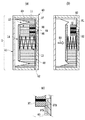
図9に、第2実施形態に係るインクカートリッジについての断面図を示す。図9(a)に、第2実施形態に係るインクカートリッジにおいて、インクが十分に貯留されている状態のインクカートリッジの断面図について示されている。また、図9(b)に、インクが消費されている状態のインクカートリッジの断面図について示されている。   FIG. 9 shows a cross-sectional view of an ink cartridge according to the second embodiment. FIG. 9A shows a cross-sectional view of the ink cartridge according to the second embodiment in a state where ink is sufficiently stored. FIG. 9B shows a cross-sectional view of the ink cartridge in a state where ink is consumed.

第1実施形態では、大気連通路16と、インク収納室11との間の接続位置に、SUSメッシュフィルターによって形成されたフィルタ15が配置されている。これに対し、第2実施形態では、大気連通路16と、インク収納室11との間の接続位置に、発泡ポリウレタン、PP繊維集合体、メラミン樹脂、オレフィン樹脂焼結体等によって形成された吸収体97が配置されている。吸収体97によっても、貯留されているインクを、インク収納室11と大気連通路16との間の接続位置に引き上げて、インク収納室11内部の負圧を一定に保つことができる。   In the first embodiment, a filter 15 formed of a SUS mesh filter is disposed at a connection position between the atmosphere communication path 16 and the ink storage chamber 11. On the other hand, in the second embodiment, absorption formed by foamed polyurethane, PP fiber aggregate, melamine resin, olefin resin sintered body, etc. at the connection position between the atmosphere communication path 16 and the ink storage chamber 11. A body 97 is arranged. Also by the absorber 97, the stored ink can be pulled up to the connection position between the ink storage chamber 11 and the atmosphere communication path 16, and the negative pressure inside the ink storage chamber 11 can be kept constant.

本実施形態の吸収体97は、第1実施形態のフィルタ15よりも厚く形成されている。吸収体97が、複数のカシメピン98により、インク収納室11を形成する壁面に取り付けられている。吸収体97は、第1実施形態のフィルタ15と同等の機能を有しているが、保持できるインク量がフィルタ15に比べて多い。   The absorber 97 of this embodiment is formed thicker than the filter 15 of the first embodiment. The absorber 97 is attached to the wall surface forming the ink storage chamber 11 by a plurality of caulking pins 98. The absorber 97 has the same function as the filter 15 of the first embodiment, but the amount of ink that can be held is larger than that of the filter 15.

さらに、第2実施形態の吸収体97は、第1実施形態のフィルタ15よりも広い面で毛管溝60と接している。図9(c)に、吸収体97の周辺について拡大して示したインクカートリッジの断面図を示す。   Furthermore, the absorber 97 of the second embodiment is in contact with the capillary groove 60 on a surface wider than the filter 15 of the first embodiment. FIG. 9C shows a cross-sectional view of the ink cartridge enlarged around the absorber 97.

本実施形態では、図9(c)に示されるように、吸収体97の底面97Aの一部と、吸収体97の背面97Bの一部とで、毛管溝60と接している。このように、より多くの部分で、吸収体97が毛管溝60と接しているので、毛管溝60によって引き上げられたインクを吸収体97により確実に供給することができる。より確実にインクを吸収体97に供給することができるので、吸収体97に空気が残留することをより確実に抑えることができる。また、より迅速なメニスカス復帰を実現することができるので、インク収納室11から記録ヘッド32に供給されるインクがより高流量な形式のインクカートリッジとすることが可能である。   In this embodiment, as shown in FIG. 9C, a part of the bottom surface 97 </ b> A of the absorber 97 and a part of the back surface 97 </ b> B of the absorber 97 are in contact with the capillary groove 60. Thus, since the absorber 97 is in contact with the capillary groove 60 in more portions, the ink pulled up by the capillary groove 60 can be reliably supplied by the absorber 97. Since ink can be supplied to the absorber 97 more reliably, it is possible to more reliably suppress air from remaining in the absorber 97. In addition, since a quicker meniscus recovery can be realized, an ink cartridge with a higher flow rate of ink supplied from the ink storage chamber 11 to the recording head 32 can be obtained.

なお、上記実施形態では、毛管溝60によって、フィルタ15あるいは吸収体97までインクを引き上げて供給することとしたが、本発明はこれに限定されない。貯留されているインクを、フィルタ15あるいは吸収体97に引き上げることができるのであれば、他の手段によってインクを引き上げて、フィルタ15あるいは吸収体97にインクを供給してもよい。例えば、毛管溝60の替わりに、棒状の多孔質体(吸収体等)が用いられてもよい。棒状の多孔質体が用いられても、毛細管力によって、インクをフィルタ15あるいは吸収体97まで引き上げることができる。   In the above embodiment, the ink is pulled up and supplied to the filter 15 or the absorber 97 by the capillary groove 60, but the present invention is not limited to this. If the stored ink can be pulled up to the filter 15 or the absorber 97, the ink may be pulled up by other means and supplied to the filter 15 or the absorber 97. For example, instead of the capillary groove 60, a rod-like porous body (absorber or the like) may be used. Even if a rod-like porous body is used, the ink can be pulled up to the filter 15 or the absorber 97 by capillary force.

11 インク収納室
12 可撓性部材
13 負圧発生バネ13
15 フィルタ
60 毛管溝
64 大気連通路開口部
11 Ink storage chamber 12 Flexible member 13 Negative pressure generating spring 13
15 Filter 60 Capillary groove 64 Air communication passage opening

Claims (8)

液体を収納する液体収納室と、
前記液体収納室に形成され、外部と前記液体収納室とが連通する連通部と、
前記液体収納室の内部で負圧を形成する負圧形成手段と、
前記連通部に取り付けられ、前記液体収納室の内部の負圧に応じて、外部から前記液体収納室の内部への空気の通過を許容し、前記連通部と当接する規制部材と、
前記液体収納室における液体の貯留された部分から前記規制部材に液体を供給し、前記液体収納室の内部で前記規制部材と当接する液体供給手段と
を有し、
前記液体供給手段は、毛細管力によって液体を前記規制部材に供給する複数の溝であり、前記複数の溝は、それぞれ異なる方向に延びる溝を含むことを特徴とする液体収納容器。
A liquid storage chamber for storing liquid;
A communication portion formed in the liquid storage chamber and communicating between the outside and the liquid storage chamber;
Negative pressure forming means for forming a negative pressure inside the liquid storage chamber;
A restricting member attached to the communication part, allowing air to pass from the outside to the inside of the liquid storage chamber according to the negative pressure inside the liquid storage chamber, and contacting the communication part;
Liquid supply means for supplying the liquid to the restriction member from a liquid storage portion in the liquid storage chamber, and abutting the restriction member inside the liquid storage chamber;
The liquid supply means is a plurality of grooves for supplying a liquid to the regulating member by capillary force, and the plurality of grooves include grooves extending in different directions.
前記規制部材と前記液体供給手段とは、前記規制部材の前記連通部と隣接している側の面と反対側の面以外の面で当接している請求項1に記載の液体収納容器。   2. The liquid storage container according to claim 1, wherein the regulating member and the liquid supply unit are in contact with each other on a surface other than a surface opposite to a surface adjacent to the communication portion of the regulating member. 前記規制部材と前記液体供給手段とは、前記規制部材の前記連通部と隣接している側の面とで当接している請求項1に記載の液体収納容器。   The liquid storage container according to claim 1, wherein the restricting member and the liquid supply means are in contact with a surface of the restricting member adjacent to the communicating portion. 液体を吐出する液体吐出装置に搭載されることが可能であって、
前記液体吐出装置に搭載されたときの姿勢で、前記液体収納室に貯留されている液体の位置し得る最も低い位置の液面の下方に前記液体供給手段が形成されている請求項1から3のいずれか1項に記載の液体収納容器。
It can be mounted on a liquid ejection device that ejects liquid,
The liquid supply means is formed below the lowest liquid level where the liquid stored in the liquid storage chamber can be positioned in the posture when mounted on the liquid ejection device. The liquid container according to any one of the above.
取り得る全ての姿勢において、前記液体収納室に貯留されている液体の位置し得る最も低い位置の液面の下方に前記液体供給手段が形成されている請求項4に記載の液体収納容器。   5. The liquid storage container according to claim 4, wherein the liquid supply means is formed below the lowest liquid level where the liquid stored in the liquid storage chamber can be located in all possible postures. 前記複数の溝は、各溝が放射状に延びる部分を有する請求項1から5のいずれか1項に記載の液体収納容器。   The liquid storage container according to claim 1, wherein each of the plurality of grooves has a portion in which each groove extends radially. 前記液体収納室の内部に負圧を形成する負圧形成手段を有する請求項1から6のいずれか1項に記載の液体収納容器。   The liquid storage container according to any one of claims 1 to 6, further comprising a negative pressure forming means for forming a negative pressure inside the liquid storage chamber. 前記負圧形成手段は、前記液体収納室に取り付けられた可撓性部材と、前記液体収納室の容積を拡張する方向に付勢する付勢手段とを有する請求項7に記載の液体収納容器。   The liquid storage container according to claim 7, wherein the negative pressure forming unit includes a flexible member attached to the liquid storage chamber, and a biasing unit that biases the liquid storage chamber in a direction in which the volume of the liquid storage chamber is expanded. .
JP2014132854A 2014-06-27 2014-06-27 Liquid storage container and liquid discharge device Active JP6395471B2 (en)

Priority Applications (2)

Application Number Priority Date Filing Date Title
JP2014132854A JP6395471B2 (en) 2014-06-27 2014-06-27 Liquid storage container and liquid discharge device
US14/744,926 US9333758B2 (en) 2014-06-27 2015-06-19 Liquid storage container and liquid ejection apparatus

Applications Claiming Priority (1)

Application Number Priority Date Filing Date Title
JP2014132854A JP6395471B2 (en) 2014-06-27 2014-06-27 Liquid storage container and liquid discharge device

Publications (3)

Publication Number Publication Date
JP2016010887A JP2016010887A (en) 2016-01-21
JP2016010887A5 JP2016010887A5 (en) 2017-07-13
JP6395471B2 true JP6395471B2 (en) 2018-09-26

Family

ID=54929580

Family Applications (1)

Application Number Title Priority Date Filing Date
JP2014132854A Active JP6395471B2 (en) 2014-06-27 2014-06-27 Liquid storage container and liquid discharge device

Country Status (2)

Country Link
US (1) US9333758B2 (en)
JP (1) JP6395471B2 (en)

Families Citing this family (27)

* Cited by examiner, † Cited by third party
Publication number Priority date Publication date Assignee Title
CN105829109B (en) 2013-09-18 2018-06-29 佳能株式会社 Print cartridge and ink-jet printer
DE112014004288T5 (en) 2013-09-18 2016-06-09 Canon Kabushiki Kaisha Ink cartridge and inkjet printer
JP6308989B2 (en) 2015-09-30 2018-04-11 キヤノン株式会社 Liquid storage container and liquid discharge device
USD794708S1 (en) 2015-10-29 2017-08-15 Canon Kabushiki Kaisha Ink cartridge for printer
JP6611564B2 (en) 2015-10-30 2019-11-27 キヤノン株式会社 Liquid storage bottle and liquid storage bottle package
JP2017081083A (en) 2015-10-30 2017-05-18 キヤノン株式会社 Liquid discharge device, head and liquid filling method
JP6602160B2 (en) 2015-10-30 2019-11-06 キヤノン株式会社 Liquid ejection device and head
JP6700719B2 (en) 2015-10-30 2020-05-27 キヤノン株式会社 Liquid ejection device and head
US10583662B2 (en) 2017-09-28 2020-03-10 Canon Kabushiki Kaisha Liquid supply apparatus, liquid ejection head, and liquid supply method
US10792930B2 (en) 2017-09-29 2020-10-06 Canon Kabushiki Kaisha Liquid ejection apparatus and liquid ejection head
JP7267708B2 (en) 2017-10-13 2023-05-02 キヤノン株式会社 MEMBER HAVING PAD ELECTRODE, INK CARTRIDGE, RECORDING DEVICE
WO2019074132A1 (en) 2017-10-13 2019-04-18 Canon Kabushiki Kaisha Member including pad electrode, ink cartridge, recording apparatus
JP2019093669A (en) 2017-11-27 2019-06-20 キヤノン株式会社 Liquid supplement container and liquid supplement system
JP7057111B2 (en) * 2017-12-01 2022-04-19 キヤノン株式会社 Manufacturing method of sealing mechanism
JP7110038B2 (en) 2018-09-06 2022-08-01 キヤノン株式会社 Liquid storage container and liquid ejection device
JP7242231B2 (en) 2018-09-28 2023-03-20 キヤノン株式会社 Member having pad electrode, recording device
JP7154919B2 (en) 2018-09-28 2022-10-18 キヤノン株式会社 ink cartridge
JP7224830B2 (en) 2018-09-28 2023-02-20 キヤノン株式会社 MEMBER HAVING PAD ELECTRODE, INK CARTRIDGE, RECORDING DEVICE
JP7242323B2 (en) * 2019-02-06 2023-03-20 キヤノン株式会社 PRESSURE CONTROL UNIT AND LIQUID EJECTION APPARATUS HAVING PRESSURE CONTROL UNIT
JP7326081B2 (en) * 2019-09-13 2023-08-15 株式会社Screenホールディングス Ink supply, printing device and tablet printing device
JP2021151724A (en) 2020-03-24 2021-09-30 キヤノン株式会社 Liquid supply device, liquid storage tank, cartridge and liquid discharge device
JP2021154605A (en) 2020-03-27 2021-10-07 キヤノン株式会社 Liquid discharge device
JP2021183400A (en) 2020-05-22 2021-12-02 キヤノン株式会社 Liquid cartridge and liquid discharge device
JP7463200B2 (en) 2020-06-18 2024-04-08 キヤノン株式会社 Liquid ejection device
JP2022018851A (en) 2020-07-16 2022-01-27 キヤノン株式会社 Liquid storage container
JP2022018869A (en) 2020-07-16 2022-01-27 キヤノン株式会社 Liquid storage container
JP2022018712A (en) 2020-07-16 2022-01-27 キヤノン株式会社 Liquid storage container

Family Cites Families (19)

* Cited by examiner, † Cited by third party
Publication number Priority date Publication date Assignee Title
CA2272165C (en) 1992-07-31 2003-10-14 Canon Kabushiki Kaisha Liquid storing container for recording apparatus
JP3253153B2 (en) 1992-10-20 2002-02-04 キヤノン株式会社 Ink jet head cartridge and ink jet apparatus provided with the cartridge
JP3269268B2 (en) * 1993-07-20 2002-03-25 富士ゼロックス株式会社 Ink supply device, ink jet printer, ink supply method
JP3163864B2 (en) * 1993-08-19 2001-05-08 富士ゼロックス株式会社 Ink supply device
EP0884186B1 (en) 1994-08-24 2002-12-18 Canon Kabushiki Kaisha Ink container for ink jet printer, holder for the container, carriage for the holder and ink jet printer
EP0845362B1 (en) 1996-11-15 2003-10-01 Canon Kabushiki Kaisha Container for liquid to be ejected
JP3745161B2 (en) * 1999-04-15 2006-02-15 キヤノン株式会社 Liquid storage container
JP2001063089A (en) 1999-08-30 2001-03-13 Canon Inc Ink tank, recording head cartridge and ink-jet recording apparatus
JP2003191488A (en) * 2001-12-27 2003-07-08 Canon Inc Liquid storage container, ink jet cartridge and ink jet recorder
JP4522245B2 (en) 2004-12-09 2010-08-11 キヤノン株式会社 Liquid container and inkjet recording apparatus
US7703903B2 (en) 2006-07-10 2010-04-27 Silverbrook Research Pty Ltd Ink reservoir for inkjet printhead
JP5224754B2 (en) 2006-11-29 2013-07-03 キヤノン株式会社 Inkjet recording device
US8066360B2 (en) * 2007-04-18 2011-11-29 Hewlett-Packard Development Company, L.P. Fluid cartridge for a fluid supply system
JP2009023108A (en) * 2007-07-17 2009-02-05 Canon Inc Liquid container, recording head and ink-jet recorder
JP5031506B2 (en) 2007-10-12 2012-09-19 キヤノン株式会社 Ink tank and recording device
JP5565029B2 (en) * 2010-03-29 2014-08-06 セイコーエプソン株式会社 Liquid container and liquid consuming device
JP5340240B2 (en) 2010-04-02 2013-11-13 キヤノン株式会社 TANK AND PRINTER HAVING THE SAME
US8529037B2 (en) 2011-02-03 2013-09-10 Canon Kabushiki Kaisha Ink tank and production process of ink tank
JP5615392B2 (en) 2012-02-23 2014-10-29 キヤノン株式会社 Liquid storage container and apparatus capable of mounting the same

Also Published As

Publication number Publication date
US20150375514A1 (en) 2015-12-31
US9333758B2 (en) 2016-05-10
JP2016010887A (en) 2016-01-21

Similar Documents

Publication Publication Date Title
JP6395471B2 (en) Liquid storage container and liquid discharge device
JP6385163B2 (en) Liquid storage container and liquid discharge device
KR20230018510A (en) Printing apparatus
JP5565329B2 (en) Liquid container to be mounted on liquid ejecting apparatus
JP7305404B2 (en) Inkjet recording device and ink tank
JP7327976B2 (en) Inkjet recording device and ink tank
JP7081373B2 (en) Liquid cartridge and liquid supply device
JP2023178446A (en) Inkjet recording device and ink tank
JP2020168823A (en) Set of liquid storage tank and liquid supply container, and liquid discharge device
US9205666B2 (en) Liquid container and recording device on which liquid container is mounted
JP2009023108A (en) Liquid container, recording head and ink-jet recorder
JP5617731B2 (en) Fluid cartridge
JP2017065140A (en) Printing fluid cartridge and opening/closing unit
JP7030409B2 (en) Ink tanks, ink bottles and inkjet recorders
JP2021151724A (en) Liquid supply device, liquid storage tank, cartridge and liquid discharge device
JP5470983B2 (en) Liquid storage container and liquid ejecting apparatus
US20220032632A1 (en) Recording apparatus and tank
JP2018103564A (en) Liquid cartridge and image recording device
US7360881B2 (en) Fluid container having air passageway
JP5804135B2 (en) Liquid container
JP7062458B2 (en) Liquid discharge device
JP2007245569A (en) Storage method of inkjet head during physical distribution and inkjet head
US20060077238A1 (en) Ink reservoir for an inkjet printing mechanism
JP2015174226A (en) Liquid housing container
JP2007245570A (en) Storage method of inkjet head during physical distribution and inkjet head

Legal Events

Date Code Title Description
A521 Written amendment

Free format text: JAPANESE INTERMEDIATE CODE: A523

Effective date: 20170601

A621 Written request for application examination

Free format text: JAPANESE INTERMEDIATE CODE: A621

Effective date: 20170601

A977 Report on retrieval

Free format text: JAPANESE INTERMEDIATE CODE: A971007

Effective date: 20180226

A131 Notification of reasons for refusal

Free format text: JAPANESE INTERMEDIATE CODE: A131

Effective date: 20180306

A521 Written amendment

Free format text: JAPANESE INTERMEDIATE CODE: A523

Effective date: 20180426

A131 Notification of reasons for refusal

Free format text: JAPANESE INTERMEDIATE CODE: A131

Effective date: 20180515

A521 Written amendment

Free format text: JAPANESE INTERMEDIATE CODE: A523

Effective date: 20180712

TRDD Decision of grant or rejection written
A01 Written decision to grant a patent or to grant a registration (utility model)

Free format text: JAPANESE INTERMEDIATE CODE: A01

Effective date: 20180731

A61 First payment of annual fees (during grant procedure)

Free format text: JAPANESE INTERMEDIATE CODE: A61

Effective date: 20180828

R151 Written notification of patent or utility model registration

Ref document number: 6395471

Country of ref document: JP

Free format text: JAPANESE INTERMEDIATE CODE: R151