JP6385676B2 - User terminal, radio base station, and radio communication method - Google Patents
User terminal, radio base station, and radio communication method Download PDFInfo
- Publication number
- JP6385676B2 JP6385676B2 JP2014004181A JP2014004181A JP6385676B2 JP 6385676 B2 JP6385676 B2 JP 6385676B2 JP 2014004181 A JP2014004181 A JP 2014004181A JP 2014004181 A JP2014004181 A JP 2014004181A JP 6385676 B2 JP6385676 B2 JP 6385676B2
- Authority
- JP
- Japan
- Prior art keywords
- special subframe
- uppts
- configuration
- user terminal
- transmission
- Prior art date
- Legal status (The legal status is an assumption and is not a legal conclusion. Google has not performed a legal analysis and makes no representation as to the accuracy of the status listed.)
- Active
Links
Images


Classifications
-
- H—ELECTRICITY
- H04—ELECTRIC COMMUNICATION TECHNIQUE
- H04W—WIRELESS COMMUNICATION NETWORKS
- H04W72/00—Local resource management
- H04W72/04—Wireless resource allocation
- H04W72/044—Wireless resource allocation based on the type of the allocated resource
- H04W72/0446—Resources in time domain, e.g. slots or frames
-
- H—ELECTRICITY
- H04—ELECTRIC COMMUNICATION TECHNIQUE
- H04L—TRANSMISSION OF DIGITAL INFORMATION, e.g. TELEGRAPHIC COMMUNICATION
- H04L5/00—Arrangements affording multiple use of the transmission path
- H04L5/14—Two-way operation using the same type of signal, i.e. duplex
-
- H—ELECTRICITY
- H04—ELECTRIC COMMUNICATION TECHNIQUE
- H04W—WIRELESS COMMUNICATION NETWORKS
- H04W72/00—Local resource management
- H04W72/20—Control channels or signalling for resource management
- H04W72/21—Control channels or signalling for resource management in the uplink direction of a wireless link, i.e. towards the network
-
- H—ELECTRICITY
- H04—ELECTRIC COMMUNICATION TECHNIQUE
- H04W—WIRELESS COMMUNICATION NETWORKS
- H04W72/00—Local resource management
- H04W72/50—Allocation or scheduling criteria for wireless resources
- H04W72/54—Allocation or scheduling criteria for wireless resources based on quality criteria
- H04W72/542—Allocation or scheduling criteria for wireless resources based on quality criteria using measured or perceived quality
-
- H—ELECTRICITY
- H04—ELECTRIC COMMUNICATION TECHNIQUE
- H04L—TRANSMISSION OF DIGITAL INFORMATION, e.g. TELEGRAPHIC COMMUNICATION
- H04L5/00—Arrangements affording multiple use of the transmission path
- H04L5/003—Arrangements for allocating sub-channels of the transmission path
- H04L5/0053—Allocation of signaling, i.e. of overhead other than pilot signals
- H04L5/0055—Physical resource allocation for ACK/NACK
-
- H—ELECTRICITY
- H04—ELECTRIC COMMUNICATION TECHNIQUE
- H04L—TRANSMISSION OF DIGITAL INFORMATION, e.g. TELEGRAPHIC COMMUNICATION
- H04L5/00—Arrangements affording multiple use of the transmission path
- H04L5/003—Arrangements for allocating sub-channels of the transmission path
- H04L5/0053—Allocation of signaling, i.e. of overhead other than pilot signals
- H04L5/0057—Physical resource allocation for CQI
-
- H—ELECTRICITY
- H04—ELECTRIC COMMUNICATION TECHNIQUE
- H04L—TRANSMISSION OF DIGITAL INFORMATION, e.g. TELEGRAPHIC COMMUNICATION
- H04L5/00—Arrangements affording multiple use of the transmission path
- H04L5/14—Two-way operation using the same type of signal, i.e. duplex
- H04L5/1469—Two-way operation using the same type of signal, i.e. duplex using time-sharing
-
- H—ELECTRICITY
- H04—ELECTRIC COMMUNICATION TECHNIQUE
- H04W—WIRELESS COMMUNICATION NETWORKS
- H04W72/00—Local resource management
- H04W72/20—Control channels or signalling for resource management
- H04W72/23—Control channels or signalling for resource management in the downlink direction of a wireless link, i.e. towards a terminal
Landscapes
- Engineering & Computer Science (AREA)
- Signal Processing (AREA)
- Computer Networks & Wireless Communication (AREA)
- Quality & Reliability (AREA)
- Mobile Radio Communication Systems (AREA)
Description
本発明は、次世代の通信システムに適用可能なユーザ端末、無線基地局及び無線通信方法に関する。 The present invention relates to a user terminal, a radio base station, and a radio communication method applicable to a next generation communication system.
UMTS(Universal Mobile Telecommunications System)ネットワークにおいて、さらなる高速データレート、低遅延などを目的としてロングタームエボリューション(LTE:Long Term Evolution)が仕様化された(非特許文献1)。LTEではマルチアクセス方式として、下り回線(下りリンク)にOFDMA(Orthogonal Frequency Division Multiple Access)をベースとした方式を用い、上り回線(上りリンク)にSC−FDMA(Single Carrier Frequency Division Multiple Access)をベースとした方式を用いている。また、LTEからのさらなる広帯域化及び高速化を目的として、LTEの後継システム(例えば、LTEアドバンスト又はLTEエンハンスメントと呼ぶこともある(以下、「LTE−A」という))も検討され、仕様化されている(Rel.10/11)。 In the UMTS (Universal Mobile Telecommunications System) network, Long Term Evolution (LTE) has been specified for the purpose of higher data rate and low delay (Non-patent Document 1). LTE uses a multi-access scheme based on OFDMA (Orthogonal Frequency Division Multiple Access) for the downlink (downlink) and SC-FDMA (single carrier frequency division multiple access) for the uplink (uplink). Is used. In addition, a successor system of LTE (for example, sometimes referred to as LTE Advanced or LTE enhancement (hereinafter referred to as “LTE-A”)) has been studied and specified for the purpose of further broadbandization and higher speed from LTE. (Rel. 10/11).
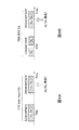
LTE、LTE−Aシステムの無線通信における複信形式(Duplex−mode)として、上りリンク(UL)と下りリンク(DL)を周波数で分割する周波数分割複信(FDD)と、上りリンクと下りリンクを時間で分割する時間分割複信(TDD)とがある(図1A参照)。TDDの場合、上りリンクと下りリンクの通信に同じ周波数領域が適用され、一つの送受信ポイントから上りリンクと下りリンクが時間で分けられて信号の送受信が行われる。 Frequency division duplex (FDD) that divides uplink (UL) and downlink (DL) by frequency as duplex format (Duplex-mode) in radio communication of LTE and LTE-A systems, and uplink and downlink And time division duplex (TDD) that divides the time by time (see FIG. 1A). In the case of TDD, the same frequency region is applied to uplink and downlink communication, and uplink and downlink are divided by time from one transmission / reception point, and signals are transmitted and received.
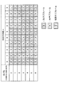
LTEシステムのTDDにおいては、上りサブフレーム(ULサブフレーム)と下りサブフレーム(DLサブフレーム)間の送信比率が異なる複数のフレーム構成(UL/DL configuration(UL/DL構成))が規定されている。具体的には、図2に示すように、UL/DL構成0〜6の7つのフレーム構成が規定されており、サブフレーム#0と#5は下りリンクに割当てられ、サブフレーム#2は上りリンクに割当てられる。各UL/DL構成において、DLからULへの切り替えを行う場合には特別サブフレームが設定される。
In the TDD of the LTE system, a plurality of frame configurations (UL / DL configuration (UL / DL configuration)) with different transmission ratios between uplink subframes (UL subframes) and downlink subframes (DL subframes) are defined. Yes. Specifically, as shown in FIG. 2, seven frame configurations of UL /
また、LTE−Aシステム(Rel.10/11)のシステム帯域は、LTEシステムのシステム帯域を一単位とする少なくとも1つのコンポーネントキャリア(CC:Component Carrier)を含んでいる。複数のコンポーネントキャリア(セル)を集めて広帯域化することをキャリアアグリゲーション(CA:Carrier Aggregation)という。 Further, the system band of the LTE-A system (Rel. 10/11) includes at least one component carrier (CC: Component Carrier) having the system band of the LTE system as a unit. Collecting a plurality of component carriers (cells) to increase the bandwidth is called carrier aggregation (CA).
Rel.10で導入されたキャリアアグリゲーション(CA)を適用する場合、TDDでは、複数のCC(セル、送受信ポイントともいう)間の干渉を回避するため、地理的に隣接する送信ポイント間では、ある1つの周波数キャリアにおいて同じUL/DL構成に限られていた。しかし、一般にDLのトラヒックとULのトラヒックは非対称である。また、DLのトラヒックとULのトラヒックの比率は一定ではなく、時間的に、あるいは、場所的に変動する。そこで、Rel.11では、トラヒックに応じてUL/DL構成の切り替えを柔軟に行うことができるように、異なるセル間で異なるUL/DL構成を適用するCA(TDD inter−band CA)がサポートされた。 Rel. In the case of applying carrier aggregation (CA) introduced in FIG. 10, in TDD, in order to avoid interference between a plurality of CCs (also referred to as cells or transmission / reception points), there is a certain one between geographically adjacent transmission points. The frequency carrier is limited to the same UL / DL configuration. However, in general, DL traffic and UL traffic are asymmetric. Also, the ratio of DL traffic to UL traffic is not constant, but varies with time or location. Therefore, Rel. 11 supports CA (TDD inter-band CA) that applies different UL / DL configurations between different cells so that UL / DL configurations can be flexibly switched according to traffic.
また、Rel.10/11におけるキャリアアグリゲーション(CA)では、複数のCC間で適用されるDuplex−modeは、同一のDuplex−modeに限られている(図1B参照)。一方で、将来の無線通信システム(例えば、Rel.12以降)では、複数CC間で異なるDuplex−mode(TDD+FDD)を適用したCAも想定される(図1C参照)。 Also, Rel. In carrier aggregation (CA) in 10/11, Duplex-mode applied between a plurality of CCs is limited to the same Duplex-mode (see FIG. 1B). On the other hand, in a future radio communication system (for example, Rel.
このような無線通信システムの利用形態の拡張に伴い、トラヒック等を考慮してUL伝送とDL伝送を柔軟に制御することがより一層望まれる。例えば、データトラフィックが下りに偏重した環境にTDDを用いる場合にスループットを最適化することが望まれる。しかし、新たな無線通信システムの利用形態において、既存のメカニズム(例えば、TDDにおける既存のUL/DL構成)を利用する場合、スループットの向上や、新たな利用形態への対応が困難になるおそれがある。 Along with the expansion of usage forms of such wireless communication systems, it is further desired to flexibly control UL transmission and DL transmission in consideration of traffic and the like. For example, it is desirable to optimize the throughput when TDD is used in an environment where data traffic is concentrated on the downlink. However, when an existing mechanism (for example, an existing UL / DL configuration in TDD) is used in a usage form of a new wireless communication system, it may be difficult to improve throughput or cope with the new usage form. is there.
本発明はかかる点に鑑みてなされたものであり、データトラフィックが下りに偏重した環境においてTDDを用いる場合に、スループットを向上すると共に様々な無線通信システムの利用形態へ対応することが可能となるユーザ端末、無線基地局及び無線通信方法を提供することを目的の一とする。 The present invention has been made in view of the above points, and when TDD is used in an environment where data traffic is concentrated on the downlink, it is possible to improve throughput and cope with various usage modes of a wireless communication system. An object is to provide a user terminal, a radio base station, and a radio communication method.
本発明のユーザ端末は、TDDを利用して通信を行うユーザ端末であって、下り時間区間(DwPTS)、ガード期間(GP)及び上り時間区間(UpPTS)で構成される特別サブフレームが所定サブフレームに設定されるUL/DL構成を利用して信号の送受信を行う送受信部と、複数の特別サブフレーム構成が定義されたテーブルに基づいて前記特別サブフレームにおける信号の送受信を制御する制御部と、を有し、前記制御部は、上位レイヤシグナリングで通知される情報に基づいて、あらかじめ設定された前記特別サブフレーム構成のDwPTS長は変更せずに、UpPTS長を拡張することを特徴とする。
The user terminal according to the present invention is a user terminal that performs communication using TDD, and a special subframe that includes a downlink time interval (DwPTS), a guard period (GP), and an uplink time interval (UpPTS) has a predetermined subframe. A transmission / reception unit that transmits / receives signals using a UL / DL configuration set in a frame, and a control unit that controls transmission / reception of signals in the special subframe based on a table in which a plurality of special subframe configurations are defined; The control unit extends the UpPTS length without changing the DwPTS length of the special subframe configuration set in advance based on information notified by higher layer signaling. The
本発明によれば、データトラフィックが下りに偏重した環境においてTDDを用いる場合に、スループットを向上すると共に様々な無線通信システムの利用形態へ対応することが可能となる。 According to the present invention, when TDD is used in an environment in which data traffic is concentrated on the downlink, it is possible to improve throughput and cope with various usage modes of a wireless communication system.
上述したように、LTE、LTE−Aシステムでは、Duplex modeとしてFDDとTDDの2つが規定されている(図1A参照)。また、TDDでは上記図2に示したUL/DL構成0〜6から選択される所定のUL/DL構成を利用して無線基地局−ユーザ端末間で通信を行う。このように、TDDでは、UL/DL構成毎にULサブフレームとDLサブフレームの送信比率が異なっており、各構成に対してそれぞれ送達確認信号(A/N)のフィードバックメカニズム(HARQメカニズム)等が規定されている。
As described above, in the LTE and LTE-A systems, FDD and TDD are defined as Duplex modes (see FIG. 1A). In TDD, communication is performed between the radio base station and the user terminal using a predetermined UL / DL configuration selected from the UL /
将来(例えば、Rel.12以降)のシステムでは、複数CC間で異なるDuplex−mode(TDD+FDD)を適用したCAも想定されている(図1C参照)。この場合、TDDを適用するセル(以下、「TDDセル」とも記す)では、既存のシステム(例えば、Rel.10/11)と同様にUL/DL構成0〜6を適用することが考えられる。しかし、TDDセルを含む複数のセル間でCAを適用する場合、既存のUL/DL構成ではスループットの最適化が困難となるおそれがある。
In a future system (for example, after Rel.12), CA that applies Duplex-mode (TDD + FDD) different among a plurality of CCs is also assumed (see FIG. 1C). In this case, in a cell to which TDD is applied (hereinafter also referred to as “TDD cell”), UL /
例えば、DLトラヒックがULトラヒックより大きい通信環境において、CAを適用する複数のセルの中から所定のセルをDL伝送用として利用する形態を想定する。この場合、DL伝送用として選択されたセルがFDDを適用するセル(以下、「FDDセル」とも記す)であれば、各サブフレームでDL伝送が可能となる。一方で、DL伝送用として選択されたセルがTDDセルである場合には、DLサブフレームの構成比率が最も高いUL/DL構成(図2のUL/DL構成5)を適用することが考えられる。
For example, in a communication environment where DL traffic is larger than UL traffic, a mode is assumed in which a predetermined cell is used for DL transmission among a plurality of cells to which CA is applied. In this case, if the cell selected for DL transmission is a cell to which FDD is applied (hereinafter also referred to as “FDD cell”), DL transmission is possible in each subframe. On the other hand, when the cell selected for DL transmission is a TDD cell, it may be possible to apply the UL / DL configuration (UL /
しかし、DLサブフレームの構成比率が最も高いUL/DL構成5を適用する場合であっても、ULサブフレームと特別サブフレームが含まれている(SF#1、SF#2)。このように、既存のUL/DL構成では少なくともULサブフレームが含まれているため、TDDセルをDL伝送用に利用する場合には、DLデータの伝送に利用できないサブフレーム(例えば、SF#2)が発生してしまう。その結果、スループットの向上を十分に達成することができない。なお、特別サブフレームは、下り時間区間(DwPTS)、ガード期間(GP)及び上り時間区間(UpPTS)で構成されるため、DwPTSを用いてDL伝送を行うことができる。
However, even when UL /
そこで、本発明者等は、TDDセルを含む複数のセルを用いてCAを行う場合に、システムの利用形態によっては既存のUL/DL構成ではスループットの最適化が図れないことに着目し、新規のUL/DL構成を利用することを検討している。具体的には、TDDセルにおいて、全てのサブフレームでDL伝送が可能となるDL伝送用のUL/DL構成(以下、「UL/DL構成7」とも記す)を新たに導入する。また、当該UL/DL構成7は、TDDセルがセカンダリセル(SCell)である場合(プライマリセル(PCell)でない場合)に好適に利用することができる。
Therefore, the present inventors paid attention to the fact that when performing CA using a plurality of cells including TDD cells, the throughput cannot be optimized with the existing UL / DL configuration depending on the system usage form. We are considering using the UL / DL configuration. Specifically, a UL / DL configuration for DL transmission (hereinafter also referred to as “UL /
ここで、プライマリセル(PCell)とは、CAを行う場合にRRC接続やハンドオーバを管理するセルであり、端末からのデータやフィードバック信号を受信するためにUL伝送も必要となるセルである。CAを行う場合、プライマリセルは上下リンクともに常に設定される。セカンダリセル(SCell)とは、CAを適用する際にプライマリセルに加えて設定する他のセルである。セカンダリセルは下りリンクだけ設定することもできるし、上下リンクを同時に設定することもできる。 Here, a primary cell (PCell) is a cell that manages RRC connection and handover when performing CA, and is a cell that also requires UL transmission to receive data and feedback signals from a terminal. When performing CA, the primary cell is always set for both the uplink and the downlink. The secondary cell (SCell) is another cell that is set in addition to the primary cell when CA is applied. A secondary cell can set only a downlink, and can also set up-and-down link simultaneously.
このように、無線通信システムの利用形態に応じてDL伝送用のUL/DL構成7を適用することにより、スループットを向上することが可能となる。なお、DL伝送用のUL/DL構成7としては、利用形態に応じて、DLサブフレームのみ設ける場合(特別サブフレーム非設定)と(図3A参照)、DLサブフレームと特別サブフレームを設ける場合が考えられる(図3B参照)。
In this way, by applying the UL /
ところで、将来の無線通信システムでは、LTEシステムを、事業者にライセンスされた周波数帯域(Licensed band)だけでなく、ライセンス不要の周波数帯域(Unlicensed band)で運用することも検討されている。ライセンス帯域(Licensed band)は、特定の事業者が独占的に使用することを許可された帯域であり、非ライセンス帯域(Unlicensed band)は特定事業者に限定せずに無線局を設置可能な帯域である。非ライセンス帯域(Unlicensed band)として、例えば、WiFiやBluetooth(登録商標)を使用可能な2.4GHz帯や5GHz帯、ミリ波レーダーを使用可能な60GHz帯等がある。 By the way, in a future wireless communication system, it is considered that the LTE system is operated not only in a frequency band (licensed band) licensed by an operator but also in a frequency band (unlicensed band) that does not require a license. A licensed band is a band that a specific operator is allowed to use exclusively, and an unlicensed band is a band in which a radio station can be installed without being limited to a specific operator. It is. Examples of the unlicensed band include a 2.4 GHz band and 5 GHz band that can use WiFi and Bluetooth (registered trademark), and a 60 GHz band that can use millimeter wave radar.
非ライセンス帯域は、ライセンス帯域と異なり特定の事業者のみが使用するわけでないため、予期しない干渉が発生する可能性がある。例えば、非ライセンス帯域において、LTEシステムと異なる無線通信システム(気象・航空レーダー、放送、防災無線、公共無線、地域無線、WiFi、Bluetooth等)が運用される(周波数を共有する)可能性がある。この場合、異なる無線通信システム間で、互いに予期しない干渉が生じるおそれがある。 Since the unlicensed band is not used only by a specific operator unlike the licensed band, unexpected interference may occur. For example, in a non-licensed band, there is a possibility that a radio communication system (meteorology / aviation radar, broadcasting, disaster prevention radio, public radio, regional radio, WiFi, Bluetooth, etc.) different from the LTE system may be operated (sharing frequencies). . In this case, unexpected interference may occur between different wireless communication systems.
異なる無線通信システム間の干渉を抑制するために、いずれかの無線通信システムを優先して動作するように制御することも考えられる。例えば、他の無線通信システムがLTEシステムに対して優先されるように規定される可能性も想定される。かかる場合、非ライセンス帯域において他の優先無線システムの運用を検出した場合、LTEシステムを利用した通信を停止することとなる。 In order to suppress interference between different wireless communication systems, it may be considered to control one of the wireless communication systems to operate with priority. For example, there is a possibility that other wireless communication systems may be defined to be prioritized over the LTE system. In this case, when operation of another priority wireless system is detected in the non-licensed band, communication using the LTE system is stopped.
また、異なるLTE事業者同士が非ライセンス帯域における同一の周波数を利用してLTEシステムを運用する可能性も考えられる。例えば、異なる事業者同士が近接する場所にLTE基地局を設置して同一周波数で運用を行う場合、互いに大きな干渉を生じるおそれがある。そのため、非ライセンス帯域を利用してLTEシステムを運用する利用形態では、上述した干渉等を考慮することが必要となる。 Also, there is a possibility that different LTE operators operate the LTE system using the same frequency in the non-licensed band. For example, when an LTE base station is installed in a place where different operators are close to each other and operated at the same frequency, there is a possibility of causing large interference with each other. Therefore, it is necessary to consider the above-described interference and the like in a usage mode in which an LTE system is operated using a non-licensed band.
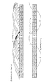
本発明者等は、ライセンス帯域(Licensed band)に加えて非ライセンス帯域(Unlicensed band)でLTEシステムを運用する場合に、上述したUL/DL構成7を、非ライセンス帯域で使用することも検討している(図4参照)。例えば、ライセンス帯域でFDDセルを運用し、非ライセンス帯域でTDDセル(UL/DL構成7)を運用し、FDDセルとTDDセル間でCAを適用する利用形態(図4B参照)が考えられる。あるいは、ライセンス帯域及び非ライセンス帯域でTDDセルを運用し、TDDセル間でCAを適用する利用形態(図4A参照)も考えられる。
The present inventors also considered using the above-mentioned UL /
ライセンス帯域では、事業者が基地局の運用により干渉を制御することができるため、制御信号や高品質が要求されるデータの通信に利用することができる。一方で、非ライセンス帯域では予期しない干渉が発生する可能性があるが、比較的広い帯域が使用可能なため、パケット等のトラフィックが大きいデータ通信(DL伝送)に好適に利用することができる。そのため、非ライセンス帯域のTDDセルでUL/DL構成7を利用してCAを行うことにより、ライセンス帯域と非ライセンス帯域の双方のメリットを生かした通信を実現することが可能となる。
In the license band, since the operator can control interference by operating the base station, it can be used for communication of control signals and data requiring high quality. On the other hand, unexpected interference may occur in the non-licensed band, but since a relatively wide band can be used, it can be suitably used for data communication (DL transmission) in which traffic such as packets is large. Therefore, by performing CA using the UL /
また、将来の無線通信システムでは、上述のようにセカンダリセル(SCell)として用いていたTDDセルを、CAを設定しない場合でも(すなわち、別途プライマリセル(PCell)による通信を前提とせずに)接続可能なセルとして運用することも考えられる。具体的には、ユーザ端末が初期接続可能なセル(Stand−alone)、又は、独自にスケジューリング可能なセル(Dual connectivity)として適用することも考えられる。なお、Stand−aloneで動作するセルは、独立して(つまりCAのセカンダリセル(SCell)でなくとも)ユーザ端末と初期接続が可能となる。また、Dual connectivityとは、それぞれ独立してスケジューリングする(スケジューラを具備する)複数のセルにユーザ端末が接続する形態を指す。 Further, in the future radio communication system, the TDD cell used as the secondary cell (SCell) as described above is connected even when CA is not set (that is, without presuming communication by a separate primary cell (PCell)). It is also possible to operate as a possible cell. Specifically, it may be applied as a cell (Stand-alone) to which a user terminal can be initially connected, or as a cell (Dual connectivity) that can be uniquely scheduled. Note that a cell that operates in a stand-alone can be initially connected to a user terminal independently (that is, not a CA secondary cell (SCell)). Also, dual connectivity refers to a form in which a user terminal is connected to a plurality of cells that are scheduled independently (provided with a scheduler).
このような利用形態では、TDDセルにおいてUL伝送を行う必要があるが、かかる場合にUL/DL構成7をどのように利用して通信を行うかが問題となる。つまり、UL/DL構成7をStand−alone又はDual connectivityで用いるためには、上りチャネルや上り参照信号のサポートが必要となる。例えば、UL/UD構成7を利用して、少なくともPRACH信号、ランダムアクセス処理におけるメッセージ3、上位レイヤ制御信号、下りHARQ−ACK(送達確認信号)、CQI(チャネル品質情報)、SR(スケジューリング要求信号)、SRS(チャネル品質測定用参照信号)等の上りリンク信号の送信を行う必要がある。
In such a use form, it is necessary to perform UL transmission in the TDD cell. In such a case, how to use the UL /
そのため、UL/DL構成7として、上りのタイミングを有する(特別サブフレームを含む)上記図3Bの構成を利用することが考えられる。しかし、既存のLTEシステム(Rel.10/11)の特別サブフレームの構成では、上り時間区間(UpPTS)を用いて上述した上りリンク信号の送信を行うことができない。以下に、既存の特別サブフレーム構成(Sp−SF Config)について図5を参照して説明する。
Therefore, as the UL /
既存のLTEシステム(Rel.10/11)では、特別サブフレーム構成(Sp−SF Config)として、通常CP(Normal CP)で10種類、拡張CP(Extended CP)で8種類が定義されている(図5A参照)。また、特別サブフレーム構成に関する情報は、プライマルセルにおいてはシステム情報(SIB1)を用いてユーザ端末に通知され、セカンダリセルにおいてはRRCシグナリングを用いてユーザ端末に通知される。 In the existing LTE system (Rel. 10/11), 10 types of normal CP (Normal CP) and 8 types of extended CP (Extended CP) are defined as special subframe configurations (Sp-SF Config) ( (See FIG. 5A). Also, information regarding the special subframe configuration is notified to the user terminal using system information (SIB1) in the primal cell, and is notified to the user terminal using RRC signaling in the secondary cell.
図5Aの表に記載された数字はOFDM(またはSC−FDMA)シンボル数を表す。既存の特別サブフレーム構成では、上り時間区間(UpPTS)が最大で2シンボルまでしか設定されない。そのため、ULサブフレームにおいてPUSCHを用いて送信するユーザデータ(PUSCH信号)やPUCCHを用いて送信する上り制御信号(PUCCH信号)等の送信は行えない。一方で、既存の特別サブフレームでは、UL伝送としてPRACH信号とSRSの送信のみサポートされている。したがって、上述したUL/DL構成7を利用する場合(図5B参照)、既存の特別サブフレーム構成では、セカンダリセル(SCell)以外の運用を想定した場合に必須となるUL信号(ユーザデータや上り制御情報等)を送信することができない。
The numbers listed in the table of FIG. 5A represent the number of OFDM (or SC-FDMA) symbols. In the existing special subframe configuration, the maximum uplink time interval (UpPTS) is set to 2 symbols at maximum. Therefore, transmission of user data (PUSCH signal) transmitted using PUSCH in the UL subframe, uplink control signal (PUCCH signal) transmitted using PUCCH, and the like cannot be performed. On the other hand, in the existing special subframe, only PRACH signal and SRS transmission are supported as UL transmission. Therefore, when the UL /
そこで、本発明者等は、UL/DL構成7のうち、特別サブフレームを含む図3Bを利用する場合であっても、PRACH信号とSRS以外のUL信号の送信が可能となるように、特別サブフレーム構成の上り時間区間(UpPTS)を拡張することを着想した。
Therefore, the present inventors have made a special arrangement so that UL signals other than the PRACH signal and the SRS can be transmitted even when using FIG. 3B including the special subframe in the UL /
以下に、本実施の形態にかかる無線通信方法について図面を参照して詳細に説明する。なお、本実施の形態では、図3BのUL/DL構成7を利用するTDDセルは、ライセンス領域又は非ライセンス領域で用いることができる。
The radio communication method according to the present embodiment will be described in detail below with reference to the drawings. In the present embodiment, the TDD cell using the UL /
(第1の態様)
第1の態様では、TDDセルの特別サブフレーム構成(Sp−SF Config)として、上り時間区間(UpPTS)を既存より拡張した特別サブフレーム構成を導入する場合について説明する。
(First aspect)
A 1st aspect demonstrates the case where the special sub-frame structure which expanded the upstream time interval (UpPTS) from the existing is introduced as a special sub-frame structure (Sp-SF Config) of a TDD cell.
図6は、本実施の形態に係る特別サブフレーム構成の一例を示している。図6では、特別サブフレーム構成として、既存の特別サブフレーム構成0〜9に加えて、新たにUpPTSを拡張した特別サブフレーム構成10(Sp−SF Config10)を定義したテーブルを示している。新たに追加する特別サブフレーム構成10としては、UpPTSを既存より拡張した内容(少なくともUpPTSが3シンボル以上)とする。以下、このようなUpPTSを拡張UpPTS(Extended UpPTS)と呼ぶ。
FIG. 6 shows an example of a special subframe configuration according to the present embodiment. FIG. 6 shows a table defining a special subframe configuration 10 (Sp-SF Config 10) in which UpPTS is newly expanded in addition to the existing
図6では、特別サブフレーム構成10として、DwPTSを「3」、GPを「2」、UpPTSを「9」とする場合を示している。つまり、UpPTSのシンボル数を既存の1又は2から9まで増やして特別サブフレームにおけるUL送信容量を増大する。
FIG. 6 shows a case where the
これにより、ULサブフレームが設定されないUL/DL構成7を利用する場合であっても、特別サブフレームを用いて上り制御情報(UCI)、上位レイヤ制御信号、ULデータ(ユーザデータ)の送信も可能となる。その結果、通信システムの利用形態がStand−alone及び/又はDual connectivityであっても、UL/DL構成7を好適に利用することができる。
As a result, even when the UL /
なお、新たに追加する特別サブフレーム構成は1種類に限られない。UpPTSを3シンボル以上に増やした特別サブフレーム構成を複数定義してもよい。また、拡張UpPTSとしては、少なくとも3シンボル以上であればよいが、好ましくは4シンボル以上、さらに好ましくは5シンボル以上とする。また、4シンボル以上とする場合には、特別サブフレームの第10シンボルにPUSCH用のDMRSを設定することが好ましい。また、新規に導入する特別サブフレーム構成10は、UL/DL構成7の場合にのみ適用する構成としてもよい。
The newly added special subframe configuration is not limited to one type. A plurality of special subframe configurations in which UpPTS is increased to 3 symbols or more may be defined. The extended UpPTS may be at least 3 symbols or more, preferably 4 symbols or more, and more preferably 5 symbols or more. In the case of 4 symbols or more, it is preferable to set PUSCH DMRS in the 10th symbol of the special subframe. In addition, the
さらに、UpPTSを拡張して定義する際に、特別サブフレームのGP長をセル半径に応じて設定することができる。既存の特別サブフレーム構成では、GP長(GPのシンボル数)として、通常CPにおいて10/9/6/4/3/2/1が存在し、拡張CPにおいて8/7/5/3/2/1が存在している。 Furthermore, when the UpPTS is extended and defined, the GP length of the special subframe can be set according to the cell radius. In the existing special subframe configuration, the GP length (number of GP symbols) is 10/9/6/4/3/2/1 in the normal CP, and 8/7/5/3/2 in the extended CP. / 1 exists.
そこで、既存の特別サブフレーム構成において、GP長は変更せずにUpPTSのシンボル数を拡張してもよい。例えば、既存の特別サブフレーム構成0〜9に対して、GP長を変更せずに、DwPTSのシンボル数を所定値(例えば、3シンボル)に固定し、残りのシンボルをUpPTSに割当てることができる(図7参照)。図7に示す場合、特別サブフレーム構成0a〜9aから得られるUpPTS長は、通常CPにおいて10/9/8/7/5/2/1、拡張CPにおいて8/7/6/4/2/1となる。
Therefore, in the existing special subframe configuration, the number of UpPTS symbols may be expanded without changing the GP length. For example, for the existing
なお、図7では、DwPTSのシンボル数を3シンボルに固定する場合を示したが、DwPTSのシンボル数はこれに限られない。3シンボル以外の固定値としてもよいし、各特別サブフレーム構成で異なるシンボル数としてもよい。このように、GP長を既存の特別サブフレーム構成と同じ値に設定する(既存のGP長を保持する)ことにより、セル半径を変更することなく特別サブフレームを利用してPUSCH信号等の送信をサポートすることができる。ただし、TDDにおいては、特別サブフレームの先頭から第3シンボル目で同期信号が送信されること、下り物理制御チャネル(PDCCH)の最大シンボル数が3であることを考慮すれば、DwPTSのシンボル数は3以上とすることが好ましい。このようにしておけば、既存の特別サブフレーム構成しか認識できない旧来のユーザ端末(レガシーUE)が同期信号を受信でき、UL/DL構成7のTDDセルに接続できるようになる。また、特別サブフレームの下り物理制御チャネル(PDCCH)領域を確保できることから、当該特別サブフレームにおいて、下りの物理レイヤ制御をも実現することができる。
Although FIG. 7 shows the case where the number of DwPTS symbols is fixed to three, the number of DwPTS symbols is not limited to this. A fixed value other than 3 symbols may be used, or the number of symbols may be different for each special subframe configuration. In this way, by setting the GP length to the same value as the existing special subframe configuration (holding the existing GP length), it is possible to transmit a PUSCH signal or the like using the special subframe without changing the cell radius. Can support. However, in TDD, considering that the synchronization signal is transmitted in the third symbol from the head of the special subframe and that the maximum number of symbols of the downlink physical control channel (PDCCH) is 3, the number of DwPTS symbols Is preferably 3 or more. In this way, an old user terminal (legacy UE) that can recognize only the existing special subframe configuration can receive the synchronization signal, and can connect to the UL /
なお、拡張UpPTS(Extended UpPTS)を含む特別サブフレームでは、DwPTSとGP部分の無線リソースはUL送信に利用できない(図8参照)。このため、拡張UpPTSを含む特別サブフレームでは、通常のULサブフレームと比較して(DwPTS+GP)/14だけレートが低下する。したがって、無線基地局やユーザ端末は、レートの低下を考慮して、特別サブフレームを用いた上りリンク信号の送信を制御することが好ましい。レートを低下させる方法としては、いったん通常の上りサブフレーム分のリソースがあるものと想定してデータを生成し、DwPTSとGP部分にマッピングされるデータを間引く方法(パンクチャ)、あらかじめExtended UpPTSに対応する(すなわち、DwPTSとGP部分にデータをマッピングできないものと想定して)少ないデータ量で信号を生成し、Extended UpPTSにマッピングする方法(レートマッチング)が考えられる。パンクチャは、情報要素の欠落を招くため誤り訂正符号化や自動再送要求などが設定されていることが必須となるが、Extended UpPTS長に関わらず1つ(または少数)のレートでデータを生成すればよいため、システム構成の簡易化を実現できる。反対にレートマッチングは、Extended UpPTS長に応じてレートを変えなければならず、システム構成が複雑になる可能性があるが、情報要素の欠落を招かないため信頼性のより高い通信を実現可能である。 In the special subframe including the extended UpPTS (Extended UpPTS), the radio resources of the DwPTS and the GP part cannot be used for UL transmission (see FIG. 8). For this reason, in the special subframe including the extended UpPTS, the rate is reduced by (DwPTS + GP) / 14 as compared with the normal UL subframe. Therefore, it is preferable that the radio base station and the user terminal control the transmission of the uplink signal using the special subframe in consideration of the rate decrease. As a method of reducing the rate, it is assumed that there is a normal uplink subframe resource once, data is generated, and the data mapped to the DwPTS and the GP part is punctured (extended UpPTS in advance) A method (rate matching) in which a signal is generated with a small amount of data and mapped to Extended UpPTS (assuming that data cannot be mapped to DwPTS and GP) can be considered. Puncturing causes missing information elements, so it is essential that error correction coding, automatic retransmission request, etc. are set. However, data is generated at one (or a small number) rate regardless of the Extended UpPTS length. Therefore, the system configuration can be simplified. On the other hand, in rate matching, the rate must be changed according to the Extended UpPTS length, which may complicate the system configuration. However, since it does not cause loss of information elements, more reliable communication can be realized. is there.
また、上記図3Bに示すUL/DL構成7では、1無線フレーム(10ms)に1つの特別サブフレームを設定する構成を示したが、本実施の形態はこれに限られない。例えば、複数の無線フレームに一つ又は複数の特別サブフレームを挿入する構成としてもよい(図9参照)。図9Aは、2フレーム(10ms×2)に1回だけUpPTSを拡張した特別サブフレームを設定する場合を示している。また、図9Bは、4フレーム(10ms×4)に1回だけUpPTSを拡張した特別サブフレームを設定する場合を示している。
In the UL /
あるいは、複数の無線フレームにおいて、既存の特別サブフレームと、UpPTSを拡張した特別サブフレームとをそれぞれ挿入してもよい。この際、既存の特別サブフレームと、UpPTSを拡張した特別サブフレームをそれぞれ異なるタイミングや周期で挿入することができる(図10参照)。図10Aは、2フレーム(10ms×2)において、1フレーム目に既存の特別サブフレーム(ノーマルUpPTS)を設定し、2フレーム目にUpPTSを拡張した特別サブフレームを設定する場合を示している。図10Bは、4フレーム(10ms×4)において、1フレーム目〜3フレーム目に既存の特別サブフレームを設定し、4フレーム目にUpPTSを拡張した特別サブフレームを設定する場合を示している。 Alternatively, in a plurality of radio frames, an existing special subframe and a special subframe obtained by extending UpPTS may be inserted. At this time, an existing special subframe and a special subframe obtained by extending UpPTS can be inserted at different timings and periods (see FIG. 10). FIG. 10A shows a case where, in two frames (10 ms × 2), an existing special subframe (normal UpPTS) is set in the first frame, and a special subframe in which UpPTS is expanded is set in the second frame. FIG. 10B shows a case where, in 4 frames (10 ms × 4), an existing special subframe is set in the first to third frames, and a special subframe in which UpPTS is expanded is set in the fourth frame.
上記図9Bに示すように、複数無線フレームに1つだけ拡張UpPTSを含む特別サブフレームを挿入する場合、特別サブフレームの時間位置を適宜設定する構成とすることができる。例えば、特別サブフレームをあらかじめ決められた位置に設定する。あるいは、報知情報等のセル固有(Cell−specific)のシグナリングを用いてユーザ端末に特別サブフレームの時間位置を通知してもよい。あるいは、RRCシグナリングやL1/L2制御信号等のユーザ端末固有(UE−specific)のシグナリングを用いてユーザ端末に特別サブフレームの時間位置を通知してもよい。あるいは、同期情報から得たサブフレーム番号に基づく位置に特別サブフレームを設定する構成としてもよい。あるいは、これらの組み合わせを用いてユーザ端末に通知することができる。 As shown in FIG. 9B above, when a special subframe including only one extended UpPTS is inserted into a plurality of radio frames, the time position of the special subframe can be set as appropriate. For example, the special subframe is set at a predetermined position. Alternatively, the time position of the special subframe may be notified to the user terminal using cell-specific signaling such as broadcast information. Alternatively, the user terminal may be notified of the time position of the special subframe using user terminal specific (UE-specific) signaling such as RRC signaling or an L1 / L2 control signal. Alternatively, a special subframe may be set at a position based on the subframe number obtained from the synchronization information. Alternatively, the user terminal can be notified using these combinations.
このように、特別サブフレームの時間位置を適宜設定することにより、ULトラフィックとDLトラフィックの比率に応じて、ULリソース量を柔軟に制御することができる。また、上記図10Bに示すように、長い周期でUpPTSを拡張した特別サブフレームを設定する場合においても同様に特別サブフレームの時間位置を適宜設定することができる。 Thus, by appropriately setting the time position of the special subframe, the UL resource amount can be flexibly controlled according to the ratio of UL traffic and DL traffic. In addition, as shown in FIG. 10B above, when setting a special subframe in which UpPTS is extended with a long cycle, the time position of the special subframe can be set as appropriate.
(第2の態様)
第2の態様では、所定の特別サブフレーム構成を利用するユーザ端末が、下りリンクで通知される情報に基づいて、TDDセルの特別サブフレーム構成を変更する場合について説明する。具体的には、下りリンクで通知される特別サブフレーム構成の変更要求信号に基づいて、特別サブフレーム構成のGP及びUpPTSの長さを変更する場合について図11を参照して説明する。
(Second aspect)
In the second mode, a case will be described in which a user terminal that uses a predetermined special subframe configuration changes the special subframe configuration of the TDD cell based on information notified in the downlink. Specifically, a case of changing the lengths of GP and UpPTS having a special subframe configuration based on a special subframe configuration change request signal notified in the downlink will be described with reference to FIG.
図11Aは、無線基地局から所定の指示(特別サブフレーム構成の変更要求信号)がない場合に、ユーザ端末が既存の特別サブフレーム構成を利用する場合を示している。つまり、ユーザ端末は、無線基地局から所定の指示(特別サブフレーム構成の変更要求信号)がない限り、レガシー端末(Rel.8−11UE)と同様に既存の特別サブフレーム構成を用いる。この場合、ユーザ端末は、報知情報又はRRCシグナリング等であらかじめ設定された特別サブフレーム構成であると想定して動作する。図11Aでは、特別サブフレーム構成0(DwPTS:GP:UpPTS=3:10:1)を利用する場合を示している。 FIG. 11A shows a case where the user terminal uses an existing special subframe configuration when there is no predetermined instruction (special subframe configuration change request signal) from the radio base station. That is, the user terminal uses the existing special subframe configuration in the same manner as the legacy terminal (Rel. 8-11UE) unless there is a predetermined instruction (special subframe configuration change request signal) from the radio base station. In this case, the user terminal operates assuming that it has a special subframe configuration set in advance by broadcast information or RRC signaling. FIG. 11A shows a case where special subframe configuration 0 (DwPTS: GP: UpPTS = 3: 10: 1) is used.
図11Bは、特別サブフレーム構成の変更要求信号を受信したユーザ端末が、GP長及びUpPTS長を変更する場合を示している。具体的には、UpPTS長を3シンボル以上に拡張し、且つUpPTSの拡張シンボル数だけGPのシンボル数を減らすように制御する。特別サブフレーム構成の変更要求信号は、下り制御信号(例えば、ULグラント)を用いて無線基地局からユーザ端末に通知することができる。 FIG. 11B illustrates a case where the user terminal that has received the special subframe configuration change request signal changes the GP length and the UpPTS length. Specifically, control is performed so that the UpPTS length is extended to 3 symbols or more and the number of GP symbols is reduced by the number of UpPTS extended symbols. The special subframe configuration change request signal can be notified from the radio base station to the user terminal using a downlink control signal (for example, UL grant).
図11Bでは、特別サブフレーム構成の変更要求信号に応じて、特別サブフレーム構成をDwPTS:GP:UpPTS=3:2:9に変更する場合を示している。つまり、DwPTS長は変更せずに、UpPTS長とGP長を切り替えて制御する。 FIG. 11B shows a case where the special subframe configuration is changed to DwPTS: GP: UpPTS = 3: 2: 9 in response to the special subframe configuration change request signal. That is, the UpPTS length and the GP length are switched and controlled without changing the DwPTS length.
拡張するUpPTS長に関する情報は、あらかじめMIB、SIB等を有する報知信号やRRCシグナリング等の上位レイヤシグナリングを用いてユーザ端末に通知することができる。ユーザ端末は、物理レイヤの制御信号(例えば、ULグラント等)で特別サブフレーム構成の変更指示を受けた場合、所定タイミング(例えば、4ms後)に設定される特別サブフレームにおいてUpPTSを拡張する。 Information on the UpPTS length to be extended can be notified to the user terminal by using a broadcast signal having MIB, SIB or the like in advance or higher layer signaling such as RRC signaling. When the user terminal receives an instruction to change the special subframe configuration with a physical layer control signal (for example, UL grant), the user terminal extends UpPTS in a special subframe set at a predetermined timing (for example, 4 ms later).
また、タイミングアドバンス値(TA値)及び/又はULグラントで指示される変調符号化情報(MCS)等に基づいてUpPTS長を制御してもよい。TA値はセル内のユーザ端末間で上り送信タイミングをずらすために指示されるシグナリングであり、基地局での受信タイミングをそろえるために設定される。基地局が端末に指示するTA値は、一般的にセル端に位置するユーザ端末ほど大きな値となる。TA値が大きいほど、ユーザ端末はUpPTSの送信タイミングを早めて送信するため、セル端に位置するユーザ端末ほど、大きなGP長が必要となるが、セル中央に位置するユーザ端末ではGP長は短くて良い。このことを利用し、TA値が小さい、すなわちセル中央に位置するユーザ端末では拡張するUpPTS長を長く設定する。反対に、セル端に位置するユーザ端末では大きなGP長が必要なので、拡張するUpPTS長を短く設定する(図12参照)。このようにすることで、ユーザ端末の場所に応じて必要なGP長を確保しつつ、適切に拡張するUpPTS長を変えることができる。また、一般にセル中央に位置するユーザ端末ほど品質が良く、高速通信に好適であるが、この方法であればセル中央に位置するユーザ端末ほどUpPTS長を長く設定できるため、上りフィードバックの情報量を増やしたり、上りデータレートを向上することができるので、さらに高速通信を行いやすくすることができる。 Further, the UpPTS length may be controlled based on the timing advance value (TA value) and / or modulation coding information (MCS) indicated by the UL grant. The TA value is signaling instructed to shift the uplink transmission timing between user terminals in the cell, and is set to align the reception timing at the base station. The TA value instructed to the terminal by the base station generally becomes larger as the user terminal is located at the cell edge. As the TA value increases, the user terminal transmits the UpPTS at an earlier transmission timing. Therefore, the user terminal located at the cell edge needs a larger GP length, but the user terminal located at the center of the cell has a shorter GP length. Good. Utilizing this, the user terminal located in the center of the cell having a small TA value, that is, sets a long UpPTS length to be extended. On the other hand, since the user terminal located at the cell edge needs a large GP length, the UpPTS length to be expanded is set short (see FIG. 12). By doing so, it is possible to change the UpPTS length to be appropriately expanded while ensuring the necessary GP length according to the location of the user terminal. In general, the user terminal located in the center of the cell has better quality and is suitable for high-speed communication. However, if this method is used, the user terminal located in the center of the cell can be set to have a longer UpPTS length. Since it can be increased or the uplink data rate can be improved, it is possible to facilitate high-speed communication.
あるいは、複数のMCSの値に対してそれぞれ拡張するUpPTS長をあらかじめ設定しておき、各ユーザ端末のMCSに応じて特別サブフレーム構成を制御することができる。MCSはユーザ端末の通信品質や状態に基づき複数の中から選択されるが、一般的に、セル端に位置するユーザ端末では、データレートを下げて品質確保を容易にするため小さなMCSが設定され、セル中央に位置するユーザ端末では、高速通信を行うために大きなMCSが設定される。前述のように、セル端であるほど長いGP長が必要となることから、MCSが小さいほど拡張するUpPTS長を短く設定し、MCSが大きいほど拡張するUpPTS長を長く設定する(図12参照)。このようにすることで、ユーザ端末の場所に応じて必要なGP長を確保しつつ、適切に拡張するUpPTS長を変えることができる。また、一般にセル中央に位置するユーザ端末ほど品質が良く、高速通信に好適であるが、この方法であればセル中央に位置するユーザ端末ほどUpPTS長を長く設定できるため、上りフィードバックの情報量を増やしたり、上りデータレートを向上することができるので、さらに高速通信を行いやすくすることができる。 Alternatively, the UpPTS length to be extended for each of a plurality of MCS values is set in advance, and the special subframe configuration can be controlled according to the MCS of each user terminal. The MCS is selected from a plurality based on the communication quality and state of the user terminal. In general, a small MCS is set in a user terminal located at the cell edge in order to reduce the data rate and facilitate quality assurance. In the user terminal located in the center of the cell, a large MCS is set for high-speed communication. As described above, since the longer GP length is required at the cell edge, the UpPTS length to be expanded is set shorter as the MCS is smaller, and the UpPTS length to be expanded is set longer as the MCS is larger (see FIG. 12). . By doing so, it is possible to change the UpPTS length to be appropriately expanded while ensuring the necessary GP length according to the location of the user terminal. In general, the user terminal located in the center of the cell has better quality and is suitable for high-speed communication. However, if this method is used, the user terminal located in the center of the cell can be set to have a longer UpPTS length. Since it can be increased or the uplink data rate can be improved, it is possible to facilitate high-speed communication.
このように、無線基地局からの指示に応じてGP及びUpPTSの長さを制御することにより、ユーザ端末は変更要求信号を受信しない限り既存の特別サブフレームとみなして動作するため、既存端末との共存が容易となる。例えば、既存端末が存在する場合にはユーザ端末に変更要求信号を送信せず、既存端末が存在しない場合に変更要求信号を送信することができる。これにより、既存端末の有無に応じてUpPTSの拡張を制御することも可能となる。 Thus, by controlling the lengths of GP and UpPTS in accordance with an instruction from the radio base station, the user terminal operates as an existing special subframe unless receiving a change request signal. Coexistence becomes easy. For example, when there is an existing terminal, the change request signal is not transmitted to the user terminal, and when there is no existing terminal, the change request signal can be transmitted. This makes it possible to control the extension of UpPTS according to the presence or absence of an existing terminal.
また、無線基地局からの指示に応じて、GP及びUpPTSの長さを制御することにより、スケジューラがダイナミック(動的)にULリソースの割当てを制御することができる。これにより、干渉やユーザ端末間のタイミング差等を考慮して、ULリソースの割当て可否を決定することができる。 Further, by controlling the lengths of GP and UpPTS in accordance with an instruction from the radio base station, the scheduler can dynamically control the allocation of UL resources. As a result, it is possible to determine whether or not UL resources can be allocated in consideration of interference, timing differences between user terminals, and the like.
なお、ダイナミック(動的)かつユーザ端末ごとにUpPTS長が変わる運用では、ユーザ端末と基地局との間でUpPTS長の長さに認識ずれが生じる場合がある。具体的には、基地局がユーザ端末に対して拡張UpPTSを8シンボルから10シンボルに変更を指示したが、ユーザ端末が指示情報を正しく受信できなかった場合、基地局はユーザ端末が10シンボルでUpPTSを送信したと想定するが、ユーザ端末は8シンボルでUpPTSを送信する可能性がある。レートマッチングを適用している場合、このような場合に備えて、基地局はユーザ端末が10シンボルで送信した場合と8シンボルで送信した場合の両方のマッピングに基づいて復調・復号を行う必要がある。一方で、パンクチャを適用した場合、情報要素の欠落有無は異なるものの、ユーザ端末は8シンボルの場合でも10シンボルの場合でも同じマッピングを適用しているため、ユーザ端末がいずれのシンボル数でUpPTSを送信したとしても、1度の復調・復号で情報を取り出せる可能性が高い。このように、パンクチャを用いている場合はより処理負担や電力消費を少なくできる。 Note that in an operation that is dynamic and the UpPTS length changes for each user terminal, there may be a recognition gap in the length of the UpPTS length between the user terminal and the base station. Specifically, if the base station instructs the user terminal to change the extended UpPTS from 8 symbols to 10 symbols, but the user terminal fails to correctly receive the instruction information, the base station uses 10 symbols for the user terminal. Although it is assumed that UpPTS is transmitted, the user terminal may transmit UpPTS with 8 symbols. When rate matching is applied, in order to prepare for such a case, the base station needs to perform demodulation / decoding based on the mapping of both when the user terminal transmits 10 symbols and when it transmits 8 symbols. is there. On the other hand, when puncturing is applied, the presence or absence of information elements is different, but the user terminal applies the same mapping regardless of whether it is 8 symbols or 10 symbols. Even if it is transmitted, there is a high possibility that information can be extracted by one demodulation and decoding. Thus, when puncturing is used, the processing load and power consumption can be reduced.
(第3の態様)
第3の態様では、所定の特別サブフレーム構成を利用するユーザ端末が、下りリンクで通知される特別サブフレーム構成の変更要求信号に基づいて、特別サブフレーム構成のGP及びUpPTSの長さを変更する場合について図13を参照して説明する。
(Third aspect)
In the third aspect, a user terminal using a predetermined special subframe configuration changes the length of GP and UpPTS of the special subframe configuration based on a change request signal of the special subframe configuration notified in the downlink This will be described with reference to FIG.
図13Aは、無線基地局から特別サブフレーム構成の変更要求指示がない場合に、ユーザ端末が既存の特別サブフレーム構成を利用する場合を示している。つまり、ユーザ端末は、特別サブフレーム構成の変更要求信号を受信しない限り、レガシー端末(Rel.8−11UE)と同様に既存の特別サブフレーム構成を用いる。図13Aでは、特別サブフレーム構成7(DwPTS:GP:UpPTS=10:2:2)を利用する場合を示している。 FIG. 13A illustrates a case where the user terminal uses an existing special subframe configuration when there is no special subframe configuration change request instruction from the radio base station. In other words, the user terminal uses the existing special subframe configuration in the same manner as the legacy terminal (Rel. 8-11UE) unless it receives the special subframe configuration change request signal. FIG. 13A shows a case where special subframe configuration 7 (DwPTS: GP: UpPTS = 10: 2: 2) is used.
図13Bは、特別サブフレーム構成の変更要求信号を受信したユーザ端末が、DwPTS長及びUpPTS長を変更する場合を示している。具体的には、UpPTS長を3シンボル以上に拡張し、且つUsPTSの拡張シンボル数だけDwPTSのシンボル数を減らすように制御する。特別サブフレーム構成の変更要求信号は、下り制御信号(例えば、ULグラント)を用いて無線基地局からユーザ端末に通知することができる。 FIG. 13B illustrates a case where the user terminal that has received the special subframe configuration change request signal changes the DwPTS length and the UpPTS length. Specifically, the control is performed so that the UpPTS length is extended to 3 symbols or more and the number of DwPTS symbols is reduced by the number of UsPTS extended symbols. The special subframe configuration change request signal can be notified from the radio base station to the user terminal using a downlink control signal (for example, UL grant).
図13Bでは、特別サブフレーム構成の変更要求信号に応じて、特別サブフレーム構成をDwPTS:GP:UpPTS=3:2:9に変更する場合を示している。つまり、GP長は変更せずに、UpPTS長とDwPTS長を切り替えて制御する。 FIG. 13B shows a case where the special subframe configuration is changed to DwPTS: GP: UpPTS = 3: 2: 9 in response to the special subframe configuration change request signal. That is, without changing the GP length, the UpPTS length and the DwPTS length are switched and controlled.
拡張するUpPTS長に関する情報は、上記第2の態様と同様にあらかじめMIB、SIB等を有する報知信号やRRCシグナリング等の上位レイヤシグナリングを用いてユーザ端末に通知することができる。ユーザ端末は、物理レイヤの制御信号(例えば、ULグラント等)で特別サブフレーム構成の変更指示を受けた場合、所定タイミング(例えば、4ms後)に設定される特別サブフレームにおいてUpPTSを拡張する。 The information on the UpPTS length to be extended can be notified to the user terminal by using a broadcast signal having MIB, SIB or the like in advance and higher layer signaling such as RRC signaling as in the second aspect. When the user terminal receives an instruction to change the special subframe configuration with a physical layer control signal (for example, UL grant), the user terminal extends UpPTS in a special subframe set at a predetermined timing (for example, 4 ms later).
このように、無線基地局からの指示に応じて、特別サブフレームのDwPTS及びUpPTSの長さを切り替えて制御することにより、DLトラフィックとUPトラフィックに応じて柔軟にリソースを制御することができる。例えば、ユーザ端末は、変更要求信号の受信有無に応じて、PDSCHを受信する(UpPTSが短くULデータ送信できない)サブフレームと、UpPTSが長くULデータを送信できるサブフレームをダイナミック(動的)に切り替えて制御する。 As described above, the resources can be flexibly controlled according to the DL traffic and the UP traffic by switching and controlling the lengths of the DwPTS and UpPTS of the special subframe according to the instruction from the radio base station. For example, the user terminal dynamically changes a subframe that receives PDSCH (UpPTS is short and cannot transmit UL data) and a subframe that has a long UpPTS and can transmit UL data according to whether or not a change request signal is received. Switch and control.
また、GP長を固定して、UpPTSとDwPTSの長さを切り替えて制御することにより、既存セルに適用する場合であっても当該GPを用いて干渉を抑制することが可能となる。つまり、特別サブフレーム構成のGP長を考慮して設定された既存セルにおいて、UpPTSを拡張した特別サブフレームを適用する場合であっても干渉の発生等を抑制することができる。 Moreover, by fixing the GP length and controlling the lengths of UpPTS and DwPTS by switching, interference can be suppressed using the GP even when applied to an existing cell. That is, in an existing cell set in consideration of the GP length of the special subframe configuration, occurrence of interference or the like can be suppressed even when a special subframe obtained by extending UpPTS is applied.
(第4の態様)
第4の態様では、UpPTS長を拡張した特別サブフレームを用いて送信する上りリンク信号に関連する動作のタイミング制御について説明する。
(Fourth aspect)
In the fourth aspect, timing control of an operation related to an uplink signal transmitted using a special subframe in which the UpPTS length is extended will be described.
既存のLTEでは、特別サブフレームを用いたPUCCH信号やPUSCH信号の送信をサポートしておらず、特別サブフレームでは、PDCCH信号やPDSCH信号の送信(DL割当て)のみサポートされていた。このため、ユーザ端末は、特別サブフレームをDLサブフレームとみなして動作していた。つまり、既存のLTEでは、特別サブフレームで送信する上りリンク信号に関連する動作(例えば、DL HARQフィードバック、ULグラントに対するPUSCH送信、PUSCHに対するPHICH受信(UL HARQ))のタイミング制御について規定されていない。 Existing LTE does not support transmission of PUCCH signals and PUSCH signals using special subframes, and only transmission of PDCCH signals and PDSCH signals (DL allocation) is supported in special subframes. For this reason, the user terminal operates by regarding the special subframe as a DL subframe. That is, in the existing LTE, timing control of operations related to uplink signals transmitted in a special subframe (for example, DL HARQ feedback, PUSCH transmission for UL grant, PHICH reception for PUSCH (UL HARQ)) is not stipulated. .
特別サブフレームで送信する上りリンク信号に関連する動作のタイミングが正しく設定されていない場合、特別サブフレームにおける動的なスケジューリングやHARQが適用できず、上りリンク通信を適切に行うことが困難となる。 If the timing of the operation related to the uplink signal transmitted in the special subframe is not set correctly, dynamic scheduling and HARQ in the special subframe cannot be applied, and it is difficult to appropriately perform uplink communication. .
本発明者等は、既存の特別サブフレームをDLサブフレームとみなした場合、既存のUL/DL構成5のULとDLの比率がDL:UL=9:1である点に着目した(図14参照)。図14は、既存のUL/DL構成5のULサブフレームで送信する上りリンク信号に関連する動作(DL HARQフィードバック、ULグラントに対するPUSCH送信、PUSCHに対するPHICH受信(UL HARQ))のタイミングについて示している。
The present inventors paid attention to the point that when the existing special subframe is regarded as a DL subframe, the ratio of UL to DL in the existing UL /
また、本発明者等は、UpPTS長を拡張した特別サブフレームをULサブフレームとみなせる点に着目した。この場合、拡張UpPTSを含む特別サブフレーム構成のULとDLの比率がDL:UL=9:1とみなせる。そこで、UpPTS長を拡張した特別サブフレームを用いて上りリンク信号を送信する場合に、既存のUL/DL構成5のメカニズムを利用することを着想した。
In addition, the present inventors have focused on the point that a special subframe with an extended UpPTS length can be regarded as a UL subframe. In this case, the ratio of UL to DL in the special subframe configuration including the extended UpPTS can be regarded as DL: UL = 9: 1. Therefore, the idea of using the mechanism of the existing UL /
図15に、本実施の形態に係るUL/DL構成7の特別サブフレーム(ULサブフレーム)で送信する上りリンク信号に関連する動作(DL HARQフィードバック、ULグラントに対するPUSCH送信、PUSCHに対するPHICH受信(UL HARQ))のタイミング制御を示す。図15では、既存のUL/DL構成5のDL/UL HARQタイミングとULスケジューリングタイミングと同じメカニズムを利用している。但し、図15では、既存のUL/DL構成5と比較して、各動作のタイミングに対応するサブフレーム番号を全て−1だけシフトする。
FIG. 15 shows operations related to uplink signals transmitted in a special subframe (UL subframe) of UL /
このように、本実施の形態では、UL/DL構成7を適用する場合に、UpPTS長を拡張した特別サブフレームで送信する上りリンク信号に関連する動作タイミングを、既存のUL/DL構成5のメカニズムを利用して制御する。これにより、新たなDL/UL構成7においても、Rel.8で規定されたHARQタイミングやULスケジューリングタイミングに所定のオフセットを適用する(サブフレームを−1とする)だけであるため、既存のユーザ端末にも容易に適用することが可能となる。
As described above, in the present embodiment, when UL /
(無線通信システムの構成)
以下、本実施の形態に係る無線通信システムの一例について、詳細に説明する。
(Configuration of wireless communication system)
Hereinafter, an example of the radio communication system according to the present embodiment will be described in detail.
図16は、本実施の形態に係る無線通信システムの概略構成図である。なお、図16に示す無線通信システムは、例えば、LTEシステム或いは、SUPER 3Gが包含されるシステムである。この無線通信システムでは、LTEシステムのシステム帯域幅を1単位とする複数の基本周波数ブロック(コンポーネントキャリア)を一体としたキャリアアグリゲーション(CA)を適用することができる。また、この無線通信システムは、IMT−Advancedと呼ばれても良いし、4G、FRA(Future Radio Access)と呼ばれても良い。 FIG. 16 is a schematic configuration diagram of a radio communication system according to the present embodiment. Note that the radio communication system shown in FIG. 16 is a system that includes, for example, the LTE system or SUPER 3G. In this radio communication system, carrier aggregation (CA) in which a plurality of basic frequency blocks (component carriers) having the system bandwidth of the LTE system as one unit can be applied. Further, this radio communication system may be called IMT-Advanced, or may be called 4G, FRA (Future Radio Access).
図16に示す無線通信システム1は、マクロセルC1を形成する無線基地局11と、マクロセルC1内に配置され、マクロセルC1よりも狭いスモールセルC2を形成する無線基地局12a及び12bとを備えている。また、マクロセルC1及び各スモールセルC2には、ユーザ端末20が配置されている。ユーザ端末20は、無線基地局11及び無線基地局12の双方に接続することができる。また、無線基地局11と無線基地局12間で基地局内CA(Intra−eNB CA)、又は基地局間CA(Inter−eNB CA)が適用される。また、無線基地局11と無線基地局12間のCAとしては、TDD−TDD CA又はTDD−FDD CA等を適用することができる。
The
ユーザ端末20と無線基地局11との間は、相対的に低い周波数帯域(例えば、2GHz)で帯域幅が狭いキャリア(既存キャリア、Legacy carrier等と呼ばれる)を用いて通信を行うことができる。一方、ユーザ端末20と無線基地局12との間は、相対的に高い周波数帯域(例えば、3.5GHz等)で帯域幅が広いキャリアが用いられてもよいし、無線基地局11との間と同じキャリアが用いられてもよい。ユーザ端末20と無線基地局12間のキャリアタイプとしてニューキャリアタイプ(NCT)を利用してもよい。無線基地局11と無線基地局12(又は、無線基地局12間)は、有線接続(Optical fiber、X2インターフェース等)又は無線接続されている。
Communication between the
無線基地局11及び各無線基地局12は、それぞれ上位局装置30に接続され、上位局装置30を介してコアネットワーク40に接続される。なお、上位局装置30には、例えば、アクセスゲートウェイ装置、無線ネットワークコントローラ(RNC)、モビリティマネジメントエンティティ(MME)等が含まれるが、これに限定されるものではない。また、各無線基地局12は、無線基地局11を介して上位局装置に接続されてもよい。
The
なお、無線基地局11は、相対的に広いカバレッジを有する無線基地局であり、eNodeB、マクロ基地局、送受信ポイントなどと呼ばれてもよい。また、無線基地局12は、局所的なカバレッジを有する無線基地局であり、スモール基地局、ピコ基地局、フェムト基地局、Home eNodeB、マイクロ基地局、送受信ポイントなどと呼ばれてもよい。以下、無線基地局11及び12を区別しない場合は、無線基地局10と総称する。各ユーザ端末20は、LTE、LTE−Aなどの各種通信方式に対応した端末であり、移動通信端末だけでなく固定通信端末を含んでよい。
The
無線通信システムにおいては、無線アクセス方式として、下りリンクについてはOFDMA(直交周波数分割多元接続)が適用され、上りリンクについてはSC−FDMA(シングルキャリア−周波数分割多元接続)が適用される。OFDMAは、周波数帯域を複数の狭い周波数帯域(サブキャリア)に分割し、各サブキャリアにデータをマッピングして通信を行うマルチキャリア伝送方式である。SC−FDMAは、システム帯域幅を端末毎に1つ又は連続したリソースブロックからなる帯域に分割し、複数の端末が互いに異なる帯域を用いることで、端末間の干渉を低減するシングルキャリア伝送方式である。 In a radio communication system, OFDMA (Orthogonal Frequency Division Multiple Access) is applied to the downlink and SC-FDMA (Single Carrier Frequency Division Multiple Access) is applied to the uplink as radio access schemes. OFDMA is a multi-carrier transmission scheme that performs communication by dividing a frequency band into a plurality of narrow frequency bands (subcarriers) and mapping data to each subcarrier. SC-FDMA is a single-carrier transmission scheme that reduces interference between terminals by dividing the system bandwidth into bands composed of one or continuous resource blocks for each terminal, and a plurality of terminals using different bands. is there.
ここで、図16に示す無線通信システムで用いられる通信チャネルについて説明する。下りリンクの通信チャネルは、各ユーザ端末20で共有されるPDSCH(Physical Downlink Shared Channel)と、下りL1/L2制御チャネル(PDCCH、PCFICH、PHICH、拡張PDCCH)とを有する。PDSCHにより、ユーザデータ及び上位制御情報が伝送される。PDCCH(Physical Downlink Control Channel)により、PDSCHおよびPUSCHのスケジューリング情報等が伝送される。PCFICH(Physical Control Format Indicator Channel)により、PDCCHに用いるOFDMシンボル数が伝送される。PHICH(Physical Hybrid-ARQ Indicator Channel)により、PUSCHに対するHARQのACK/NACKが伝送される。また、拡張PDCCH(EPDCCH)により、PDSCH及びPUSCHのスケジューリング情報等が伝送されてもよい。このEPDCCHは、PDSCH(下り共有データチャネル)と周波数分割多重される。
Here, communication channels used in the wireless communication system shown in FIG. 16 will be described. The downlink communication channel includes a PDSCH (Physical Downlink Shared Channel) shared by each
上りリンクの通信チャネルは、各ユーザ端末20で共有される上りデータチャネルとしてのPUSCH(Physical Uplink Shared Channel)と、上りリンクの制御チャネルであるPUCCH(Physical Uplink Control Channel)とを有する。このPUSCHにより、ユーザデータや上位制御情報が伝送される。また、PUCCHや、PUSCH(ユーザデータと同時に送信時)により、下りリンクの無線品質情報(CQI:Channel Quality Indicator)、ACK/NACK等が伝送される。
The uplink communication channel includes a PUSCH (Physical Uplink Shared Channel) as an uplink data channel shared by each
図17は、本実施の形態に係る無線基地局10(無線基地局11及び12を含む)の全体構成図である。無線基地局10は、MIMO伝送のための複数の送受信アンテナ101と、アンプ部102と、送受信部103と、ベースバンド信号処理部104と、呼処理部105と、伝送路インターフェース106とを備えている。
FIG. 17 is an overall configuration diagram of the radio base station 10 (including the
下りリンクにより無線基地局10からユーザ端末20に送信されるユーザデータは、上位局装置30から伝送路インターフェース106を介してベースバンド信号処理部104に入力される。
User data transmitted from the
ベースバンド信号処理部104では、PDCPレイヤの処理、ユーザデータの分割・結合、RLC(Radio Link Control)再送制御の送信処理などのRLCレイヤの送信処理、MAC(Medium Access Control)再送制御、例えば、HARQの送信処理、スケジューリング、伝送フォーマット選択、チャネル符号化、逆高速フーリエ変換(IFFT:Inverse Fast Fourier Transform)処理、プリコーディング処理が行われて各送受信部103に転送される。また、下りリンクの制御チャネルの信号に関しても、チャネル符号化や逆高速フーリエ変換等の送信処理が行われて、各送受信部103に転送される。
The baseband
また、ベースバンド信号処理部104は、上位レイヤシグナリング(RRCシグナリング、報知信号等)により、ユーザ端末20に対して、当該セルにおける通信のための制御情報を通知する。当該セルにおける通信のための情報には、例えば、TDDセルで利用するUL/DL構成に関する情報、特別サブフレームに関する情報、上りリンク又は下りリンクにおけるシステム帯域幅、フィードバック用のリソース情報等が含まれる。特別サブフレームに関する情報としては、利用する特別サブフレーム構成、特別サブフレーム構成の変更指示、特別サブフレームを変更する場合の変更内容(UpPTSの拡張情報)等が挙げられる。
Moreover, the baseband
各送受信部103は、ベースバンド信号処理部104からアンテナ毎にプリコーディングして出力されたベースバンド信号を無線周波数帯に変換する。アンプ部102は、周波数変換された無線周波数信号を増幅して送受信アンテナ101により送信する。送受信部103は、TDDセルで利用するUL/DL構成に関する情報や特別サブフレームに関する情報等を上位レイヤシグナリング(報知信号、RRCシグナリング等)で送信する送信部として機能する。
Each transmission /
一方、上りリンクによりユーザ端末20から無線基地局10に送信されるデータについては、各送受信アンテナ101で受信された無線周波数信号がそれぞれアンプ部102で増幅され、各送受信部103で周波数変換されてベースバンド信号に変換され、ベースバンド信号処理部104に入力される。
On the other hand, for data transmitted from the
ベースバンド信号処理部104では、入力されたベースバンド信号に含まれるユーザデータに対して、FFT処理、IDFT処理、誤り訂正復号、MAC再送制御の受信処理、RLCレイヤ、PDCPレイヤの受信処理がなされ、伝送路インターフェース106を介して上位局装置30に転送される。呼処理部105は、通信チャネルの設定や解放等の呼処理や、無線基地局10の状態管理や、無線リソースの管理を行う。
The baseband
図18は、本実施の形態に係る無線基地局10が有するベースバンド信号処理部104の主な機能構成図である。図18に示すように、無線基地局10が有するベースバンド信号処理部104は、制御部301と、DL信号生成部302と、UL/DL構成決定部303と、特別サブフレーム構成決定部304と、マッピング部305と、UL信号復号部306と、判定部307と、を少なくとも含んで構成されている。
FIG. 18 is a main functional configuration diagram of baseband
制御部301は、PDSCHで送信される下りユーザデータ、PDCCH及び/又は拡張PDCCH(EPDCCH)で伝送される下り制御情報、下り参照信号等のスケジューリングを制御する。また、制御部301は、PUSCHで伝送される上りデータ、PUCCH又はPUSCHで伝送される上り制御情報、上り参照信号のスケジューリングの制御(割当て制御)も行う。上りリンク信号(上り制御信号、上りユーザデータ)の割当て制御に関する情報は、下り制御信号(DCI)を用いてユーザ端末に通知される。
The
具体的に、制御部301は、上位局装置30からの指示情報や各ユーザ端末20からのフィードバック情報に基づいて、下りリンク信号及び上りリンク信号に対する無線リソースの割り当てを制御する。つまり、制御部301は、スケジューラとしての機能を有している。また、無線基地局10がTDDを利用する場合には、利用するUL/DL構成や特別サブフレーム構成に基づいて、各サブフレームに対する下りリンク信号及び上りリンク信号の割り当てを制御する。
Specifically, the
UpPTSを拡張した特別サブフレームを含むUL/DL構成7を利用する場合、制御部301は、特別サブフレームの拡張UpPTSに割当てる上りリンク信号を制御する。例えば、制御部301は、特別サブフレームの拡張UpPTSを用いて、PRACH信号、ランダムアクセス処理におけるメッセージ3、上位レイヤ制御信号、下りHARQ−ACK、CQI、SR、SRS等の上りリンク信号の割当てを制御する。
When using the UL /
DL信号生成部302は、制御部301により割当てが決定された下り制御信号(PDCCH信号及び/又はEPDCCH信号)や下りデータ信号(PDSCH信号)を生成する。具体的に、DL信号生成部302は、制御部301からの指示に基づいて、下りリンク信号の割当て情報を通知するDL割当て(DL assignment)と、上りリンク信号の割当て情報を通知するULグラント(UL grant)を生成する。
The DL
また、DL信号生成部302は、UL/DL構成決定部303で決定されたUL/DL構成に関する情報や、特別サブフレーム構成決定部304で決定された特別サブフレーム構成に関する情報を生成する。DL信号生成部302は、ユーザ端末に対して特別サブフレームの変更を指示する場合(上記図11、図12参照)には、ULグラントとして特別サブフレームの変更要求信号を生成する。
Further, the DL
UL/DL構成決定部303は、ULとDLのトラヒック等を考慮してTDDで利用するUL/DL構成を決定する。UL/DL構成決定部303は、DL伝送用のUL/DL構成(上述したUL/DL構成7)を含めた複数のUL/DL構成の中から所定のUL/DL構成を選択することができる(上記図3B等参照)。なお、UL/DL構成決定部303は、上位局装置30等からの情報に基づいてUL/DL構成を決定することができる。
The UL / DL
特別サブフレーム構成決定部304は、特別サブフレーム構成を決定する。なお、特別サブフレーム構成決定部304は、上位局装置30等からの情報に基づいてUL/DL構成を決定することができる。上記第1の態様が適用される場合、特別サブフレーム構成決定部304は、既存の特別サブフレーム構成0〜9に加えて、新たにUpPTSを拡張した特別サブフレーム構成10を定義したテーブルから所定の特別サブフレーム構成を決定する(上記図6参照)。また、特別サブフレーム構成決定部304は、既存の特別サブフレーム構成0〜9に対して、GP長を変更せずに、UpPTSを拡張したテーブルから所定の特別サブフレーム構成を決定してもよい(上記図7参照)。
Special subframe
上記第2の態様が適用される場合、特別サブフレーム構成決定部304は、特別サブフレーム構成のUpPTS長の拡張(GP長の減少)を制御する。例えば、特別サブフレーム構成決定部304は、UpPTSの長さを3シンボル以上に拡張すると共に、当該UpPTSの拡張シンボル数だけGPのシンボル数を減らす。また、上記第3の態様が適用される場合、特別サブフレーム構成決定部304は、特別サブフレーム構成のUpPTS長の拡張(DwPTS長の減少)を制御する。例えば、特別サブフレーム構成決定部304は、UpPTSの長さを3シンボル以上に拡張すると共に、当該UpPTSの拡張シンボル数だけDwPTSのシンボル数を減らす。
When the second aspect is applied, the special subframe
マッピング部305は、制御部301からの指示に基づいて、DL信号生成部302で生成された下り制御信号と下りデータ信号の無線リソースへの割当てを制御する。
The
UL信号復号部306は、ユーザ端末から送信されたフィードバック信号(送達確認信号等)を復号し、制御部301へ出力する。また、UL信号復号部306は、上り共有チャネル(PUSCH)でユーザ端末から送信された上りデータ信号を復号し、判定部307へ出力する。判定部307は、UL信号復号部306の復号結果に基づいて、再送制御判定(ACK/NACK)を行うと共に結果を制御部301に出力する。
The UL
図19は、本実施の形態に係るユーザ端末20の全体構成図である。ユーザ端末20は、MIMO伝送のための複数の送受信アンテナ201と、アンプ部202と、送受信部(受信部)203と、ベースバンド信号処理部204と、アプリケーション部205とを備えている。
FIG. 19 is an overall configuration diagram of the
下りリンクのデータについては、複数の送受信アンテナ201で受信された無線周波数信号がそれぞれアンプ部202で増幅され、送受信部203で周波数変換されてベースバンド信号に変換される。このベースバンド信号は、ベースバンド信号処理部204でFFT処理や、誤り訂正復号、再送制御の受信処理等がなされる。この下りリンクのデータの内、下りリンクのユーザデータは、アプリケーション部205に転送される。アプリケーション部205は、物理レイヤやMACレイヤより上位のレイヤに関する処理等を行う。また、下りリンクのデータの内、報知情報もアプリケーション部205に転送される。
For downlink data, radio frequency signals received by a plurality of transmission /
送受信部203は、ユーザ端末20がTDDセルと接続する場合に、UL/DL構成に関する情報や特別サブフレームに関する情報を受信する受信部として機能する。特別サブフレームに関する情報としては、適用する特別サブフレーム構成、特別サブフレーム構成の変更指示、特別サブフレームを変更する場合の変更内容(UpPTSの拡張情報)等が挙げられる。
The transmission /
一方、上りリンクのユーザデータについては、アプリケーション部205からベースバンド信号処理部204に入力される。ベースバンド信号処理部204では、再送制御(H−ARQ (Hybrid ARQ))の送信処理や、チャネル符号化、プリコーディング、DFT処理、IFFT処理等が行われて各送受信部203に転送される。送受信部203は、ベースバンド信号処理部204から出力されたベースバンド信号を無線周波数帯に変換する。その後、アンプ部202は、周波数変換された無線周波数信号を増幅して送受信アンテナ201により送信する。
On the other hand, uplink user data is input from the
図20は、ユーザ端末20が有するベースバンド信号処理部204の主な機能構成図である。図20に示すように、ユーザ端末20が有するベースバンド信号処理部204は、DL信号復号部401と、UL/DL構成判断部402と、特別サブフレーム構成判断部403と、判定部404と、制御部405と、UL信号生成部406と、マッピング部407と、を少なくとも含んで構成されている。
FIG. 20 is a main functional configuration diagram of the baseband
DL信号復号部401は、下り制御チャネル(PDCCH)で送信された下り制御信号(PDCCH信号)を復号し、スケジューリング情報(上りリソースへの割当て情報)を制御部405へ出力する。また、DL信号復号部401は、下り共有チャネル(PDSCH)で送信された下りデータ信号を復号し、判定部404へ出力する。判定部404は、DL信号復号部401の復号結果に基づいて、再送制御判定(ACK/NACK)を行うと共に結果を制御部405に出力する。
The DL
受信した下りリンク信号にUL/DL構成に関する情報や特別サブフレームに関する情報が含まれている場合には、DL信号復号部401は、復号した情報をUL/DL構成判断部402や特別サブフレーム構成判断部403に出力する。
When the received downlink signal includes information on the UL / DL configuration and information on the special subframe, the DL
UL/DL構成判断部402は、無線基地局から通知されるUL/DL構成に関する情報に基づいて、ユーザ端末が適用するUL/DL構成を判断する。また、UL/DL構成判断部402は、適用するUL/DL構成に関する情報を制御部405等に出力する。
The UL / DL
特別サブフレーム構成判断部403は、無線基地局から通知される特別サブフレーム構成に関する情報に基づいて、ユーザ端末が適用する特別サブフレーム構成を判断する。また、特別サブフレーム構成判断部403は、適用するUL/DL構成に関する情報を制御部405等に出力する。上記第1の態様が適用される場合、特別サブフレーム構成判断部403は、報知情報又はRRCシグナリング等で通知される特別サブフレーム構成を特定することができる。例えば、特別サブフレーム構成判断部403は、上記図6における特別サブフレーム10を適用することを判断した場合には、その旨を制御部405に出力する。
The special subframe
上記第2の態様又は第3の態様が適用される場合、特別サブフレーム構成判断部403は、下りリンク信号(例えば、ULグラント)に含まれる特別サブフレーム構成の変更要求信号に基づいて、適用する特別サブフレーム構成を判断し、制御部405に出力する。
When the second aspect or the third aspect is applied, the special subframe
制御部405は、無線基地局から送信された下り制御信号(PDCCH信号)や、受信したPDSCH信号に対する再送制御判定結果に基づいて、上り制御信号(フィードバック信号)や上りデータ信号の生成を制御する。下り制御信号はDL信号復号部401から出力され、再送制御判定結果は、判定部404から出力される。
The
また、制御部405は、UL/DL構成判断部402から出力されるUL/DL構成に関する情報や、特別サブフレーム構成判断部403から出力される特別サブフレームに関する情報に基づいて、上り制御信号や上りデータ信号の送信を制御する。例えば、制御部405は、特別サブフレームに関する情報に基づいて、特別サブフレームを構成するUpPTSを3シンボル以上に設定して、上りリンク信号の割当てを制御する。
In addition, the
上記第1の態様が適用される場合、制御部405は、LTEシステムで定義されている既存の特別サブフレーム構成と、UpPTSが3シンボル以上に設定された特別サブフレーム構成とが規定されたテーブルから所定の特別サブフレーム構成を選択する(上記図6参照)。また、上記第2の態様又は第3の態様が適用される場合、制御部405は、下りリンクで通知される特別サブフレーム構成の変更要求信号に基づいて、特別サブフレームを構成するUpPTSを3シンボル以上に拡張する(上記図11、図13参照)。なお、制御部405は、UpPTSの拡張シンボル数を、タイミングアドバンス値及び/又はMCSに応じて決定することができる(上記図12参照)。
When the first aspect is applied, the
また、制御部405は、PDSCH信号に対する送達確認信号(A/N)のフィードバックを制御するフィードバック制御部としても機能する。例えば、制御部405は、拡張UpPTSを含む特別サブフレームを用いて上りリンク信号をフィードバックする場合、当該UpPTSの無線リソースに対するA/Nの割当てを制御する。
The
UL信号生成部406は、制御部405からの指示に基づいて上り制御信号(送達確認信号やチャネル状態情報(CSI)等のフィードバック信号)を生成する。また、UL信号生成部406は、制御部405からの指示に基づいて上りデータ信号を生成する。
The UL
マッピング部407(割当て部)は、制御部405からの指示に基づいて、上り制御信号(送達確認信号等)と上りデータ信号の無線リソース(PUCCH、PUSCH)への割当てを制御する。例えば、マッピング部407は、拡張UpPTSを含む特別サブフレームを用いて上りリンク信号をフィードバックする場合、当該UpPTSの無線リソースに対する上り制御信号と上りデータ信号の割当てを制御する。
The mapping unit 407 (allocation unit) controls allocation of uplink control signals (such as delivery confirmation signals) and uplink data signals to radio resources (PUCCH, PUSCH) based on an instruction from the
以上、上述の実施形態を用いて本発明について詳細に説明したが、当業者にとっては、本発明が本明細書中に説明した実施形態に限定されるものではないということは明らかである。本発明は、特許請求の範囲の記載により定まる本発明の趣旨及び範囲を逸脱することなく修正及び変更態様として実施することができる。例えば、上述した複数の態様を適宜組み合わせて適用することができる。従って、本明細書の記載は、例示説明を目的とするものであり、本発明に対して何ら制限的な意味を有するものではない。 Although the present invention has been described in detail using the above-described embodiments, it is obvious to those skilled in the art that the present invention is not limited to the embodiments described in this specification. The present invention can be implemented as modified and changed modes without departing from the spirit and scope of the present invention defined by the description of the scope of claims. For example, the above-described plurality of aspects can be applied in appropriate combination. Therefore, the description of the present specification is for illustrative purposes and does not have any limiting meaning to the present invention.
1…無線通信システム
10…無線基地局
11…無線基地局(マクロ基地局)
12、12a、12b…無線基地局(スモール基地局)
20…ユーザ端末
30…上位局装置
40…コアネットワーク
101…送受信アンテナ
102…アンプ部
103…送受信部
104…ベースバンド信号処理部
105…呼処理部
106…伝送路インターフェース
201…送受信アンテナ
202…アンプ部
203…送受信部
204…ベースバンド信号処理部
205…アプリケーション部
301…制御部
302…DL信号生成部
303…UL/DL構成決定部
304…特別サブフレーム構成決定部
305…マッピング部
306…UL信号復号部
307…判定部
401…DL信号復号部
402…UL/DL構成判断部
403…特別サブフレーム構成判断部
404…判定部
405…制御部
406…UL信号生成部
407…マッピング部
DESCRIPTION OF
12, 12a, 12b ... wireless base station (small base station)
DESCRIPTION OF
Claims (6)
下り時間区間(DwPTS)、ガード期間(GP)及び上り時間区間(UpPTS)で構成される特別サブフレームが所定サブフレームに設定されるUL/DL構成を利用して信号の送受信を行う送受信部と、
複数の特別サブフレーム構成が定義されたテーブルに基づいて前記特別サブフレームにおける信号の送受信を制御する制御部と、を有し、
前記制御部は、上位レイヤシグナリングで通知される情報に基づいて、あらかじめ設定された前記特別サブフレーム構成のDwPTS長は変更せずに、UpPTS長を拡張することを特徴とするユーザ端末。 A user terminal that performs communication using TDD,
A transmission / reception unit that transmits / receives a signal using a UL / DL configuration in which a special subframe configured by a downlink time interval (DwPTS), a guard period (GP), and an uplink time interval (UpPTS) is set to a predetermined subframe ,
A control unit that controls transmission and reception of signals in the special subframe based on a table in which a plurality of special subframe configurations are defined, and
The said control part expands UpPTS length, without changing DwPTS length of the said special sub-frame structure set beforehand based on the information notified by upper layer signaling.
下り時間区間(DwPTS)、ガード期間(GP)及び上り時間区間(UpPTS)で構成される特別サブフレームが所定サブフレームに設定されるUL/DL構成を利用して信号の送受信を行う送受信部と、
複数の特別サブフレーム構成が定義されたテーブルに基づいて前記特別サブフレームにおける信号の送受信を制御する制御部と、を有し、
前記制御部は、前記UpPTSの拡張が通知された場合に、LTEシステムRel.10で定義されている既存の特別サブフレーム構成のUpPTS長を拡張し、且つ前記UpPTSの拡張シンボル数だけガード期間のシンボル数を減らすことを特徴とするユーザ端末。 A user terminal that performs communication using TDD,
A transmission / reception unit that transmits / receives a signal using a UL / DL configuration in which a special subframe configured by a downlink time interval (DwPTS), a guard period (GP), and an uplink time interval (UpPTS) is set to a predetermined subframe ,
A control unit that controls transmission and reception of signals in the special subframe based on a table in which a plurality of special subframe configurations are defined, and
The control unit, when notified of the extension of the UpPTS, detects the LTE system Rel. A user terminal, wherein the UpPTS length of the existing special subframe configuration defined in 10 is extended and the number of symbols in the guard period is reduced by the number of extended symbols of the UpPTS.
下り時間区間(DwPTS)、ガード期間(GP)及び上り時間区間(UpPTS)で構成される特別サブフレームが所定サブフレームに設定されるUL/DL構成を利用して信号の送受信を行う送受信部と、
複数の特別サブフレーム構成が定義されたテーブルに基づいて前記特別サブフレームにおける信号の送受信を制御する制御部と、を有し、
前記制御部は、前記UpPTSの拡張が通知された場合に、当該既存の特別サブフレーム構成のUpPTS長を拡張し、前記UpPTSの拡張が通知されない場合に、LTEシステムRel.10で定義されている既存の特別サブフレーム構成を利用することを特徴とするユーザ端末。 A user terminal that performs communication using TDD,
A transmission / reception unit that transmits / receives a signal using a UL / DL configuration in which a special subframe configured by a downlink time interval (DwPTS), a guard period (GP), and an uplink time interval (UpPTS) is set to a predetermined subframe ,
A control unit that controls transmission and reception of signals in the special subframe based on a table in which a plurality of special subframe configurations are defined, and
When the UpPTS extension is notified, the control unit extends the UpPTS length of the existing special subframe configuration. When the UpPTS extension is not notified, the control unit extends the LTE system Rel. 10. A user terminal using the existing special subframe configuration defined in 10.
下り時間区間(DwPTS)、ガード期間(GP)及び上り時間区間(UpPTS)で構成される特別サブフレームが所定サブフレームに設定されるUL/DL構成を利用して前記ユーザ端末と信号の送受信を行う送受信部と、
複数の特別サブフレーム構成から所定の特別サブフレームを前記ユーザ端末に設定する制御部と、を有し、
前記送受信部は、あらかじめ設定された前記特別サブフレーム構成のDwPTS長は変更せずに、UpPTS長を拡張するための情報を上位レイヤシグナリングで送信することを特徴とする無線基地局。 A wireless base station that communicates with at least a user terminal that uses TDD,
Transmission / reception of signals to / from the user terminal is performed using a UL / DL configuration in which a special subframe including a downlink time interval (DwPTS), a guard period (GP), and an uplink time interval (UpPTS) is set as a predetermined subframe. A transmitting / receiving unit,
A controller configured to set a predetermined special subframe in the user terminal from a plurality of special subframe configurations,
The radio base station characterized in that the transmitting / receiving unit transmits information for extending the UpPTS length by upper layer signaling without changing the preset DwPTS length of the special subframe configuration.
所定サブフレームにおいて、下り時間区間(DwPTS)、ガード期間(GP)及び上り時間区間(UpPTS)で構成される特別サブフレームが所定サブフレームに設定されるUL/DL構成を利用して信号の送受信を行う工程と、
複数の特別サブフレーム構成が定義されたテーブルに基づいて前記特別サブフレームにおける信号の送受信を制御する工程と、を有し、
上位レイヤシグナリングで通知される情報に基づいて、あらかじめ設定された前記特別サブフレーム構成のDwPTS長は変更せずに、UpPTS長を拡張することを特徴とする無線通信方法。 A wireless communication method of a user terminal that performs communication using TDD,
In a predetermined subframe, transmission / reception of signals using a UL / DL configuration in which a special subframe including a downlink time interval (DwPTS), a guard period (GP), and an uplink time interval (UpPTS) is set in the predetermined subframe. A process of performing
Controlling transmission and reception of signals in the special subframe based on a table in which a plurality of special subframe configurations are defined, and
A wireless communication method, wherein the UpPTS length is extended without changing the DwPTS length of the special subframe configuration set in advance based on information notified by higher layer signaling.
Priority Applications (4)
| Application Number | Priority Date | Filing Date | Title |
|---|---|---|---|
| JP2014004181A JP6385676B2 (en) | 2014-01-14 | 2014-01-14 | User terminal, radio base station, and radio communication method |
| US15/110,960 US20160330737A1 (en) | 2014-01-14 | 2015-01-13 | User terminal, radio base station and radio communication method |
| PCT/JP2015/050570 WO2015108007A1 (en) | 2014-01-14 | 2015-01-13 | User terminal, wireless base station, and wireless communication method |
| EP15736933.1A EP3096578A4 (en) | 2014-01-14 | 2015-01-13 | User terminal, wireless base station, and wireless communication method |
Applications Claiming Priority (1)
| Application Number | Priority Date | Filing Date | Title |
|---|---|---|---|
| JP2014004181A JP6385676B2 (en) | 2014-01-14 | 2014-01-14 | User terminal, radio base station, and radio communication method |
Publications (3)
| Publication Number | Publication Date |
|---|---|
| JP2015133618A JP2015133618A (en) | 2015-07-23 |
| JP2015133618A5 JP2015133618A5 (en) | 2017-07-06 |
| JP6385676B2 true JP6385676B2 (en) | 2018-09-05 |
Family
ID=53542897
Family Applications (1)
| Application Number | Title | Priority Date | Filing Date |
|---|---|---|---|
| JP2014004181A Active JP6385676B2 (en) | 2014-01-14 | 2014-01-14 | User terminal, radio base station, and radio communication method |
Country Status (4)
| Country | Link |
|---|---|
| US (1) | US20160330737A1 (en) |
| EP (1) | EP3096578A4 (en) |
| JP (1) | JP6385676B2 (en) |
| WO (1) | WO2015108007A1 (en) |
Cited By (1)
| Publication number | Priority date | Publication date | Assignee | Title |
|---|---|---|---|---|
| TWI724098B (en) | 2016-01-29 | 2021-04-11 | 日商美鈴工業股份有限公司 | Heater and fixing device, image forming device and heating device provided with the same |
Families Citing this family (18)
| Publication number | Priority date | Publication date | Assignee | Title |
|---|---|---|---|---|
| JP2015165605A (en) | 2013-11-26 | 2015-09-17 | 株式会社Nttドコモ | User terminal, radio base station, and radio communication method |
| US9936519B2 (en) | 2015-03-15 | 2018-04-03 | Qualcomm Incorporated | Self-contained time division duplex (TDD) subframe structure for wireless communications |
| US10342012B2 (en) | 2015-03-15 | 2019-07-02 | Qualcomm Incorporated | Self-contained time division duplex (TDD) subframe structure |
| US10075970B2 (en) | 2015-03-15 | 2018-09-11 | Qualcomm Incorporated | Mission critical data support in self-contained time division duplex (TDD) subframe structure |
| CN106160838B (en) * | 2015-04-16 | 2020-02-07 | 电信科学技术研究院 | Method and equipment for transmitting data |
| US9814058B2 (en) | 2015-05-15 | 2017-11-07 | Qualcomm Incorporated | Scaled symbols for a self-contained time division duplex (TDD) subframe structure |
| CN107925973A (en) * | 2015-06-19 | 2018-04-17 | 诺基亚通信公司 | Protective time slot in frame |
| US9992790B2 (en) | 2015-07-20 | 2018-06-05 | Qualcomm Incorporated | Time division duplex (TDD) subframe structure supporting single and multiple interlace modes |
| BR112018003099A2 (en) | 2015-08-25 | 2018-09-25 | Nokia Solutions And Networks Oy | radio frame setting |
| WO2017049523A1 (en) * | 2015-09-24 | 2017-03-30 | Qualcomm Incorporated | Increased uplink pilot time slot length in special subframes |
| US10432386B2 (en) * | 2015-10-19 | 2019-10-01 | Qualcomm Incorporated | Flexible time division duplexing (TDD) subframe structure with latency reduction |
| CN106850164B (en) * | 2015-12-04 | 2021-02-23 | 华为技术有限公司 | Information sending and receiving method and equipment |
| CN108370511B (en) * | 2015-12-25 | 2021-04-20 | 华为技术有限公司 | Method, device and system for sending information and receiving information |
| US10187864B2 (en) * | 2016-04-01 | 2019-01-22 | Qualcomm Incorporated | Timing advance design for enhanced component carrier |
| CN107306450A (en) * | 2016-04-20 | 2017-10-31 | 中国移动通信有限公司研究院 | A kind of method and apparatus for determining protection time slot, terminal |
| JP6645369B2 (en) | 2016-07-06 | 2020-02-14 | 富士通株式会社 | Wireless communication system and base station |
| US11076388B2 (en) | 2017-01-13 | 2021-07-27 | Qualcomm Incorporated | Configurable common uplink burst length |
| CN112262612A (en) * | 2018-04-05 | 2021-01-22 | 株式会社Ntt都科摩 | User terminal and radio base station |
Family Cites Families (18)
| Publication number | Priority date | Publication date | Assignee | Title |
|---|---|---|---|---|
| US8369428B2 (en) * | 2007-02-09 | 2013-02-05 | Nxp B.V. | Method of synchronizing multi-carrier systems and multi-carrier system |
| CN101414902B (en) * | 2007-10-16 | 2010-05-12 | 大唐移动通信设备有限公司 | Transmission method and apparatus for long term evolution TDD system |
| CN101425839B (en) * | 2007-10-31 | 2011-09-14 | 电信科学技术研究院 | Method, system and apparatus for transmission offset determination |
| CN101426268B (en) * | 2007-11-02 | 2010-08-25 | 大唐移动通信设备有限公司 | Pilot resource distribution method, system and equipment |
| EP2234292B1 (en) * | 2007-11-02 | 2014-08-27 | China Academy of Telecommunications Technology | A method and an apparatus for determining the radio frame structure of time division duplex system |
| US9277447B2 (en) * | 2010-10-20 | 2016-03-01 | Nokia Technologies Oy | Shortened subframe format for FDD |
| WO2012119309A1 (en) * | 2011-03-09 | 2012-09-13 | Renesas Mobile Corporation | Method and apparatus for configuration of special subframe pattern configuration |
| WO2012150775A2 (en) * | 2011-05-03 | 2012-11-08 | 엘지전자 주식회사 | Method for terminal to transmit/receive signal to/from base station in wireless communication system and device therefor |
| WO2013006988A1 (en) * | 2011-07-14 | 2013-01-17 | Renesas Mobile Corporation | Methods and apparatuses for provision of a flexible time sharing scheme on an unlicensed band of a system |
| US9036491B2 (en) * | 2011-08-12 | 2015-05-19 | Sharp Laboratories Of America, Inc. | Devices for converting a downlink subframe |
| CN108282325B (en) * | 2012-03-19 | 2022-03-08 | 北京三星通信技术研究有限公司 | Special subframe signal transmission method and equipment for LTE TDD |
| JP2015518667A (en) * | 2012-03-22 | 2015-07-02 | テレフオンアクチーボラゲット エル エム エリクソン(パブル) | Dynamic configuration of subframes in a wireless communication system |
| US9635653B2 (en) * | 2012-04-26 | 2017-04-25 | Nokia Solutions And Networks Oy | Switching between downlink and uplink |
| US20130286902A1 (en) * | 2012-04-27 | 2013-10-31 | Qualcomm Incorporated | Flexible special subframe configuration for tdd in lte |
| EP2850895B1 (en) * | 2012-05-14 | 2021-01-13 | Broadcom Corporation | Methods and apparatuses for enabling provision of an additional special subframe configuration |
| US9167580B2 (en) * | 2012-05-16 | 2015-10-20 | Samsung Electronics Co., Ltd. | Method and apparatus for transmission of physical channel in DwPTS |
| JP6131458B2 (en) * | 2012-06-27 | 2017-05-24 | シャープ株式会社 | Mobile station apparatus, base station apparatus, and radio communication method |
| US20160157248A1 (en) * | 2013-07-17 | 2016-06-02 | Nokia Solutions And Networks Oy | Subframe configuration for performing ul-dl interference measurement in guard period of special subframe for wireless networks |
-
2014
- 2014-01-14 JP JP2014004181A patent/JP6385676B2/en active Active
-
2015
- 2015-01-13 EP EP15736933.1A patent/EP3096578A4/en not_active Withdrawn
- 2015-01-13 WO PCT/JP2015/050570 patent/WO2015108007A1/en active Application Filing
- 2015-01-13 US US15/110,960 patent/US20160330737A1/en not_active Abandoned
Cited By (1)
| Publication number | Priority date | Publication date | Assignee | Title |
|---|---|---|---|---|
| TWI724098B (en) | 2016-01-29 | 2021-04-11 | 日商美鈴工業股份有限公司 | Heater and fixing device, image forming device and heating device provided with the same |
Also Published As
| Publication number | Publication date |
|---|---|
| EP3096578A1 (en) | 2016-11-23 |
| JP2015133618A (en) | 2015-07-23 |
| US20160330737A1 (en) | 2016-11-10 |
| WO2015108007A1 (en) | 2015-07-23 |
| EP3096578A4 (en) | 2017-10-04 |
Similar Documents
| Publication | Publication Date | Title |
|---|---|---|
| JP6385676B2 (en) | User terminal, radio base station, and radio communication method | |
| JP6376757B2 (en) | User terminal, radio base station, and radio communication method | |
| JP5931828B2 (en) | User terminal, base station, and wireless communication method | |
| JP6282831B2 (en) | User terminal, base station, and wireless communication method | |
| JP6388768B2 (en) | User terminal, radio base station, and radio communication method | |
| JP6938390B2 (en) | Terminals, wireless communication methods, base stations and systems | |
| JP6216592B2 (en) | User terminal, base station, and transmission control method | |
| WO2015079926A1 (en) | User terminal, radio base station, and radio communication method | |
| JP6698519B2 (en) | Wireless base station, user terminal, and wireless communication method | |
| JP6164859B2 (en) | Wireless base station, user terminal, and wireless communication method | |
| JP2015065621A (en) | User terminal, base station and radio communication method | |
| JP6031017B2 (en) | User terminal, base station, and wireless communication method | |
| JP6425890B2 (en) | User terminal, wireless base station and wireless communication method | |
| JP2015139106A (en) | User terminal, radio base station and radio communication method | |
| CN108667574B (en) | Wireless communication method, user terminal, base station and system | |
| JP2018019416A (en) | User terminal, base station and transmission control method | |
| JP6961579B2 (en) | Terminal and wireless communication method | |
| JP6410779B2 (en) | User terminal and wireless communication method | |
| WO2016017357A1 (en) | Wireless base station, user terminal, and wireless communication method | |
| JP2019068460A (en) | User terminal |
Legal Events
| Date | Code | Title | Description |
|---|---|---|---|
| A621 | Written request for application examination |
Free format text: JAPANESE INTERMEDIATE CODE: A621 Effective date: 20170113 |
|
| A521 | Request for written amendment filed |
Free format text: JAPANESE INTERMEDIATE CODE: A523 Effective date: 20170525 |
|
| A131 | Notification of reasons for refusal |
Free format text: JAPANESE INTERMEDIATE CODE: A131 Effective date: 20170926 |
|
| A521 | Request for written amendment filed |
Free format text: JAPANESE INTERMEDIATE CODE: A523 Effective date: 20171124 |
|
| A131 | Notification of reasons for refusal |
Free format text: JAPANESE INTERMEDIATE CODE: A131 Effective date: 20180417 |
|
| A521 | Request for written amendment filed |
Free format text: JAPANESE INTERMEDIATE CODE: A523 Effective date: 20180618 |
|
| TRDD | Decision of grant or rejection written | ||
| A01 | Written decision to grant a patent or to grant a registration (utility model) |
Free format text: JAPANESE INTERMEDIATE CODE: A01 Effective date: 20180710 |
|
| A61 | First payment of annual fees (during grant procedure) |
Free format text: JAPANESE INTERMEDIATE CODE: A61 Effective date: 20180808 |
|
| R150 | Certificate of patent or registration of utility model |
Ref document number: 6385676 Country of ref document: JP Free format text: JAPANESE INTERMEDIATE CODE: R150 |
|
| R250 | Receipt of annual fees |
Free format text: JAPANESE INTERMEDIATE CODE: R250 |
|
| R250 | Receipt of annual fees |
Free format text: JAPANESE INTERMEDIATE CODE: R250 |
|
| R250 | Receipt of annual fees |
Free format text: JAPANESE INTERMEDIATE CODE: R250 |