JP6384991B2 - Power transmission device and wireless power transmission system - Google Patents
Power transmission device and wireless power transmission system Download PDFInfo
- Publication number
- JP6384991B2 JP6384991B2 JP2014167871A JP2014167871A JP6384991B2 JP 6384991 B2 JP6384991 B2 JP 6384991B2 JP 2014167871 A JP2014167871 A JP 2014167871A JP 2014167871 A JP2014167871 A JP 2014167871A JP 6384991 B2 JP6384991 B2 JP 6384991B2
- Authority
- JP
- Japan
- Prior art keywords
- power
- power transmission
- coil
- position detection
- circuit
- Prior art date
- Legal status (The legal status is an assumption and is not a legal conclusion. Google has not performed a legal analysis and makes no representation as to the accuracy of the status listed.)
- Active
Links
Images


Classifications
-
- H—ELECTRICITY
- H02—GENERATION; CONVERSION OR DISTRIBUTION OF ELECTRIC POWER
- H02J—CIRCUIT ARRANGEMENTS OR SYSTEMS FOR SUPPLYING OR DISTRIBUTING ELECTRIC POWER; SYSTEMS FOR STORING ELECTRIC ENERGY
- H02J50/00—Circuit arrangements or systems for wireless supply or distribution of electric power
- H02J50/40—Circuit arrangements or systems for wireless supply or distribution of electric power using two or more transmitting or receiving devices
- H02J50/402—Circuit arrangements or systems for wireless supply or distribution of electric power using two or more transmitting or receiving devices the two or more transmitting or the two or more receiving devices being integrated in the same unit, e.g. power mats with several coils or antennas with several sub-antennas
-
- H—ELECTRICITY
- H01—ELECTRIC ELEMENTS
- H01F—MAGNETS; INDUCTANCES; TRANSFORMERS; SELECTION OF MATERIALS FOR THEIR MAGNETIC PROPERTIES
- H01F38/00—Adaptations of transformers or inductances for specific applications or functions
- H01F38/14—Inductive couplings
-
- H—ELECTRICITY
- H02—GENERATION; CONVERSION OR DISTRIBUTION OF ELECTRIC POWER
- H02J—CIRCUIT ARRANGEMENTS OR SYSTEMS FOR SUPPLYING OR DISTRIBUTING ELECTRIC POWER; SYSTEMS FOR STORING ELECTRIC ENERGY
- H02J50/00—Circuit arrangements or systems for wireless supply or distribution of electric power
- H02J50/10—Circuit arrangements or systems for wireless supply or distribution of electric power using inductive coupling
- H02J50/12—Circuit arrangements or systems for wireless supply or distribution of electric power using inductive coupling of the resonant type
-
- H—ELECTRICITY
- H02—GENERATION; CONVERSION OR DISTRIBUTION OF ELECTRIC POWER
- H02J—CIRCUIT ARRANGEMENTS OR SYSTEMS FOR SUPPLYING OR DISTRIBUTING ELECTRIC POWER; SYSTEMS FOR STORING ELECTRIC ENERGY
- H02J50/00—Circuit arrangements or systems for wireless supply or distribution of electric power
- H02J50/60—Circuit arrangements or systems for wireless supply or distribution of electric power responsive to the presence of foreign objects, e.g. detection of living beings
-
- H—ELECTRICITY
- H02—GENERATION; CONVERSION OR DISTRIBUTION OF ELECTRIC POWER
- H02J—CIRCUIT ARRANGEMENTS OR SYSTEMS FOR SUPPLYING OR DISTRIBUTING ELECTRIC POWER; SYSTEMS FOR STORING ELECTRIC ENERGY
- H02J50/00—Circuit arrangements or systems for wireless supply or distribution of electric power
- H02J50/80—Circuit arrangements or systems for wireless supply or distribution of electric power involving the exchange of data, concerning supply or distribution of electric power, between transmitting devices and receiving devices
-
- H—ELECTRICITY
- H02—GENERATION; CONVERSION OR DISTRIBUTION OF ELECTRIC POWER
- H02J—CIRCUIT ARRANGEMENTS OR SYSTEMS FOR SUPPLYING OR DISTRIBUTING ELECTRIC POWER; SYSTEMS FOR STORING ELECTRIC ENERGY
- H02J50/00—Circuit arrangements or systems for wireless supply or distribution of electric power
- H02J50/90—Circuit arrangements or systems for wireless supply or distribution of electric power involving detection or optimisation of position, e.g. alignment
-
- H—ELECTRICITY
- H02—GENERATION; CONVERSION OR DISTRIBUTION OF ELECTRIC POWER
- H02J—CIRCUIT ARRANGEMENTS OR SYSTEMS FOR SUPPLYING OR DISTRIBUTING ELECTRIC POWER; SYSTEMS FOR STORING ELECTRIC ENERGY
- H02J7/00—Circuit arrangements for charging or depolarising batteries or for supplying loads from batteries
- H02J7/0042—Circuit arrangements for charging or depolarising batteries or for supplying loads from batteries characterised by the mechanical construction
Landscapes
- Engineering & Computer Science (AREA)
- Power Engineering (AREA)
- Computer Networks & Wireless Communication (AREA)
- Charge And Discharge Circuits For Batteries Or The Like (AREA)
- Near-Field Transmission Systems (AREA)
Description
本開示は、送電コイル及び受電コイルの間の電磁誘導によって非接触で交流電力を送る送電装置及び無線電力伝送システムに関する。 The present disclosure relates to a power transmission device and a wireless power transmission system that transmit AC power in a contactless manner by electromagnetic induction between a power transmission coil and a power reception coil.
近年、携帯電話機をはじめとする様々なモバイル機器が普及しつつあり、モバイル機器の消費電力量は、機能及び性能の向上ならびにコンテンツの多様化に起因して増大し続けている。予め決められた容量のバッテリで動作するモバイル機器の消費電力量が増大すると、当該モバイル機器の動作時間が短くなる。バッテリの容量の制限を補うための技術として、無線電力伝送システムが注目されている。無線電力伝送システムは、送電装置の送電コイルと受電装置の受電コイルとの間の電磁誘導によって送電装置から受電装置に非接触で交流電力を送る。特に、共振型の送電コイル及び受電コイルを用いた無線電力伝送システムは、送電コイル及び受電コイルの位置が互いにずれているときであっても高い伝送効率を維持できるので、様々な分野における応用が期待されている。 In recent years, various mobile devices such as mobile phones are becoming widespread, and the power consumption of mobile devices continues to increase due to improvements in functions and performance and diversification of contents. When the power consumption of a mobile device that operates with a battery of a predetermined capacity increases, the operation time of the mobile device becomes shorter. A wireless power transmission system has attracted attention as a technique for supplementing the limitation of battery capacity. The wireless power transmission system sends AC power from the power transmission device to the power reception device in a non-contact manner by electromagnetic induction between the power transmission coil of the power transmission device and the power reception coil of the power reception device. In particular, a wireless power transmission system using a resonant power transmission coil and a power reception coil can maintain high transmission efficiency even when the positions of the power transmission coil and the power reception coil are shifted from each other. Expected.
無線電力伝送システムにおいて、バッテリに充電する場合、充電されたエネルギーの量によりバッテリに印加される最適な電圧と電流は時間とともに変化する。また、充電中にはバッテリの温度が上昇する場合があるが、その場合にはバッテリへの充電量を低減させる必要がある。このように、バッテリへの充電の場合には、所望な電圧、電流の情報に加え、温度情報、充電量等の情報を受電装置から送電装置にフィードバックし最適な送電が必要になる。 In a wireless power transmission system, when charging a battery, the optimum voltage and current applied to the battery change with time according to the amount of charged energy. In addition, the temperature of the battery may rise during charging. In this case, it is necessary to reduce the amount of charge to the battery. As described above, in the case of charging the battery, in addition to information on desired voltage and current, information such as temperature information and a charge amount is fed back from the power receiving apparatus to the power transmitting apparatus, and optimal power transmission is required.
しかし、かかる従来技術では、受電装置からの通信をより確実に受信する送電装置が求められていた。 However, in the related art, a power transmission device that receives the communication from the power reception device more reliably has been demanded.
本開示の一態様に係る送電装置は、
受電コイルを備えた受電装置に非接触で電力を送る送電装置であって、
上記受電装置が設置される上記送電装置の設置面に対向して配置され、上記受電コイルと電磁的に結合可能な送電コイルと、
上記設置面と上記送電コイルとの間に配置され、上記設置面に配置された上記受電コイルから信号を検出する少なくとも1つの位置検出コイルと、
上記少なくとも1つの位置検出コイルを介して検出した上記信号の電圧又は電流が基準値より小さい場合、上記設置面に上記受電装置が配置されたと判断する位置検出回路と、
上記少なくとも1つの位置検出コイルを介して上記受電装置から上記送電装置に送信された無線信号をデータ信号に復調する受信回路と、
上記少なくとも1つの位置検出コイルと上記位置検出回路との電気的接続と、上記位置検出コイルと上記受信回路との電気的接続とを切り替えるスイッチ回路と、
上記位置検出回路が検出した上記信号の電圧又は電流が上記基準値を所定時間超えなかったと判断した場合、上記位置検出コイルと上記位置検出回路の電気的接続から上記位置検出コイルと上記受信回路の電気的接続に切り替え、上記少なくとも1つの位置検出コイルを介して上記受信回路に上記無線信号を入力させる送電制御回路と、を備えたものである。
A power transmission device according to an aspect of the present disclosure is provided.
A power transmission device that sends power in a contactless manner to a power reception device including a power reception coil,
A power transmission coil disposed opposite to the installation surface of the power transmission device on which the power reception device is installed, and electromagnetically coupled to the power reception coil;
At least one position detection coil disposed between the installation surface and the power transmission coil and detecting a signal from the power reception coil disposed on the installation surface;
A position detection circuit that determines that the power receiving device is disposed on the installation surface when the voltage or current of the signal detected through the at least one position detection coil is smaller than a reference value;
A receiving circuit that demodulates a radio signal transmitted from the power receiving device to the power transmitting device via the at least one position detection coil into a data signal;
A switch circuit that switches electrical connection between the at least one position detection coil and the position detection circuit, and electrical connection between the position detection coil and the reception circuit;
When it is determined that the voltage or current of the signal detected by the position detection circuit has not exceeded the reference value for a predetermined time, the electrical connection between the position detection coil and the position detection circuit causes the position detection coil and the reception circuit to A power transmission control circuit that switches to an electrical connection and inputs the radio signal to the reception circuit via the at least one position detection coil.
なお、これらの包括的または具体的な態様は、システム、方法、集積回路、コンピュータプログラム、または、記録媒体で実現されてもよく、システム、装置、方法、集積回路、コンピュータプログラムおよび記録媒体の任意な組み合わせで実現されてもよい。 Note that these comprehensive or specific aspects may be realized by a system, method, integrated circuit, computer program, or recording medium. Any of the system, apparatus, method, integrated circuit, computer program, and recording medium may be used. It may be realized by various combinations.
上記態様によると、受電装置からの通信をより確実に受信する送電装置を提供できる。 According to the said aspect, the power transmission apparatus which receives more reliably the communication from a power receiving apparatus can be provided.
(本開示の基礎となった知見)
本発明者らは、「背景技術」の欄において記載した無線電力伝送システムに関し、以下の問題が生じることを見いだした。
(Knowledge that became the basis of this disclosure)
The present inventors have found that the following problems occur with respect to the wireless power transmission system described in the “Background Art” section.
特許文献1では、非接触電力伝送装置において受電装置から送電装置へ情報を伝送する方法が開示されている。特許文献1では、上記送電装置は、上記送電装置の送電コイルから上記受電装置へ電力を送電し、上記送電コイルを用いて上記受電装置の受電コイルから情報を受信する。尚、特許文献1は、上記送電装置の設置面に上記受電装置が設置されたことを検出する位置検出コイルを開示していない。
また、特許文献2では、非接触電力伝送装置において受電装置から送電装置へ情報を伝送する方法が開示されている。特許文献2では、送電装置は位置検出コイルを備え、上記送電装置の送電コイル及び上記受電装置の受電コイルの位置をより正確に合わせをして、上記受電装置から上記送電装置への情報の受信を行っている。 Patent Document 2 discloses a method for transmitting information from a power receiving apparatus to a power transmitting apparatus in a non-contact power transmission apparatus. In Patent Literature 2, the power transmission device includes a position detection coil, and more accurately aligns the positions of the power transmission coil of the power transmission device and the power reception coil of the power reception device, and receives information from the power reception device to the power transmission device. It is carried out.
また、特許文献3では、送電装置及び受電装置は、送電コイル及び受電コイルとは別に通信装置を備え、電力の伝送に用いる第1周波数とは異なる(電力を伝送する周波数の整数倍でない)第2の周波数に用いて情報を伝送している。
In
しかしながら、特許文献1は、上記受電装置は、受電コイルに接続された負荷の抵抗を変化させて、負荷変動に対する送電コイルから送電される電力の電圧変化を検出する。上記受電装置は、上記検出結果を示す情報を、上記受電コイルから上記送電コイルに伝送している。上記受電コイル及び上記送電コイルが離れている場合、又、上記送電コイル及び上記受電コイルの位置が互いにずれている場合、上記送電コイル及び上記受電コイル間の結合が弱くなる。そのため、上記受電装置から上記送電装置に到達する信号強度が低下し、正確な情報伝達が行えない可能性がある。
However, in
また、上記送電装置において、上記送電コイルは、外部直流電源から入力される電力を所定の周波数の交流に変換して上記送電コイルに供給する電源回路に接続される。このため、上記情報は、上記電源回路から供給される交流電圧の振幅の時間変化として重畳される。そのため、上記電源回路からのノイズ等の影響を受けやすい。 Further, in the power transmission device, the power transmission coil is connected to a power supply circuit that converts electric power input from an external DC power source into AC having a predetermined frequency and supplies the AC to the power transmission coil. For this reason, the information is superimposed as a time change of the amplitude of the AC voltage supplied from the power supply circuit. Therefore, it is easily affected by noise from the power supply circuit.
さらに、上記交流電力の電圧の平均的な振幅と比較して、上記情報を伝達する振幅の時間変化は非常に小さい。そのため、上記情報信号が上記交流電圧のノイズと見分けがつかなくなり、情報伝達が正確に行われない可能性がある。 Furthermore, compared with the average amplitude of the voltage of the AC power, the time change of the amplitude for transmitting the information is very small. For this reason, the information signal is indistinguishable from the noise of the AC voltage, and information transmission may not be performed accurately.
特許文献1の上記課題は、上記受電コイルから小電力の上記情報を送電コイルで受信することと、交流の大電力を上記送電コイルで送電することとを同時に、同じ送電コイルで行っているために起こると考えられる。
The above-mentioned problem of
また、特許文献2は、送電装置に位置検出コイルを備えることで常に正確な位置合わせを可能にすることで、信号強度の低下を防止している。しかしながら、受電装置と送電装置の間に位置検出コイルがあるために、受電装置と送電装置の距離が離れてしまう。そのため、位置検出コイルが導体で構成されるため送電装置側に到達する信号強度が低下し、正確な情報伝達が行うことができない可能性がある。 Further, Patent Document 2 prevents a decrease in signal strength by always enabling accurate alignment by providing a position detection coil in a power transmission device. However, since there is a position detection coil between the power reception device and the power transmission device, the distance between the power reception device and the power transmission device is increased. Therefore, since the position detection coil is made of a conductor, the signal intensity reaching the power transmission device side is reduced, and there is a possibility that accurate information transmission cannot be performed.
特許文献2の上記課題は、受電装置の位置を検出するために位置検出コイルを用いるので、受電装置と送電装置の距離が離れてしまい、その結果、信号強度が低下することに起因する。また、特許文献2の上記課題は、受電装置から送電装置に信号を送信するとき、導体で構成された位置検出コイルが減衰フィルタの働きをするので、信号強度が低下するために起こると考えられる。 The above-described problem of Patent Document 2 is caused by the fact that the position detection coil is used to detect the position of the power receiving device, so that the distance between the power receiving device and the power transmitting device is increased, resulting in a decrease in signal strength. In addition, the above-described problem of Patent Document 2 is considered to occur because the signal strength decreases because a position detection coil made of a conductor functions as an attenuation filter when a signal is transmitted from the power receiving device to the power transmitting device. .
また、特許文献3は、送電装置及び受電装置に、送電コイル及び受電コイルとは別に通信装置を備えるとともに、送伝周波数の整数倍で無い、電力の伝送に用いる第1周波数は異なる第2周波数を用いることで情報通信の確実性を向上させている。しかしながら、送伝周波数と異なる発信器などの新たな通信装置の部材が、送電装置及び受電装置の両方に増加することになる。従って、小型、薄型形状及び低コストが求められるモバイル機器等の送電装置及び受電装置に、新たに通信装置を備えることは困難である。
Further,
上記のように、特許文献1〜3のいずれも、送電装置の設置面に受電装置が設置されたことを検出する際に用いられる位置検出コイルを介して、受電装置の受電コイルから送電装置へ送信される上記情報を受信していない。そのため、送電装置の小型・薄型化を図りつつ、受電装置から送電装置により確実に通信が行われる無線電力伝送システムの送電装置を提供できない。
As described above, in all of
従って、送電装置の小型・薄型化を図りつつ、受電装置から送電装置により確実に通信が行われる送電装置が望まれている。 Therefore, there is a demand for a power transmission device that can reliably communicate with the power transmission device from the power reception device while reducing the size and thickness of the power transmission device.
以上の考察により、本発明者らは、以下の発明の各態様を想到するに至った。 Based on the above considerations, the present inventors have come up with the following aspects of the invention.
本開示にかかる一態様は、
受電コイルを備えた受電装置に非接触で電力を送る送電装置であって、
上記受電装置が設置される上記送電装置の設置面に対向して配置され、上記受電コイルと電磁的に結合可能な送電コイルと、
上記設置面と上記送電コイルとの間に配置され、上記設置面に配置された上記受電コイルから信号を検出する少なくとも1つの位置検出コイルと、
上記少なくとも1つの位置検出コイルを介して検出した上記信号の電圧又は電流が基準値より小さい場合、上記設置面に上記受電装置が配置されたと判断する位置検出回路と、
上記少なくとも1つの位置検出コイルを介して上記受電装置から上記送電装置に送信された無線信号をデータ信号に復調する受信回路と、
上記少なくとも1つの位置検出コイルと上記位置検出回路との電気的接続と、上記位置検出コイル又は上記受信回路との電気的接続とを切り替えるスイッチ回路と、
上記位置検出回路が検出した上記信号の電圧又は電流が上記基準値を所定時間超えなかったと判断した場合、上記位置検出コイルと上記位置検出回路の電気的接続から上記位置検出コイルと上記受信回路の電気的接続に切り替え、上記少なくとも1つの位置検出コイルを介して上記受信回路に上記無線信号を入力させる送電制御回路と、を備えた送電装置である。
One aspect according to the present disclosure is as follows.
A power transmission device that sends power in a contactless manner to a power reception device including a power reception coil,
A power transmission coil disposed opposite to the installation surface of the power transmission device on which the power reception device is installed, and electromagnetically coupled to the power reception coil;
At least one position detection coil disposed between the installation surface and the power transmission coil and detecting a signal from the power reception coil disposed on the installation surface;
A position detection circuit that determines that the power receiving device is disposed on the installation surface when the voltage or current of the signal detected through the at least one position detection coil is smaller than a reference value;
A receiving circuit that demodulates a radio signal transmitted from the power receiving device to the power transmitting device via the at least one position detection coil into a data signal;
A switch circuit that switches electrical connection between the at least one position detection coil and the position detection circuit and electrical connection with the position detection coil or the reception circuit;
When it is determined that the voltage or current of the signal detected by the position detection circuit has not exceeded the reference value for a predetermined time, the electrical connection between the position detection coil and the position detection circuit causes the position detection coil and the reception circuit to A power transmission device comprising: a power transmission control circuit that switches to electrical connection and inputs the radio signal to the reception circuit via the at least one position detection coil.
上記態様によると、上記送電装置の設置面に上記受電装置が設置されたことを検出する際に用いられる上記位置検出コイルを介して、上記受電装置から上記送電装置への上記情報の受信を行う。そのため、上記送電装置は、上記情報の受信にあたって、大電力の交流を送電する上記送電コイルを用いるのではなく、上記位置検出コイルを使用する。その結果、上記送電コイルの場合と比較して信号強度の劣化を防止できる。 According to the above aspect, the information is received from the power receiving device to the power transmitting device via the position detection coil used when detecting that the power receiving device is installed on the installation surface of the power transmitting device. . Therefore, the power transmission device uses the position detection coil instead of using the power transmission coil that transmits high-power alternating current when receiving the information. As a result, signal strength can be prevented from deteriorating as compared with the case of the power transmission coil.
また、上記送電装置は、上記情報の受信にあたって、上記送電コイルとは別の上記位置検出コイルを用いているので、上記受電装置から上記受信した情報が、上記送電装置が送電する電力のノイズと見分けがつかなくなることも防止できる。 In addition, since the power transmission device uses the position detection coil different from the power transmission coil in receiving the information, the information received from the power reception device is noise of power transmitted by the power transmission device. It can also be prevented that it becomes indistinguishable.
また、上記送電装置の設置面に上記受電装置が設置されたことを検出する際に用いられる位置検出コイルという既存部品を用いて新たな通信装置を追加することがないので、上記送電装置及び上記受電装置の小型・薄型化を図ることができる。 In addition, since a new communication device is not added using an existing component called a position detection coil used when detecting that the power receiving device is installed on the installation surface of the power transmitting device, the power transmitting device and the above The power receiving device can be reduced in size and thickness.
以上まとめると、上記態様は、送電装置の小型・薄型化を図りつつ、受電装置から送電装置により確実に通信が行われる送電装置を提供できる。 In summary, the above aspect can provide a power transmission device in which communication is reliably performed by the power transmission device from the power reception device while reducing the size and thickness of the power transmission device.
本開示にかかる他の態様は、
受電コイルを備えた1つ以上の受電装置に非接触で電力を送る送電装置であって、
上記受電装置が設置される上記送電装置の設置面に対向して配置され、上記受電コイルと電磁的に結合可能な送電コイルと、
上記設置面と上記送電コイルとの間に複数並んで配置され、上記設置面に配置された上記受電コイルから信号を検出する複数の位置検出コイルと、
上記複数の位置検出コイルの各々が検出した上記信号の電圧又は電流を上記複数の位置検出コイルの各々から入力する位置検出回路と、
上記信号の電圧又は電流の各々を比較して上記設置面に設置された上記受電装置の位置を判断する送電制御回路と、
上記受電装置から上記送電装置に送信された無線信号をデータ信号に復調して上記送電制御回路に出力する受信回路と、
上記複数の位置検出コイルの各々と、上記位置検出回路又は上記受信回路との電気的接続とを切り替えるスイッチ回路と、を備え、
上記送電制御回路は、上記判断された設置面の位置に上記受電装置が所定時間設置されたと判断した場合、上記設置面に設置された上記受電装置の位置に対応する位置検出コイルの接続先を、上記位置検出回路から上記受信回路に切り替え、上記位置検出コイルを介して上記受信回路に上記無線信号を入力させる、送電装置である。
Other aspects of the disclosure include
A power transmission device that sends power in a contactless manner to one or more power reception devices including a power reception coil,
A power transmission coil disposed opposite to the installation surface of the power transmission device on which the power reception device is installed, and electromagnetically coupled to the power reception coil;
A plurality of position detection coils that are arranged side by side between the installation surface and the power transmission coil and detect a signal from the power reception coil that is disposed on the installation surface;
A position detection circuit that inputs the voltage or current of the signal detected by each of the plurality of position detection coils from each of the plurality of position detection coils;
A power transmission control circuit that compares the voltage or current of the signal to determine the position of the power receiving device installed on the installation surface;
A receiving circuit that demodulates a radio signal transmitted from the power receiving device to the power transmitting device into a data signal and outputs the data signal to the power transmission control circuit;
A switch circuit that switches between each of the plurality of position detection coils and electrical connection with the position detection circuit or the reception circuit;
When the power transmission control circuit determines that the power receiving device is installed at the determined position of the installation surface for a predetermined time, the power transmission control circuit determines a connection destination of the position detection coil corresponding to the position of the power receiving device installed on the installation surface. A power transmission device that switches from the position detection circuit to the reception circuit and inputs the radio signal to the reception circuit via the position detection coil.
上記態様によると、送電装置の設置面に受電装置が設置されたことを検出する際に用いられる位置検出コイルを介して、上記受電装置から上記送電装置への上記情報の受信を行う。そのため、上記送電装置は、上記情報の受信にあたって、大電力の交流を送電する上記送電コイルを用いるのではなく、上記位置検出コイルを使用する。その結果、上記送電コイルの場合と比較して信号強度の劣化を防止できる。 According to the above aspect, the information is received from the power receiving device to the power transmitting device via the position detection coil used when detecting that the power receiving device is installed on the installation surface of the power transmitting device. Therefore, the power transmission device uses the position detection coil instead of using the power transmission coil that transmits high-power alternating current when receiving the information. As a result, signal strength can be prevented from deteriorating as compared with the case of the power transmission coil.
また、上記複数の位置検出コイルの中から、上記設置面に設置された上記受電装置の位置に対応する位置検出コイルを用いて上記情報を受信する。そのため、上記複数の位置検出コイルの中で信号強度が強い位置検出コイルから上記情報を受信するため、正確な情報の受信が可能となる。 The information is received using a position detection coil corresponding to the position of the power receiving device installed on the installation surface from among the plurality of position detection coils. Therefore, since the information is received from the position detection coil having a strong signal strength among the plurality of position detection coils , accurate information can be received.
また、送電装置の設置面に受電装置が設置されたことを検出する際に用いられる位置検出コイルという既存部品を用いて新たな通信装置を追加することがないので、上記送電装置及び上記受電装置の小型・薄型化を図ることができる。 In addition, since a new communication device is not added using an existing part called a position detection coil used when detecting that a power receiving device is installed on the installation surface of the power transmitting device, the power transmitting device and the power receiving device are not included. Can be reduced in size and thickness.
以下、本開示に係る実施形態について図面を参照して説明する。なお、以下の各実施形態において、同様の構成要素については同一の符号を付している。 Embodiments according to the present disclosure will be described below with reference to the drawings. In addition, in each following embodiment, the same code | symbol is attached | subjected about the same component.
実施形態1.
以下、本開示の実施形態1に係る無線電力伝送システムについて、図面を参照しながら説明する。
Hereinafter, the wireless power transmission system according to the first embodiment of the present disclosure will be described with reference to the drawings.
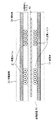
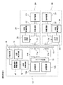
図1は実施形態1に係る無線電力伝送システムの構成を示すブロック図である。また、図2は図1の送電コイル11と受電コイル21の配置を示す縦断面図である。すなわち、図2は、送電装置10と受電装置20および、それらの送電コイル11及び受電コイル21の位置関係を示す。本実施形態に係る無線電力伝送システムは、送電装置10及び受電装置20を備え、送電装置10から受電装置20へ非接触で交流電力を送る。図1に示すように、送電装置10は、送電コイル11と、送電回路12と、位置検出回路13と、送電制御回路14と、位置検出コイル15と、受信回路16とを備えて構成される。また、受電装置20は、受電コイル21と、受電回路22と、負荷装置23と、受電制御回路24と、送信回路25とを備えて構成される。
FIG. 1 is a block diagram illustrating a configuration of a wireless power transmission system according to the first embodiment. 2 is a longitudinal sectional view showing the arrangement of the
図1において、送電回路12は、電源装置(図示せず)から直流又は交流の電力供給を受けて、送電コイル11に交流電力を供給する。ここで、送電回路12は、送電コイル11及び受電コイル21の間で通過可能な周波数(伝送周波数)を有する交流電力を発生する。通常、送電コイル11は、交流電力を通過させるために、交流電力の周波数に等しい共振周波数を有する。ただし、交流電力が通過するのであれば、交流電力の周波数と送電コイル11の共振周波数とは不一致であってもよい。同様に、受電コイル21は、交流電力を通過させるために、交流電力の周波数に等しい共振周波数を有する。ただし、交流電力が通過するのであれば、交流電力の周波数と受電コイル21の共振周波数とは不一致であってもよい。
In FIG. 1, a
図2に示すように、受電コイル21は、受電装置20が送電装置10に対向して配置されたときに送電コイル11と電磁的に結合可能であり、無接点で電力を伝送可能になる。しかしながら、受電コイル21が送電コイル11と対向していなく互いの位置がずれている場合には、結合が低下するために電力を効率よく伝送できなくなる。このため、受電コイル21と送電コイル11の間に位置検出コイル15を備え、受電コイル21と送電コイル11の位置を一致させるようにしている(例えば特許文献2参照)。このとき、位置検出回路13は検出パルスを位置検出コイル15に供給し、受電装置20の受電コイル21から反射して戻ってくる電圧もしくは電流を検出することにより、受電コイル21を検出する。さらに、図2に示すように、位置検出コイル15は、受電コイル21の位置の検出をより正確に行えるように、送電装置10が受電装置20に対向する面に沿った領域であって、送電コイル11よりも受電装置20に近い領域又は位置に備えられている。
As shown in FIG. 2, the
なお、図2に示すように、送電コイル11と受電コイル21は、それぞれ磁性体17と磁性体26をそれぞれ備え、送電時にコイル間に生じる磁界を閉じ込めることで周囲からの影響を低減することで、周囲環境に左右されずに効率よく電力を伝送できる構造を実現している。
In addition, as shown in FIG. 2, the
図3は図1の送電コイル11と受電コイル21と位置検出コイル15の構成例を示す斜視図である。図3は、一例として、位置検出コイル15が、Y方向に平行な長手方向を有する1回巻きのコイル素子であってかつX方向に対して互いに平行となるように4つの位置検出コイル素子15a〜15dを等間隔に配置した例であり、本例をもとに動作の説明を行う。
3 is a perspective view showing a configuration example of the
まず、位置検出コイル素子15aに、位置検出回路13から検出パルス(信号)が送られ受電コイル21から反射して戻ってくる信号の電圧もしくは電流を検出し強度を位置検出回路13のメモリに記憶する。ここで、検出パルスのことを単に信号と以後呼ぶことにする。次に、位置検出回路13から位置検出コイル素子15bに信号を送り、同様に反射して戻ってくる信号の電圧もしくは電流を検出してその強度(以下、「反射強度」という。)を位置検出回路13のメモリに記憶する。以下同様に、位置検出コイル素子15c、15dと行い、位置検出回路13のメモリに記憶された各位置検出コイル素子15a〜15dからの反射強度を比較して、例えば、受電コイルとの電磁結合により、受電コイルおよび受電回路でエネルギーが消費される場合には、最も反射波の強度が小さい位置検出コイル素子の近くに受電コイル21があると位置検出回路13により判定(判断とも言う)する。
First, the detection pulse (signal) is sent from the
また、上記方法と別の方法として、例えば、反射して戻ってきて検出された信号の電圧もしくは電流の変化量(位置検出コイル素子から十分離れた位置にある受電コイルを基準値とした時、上記基準値と反射し戻ってきた信号の電圧値もしくは電流値との差)が所定の閾値を超えたとき、位置検出コイル素子の近くに受電コイル21があると位置検出回路13により判断する方法もある。
In addition, as a method different from the above method, for example, the amount of change in the voltage or current of the signal detected after being reflected back (when the power receiving coil at a position sufficiently away from the position detection coil element is used as a reference value, A method for determining by the
そして、送電制御回路14は、受信した信号の各々の強さに基づいて、送電装置の設置面に設置された受電装置の位置を判断する。
And the power
なお、判定の精度を向上させるために、強度が最大の位置検出コイル素子だけでなく、選択された位置検出コイル素子近傍の複数の位置検出コイル素子の反射強度の値を用いて、受電コイル21から最も近傍に位置する、適切な位置検出コイル素子を推定する手法もあるがここでは詳細は記述しない。ここで、図3の場合には、例えば位置検出コイル素子15aが受電コイル21に最も近く、反射強度が最も強くなり、受電コイル21が、X方向に対して、位置検出コイル素子15aの位置にあると位置検出回路13にて判定される。
In order to improve the accuracy of the determination, not only the position detection coil element having the maximum strength but also the value of the reflection intensity of a plurality of position detection coil elements in the vicinity of the selected position detection coil element is used. There is also a method for estimating an appropriate position detection coil element located closest to the position, but details are not described here. Here, in the case of FIG. 3, for example, the position
なお、図3では、説明のため、Y方向に平行な長手方向を有する位置検出コイル素子をX方向に複数並べて、X方向の位置を検出する方法について例を挙げて説明したが、本開示はこれに限られず、図4の方法を用いてもよい。 In FIG. 3, for the sake of explanation, the method for detecting the position in the X direction by arranging a plurality of position detection coil elements having a longitudinal direction parallel to the Y direction in the X direction has been described. The method of FIG. 4 may be used without being limited to this.
図4は図3の変形例であって、受電コイル21と位置検出コイル15の構成例を示す斜視図である。図4に示すように、さらに、X方向に平行な長手方向を有する複数の位置検出コイル素子15e〜15iをY方向に並置し、Y方向の位置を検出する構成にすることで、XY面の2次元において受電コイル21の位置を検出することが可能になる。なお、図4では、送電コイル11は、説明で不要のため図示していない。図4の場合、例えば、X方向で並置された位置検出コイル素子15a〜15dまでの反射強度を調べた後に、Y方向で並置された位置検出コイル素子15e〜15iまでの反射強度を調べることで2次元的な位置検出が可能になる。
FIG. 4 is a perspective view showing a configuration example of the
なお、ここでは、X方向に4個の位置検出コイル素子15a〜15dを並置し、Y方向に5個の位置検出コイル素子15e〜15iを並置した例を挙げて説明したが、本開示はこれに限らず、受電コイルを検出する範囲によってその他の個数の組み合わせも可能である。また、図3と図4では、位置検出コイル素子を1回巻きのコイルで構成されている場合を例に挙げて説明を行ったが、これに限られるものではなく、2回巻き以上のコイルの構成も可能である。巻き数を増やすことで、受電コイル21との結合を強くすることが可能になり、さらに反射強度を強める効果がある。また、図3及び図4においては、位置検出コイル素子15a〜15iを矩形コイルで構成されている場合を例に挙げて説明を行ったが、これに限られるものではなく、正方形、円形、長円、楕円、その他のコイル形状でも可能である。
Here, an example in which four position
図5は図1の位置検出コイル15の回路例の構成を示すブロック図である。図5において、位置検出コイル15と、位置検出回路13及び受信回路16との接続を示す。図5において、位置検出コイル15の回路は、スイッチ回路15kと、スイッチ回路15jと、位置検出コイル素子15a〜15i(位置検出コイル素子15a〜15iを単に位置検出コイルと呼んでもよい)とを備えて構成される。スイッチ回路15kは位置検出回路13と受信回路16とのうちの1つを選択してスイッチ回路15jに接続する一方、スイッチ回路15jは位置検出コイル素子15a〜15iのうちの1つを選択してスイッチ回路15kに接続する。ここで、スイッチ回路15j,15kの切り替えは送電制御回路14で制御する。送電制御回路14によりスイッチ回路15jと15kを直接制御信号により制御することも可能である。このように構成することにより最も簡単な構成で制御ができるという利点があるが、これに限られるものではない。例えば、送電制御回路14は、位置検出回路13と受信回路16を制御し、位置検出回路13と受信回路16からの制御信号によりスイッチ回路15j,15kを制御することも可能である。これにより、位置検出回路13もしくは受信回路16とスイッチ回路15j,15kとの同期をとる必要が無くなり、高精度な制御を行わなくてすむという利点がある。
FIG. 5 is a block diagram showing a configuration of a circuit example of the
本実施形態では、スイッチ回路15jは位置検出コイル素子15a〜15iのうちで、反射強度が最も弱くなる位置検出コイル素子選択している。ある例においては、反射強度が最も強くなる場合もある。
In the present embodiment, the
しかし、図19Aに示すように、位置検出コイル素子を選択せず、位置検出コイル素子15a〜15iの全てをスイッチ回路15qと接続させてもよい。上記位置検出コイル素子のいずれかのコイル素子を介して、受電装置20からの無線信号を取得してもよい。この場合、位置検出コイルを介して送電装置の設置面に受電装置が設置されかどうかを、受電装置からの信号を検出して判断する。具体的には、位置検出回路から入力された上記信号の強度が所定時間一定範囲内の場合(基準値を所定時間超えなかったと判断した場合)、送電制御回路は、送電装置の設置面に受電装置が設置されたと判断する。送電装置の設置面に受電装置が設置されたと判断したとき、送電制御回路は、スイッチ回路15qを用いて、位置検出コイル素子15a〜15iの全ての電気的接続先を位置検出回路13から受信回路16に切り替える。そして、位置検出コイルを介して上記受信回路に無線信号を入力させる。
However, as shown in FIG. 19A, the position detection coil elements may not be selected, and all the position
また、本実施形態では、複数の位置検出コイル素子15a〜15iを用いたが、図19Bに示すように、1つの位置検出コイル15pでもよい。この場合、図19Bに示すように、1つの位置検出コイル15pを介して上記送電装置の設置面に受電装置が設置されかどうかを、受電装置からの信号を検出して判断する。具体的には、位置検出回路から入力された上記信号の強度が所定時間一定範囲内の場合(基準値を所定時間超えなかったと判断した場合)、送電制御回路は、位置検出コイルと上記位置検出回路の電気的接続から位置検出コイルと受信回路の電気的接続に切り替え、位置検出コイルを介して上記受信回路に無線信号を入力させる。
In the present embodiment, a plurality of position
図1において、送電制御回路14は、位置検出回路13により受電コイル21を検出したとき、送電回路12から送電コイル11への交流電力の供給を制御する。受電装置20の受電回路22は、受電コイル21を介して送電装置10から受けた交流電力を整流及び平滑して負荷装置23に供給する。負荷装置23は、充電対象のバッテリ又は電力を消費する他の回路を含む。受電回路22及び負荷装置23の間にDC/DCコンバータを挿入してもよい(図示せず)。これにより、送電コイル11及び受電コイル21の結合係数あるいは負荷装置23のインピーダンスによらず、定電圧の電力を負荷装置23に供給することができる。
In FIG. 1, the power
図6は図1の送電コイル11の構成例を示す上面図である。また、図7は図1の送電コイル11の回路例を示すブロック図である。
FIG. 6 is a top view showing a configuration example of the
図6において、複数の送電コイル素子11a〜11iを、送電コイル素子が実質的に全範囲をカバーするように2次元に配置することで送電可能な範囲を広げている。図7において、送電コイル11の回路は、スイッチ回路11sと、送電コイル素子11a〜11iとを備えて構成される。スイッチ回路11sは送電コイル素子11a〜11iのうちの1つを選択して送電回路12に接続する。この場合、位置検出回路13により検出された受電コイル21の位置に最も近い送電コイル素子をスイッチ回路11sを介して送電回路12に接続することで、常に伝送効率の高い無接点電力伝送が可能になるという利点がある。図6では、送電コイル素子を円形コイルで構成されている場合を例に挙げて説明を行ったが、これに限られるものではなく、正方形、矩形、円形、長円、楕円、その他の形状のコイルでも可能である。特に、正方形、矩形のコイル形状では、隙間を小さく配置することが可能になり、受電コイルとの結合の弱い範囲を少なくできるという利点がある。
In FIG. 6, a plurality of power
図8は図1の送電コイル11の別の構成例を示す上面図である。図8においては、送電コイル11は、送電コイル素子11tと、矢印11maで示すX方向に送電コイル素子11tを移動させるためのレール11k及びモーター11mと、矢印11paで示すY方向に送電コイル素子11tを移動させるためのレール11n及びモーター11pを備えて構成される。これにより、検出された受電コイル21の位置に送電コイル素子11tをより正確に位置合わせすることが可能になり、伝送効率の高い無接点電力伝送が可能になるという利点がある。
FIG. 8 is a top view showing another configuration example of the
図1において、受電装置20は、さらに、受電制御回路24と送信回路25を備えたことを特徴としている。受電制御回路24は、受電装置20における所望な電圧及び電流(設定してほしい電圧及び電流)並びに充電容量、受電装置20で検出された電圧、電流及び充電量、温度センサで検出された温度情報等の装置情報(以下、装置情報という。)を、無線信号での送信に必要なデータ信号に変換した後、送信回路25に出力する。送信回路25は、入力されたデータ信号に従って、無線搬送波を所定のデジタル変調方式で変調することで変調された無線信号を発生し、受電コイル21から送電装置10に送信する。
In FIG. 1, the
送電装置10においては、位置検出コイル15において無線信号を受信して受信回路16に出力する。受信回路16は無線信号をデータ信号に復調し、復調したデータ信号を送電制御回路14に送り、送電回路12の送電電力、周波数、位相等の送電パラメータを制御する。これにより、例えば、受電装置20の負荷装置23がバッテリの場合には、上記装置情報を受電装置20から送電装置10にフィードバックすることが可能になり、これに基づいて送電制御することで最適な送電を実現することができる。具体的には、例えば、以下の通りである。
(1)検出された電圧及び電流がそれぞれ、所望な電圧及び電流となるように送電パラメータを制御する。
(2)検出された温度情報が所定のしきい値以上となれば、送電を中止する。
(3)検出された充電量が所定のしきい値以上となれば、送電を中止する。
In the
(1) The power transmission parameters are controlled so that the detected voltage and current are the desired voltage and current, respectively.
(2) If the detected temperature information is equal to or greater than a predetermined threshold, power transmission is stopped.
(3) If the detected charge amount is equal to or greater than a predetermined threshold value, power transmission is stopped.
ここで、送電装置10における装置情報の受信について、図3を用いて説明する。無線通信の受信は位置検出コイル15を用いて実施される。図3の場合、受電コイル21に最も近いと判定された位置検出コイル素子15aを用いて無線信号を受信することにより、最も強い受信信号電力が得られることになる。この場合、最も望ましい形態として、位置検出のステップで検出された位置検出コイル素子を、あらかじめ受信コイルとしてスイッチ回路15j,15k(図5)で選択してから受電コイル21から信号を送信することで、最も強い受信信号電力が得られるという利点がある(図5参照)。
Here, reception of device information in the
さらに、受電装置20からの装置情報の受信のための受信コイルに位置検出コイル15を用いることで、送信コイルである受電コイル21との距離(図2の上下間の距離)が最も近く、送信コイルと受信コイル間に金属等の部材が入らない構成にすることで最もコイル間の結合を強めることが可能になり、より受信信号電力を高める効果がある。
Furthermore, by using the
例えば特許文献1では、送電コイルと受電コイルの位置合わせについて記載されていないが、例えば特許文献2の位置合わせ構成を採用することによって高効率な送電を行う場合には、送信コイル(受電装置20の受電コイル21)と受信コイル(送電装置10の送電コイル11)との間に金属製の位置検出コイル15が入ることにより、金属物による電磁界の変化による受信信号電力の低下、さらには、受信コイルと送信コイル間の距離が離れることによる受信信号電力の低下が生じるため情報伝達ができない範囲が生じる可能性があるが、本実施形態の構成ではこれらの課題を解決することができる優れた構成である。
For example,
さらに、電力を伝送する送電周波数と、情報を伝送するための無線通信の周波数を異なる周波数で行うことも可能である。無線通信の信号の周波数が、送電の信号の周波数と同じ場合には、受信コイルで無線通信の信号と送電の信号の両方を受信してしまうために、送電の信号が電磁ノイズとして働き受信回路16での相対的な受信信号電力が低下するために復調できないという課題があった。そこで、無線通信の周波数と送電周波数とを異なる周波数にすることで、受信コイルで送電の信号を受信することが無いために相対的な受信信号電力の低下が起こらず復調可能であり、電力の無線伝送と無線通信を同時に行うことができるために、時間平均的な電力伝送の伝送効率の低下を避けるという効果がある。 Furthermore, the power transmission frequency for transmitting power and the frequency of wireless communication for transmitting information can be performed at different frequencies. When the frequency of the wireless communication signal is the same as the frequency of the power transmission signal, both the wireless communication signal and the power transmission signal are received by the receiving coil. There was a problem that demodulation was not possible because the relative received signal power at 16 decreased. Therefore, by setting the radio communication frequency and the power transmission frequency to different frequencies, the reception coil does not receive a power transmission signal, so that the received signal power does not decrease and can be demodulated. Since wireless transmission and wireless communication can be performed simultaneously, there is an effect of avoiding a decrease in transmission efficiency of time-average power transmission.
例えば特許文献3には、通信装置を備えるとともに、送電周波数の整数倍で無い異なる周波数を用いることで情報通信の確実性を向上させていることが開示されているが、通信装置を備えることは、新たな部材の増加につながり、装置の大型化やコストの増加に繋がるとともに、受電コイルと送電コイルの位置合わせ機能が無いために、さらに、例えば特許文献2記載の位置検出コイルを用いる場合には更なるコストの増加の懸念があった。
For example,
一方、本実施形態では、送信コイルは、受電コイル21を使用し、受信コイルは位置検出コイル15を用いることで、電力伝送の高効率化と無線通信を両立し、かつ装置の大型化やコストの増加に繋がらない優れた無線伝送装置を提供することが可能である。なお、本実施形態においても、無線通信の周波数を送電周波数の整数倍でない周波数を使うことで、送電周波数の高調波成分を受信コイルで受信しないことで相対的な受信信号電力の低下を避けることは言うまではない。例えば、送電周波数を130kHz、送信周波数を1000kHzとする。
On the other hand, in the present embodiment, the transmission coil uses the
さらに、受電装置20から送電装置10の無線通信だけでなく、送電装置10から受電装置20への無線通信を行うことも可能である。これにより、双方向の情報の伝達が可能になり、より細かな制御が可能になるという効果がある。その変形例を図9に示す。
Furthermore, not only wireless communication from the
図9は実施形態1の第1の変形例に係る無線電力伝送システムの構成を示すブロック図である。図9において、実施形態1の第1の変形例に係る無線電力伝送システムは、図1の実施形態1に係る無線電力伝送システムに比較して以下の点が異なる。
(1)送電装置10はさらに、位置検出コイル15と送電制御回路14との間に、送信回路18を備えた。
(2)受電装置20はさらに、受電コイル21と受電制御回路24との間に、受信回路27を備えた。
FIG. 9 is a block diagram illustrating a configuration of a wireless power transmission system according to a first modification of the first embodiment. In FIG. 9, the wireless power transmission system according to the first modification of the first embodiment is different from the wireless power transmission system according to the first embodiment of FIG. 1 in the following points.
(1) The
(2) The
図9において、送電制御回路14は、装置指示信号(例えば、装置情報を含むデータ信号の無線信号を送信するように指示信号、当該無線信号を受信したことを確認するための受信確認信号など)のデータ信号を発生して送信回路18に出力する。送信回路18は入力されるデータ信号を従って、無線搬送波信号を変調して無線信号を発生した後、位置検出コイル15及び受電コイル21を介して受電装置20の受信回路27に送信する。受信回路27は受信した無線信号をデータ信号に復調して、当該データ信号内の装置指示信号を受電制御回路24に出力する。
In FIG. 9, the power
従って、送電装置10から受電装置20への無線通信は、送信コイルとして位置検出コイル15を用いることが可能である。これにより、追加部材無しに送電装置10からの送信が可能になるとともに、受電装置20に最も近いことでより、受電装置20の受信回路に最も強い受信信号電力が得られるという効果がある。この場合も、例えば、送電周波数(例えば130kHz)と異なる無線周波数を選定し、かつ、無線通信の送受信は送信周波数を同じ周波数(例えば1000kHz)とし、送電装置10からの送信と受電装置20からの送信を時分割で交互に行うことで、送電から影響を受けない双方向の無線通信を実現する無線電力伝送システムを提供することができる。また、例えば、送電周波数(例えば130kHz)と異なる無線周波数を選定し、かつ、無線通信の送受信においても送信周波数が異なる周波数(例えば1000kHzと1500kHz)とすることで、送電装置10からの送信と受電装置20からの送信を同時に行うことができる無線電力伝送システムを提供することができる。
Therefore, the wireless communication from the
図10は実施形態1の第2の変形例に係る無線電力伝送システムの構成を示すブロック図である。図10において、実施形態1の第2の変形例に係る無線電力伝送システムは、図9の実施形態1の第1の変形例に係る無線電力伝送システムに比較して以下の点が異なる。
(1)送電装置10において、送電コイル11と送電制御回路14との間に、送信回路18を備えた。
FIG. 10 is a block diagram illustrating a configuration of a wireless power transmission system according to the second modification of the first embodiment. 10, the wireless power transmission system according to the second modification of the first embodiment is different from the wireless power transmission system according to the first modification of the first embodiment of FIG. 9 in the following points.
(1) In the
従って、図10に示すように、送電装置10から受電装置20への無線通信は、送信コイルとして送電コイル11を用いる。これにより、追加部材無しに配線の設計変更のみで送電装置10からの送信が可能になるという効果がある。
Therefore, as shown in FIG. 10, the wireless communication from the
以上のように、本実施形態によれば、受電装置20の負荷装置23に応じた最適な送電を実現する送電装置10を提供することができる。さらに、位置検出コイル15により、受電コイル21の位置を検出することで送電コイル11との位置を一致させることが可能になり、最も伝送効率の高い無接点電力伝送が可能になる。また、本構成により、受電コイル21を、受電装置20の送信コイルに使用することにより、部品点数の削減の効果がある。また、受電装置20の薄型化および小型化の効果がある。さらに、送電装置10の受信コイルに位置検出コイル15を用いることにより、部品点数の削減、送電装置の薄型化および小型化の効果に加えて、位置検出コイル15が受電装置20に最も近い位置にあることで受信信号の強度が最も強く、より正確な復調が可能になるという効果がある。また、さらに、位置検出のステップで最も反射強度が強い位置検出コイル素子を、受信コイルに選択することにより、確実に受信電力を最大化することが可能になるという効果がある。これらにより、受電装置20において送信信号の電力がより小さな電力で送信することが可能になり、受電装置20の消費電力が低減できる優れた送電装置及び無線電力伝送システムを提供することが可能になる。
As described above, according to the present embodiment, it is possible to provide the
実施形態2.
以下、本開示の実施形態2に係る無線電力伝送システムについて、図面を参照しながら説明する。
Embodiment 2. FIG.
Hereinafter, the wireless power transmission system according to the second embodiment of the present disclosure will be described with reference to the drawings.
図11は実施形態2に係る無線電力伝送システムの構成を示すブロック図である。また、図12は図11の受電コイル21,31と位置検出コイル15の構成例を示す斜視図である。図11において、実施形態2に係る無線電力伝送システムは、図1の実施形態1に係る無線電力伝送システムに比較して以下の点が異なる。
(1)受電装置20に加えて、受電装置30をさらに備えた。
(2)送電装置10はさらに、複数の受電装置20,30に関する制御を行う複数端末制御回路41をさらに備えた。
FIG. 11 is a block diagram illustrating a configuration of a wireless power transmission system according to the second embodiment. 12 is a perspective view showing a configuration example of the power receiving coils 21 and 31 and the
(1) In addition to the
(2) The
ここで、受電装置30は、受電装置20と同様に、受電コイル31と、受電回路32と、負荷装置33と、受電制御回路34と、送信回路35とを備えて構成され、同様に動作する。なお、送電装置10では、1つの送電回路12と1つの送電コイル11により2個の受電装置20,30に送電する。
Here, similarly to the
図12において、一例として、送電コイル11として、図6に図示した複数の送電コイル素子11a〜11iを備えた場合を例に説明を行う。複数端末制御回路41は、位置検出回路13からの受電装置20,30の個数と位置情報(以下、個数及び位置情報という。)に基づいて、複数の送電コイル素子11a〜11iのうちのいずれを選択するかを決定してスイッチ回路11sを切り替えるとともに、受信回路16からの受電装置20,30からの負荷装置23,33の上記装置情報及び上記個数及び位置情報に基づいて、負荷装置23,33に対する各送電電力の電力量を決定して、その情報を送電制御回路14に出力し、これに基づいて送電制御回路14は受電装置20,30に対応する各送電電力の電力量を制御する。
In FIG. 12, as an example, the case where the
また、2個の受電装置20と30を同時に充電もしくは給電する場合には、複数端末制御回路41は、図7に図示した送電コイル11のスイッチ回路11sにより2個の送電コイル素子を送電回路12に接続するように制御する。この場合の送電コイル素子の選定には、位置検出回路13と位置検出コイル15により、2個の受電コイル21と31の位置を検出し、複数端末制御回路41からの制御により、それぞれの受電コイルに最も近い送電コイル素子を選択し送電回路12に接続する。また、1つの受電装置(例えば受電装置20)を充電あるいは給電した後に、残りの受電装置(例えば受電装置30)を充電あるいは給電する場合には、複数端末制御回路41からの制御により、図7に図示した送電コイル11のスイッチ回路11sを制御し、それぞれの受電コイル21,31に対応した1つの送電コイル素子(位置検出により選択された送電コイル素子)を、それぞれの送電期間において送電回路12に接続する。なお、位置検出のステップを実施形態1と同様に実行するが、受電コイル21の位置の情報と受電コイル31の位置の情報を位置検出回路13のメモリに格納することで、最も近い送電コイル素子を選定することが可能になる。
When simultaneously charging or feeding the two
複数の受電装置20,30がある場合には、受電装置20,30側からの無線通信の送信が混信する恐れがある。従って、例えば、受電装置20のからの送信周波数と受電装置30からの送信周波数を異なる周波数で行うことで、無線通信の混信を避けることがきる。例えば、受電装置20からの送信周波数を1000kHzとし、受電装置30からの送信周波数を1500kHzとする。また、例えば、受電装置20からの送信周波数を1000kHzとし、受電装置30からの送信周波数を送電周波数の130kHzとすることも可能である。これにより、新たな周波数を使用することなく、2個の無線通信の混信を回避することができる優れた無線電力伝送システムを提供することが可能になる。さらに例えば、受電装置20のからの送信周波数と受電装置30のからの送信周波数を同じ周波数(例えば1000kHz)とし、受電装置20のからの送信時間と受電装置30からの送信時間を異なる時間(タイムスロット)で行うことで、無線通信の混信を避けることがきる。これにより、新たな周波数を使用することなく、2個の無線通信の混信を回避することができる優れた無線電力伝送システムを提供することが可能になる。
When there are a plurality of
さらに、受電装置20,30から送電装置10の無線通信だけでなく、送電装置10から受電装置20,30への無線通信を行うことも可能である。これにより、双方向の情報の伝達が可能になり、より細かな制御が可能になるという効果がある。当該変形例を図13に示す。
Furthermore, not only wireless communication from the
図13は実施形態2の第1の変形例に係る無線電力伝送システムの構成を示すブロック図である。実施形態2の第1の変形例に係る無線電力伝送システムは、図11の実施形態2に係る無線電力伝送システムに比較して以下の点が異なる。
(1)送電装置10はさらに、位置検出コイル15と複数端末制御回路41との間に、送信回路18を備えた。
(2)受電装置20はさらに、受電コイル21と受電制御回路24との間に、受信回路27を備えた。また、受電装置30はさらに、受電コイル31と受電制御回路34との間に、受信回路37を備えた。
FIG. 13 is a block diagram illustrating a configuration of a wireless power transmission system according to a first modification of the second embodiment. The wireless power transmission system according to the first modification of the second embodiment is different from the wireless power transmission system according to the second embodiment of FIG. 11 in the following points.
(1) The
(2) The
図13において、送電装置10から受電装置20,30への無線通信は、送信コイルとして位置検出コイル15を用いることが可能である。これにより、追加部材無しに送電装置10からの送信が可能になるとともに、受電装置20,30に最も近い距離により、受電装置20,30の受信回路に最も強い受信信号電力が得られるという効果がある。この場合も、例えば、送電周波数(例えば130kHz)と異なる無線周波数を選定し、かつ、無線通信の送受信は送信周波数を同じ周波数(例えば1000kHz)とし、送電装置10からの送信と受電装置20,30からの送信を時分割で交互に行うことで、送電から影響を受けない双方向の無線通信を実現する無線電力伝送システムを提供することができる。また、例えば、送電周波数(例えば130kHz)と異なる無線周波数を選定し、かつ、受電装置20における無線通信の送受信においても送信周波数が異なる周波数(例えば1000kHzと1500kHz)とし、受電装置30における無線通信の送受信においても送信周波数が異なる周波数(例えば1100kHzと1600kHz)とすることで、送電装置10からの送信と受電装置20,30からの送信を同時に行うことができる無線電力伝送システムを提供することができる。さらに例えば、送電周波数(例えば130kHz)と異なる無線周波数を選定し、かつ、受電装置20のからの送信周波数と受電装置30のからの送信周波数を同じ周波数(例えば1000kHz)とし、受電装置20のからの送信時間と受電装置30からの送信時間を異なる時間(タイムスロット)で行い、かつ、送電装置10のから受電装置20への送信周波数と受電装置30への送信周波数を同じ周波数(例えば15000kHz)とし、送電装置10のから受電装置20への送信時間と受電装置30への送信時間を異なる時間(タイムスロット)で行うことで、無線通信の混信を避けることがきる。これにより、送電装置10からの送信と受電装置20,30からの送信を同時に行うことができる無線電力伝送システムを提供することができる。
In FIG. 13, the
図14は実施形態2の第2の変形例に係る無線電力伝送システムの構成を示すブロック図である。図14において、実施形態2の第2の変形例に係る無線電力伝送システムは、図13の実施形態2の第1の変形例に係る無線電力伝送システムに比較して以下の点が異なる。
(1)送電装置10において、送電コイル11と複数端末制御回路41との間に、送信回路18を備えた。
FIG. 14 is a block diagram illustrating a configuration of a wireless power transmission system according to a second modification of the second embodiment. 14, the wireless power transmission system according to the second modification example of the second embodiment is different from the wireless power transmission system according to the first modification example of the second embodiment in FIG. 13 in the following points.
(1) In the
従って、図14に示すように、送電装置10から受電装置20,30への無線通信は、送信コイルとして送電コイル11を用いることも可能である。これにより、追加部材無しに送電装置10からの送信が可能になる優れた送電装置及び無線電力伝送システムを提供することが可能になる。
Therefore, as shown in FIG. 14, in the wireless communication from the
本実施形態では、2個の受電装置20,30を充電あるいは給電する場合を用いて説明したが、これに限られるものではない。3つ以上の受電装置20,30等を充電あるいは給電する場合においても2個の受電装置20,30のときと同様に、複数端末制御回路41を備える。複数端末制御回路41は、位置検出回路13からの受電装置20,30等の個数と位置情報、並びに受信回路16からの受電装置20,30等からの負荷装置23,33等の上記装置情報に基づいて、負荷装置23,33等に対する送電電力の電力量を決定して、その情報を送電制御回路14に伝送し、受電装置20,30等に状態に対応して送電の電力量を制御する。
In the present embodiment, the case where the two
また、位置検出回路13は全ての受電装置20,30等の受電コイルの位置を検出し、複数端末制御回路41からの制御により、各受電コイル21,31等に最も近い送電コイル素子11a〜11iのうちの1つを選択し、送電回路12に接続し、同時に充電あるいは給電を可能にする。また、1つの受電装置20,30等を順々に充電あるいは給電する場合には、複数端末制御回路41からの制御により、図7に図示した送電コイル11のスイッチ回路11sにより、それぞれの受電コイル21,31等に対応した1つの送電コイル素子(位置検出により選択された送電コイル素子)を、それぞれの送電期間において送電回路12に接続する。なお、位置検出のステップを実施形態1と同様に実行し、受電コイル21の位置の情報と受電コイル31の位置の情報等を位置検出回路13に格納することで、最も近い送電コイル素子を選定することが可能になる。
Further, the
さらに、本実施形態では、図6に示すような、複数の送電コイル素子11a〜11iにより構成された送電コイル11を例に挙げて説明したが、これに限られるものでなく、例えば、図8に図示したようなモーター11m,11pによる送電コイル素子11tを移動させ、受電コイルとの位置を合わせる構成も可能である。この場合には、モーター11m,11pで位置を移動する送電コイル素子11tは、同時に送電する受電装置20,30の数と同じ数が必要になるが、各々の受電装置20,30の受電コイル21,31に正確に位置をあわすことが可能になり、電力の伝送効率がより高い無線電力伝送システムを提供することができるという利点がある。
Furthermore, in this embodiment, although demonstrated taking the case of the
以上説明したように、本実施形態によれば、複数の受電装置20,30がある場合に、各々の負荷装置23,33に応じた最適な送電を実現する送電装置10を提供することができる。さらに、位置検出コイル15により、各受電コイル21,31の位置を検出することで送電コイル11との位置を一致させることが可能になり、最も伝送効率の高い無接点電力伝送が可能になる。また、本構成により、各受電コイル21,31を、各受電装置20,30の送信コイルに使用することにより、部品点数の削減の効果がある。また、各受電装置20,30の薄型化および小型化の効果がある。さらに、送電装置10の受信コイルに位置検出コイル15を用いることにより、部品点数の削減、送電装置の薄型化および小型化の効果に加えて、位置検出コイル15が各受電装置に最も近い位置にあることで受信信号の強度が最も強く、より正確な復調が可能になるという効果がある。また、さらに、位置検出のステップで最も反射強度が強い位置検出コイル素子を、受信コイルに選択することにより、確実に受信電力を最大化することが可能になるという効果がある。これらにより、各受電装置において送信信号の電力がより小さな電力で送信することが可能になり、各受電装置20,30の消費電力が低減できるという優れた効果がある。
As described above, according to the present embodiment, when there are a plurality of
実施形態3.
以下、本開示の第3の実施形態に係る無線電力伝送システムについて、図面を参照しながら説明する。
Hereinafter, a wireless power transmission system according to the third embodiment of the present disclosure will be described with reference to the drawings.
図15は実施形態3に係る無線電力伝送システムの構成を示すブロック図である。また、図16は図15の送電コイル回路11Aの回路例の構成を示すブロック図である。図15及び図16において、実施形態3に係る無線電力伝送システムは、図11の実施形態2に係る無線電力伝送システムに比較して以下の点が異なる。
(1)送電コイル11に代えて、図6の構成を有する図16の送電コイル素子11a〜11i(図15においては、選択された2個の送電コイル素子11q,11rを図示する)及びそれを選択して送電回路12a,12bに接続するスイッチ回路19を含む送電コイル回路11Aを備えた。
(2)送電回路12に代えて、2個の送電回路12a,12bを備えた。
FIG. 15 is a block diagram illustrating a configuration of a wireless power transmission system according to the third embodiment. FIG. 16 is a block diagram showing a configuration of a circuit example of the power
(1) Instead of the
(2) Instead of the
本実施形態では、2個の受電装置20と30を備え、各受電装置20,30に対してそれぞれ送電装置10の2個の送電回路12a,12bにより送電することを特徴としている。本実施形態では、第2の実施形態と同様に、複数端末制御回路41は、位置検出回路13からの受電装置20,30の個数及び位置情報に基づいて、複数の送電コイル素子11a〜11i(図6及び図16)のうちのいずれの少なくとも1つで最大2個を選択するか、並びに、選択された1個又は2個の送電コイル素子をどの送電回路12a,12bに接続するかを決定してスイッチ回路19を切り替えるとともに、受信回路16からの受電装置20,30からの負荷装置23,33の上記装置情報及び上記個数及び位置情報に基づいて、負荷装置23,33に対する各送電電力の電力量を決定して、その情報を送電制御回路14に出力し、これに基づいて送電制御回路14は受電装置20,30に対応する送電回路12a,12bからの各送電電力の電力量を制御する。なお、位置検出回路13と位置検出コイル15により、2個の受電コイル21と31の位置を検出する。
In the present embodiment, two
すなわち、図16に図示したように、複数端末制御回路41からの制御により、送電コイル素子11a〜11iの中で、それぞれの受電コイル21,31に最も近い送電コイル素子11q,11rを選択し、スイッチ回路19により2個の送電コイル素子11q,11rをそれぞれ送電回路12a,12bに接続する。この中で、受電コイル21に送電するように選択された送電コイル素子が図15の送電コイル素子11qにあたり、受電コイル31に送電するように選択された送電コイル素子が図15の送電コイル素子11rに対応する。これにより、2個の受電装置20と30を同時に充電もしくは給電することが可能になる。また、本構成によれば、受電装置20,30に対して個別の送電回路12a,12bを備えているため、複数端末制御回路41からの制御により、それぞれの負荷装置23,33に最適な送電が可能になる。なお、位置検出のステップを実施形態1と同様に実行し、受電コイル21の位置の情報と受電コイル31の位置の情報を位置検出回路13に格納することで、最も近い送電コイル素子を選定することが可能になる。
That is, as illustrated in FIG. 16, the power
本実施形態においても受電装置20,30が複数ある場合には、受電装置20,30側からの無線通信の送信が混信する恐れがある。従って、例えば、受電装置20からの送信周波数と受電装置30からの送信周波数を異なる周波数で行うことで、無線通信の混信を避けることがきる。例えば、受電装置20からの送信周波数を1000kHzとし、受電装置30からの送信周波数を1500kHzとする。また、例えば、受電装置20からの送信周波数を1000kHzとし、受電装置30からの送信周波数を送電周波数の130kHzとすることも可能である。これにより、新たな周波数を使用することなく、2個の無線通信の混信を回避することができる優れた無線電力伝送システムを提供することが可能になる。さらに例えば、受電装置20のからの送信周波数と受電装置30のからの送信周波数を同じ周波数(例えば1000kHz)とし、受電装置20のからの送信時間と受電装置30からの送信時間を異なる時間(タイムスロット)で行うことで、無線通信の混信を避けることがきる。これにより、新たな周波数を使用することなく、2個の無線通信の混信を回避することができる優れた無線電力伝送システムを提供することが可能になる。
Also in the present embodiment, when there are a plurality of
さらに、受電装置20,30から送電装置10の無線通信だけでなく、送電装置10から受電装置20,30への無線通信を行うことも可能である。これにより、双方向の情報の伝達が可能になり、より細かな制御が可能になるという効果がある。
Furthermore, not only wireless communication from the
図17は実施形態3の第1の変形例に係る無線電力伝送システムの構成を示すブロック図である。図17の実施形態3の第1の変形例に係る無線電力伝送システムは、図15の実施形態3に係る無線電力伝送システムに比較して以下の点が異なる。
(1)送電装置10はさらに、位置検出コイル15と複数端末制御回路41との間に、送信回路18を備えた。
(2)受電装置20はさらに、受電コイル21と受電制御回路24との間に、受信回路27を備えた。また、受電装置30はさらに、受電コイル31と受電制御回路34との間に、受信回路37を備えた。
FIG. 17 is a block diagram illustrating a configuration of a wireless power transmission system according to a first modification of the third embodiment. The wireless power transmission system according to the first modification of the third embodiment in FIG. 17 differs from the wireless power transmission system according to the third embodiment in FIG. 15 in the following points.
(1) The
(2) The
当該第1の変形例において、図17に示すように、送電装置10から受電装置20,30への無線通信は、送信コイルとして位置検出コイル15を用いることが可能である。これにより、追加部材無しに送電装置10からの送信が可能になるとともに、受電装置20,30に最も近い距離であることにより、受電装置20,30の受信回路に最も強い受信信号電力が得られるという効果がある。この場合も、例えば、送電周波数(例えば130kHz)と異なる無線周波数を選定し、かつ、無線通信の送受信は送信周波数を同じ周波数(例えば1000kHz)とし、送電装置10からの送信と受電装置20,30からの送信を時分割で交互に行うことで、送電から影響を受けない双方向の無線通信を実現する無線電力伝送システムを提供することができる。また、例えば、送電周波数(例えば130kHz)と異なる無線周波数を選定し、かつ、受電装置20における無線通信の送受信においても送信周波数が異なる周波数(例えば1000kHzと1500kHz)とし、受電装置30における無線通信の送受信においても送信周波数が異なる周波数(例えば1100kHzと1600kHz)とすることで、送電装置10からの送信と受電装置20,30からの送信を同時に行うことができる無線電力伝送システムを提供することができる。さらに例えば、送電周波数(例えば130kHz)と異なる無線周波数を選定し、かつ、受電装置20のからの送信周波数と受電装置30のからの送信周波数を同じ周波数(例えば1000kHz)とし、受電装置20のからの送信時間と受電装置30からの送信時間を異なる時間(タイムスロット)で行い、かつ、送電装置10のから受電装置20への送信周波数と受電装置30への送信周波数を同じ周波数(例えば15000kHz)とし、送電装置10のから受電装置20への送信時間と受電装置30への送信時間を異なる時間(タイムスロット)で行うことで、無線通信の混信を避けることがきる。これにより、送電装置10からの送信と受電装置20,30からの送信を同時に行うことができる無線電力伝送システムを提供することができる。
In the first modification, as shown in FIG. 17, the
図18は実施形態3の第2の変形例に係る無線電力伝送システムの構成を示すブロック図である。実施形態3の第2の変形例に係る無線電力伝送システムは、図15の実施形態3の第1の変形例に係る無線電力伝送システムに比較して以下の点が異なる。
(1)送電装置10において、送電コイル11と送電制御回路14との間に、送信回路18を備えた。
FIG. 18 is a block diagram illustrating a configuration of a wireless power transmission system according to a second modification of the third embodiment. The wireless power transmission system according to the second modification of the third embodiment is different from the wireless power transmission system according to the first modification of the third embodiment in FIG. 15 in the following points.
(1) In the
当該第2の変形例においては、図18に示すように、送電装置10から受電装置20,30への無線通信は、送信コイルとして送電コイル11を用いることも可能である。これにより、追加部材無しに送電装置10からの送信が可能になる優れた送電装置及び無線電力伝送システムを提供することが可能になる。
In the second modified example, as shown in FIG. 18, in the wireless communication from the
本実施形態及びその変形例では、2個の受電装置20,30を充電あるいは給電する場合を用いて説明したが、これに限られるものではない。3つ以上の受電装置を充電あるいは給電する場合においても2個の受電装置のときと同様に、3つ以上の送電回路を備えることで可能である。さらに、複数端末制御回路41は、位置検出回路13からの受電装置の個数と位置情報に基づいてスイッチ回路19を制御することで送電コイル11q,11r等及び送電回路12a,12b等を選択し、受信回路16からの受電装置20,30等からの負荷装置23,33等に必要な電圧、電流、温度情報、充電量等の情報をもとに、送電電力の電力量の情報を送電制御回路14に伝送し、受電装置20,30等に状態に対応した無接点電力伝送を実現する。
In the present embodiment and the modification thereof, the case where the two
まず、位置検出回路13にて全ての受電装置20,30等の受電コイル21,31等の位置を検出し、複数端末制御回路41からの制御により、各受電コイル21,31等に最も近い送電コイル素子11q,11r等を選択し、それぞれを対応した3つ以上の送電回路12a,12b等に接続し、同時に充電あるいは給電を可能にする。受電装置20,30等の個数が送電回路の個数よりも多い場合は、複数端末制御回路41からの制御により、まず送電回路12a,12b等の数までの受電装置に送電し、送電が完了する受電装置20,30等が出次第、残りの個数の受電装置を順々に充電あるいは給電する。なお、位置検出のステップを実施形態1と同様に実行し、受電コイル21,31等の位置の情報を位置検出回路13のメモリに格納することで、最も近い送電コイル素子11q,11r等を選定することが可能になる。さらに、本実施形態では、図6に示すような、複数の送電コイル素子11a〜11iにより構成された送電コイル11を例に挙げて説明したが、これに限られるものでなく、例えば、図8に図示したようなモーター11m,11pによる送電コイル素子11tを移動させ、受電コイル21,31等との位置を合わせる構成も可能である。この場合には、モーター11m,11pで位置を移動する送電コイル素子11q,11r等は、同時に送電する受電装置20.30等の数と同じ数が必要になるが、各々の受電装置20,30等の受電コイルに正確に位置をあわすことが可能になり、電力の伝送効率がより高い無線電力伝送システムを提供することができるという利点がある。
First, the
以上のように、本実施形態によれば、複数の受電装置20,30等がある場合に、各々の負荷装置23,33等に応じた最適な送電を実現する送電装置10を提供することができる。さらに、位置検出コイル15により、各受電コイル21,31等の位置を検出することで送電コイル11q,11r等との位置を一致させることが可能になり、最も伝送効率の高い無接点電力伝送が可能になる。また、送電回路12a,12b等を複数持つことにより、個々の受電装置20,30等に独立に送電することが可能になるため、各受電装置20,30等の負荷装置に最適な送電制御を行うことが可能になるという利点がある。また、本構成により、各受電コイル21,31等を、各受電装置20,30等の送信コイルに使用することにより、部品点数の削減の効果がある。また、各受電装置20,30等の薄型化および小型化の効果がある。さらに、送電装置10の受信コイルに位置検出コイル15を用いることにより、部品点数の削減、送電装置の薄型化および小型化の効果に加えて、位置検出コイル15が各受電装置20,30等に最も近い位置にあることで受信信号の強度が最も強く、より正確な復調が可能になるという効果がある。また、さらに、位置検出のステップで最も反射強度が強い位置検出コイル素子を受信コイルに選択することにより、確実に受信電力を最大化することが可能になるという効果がある。これらにより、各受電装置20,30等において送信信号の電力がより小さな電力で送信することが可能になり、各受電装置20,30等の消費電力が低減できるという優れた効果がある。
As described above, according to the present embodiment, when there are a plurality of
変形例.
以上の実施形態及び変形例に係る送電コイル11、送電コイル素子11a〜11i,11q,11r,11t及び磁性体17は、例えば円形に構成されるが、楕円形、正方形、長方形など、他の任意の形状であってもよい。また、送電コイルは、スパイラル形状に巻回されてもよく、又は、ソレノイド形状に巻回されてもよい。
Modified example.
The
また、以上の実施形態及び変形例に係る受電コイル21,31及び磁性体26は、例えば円形に構成されるが、楕円形、正方形、長方形など、他の任意の形状であってもよい。また、受電コイル21,31は、スパイラル形状に巻回されてもよく、又は、ソレノイド形状に巻回されてもよい。さらに、実施形態に係る位置検出コイル素子15a〜15iは、例えば長方形に構成されるが、円形、楕円形、長円形、正方形など、他の任意の形状であってもよい。
In addition, the power receiving coils 21 and 31 and the magnetic body 26 according to the above-described embodiments and modifications are configured in, for example, a circular shape, but may be in any other shape such as an elliptical shape, a square shape, or a rectangular shape. Further, the power receiving coils 21 and 31 may be wound in a spiral shape or may be wound in a solenoid shape. Furthermore, although the position
ここに開示した実施形態は、すべての点で例示であって、限定を意図したものではない。本開示の範囲は、以上の説明によってではなく、特許請求の範囲によって決まり、特許請求の範囲と均等の意味及び範囲内での変形を含むすべての態様を包含することを意図している。 The embodiments disclosed herein are illustrative in all respects and are not intended to be limiting. The scope of the present disclosure is determined not by the above description but by the claims, and is intended to include all aspects including meanings equivalent to the claims and modifications within the scope.
(本開示の第1態様にかかる送電装置)
本開示の第1態様にかかる送電装置は、
受電コイルを備えた受電装置に非接触で電力を送る送電装置であって、
上記受電装置が設置される上記送電装置の設置面に対向して配置され、上記受電コイルと電磁的に結合可能な送電コイルと、
上記設置面と上記送電コイルとの間に配置され、上記設置面に配置された上記受電コイルから信号を検出する少なくとも1つの位置検出コイルと、
上記少なくとも1つの位置検出コイルを介して検出した上記信号の電圧又は電流が基準値より小さい場合、上記設置面に上記受電装置が配置されたと判断する位置検出回路と、
上記少なくとも1つの位置検出コイルを介して上記受電装置から上記送電装置に送信された無線信号をデータ信号に復調する受信回路と、
上記少なくとも1つの位置検出コイルと上記位置検出回路との電気的接続と、上記位置検出コイル又は上記受信回路との電気的接続とを切り替えるスイッチ回路と、
上記位置検出回路が検出した上記信号の電圧又は電流が上記基準値を所定時間超えなかったと判断した場合、上記位置検出コイルと上記位置検出回路の電気的接続から上記位置検出コイルと上記受信回路の電気的接続に切り替え、上記少なくとも1つの位置検出コイルを介して上記受信回路に上記無線信号を入力させる送電制御回路と、を備える。
(Power transmission device according to the first aspect of the present disclosure)
The power transmission device according to the first aspect of the present disclosure is:
A power transmission device that sends power in a contactless manner to a power reception device including a power reception coil,
A power transmission coil disposed opposite to the installation surface of the power transmission device on which the power reception device is installed, and electromagnetically coupled to the power reception coil;
At least one position detection coil disposed between the installation surface and the power transmission coil and detecting a signal from the power reception coil disposed on the installation surface;
A position detection circuit that determines that the power receiving device is disposed on the installation surface when the voltage or current of the signal detected through the at least one position detection coil is smaller than a reference value;
A receiving circuit that demodulates a radio signal transmitted from the power receiving device to the power transmitting device via the at least one position detection coil into a data signal;
A switch circuit that switches electrical connection between the at least one position detection coil and the position detection circuit and electrical connection with the position detection coil or the reception circuit;
When it is determined that the voltage or current of the signal detected by the position detection circuit has not exceeded the reference value for a predetermined time, the electrical connection between the position detection coil and the position detection circuit causes the position detection coil and the reception circuit to A power transmission control circuit that switches to electrical connection and inputs the radio signal to the reception circuit via the at least one position detection coil.
上記態様によると、上記送電装置の設置面に上記受電装置が設置されたことを検出する際に用いられる上記位置検出コイルを介して、上記受電装置から上記送電装置への上記情報の受信を行う。そのため、上記送電装置は、上記情報の受信にあたって、大電力の交流を送電する上記送電コイルを用いるのではなく、上記位置検出コイルを使用する。その結果、上記送電コイルの場合と比較して信号強度の劣化を防止できる。 According to the above aspect, the information is received from the power receiving device to the power transmitting device via the position detection coil used when detecting that the power receiving device is installed on the installation surface of the power transmitting device. . Therefore, the power transmission device uses the position detection coil instead of using the power transmission coil that transmits high-power alternating current when receiving the information. As a result, signal strength can be prevented from deteriorating as compared with the case of the power transmission coil.
また、上記送電装置は、上記情報の受信にあたって、上記送電コイルとは別の上記位置検出コイルを用いているので、上記受電装置から上記受信した情報が、上記送電装置が送電する電力のノイズと見分けがつかなくなることも防止できる。 In addition, since the power transmission device uses the position detection coil different from the power transmission coil in receiving the information, the information received from the power reception device is noise of power transmitted by the power transmission device. It can also be prevented that it becomes indistinguishable.
また、上記送電装置の設置面に上記受電装置が設置されたことを検出する際に用いられる位置検出コイルという既存部品を用いて新たな通信装置を追加することがないので、上記送電装置及び上記受電装置の小型・薄型化を図ることができる。 In addition, since a new communication device is not added using an existing component called a position detection coil used when detecting that the power receiving device is installed on the installation surface of the power transmitting device, the power transmitting device and the above The power receiving device can be reduced in size and thickness.
以上まとめると、上記態様は、送電装置の小型・薄型化を図りつつ、受電装置から送電装置により確実に通信が行われる送電装置を提供できる。 In summary, the above aspect can provide a power transmission device in which communication is reliably performed by the power transmission device from the power reception device while reducing the size and thickness of the power transmission device.
上記態様において、例えば、上記少なくとも1つの位置検出コイルは、複数の位置検出コイルを含み、上記送電制御回路は、上記複数の位置検出コイルの全てを介して上記受信回路に上記無線信号を入力させてもよい。 In the above aspect, for example, the at least one position detection coil includes a plurality of position detection coils, and the power transmission control circuit causes the reception circuit to input the radio signal via all of the plurality of position detection coils. May be.
上記態様によると、複数の位置検出コイルにより、上記態様より広い領域で、上記送電装置の設置面に上記受電装置が設置されたことを検出することができる。 According to the said aspect, it can detect that the said power receiving apparatus was installed in the installation surface of the said power transmission apparatus in the area | region wider than the said aspect with a some position detection coil.
上記態様において、例えば、上記送電制御回路は、上記信号の電圧又は電流の強度の各々を比較して、あるいは、上記信号の電圧又は電流に対応したインピ−ダンスの各々を比較して、上記設置面に設置された上記受電装置の位置を判断してもよい。 In the above aspect, for example, the power transmission control circuit compares the voltage or current intensity of the signal, or compares the impedance corresponding to the voltage or current of the signal, You may determine the position of the said power receiving apparatus installed in the surface.
上記態様によると、上記設置面に設置された上記受電装置の位置を判断するパラメ−タを上記信号の電圧又は電流以外のパラメ−タである上記信号の電圧又は電流に対応したインピ−ダンスを用いることで、多様な方法で上記受電装置の位置を判断できる。 According to the above aspect, the parameter corresponding to the voltage or current of the signal which is a parameter other than the voltage or current of the signal is used as a parameter for determining the position of the power receiving device installed on the installation surface. By using it, the position of the power receiving apparatus can be determined by various methods.
上記態様において、例えば、直流電源と、上記直流電源の直流電圧を交流電圧に変換する送電回路と、を備え、上記送電コイルは上記送電回路に接続されていてもよい。 In the above aspect, for example, a DC power supply and a power transmission circuit that converts a DC voltage of the DC power supply into an AC voltage may be provided, and the power transmission coil may be connected to the power transmission circuit.
上記態様によると、上記位置検出コイルは、上記設置面と上記送電コイルとの間に配置され、上記受信回路、上記送電制御回路、及び上記送電回路を介して直流電源と接続している。そのため、上記位置検出コイルは、直接、上記電源回路と接続していない。その結果、位置検出コイルを介して、上記受電装置から上記送電装置への上記情報の受信を行う際、上記受信回路は上記直流電源からのノイズ等の影響を受けることを防ぐことができる。 According to the above aspect, the position detection coil is disposed between the installation surface and the power transmission coil, and is connected to a DC power source via the reception circuit, the power transmission control circuit, and the power transmission circuit. For this reason, the position detection coil is not directly connected to the power supply circuit. As a result, when receiving the information from the power receiving device to the power transmitting device via the position detection coil, the receiving circuit can be prevented from being affected by noise or the like from the DC power supply.
上記態様において、例えば、上記送電装置は、上記受電装置から送信された無線信号とは別の無線信号を上記受電装置に送信する送信回路をさらに備え、
上記送電装置の上記送信回路は、上記位置検出コイルに接続され、上記位置検出コイルを介して上記受電装置に上記別の無線信号を送信してもよい。
In the above aspect, for example, the power transmission device further includes a transmission circuit that transmits a wireless signal different from the wireless signal transmitted from the power reception device to the power reception device,
The transmission circuit of the power transmission device may be connected to the position detection coil and transmit the other radio signal to the power reception device via the position detection coil.
上記態様によると、上記送電装置は、上記別の無線信号を送信するにあたって、上記送電コイルとは別の上記位置検出コイルを用いているので、上記送電回路から上記送信した無線信号が、上記送電装置が送電する電力のノイズと見分けがつかなくなることを防止できる。また、上記送電回路は、上記受電装置から送信された無線信号とは別の無線信号を上記受電装置に送信するので、上記受電装置から送信された無線信号と上記送電回路が送信する別の無線信号とが混信することを防止できる。ここで、別の無線信号とは、例えば周波数や信号の波形などが異なることを意味する。 According to the above aspect, since the power transmission device uses the position detection coil that is different from the power transmission coil in transmitting the other radio signal, the radio signal transmitted from the power transmission circuit is It is possible to prevent the device from being indistinguishable from noise of power transmitted by the device. In addition, the power transmission circuit transmits a wireless signal different from the wireless signal transmitted from the power receiving device to the power receiving device, so that the wireless signal transmitted from the power receiving device and another wireless signal transmitted by the power transmission circuit are transmitted. It is possible to prevent signal interference. Here, another radio signal means that, for example, the frequency or the waveform of the signal is different.
上記態様において、例えば、上記受電装置から上記送電装置に送信される上記無線信号の周波数と、上記送電装置から非接触で交流電力を送る周波数とが、異なるように設定されていてもよい。 In the above aspect, for example, the frequency of the radio signal transmitted from the power receiving device to the power transmission device may be set to be different from the frequency at which AC power is transmitted from the power transmission device in a contactless manner.
上記態様によると、上記無線信号を上記受信回路が受信することと、上記送電装置から上記受電装置に上記交流電力を送ることとを同時に行う場合で、上記無線信号の周波数と上記交流電力の周波数とが同じ周波数の場合、上記送電装置の上記受信回路に上記交流電力の信号が入るので、上記交流電力の信号と上記無線信号との区別ができなくなる可能性がある。従って、上記態様によれば、上記受電装置から上記送電装置に送信される無線信号の周波数を、上記送電装置から非接触で交流電力を送る周波数と異ならせるので、上記受信回路は、上記交流電力の信号の混信を防止できる。 According to the above aspect, the frequency of the radio signal and the frequency of the AC power are obtained when the reception circuit receives the radio signal and the AC power is simultaneously transmitted from the power transmission device to the power reception device. Are the same frequency, the AC power signal is input to the receiving circuit of the power transmission device, and thus there is a possibility that the AC power signal and the radio signal cannot be distinguished from each other. Therefore, according to the above aspect, the frequency of the radio signal transmitted from the power receiving device to the power transmitting device is different from the frequency at which AC power is transmitted from the power transmitting device in a contactless manner. Can prevent signal interference.
なお、上記の態様は、無線電力伝送システムとして実現されてもよい。 In addition, said aspect may be implement | achieved as a wireless power transmission system.
(本開示の第2態様にかかる送電装置)
本開示の第2態様にかかる送電装置は、受電コイルを備えた1つ以上の受電装置に非接触で電力を送る送電装置であって、
上記受電装置が設置される上記送電装置の設置面に対向して配置され、上記受電コイルと電磁的に結合可能な送電コイルと、
上記設置面と上記送電コイルとの間に複数並んで配置され、上記設置面に配置された上記受電コイルから信号を検出する複数の位置検出コイルと、
上記複数の位置検出コイルの各々が検出した上記信号の電圧又は電流を上記複数の位置検出コイルの各々から入力する位置検出回路と、
上記信号の電圧又は電流の各々を比較して上記設置面に設置された上記受電装置の位置を判断する送電制御回路と、
上記受電装置から上記送電装置に送信された無線信号をデータ信号に復調して上記送電制御回路に出力する受信回路と、
上記複数の位置検出コイルの各々と、上記位置検出回路又は上記受信回路との電気的接続とを切り替えるスイッチ回路と、を備え、
上記送電制御回路は、上記判断された設置面の位置に上記受電装置が所定時間設置されたと判断した場合、上記設置面に設置された上記受電装置の位置に対応する位置検出コイルの接続先を、上記位置検出回路から上記受信回路に切り替え、上記位置検出コイルを介して上記受信回路に上記無線信号を入力させる。
(Power transmission device according to the second aspect of the present disclosure)
A power transmission device according to a second aspect of the present disclosure is a power transmission device that transmits power in a contactless manner to one or more power reception devices including a power reception coil,
A power transmission coil disposed opposite to the installation surface of the power transmission device on which the power reception device is installed, and electromagnetically coupled to the power reception coil;
A plurality of position detection coils that are arranged side by side between the installation surface and the power transmission coil and detect a signal from the power reception coil that is disposed on the installation surface;
A position detection circuit that inputs the voltage or current of the signal detected by each of the plurality of position detection coils from each of the plurality of position detection coils;
A power transmission control circuit that compares the voltage or current of the signal to determine the position of the power receiving device installed on the installation surface;
A receiving circuit that demodulates a radio signal transmitted from the power receiving device to the power transmitting device into a data signal and outputs the data signal to the power transmission control circuit;
A switch circuit that switches between each of the plurality of position detection coils and electrical connection with the position detection circuit or the reception circuit;
When the power transmission control circuit determines that the power receiving device is installed at the determined position of the installation surface for a predetermined time, the power transmission control circuit determines a connection destination of the position detection coil corresponding to the position of the power receiving device installed on the installation surface. The position detection circuit is switched to the reception circuit, and the radio signal is input to the reception circuit via the position detection coil.
上記態様によると、送電装置の設置面に受電装置が設置されたことを検出する際に用いられる位置検出コイルを介して、上記受電装置から上記送電装置への上記情報の受信を行う。そのため、上記送電装置は、上記情報の受信にあたって、大電力の交流を送電する上記送電コイルを用いるのではなく、上記位置検出コイルを使用する。その結果、上記送電コイルの場合と比較して信号強度の劣化を防止できる。 According to the above aspect, the information is received from the power receiving device to the power transmitting device via the position detection coil used when detecting that the power receiving device is installed on the installation surface of the power transmitting device. Therefore, the power transmission device uses the position detection coil instead of using the power transmission coil that transmits high-power alternating current when receiving the information. As a result, signal strength can be prevented from deteriorating as compared with the case of the power transmission coil.
また、上記複数の位置検出コイルの中から、上記設置面に設置された上記受電装置の位置に対応する位置検出コイルを用いて上記情報を受信する。そのため、上記複数の位置検出コイルの中で信号強度が強い位置検出コイルから上記情報を受信するため、正確な情報の受信が可能となる。
The information is received using a position detection coil corresponding to the position of the power receiving device installed on the installation surface from among the plurality of position detection coils. Therefore, since the information is received from the position detection coil having a strong signal strength among the plurality of position detection coils , accurate information can be received.
また、送電装置の設置面に受電装置が設置されたことを検出する際に用いられる位置検出コイルという既存部品を用いて新たな通信装置を追加することがないので、上記送電装置及び上記受電装置の小型・薄型化を図ることができる。 In addition, since a new communication device is not added using an existing part called a position detection coil used when detecting that a power receiving device is installed on the installation surface of the power transmitting device, the power transmitting device and the power receiving device are not included. Can be reduced in size and thickness.
上記態様において、例えば、上記送電制御回路は、上記信号の電圧又は電流の強度の各々を比較して、あるいは、上記信号の電圧又は電流に対応したインピ−ダンスの各々を比較して、上記設置面に設置された上記受電装置の位置を判断してもよい。 In the above aspect, for example, the power transmission control circuit compares the voltage or current intensity of the signal, or compares the impedance corresponding to the voltage or current of the signal, You may determine the position of the said power receiving apparatus installed in the surface.
上記態様によると、上記設置面に設置された上記受電装置の位置を判断するパラメ−タを上記信号の電圧又は電流以外のパラメ−タである上記信号の電圧又は電流に対応したインピ−ダンスを用いることで、多様な方法で上記受電装置の位置を判断できる。 According to the above aspect, the parameter corresponding to the voltage or current of the signal which is a parameter other than the voltage or current of the signal is used as a parameter for determining the position of the power receiving device installed on the installation surface. By using it, the position of the power receiving apparatus can be determined by various methods.
上記態様において、例えば、直流電源と、上記直流電源の直流電圧を交流電圧に変換する送電回路と、を備え、上記送電コイルは上記送電回路に接続されていてもよい。 In the above aspect, for example, a DC power supply and a power transmission circuit that converts a DC voltage of the DC power supply into an AC voltage may be provided, and the power transmission coil may be connected to the power transmission circuit.
上記態様によると、上記位置検出コイルは、上記設置面と上記送電コイルとの間に配置され、上記受信回路、上記送電制御回路、及び上記送電回路を介して直流電源と接続している。そのため、上記位置検出コイルは、直接、上記電源回路と接続していない。その結果、位置検出コイルを介して、上記受電装置から上記送電装置への上記情報の受信を行う際、上記受信回路は上記直流電源からのノイズ等の影響を受けることを防ぐことができる。 According to the above aspect, the position detection coil is disposed between the installation surface and the power transmission coil, and is connected to a DC power source via the reception circuit, the power transmission control circuit, and the power transmission circuit. For this reason, the position detection coil is not directly connected to the power supply circuit. As a result, when receiving the information from the power receiving device to the power transmitting device via the position detection coil, the receiving circuit can be prevented from being affected by noise or the like from the DC power supply.
上記態様において、例えば、上記送電装置は、上記受電装置から送信された無線信号とは別の無線信号を上記受電装置に送信する送信回路をさらに備え、
上記送電装置の上記送信回路は、上記位置検出コイルに接続され、上記位置検出コイルを介して上記受電装置に上記別の無線信号を送信してもよい。
In the above aspect, for example, the power transmission device further includes a transmission circuit that transmits a wireless signal different from the wireless signal transmitted from the power reception device to the power reception device,
The transmission circuit of the power transmission device may be connected to the position detection coil and transmit the other radio signal to the power reception device via the position detection coil.
上記態様において、例えば、上記受電装置から上記送電装置に送信される上記無線信号の周波数と、上記送電装置から非接触で交流電力を送る周波数とが、異なるように設定されていてもよい。 In the above aspect, for example, the frequency of the radio signal transmitted from the power receiving device to the power transmission device may be set to be different from the frequency at which AC power is transmitted from the power transmission device in a contactless manner.
上記態様によると、上記態様によると、上記無線信号を上記受信回路が受信することと、上記送電装置から上記受電装置に上記交流電力を送ることとを同時に行う場合で、上記無線信号の周波数と上記交流電力の周波数とが同じ周波数の場合、上記送電装置の上記受信回路に上記交流電力の信号が入るので、上記交流電力の信号と上記無線信号との区別ができなくなる可能性がある。従って、上記態様によれば、上記受電装置から上記送電装置に送信される無線信号の周波数を、上記送電装置から非接触で交流電力を送る周波数と異ならせるので、上記受信回路は、上記交流電力の信号の混信を防止できる。 According to the above aspect, according to the above aspect, in the case where the reception circuit receives the wireless signal and the AC power is simultaneously transmitted from the power transmission device to the power reception device, the frequency of the wireless signal is When the frequency of the AC power is the same frequency, the AC power signal is input to the reception circuit of the power transmission device, and thus there is a possibility that the AC power signal and the radio signal cannot be distinguished. Therefore, according to the above aspect, the frequency of the radio signal transmitted from the power receiving device to the power transmitting device is different from the frequency at which AC power is transmitted from the power transmitting device in a contactless manner. Can prevent signal interference.
上記態様において、例えば、上記複数の受電装置が上記設置面に配置され、上記複数の受電装置から送信されて上記送電装置で受信される複数の無線信号は、互いに異なる周波数を有していてもよい。 In the above aspect, for example, the plurality of power receiving devices are arranged on the installation surface, and the plurality of radio signals transmitted from the plurality of power receiving devices and received by the power transmitting device may have different frequencies. Good.
上記態様によると、上記複数の受電装置が上記設置面配置され、上記複数の受電装置から送信される複数の無線信号を互いに異なる周波数にすることで、上記受信回路は、複数の無線信号の干渉を少なくすることができるので、複数の無線信号の強度低下を防止できる。 According to the above aspect, the plurality of power receiving devices are arranged on the installation surface, and the plurality of wireless signals transmitted from the plurality of power receiving devices have different frequencies, whereby the receiving circuit can interfere with the plurality of wireless signals. Therefore, it is possible to prevent a decrease in the intensity of a plurality of radio signals.
なお、上記の態様は、無線電力伝送システムとして実現されてもよい。 In addition, said aspect may be implement | achieved as a wireless power transmission system.
(本開示の第3態様にかかる送電装置)
本開示の第3態様にかかる送電装置は、
受電コイルを備えた受電装置に向けて非接触で交流電力を送る送電装置において、上記送電装置は、
上記受電コイルと電磁的に結合可能な送電コイルと、
上記送電コイルと上記受電コイルとの間に設けられ、上記受電コイルの位置を検出する位置検出コイルと、
上記位置検出コイルを用いて上記受電コイルの位置を特定する位置検出回路と、
上記送電コイルに交流電力を供給する送電回路と、
上記送電回路から上記受電装置に供給される交流電力を制御する送電制御回路と、
上記受電装置から送信された無線信号をデータ信号に復調する受信回路とを備え、
上記位置検出コイルは上記受電装置から送信された無線信号を受信して上記受信回路に出力し、
上記送電制御回路は、上記受信回路によって復調されたデータ信号に基づいて、上記受電装置に送電する電力量を決定して制御する。
(Power transmission device according to the third aspect of the present disclosure)
A power transmission device according to the third aspect of the present disclosure is provided.
In a power transmission device that sends AC power in a contactless manner toward a power reception device that includes a power reception coil, the power transmission device includes:
A power transmission coil that can be electromagnetically coupled to the power reception coil;
A position detection coil that is provided between the power transmission coil and the power reception coil and detects a position of the power reception coil;
A position detection circuit for specifying the position of the power receiving coil using the position detection coil;
A power transmission circuit for supplying AC power to the power transmission coil;
A power transmission control circuit for controlling AC power supplied from the power transmission circuit to the power receiving device;
A receiving circuit that demodulates a radio signal transmitted from the power receiving device into a data signal;
The position detection coil receives a radio signal transmitted from the power receiving device and outputs the radio signal to the receiving circuit.
The power transmission control circuit determines and controls the amount of power transmitted to the power receiving device based on the data signal demodulated by the receiving circuit.
本開示の第3態様にかかる送電装置の他の態様は、
それぞれ受電コイルを備えた複数の受電装置に向けて非接触で交流電力を送る送電装置であって、
上記送電装置は、上記複数の受電コイルと電磁的に結合可能な送電コイルと、
上記送電コイルと上記複数の受電コイルとの間に設けられ、上記各受電装置の受電コイルの位置を検出する位置検出コイルと、
上記位置検出コイルを用いて上記各受電コイルの個数及び位置を検出する位置検出回路と、
上記送電コイルに交流電力を供給する送電回路と、
上記送電回路から上記複数の受電装置に供給される交流電力を制御する送電制御回路と、
上記複数の受電装置に関する制御を行う複数端末制御回路と、
上記受電装置から送信された無線信号をデータ信号に復調する受信回路とを備え、
上記位置検出コイルは上記各受電装置から送信された無線信号を受信して上記受信回路に出力し、
上記複数端末制御回路は、上記位置検出回路で検出された上記複数の受電装置の個数及び位置情報と、上記受信回路によって復調されたデータ信号とに基づいて、上記各受電装置に対する各送電する電力量を決定して上記送電制御回路に出力し、
上記送電制御回路は、上記決定された各送電する電力量に基づいて上記各受電装置に送電する電力量を制御する。
Another aspect of the power transmission device according to the third aspect of the present disclosure is as follows:
A power transmission device that sends AC power in a non-contact manner toward a plurality of power reception devices each having a power reception coil,
The power transmission device includes: a power transmission coil that can be electromagnetically coupled to the plurality of power reception coils;
A position detection coil that is provided between the power transmission coil and the plurality of power reception coils and detects the position of the power reception coil of each power reception device;
A position detection circuit for detecting the number and position of each of the power receiving coils using the position detection coil;
A power transmission circuit for supplying AC power to the power transmission coil;
A power transmission control circuit for controlling AC power supplied from the power transmission circuit to the plurality of power receiving devices;
A plurality of terminal control circuits for performing control related to the plurality of power receiving devices;
A receiving circuit that demodulates a radio signal transmitted from the power receiving device into a data signal;
The position detection coil receives a radio signal transmitted from each power receiving device and outputs the radio signal to the receiving circuit.
The plurality of terminal control circuits each transmit power to each power receiving device based on the number and position information of the plurality of power receiving devices detected by the position detection circuit and a data signal demodulated by the receiving circuit. Determine the amount and output to the power transmission control circuit,
The power transmission control circuit controls the amount of power transmitted to each power receiving device based on the determined amount of power transmitted.
上記態様において、例えば、上記位置検出コイルは、上記送電装置が上記受電装置に対向する面に沿った領域であって、上記送電コイルよりも受電コイルに近い領域に設けられていてもよい。 In the above aspect, for example, the position detection coil may be provided in a region along a surface where the power transmission device faces the power reception device, and closer to the power reception coil than the power transmission coil.
上記態様において、例えば、上記位置検出コイルは、複数の位置検出コイル素子を含んでいてもよい。 In the above aspect, for example, the position detection coil may include a plurality of position detection coil elements.
上記態様において、例えば、上記送電コイルは、複数の送電コイル素子を含むんでいてもよい。 In the above aspect, for example, the power transmission coil may include a plurality of power transmission coil elements.
上記態様において、例えば、上記送電コイルは、送電コイル素子をモーターによりレールに沿って可動するように構成されていてもよい。 In the above aspect, for example, the power transmission coil may be configured such that the power transmission coil element is movable along the rail by a motor.
上記態様において、例えば、上記位置検出コイルを、上記位置検出回路と上記受信回路とのうちの一方に選択的に接続するスイッチ回路をさらに備えていてもよい In the above aspect, for example, a switch circuit that selectively connects the position detection coil to one of the position detection circuit and the reception circuit may be further provided.
上記態様において、例えば、上記送電装置は、別の無線信号を上記受電装置に送信する送信回路をさらに備えていてもよい。 In the above aspect, for example, the power transmission device may further include a transmission circuit that transmits another wireless signal to the power reception device.
上記態様において、例えば、上記送電装置の上記送信回路は、上記位置検出コイルに接続され、上記位置検出コイルから上記受電装置に上記別の無線信号を送信してもよい。 In the above aspect, for example, the transmission circuit of the power transmission device may be connected to the position detection coil and transmit the other radio signal from the position detection coil to the power reception device.
上記態様において、例えば、上記送電装置の上記送信回路は、上記送電コイルに接続され、上記送電コイルから上記受電装置に上記別の信号を送信してもよい。 In the above aspect, for example, the transmission circuit of the power transmission device may be connected to the power transmission coil and transmit the other signal from the power transmission coil to the power reception device.
上記態様において、例えば、上記受電装置から上記送電装置に送信される無線信号の周波数を、上記送電装置から非接触で交流電力を送る周波数と異なるように設定してもよい。 In the above aspect, for example, the frequency of a radio signal transmitted from the power receiving device to the power transmission device may be set to be different from the frequency at which AC power is transmitted from the power transmission device in a contactless manner.
上記態様において、例えば、上記複数の受電装置から送信されて上記送電装置で受信される複数の無線信号は互いに異なる周波数を有していてもよい。 In the above aspect, for example, a plurality of radio signals transmitted from the plurality of power receiving apparatuses and received by the power transmission apparatus may have different frequencies.
上記態様において、例えば、上記位置検出回路は所定の無線信号を用いて上記受電コイルの位置を検出し、上記互いに異なる周波数を有する複数の無線信号の周波数うちの一方の周波数を上記受電コイルの位置を検出するための無線信号の周波数と近い周波数に設定し、一方の周波数を上記交流電力の送電周波数に設定してもよい。 In the above aspect, for example, the position detection circuit detects a position of the power receiving coil using a predetermined radio signal, and selects one of the frequencies of the plurality of radio signals having different frequencies from the position of the power receiving coil. May be set to a frequency close to the frequency of the radio signal for detecting the power, and one frequency may be set to the transmission frequency of the AC power.
上記態様において、例えば、上記送電装置は上記複数の受電装置に対してそれぞれ非接触で交流電力を送電する複数の送電回路を備えていてもよい。 In the above aspect, for example, the power transmission device may include a plurality of power transmission circuits that transmit AC power to the plurality of power receiving devices in a contactless manner.
なお、上記の態様は、無線電力伝送システムとして実現されてもよい。 In addition, said aspect may be implement | achieved as a wireless power transmission system.
本開示に係る送電装置及び無線電力伝送システムは、モバイル機器及びEV車両などへ非接触で交流電力を送る際に、送電コイル又は受電コイルの近傍の金属異物を確実に検出することに有用である。 The power transmission device and the wireless power transmission system according to the present disclosure are useful for reliably detecting a metallic foreign object in the vicinity of a power transmission coil or a power reception coil when transmitting AC power to a mobile device, an EV vehicle, or the like without contact. .
10…送電装置、
11…送電コイル、
11a〜11i,11q,11r,11t…送電コイル素子、
11s…スイッチ回路、
11m,11p…モーター、
11k,11n…レール、
11A…送電コイル回路、
12,12a,12b…送電回路、
13…位置検出回路、
14…送電制御回路、
15…位置検出コイル、
15a〜15i…位置検出コイル素子、
15j,15k,15q…スイッチ回路、
16…受信回路、
17…磁性体、
18,18a,18b…送信回路、
19…スイッチ回路、
20…受電装置、
21…受電コイル、
22…受電回路、
23…負荷装置、
24…受電制御回路、
25…送信回路、
26…磁性体、
27…受信回路、
30…受電装置、
31…受電コイル、
32…受電回路、
33…負荷装置
34…受電制御回路、
35…送信回路、
37…受信回路、
41…複数端末制御回路。
10 ... power transmission device,
11 ... power transmission coil,
11a to 11i, 11q, 11r, 11t ... power transmission coil elements,
11s ... switch circuit,
11m, 11p ... motor,
11k, 11n ... rails,
11A ... power transmission coil circuit,
12, 12a, 12b ... power transmission circuit,
13: Position detection circuit,
14 ... power transmission control circuit,
15 ... position detection coil,
15a to 15i ... position detection coil elements,
15j, 15k, 15q ... switch circuit,
16 ... receiving circuit,
17 ... magnetic material,
18, 18a, 18b ... transmission circuit,
19 ... Switch circuit,
20: Power receiving device,
21 ... Receiving coil,
22: Power receiving circuit,
23 ... Load device,
24. Power reception control circuit,
25. Transmission circuit,
26: Magnetic material,
27. Receiving circuit,
30: Power receiving device,
31 ... Receiving coil,
32. Power receiving circuit,
33 ...
35 ... Transmission circuit,
37. Receiving circuit,
41. Multiple terminal control circuit.
Claims (12)
上記受電装置が設置される上記送電装置の設置面に対向して配置され、上記受電コイルと電磁的に結合可能な送電コイルと、
上記設置面と上記送電コイルとの間に複数並んで配置され、上記設置面に配置された上記受電コイルから信号を検出する複数の位置検出コイルと、
上記複数の位置検出コイルの各々が検出した上記信号の電圧又は電流を上記複数の位置検出コイルの各々から入力する位置検出回路と、
上記信号の電圧又は電流の各々を比較して上記設置面に設置された上記受電装置の位置を判断する送電制御回路と、
上記受電装置から上記送電装置に送信された無線信号をデータ信号に復調して上記送電制御回路に出力する受信回路と、
上記複数の位置検出コイルの各々と、上記位置検出回路又は上記受信回路との電気的接続とを切り替えるスイッチ回路と、を備え、
上記送電制御回路は、上記判断された設置面の位置に上記受電装置が所定時間設置されたと判断した場合、前記複数の位置検出コイルのうち、上記設置面に設置された上記受電装置の位置に対応する位置検出コイルの接続先を、上記位置検出回路から上記受信回路に切り替え、上記位置検出コイルを介して上記受信回路に上記無線信号を入力させる、
送電装置。 A power transmission device that sends power in a contactless manner to one or more power reception devices including a power reception coil,
A power transmission coil disposed opposite to the installation surface of the power transmission device on which the power reception device is installed, and electromagnetically coupled to the power reception coil;
A plurality of position detection coils that are arranged side by side between the installation surface and the power transmission coil and detect a signal from the power reception coil that is disposed on the installation surface;
A position detection circuit that inputs the voltage or current of the signal detected by each of the plurality of position detection coils from each of the plurality of position detection coils;
A power transmission control circuit that compares the voltage or current of the signal to determine the position of the power receiving device installed on the installation surface;
A receiving circuit that demodulates a radio signal transmitted from the power receiving device to the power transmitting device into a data signal and outputs the data signal to the power transmission control circuit;
A switch circuit that switches between each of the plurality of position detection coils and electrical connection with the position detection circuit or the reception circuit;
When the power transmission control circuit determines that the power receiving device has been installed at the determined position of the installation surface for a predetermined time, among the plurality of position detection coils, the power transmission control circuit sets the power receiving device at the position of the power receiving device installed on the installation surface. The connection destination of the corresponding position detection coil is switched from the position detection circuit to the reception circuit, and the wireless signal is input to the reception circuit via the position detection coil.
Power transmission device.
請求項1に記載の送電装置。 The power transmission control circuit compares the voltage or current intensity of the signal, or compares the impedance corresponding to the voltage or current of the signal, and installs the signal on the installation surface. Determine the location of the powered device,
The power transmission device according to claim 1.
上記送電コイルは上記送電回路に接続されている、
請求項1または請求項2に記載の送電装置。 A DC power source, and a power transmission circuit that converts the DC voltage of the DC power source into an AC voltage,
The power transmission coil is connected to the power transmission circuit;
The power transmission device according to claim 1 or 2.
上記送電装置の上記送信回路は、上記位置検出コイルに接続され、上記位置検出コイルを介して上記受電装置に上記別の無線信号を送信する、
請求項1〜3のいずれか1項に記載の送電装置。 The power transmission device further includes a transmission circuit that transmits a wireless signal different from the wireless signal transmitted from the power reception device to the power reception device,
The transmission circuit of the power transmission device is connected to the position detection coil, and transmits the other radio signal to the power reception device via the position detection coil.
The power transmission device according to any one of claims 1 to 3.
請求項1〜4のいずれか1項に記載の送電装置。 The frequency of the radio signal transmitted from the power reception device to the power transmission device and the frequency at which AC power is transmitted in a non-contact manner from the power transmission device are set to be different from each other.
The power transmission device according to any one of claims 1 to 4.
上記複数の受電装置から送信されて上記送電装置で受信される複数の無線信号は、互いに異なる周波数を有する、
請求項1〜5のいずれか1項に記載の送電装置。 The plurality of power receiving devices are disposed on the installation surface,
The plurality of radio signals transmitted from the plurality of power receiving apparatuses and received by the power transmission apparatus have different frequencies.
The power transmission device according to any one of claims 1 to 5.
無線電力伝送システム。 It has the power transmission apparatus of any one of Claims 1-6, and the said power receiving apparatus.
Wireless power transmission system.
請求項1に記載の送電装置。 The data signal includes a device information, the receiving circuit, the data signal demodulated and sent to the power transmission control circuit, the power transmission control circuit, the device information included in the data signal, based on the power transmission The power transmission device according to claim 1, wherein at least one of power, frequency, and phase is controlled.
請求項8に記載の送電装置。 The power transmission device according to claim 8, wherein the device information includes at least one of desired voltage, current, charge capacity, voltage detected by the power reception device, current, charge amount, and temperature information in the power reception device.
請求項9に記載の送電装置。 The power transmission device according to claim 9, wherein the device information includes at least temperature information detected by the power receiving device, and the power transmission control circuit stops power transmission when the temperature information is equal to or greater than a predetermined threshold.
請求項9に記載の送電装置。 The power transmission device according to claim 9, wherein the device information includes at least a charge amount detected by the power receiving device, and the power transmission control circuit stops power transmission when the charge amount is equal to or greater than a predetermined threshold.
請求項1に記載の送電装置。 The power transmission according to claim 1, wherein the data signal includes temperature information detected by a temperature sensor of a power receiving device, and the power transmission control circuit stops power transmission when the detected temperature information is equal to or greater than a predetermined threshold. apparatus.
Priority Applications (1)
| Application Number | Priority Date | Filing Date | Title |
|---|---|---|---|
| JP2014167871A JP6384991B2 (en) | 2013-10-28 | 2014-08-20 | Power transmission device and wireless power transmission system |
Applications Claiming Priority (3)
| Application Number | Priority Date | Filing Date | Title |
|---|---|---|---|
| JP2013223495 | 2013-10-28 | ||
| JP2013223495 | 2013-10-28 | ||
| JP2014167871A JP6384991B2 (en) | 2013-10-28 | 2014-08-20 | Power transmission device and wireless power transmission system |
Related Child Applications (1)
| Application Number | Title | Priority Date | Filing Date |
|---|---|---|---|
| JP2018147521A Division JP6542964B2 (en) | 2013-10-28 | 2018-08-06 | Power transmission device and wireless power transmission system |
Publications (3)
| Publication Number | Publication Date |
|---|---|
| JP2015111996A JP2015111996A (en) | 2015-06-18 |
| JP2015111996A5 JP2015111996A5 (en) | 2017-03-30 |
| JP6384991B2 true JP6384991B2 (en) | 2018-09-05 |
Family
ID=51794749
Family Applications (2)
| Application Number | Title | Priority Date | Filing Date |
|---|---|---|---|
| JP2014167871A Active JP6384991B2 (en) | 2013-10-28 | 2014-08-20 | Power transmission device and wireless power transmission system |
| JP2018147521A Active JP6542964B2 (en) | 2013-10-28 | 2018-08-06 | Power transmission device and wireless power transmission system |
Family Applications After (1)
| Application Number | Title | Priority Date | Filing Date |
|---|---|---|---|
| JP2018147521A Active JP6542964B2 (en) | 2013-10-28 | 2018-08-06 | Power transmission device and wireless power transmission system |
Country Status (4)
| Country | Link |
|---|---|
| US (2) | US9866033B2 (en) |
| EP (1) | EP2876772B1 (en) |
| JP (2) | JP6384991B2 (en) |
| CN (2) | CN106981930B (en) |
Families Citing this family (54)
| Publication number | Priority date | Publication date | Assignee | Title |
|---|---|---|---|---|
| EP3032687B1 (en) * | 2013-07-18 | 2017-11-29 | Panasonic Intellectual Property Management Co., Ltd. | Contactless charger, program therefor, and automobile equipped with same |
| DE102014207253B4 (en) * | 2014-04-15 | 2019-03-28 | Siemens Aktiengesellschaft | Device for checking the presence of an electrically conductive body and charging device for inductively charging an electric vehicle |
| CN106464025B (en) * | 2014-06-06 | 2019-04-12 | 株式会社Ihi | Power transmission device, power receiving device and contactless power supply system |
| KR101776991B1 (en) * | 2014-12-03 | 2017-09-08 | 현대자동차주식회사 | Wireless power transfer apparatus and method and a method for detecting resonant frequency used in wireless power transfer |
| KR20170108074A (en) | 2015-01-29 | 2017-09-26 | 닛산 지도우샤 가부시키가이샤 | Parking Assist Device and Parking Assistance Method |
| US20160336809A1 (en) * | 2015-05-12 | 2016-11-17 | Powermat Technologies Ltd. | System and methods for sensor based coil monitoring of a wireless power receiver |
| CN104836313B (en) * | 2015-05-19 | 2017-08-04 | 浙江诺尔康神经电子科技股份有限公司 | A kind of language processing device for artificial cochlea wireless charging device and method |
| US10340752B2 (en) | 2015-06-23 | 2019-07-02 | Witricity Corporation | Systems, methods and apparatuses for guidance and alignment in electric vehicles wireless inductive charging systems |
| US10411524B2 (en) * | 2015-06-23 | 2019-09-10 | Witricity Corporation | Systems, methods and apparatuses for guidance and alignment in electric vehicles wireless inductive charging systems |
| CN106357010B (en) * | 2015-07-08 | 2020-02-21 | 联想(北京)有限公司 | Control method and device |
| KR20170050656A (en) | 2015-10-30 | 2017-05-11 | 삼성전자주식회사 | Wireless power receiver and method for controlling thereof |
| WO2017078473A1 (en) * | 2015-11-05 | 2017-05-11 | 엘지전자(주) | Wireless power transmitter and receiver for vehicle |
| JP2017093223A (en) * | 2015-11-13 | 2017-05-25 | 株式会社東芝 | Power reception device, power transmission device, and wireless electric power transmission system |
| WO2017098606A1 (en) * | 2015-12-09 | 2017-06-15 | 株式会社日立製作所 | Wireless power feeding system and power-feeding-side device |
| WO2017171435A1 (en) | 2016-03-31 | 2017-10-05 | 삼성전자 주식회사 | Wireless power transmission apparatus and method for controlling same |
| KR101635084B1 (en) * | 2016-03-31 | 2016-06-30 | 주식회사 핀크래프트엔지니어링 | Multi charging device enabled by current and voltage control |
| KR102592492B1 (en) * | 2016-03-31 | 2023-10-23 | 삼성전자주식회사 | Wireless power transmitter and method for controlling thereof |
| JP6740743B2 (en) * | 2016-06-22 | 2020-08-19 | コニカミノルタ株式会社 | Image reading apparatus and image forming apparatus |
| CN106487102A (en) * | 2016-09-30 | 2017-03-08 | 广西大学 | A kind of wireless telecommunications control circuit |
| CN106523538B (en) * | 2016-11-28 | 2023-05-16 | 顺德职业技术学院 | Wireless power supply and transmission heavy-duty coupler |
| KR20180072350A (en) | 2016-12-21 | 2018-06-29 | 삼성전자주식회사 | Method and appartus for wireless power transfer |
| WO2018159732A1 (en) * | 2017-03-03 | 2018-09-07 | Tdk株式会社 | Wireless electricity supply device and wireless power transmission system |
| JP6693455B2 (en) * | 2017-03-28 | 2020-05-13 | Tdk株式会社 | Wireless power receiving device and wireless power transmission system |
| US10530597B1 (en) | 2017-04-01 | 2020-01-07 | Smart Power Partners LLC | System for controlling a plurality of power switches configured to apply power to devices |
| FR3067529B1 (en) * | 2017-06-13 | 2019-06-28 | Continental Automotive France | TELE-POWER, POSITION SENSOR AND WIRELESS COMMUNICATION DEVICE FOR A MOTOR VEHICLE DEPLOYING DOOR HANDLE |
| CN107196420B (en) * | 2017-07-14 | 2021-01-26 | 京东方科技集团股份有限公司 | Wireless charging device and wireless charging method thereof |
| KR20200029526A (en) * | 2017-07-14 | 2020-03-18 | 가부시키가이샤 한도오따이 에네루기 켄큐쇼 | Feeding device and non-contact feeding system |
| US10892632B2 (en) * | 2017-08-15 | 2021-01-12 | Toyota Motor Engineering & Manufacturing North America, Inc. | Configurable grid charging coil with active switch and sensing system |
| KR102434405B1 (en) * | 2017-10-16 | 2022-08-22 | 삼성전자주식회사 | Method and electornic device for deactivating a wireless power reciving circuit based on a state of the electornic device |
| CN108054837A (en) * | 2017-12-21 | 2018-05-18 | 天津工业大学 | Guide tracked wireless power coupler is moved for what monitoring camera used |
| KR102098006B1 (en) | 2018-02-23 | 2020-04-07 | 삼성전자주식회사 | Electronic device and method for controlling wireless transmit power by detecting foreign object |
| JP6965808B2 (en) * | 2018-03-30 | 2021-11-10 | Tdk株式会社 | Wireless power receiving device and wireless power transmission system |
| JP6977654B2 (en) * | 2018-03-30 | 2021-12-08 | Tdk株式会社 | Wireless power receiving device and wireless power transmission system |
| WO2019204379A1 (en) | 2018-04-19 | 2019-10-24 | General Electric Company | Device, system and method for detection of a foreign object |
| CN109308967A (en) * | 2018-09-27 | 2019-02-05 | 深圳市方昕科技有限公司 | Applied to the coil device of wireless charging, system and aligning method |
| JP7145790B2 (en) * | 2019-02-28 | 2022-10-03 | マクセル株式会社 | Wireless power supply device for intraoral electronic devices |
| MX2021010705A (en) | 2019-03-07 | 2021-12-10 | Hubbell Inc | Inductive power transfer. |
| JP7099618B2 (en) * | 2019-03-15 | 2022-07-12 | オムロン株式会社 | Wireless power transmission system |
| US11031817B2 (en) * | 2019-04-16 | 2021-06-08 | Pi Inc. | Coil selection in multi-coil wireless charging system |
| US11532950B2 (en) * | 2019-05-08 | 2022-12-20 | Western Digital Technologies, Inc. | Systems and methods for wireless charging and wireless data transfer for multiple devices |
| US11460874B1 (en) | 2019-06-30 | 2022-10-04 | Smart Power Partners LLC | In-wall power adapter configured to control the application of power to a load |
| US11232921B1 (en) | 2019-06-30 | 2022-01-25 | Smart Power Partners LLC | Power adapter having separate manual and electrical user interfaces |
| US11201444B1 (en) | 2019-06-30 | 2021-12-14 | Smart Power Partners LLC | Power adapter having contact elements in a recess and method of controlling a power adapter |
| US11579640B1 (en) | 2019-06-30 | 2023-02-14 | Smart Power Partners LLC | Control attachment for an in-wall power adapter |
| JP7404706B2 (en) * | 2019-08-19 | 2023-12-26 | オムロン株式会社 | Foreign object detection device |
| CN112421787B (en) * | 2019-08-21 | 2023-12-19 | 北京小米移动软件有限公司 | Wireless charging device, wireless charging system, wireless charging control method, wireless charging equipment and wireless storage medium |
| EP4042542A4 (en) * | 2019-10-04 | 2024-01-24 | Univ Northeastern | Device sensing and charging using networked coils |
| JP2021083146A (en) * | 2019-11-14 | 2021-05-27 | Tdk株式会社 | Power transmission device and power transmission system |
| US11316383B1 (en) * | 2019-12-10 | 2022-04-26 | Apple Inc. | Wireless power systems with foreign object detection |
| CN112039220B (en) * | 2020-08-24 | 2022-02-25 | 维沃移动通信有限公司 | Electronic equipment assembly, control method thereof and control device of electronic equipment |
| CN112202231B (en) * | 2020-12-09 | 2021-02-12 | 上海南芯半导体科技有限公司 | Wireless charging demodulation circuit |
| JP2024506666A (en) * | 2021-02-16 | 2024-02-14 | ゼネラル・エレクトリック・カンパニイ | Foreign object detection in wireless power transmission system |
| KR20220124975A (en) * | 2021-03-04 | 2022-09-14 | 삼성전자주식회사 | Electronic device for receiving wireless power and method for measuring temperature thereof |
| CN113346599B (en) * | 2021-08-05 | 2021-11-02 | 江铃汽车股份有限公司 | Wireless charging control method and device, readable storage medium and charging equipment |
Family Cites Families (21)
| Publication number | Priority date | Publication date | Assignee | Title |
|---|---|---|---|---|
| US8169185B2 (en) * | 2006-01-31 | 2012-05-01 | Mojo Mobility, Inc. | System and method for inductive charging of portable devices |
| JPWO2008032746A1 (en) * | 2006-09-12 | 2010-01-28 | 国立大学法人 東京大学 | Power supply sheet and power supply circuit |
| JP2010016985A (en) | 2008-07-03 | 2010-01-21 | Sanyo Electric Co Ltd | Method of data transmission in electric power transmission, and charging stand and battery built-in device using the method |
| JP5556044B2 (en) | 2009-03-31 | 2014-07-23 | 富士通株式会社 | Wireless power transmission system, wireless power receiving device, and wireless power transmitting device |
| JP5340017B2 (en) * | 2009-04-28 | 2013-11-13 | 三洋電機株式会社 | Built-in battery and charging stand |
| JP2010288431A (en) * | 2009-06-15 | 2010-12-24 | Sanyo Electric Co Ltd | Device housing battery and charging pad |
| JP5362453B2 (en) * | 2009-06-16 | 2013-12-11 | 三洋電機株式会社 | Charging stand |
| JP5484843B2 (en) * | 2009-09-24 | 2014-05-07 | パナソニック株式会社 | Contactless charging system |
| JP4905571B2 (en) | 2010-03-10 | 2012-03-28 | トヨタ自動車株式会社 | Vehicle parking assistance device and vehicle equipped with the same |
| JP2011259534A (en) * | 2010-06-05 | 2011-12-22 | Sanyo Electric Co Ltd | Battery-integrated apparatus and charging stand |
| JP5348183B2 (en) * | 2010-08-18 | 2013-11-20 | 三洋電機株式会社 | Battery built-in equipment and charger |
| KR101042419B1 (en) | 2010-10-13 | 2011-06-16 | 유현상 | Gas welding equipment equipped with automatic opening and closing feature |
| JP5659718B2 (en) * | 2010-11-11 | 2015-01-28 | ソニー株式会社 | Transmission device and electronic device |
| JPWO2012081519A1 (en) | 2010-12-15 | 2014-05-22 | 三洋電機株式会社 | Charging stand |
| CN103262387B (en) * | 2010-12-24 | 2016-08-17 | 丰田自动车株式会社 | Non-contact charger systems and method, vehicle and non-contact charge managing device |
| JP2012164744A (en) | 2011-02-04 | 2012-08-30 | Murata Mfg Co Ltd | Three-terminal capacitor mounting structure and three-terminal capacitor mounting method |
| BR112013031018A2 (en) | 2011-06-03 | 2016-11-29 | Toyota Motor Co Ltd | non-contact power receiving device and vehicle including same, non-contact power transmission device and non-contact power transfer system |
| JP2014239560A (en) * | 2011-09-29 | 2014-12-18 | 三洋電機株式会社 | Apparatus with built-in battery and charge table, and apparatus with built-in battery |
| CN104205263A (en) * | 2012-01-23 | 2014-12-10 | 犹他州立大学 | Dual side control for inductive power transfer |
| KR20130098521A (en) * | 2012-02-28 | 2013-09-05 | 삼성전자주식회사 | Wireless power providing device and method for controlling thereof |
| US9502922B2 (en) | 2012-02-29 | 2016-11-22 | Panasonic Intellectual Property Management Co., Ltd. | Charging apparatus |
-
2014
- 2014-08-20 JP JP2014167871A patent/JP6384991B2/en active Active
- 2014-10-22 EP EP14189851.0A patent/EP2876772B1/en active Active
- 2014-10-22 CN CN201710329601.0A patent/CN106981930B/en active Active
- 2014-10-22 CN CN201410569448.5A patent/CN104578447B/en active Active
- 2014-10-23 US US14/522,240 patent/US9866033B2/en active Active
-
2017
- 2017-07-24 US US15/657,794 patent/US10277038B2/en active Active
-
2018
- 2018-08-06 JP JP2018147521A patent/JP6542964B2/en active Active
Also Published As
| Publication number | Publication date |
|---|---|
| JP2015111996A (en) | 2015-06-18 |
| CN106981930A (en) | 2017-07-25 |
| EP2876772A1 (en) | 2015-05-27 |
| US9866033B2 (en) | 2018-01-09 |
| US20150115728A1 (en) | 2015-04-30 |
| EP2876772B1 (en) | 2016-08-31 |
| CN106981930B (en) | 2020-01-21 |
| US10277038B2 (en) | 2019-04-30 |
| US20170324252A1 (en) | 2017-11-09 |
| JP6542964B2 (en) | 2019-07-10 |
| JP2018166406A (en) | 2018-10-25 |
| CN104578447A (en) | 2015-04-29 |
| CN104578447B (en) | 2017-06-13 |
Similar Documents
| Publication | Publication Date | Title |
|---|---|---|
| JP6384991B2 (en) | Power transmission device and wireless power transmission system | |
| US11936202B2 (en) | Hybrid wireless power transmitting system and method therefor | |
| JP5932921B2 (en) | Inductive charging system having a plurality of primary coils | |
| US11349320B2 (en) | Wireless power transmitting device | |
| KR20160042232A (en) | Apparatus and method for transmitting power wirelessly | |
| JP6089464B2 (en) | Non-contact power transmission device | |
| US10511183B2 (en) | System, apparatus and method for optimizing wireless charging via load modulation | |
| US11336332B2 (en) | Contactless communication repeater remote power device for a motor vehicle door handle | |
| CN107223302A (en) | Contactless power transmission device and wireless power transmission method | |
| CN106471709B (en) | Wireless power transmission system | |
| EP3350899B1 (en) | Methods and apparatus utilizing multi-filar alignment assistance in wireless power transfer applications | |
| KR20170050991A (en) | Wireless Power Transmitter | |
| US9673867B2 (en) | Power transmission device and power feeding system | |
| EP3297124A1 (en) | Wireless power transmission apparatus and control method therefor, method for controlling wireless power reception apparatus, and wireless power transmission system and wireless power transmission method therefor | |
| EP3282545A1 (en) | Wireless power transmission device and control method therefor | |
| JP5461340B2 (en) | Resonant type wireless power transmission device | |
| KR102198183B1 (en) | Wireless power transfer apparatus and method thereof | |
| KR20170010870A (en) | Apparatus for wireless power transmission and the control method thereof | |
| KR20160124568A (en) | Apparatus for transmitting wireless power and the control method thereof | |
| KR20150112160A (en) | Wireless Power Transfer System including Wireless Power Transfer System-Charger | |
| JP2013141362A (en) | Contactless feed control circuit | |
| KR20160148239A (en) | Apparatus for receiving wireless power and system for transmitting wireless power | |
| KR101773092B1 (en) | Method for wireless power transmission and apparatus therefor | |
| JP2014042428A (en) | Contactless power transmission apparatus |
Legal Events
| Date | Code | Title | Description |
|---|---|---|---|
| A621 | Written request for application examination |
Free format text: JAPANESE INTERMEDIATE CODE: A621 Effective date: 20170124 |
|
| A521 | Request for written amendment filed |
Free format text: JAPANESE INTERMEDIATE CODE: A523 Effective date: 20170224 |
|
| A977 | Report on retrieval |
Free format text: JAPANESE INTERMEDIATE CODE: A971007 Effective date: 20171115 |
|
| A131 | Notification of reasons for refusal |
Free format text: JAPANESE INTERMEDIATE CODE: A131 Effective date: 20171121 |
|
| A521 | Request for written amendment filed |
Free format text: JAPANESE INTERMEDIATE CODE: A523 Effective date: 20171211 |
|
| A131 | Notification of reasons for refusal |
Free format text: JAPANESE INTERMEDIATE CODE: A131 Effective date: 20180508 |
|
| A521 | Request for written amendment filed |
Free format text: JAPANESE INTERMEDIATE CODE: A523 Effective date: 20180628 |
|
| TRDD | Decision of grant or rejection written | ||
| A01 | Written decision to grant a patent or to grant a registration (utility model) |
Free format text: JAPANESE INTERMEDIATE CODE: A01 Effective date: 20180717 |
|
| A61 | First payment of annual fees (during grant procedure) |
Free format text: JAPANESE INTERMEDIATE CODE: A61 Effective date: 20180806 |
|
| R151 | Written notification of patent or utility model registration |
Ref document number: 6384991 Country of ref document: JP Free format text: JAPANESE INTERMEDIATE CODE: R151 |