JP6376919B2 - Power supply device and electronic device - Google Patents

Power supply device and electronic device Download PDF

Info

Publication number
JP6376919B2
JP6376919B2 JP2014192879A JP2014192879A JP6376919B2 JP 6376919 B2 JP6376919 B2 JP 6376919B2 JP 2014192879 A JP2014192879 A JP 2014192879A JP 2014192879 A JP2014192879 A JP 2014192879A JP 6376919 B2 JP6376919 B2 JP 6376919B2
Authority
JP
Japan
Prior art keywords
power supply
foreign object
power
object detection
electronic device
Prior art date
Legal status (The legal status is an assumption and is not a legal conclusion. Google has not performed a legal analysis and makes no representation as to the accuracy of the status listed.)
Active
Application number
JP2014192879A
Other languages
Japanese (ja)
Other versions
JP2016067066A (en
JP2016067066A5 (en
Inventor
塚本 展行
展行 塚本
Current Assignee (The listed assignees may be inaccurate. Google has not performed a legal analysis and makes no representation or warranty as to the accuracy of the list.)
Canon Inc
Original Assignee
Canon Inc
Priority date (The priority date is an assumption and is not a legal conclusion. Google has not performed a legal analysis and makes no representation as to the accuracy of the date listed.)
Filing date
Publication date
Application filed by Canon Inc filed Critical Canon Inc
Priority to JP2014192879A priority Critical patent/JP6376919B2/en
Priority to US14/858,849 priority patent/US10374660B2/en
Publication of JP2016067066A publication Critical patent/JP2016067066A/en
Publication of JP2016067066A5 publication Critical patent/JP2016067066A5/ja
Application granted granted Critical
Publication of JP6376919B2 publication Critical patent/JP6376919B2/en
Priority to US16/505,533 priority patent/US11539400B2/en
Active legal-status Critical Current
Anticipated expiration legal-status Critical

Links

Images

Classifications

    • HELECTRICITY
    • H04ELECTRIC COMMUNICATION TECHNIQUE
    • H04BTRANSMISSION
    • H04B5/00Near-field transmission systems, e.g. inductive or capacitive transmission systems
    • H04B5/70Near-field transmission systems, e.g. inductive or capacitive transmission systems specially adapted for specific purposes
    • H04B5/79Near-field transmission systems, e.g. inductive or capacitive transmission systems specially adapted for specific purposes for data transfer in combination with power transfer
    • HELECTRICITY
    • H02GENERATION; CONVERSION OR DISTRIBUTION OF ELECTRIC POWER
    • H02JCIRCUIT ARRANGEMENTS OR SYSTEMS FOR SUPPLYING OR DISTRIBUTING ELECTRIC POWER; SYSTEMS FOR STORING ELECTRIC ENERGY
    • H02J50/00Circuit arrangements or systems for wireless supply or distribution of electric power
    • H02J50/10Circuit arrangements or systems for wireless supply or distribution of electric power using inductive coupling
    • HELECTRICITY
    • H02GENERATION; CONVERSION OR DISTRIBUTION OF ELECTRIC POWER
    • H02JCIRCUIT ARRANGEMENTS OR SYSTEMS FOR SUPPLYING OR DISTRIBUTING ELECTRIC POWER; SYSTEMS FOR STORING ELECTRIC ENERGY
    • H02J7/00Circuit arrangements for charging or depolarising batteries or for supplying loads from batteries
    • H02J7/007Regulation of charging or discharging current or voltage
    • HELECTRICITY
    • H02GENERATION; CONVERSION OR DISTRIBUTION OF ELECTRIC POWER
    • H02JCIRCUIT ARRANGEMENTS OR SYSTEMS FOR SUPPLYING OR DISTRIBUTING ELECTRIC POWER; SYSTEMS FOR STORING ELECTRIC ENERGY
    • H02J7/00Circuit arrangements for charging or depolarising batteries or for supplying loads from batteries
    • H02J7/02Circuit arrangements for charging or depolarising batteries or for supplying loads from batteries for charging batteries from ac mains by converters
    • H02J7/04Regulation of charging current or voltage

Landscapes

  • Engineering & Computer Science (AREA)
  • Power Engineering (AREA)
  • Computer Networks & Wireless Communication (AREA)
  • Signal Processing (AREA)
  • Charge And Discharge Circuits For Batteries Or The Like (AREA)

Description

本発明は、無線給電を行う給電装置等に関する。   The present invention relates to a power supply apparatus that performs wireless power supply.

近年、コネクタで接続することなく無線によって電力を出力するための一次コイルを持つ給電装置と、給電装置から供給される電力を無線で受け付けるための二次コイルを持つ電子機器とを含む給電システムが知られている。   In recent years, a power feeding system including a power feeding device having a primary coil for outputting power wirelessly without being connected by a connector, and an electronic device having a secondary coil for wirelessly receiving power supplied from the power feeding device. Are known.

このような給電システムにおいて、電子機器は、給電装置から二次コイルを介して受け取る電力によって電池の充電を行うことが知られている(特許文献1)。   In such a power supply system, it is known that an electronic device charges a battery with electric power received from a power supply device via a secondary coil (Patent Document 1).

特開2001−275266号公報JP 2001-275266 A

従来、給電装置は、一次コイルを介して電子機器に電力を供給し、電子機器は、二次コイルを介して給電装置から供給される電力を受電していた。   Conventionally, a power feeding device supplies power to an electronic device via a primary coil, and the electronic device receives power supplied from the power feeding device via a secondary coil.

しかし、一次コイルと二次コイルとの間に金属等の異物が挿入された場合、給電装置から出力される電力が異物に供給されてしまい、その影響によって、給電装置は、電子機器に対して適切な給電を行えなくなってしまうという問題があった。   However, when a foreign object such as metal is inserted between the primary coil and the secondary coil, the power output from the power supply device is supplied to the foreign material, and the power supply device is There was a problem that proper power supply could not be performed.

このような問題を防止するために、給電装置は、給電を行う際に、給電装置の近傍に異物が存在するか否かの検出を行い、異物が検出された場合、異物に電力が供給されないように給電を制御することが必要となってきている。   In order to prevent such problems, the power supply apparatus detects whether or not a foreign object exists in the vicinity of the power supply apparatus when supplying power, and if a foreign object is detected, power is not supplied to the foreign object. Thus, it is necessary to control power feeding.

そこで、本発明は、異物の検出が適切に行われるようにし、適切に給電が行われるようにすることを目的とする。   In view of the above, an object of the present invention is to appropriately detect foreign matter and to appropriately supply power.

本発明に係る給電装置は、電子機器に所定の電力を無線で供給する給電手段と、前記電子機器と通信を行う通信手段と、異物検出手段とを有し、前記所定の電力を前記電子機器に供給する前に、前記異物検出手段を用いて異物検出をおこなうか否かを判断し、異物検出をおこなうか否かを前記通信手段により前記電子機器に送信することを特徴とする。   The power supply apparatus according to the present invention includes a power supply unit that wirelessly supplies predetermined power to an electronic device, a communication unit that communicates with the electronic device, and a foreign object detection unit, and the predetermined power is supplied to the electronic device. Before supplying to the electronic device, it is determined whether or not foreign matter detection is to be performed using the foreign matter detection means, and whether or not foreign matter detection is to be performed is transmitted to the electronic device by the communication means.

本発明に係る電子機器は、電子機器であって、給電装置から無電で電力を受け取る受電手段と、前記給電装置から異物を検出するための異物検出処理を行うか否かを示す情報を前記給電装置から受け取る通信手段と、前記給電装置から前記異物検出処理を行うことを示す情報が受信された後、前記異物検出処理が行われる検出時間が経過するまで、前記電子機器の負荷を制限する制御手段とを有する。本発明に係る電子機器は、給電装置から無電で電力を受け取る受電手段と、前記給電装置から異物を検出するための異物検出処理を行うか否かを示す情報を前記給電装置から受け取る通信手段と、前記給電装置から前記異物検出処理を行うことを示す情報が受信された後、前記異物検出処理が行われる検出時間が経過するまでは、前記電子機器の電力消費を制限する制御手段とを有する。   The electronic device according to the present invention is an electronic device, and includes a power receiving unit that receives power from the power supply device without electricity, and information indicating whether or not to perform foreign object detection processing for detecting a foreign material from the power supply device. Control for limiting the load on the electronic device until a detection time for performing the foreign object detection process elapses after receiving communication means received from the apparatus and information indicating that the foreign object detection process is performed from the power supply apparatus Means. An electronic apparatus according to the present invention includes a power receiving unit that receives power without power from the power supply device, and a communication unit that receives information indicating whether or not to perform foreign object detection processing for detecting a foreign object from the power supply device from the power supply device. And control means for limiting power consumption of the electronic device until a detection time for performing the foreign object detection process elapses after information indicating that the foreign object detection process is performed is received from the power supply apparatus. .

本発明に係る電子機器は、給電装置から無電で電力を受け取る受電手段と、前記給電装置から異物を検出するための異物検出処理を行うか否かを示す情報を前記給電装置から受け取る通信手段と、前記給電装置から前記異物検出処理を行うことを示す情報が受信された後、前記異物検出処理が行われる検出時間が経過するまでは、前記電子機器に流れる電流を制限する制御手段とを有する。   An electronic apparatus according to the present invention includes a power receiving unit that receives power without power from the power supply device, and a communication unit that receives information indicating whether or not to perform foreign object detection processing for detecting a foreign object from the power supply device from the power supply device. And control means for limiting a current flowing through the electronic device until a detection time for the foreign object detection process elapses after information indicating that the foreign object detection process is performed is received from the power supply apparatus. .

本発明によれば、異物の検出が適切に行われるようにし、適切に給電が行われるようにすることができる。   According to the present invention, it is possible to appropriately detect foreign matter and to appropriately supply power.

実施例1における無線給電システムの一例を示す図である。1 is a diagram illustrating an example of a wireless power feeding system according to a first embodiment. 実施例1に係る給電装置の一例を示すブロック図である。1 is a block diagram illustrating an example of a power supply apparatus according to a first embodiment. 実施例1に係る電子機器の一例を示すブロック図である。1 is a block diagram illustrating an example of an electronic apparatus according to a first embodiment. 実施例1に係る電子機器のタグの一例を示す図である。It is a figure which shows an example of the tag of the electronic device which concerns on Example 1. FIG. 実施例1に係る給電装置の状態遷移図の一例である。FIG. 3 is an example of a state transition diagram of the power supply apparatus according to the first embodiment. 実施例1に係る給電装置によって行われる制御処理の一例を示すフローチャート図である。FIG. 6 is a flowchart illustrating an example of a control process performed by the power supply apparatus according to the first embodiment. 実施例1に係る給電装置によって行われる認証処理の一例を示すフローチャート図である。FIG. 6 is a flowchart illustrating an example of authentication processing performed by the power supply apparatus according to the first embodiment. 実施例1に係る給電装置によって行われるステータスデータ交換処理の一例を示すフローチャート図である。FIG. 6 is a flowchart illustrating an example of status data exchange processing performed by the power supply apparatus according to the first embodiment. 実施例1に係る給電装置によって行われる給電処理の一例を示すフローチャート図である。FIG. 6 is a flowchart illustrating an example of a power supply process performed by the power supply apparatus according to the first embodiment. 実施例1に係る電子機器によって行われる受電処理の一例を示すフローチャート図である。FIG. 10 is a flowchart illustrating an example of a power reception process performed by the electronic apparatus according to the first embodiment.

(実施例1)
以下、本発明の実施例1について、図面を参照して説明する。
Example 1
Embodiment 1 of the present invention will be described below with reference to the drawings.

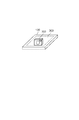
図1に示すように、実施例1に係る無線給電システムは、給電装置100と電子機器200とを有する。実施例1における無線給電システムにおいて、給電装置100における所定の範囲300内に電子機器200が存在する場合、給電装置100は、電子機器200に無線により給電を行う。また、電子機器200が所定の範囲300内に存在する場合、電子機器200は、給電装置100から出力される電力を無線により受け取ることができる。また、電子機器200が所定の範囲300内に存在しない場合、電子機器200は、給電装置100から電力を受け取ることができない。なお、所定の範囲300とは、給電装置100が電子機器200と通信を行うことができる範囲であるものとする。所定の範囲300を給電装置100の筺体上の範囲としたが、これに限られないものとする。なお、給電装置100は、複数の電子機器に対して無線により給電を行うものであってもよいものとする。   As illustrated in FIG. 1, the wireless power feeding system according to the first embodiment includes a power feeding device 100 and an electronic device 200. In the wireless power supply system according to the first embodiment, when the electronic device 200 exists within the predetermined range 300 of the power supply apparatus 100, the power supply apparatus 100 supplies power to the electronic apparatus 200 wirelessly. In addition, when the electronic device 200 exists within the predetermined range 300, the electronic device 200 can receive the power output from the power supply apparatus 100 wirelessly. Further, when the electronic device 200 does not exist within the predetermined range 300, the electronic device 200 cannot receive power from the power supply apparatus 100. Note that the predetermined range 300 is a range in which the power supply apparatus 100 can communicate with the electronic device 200. Although the predetermined range 300 is the range on the housing of the power supply apparatus 100, it is not limited to this. Note that the power supply apparatus 100 may be one that wirelessly supplies power to a plurality of electronic devices.

電子機器200は、撮像装置や再生装置であってもよく、携帯電話やスマートフォンのような通信装置であってもよいものとする。また、電子機器200は、電池を含む電池パックであってもよい。また、電子機器200は、自動車やディスプレイであってもよく、パーソナルコンピュータであってもよい。   The electronic device 200 may be an imaging device or a playback device, or may be a communication device such as a mobile phone or a smartphone. Electronic device 200 may be a battery pack including a battery. The electronic device 200 may be an automobile, a display, or a personal computer.

次に、図2を参照して、実施例1に係る給電装置100の構成の一例について説明を行う。給電装置100は、図2に示すように、制御部101、給電部102、メモリ108、表示部109、操作部110、電流検出部111、温度検出部112及び第2の通信部113を有する。給電部102には、電力生成部103、検出部104、整合回路105、第1の通信部106及び給電アンテナ107が含まれる。   Next, an example of the configuration of the power supply apparatus 100 according to the first embodiment will be described with reference to FIG. As illustrated in FIG. 2, the power supply apparatus 100 includes a control unit 101, a power supply unit 102, a memory 108, a display unit 109, an operation unit 110, a current detection unit 111, a temperature detection unit 112, and a second communication unit 113. The power supply unit 102 includes a power generation unit 103, a detection unit 104, a matching circuit 105, a first communication unit 106, and a power supply antenna 107.

制御部101は、メモリ108に記録されているコンピュータプログラムを実行することによって、給電装置100を制御する。制御部101は、例えば、CPU(Central Processing Unit)やMPU(Micro Processing Unit)を含む。なお、制御部101は、ハードウェアにより構成されるものとする。また、制御部101は、タイマー101aを有する。   The control unit 101 controls the power supply apparatus 100 by executing a computer program recorded in the memory 108. The control unit 101 includes, for example, a CPU (Central Processing Unit) and an MPU (Micro Processing Unit). Note that the control unit 101 is configured by hardware. Further, the control unit 101 includes a timer 101a.

給電部102は、所定の給電方法に基づいて、無線給電を行うために用いられる。所定の給電方法は、例えば、磁界共鳴方式を用いた給電方法である。磁界共鳴方式とは、給電装置100と電子機器200との間で共振が行われる状態において、給電装置100から電子機器200に電力を伝送するものである。給電装置100と電子機器200との間で共振が行われる状態とは、給電装置100の給電アンテナ107の共振周波数と、電子機器200の受電アンテナ203の共振周波数とが給電電力の周波数と一致している状態である。所定の給電方法は、磁界共鳴方式以外の方式を用いた給電方法であってもよい。   The power supply unit 102 is used to perform wireless power supply based on a predetermined power supply method. The predetermined power supply method is, for example, a power supply method using a magnetic field resonance method. In the magnetic field resonance method, power is transmitted from the power supply apparatus 100 to the electronic apparatus 200 in a state where resonance is performed between the power supply apparatus 100 and the electronic apparatus 200. The state where resonance is performed between the power supply apparatus 100 and the electronic device 200 is that the resonance frequency of the power supply antenna 107 of the power supply apparatus 100 and the resonance frequency of the power reception antenna 203 of the electronic device 200 match the frequency of the power supply power. It is in a state. The predetermined power supply method may be a power supply method using a method other than the magnetic field resonance method.

電力生成部103は、不図示のAC電源と給電装置100とが接続されている場合、不図示のAC電源から供給される電力を用いて、給電アンテナ107を介して外部に出力するための電力を生成する。   When the AC power supply (not shown) and the power supply apparatus 100 are connected, the power generation unit 103 uses the power supplied from the AC power supply (not shown) to output to the outside via the power supply antenna 107. Is generated.

電力生成部103によって生成される電力には、通信電力と、所定の電力とがある。通信電力は、第1の通信部106が電子機器200と通信を行うために用いられる。通信電力は、例えば、1W以下の微弱な電力であるものとする。なお、通信電力は、第1の通信部106の通信規格に規定されている電力であってもよい。所定の電力は、電子機器200が充電や特定の動作を行うために用いられる。所定の電力は、例えば、2W以上の電力であるものとする。また、所定の電力は、通信電力よりも大きい電力であれば、2W以上の電力に限られないものとする。所定の電力の値は、電子機器200から取得したデータに基づいて、制御部101によって設定される。   The power generated by the power generation unit 103 includes communication power and predetermined power. The communication power is used for the first communication unit 106 to communicate with the electronic device 200. The communication power is assumed to be weak power of 1 W or less, for example. The communication power may be power defined in the communication standard of the first communication unit 106. The predetermined power is used for the electronic device 200 to perform charging or a specific operation. The predetermined power is assumed to be 2 W or more, for example. Further, the predetermined power is not limited to 2 W or more as long as it is higher than the communication power. The predetermined power value is set by the control unit 101 based on data acquired from the electronic device 200.

電力生成部103によって生成される電力は、検出部104及び整合回路105を介して給電アンテナ107に供給される。   The power generated by the power generation unit 103 is supplied to the feeding antenna 107 via the detection unit 104 and the matching circuit 105.

検出部104は、給電装置100と電子機器200との共振の状態を検出するために、電圧定在波比VSWR(Voltage Standing Wave Ratio)を検出する。さらに、検出部104は、検出したVSWRを示すデータを制御部101に供給する。VSWRは、給電アンテナ107から出力される電力の進行波と、給電アンテナ107から出力される電力の反射波との関係を示す値である。制御部101は、検出部104から供給されたVSWRのデータを用いて、給電装置100と電子機器200との共振の状態の変化や異物の存在を検出することができる。異物とは、例えば、金属やICカード等である。なお、異物は、給電装置100の対応している給電方法に対応していない機器や電池を充電するための充電手段を有していない機器や、給電装置100と通信を行うための通信手段を有していない機器であってもよい。また、異物は、第1の通信部106の通信規格に対応していない機器であってもよい。制御部101は、検出部104で検出されたVSWRが所定値以上変化した場合、異物を検出する。   The detection unit 104 detects a voltage standing wave ratio (VSWR) in order to detect a resonance state between the power supply apparatus 100 and the electronic device 200. Further, the detection unit 104 supplies data indicating the detected VSWR to the control unit 101. The VSWR is a value indicating a relationship between a traveling wave of power output from the power feeding antenna 107 and a reflected wave of power output from the power feeding antenna 107. Using the VSWR data supplied from the detection unit 104, the control unit 101 can detect a change in the resonance state between the power supply apparatus 100 and the electronic device 200 and the presence of a foreign object. The foreign material is, for example, a metal or an IC card. Note that the foreign object may be a device that does not correspond to a power feeding method supported by the power feeding device 100, a device that does not have a charging unit for charging a battery, or a communication unit that communicates with the power feeding device 100. It may be a device that does not have. In addition, the foreign object may be a device that does not support the communication standard of the first communication unit 106. The control unit 101 detects a foreign object when the VSWR detected by the detection unit 104 changes by a predetermined value or more.

整合回路105は、給電アンテナ107の共振周波数を設定する回路と、電力生成部103と給電アンテナ107との間のインピーダンスマッチングを行うための回路とを含む。   Matching circuit 105 includes a circuit that sets a resonance frequency of power feeding antenna 107 and a circuit that performs impedance matching between power generation unit 103 and power feeding antenna 107.

給電装置100が給電アンテナ107を介して通信電力及び所定の電力のいずれか一つを出力する場合、制御部101は、給電アンテナ107の共振周波数を所定の周波数fに設定するように整合回路105を制御する。所定の周波数fは、例えば、13.56MHzである。また、所定の周波数fは、6.78MHzであってもよく、第1の通信部106の通信規格に規定されている周波数であってもよい。   When the power feeding apparatus 100 outputs any one of communication power and predetermined power via the power feeding antenna 107, the control unit 101 sets the resonance frequency of the power feeding antenna 107 to the predetermined frequency f. To control. The predetermined frequency f is, for example, 13.56 MHz. Further, the predetermined frequency f may be 6.78 MHz, or may be a frequency defined in the communication standard of the first communication unit 106.

第1の通信部106は、例えば、NFC(Near Field Communication)フォーラムによって規定されているNFC規格に基づいて、無線通信を行う。また、第1の通信部106の通信規格は、ISO/IEC 18092規格であってもよく、ISO/IEC 14443規格であってもよく、ISO/IEC 21481規格であってもよい。第1の通信部106は、通信電力が給電アンテナ107から出力されている場合、給電アンテナ107を介して電子機器200と無線給電を行うためのデータの送受信を行うことができる。しかし、所定の電力が給電アンテナ107から出力されている期間において、第1の通信部106は、給電アンテナ107を介して電子機器200と通信を行わないものとする。所定の電力が給電アンテナ107から出力されている期間を以下「所定の時間」と呼ぶ。所定の時間は、電子機器200から取得したデータに基づいて、制御部101によって設定される。   For example, the first communication unit 106 performs wireless communication based on the NFC standard defined by the NFC (Near Field Communication) forum. The communication standard of the first communication unit 106 may be the ISO / IEC 18092 standard, the ISO / IEC 14443 standard, or the ISO / IEC 21481 standard. When communication power is output from the power supply antenna 107, the first communication unit 106 can transmit and receive data for performing wireless power supply with the electronic device 200 via the power supply antenna 107. However, it is assumed that the first communication unit 106 does not communicate with the electronic device 200 via the power supply antenna 107 during a period in which predetermined power is output from the power supply antenna 107. The period during which the predetermined power is output from the feeding antenna 107 is hereinafter referred to as “predetermined time”. The predetermined time is set by the control unit 101 based on data acquired from the electronic device 200.

第1の通信部106と電子機器200との間で送受信するデータは、NDEF(NFC Data Exchange Format)に対応するデータである。   Data transmitted / received between the first communication unit 106 and the electronic device 200 is data corresponding to NDEF (NFC Data Exchange Format).

第1の通信部106は、電子機器200にNDEFに対応するデータを送信する場合、電力生成部103から供給される通信電力にデータを重畳する処理を行う。データが重畳された通信電力は、給電アンテナ107を介して電子機器200に送信される。   When transmitting data corresponding to NDEF to the electronic device 200, the first communication unit 106 performs a process of superimposing data on communication power supplied from the power generation unit 103. The communication power on which the data is superimposed is transmitted to the electronic device 200 via the power feeding antenna 107.

第1の通信部106が、電子機器200からNDEFに対応するデータを受信する場合、給電アンテナ107に流れる電流を検出し、この電流の検出結果に応じて、電子機器200からデータを受信する。これは、電子機器200が給電装置100にNDEFに対応するデータを送信する場合に、電子機器200の内部の負荷を変動させることによって、データの送信を行うからである。電子機器200の内部の負荷が変化した場合、給電アンテナ107に流れる電流を変化するので、第1の通信部106は、給電アンテナ107に流れる電流を検出することで、電子機器200からNDEFに対応するデータを受信することができる。   When the first communication unit 106 receives data corresponding to NDEF from the electronic device 200, the first communication unit 106 detects the current flowing through the power supply antenna 107, and receives data from the electronic device 200 according to the detection result of the current. This is because when the electronic device 200 transmits data corresponding to NDEF to the power supply apparatus 100, the data is transmitted by changing the internal load of the electronic device 200. When the load inside the electronic device 200 changes, the current flowing through the power supply antenna 107 changes. Therefore, the first communication unit 106 detects the current flowing through the power supply antenna 107 to cope with NDEF from the electronic device 200. Can receive data.

なお、第1の通信部106は、NFC規格に規定されているリーダライタとして動作するものとする。   Note that the first communication unit 106 operates as a reader / writer defined in the NFC standard.

給電アンテナ107は、通信電力及び所定の電力のいずれか一つを電子機器200に出力するためのアンテナである。また、給電アンテナ107は、第1の通信部106がNFC規格を用いた無線通信を電子機器200と行うために用いられる。   The power feeding antenna 107 is an antenna for outputting any one of communication power and predetermined power to the electronic device 200. The power supply antenna 107 is used for the first communication unit 106 to perform wireless communication with the electronic device 200 using the NFC standard.

メモリ108は、給電装置100を制御するためのコンピュータプログラムを記録する。さらに、メモリ108は、給電装置100の識別データ、給電装置100に関する給電パラメータや給電を制御するためのフラグ等を記録する。また、メモリ108は、電子機器200から第1の通信部106及び第2の通信部113の少なくとも一つが取得したデータを記録する。   The memory 108 records a computer program for controlling the power supply apparatus 100. Further, the memory 108 records identification data of the power supply apparatus 100, power supply parameters related to the power supply apparatus 100, a flag for controlling power supply, and the like. In addition, the memory 108 records data acquired by at least one of the first communication unit 106 and the second communication unit 113 from the electronic device 200.

表示部109は、メモリ108及び第2の通信部113から供給される映像データを表示する。   The display unit 109 displays video data supplied from the memory 108 and the second communication unit 113.

操作部110は、給電装置100を操作するためのユーザインターフェースを提供する。操作部110は、給電装置100を操作するためのボタン、スイッチやタッチパネル等を有する。制御部101は、操作部110を介して入力された入力信号に従って給電装置100を制御する。   The operation unit 110 provides a user interface for operating the power supply apparatus 100. The operation unit 110 includes buttons, switches, a touch panel, and the like for operating the power supply apparatus 100. The control unit 101 controls the power feeding apparatus 100 according to the input signal input via the operation unit 110.

電流検出部111は、給電アンテナ107に流れる電流を検出し、検出した電流を示すデータを制御部101に供給する。制御部101は、電流検出部111から供給された電流のデータを用いて、異物の存在を検出する。制御部101は、電流検出部111で検出された電流が所定の電流以上変化した場合、異物を検出する。   The current detection unit 111 detects a current flowing through the power feeding antenna 107 and supplies data indicating the detected current to the control unit 101. The control unit 101 detects the presence of a foreign substance using the current data supplied from the current detection unit 111. The control unit 101 detects a foreign object when the current detected by the current detection unit 111 changes more than a predetermined current.

温度検出部112は、給電装置100の温度を検出し、検出した温度を示すデータを制御部101に供給する。制御部101は、温度検出部112から供給された温度のデータを用いて、異物の存在を検出する。なお、温度検出部112によって検出される給電装置100の温度は、給電装置100内部の温度であってもよく、給電装置100の表面の温度であってもよい。制御部101は、温度検出部112で検出された温度が所定の温度以上変化した場合、異物を検出する。   The temperature detection unit 112 detects the temperature of the power supply apparatus 100 and supplies data indicating the detected temperature to the control unit 101. The control unit 101 detects the presence of a foreign object using the temperature data supplied from the temperature detection unit 112. Note that the temperature of the power supply apparatus 100 detected by the temperature detection unit 112 may be the temperature inside the power supply apparatus 100 or the temperature of the surface of the power supply apparatus 100. The control unit 101 detects a foreign object when the temperature detected by the temperature detection unit 112 changes by a predetermined temperature or more.

第2の通信部113は、第1の通信部106の通信規格と異なる通信規格に基づいて、電子機器200と無線通信を行う。第2の通信部113の通信規格は、例えば、無線LAN(Wireless Local Area Network)規格やBluetooth(登録商標)規格である。第2の通信部113は、給電装置100と電子機器200との間で映像データ、音声データ及びコマンドの少なくとも一つを含むデータを送信したり受信することができる。   The second communication unit 113 performs wireless communication with the electronic device 200 based on a communication standard different from the communication standard of the first communication unit 106. The communication standard of the second communication unit 113 is, for example, a wireless LAN (Wireless Local Area Network) standard or a Bluetooth (registered trademark) standard. The second communication unit 113 can transmit and receive data including at least one of video data, audio data, and commands between the power supply apparatus 100 and the electronic device 200.

給電装置100は、無線により電力を電子機器200に供給するようにした。しかし、「無線」を「非接触」や「無接点」と言い換えてもよいものとする。   The power supply apparatus 100 supplies power to the electronic device 200 wirelessly. However, “wireless” may be rephrased as “non-contact” or “non-contact”.

次に、図3を参照して、電子機器200の構成の一例について説明を行う。電子機器200は、制御部201、受電部202、電力検出部207、レギュレータ208、負荷部209、充電部210、電池211、温度検出部212、メモリ213、操作部214及び第2の通信部215を有する。受電部202には、受電アンテナ203、スイッチ(切替部)220、整合回路204、整流平滑回路205、及び第1の通信部206が含まれる。   Next, an example of the configuration of the electronic device 200 will be described with reference to FIG. The electronic device 200 includes a control unit 201, a power reception unit 202, a power detection unit 207, a regulator 208, a load unit 209, a charging unit 210, a battery 211, a temperature detection unit 212, a memory 213, an operation unit 214, and a second communication unit 215. Have The power receiving unit 202 includes a power receiving antenna 203, a switch (switching unit) 220, a matching circuit 204, a rectifying / smoothing circuit 205, and a first communication unit 206.

制御部201は、メモリ213に記録されているコンピュータプログラムを実行することによって、電子機器200を制御する。制御部201は、例えば、CPUやMPUを含む。なお、制御部201は、ハードウェアにより構成されるものとする。また、制御部201は、タイマー201aを有する。   The control unit 201 controls the electronic device 200 by executing a computer program recorded in the memory 213. The control unit 201 includes, for example, a CPU and an MPU. Note that the control unit 201 is configured by hardware. The control unit 201 has a timer 201a.

受電部202は、所定の給電方法に対応し、給電装置100から電力を無線により受け取るために用いられる。   The power receiving unit 202 corresponds to a predetermined power feeding method and is used to receive power from the power feeding apparatus 100 wirelessly.

受電アンテナ203は、給電装置100から供給される電力を受け取るためのアンテナである。また、受電アンテナ203は、第1の通信部206がNFC規格を用いた無線通信を給電装置100と行うために用いられる。受電アンテナ203を介して給電装置100から電子機器200が受け取った電力は、整合回路204を介して整流平滑回路205に供給される。   The power receiving antenna 203 is an antenna for receiving power supplied from the power feeding apparatus 100. The power receiving antenna 203 is used for the first communication unit 206 to perform wireless communication with the power supply apparatus 100 using the NFC standard. The power received by the electronic device 200 from the power feeding apparatus 100 via the power receiving antenna 203 is supplied to the rectifying / smoothing circuit 205 via the matching circuit 204.

整合回路204は、受電アンテナ203の共振周波数を設定する回路を含む。制御部201は、整合回路204を制御することによって受電アンテナ203の共振周波数を設定することができる。   The matching circuit 204 includes a circuit that sets the resonance frequency of the power receiving antenna 203. The control unit 201 can set the resonance frequency of the power receiving antenna 203 by controlling the matching circuit 204.

整流平滑回路205は、受電アンテナ203によって受電された電力から直流電力を生成する。さらに、整流平滑回路205は、生成した直流電力を電力検出部207を介してレギュレータ208に供給する。整流平滑回路205は、受電アンテナ203によって受電された電力にデータが重畳されている場合、受電アンテナ203によって受電された電力から取り除かれたデータを第1の通信部206に供給する。   The rectifying / smoothing circuit 205 generates DC power from the power received by the power receiving antenna 203. Further, the rectifying / smoothing circuit 205 supplies the generated DC power to the regulator 208 via the power detection unit 207. When the data is superimposed on the power received by the power receiving antenna 203, the rectifying / smoothing circuit 205 supplies the data removed from the power received by the power receiving antenna 203 to the first communication unit 206.

スイッチ220は、受電アンテナ203と、整合回路204、整流平滑回路205及び第1の通信部206との間を接続したり、切断するためのスイッチである。スイッチ220は、制御部201によって制御される。   The switch 220 is a switch for connecting or disconnecting the power receiving antenna 203 to the matching circuit 204, the rectifying / smoothing circuit 205, and the first communication unit 206. The switch 220 is controlled by the control unit 201.

制御部201によってスイッチ220がオンにされた場合、受電アンテナ203と、整合回路204、整流平滑回路205及び第1の通信部206との間は接続される。スイッチ220がオンである場合、受電アンテナ203によって給電装置100から受信された電力は整合回路204を介して整流平滑回路205に供給される。このため、第1の通信部206は、給電装置100からデータを受信することができ、整流平滑回路205は、給電装置100から受け取った電力から生成した直流電力をレギュレータ208に供給することができる。   When the switch 220 is turned on by the control unit 201, the power receiving antenna 203 is connected to the matching circuit 204, the rectifying / smoothing circuit 205, and the first communication unit 206. When the switch 220 is on, the power received from the power feeding device 100 by the power receiving antenna 203 is supplied to the rectifying / smoothing circuit 205 via the matching circuit 204. For this reason, the first communication unit 206 can receive data from the power supply apparatus 100, and the rectifying and smoothing circuit 205 can supply DC power generated from the power received from the power supply apparatus 100 to the regulator 208. .

制御部201によってスイッチ220がオフにされた場合、受電アンテナ203と、整合回路204、整流平滑回路205及び第1の通信部206との間は接続されない。スイッチ220がオフである場合、受電アンテナ203によって給電装置100から受信された電力は整合回路204を介して整流平滑回路205に供給されない。このため、第1の通信部206は、給電装置100からデータを受信することもできず、整流平滑回路205は、給電装置100から受け取った電力から生成した直流電力をレギュレータ208に供給することもできない。スイッチ220がオフである場合、受電アンテナ203と電池211とは接続されないので、検出部104及び電流検出部111は、電池211の残容量の変化の影響を受けずに正確な異物の検出を行うことができる。スイッチ220がオフである場合、受電アンテナ203と充電部211及び負荷部209とは接続されないので、検出部104及び電流検出部111は、電子機器200の動作の変化や負荷の変化等の影響を受けずに、正確な異物の検出を行うことができる。なお、スイッチ220がオフである場合であっても、制御部201には、電池211から放電された電力及び受電アンテナ203によって受電された電力の少なくとも一つが供給される。   When the switch 220 is turned off by the control unit 201, the power receiving antenna 203 is not connected to the matching circuit 204, the rectifying / smoothing circuit 205, and the first communication unit 206. When the switch 220 is off, the power received from the power feeding device 100 by the power receiving antenna 203 is not supplied to the rectifying / smoothing circuit 205 via the matching circuit 204. Therefore, the first communication unit 206 cannot receive data from the power supply apparatus 100, and the rectifying and smoothing circuit 205 can supply DC power generated from the power received from the power supply apparatus 100 to the regulator 208. Can not. When the switch 220 is off, the power receiving antenna 203 and the battery 211 are not connected, so that the detection unit 104 and the current detection unit 111 accurately detect a foreign object without being affected by a change in the remaining capacity of the battery 211. be able to. When the switch 220 is off, the power receiving antenna 203 is not connected to the charging unit 211 and the load unit 209, so that the detection unit 104 and the current detection unit 111 are affected by changes in the operation of the electronic device 200 and changes in the load. Without receiving it, it is possible to accurately detect foreign matter. Even when the switch 220 is off, the control unit 201 is supplied with at least one of the power discharged from the battery 211 and the power received by the power receiving antenna 203.

第1の通信部206は、第1の通信部106と同一の通信規格に基づいて、給電装置100と通信を行う。第1の通信部206は、メモリ206aを有する。メモリ206aには、WPT(Wireless Power Transfer)用RTD(Record Type Definiton)データ400が記録されている。WPT用RTDデータ400には、NDEFに対応するデータが複数格納されている。WPT用RTDデータ400には、給電装置100と電子機器200との間で無線給電を行うために必要なデータが格納される。   The first communication unit 206 communicates with the power supply apparatus 100 based on the same communication standard as the first communication unit 106. The first communication unit 206 includes a memory 206a. In the memory 206a, RTD (Record Type Definiton) data 400 for WPT (Wireless Power Transfer) is recorded. The WPT RTD data 400 stores a plurality of data corresponding to NDEF. The WPT RTD data 400 stores data necessary for wireless power feeding between the power feeding apparatus 100 and the electronic device 200.

WPT用RTDデータ400には、少なくとも無線給電の認証を給電装置100と行うために用いられる認証データが格納されている。認証データには、レコードタイプ名、電子機器200が対応している給電方法や給電の制御プロトコルを示すデータや電子機器200の識別データ、電子機器200の受電能力データ、電子機器200が持っているタグの種類を示すデータ等が含まれる。レコードタイプ名とは、WPT用RTDデータ400に格納されているデータの内容や構造を識別するためのレコードタイプ(record type)を示すデータである。レコードタイプ名(record type name)は、WPT用RTDデータ400を識別するためのデータである。受電能力データは、電子機器200の受電能力を示すデータであり、例えば、電子機器200の受電可能な電力の最大値を示す。   The WPT RTD data 400 stores at least authentication data used to perform authentication of wireless power supply with the power supply apparatus 100. The authentication data includes the record type name, data indicating the power supply method and power supply control protocol supported by the electronic device 200, identification data of the electronic device 200, power reception capability data of the electronic device 200, and the electronic device 200. Data indicating the type of tag is included. The record type name is data indicating a record type for identifying the content and structure of data stored in the RTD data 400 for WPT. The record type name (record type name) is data for identifying the RTD data 400 for WPT. The power receiving capability data is data indicating the power receiving capability of the electronic device 200, and indicates, for example, the maximum value of power that can be received by the electronic device 200.

WPT用RTDデータ400には、さらに受電ステータスデータや給電ステータスデータが格納されている。受電ステータスデータには、電子機器200の状態を示すデータが含まれる。例えば、受電ステータスデータには、給電装置100に要求する要求電力の値、電子機器200が給電装置100から受け取った電力の値、電池211の残容量や電池211の充電に関するデータ、電子機器200のエラーに関するエラーデータ等が含まれる。エラーデータには、電子機器200にエラーが発生しているか否かを示すデータと、電子機器200に発生しているエラーの種類を示すデータとが含まれる。受電ステータスデータには、電子機器200が異物検出処理をサポートしているか否かを示す情報がさらに含まれていても良い。   The WPT RTD data 400 further stores power reception status data and power supply status data. The power reception status data includes data indicating the state of the electronic device 200. For example, the power reception status data includes a value of required power requested from the power supply apparatus 100, a value of power received by the electronic device 200 from the power supply apparatus 100, data regarding the remaining capacity of the battery 211 and charging of the battery 211, Contains error data related to errors. The error data includes data indicating whether an error has occurred in the electronic device 200 and data indicating the type of error occurring in the electronic device 200. The power reception status data may further include information indicating whether or not the electronic device 200 supports foreign object detection processing.

給電ステータスデータには、給電装置100の状態を示すデータが含まれる。例えば、給電ステータスデータには、給電装置100の識別データ、給電装置100が電子機器200への所定の電力の伝送を開始するか否かを示すデータ、給電装置100で設定された給電パラメータ及び異物検出処理を行うか否かを示す情報等が含まれる。第1の通信部206は、整流平滑回路205から供給されたデータを解析する。その後、第1の通信部206は、データの解析結果を用いて、WPT用RTDデータ400から読み出したデータを給電装置100に送信したり、給電装置100から受信したデータをWPT用RTDデータ400に書き込んだりする。さらに、第1の通信部206は、整流平滑回路205から供給されたデータに対応する応答データを給電装置100に送信する。   The power supply status data includes data indicating the state of the power supply apparatus 100. For example, the power supply status data includes identification data of the power supply apparatus 100, data indicating whether the power supply apparatus 100 starts transmission of predetermined power to the electronic device 200, power supply parameters and foreign objects set by the power supply apparatus 100. Information indicating whether or not to perform detection processing is included. The first communication unit 206 analyzes the data supplied from the rectifying / smoothing circuit 205. After that, the first communication unit 206 transmits the data read from the WPT RTD data 400 to the power supply apparatus 100 using the data analysis result, and the data received from the power supply apparatus 100 to the WPT RTD data 400. Write. Further, the first communication unit 206 transmits response data corresponding to the data supplied from the rectifying and smoothing circuit 205 to the power supply apparatus 100.

第1の通信部206は、WPT用RTDデータ400から読み出したデータや応答データを給電装置100に送信するために、第1の通信部206内部の負荷を変動させる処理を行う。   The first communication unit 206 performs processing for changing the load in the first communication unit 206 in order to transmit the data read from the WPT RTD data 400 and the response data to the power supply apparatus 100.

電子機器200は、NFC規格に規定されているタグを有する。図4を参照し、電子機器200が有するタグについて説明を行う。制御部201は、不図示の内部バスインターフェースを介してWPT用RTDデータ400に格納されているデータを読み出すことができる。さらに、制御部201は、不図示の内部バスインターフェースを介してWPT用RTDデータ400にデータを書き込むことができる。   The electronic device 200 has a tag defined in the NFC standard. With reference to FIG. 4, the tag which the electronic device 200 has is demonstrated. The control unit 201 can read data stored in the WPT RTD data 400 via an internal bus interface (not shown). Furthermore, the control unit 201 can write data to the WPT RTD data 400 via an internal bus interface (not shown).

制御部201は、例えば、WPT用RTDデータ400から読み出された給電ステータスデータを用いて、電子機器200の各部を制御することができる。制御部201は、例えば、電子機器200の各部から供給されるデータを用いて受電ステータスデータを定期的に検出し、検出した受電ステータスデータをWPT用RTDデータ400に書き込むことができる。なお、電子機器200が有するタグは、「アクティブタグ」や「ダイナミックタグ」と言い換えても良いものとする。   For example, the control unit 201 can control each unit of the electronic device 200 using the power supply status data read from the RTD data 400 for WPT. For example, the control unit 201 can periodically detect power reception status data using data supplied from each unit of the electronic device 200 and write the detected power reception status data in the WPT RTD data 400. Note that the tag included in the electronic device 200 may be referred to as an “active tag” or a “dynamic tag”.

なお、給電装置100は、第1の通信部106を用いてWPT用RTDデータ400に格納されているデータを読み出すことができる。さらに、この場合、給電装置100は、第1の通信部106を用いてデータをWPT用RTDデータ400に書き込むこともできる。   The power supply apparatus 100 can read data stored in the WPT RTD data 400 using the first communication unit 106. Further, in this case, the power supply apparatus 100 can also write data into the WPT RTD data 400 using the first communication unit 106.

電力検出部207は、受電アンテナ203を介して受け取った電力を検出し、検出した電力を示すデータを制御部201に供給する。   The power detection unit 207 detects the power received via the power receiving antenna 203 and supplies data indicating the detected power to the control unit 201.

制御部201は、電力検出部207から供給された電力のデータを用いて、電子機器200に第1のエラーが発生しているか否かを判定する。第1のエラーとは、例えば、電子機器200の受電可能な電力の最大値よりも大きい電力を電子機器200が給電装置100から受け取った場合に発生するエラーである。   The control unit 201 uses the power data supplied from the power detection unit 207 to determine whether or not a first error has occurred in the electronic device 200. The first error is, for example, an error that occurs when the electronic device 200 receives power from the power supply apparatus 100 that is greater than the maximum power that can be received by the electronic device 200.

例えば、制御部201は、電子機器200の受電可能な電力の最大値と、電力検出部207で検出された電力の値とを比較し、比較の結果を用いて、電子機器200に第1のエラーが発生しているか否かを判定する。電力検出部207で検出された電力が電子機器200の受電可能な電力の最大値よりも大きい場合、制御部201は、第1のエラーが電子機器200に発生していると判定する。電力検出部207で検出された電力が電子機器200の受電可能な電力の最大値以下である場合、制御部201は、第1のエラーが電子機器200に発生していないと判定する。第1のエラーが電子機器200に発生していると判定された場合、制御部201は、電子機器200にエラーが発生していることを示すデータと、第1のエラーを示すデータとを含む受電ステータスデータをWPT用RTDデータ400に書き込む。   For example, the control unit 201 compares the maximum value of the power that can be received by the electronic device 200 with the value of the power detected by the power detection unit 207, and uses the comparison result to cause the electronic device 200 to It is determined whether an error has occurred. When the power detected by the power detection unit 207 is larger than the maximum value of power that can be received by the electronic device 200, the control unit 201 determines that the first error has occurred in the electronic device 200. When the power detected by the power detection unit 207 is less than or equal to the maximum power that can be received by the electronic device 200, the control unit 201 determines that the first error has not occurred in the electronic device 200. When it is determined that the first error has occurred in the electronic device 200, the control unit 201 includes data indicating that an error has occurred in the electronic device 200 and data indicating the first error. The power reception status data is written in the RTD data 400 for WPT.

さらに、制御部201は、電力検出部207から供給された電力のデータを用いて、電子機器200に第2のエラーが発生しているか否かを判定する。第2のエラーとは、例えば、電子機器200が給電装置100に対して要求する要求電力に対して電子機器200が給電装置100から受け取った電力が足りない場合に発生するエラーである。   Further, the control unit 201 determines whether or not a second error has occurred in the electronic device 200 using the power data supplied from the power detection unit 207. The second error is, for example, an error that occurs when the power received by the electronic device 200 from the power supply apparatus 100 is insufficient with respect to the required power that the electronic apparatus 200 requests from the power supply apparatus 100.

例えば、制御部201は、要求電力の値と、電力検出部207で検出された電力の値とを比較し、比較の結果を用いて、電子機器200に第2のエラーが発生しているか否かを判定する。   For example, the control unit 201 compares the value of the required power with the value of the power detected by the power detection unit 207, and uses the comparison result to determine whether or not the second error has occurred in the electronic device 200. Determine whether.

電力検出部207で検出された電力の値が、要求電力の値よりも小さい場合、制御部201は、第2のエラーが電子機器200に発生していると判定する。電力検出部207で検出された電力の値が、要求電力の値以上である場合、制御部201は、第2のエラーが電子機器200に発生していないと判定する。第2のエラーが電子機器200に発生していると判定された場合、制御部201は、電子機器200にエラーが発生していることを示すデータと、第2のエラーを示すデータとを含む受電ステータスデータをWPT用RTDデータ400に書き込む。   When the value of the power detected by the power detection unit 207 is smaller than the value of the required power, the control unit 201 determines that the second error has occurred in the electronic device 200. If the value of the power detected by the power detection unit 207 is equal to or greater than the value of the required power, the control unit 201 determines that the second error has not occurred in the electronic device 200. When it is determined that the second error has occurred in the electronic device 200, the control unit 201 includes data indicating that an error has occurred in the electronic device 200 and data indicating the second error. The power reception status data is written in the RTD data 400 for WPT.

レギュレータ208は、制御部201からの指示に応じて、整流平滑回路205から供給される電力及び電池211から供給される電力の少なくとも一つを電子機器200の各部に供給する。   The regulator 208 supplies at least one of the power supplied from the rectifying / smoothing circuit 205 and the power supplied from the battery 211 to each unit of the electronic device 200 in response to an instruction from the control unit 201.

負荷部209は、被写体の光学像から静止画や動画等の映像データの生成を行う撮像部や映像データの再生を行う再生部等を有する。   The load unit 209 includes an imaging unit that generates video data such as a still image and a moving image from an optical image of a subject, a playback unit that plays back video data, and the like.

充電部210は、電池211を充電する。充電部210は、制御部201からの指示に応じて、レギュレータ208から供給される電力を用いて電池211を充電するか、電池211から放電される電力をレギュレータ208に供給するかを制御する。充電部210は、定期的に電池211の残容量を検出し、電池211の残容量を示すデータや電池211の充電に関するデータを制御部201に供給する。   Charging unit 210 charges battery 211. The charging unit 210 controls whether the battery 211 is charged using the power supplied from the regulator 208 or the power discharged from the battery 211 is supplied to the regulator 208 in accordance with an instruction from the control unit 201. The charging unit 210 periodically detects the remaining capacity of the battery 211 and supplies data indicating the remaining capacity of the battery 211 and data related to charging of the battery 211 to the control unit 201.

電池211は、電子機器200に接続可能な電池である。また、電池211は、充電可能な二次電池であり、例えば、リチウムイオン電池等である。なお、電池211は、リチウムイオン電池以外のものであっても良いものとする。   The battery 211 is a battery that can be connected to the electronic device 200. The battery 211 is a rechargeable secondary battery, such as a lithium ion battery. The battery 211 may be other than a lithium ion battery.

制御部201は、電子機器200と電池211とが接続されているか否かに応じて、電子機器200に第3のエラーが発生しているか否かを判定する。第3のエラーとは、例えば、電子機器200に電池211が接続されていない場合に発生するエラーである。電子機器200と電池211とが接続されていない場合、制御部201は、電子機器200に第3のエラーが発生していると判定する。電子機器200と電池211とが接続されている場合、制御部201は、電子機器200に第3のエラーが発生していないと判定する。第3のエラーが電子機器200に発生していると判定された場合、制御部201は、電子機器200にエラーが発生していることを示すデータと、第3のエラーを示すデータとを含む受電ステータスデータをWPT用RTDデータ400に書き込む。   The control unit 201 determines whether or not a third error has occurred in the electronic device 200 according to whether or not the electronic device 200 and the battery 211 are connected. The third error is an error that occurs when the battery 211 is not connected to the electronic device 200, for example. When the electronic device 200 and the battery 211 are not connected, the control unit 201 determines that a third error has occurred in the electronic device 200. When the electronic device 200 and the battery 211 are connected, the control unit 201 determines that the third error has not occurred in the electronic device 200. When it is determined that the third error has occurred in the electronic device 200, the control unit 201 includes data indicating that an error has occurred in the electronic device 200 and data indicating the third error. The power reception status data is written in the RTD data 400 for WPT.

温度検出部212は、電子機器200の温度を検出し、検出した温度を示すデータを制御部101に供給する。制御部201は、温度検出部212から供給された温度のデータを用いて、電子機器200に第4のエラーが発生しているか否かを判定する。第4のエラーとは、例えば、電子機器200内の温度が高温になった場合に発生するエラーである。   The temperature detection unit 212 detects the temperature of the electronic device 200 and supplies data indicating the detected temperature to the control unit 101. The control unit 201 uses the temperature data supplied from the temperature detection unit 212 to determine whether or not a fourth error has occurred in the electronic device 200. The fourth error is, for example, an error that occurs when the temperature in the electronic device 200 becomes high.

制御部201は、設定値と、温度検出部212で検出された温度とを比較し、比較の結果を用いて、電子機器200に第4のエラーが発生しているか否かを判定する。設定値は、例えば、電池211の充電を正常に行うために設定されている温度の上限値である。また、設定値は、例えば、受電部202や負荷部209を保護するために設定されている温度の上限値であってもよい。温度検出部212で検出された温度が設定値よりも高い場合、制御部201は、第4のエラーが電子機器200に発生していると判定する。温度検出部212で検出された温度が設定値以下である場合、制御部201は、第4のエラーが電子機器200に発生していないと判定する。第4のエラーが電子機器200に発生していると判定された場合、制御部201は、電子機器200にエラーが発生していることを示すデータと、第4のエラーを示すデータとを含む受電ステータスデータをWPT用RTDデータ400に書き込む。   The control unit 201 compares the set value with the temperature detected by the temperature detection unit 212, and determines whether or not a fourth error has occurred in the electronic device 200 using the comparison result. The set value is, for example, an upper limit value of the temperature set for normally charging the battery 211. Further, the set value may be, for example, an upper limit value of the temperature set for protecting the power receiving unit 202 and the load unit 209. When the temperature detected by the temperature detection unit 212 is higher than the set value, the control unit 201 determines that the fourth error has occurred in the electronic device 200. When the temperature detected by the temperature detection unit 212 is equal to or lower than the set value, the control unit 201 determines that the fourth error has not occurred in the electronic device 200. When it is determined that the fourth error has occurred in the electronic device 200, the control unit 201 includes data indicating that an error has occurred in the electronic device 200 and data indicating the fourth error. The power reception status data is written in the RTD data 400 for WPT.

メモリ213は、電子機器200を制御するコンピュータプログラム及電子機器200に関するパラメータ等のデータを記憶する。   The memory 213 stores data such as a computer program for controlling the electronic device 200 and parameters related to the electronic device 200.

操作部214は、電子機器200を操作するためのユーザインターフェースを提供する。制御部201は、操作部214を介して入力された入力信号に従って電子機器200を制御する。   The operation unit 214 provides a user interface for operating the electronic device 200. The control unit 201 controls the electronic device 200 according to the input signal input via the operation unit 214.

第2の通信部215は、給電装置100と無線通信を行う。なお、第2の通信部215は、例えば、第2の通信部113と同一の通信規格に基づいて、給電装置100と無線通信を行う。   The second communication unit 215 performs wireless communication with the power supply apparatus 100. Note that the second communication unit 215 performs wireless communication with the power supply apparatus 100 based on the same communication standard as that of the second communication unit 113, for example.

(給電装置100の状態遷移図)
実施例1における給電装置100の状態の遷移について、図5を用いて説明する。図5において、状態500は、不図示のAC電源と給電装置100とが接続されている状態で、かつ、給電装置100の電源がオフである状態である。給電装置100が状態500の場合に、操作部110を用いて給電装置100の電源がオンにされたとき、給電装置100は、状態501に遷移する。
(State transition diagram of power supply apparatus 100)
The state transition of the power supply apparatus 100 according to the first embodiment will be described with reference to FIG. In FIG. 5, a state 500 is a state in which an AC power source (not shown) and the power supply apparatus 100 are connected, and the power supply of the power supply apparatus 100 is off. When the power supply apparatus 100 is in the state 500 and the power supply apparatus 100 is turned on using the operation unit 110, the power supply apparatus 100 transitions to the state 501.

状態501において、給電装置100は、WPT用RTDデータを検出する処理を行う。給電装置100が状態501である場合に、給電装置100の電源がオフにされたとき、給電装置100は、状態500に遷移する。給電装置100が状態501である場合に、給電装置100がWPT用RTDデータを検出したとき、給電装置100は、状態502に遷移する。給電装置100が無線給電のRTDを検出していない場合、給電装置100は、WPT用RTDデータ400を検出するまでは、状態501を維持する。   In the state 501, the power supply apparatus 100 performs processing for detecting RTD data for WPT. When the power supply apparatus 100 is in the state 501, when the power supply apparatus 100 is turned off, the power supply apparatus 100 transitions to the state 500. When the power supply apparatus 100 is in the state 501, when the power supply apparatus 100 detects the RTD data for WPT, the power supply apparatus 100 transitions to the state 502. When the power supply apparatus 100 has not detected the RTD for wireless power supply, the power supply apparatus 100 maintains the state 501 until the WPT RTD data 400 is detected.

状態502において、給電装置100は、検出したWPT用RTDデータを解析する処理を行う。給電装置100が状態502である場合に、WPT用RTDデータの解析の結果、給電装置100と電子機器200との無線給電の認証が成功したとき、給電装置100は、状態503に遷移する。給電装置100が状態502である場合に、無線給電に関するエラーが発生した場合、給電装置100は、状態501に遷移する。無線給電に関するエラーとは、例えば、給電装置100と電子機器200との通信に関する通信エラー、電子機器200に関するエラー、給電装置100と電子機器200との無線給電の認証に関する認証エラー等である。   In the state 502, the power supply apparatus 100 performs processing for analyzing the detected RTD data for WPT. When the power supply apparatus 100 is in the state 502, if the wireless power supply authentication between the power supply apparatus 100 and the electronic device 200 is successful as a result of the analysis of the WPT RTD data, the power supply apparatus 100 transitions to the state 503. When an error relating to wireless power feeding occurs when the power feeding apparatus 100 is in the state 502, the power feeding apparatus 100 transitions to the state 501. The error related to wireless power supply includes, for example, a communication error related to communication between the power supply device 100 and the electronic device 200, an error related to the electronic device 200, an authentication error related to authentication of wireless power supply between the power supply device 100 and the electronic device 200, and the like.

状態503において、給電装置100は、無線給電を行うために必要なステータスデータを電子機器200と交換する処理を行う。給電装置100が状態503である場合、給電装置100は、電子機器200から受電ステータスデータを受信し、電子機器200に給電ステータスデータを送信する。   In the state 503, the power supply apparatus 100 performs processing for exchanging status data necessary for wireless power supply with the electronic device 200. When the power supply apparatus 100 is in the state 503, the power supply apparatus 100 receives the power reception status data from the electronic device 200 and transmits the power supply status data to the electronic device 200.

給電装置100が状態503である場合に、ステータスデータの交換が完了し、かつ、異物検出処理を行うと判定されたとき、給電装置100は、状態504に遷移する。なお、異物検出処理については、後述する。給電装置100が状態503である場合に、ステータスデータの交換が完了し、かつ、異物検出処理を行わないと判定されたとき、給電装置100は、状態505に遷移する。   When the power supply apparatus 100 is in the state 503, when it is determined that the status data exchange has been completed and the foreign object detection process is to be performed, the power supply apparatus 100 transitions to the state 504. The foreign object detection process will be described later. When the power supply apparatus 100 is in the state 503, when it is determined that the status data exchange has been completed and the foreign object detection process is not performed, the power supply apparatus 100 transitions to the state 505.

給電装置100が状態503である場合に、無線給電に関するエラーが発生した場合、給電装置100は、状態501に遷移する。給電装置100が状態503である場合に、電子機器200の充電が完了したことが検出された場合、給電装置100は、状態501に遷移する。   When the power supply apparatus 100 is in the state 503 and an error relating to wireless power supply occurs, the power supply apparatus 100 transitions to the state 501. When it is detected that the charging of the electronic device 200 is completed when the power supply apparatus 100 is in the state 503, the power supply apparatus 100 transitions to the state 501.

状態504において、給電装置100は、異物を検出するための異物検出処理を行う。状態504において、異物検出処理が行われた後、異物が検出された場合、給電装置100は、状態503に遷移する。状態504において、異物検出処理が行われた後、異物が検出されなかった場合、給電装置100は、状態505に遷移する。なお、異物検出処理については後述する。   In the state 504, the power supply apparatus 100 performs a foreign object detection process for detecting a foreign object. If a foreign object is detected after the foreign object detection process is performed in the state 504, the power supply apparatus 100 transitions to the state 503. If no foreign object is detected after the foreign object detection process is performed in the state 504, the power supply apparatus 100 transitions to the state 505. The foreign object detection process will be described later.

状態505において、給電装置100は、所定の電力を電子機器200に供給するための給電処理を行う。給電装置100が状態504である場合に、無線給電に関するエラーが発生したとき、給電装置100は、状態504から状態503に遷移する。給電装置100が状態504である場合に、所定の電力の出力が開始されてから所定の時間が経過した後、給電装置100は、状態503に遷移する。   In the state 505, the power supply apparatus 100 performs a power supply process for supplying predetermined power to the electronic device 200. When the power supply apparatus 100 is in the state 504 and an error related to wireless power supply occurs, the power supply apparatus 100 transitions from the state 504 to the state 503. When the power supply apparatus 100 is in the state 504, the power supply apparatus 100 transitions to the state 503 after a predetermined time has elapsed since the start of output of predetermined power.

(制御処理)
次に、実施例1において、給電装置100の無線給電を制御するための制御処理について、図6のフローチャートを用いて説明する。制御処理は、制御部101がメモリ108に格納されているコンピュータプログラムを実行することにより実現することができる。
(Control processing)
Next, control processing for controlling wireless power feeding of the power feeding apparatus 100 in the first embodiment will be described with reference to the flowchart of FIG. The control process can be realized by the control unit 101 executing a computer program stored in the memory 108.

S601において、制御部101は、給電装置100の電源がオンであるか否かを検出する。給電装置100の電源がオンであることが検出された場合(S601でYes)、本フローチャートは、S602に進む。給電装置100の電源がオンでないことが検出された場合(S601でNo)、本フローチャートは終了する。   In step S <b> 601, the control unit 101 detects whether the power supply apparatus 100 is turned on. When it is detected that the power supply device 100 is powered on (Yes in S601), the flowchart proceeds to S602. If it is detected that the power supply apparatus 100 is not turned on (No in S601), the flowchart ends.

S602において、制御部101は、後述の認証処理を行う。認証処理が行われた場合、本フローチャートは、S603に進む。   In step S602, the control unit 101 performs an authentication process described later. When the authentication process is performed, the flowchart proceeds to S603.

S603において、制御部101は、給電装置100と電子機器200との無線給電の認証が成功したか否かを判定する。S602で認証処理が行われた場合、メモリ108に認証成功フラグ及び認証失敗フラグのいずれか一つが設定される。メモリ108に認証成功フラグが設定されている場合、制御部101は、無線給電の認証が成功したと判定し(S603でYes)、本フローチャートはS604に進む。メモリ108に認証失敗フラグが設定されている場合、制御部101は、無線給電の認証が失敗したと判定し(S603でNo)、本フローチャートはS608に進む。   In step S <b> 603, the control unit 101 determines whether the wireless power supply authentication between the power supply apparatus 100 and the electronic device 200 has been successful. When the authentication process is performed in S602, either one of the authentication success flag and the authentication failure flag is set in the memory 108. When the authentication success flag is set in the memory 108, the control unit 101 determines that the wireless power supply authentication is successful (Yes in S603), and the process proceeds to S604. If the authentication failure flag is set in the memory 108, the control unit 101 determines that the wireless power supply authentication has failed (No in S603), and the process proceeds to S608.

S604において、制御部101は、後述のステータスデータ交換処理を行う。ステータスデータ交換処理が行われた場合、本フローチャートは、S605に進む。   In step S604, the control unit 101 performs status data exchange processing described later. If the status data exchange process has been performed, the process proceeds to S605.

S605において、制御部101は、給電装置100が電子機器200への給電を行うことができるか否かを判定する。S604でステータスデータ交換処理が行われた場合、メモリ108に給電可能フラグ及び給電不可フラグのいずれか一つが設定される。メモリ108に給電可能フラグが設定されている場合、制御部101は、給電装置100が電子機器200への給電を行うことができると判定し(S605でYes)、本フローチャートはS606に進む。メモリ108に給電不可フラグが設定されている場合、制御部101は、給電装置100が電子機器200への給電を行うことができないと判定し(S605でNo)、本フローチャートはS608に進む。   In step S <b> 605, the control unit 101 determines whether the power supply apparatus 100 can supply power to the electronic device 200. When the status data exchange process is performed in S604, either one of the power supply enable flag and the power supply disable flag is set in the memory 108. When the power supply enable flag is set in the memory 108, the control unit 101 determines that the power supply apparatus 100 can supply power to the electronic device 200 (Yes in S605), and the process proceeds to S606. If the power supply disable flag is set in the memory 108, the control unit 101 determines that the power supply apparatus 100 cannot supply power to the electronic device 200 (No in S605), and the process proceeds to S608.

S606において、制御部101は、後述の給電処理を行う。給電処理が行われた場合、本フローチャートは、S607に進む。   In step S606, the control unit 101 performs power supply processing described later. When the power supply process is performed, the flowchart proceeds to S607.

S607において、制御部101は、給電装置100が電子機器200への給電を継続して行うか否かを判定する。S606で給電処理が行われた場合、メモリ108に給電継続フラグ及び給電停止フラグのいずれか一つが設定される。メモリ108に給電継続フラグが設定されている場合、制御部101は、給電装置100が電子機器200への給電を継続して行うと判定し(S607でYes)、本フローチャートはS604に戻る。メモリ108に給電停止フラグが設定されている場合、制御部101は、給電装置100が電子機器200への給電を継続して行わないと判定し(S607でNo)、本フローチャートはS608に進む。   In step S <b> 607, the control unit 101 determines whether the power supply apparatus 100 continues to supply power to the electronic device 200. When the power supply process is performed in S606, one of the power supply continuation flag and the power supply stop flag is set in the memory 108. When the power supply continuation flag is set in the memory 108, the control unit 101 determines that the power supply apparatus 100 continues to supply power to the electronic device 200 (Yes in S607), and the flowchart returns to S604. If the power supply stop flag is set in the memory 108, the control unit 101 determines that the power supply apparatus 100 does not continue to supply power to the electronic device 200 (No in S607), and the process proceeds to S608.

S608において、制御部101は、メモリ108に格納されている給電パラメータや給電の制御に関するフラグ等を消去する。この場合、本フローチャートは、S601に戻る。   In step S <b> 608, the control unit 101 deletes the power supply parameters stored in the memory 108, flags related to power supply control, and the like. In this case, the flowchart returns to S601.

(認証処理)
次に、実施例1において、図6のS602において、制御部101によって行われる認証処理について、図7のフローチャートを用いて説明する。認証処理は、制御部101がメモリ108に格納されているコンピュータプログラムを実行することにより実現することができる。
(Authentication process)
Next, in the first embodiment, the authentication process performed by the control unit 101 in S602 of FIG. 6 will be described using the flowchart of FIG. The authentication process can be realized by the control unit 101 executing a computer program stored in the memory 108.

S701において、制御部101は、通信電力を出力するように給電部102を制御する。なお、制御部101は、所定の電力を出力する処理を開始するまで、通信電力が給電アンテナ107を介して出力されるようにする。この場合、本フローチャートは、S702に進む。   In step S701, the control unit 101 controls the power supply unit 102 to output communication power. Note that the control unit 101 causes the communication power to be output via the feeding antenna 107 until a process of outputting predetermined power is started. In this case, the flowchart proceeds to S702.

S702において、制御部101は、認証データを要求するデータを送信するように第1の通信部106を制御する。この場合、本フローチャートは、S703に進む。   In step S <b> 702, the control unit 101 controls the first communication unit 106 to transmit data requesting authentication data. In this case, the flowchart proceeds to S703.

S703において、制御部101は、WPT用RTDデータ400を検出したか否かを判定する。第1の通信部106が電子機器200から認証データを受信した場合、制御部101は、電子機器200の認証データから電子機器200のレコードタイプ名を取得する。その後、制御部101は、電子機器200のレコードタイプ名に基づいて、WPT用RTDデータ400を検出したか否かを判定する。WPT用RTDデータ400が検出された場合(S703でYes)、本フローチャートはS704に進む。WPT用RTDデータ400が検出されていない場合(S703でNo)、本フローチャートはS702に戻る。なお、第1の通信部106が電子機器200から認証データを受信していない場合も、本フローチャートはS702に戻る。   In step S <b> 703, the control unit 101 determines whether the WPT RTD data 400 has been detected. When the first communication unit 106 receives the authentication data from the electronic device 200, the control unit 101 acquires the record type name of the electronic device 200 from the authentication data of the electronic device 200. Thereafter, the control unit 101 determines whether or not the WPT RTD data 400 has been detected based on the record type name of the electronic device 200. When the WPT RTD data 400 is detected (Yes in S703), the process proceeds to S704. When the WPT RTD data 400 is not detected (No in S703), the process returns to S702. Note that even when the first communication unit 106 has not received the authentication data from the electronic device 200, the flowchart returns to S702.

S704において、制御部101は、電子機器200の認証データに含まれるデータを確認することで、電子機器200のWPT用RTDデータ400を解析する。この場合、本フローチャートはS705に進む。   In step S <b> 704, the control unit 101 analyzes the WPT RTD data 400 of the electronic device 200 by confirming data included in the authentication data of the electronic device 200. In this case, the flowchart proceeds to S705.

S705において、制御部101は、S704の解析結果を用いて、電子機器200の認証データに通信エラーが発生しているか否かを検出する。電子機器200の認証データに通信エラーが検出された場合(S705でYes)、本フローチャートは、S706に進む。電子機器200の認証データに通信エラーが検出されていない場合(S705でNo)、本フローチャートは、S708に進む。   In step S <b> 705, the control unit 101 detects whether a communication error has occurred in the authentication data of the electronic device 200 using the analysis result in step S <b> 704. When a communication error is detected in the authentication data of the electronic device 200 (Yes in S705), the flowchart proceeds to S706. When a communication error is not detected in the authentication data of the electronic device 200 (No in S705), the flowchart proceeds to S708.

S706において、制御部101は、給電装置100と電子機器200との間における通信のエラーが検出されたことを示すデータを表示部109に表示させる。この場合、本フローチャートは、S707に進む。   In step S <b> 706, the control unit 101 causes the display unit 109 to display data indicating that a communication error between the power supply apparatus 100 and the electronic device 200 has been detected. In this case, the flowchart proceeds to S707.

S707において、制御部101は、メモリ108に認証失敗フラグを設定する。この場合、本フローチャートは終了し、図6のS603に進む。   In step S <b> 707, the control unit 101 sets an authentication failure flag in the memory 108. In this case, the flowchart ends, and the process proceeds to S603 in FIG.

S708において、制御部101は、S704の解析結果を用いて、電子機器200が給電装置100に対応しているか否かを判定する。   In step S <b> 708, the control unit 101 determines whether the electronic device 200 is compatible with the power supply apparatus 100 using the analysis result in step S <b> 704.

例えば、制御部101は、給電装置100が対応している給電方法と電子機器200が対応している給電方法とが一致している場合、電子機器200が給電装置100に対応していると判定する。また、制御部101は、給電装置100が対応している給電方法と電子機器200が対応している給電方法とが一致していない場合、電子機器200が給電装置100に対応していないと判定する。   For example, the control unit 101 determines that the electronic device 200 is compatible with the power supply device 100 when the power supply method supported by the power supply device 100 matches the power supply method supported by the electronic device 200. To do. The control unit 101 determines that the electronic device 200 is not compatible with the power supply device 100 when the power supply method supported by the power supply device 100 and the power supply method supported by the electronic device 200 do not match. To do.

また、例えば、制御部101は、給電装置100が対応している給電の制御プロトコルと電子機器200が対応している給電の制御プロトコルとが一致している場合、電子機器200が給電装置100に対応していると判定する。また、給電装置100が対応している給電の制御プロトコルと電子機器200が対応している給電の制御プロトコルとが一致していない場合、電子機器200が給電装置100に対応していないと判定する。   For example, when the power supply control protocol supported by the power supply apparatus 100 matches the power supply control protocol supported by the electronic apparatus 200, the control unit 101 causes the electronic apparatus 200 to become the power supply apparatus 100. Judge that it corresponds. If the power supply control protocol supported by the power supply apparatus 100 does not match the power supply control protocol supported by the electronic apparatus 200, it is determined that the electronic apparatus 200 does not support the power supply apparatus 100. .

電子機器200が給電装置100に対応していない場合(S708でNo)、本フローチャートは、S709に進む。電子機器200が給電装置100に対応している場合(S708でYes)、本フローチャートは、S710に進む。   When the electronic device 200 does not support the power supply apparatus 100 (No in S708), the flowchart proceeds to S709. When the electronic device 200 is compatible with the power supply apparatus 100 (Yes in S708), the flowchart proceeds to S710.

S709において、制御部101は、給電装置100と電子機器200との間における認証のエラーが検出されたことを示すデータを表示部109に表示させる。この場合、本フローチャートは、S707に進む。   In step S <b> 709, the control unit 101 causes the display unit 109 to display data indicating that an authentication error between the power supply apparatus 100 and the electronic device 200 has been detected. In this case, the flowchart proceeds to S707.

S710において、制御部101は、メモリ108に認証成功フラグを設定する。この場合、本フローチャートは終了し、図6のS603に進む。   In step S <b> 710, the control unit 101 sets an authentication success flag in the memory 108. In this case, the flowchart ends, and the process proceeds to S603 in FIG.

なお、S701とS702の間に、制御部101は、NFC規格のNFCデジタルプロトコル(NFC Digital Protocol)において規定されている処理を行ってもよい。   In addition, between S701 and S702, the control part 101 may perform the process prescribed | regulated in the NFC digital protocol (NFC Digital Protocol) of a NFC standard.

(ステータスデータ交換処理)
次に、実施例1において、図6のS604において、制御部101によって行われるステータスデータ交換処理について、図8のフローチャートを用いて説明する。ステータスデータ交換処理は、制御部101がメモリ108に格納されているコンピュータプログラムを実行することにより実現することができる。
(Status data exchange process)
Next, in Example 1, the status data exchange process performed by the control unit 101 in S604 of FIG. 6 will be described with reference to the flowchart of FIG. The status data exchange process can be realized by the control unit 101 executing a computer program stored in the memory 108.

S801において、制御部101は、受電ステータスデータを要求するデータを送信するように第1の通信部106を制御する。この場合、本フローチャートは、S802に進む。   In step S801, the control unit 101 controls the first communication unit 106 to transmit data requesting power reception status data. In this case, in the flowchart, the process proceeds to S802.

S802において、制御部101は、電子機器200に受電ステータスデータの要求が行われてから一定の時間が経過するまでの間に、第1の通信部106が電子機器200から受電ステータスデータを受信したか否かを判定する。第1の通信部106が電子機器200から受電ステータスデータを受信したと判定された場合(S802でYes)、本フローチャートは、S805に進む。受電ステータスデータの要求が行われてから一定の時間が経過した場合であっても、第1の通信部106が電子機器200から受電ステータスデータを受信していないと判定された場合(S802でNo)、本フローチャートは、S803に進む。   In step S <b> 802, the control unit 101 receives the power reception status data from the electronic device 200 until a predetermined time elapses after the electronic device 200 requests power reception status data. It is determined whether or not. When it is determined that the first communication unit 106 has received power reception status data from the electronic device 200 (Yes in S802), the flowchart proceeds to S805. Even when a predetermined time has elapsed since the request for the power reception status data has been made, if it is determined that the first communication unit 106 has not received the power reception status data from the electronic device 200 (No in S802) ) In this flowchart, the process proceeds to S803.

S803において、制御部101は、S706と同様に、通信のエラーが検出されたことを示すデータを表示部109に表示させる。この場合、本フローチャートは、S804に進む。   In step S803, the control unit 101 causes the display unit 109 to display data indicating that a communication error has been detected, as in step S706. In this case, the flowchart proceeds to S804.

S804において、制御部101は、メモリ108に給電不可フラグを設定する。この場合、本フローチャートは終了し、図6のS605に進む。   In step S <b> 804, the control unit 101 sets a power supply impossible flag in the memory 108. In this case, this flowchart ends, and the process proceeds to S605 in FIG.

S805において、制御部101は、第1の通信部106が受信した受電ステータスデータを用いて、電子機器200の充電が完了したか否かを判定する。電子機器200の充電が完了したと判定された場合(S805でYes)、本フローチャートは、S806に進む。電子機器200の充電が完了していないと判定された場合(S805でNo)、本フローチャートは、S807に進む。   In step S <b> 805, the control unit 101 determines whether charging of the electronic device 200 has been completed using the power reception status data received by the first communication unit 106. If it is determined that charging of the electronic device 200 has been completed (Yes in S805), the flowchart proceeds to S806. When it is determined that charging of the electronic device 200 has not been completed (No in S805), the flowchart proceeds to S807.

S806において、制御部101は、電子機器200の充電が完了したことを示すデータを表示部109に表示させる。また、制御部101は、電池211が満充電であることを示すデータを表示部109に表示させてもよい。この場合、本フローチャートは、S804に進む。   In step S806, the control unit 101 causes the display unit 109 to display data indicating that charging of the electronic device 200 has been completed. Further, the control unit 101 may cause the display unit 109 to display data indicating that the battery 211 is fully charged. In this case, the flowchart proceeds to S804.

S807において、制御部101は、第1の通信部106が受信した受電ステータスデータを用いて、電子機器200にエラーが発生しているか否かを判定する。例えば、制御部101は、電子機器200の受電ステータスデータからエラーデータを検出し、エラーデータを解析することで、電子機器200にエラーが発生しているか否かを判定する。   In step S <b> 807, the control unit 101 determines whether an error has occurred in the electronic device 200 using the power reception status data received by the first communication unit 106. For example, the control unit 101 determines whether or not an error has occurred in the electronic device 200 by detecting error data from the power reception status data of the electronic device 200 and analyzing the error data.

電子機器200にエラーが発生していると判定された場合(S807でYes)、本フローチャートは、S808に進む。電子機器200にエラーが発生していないと判定された場合(S807でNo)、本フローチャートは、S809に進む。   If it is determined that an error has occurred in the electronic device 200 (Yes in S807), the flowchart proceeds to S808. When it is determined that no error has occurred in the electronic device 200 (No in S807), the flowchart proceeds to S809.

S808において、制御部101は、電子機器200にエラーが発生したことを示すデータを表示部109に表示させる。さらに、制御部101は、電子機器200に発生したエラーの種類を示すデータを表示部109に表示させてもよい。   In step S808, the control unit 101 causes the display unit 109 to display data indicating that an error has occurred in the electronic device 200. Further, the control unit 101 may cause the display unit 109 to display data indicating the type of error that has occurred in the electronic device 200.

この場合、本フローチャートは、S804に進む。   In this case, the flowchart proceeds to S804.

S809において、制御部101は、第1の通信部106が受信した受電ステータスデータを用いて、給電パラメータを設定する。給電パラメータとは、所定の電力の値及び所定の時間である。例えば、制御部101は、電子機器200から要求されている電力と、給電装置100から電子機器200への給電効率に基づいて、所定の電力の値及び所定の時間を設定する。給電装置100から電子機器200への給電効率とは、給電装置100が出力する電力に対して電子機器200が受け取る電力の割合を示す。また、例えば、制御部101は、電池211の残容量に基づいて、所定の電力の値及び所定の時間を設定してもよい。制御部101は、設定した給電パラメータをメモリ108に格納する。この場合、本フローチャートは、S810に進む。   In step S <b> 809, the control unit 101 sets power supply parameters using the power reception status data received by the first communication unit 106. The power supply parameter is a predetermined power value and a predetermined time. For example, the control unit 101 sets a predetermined power value and a predetermined time based on the power requested from the electronic device 200 and the power supply efficiency from the power supply apparatus 100 to the electronic device 200. The power supply efficiency from the power supply apparatus 100 to the electronic device 200 indicates the ratio of the power received by the electronic device 200 to the power output from the power supply apparatus 100. For example, the control unit 101 may set a predetermined power value and a predetermined time based on the remaining capacity of the battery 211. The control unit 101 stores the set power supply parameter in the memory 108. In this case, the flowchart proceeds to S810.

S810において、制御部101は、異物検出処理を行う必要があるか否かを判定する。異物検出処理を行う必要があると判定された場合(S810でYes)、本フローチャートは、S811に進む。異物検出処理を行う必要がないと判定された場合(S810でNo)、本フローチャートは、S816に進む。   In step S810, the control unit 101 determines whether it is necessary to perform foreign object detection processing. If it is determined that the foreign object detection process needs to be performed (Yes in S810), the process proceeds to S811. If it is determined that it is not necessary to perform the foreign object detection process (No in S810), the flowchart proceeds to S816.

例えば、制御部101は、S809において設定された所定の電力の大きさに応じて、異物検出処理を行う必要があるか否かを判定する。S809において設定された所定の電力が第1の値よりも大きい場合、制御部101は、異物検出処理を行う必要があると判定する。これは、S809において設定された所定の電力が第1の値よりも大きい場合、給電アンテナ107から出力される所定の電力が異物に影響を与える可能性があるからである。また、S809において設定された所定の電力が第1の値以下である場合、制御部101は、異物検出処理を行う必要はないと判定する。これは、S809において設定された所定の電力が第1の値以下である場合、給電アンテナ107から出力される所定の電力による異物への影響が小さいからである。第1の値とは、例えば、1Wであるものとする。しかしながら、第1の値は、1Wに限られず、異物に影響を与えると予測される電力の大きさに応じて設定されるものであれば良い。   For example, the control unit 101 determines whether or not it is necessary to perform foreign object detection processing according to the predetermined power level set in S809. When the predetermined power set in S809 is larger than the first value, the control unit 101 determines that the foreign object detection process needs to be performed. This is because if the predetermined power set in S809 is larger than the first value, the predetermined power output from the power feeding antenna 107 may affect the foreign object. When the predetermined power set in S809 is equal to or less than the first value, the control unit 101 determines that it is not necessary to perform the foreign object detection process. This is because when the predetermined power set in S809 is less than or equal to the first value, the influence of the predetermined power output from the feeding antenna 107 on the foreign object is small. The first value is assumed to be 1 W, for example. However, the first value is not limited to 1 W, and may be set according to the magnitude of power predicted to affect the foreign object.

また、例えば、制御部101は、S809において設定された所定の時間の長さに応じて、異物検出処理を行う必要があるか否かを判定する。S809において設定された所定の時間が第2の値以上である場合、制御部101は、異物検出処理を行う必要があると判定する。これは、S809において設定された所定の時間が第2の値以上である場合、所定の時間が経過するまでの間に給電アンテナ107から出力される所定の電力が異物に影響を与える可能性があるからである。また、S809において設定された所定の時間が第2の値以上でない場合、制御部101は、異物検出処理を行う必要はないと判定する。これは、S809において設定された所定の時間が第2の値以上でない場合、所定の時間が経過するまでの間に給電アンテナ107から出力される所定の電力による異物への影響が小さいからである。第2の値とは、例えば、60秒であるものとする。しかしながら、第2の値は、60秒に限られず、異物に影響を与えると予測される給電の時間の長さに応じて設定されるものであれば良い。   Further, for example, the control unit 101 determines whether or not the foreign object detection process needs to be performed according to the predetermined time length set in S809. When the predetermined time set in S809 is equal to or greater than the second value, the control unit 101 determines that it is necessary to perform foreign object detection processing. This is because if the predetermined time set in S809 is equal to or greater than the second value, the predetermined power output from the power feeding antenna 107 before the predetermined time elapses may affect the foreign object. Because there is. If the predetermined time set in S809 is not equal to or greater than the second value, the control unit 101 determines that it is not necessary to perform the foreign object detection process. This is because, when the predetermined time set in S809 is not equal to or greater than the second value, the influence of the predetermined power output from the feeding antenna 107 on the foreign object is small before the predetermined time elapses. . The second value is, for example, 60 seconds. However, the second value is not limited to 60 seconds, and may be set according to the length of time of power supply that is predicted to affect the foreign matter.

また、例えば、制御部101は、S802において電子機器200から取得された受電ステータスデータから電池211の残容量を検出し、電池211の残容量に応じて、異物検出処理を行う必要があるか否かを判定する。電池211の残容量が第3の値以上である場合、制御部101は、異物検出処理を行う必要はないと判定する。これは、電池211の残容量が第3の値以上である場合、所定の時間が短くなり、所定の電力の大きさが小さくなるので、給電アンテナ107から出力される電力による異物への影響が小さいからである。また、電池211の残容量が第3の値以上でない場合、制御部101は、異物検出処理を行う必要があると判定する。これは、電池211の残容量が第3の値以上でない場合、所定の時間が長くなり、所定の電力が大きくなるので、給電アンテナ107から出力される電力が異物に影響を与える可能性があるからである。第3の値とは、例えば、電池211の総容量の90%の容量に対応する値であるものとする。しかしながら、第3の値は、電池211の総容量の90%の容量に対応する値に限られないものとする。   In addition, for example, the control unit 101 detects the remaining capacity of the battery 211 from the power reception status data acquired from the electronic device 200 in step S <b> 802, and whether or not it is necessary to perform foreign object detection processing according to the remaining capacity of the battery 211. Determine whether. When the remaining capacity of the battery 211 is greater than or equal to the third value, the control unit 101 determines that it is not necessary to perform foreign object detection processing. This is because when the remaining capacity of the battery 211 is equal to or greater than the third value, the predetermined time is shortened and the predetermined power is reduced, so that the power output from the power supply antenna 107 has an effect on the foreign matter. Because it is small. Further, when the remaining capacity of the battery 211 is not equal to or greater than the third value, the control unit 101 determines that it is necessary to perform a foreign object detection process. This is because, when the remaining capacity of the battery 211 is not greater than or equal to the third value, the predetermined time becomes longer and the predetermined power increases, so that the power output from the power feeding antenna 107 may affect the foreign matter. Because. The third value is assumed to be a value corresponding to a capacity of 90% of the total capacity of the battery 211, for example. However, the third value is not limited to a value corresponding to a capacity of 90% of the total capacity of the battery 211.

また、制御部101は、S802において電子機器200から取得された受電ステータスデータから電子機器200からの要求電力を検出し、要求電力が増加したか否かに応じて、異物検出処理を行う必要があるか否かを判定する。要求電力が増加した場合、制御部101は、異物検出処理を行う必要があると判定する。これは、要求電力が増加した場合、給電アンテナ107から出力される所定の電力の大きさが大きくなることによって異物への影響が大きくなるからである。また、要求電力が増加していない場合、制御部101は、異物検出処理を行う必要はないと判定する。これは、要求電力が増加していない場合、給電アンテナ107から出力される所定の電力による異物への影響は大きくならないからである。しかしながら、要求電力が増加した場合であっても、要求電力の増加分が第4の値以上でない場合、制御部101は、異物検出処理を行う必要はないと判定しても良い。この場合、要求電力の増加分が第4の値以上である場合、制御部101は、異物検出処理を行う必要があると判定する。なお、第4の値は、1Wであるものとする。しかしながら、第4の値は、1Wに限られず、異物に影響を与えると予測される電力の大きさに応じて設定されるものであれば良い。   In addition, the control unit 101 needs to detect the required power from the electronic device 200 from the power reception status data acquired from the electronic device 200 in S802, and perform a foreign object detection process depending on whether the required power has increased. It is determined whether or not there is. When the required power increases, the control unit 101 determines that it is necessary to perform foreign object detection processing. This is because when the required power is increased, the influence of the foreign matter is increased by increasing the magnitude of the predetermined power output from the feeding antenna 107. When the required power has not increased, the control unit 101 determines that it is not necessary to perform the foreign object detection process. This is because when the required power has not increased, the influence of the predetermined power output from the feeding antenna 107 on the foreign matter does not increase. However, even if the required power increases, if the increase in the required power is not equal to or greater than the fourth value, the control unit 101 may determine that it is not necessary to perform the foreign object detection process. In this case, when the increase in the required power is equal to or greater than the fourth value, the control unit 101 determines that the foreign object detection process needs to be performed. Note that the fourth value is 1 W. However, the fourth value is not limited to 1 W, and may be any value that is set according to the magnitude of power that is predicted to affect the foreign object.

S811において、制御部101は、メモリ108に異物検出処理実行フラグを設定する。この場合、本フローチャートはS812に進む。   In step S811, the control unit 101 sets a foreign object detection process execution flag in the memory 108. In this case, the flowchart proceeds to S812.

S812において、制御部101は、異物検出処理を行うことを示す情報及びS809で設定された給電パラメータを含む給電ステータスデータを第1の通信部106を制御する。この場合、本フローチャートは、S813に進む。なお、異物検出処理を行うことを示す情報には、異物の検出方法を示す情報及び検出時間を示す情報が含まれる。なお、検出時間とは、異物検出処理が行われる時間である。異物の検出方法を示す情報には、例えば、VSWRを使って異物を検出することを示す情報、給電アンテナ107に流れる電流を使って異物を検出することを示す情報及び給電装置100の温度を使って異物を検出することを示す情報の少なくとも一つが含まれる。   In step S812, the control unit 101 controls the first communication unit 106 with power supply status data including information indicating that foreign object detection processing is performed and the power supply parameter set in step S809. In this case, in the flowchart, the process proceeds to S813. The information indicating that the foreign object detection process is performed includes information indicating a foreign object detection method and information indicating a detection time. Note that the detection time is a time during which foreign object detection processing is performed. The information indicating the foreign object detection method includes, for example, information indicating that the foreign object is detected using the VSWR, information indicating that the foreign object is detected using the current flowing through the power supply antenna 107, and the temperature of the power supply apparatus 100. At least one piece of information indicating that a foreign object is detected.

S813において、制御部101は、第1の通信部106によって電子機器200から応答データが受信されたか否かを判定する。第1の通信部106によって電子機器200から応答データが受信されていない場合(S813でNo)、本フローチャートは、S814に進む。第1の通信部106によって電子機器200から応答データが受信された場合(S813でYes)、本フローチャートは、S815に進む。S814において、制御部101は、S803と同様に、通信のエラーが検出されたことを示すデータを表示部109に表示させる。この場合、本フローチャートは、S804に進む。   In step S813, the control unit 101 determines whether response data has been received from the electronic device 200 by the first communication unit 106. When response data is not received from the electronic device 200 by the first communication unit 106 (No in S813), the process proceeds to S814. When response data is received from the electronic device 200 by the first communication unit 106 (Yes in S813), the flowchart proceeds to S815. In step S814, the control unit 101 causes the display unit 109 to display data indicating that a communication error has been detected, as in step S803. In this case, the flowchart proceeds to S804.

S815において、制御部101は、メモリ108に給電可能フラグを設定する。この場合、本フローチャートは終了し、図6のS605に進む。   In step S <b> 815, the control unit 101 sets a power supply enable flag in the memory 108. In this case, this flowchart ends, and the process proceeds to S605 in FIG.

S816において、制御部101は、メモリ108に異物検出処理実行フラグをリセットする。この場合、本フローチャートはS817に進む。   In step S816, the control unit 101 resets the foreign object detection processing execution flag in the memory 108. In this case, the flowchart proceeds to S817.

S817において、制御部101は、異物検出処理を行わないことを示す情報及びS809で設定された給電パラメータを含む給電ステータスデータを第1の通信部106を制御する。この場合、本フローチャートは、S813に進む。   In step S817, the control unit 101 controls the first communication unit 106 with power supply status data including information indicating that the foreign object detection processing is not performed and the power supply parameter set in step S809. In this case, in the flowchart, the process proceeds to S813.

給電装置100から異物検出処理を行うことを示す給電ステータスデータを電子機器200が受信した場合に、第1の通信部206は、電子機器200が異物検出処理に対応している否かに応じて、応答データを給電装置100に送信する。異物検出処理を行うことを示す給電ステータスデータに含まれる異物検出方法を電子機器200がサポートしている場合、第1の通信部206は、異物検出処理をサポートしていることを示す情報を給電装置100に送信する。異物検出処理を行うことを示す給電ステータスデータに含まれる異物検出方法を電子機器200がサポートしていない場合、第1の通信部206は、異物検出処理をサポートしていないことを示す情報を給電装置100に送信する。給電装置100は、異物検出処理を行うことを示す給電ステータスデータを電子機器200に送信した後、異物検出処理をサポートしていないことを示す情報を電子機器200から受信した場合、S815の処理を行うことなく、S804の処理を行うようにする。給電装置100は、異物検出処理を行うことを示す給電ステータスデータを電子機器200に送信した後、異物検出処理をサポートしていることを示す情報を電子機器200から受信した場合、S815の処理を行う。   When the electronic device 200 receives power supply status data indicating that foreign object detection processing is to be performed from the power supply apparatus 100, the first communication unit 206 determines whether or not the electronic device 200 supports the foreign object detection processing. The response data is transmitted to the power supply apparatus 100. When the electronic device 200 supports the foreign object detection method included in the power supply status data indicating that the foreign object detection process is performed, the first communication unit 206 supplies information indicating that the foreign object detection process is supported. Transmit to device 100. When the electronic device 200 does not support the foreign object detection method included in the power supply status data indicating that the foreign object detection process is performed, the first communication unit 206 supplies information indicating that the foreign object detection process is not supported. Transmit to device 100. The power supply apparatus 100 transmits the power supply status data indicating that the foreign object detection process is performed to the electronic device 200, and then receives information indicating that the foreign object detection process is not supported from the electronic device 200, the process of S815 is performed. The process of S804 is performed without performing it. The power supply apparatus 100 transmits the power supply status data indicating that the foreign object detection process is performed to the electronic device 200, and then receives information indicating that the foreign object detection process is supported from the electronic device 200, the process of S815 is performed. Do.

(給電処理)
次に、実施例1において、図6のS606において、制御部101によって行われる給電処理について、図9のフローチャートを用いて説明する。給電処理は、制御部101がメモリ108に格納されているコンピュータプログラムを実行することにより実現することができる。
(Power supply processing)
Next, in Embodiment 1, the power supply process performed by the control unit 101 in S606 of FIG. 6 will be described using the flowchart of FIG. The power supply process can be realized by the control unit 101 executing a computer program stored in the memory 108.

S901において、制御部101は、メモリ108に異物検出処理実行フラグが設定されているか否かによって、異物検出処理を行うか否かを判定する。メモリ108に格納されている異物検出処理実行フラグが設定されている場合(S901でYes)、制御部101は、異物検出処理を行うと判定する。この場合、本フローチャートは、S902に進む。メモリ108に格納されている異物検出処理実行フラグがリセットされた場合(S901でNo)、制御部101は、異物検出処理を行わないと判定する。この場合、本フローチャートは、S917に進む。   In step S <b> 901, the control unit 101 determines whether to perform foreign object detection processing based on whether the foreign object detection process execution flag is set in the memory 108. When the foreign object detection process execution flag stored in the memory 108 is set (Yes in S901), the control unit 101 determines to perform the foreign object detection process. In this case, in the flowchart, the process proceeds to S902. When the foreign object detection process execution flag stored in the memory 108 is reset (No in S901), the control unit 101 determines not to perform the foreign object detection process. In this case, the flowchart proceeds to S917.

S902において、制御部101は、異物検出処理を行う。電子機器200に送信された異物の検出方法を示す情報にVSWRを使って異物を検出することを示す情報が含まれている場合、異物検出処理は、検出部104から供給されたVSWRのデータを用いて、異物を検出する処理となる。電子機器200に送信された異物の検出方法を示す情報に給電アンテナ107に流れる電流を使って異物を検出することを示す情報が含まれている場合、異物検出処理は、電流検出部111から供給された電流のデータを用いて、異物を検出する処理となる。電子機器200に送信された異物の検出方法を示す情報に給電装置100の温度を使って異物を検出することを示す情報が含まれている場合、異物検出処理は、温度検出部112から供給された温度のデータを用いて、異物を検出する処理となる。   In step S902, the control unit 101 performs foreign object detection processing. When the information indicating the foreign object detection method transmitted to the electronic device 200 includes information indicating that the foreign object is detected using the VSWR, the foreign object detection process uses the VSWR data supplied from the detection unit 104. Use to detect foreign matter. When the information indicating the foreign object detection method transmitted to the electronic device 200 includes information indicating that the foreign object is detected using the current flowing through the power supply antenna 107, the foreign object detection processing is supplied from the current detection unit 111. Using this current data, foreign matter is detected. When the information indicating the foreign object detection method transmitted to the electronic device 200 includes information indicating that the foreign object is detected using the temperature of the power supply apparatus 100, the foreign object detection process is supplied from the temperature detection unit 112. This process is to detect foreign matter using the temperature data.

異物検出処理が行われた場合、本フローチャートは、S903に進む。なお、制御部101は、異物検出処理が行われてから経過した時間を測定するように、タイマー101aを制御する。   When the foreign object detection process is performed, the process proceeds to S903 in this flowchart. The control unit 101 controls the timer 101a so as to measure the time that has elapsed since the foreign object detection process was performed.

S903において、制御部101は、異物が検出されたか否かを判定する。異物が検出された場合(S903でYes)、本フローチャートは、S904に進む。異物が検出されていない場合(S903でNo)、本フローチャートは、S916に進む。   In step S903, the control unit 101 determines whether a foreign object has been detected. When a foreign object is detected (Yes in S903), the flowchart proceeds to S904. If no foreign object is detected (No in S903), the process proceeds to S916.

S904において、制御部101は、給電装置100による電力の出力を制限するように給電部102を制御する。S904において、制御部101は、給電アンテナ107から出力される電力を下げるように給電部102を制御しても良く、給電アンテナ107から電力が出力されないように給電部102を制御しても良い。この場合、本フローチャートは、S905に進む。   In step S <b> 904, the control unit 101 controls the power supply unit 102 to limit the output of power by the power supply apparatus 100. In step S <b> 904, the control unit 101 may control the power feeding unit 102 so as to reduce the power output from the power feeding antenna 107, or may control the power feeding unit 102 so that power is not output from the power feeding antenna 107. In this case, the flowchart proceeds to S905.

S905において、制御部101は、通信電力を出力するように給電部102を制御する。この場合、本フローチャートは、S906に進む。   In step S905, the control unit 101 controls the power supply unit 102 so as to output communication power. In this case, the flowchart proceeds to S906.

S906において、制御部101は、S801と同様に、受電ステータスデータを要求するデータを送信するように第1の通信部106を制御する。この場合、本フローチャートは、S907に進む。   In step S906, the control unit 101 controls the first communication unit 106 to transmit data requesting power reception status data, similar to step S801. In this case, in the flowchart, the process proceeds to S907.

S907において、制御部101は、S802と同様に、電子機器200に受電ステータスデータの要求が行われてから一定の時間が経過するまでの間に、第1の通信部106が電子機器200から受電ステータスデータを受信したか否かを判定する。第1の通信部106が電子機器200から受電ステータスデータを受信したと判定された場合(S907でYes)、本フローチャートは、S911に進む。受電ステータスデータの要求が行われてから一定の時間が経過した場合であっても、第1の通信部106が電子機器200から受電ステータスデータを受信していないと判定された場合(S907でNo)、本フローチャートは、S908に進む。   In S907, as in S802, the control unit 101 receives the first communication unit 106 from the electronic device 200 until a certain time elapses after the electronic device 200 requests power reception status data. It is determined whether status data has been received. When it is determined that the first communication unit 106 has received power reception status data from the electronic device 200 (Yes in S907), the flowchart proceeds to S911. Even when a predetermined time has elapsed since the request for the power reception status data has been made, when it is determined that the first communication unit 106 has not received the power reception status data from the electronic device 200 (No in S907). ) In this flowchart, the process proceeds to S908.

第1の通信部106が電子機器200から受電ステータスデータを受信していない場合(S907でNo)、電子機器200が所定の範囲300から取り外された可能性がある。また、第1の通信部106が電子機器200から受電ステータスデータを受信していない場合(S907でNo)、電子機器200の第1の通信部206が通信を行うことができない状態に変化した可能性がある。   When the first communication unit 106 has not received power reception status data from the electronic device 200 (No in S907), the electronic device 200 may have been removed from the predetermined range 300. In addition, when the first communication unit 106 has not received the power reception status data from the electronic device 200 (No in S907), the first communication unit 206 of the electronic device 200 may have changed to a state in which communication is not possible. There is sex.

そこで、S908において、制御部101は、第1の警告データを表示部109に表示させる。第1の警告データは、例えば、第1の通信部106と第1の通信部206とによる通信が行えなくなったことにより給電装置100が電子機器200への所定の電力の供給を停止することをユーザに通知するためのデータである。さらに、第1の警告データは、電子機器200に再び所定の電力を供給するために、電子機器200を所定の範囲300内に置くようにユーザに促すためのデータであってもよい。さらに、第1の警告データは、電子機器200に再び所定の電力を供給するために、操作部110で給電装置100を操作するようにユーザに促すためのデータであってもよい。第1の警告データが表示された場合、本フローチャートは、S909に進む。   Therefore, in S908, the control unit 101 causes the display unit 109 to display the first warning data. The first warning data indicates, for example, that the power supply apparatus 100 stops supplying predetermined power to the electronic device 200 when communication between the first communication unit 106 and the first communication unit 206 cannot be performed. This is data for notifying the user. Further, the first warning data may be data for prompting the user to place the electronic device 200 within the predetermined range 300 in order to supply the electronic device 200 with the predetermined power again. Further, the first warning data may be data for prompting the user to operate the power supply apparatus 100 with the operation unit 110 in order to supply predetermined power again to the electronic device 200. When the first warning data is displayed, the flowchart proceeds to S909.

S909において、制御部101は、給電ステータスデータを電子機器200に送信するように第1の通信部106を制御する。制御部101は、給電装置100の識別データ及び電子機器200への所定の電力の伝送を停止することを示すデータを含む給電ステータスデータを生成する。さらに、制御部101は、生成した給電ステータスデータを電子機器200に送信するように第1の通信部106を制御する。この場合、本フローチャートは、S910に進む。   In step S <b> 909, the control unit 101 controls the first communication unit 106 to transmit power supply status data to the electronic device 200. The control unit 101 generates power supply status data including identification data of the power supply apparatus 100 and data indicating that transmission of predetermined power to the electronic device 200 is stopped. Furthermore, the control unit 101 controls the first communication unit 106 so as to transmit the generated power supply status data to the electronic device 200. In this case, the flowchart proceeds to S910.

S910において、制御部101は、メモリ108に給電停止フラグを設定する。この場合、本フローチャートは終了し、図6のS607に進む。   In step S <b> 910, the control unit 101 sets a power supply stop flag in the memory 108. In this case, the flowchart ends, and the process proceeds to S607 in FIG.

S911において、制御部101は、S807と同様に、第1の通信部106が受信した受電ステータスデータを用いて、電子機器200にエラーが発生しているか否かを判定する。電子機器200にエラーが発生していると判定された場合(S911でYes)、本フローチャートは、S914に進む。電子機器200にエラーが発生していないと判定された場合(S911でNo)、本フローチャートは、S912に進む。   In step S911, the control unit 101 determines whether an error has occurred in the electronic device 200 using the power reception status data received by the first communication unit 106, as in step S807. When it is determined that an error has occurred in the electronic device 200 (Yes in S911), the flowchart proceeds to S914. When it is determined that no error has occurred in the electronic device 200 (No in S911), the flowchart proceeds to S912.

S912において、制御部101は、異物を検出したことを電子機器200に通知するデータを送信するように第1の通信部106を制御する。この場合、本フローチャートは、S913に進む。   In step S912, the control unit 101 controls the first communication unit 106 to transmit data for notifying the electronic device 200 that a foreign object has been detected. In this case, the flowchart proceeds to S913.

電子機器200にエラーが発生していないと判定された場合(S911でNo)、所定の範囲内300に異物が存在している可能性がある。   When it is determined that no error has occurred in the electronic device 200 (No in S911), there is a possibility that a foreign object exists in the predetermined range 300.

そこで、S913において、制御部101は、第2の警告データを表示部109に表示させる。第2の警告データは、例えば、異物が所定の範囲300内に存在することにより給電装置100が電子機器200への所定の電力の供給を停止することをユーザに通知するためのデータである。さらに、第2の警告データは、電子機器200に再び所定の電力を供給するために、所定の範囲300内から異物を取り除くようにユーザに促すためのデータであってもよい。さらに、第2の警告データは、電子機器200に再び所定の電力を供給するために、操作部110で給電装置100を操作するようにユーザに促すためのデータであってもよい。第2の警告データが表示された場合、本フローチャートは、S909に進む。   Therefore, in S913, the control unit 101 causes the display unit 109 to display the second warning data. The second warning data is, for example, data for notifying the user that the power supply apparatus 100 stops supplying predetermined power to the electronic device 200 when a foreign object exists in the predetermined range 300. Further, the second warning data may be data for prompting the user to remove the foreign matter from the predetermined range 300 in order to supply predetermined power again to the electronic device 200. Further, the second warning data may be data for prompting the user to operate the power supply apparatus 100 with the operation unit 110 in order to supply predetermined power again to the electronic device 200. When the second warning data is displayed, the flowchart proceeds to S909.

S914において、制御部101は、第1の通信部106が受信した受電ステータスデータを用いて、電子機器200に発生したエラーの種類を判定する。さらに、制御部101は、電子機器200に発生したエラーが回復できるエラーであるか否かを判定する。例えば、電子機器200に発生したエラーが第1のエラーである場合、制御部101は、電子機器200に発生したエラーが回復できないエラーであると判定する。また、電子機器200に発生したエラーが第2のエラーである場合、制御部101は、電子機器200に発生したエラーが回復できるエラーであると判定する。また、電子機器200に発生したエラーが第3のエラーである場合、制御部101は、電子機器200に発生したエラーが回復できないエラーであると判定する。また、電子機器200に発生したエラーが第4のエラーである場合、制御部101は、電子機器200に発生したエラーが電子機器200に発生したエラーが回復できないエラーであると判定する。   In step S <b> 914, the control unit 101 determines the type of error that has occurred in the electronic device 200 using the power reception status data received by the first communication unit 106. Further, the control unit 101 determines whether or not an error that has occurred in the electronic device 200 is an error that can be recovered. For example, when the error that has occurred in the electronic device 200 is the first error, the control unit 101 determines that the error that has occurred in the electronic device 200 is an error that cannot be recovered. When the error that has occurred in the electronic device 200 is the second error, the control unit 101 determines that the error that has occurred in the electronic device 200 is an error that can be recovered. When the error that has occurred in the electronic device 200 is the third error, the control unit 101 determines that the error that has occurred in the electronic device 200 is an error that cannot be recovered. When the error that has occurred in the electronic device 200 is the fourth error, the control unit 101 determines that the error that has occurred in the electronic device 200 is an error that cannot be recovered.

電子機器200に発生したエラーが回復できないエラーでない場合(S914でNo)、本フローチャートはS915に進む。電子機器200に発生したエラーが回復できるエラーである場合(S914でYes)、本フローチャートはS921に進む。   If the error generated in the electronic device 200 is not an error that cannot be recovered (No in S914), the process proceeds to S915. If the error that has occurred in the electronic device 200 is an error that can be recovered (Yes in S914), the process proceeds to S921.

電子機器200に発生したエラーが回復できないエラーでない場合(S914でNo)、電子機器200に給電装置100が回復することができないエラーが発生した可能性がある。   If the error that has occurred in the electronic device 200 is not an error that cannot be recovered (No in S914), there is a possibility that an error has occurred in the electronic device 200 that the power supply apparatus 100 cannot recover.

そこで、S915において、制御部101は、第3の警告データを表示部109に表示させる。第3の警告データは、例えば、電子機器200にエラーが発生したことにより給電装置100が電子機器200への所定の電力の供給を停止することをユーザに通知するためのデータである。さらに、第3の警告データは、電子機器200に再び所定の電力を供給するために、電子機器200で発生したエラーを確認するようにユーザに促すためのデータであってもよい。さらに、第3の警告データは、電子機器200に再び所定の電力を供給するために、操作部110で給電装置100を操作するようにユーザに促すためのデータであってもよい。   Therefore, in S915, the control unit 101 causes the display unit 109 to display the third warning data. For example, the third warning data is data for notifying the user that the power supply apparatus 100 stops supplying predetermined power to the electronic device 200 due to an error occurring in the electronic device 200. Further, the third warning data may be data for prompting the user to confirm an error that has occurred in the electronic device 200 in order to supply predetermined power again to the electronic device 200. Further, the third warning data may be data for prompting the user to operate the power supply apparatus 100 with the operation unit 110 in order to supply predetermined power again to the electronic device 200.

なお、電子機器200に第3のエラーが発生していることが検出された場合、S915において、制御部101は、電子機器200に電池を装着するようにユーザに促すための第3の警告データを表示部109に表示させてもよい。第3の警告データが表示された場合、本フローチャートは、S909に進む。   When it is detected that the third error has occurred in the electronic device 200, the control unit 101 in step S915, the third warning data for prompting the user to install a battery in the electronic device 200. May be displayed on the display unit 109. When the third warning data is displayed, the flowchart proceeds to S909.

S916において、タイマー101aによって計測された時間が検出時間以上であるか否かを判定する。タイマー101aによって計測された時間が検出時間以上である場合(S916でYes)、制御部101は、異物検出処理をやめる。この場合、本フローチャートは、S917に進む。タイマー101aによって計測された時間が検出時間以上でない場合(S916でNo)、タイマー101aによって計測された時間が検出時間以上になるまで、制御部101は、異物検出処理を行う。この場合、本フローチャートは、S902に戻る。   In S916, it is determined whether or not the time measured by the timer 101a is equal to or longer than the detection time. When the time measured by the timer 101a is equal to or longer than the detection time (Yes in S916), the control unit 101 stops the foreign object detection process. In this case, the flowchart proceeds to S917. When the time measured by the timer 101a is not equal to or longer than the detection time (No in S916), the control unit 101 performs foreign object detection processing until the time measured by the timer 101a is equal to or longer than the detection time. In this case, the flowchart returns to S902.

S917において、制御部101は、所定の電力を出力するように給電部102を制御する。さらに、制御部101は、所定の電力が出力されてから経過した時間を計測するようにタイマー101aを制御する。この場合、本フローチャートは、S918に進む。   In step S917, the control unit 101 controls the power supply unit 102 so as to output predetermined power. Further, the control unit 101 controls the timer 101a so as to measure a time elapsed after the predetermined power is output. In this case, the flowchart proceeds to S918.

S918において、制御部101は、タイマー101aによって計測された時間が所定の時間以上か否かを判定する。タイマー101aによって計測された時間が所定の時間以上である場合(S918でYes)、本フローチャートは、S919に進む。タイマー101aによって計測された時間が所定の時間以上でない場合(S918でNo)、本フローチャートは、S918に戻る。   In step S918, the control unit 101 determines whether the time measured by the timer 101a is equal to or longer than a predetermined time. When the time measured by the timer 101a is equal to or longer than the predetermined time (Yes in S918), the process proceeds to S919. When the time measured by the timer 101a is not equal to or longer than the predetermined time (No in S918), the flowchart returns to S918.

S919において、制御部101は、所定の電力の出力を停止するように給電部102を制御する。この場合、本フローチャートは、S920に進む。   In step S <b> 919, the control unit 101 controls the power supply unit 102 to stop outputting predetermined power. In this case, the flowchart proceeds to S920.

S920において、制御部101は、通信電力を出力するように給電部102を制御する。この場合、本フローチャートは、S921に進む。   In step S920, the control unit 101 controls the power supply unit 102 to output communication power. In this case, in the flowchart, the process proceeds to S921.

S921において、制御部101は、メモリ108に給電継続フラグを設定する。この場合、本フローチャートは終了し、図6のS607に進む。   In step S <b> 921, the control unit 101 sets a power supply continuation flag in the memory 108. In this case, the flowchart ends, and the process proceeds to S607 in FIG.

(受電処理)
次に、実施例1において、制御部201によって行われる受電処理について、図10のフローチャートを用いて説明する。受電処理は、制御部201がメモリ208に格納されているコンピュータプログラムを実行することにより実現することができる。図10の受電処理が行われる際、スイッチ220はオンであるものとする。
(Power reception processing)
Next, the power reception process performed by the control unit 201 in the first embodiment will be described with reference to the flowchart of FIG. The power receiving process can be realized by the control unit 201 executing a computer program stored in the memory 208. It is assumed that the switch 220 is on when the power reception process of FIG. 10 is performed.

S1001において、制御部201は、第1の通信部206によって受電ステータスデータを要求するデータが受信されたか否かを判定する。第1の通信部206によって受電ステータスデータを要求するデータが受信された場合(S1001でYes)、本フローチャートは、S1002に進む。第1の通信部206によって受電ステータスデータを要求するデータが受信されていない場合(S1001でNo)、本フローチャートは、S1001に戻る。   In step S <b> 1001, the control unit 201 determines whether data requesting power reception status data has been received by the first communication unit 206. When data requesting power reception status data is received by the first communication unit 206 (Yes in S1001), the process proceeds to S1002. If the first communication unit 206 has not received data requesting power reception status data (No in S1001), the process returns to S1001.

S1002において、制御部201は、電池211の残容量に応じて、電池211の充電が完了したか否かを判定する。電池211の充電が完了した場合(S1002でYes)、本フローチャートはS1013に進む。電池211の充電が完了していない場合(S1002でNo)、本フローチャートはS1003に進む。   In step S <b> 1002, the control unit 201 determines whether charging of the battery 211 is completed according to the remaining capacity of the battery 211. When charging of the battery 211 is completed (Yes in S1002), the flowchart proceeds to S1013. When the charging of the battery 211 is not completed (No in S1002), the flowchart proceeds to S1003.

S1003において、制御部201は、電子機器200に第1のエラー、第2のエラー、第3のエラー及び第4のエラーの少なくとも一つが発生しているか否かを判定する。電子機器200に第1のエラー、第2のエラー、第3のエラー及び第4のエラーの少なくとも一つが発生している場合(S1003でYes)、本フローチャートはS1014に進む。電子機器200に第1のエラー、第2のエラー、第3のエラー及び第4のエラーが発生していない場合(S1003でNo)、本フローチャートはS1004に進む。   In step S <b> 1003, the control unit 201 determines whether at least one of a first error, a second error, a third error, and a fourth error has occurred in the electronic device 200. If at least one of the first error, the second error, the third error, and the fourth error has occurred in the electronic device 200 (Yes in S1003), the process proceeds to S1014. When the first error, the second error, the third error, and the fourth error have not occurred in the electronic device 200 (No in S1003), the process proceeds to S1004.

S1004において、制御部201は、受電ステータスデータを給電装置100に送信するように第1の通信部206を制御する。この場合、本フローチャートは、S1005に進む。   In step S <b> 1004, the control unit 201 controls the first communication unit 206 to transmit power reception status data to the power supply apparatus 100. In this case, the flowchart proceeds to S1005.

S1005において、制御部201は、第1の通信部206によって給電装置100から給電ステータスデータが受信されたか否かを判定する。   In step S <b> 1005, the control unit 201 determines whether power supply status data has been received from the power supply apparatus 100 by the first communication unit 206.

第1の通信部206によって給電ステータスデータが受信された場合(S1005でYes)、本フローチャートは、S1006に進む。第1の通信部206によって給電ステータスデータが受信されてない場合(S1005でNo)、本フローチャートは、終了する。   When the power supply status data is received by the first communication unit 206 (Yes in S1005), the flowchart proceeds to S1006. When the power supply status data is not received by the first communication unit 206 (No in S1005), this flowchart ends.

S1006において、制御部201は、給電ステータスデータに異物検出処理を行うことを示す情報が含まれているか否かを判定する。給電ステータスデータに異物検出処理を行うことを示す情報が含まれている場合(S1006でYes)、本フローチャートは、S1007に進む。給電ステータスデータに異物検出処理を行うことを示す情報が含まれていない場合(S1006でNo)、本フローチャートは、S1015に進む。   In step S <b> 1006, the control unit 201 determines whether the power supply status data includes information indicating that foreign object detection processing is performed. When the power supply status data includes information indicating that the foreign object detection process is performed (Yes in S1006), the process proceeds to S1007. When the power supply status data does not include information indicating that the foreign object detection process is performed (No in S1006), the process proceeds to S1015.

S1007において、制御部201は、給電ステータスデータを受信したことを示す応答データを給電装置100に送信するように第1の通信部206を制御する。この場合、本フローチャートは、S1008に進む。   In step S <b> 1007, the control unit 201 controls the first communication unit 206 to transmit response data indicating that the power supply status data has been received to the power supply apparatus 100. In this case, the flowchart proceeds to S1008.

S1008において、制御部201は、スイッチ220をオフする。この場合、本フローチャートは、S1009に進む。なお、制御部201は、スイッチ220がオフにされてから経過した時間を計測するようにタイマー201aを制御する。   In step S1008, the control unit 201 turns off the switch 220. In this case, the flowchart proceeds to S1009. Note that the control unit 201 controls the timer 201a so as to measure the time elapsed since the switch 220 was turned off.

S1009において、制御部201は、タイマー201aによって測定された時間が給電ステータスデータに含まれる検出時間以上であるか否かを判定する。タイマー201aによって測定された時間が検出時間以上である場合(S1009でYes)、本フローチャートはS1010に進む。タイマー201aによって測定された時間が検出時間以上でない場合(S1009でNo)、本フローチャートはS1009に戻る。   In step S1009, the control unit 201 determines whether the time measured by the timer 201a is equal to or longer than the detection time included in the power supply status data. When the time measured by the timer 201a is equal to or longer than the detection time (Yes in S1009), the flowchart proceeds to S1010. When the time measured by the timer 201a is not equal to or longer than the detection time (No in S1009), the flowchart returns to S1009.

S1010において、制御部201は、スイッチ220をオンする。この場合、本フローチャートは、S1011に進む。   In step S1010, the control unit 201 turns on the switch 220. In this case, in the flowchart, the process proceeds to S1011.

S1011において、制御部201は、受電アンテナ203によって受電された電力を用いて電池211を充電するように充電部210を制御する。さらに、電子機器200の電源がオンである場合、制御部201は、受電アンテナ203によって受電された電力をさらに負荷部209に供給する。この場合、本フローチャートはS1012に進む。   In step S <b> 1011, the control unit 201 controls the charging unit 210 to charge the battery 211 using the power received by the power receiving antenna 203. Further, when the power of the electronic device 200 is on, the control unit 201 further supplies the power received by the power receiving antenna 203 to the load unit 209. In this case, the flowchart proceeds to S1012.

S1012において、制御部201は、タイマー201aによって測定された時間が給電ステータスに含まれる所定の時間以上であるか否かを判定する。タイマー201aによって測定された時間が所定の時間以上である場合(S1012でYes)、本フローチャートはS1001に進む。タイマー201aによって測定された時間が所定の時間以上でない場合(S1012でNo)、本フローチャートはS1012に戻る。   In step S1012, the control unit 201 determines whether the time measured by the timer 201a is equal to or greater than a predetermined time included in the power supply status. When the time measured by the timer 201a is equal to or longer than the predetermined time (Yes in S1012), the flowchart proceeds to S1001. When the time measured by the timer 201a is not equal to or longer than the predetermined time (No in S1012), the flowchart returns to S1012.

S1013において、制御部201は、電池210の充電が完了したことを示す情報を含む受電ステータスデータを給電装置100に送信するように第1の通信部206を制御する。この場合、本フローチャートは、終了する。   In step S <b> 1013, the control unit 201 controls the first communication unit 206 to transmit power reception status data including information indicating that the charging of the battery 210 has been completed to the power supply apparatus 100. In this case, this flowchart ends.

S1014において、制御部201は、電子機器200にエラーが発生したこと及びエラーの種類を示す情報を含む受電ステータスデータを給電装置100に送信するように第1の通信部206を制御する。この場合、本フローチャートは、終了する。   In step S <b> 1014, the control unit 201 controls the first communication unit 206 to transmit power reception status data including information indicating that an error has occurred in the electronic device 200 and the type of error to the power supply apparatus 100. In this case, this flowchart ends.

S1015において、制御部201は、給電ステータスデータを受信したことを示す応答データを給電装置100に送信するように第1の通信部206を制御する。この場合、本フローチャートは、S1011に進む。   In step S <b> 1015, the control unit 201 controls the first communication unit 206 to transmit response data indicating that the power supply status data has been received to the power supply apparatus 100. In this case, in the flowchart, the process proceeds to S1011.

このように、給電装置100は、電子機器200に供給する所定の電力や所定の電力が出力される所定の時間に応じて、異物を検出する処理を行うか否かを制御するようにした。これにより、給電装置100は、無線給電による異物への影響を考慮して、異物の検出を行うので、適切に無線給電が行われるようにすることができる。   As described above, the power supply apparatus 100 controls whether or not to perform the foreign object detection process according to the predetermined power supplied to the electronic device 200 and the predetermined time during which the predetermined power is output. As a result, the power supply apparatus 100 detects the foreign matter in consideration of the influence of the wireless power supply on the foreign matter, so that the wireless power supply can be appropriately performed.

また、給電装置100は、電子機器200から要求された電力や電子機器200に接続される電池211の残容量に応じて、異物を検出する処理を行うか否かを制御するようにした。これにより、給電装置100は、電子機器200の状態を考慮して、異物の検出を行うれるので、適切に無線給電が行われるようにすることができる。   Further, the power supply apparatus 100 controls whether or not to perform the foreign object detection process according to the power requested from the electronic device 200 and the remaining capacity of the battery 211 connected to the electronic device 200. As a result, the power supply apparatus 100 can detect a foreign object in consideration of the state of the electronic device 200, so that wireless power supply can be appropriately performed.

さらに、電子機器200は、給電装置100からの異物の検出を行うか否かの通知に応じて、スイッチ220を制御するようにした。これにより、電子機器200は、給電装置100によって異物の検出が行われる場合、高い精度で異物が検出されるようにすることができるので、適切に無線給電が行われるようにすることができる。   Furthermore, the electronic device 200 controls the switch 220 in response to a notification from the power supply apparatus 100 regarding whether or not to detect a foreign object. Thereby, when the foreign material is detected by the power feeding apparatus 100, the electronic device 200 can detect the foreign material with high accuracy, and thus can appropriately perform wireless power feeding.

なお、給電装置100は、図8の給電処理が行われるたびに、異物検出処理を行うか否かを判定するようにした。しかしながら、給電装置100は、制御部101によって行われる1回目の給電処理において、異物検出処理を行うか否かを判定し、2回目以降の給電処理においては、異物検出処理を行わないようにしても良い。また、給電装置100は、制御部101によって行われる1回目の給電処理において、異物検出処理を行うか否かを判定し、2回目以降の給電処理においては、1回目の給電処理における判定結果に応じて、異物検出処理を行うか否かを制御するようにしても良い。   Note that the power supply apparatus 100 determines whether or not to perform the foreign object detection process every time the power supply process of FIG. 8 is performed. However, the power supply apparatus 100 determines whether or not to perform the foreign object detection process in the first power supply process performed by the control unit 101, and does not perform the foreign object detection process in the second and subsequent power supply processes. Also good. In addition, the power supply apparatus 100 determines whether or not to perform the foreign object detection process in the first power supply process performed by the control unit 101. In the second and subsequent power supply processes, the determination result in the first power supply process is obtained. Accordingly, it may be controlled whether or not to perform the foreign object detection process.

実施例1において、給電装置100は、給電アンテナ107を用いて電子機器200に所定の電力を供給し、給電アンテナ107を用いて第1の通信部106と電子機器200との通信を行うようにしたが、これに限られないものとする。例えば、給電装置100は、電子機器200に所定の電力を供給するためのアンテナと、第1の通信部106と電子機器200との通信を行うためのアンテナとを別々に有する構成であってもよい。   In the first embodiment, the power supply apparatus 100 supplies predetermined power to the electronic device 200 using the power supply antenna 107, and performs communication between the first communication unit 106 and the electronic device 200 using the power supply antenna 107. However, it is not limited to this. For example, the power supply apparatus 100 may have a configuration in which an antenna for supplying predetermined power to the electronic device 200 and an antenna for performing communication between the first communication unit 106 and the electronic device 200 are separately provided. Good.

また、電子機器200は、受電アンテナ203を用いて給電装置100から電力を受け取り、受電アンテナ203を用いて給電装置100と第1の通信部206との通信を行うようにしたが、これに限られないものとする。例えば、電子機器200は、給電装置100から電力を受け取るためのアンテナと、給電装置100と第1の通信部206との通信を行うアンテナとを別々に有する構成であってもよい。   In addition, the electronic device 200 receives power from the power feeding apparatus 100 using the power receiving antenna 203 and performs communication between the power feeding apparatus 100 and the first communication unit 206 using the power receiving antenna 203. Shall not. For example, the electronic apparatus 200 may have a configuration in which an antenna for receiving power from the power supply apparatus 100 and an antenna that performs communication between the power supply apparatus 100 and the first communication unit 206 are separately provided.

なお、第1の通信部106がNFC規格におけるリーダライタとして動作するものとして説明を行ったが、これに限られないものとする。例えば、第1の通信部106がNFC規格におけるP2P(Peer To Peer)として動作するものであってもよい。   Although the first communication unit 106 has been described as operating as a reader / writer in the NFC standard, it is not limited to this. For example, the first communication unit 106 may operate as P2P (Peer To Peer) in the NFC standard.

(他の実施例)
本発明に係る給電装置は、実施例1で説明した給電装置100に限定されるものではない。例えば、本発明に係る給電装置は、複数の装置から構成されるシステムにより実現することも可能である。また、本発明に係る電子機器は、実施例1で説明した電子機器200に限定されるものではない。例えば、本発明に係る電子機器は、複数の装置から構成されるシステムにより実現することも可能である。
(Other examples)
The power supply apparatus according to the present invention is not limited to the power supply apparatus 100 described in the first embodiment. For example, the power supply apparatus according to the present invention can be realized by a system including a plurality of apparatuses. The electronic device according to the present invention is not limited to the electronic device 200 described in the first embodiment. For example, the electronic device according to the present invention can be realized by a system including a plurality of devices.

また、実施例1で説明した様々な処理及び機能は、コンピュータプログラムより実現することも可能である。この場合、本発明に係る処理はコンピュータプログラムで実行可能であり、実施例1で説明した様々な機能を実現することになる。   The various processes and functions described in the first embodiment can also be realized by a computer program. In this case, the processing according to the present invention can be executed by a computer program, and various functions described in the first embodiment are realized.

本発明に係るコンピュータプログラムは、コンピュータ上で稼動しているOS(Operating System)などを利用して、実施例1で説明した様々な処理及び機能を実現してもよいことは言うまでもない。   Needless to say, the computer program according to the present invention may realize various processes and functions described in the first embodiment by using an OS (Operating System) running on the computer.

本発明に係るコンピュータプログラムは、コンピュータ読取可能な記録媒体から読み出され、コンピュータで実行されることになる。コンピュータ読取可能な記録媒体には、ハードディスク装置、光ディスク、CD−ROM、CD−R、メモリカード、ROM等を用いることができる。また、本発明に係るコンピュータプログラムは、通信インターフェースを介して外部装置からコンピュータに提供され、当該コンピュータで実行されるようにしてもよい。   The computer program according to the present invention is read from a computer-readable recording medium and executed by the computer. As the computer-readable recording medium, a hard disk device, an optical disk, a CD-ROM, a CD-R, a memory card, a ROM, or the like can be used. The computer program according to the present invention may be provided from an external device to a computer via a communication interface and executed by the computer.

Claims (20)

電子機器に無線給電を行う給電手段と、
前記電子機器と通信を行う通信手段と、
前記電子機器に対して所定の電力の出力を開始する前に、異物を検出するための異物検出処理を行うか否かを示す情報の前記電子機器への送信を前記通信手段に行わせる制御手段と
を有することを特徴とする給電装置。
Power supply means for wirelessly supplying power to electronic devices;
Communication means for communicating with the electronic device;
Control means for causing the communication means to transmit to the electronic device information indicating whether or not to perform foreign object detection processing for detecting a foreign object before starting to output predetermined power to the electronic apparatus. And a power supply device.
前記制御手段は、前記所定の電力の大きさに応じて、前記異物検出処理を行うか否かを判定し、
前記制御手段は、前記異物検出処理を行うと判定された場合、前記異物検出処理を行うことを示す情報を前記通信手段に送信させ、
前記制御手段は、前記異物検出処理を行わないと判定された場合、前記異物検出処理を行わないことを示す情報を前記通信手段に送信させる
ことを特徴とする請求項1に記載の給電装置。
The control means determines whether or not to perform the foreign object detection process according to the predetermined power level,
When it is determined that the foreign object detection process is performed, the control unit causes the communication unit to transmit information indicating that the foreign object detection process is performed,
The power supply apparatus according to claim 1, wherein when it is determined that the foreign object detection process is not performed, the control unit causes the communication unit to transmit information indicating that the foreign object detection process is not performed.
前記制御手段は、前記所定の電力が第1の値よりも大きい場合、前記異物検出処理を行うことを示す情報を前記通信手段に送信させ、
前記制御手段は、前記所定の電力が前記第1の値以下である場合、前記異物検出処理を行わないことを示す情報を前記通信手段に送信させる
ことを特徴とする請求項1または2に記載の給電装置。
The control means causes the communication means to transmit information indicating that the foreign object detection processing is performed when the predetermined power is greater than a first value,
3. The control unit according to claim 1, wherein the control unit causes the communication unit to transmit information indicating that the foreign object detection processing is not performed when the predetermined power is equal to or less than the first value. 4. Power supply device.
前記制御手段は、前記給電手段によって前記所定の電力が出力される所定の時間の長さに応じて、前記異物検出処理を行うか否かを判定し、
前記制御手段は、前記異物検出処理を行うと判定された場合、前記異物検出処理を行うことを示す情報を前記通信手段に送信させ、
前記制御手段は、前記異物検出処理を行わないと判定された場合、前記異物検出処理を行わないことを示す情報を前記通信手段に送信させる
ことを特徴とする請求項1から3のいずれか1項に記載の給電装置。
The control means determines whether or not to perform the foreign object detection processing according to a predetermined length of time during which the predetermined power is output by the power supply means,
When it is determined that the foreign object detection process is performed, the control unit causes the communication unit to transmit information indicating that the foreign object detection process is performed,
4. The control unit according to claim 1, wherein when it is determined that the foreign object detection process is not performed, the control unit causes the communication unit to transmit information indicating that the foreign object detection process is not performed. 5. The electric power feeder as described in a term.
前記制御手段は、前記給電手段によって前記所定の電力が出力される所定の時間が第2の値以上である場合、前記異物検出処理を行うことを示す情報を前記通信手段に送信させ、
前記制御手段は、前記所定の時間が前記第2の値以上でない場合、前記異物検出処理を行わないことを示す情報を前記通信手段に送信させる
ことを特徴とする請求項1から4のいずれか1項に記載の給電装置。
The control unit causes the communication unit to transmit information indicating that the foreign object detection process is performed when the predetermined time during which the predetermined power is output by the power supply unit is equal to or greater than a second value.
The control means causes the communication means to transmit information indicating that the foreign object detection processing is not performed when the predetermined time is not equal to or greater than the second value. The power feeding device according to Item 1.
前記制御手段は、前記電子機器に接続される電池の残容量に応じて、前記異物検出処理を行うか否かを判定し、
前記制御手段は、前記異物検出処理を行うと判定された場合、前記異物検出処理を行うことを示す情報を前記通信手段に送信させ、
前記制御手段は、前記異物検出処理を行わないと判定された場合、前記異物検出処理を行わないことを示す情報を前記通信手段に送信させる
ことを特徴とする請求項1から5のいずれか1項に記載の給電装置。
The control means determines whether to perform the foreign object detection process according to a remaining capacity of a battery connected to the electronic device,
When it is determined that the foreign object detection process is performed, the control unit causes the communication unit to transmit information indicating that the foreign object detection process is performed,
The control means causes the communication means to transmit information indicating that the foreign object detection process is not performed when it is determined not to perform the foreign object detection process. The electric power feeder as described in a term.
前記制御手段は、前記電子機器に接続される電池の残容量が第3の値以上である場合、前記異物検出処理を行わないことを示す情報を前記通信手段に送信させ、
前記制御手段は、前記残容量が前記第3の値以上でない場合、前記異物検出処理を行うことを示す情報を前記通信手段に送信させる
ことを特徴とする請求項1から6のいずれか1項に記載の給電装置。
When the remaining capacity of the battery connected to the electronic device is equal to or greater than a third value, the control unit causes the communication unit to transmit information indicating that the foreign object detection processing is not performed,
The said control means makes the said communication means transmit the information which shows performing the said foreign material detection process, when the said remaining capacity is not more than the said 3rd value, The any one of Claim 1 to 6 characterized by the above-mentioned. The electric power feeder as described in.
前記制御手段は、前記電子機器から要求される電力の大きさに応じて、前記異物検出処理を行うか否かを判定し、
前記制御手段は、前記異物検出処理を行うと判定された場合、前記異物検出処理を行うことを示す情報を前記通信手段に送信させ、
前記制御手段は、前記異物検出処理を行わないと判定された場合、前記異物検出処理を行わないことを示す情報を前記通信手段に送信させる
ことを特徴とする請求項1から7のいずれか1項に記載の給電装置。
The control means determines whether or not to perform the foreign object detection process according to the magnitude of power requested from the electronic device,
When it is determined that the foreign object detection process is performed, the control unit causes the communication unit to transmit information indicating that the foreign object detection process is performed,
8. The control unit according to claim 1, wherein, when it is determined that the foreign object detection process is not performed, the control unit causes the communication unit to transmit information indicating that the foreign object detection process is not performed. The electric power feeder as described in a term.
前記制御手段は、前記給電手段から出力される電力の反射に関するデータを用いて前記異物検出処理を行うことを特徴とする請求項1から8のいずれか1項に記載の給電装置。   The power supply apparatus according to any one of claims 1 to 8, wherein the control unit performs the foreign object detection processing using data relating to reflection of electric power output from the power supply unit. 前記制御手段は、前記給電手段に流れる電流に関するデータを用いて前記異物検出処理を行うことを特徴とする請求項1から9のいずれか1項に記載の給電装置。   The power supply device according to any one of claims 1 to 9, wherein the control unit performs the foreign object detection processing using data relating to a current flowing through the power supply unit. 前記制御手段は、前記異物検出処理が行われた場合、異物が検出されなかったことを応じて、前記所定の電力の出力を前記給電手段に開始させることを特徴とする請求項1から10のいずれか1項に記載の給電装置。   11. The control unit according to claim 1, wherein, when the foreign object detection process is performed, the power supply unit starts outputting the predetermined power in response to the fact that no foreign object has been detected. The power feeding device according to any one of claims. 前記制御手段は、前記異物検出処理が行われた場合、異物が検出されたことを応じて、前記給電手段から出力される電力を制限するための処理を行うことを特徴とする請求項1から11のいずれか1項に記載の給電装置。   2. The control unit according to claim 1, wherein when the foreign object detection process is performed, the control unit performs a process for limiting power output from the power supply unit in response to the detection of the foreign object. The power feeding device according to any one of 11. 前記制御手段は、前記異物検出処理が行われた場合、異物が検出されたことを応じて、前記給電手段から出力される電力を下げるための処理を行うことを特徴とする請求項1から12のいずれか1項に記載の給電装置。   13. The control unit according to claim 1, wherein when the foreign object detection process is performed, the control unit performs a process for reducing power output from the power supply unit in response to the detection of the foreign object. The power feeding device according to any one of the above. 前記通信手段によって前記電子機器に送信される前記異物検出処理を行うことを示す情報には、前記異物検出処理を行うための時間を示す情報が含まれることを特徴とする請求項1から13のいずれか1項に記載の給電装置。   14. The information indicating that the foreign object detection process transmitted to the electronic device by the communication unit includes information indicating a time for performing the foreign object detection process. The power feeding device according to any one of claims. 前記通信手段によって前記電子機器に送信される前記異物検出処理を行うことを示す情報には、異物を検出するための方法を示す情報が含まれることを特徴とする請求項1から14のいずれか1項に記載の給電装置。   15. The information indicating that the foreign object detection process transmitted to the electronic device by the communication means includes information indicating a method for detecting a foreign object. The power feeding device according to Item 1. 電子機器であって、
給電装置から無線で電力を受け取る受電手段と、
前記給電装置から異物を検出するための異物検出処理を行うか否かを示す情報を前記給電装置から受け取る通信手段と、
前記給電装置から前記異物検出処理を行うことを示す情報が受信された後、前記異物検出処理が行われる検出時間が経過するまで、前記電子機器の負荷を制限する制御手段と
を有することを特徴とする電子機器。
Electronic equipment,
Power receiving means for receiving power wirelessly from the power supply device;
A communication unit that receives information indicating whether or not to perform foreign object detection processing for detecting a foreign object from the power supply apparatus;
And control means for limiting a load on the electronic device until a detection time for the foreign object detection process elapses after information indicating that the foreign object detection process is performed is received from the power supply apparatus. Electronic equipment.
電子機器であって、
給電装置から無線で電力を受け取る受電手段と、
前記給電装置から異物を検出するための異物検出処理を行うか否かを示す情報を前記給電装置から受け取る通信手段と、
前記給電装置から前記異物検出処理を行うことを示す情報が受信された後、前記異物検出処理が行われる検出時間が経過するまでは、前記電子機器に流れる電流を制限する制御手段と
を有することを特徴とする電子機器。
Electronic equipment,
Power receiving means for receiving power wirelessly from the power supply device;
A communication unit that receives information indicating whether or not to perform foreign object detection processing for detecting a foreign object from the power supply apparatus;
Control means for limiting a current flowing through the electronic device until a detection time for performing the foreign object detection process elapses after information indicating that the foreign object detection process is performed is received from the power supply apparatus. Electronic equipment characterized by
電子機器に無線給電を行う給電ステップと、A power supply step for wirelessly supplying power to the electronic device;
前記電子機器と通信を行う通信ステップと、A communication step of communicating with the electronic device;
前記電子機器に対して所定の電力の出力を開始する前に、異物を検出するための異物検出処理を行うか否かを示す情報の前記電子機器への送信を前記通信ステップにおいて行わせる制御ステップとA control step for transmitting to the electronic device information indicating whether or not to perform foreign object detection processing for detecting a foreign object before starting to output predetermined power to the electronic apparatus. When
を有することを特徴とする給電装置の制御方法。A method for controlling a power supply apparatus, comprising:
電子機器の制御方法であって、An electronic device control method comprising:
給電装置から無線で電力を受け取る受電ステップと、A power receiving step for receiving power wirelessly from the power supply device;
前記給電装置から異物を検出するための異物検出処理を行うか否かを示す情報を前記給電装置から受け取る通信ステップと、A communication step of receiving information indicating whether or not to perform foreign object detection processing for detecting foreign objects from the power supply apparatus from the power supply apparatus;
前記給電装置から前記異物検出処理を行うことを示す情報が受信された後、前記異物検出処理が行われる検出時間が経過するまで、前記電子機器の負荷を制限する制御ステップとA control step of limiting a load on the electronic device until a detection time for performing the foreign object detection process elapses after information indicating that the foreign object detection process is performed is received from the power supply apparatus;
を有することを特徴とする電子機器の制御方法。A method for controlling an electronic device, comprising:
電子機器の制御方法であって、An electronic device control method comprising:
給電装置から無線で電力を受け取る受電ステップと、A power receiving step for receiving power wirelessly from the power supply device;
前記給電装置から異物を検出するための異物検出処理を行うか否かを示す情報を前記給電装置から受け取る通信ステップと、A communication step of receiving information indicating whether or not to perform foreign object detection processing for detecting foreign objects from the power supply apparatus from the power supply apparatus;
前記給電装置から前記異物検出処理を行うことを示す情報が受信された後、前記異物検出処理が行われる検出時間が経過するまでは、前記電子機器に流れる電流を制限する制御ステップとA control step for limiting a current flowing through the electronic device until a detection time for performing the foreign object detection process elapses after information indicating that the foreign object detection process is performed is received from the power supply apparatus;
を有することを特徴とする電子機器の制御方法。A method for controlling an electronic device, comprising:
JP2014192879A 2014-09-22 2014-09-22 Power supply device and electronic device Active JP6376919B2 (en)

Priority Applications (3)

Application Number Priority Date Filing Date Title
JP2014192879A JP6376919B2 (en) 2014-09-22 2014-09-22 Power supply device and electronic device
US14/858,849 US10374660B2 (en) 2014-09-22 2015-09-18 Power supply apparatus and electronic apparatus configured to carry out wireless power supply
US16/505,533 US11539400B2 (en) 2014-09-22 2019-07-08 Power supply apparatus and electronic apparatus configured to carry out wireless power supply

Applications Claiming Priority (1)

Application Number Priority Date Filing Date Title
JP2014192879A JP6376919B2 (en) 2014-09-22 2014-09-22 Power supply device and electronic device

Publications (3)

Publication Number Publication Date
JP2016067066A JP2016067066A (en) 2016-04-28
JP2016067066A5 JP2016067066A5 (en) 2017-11-02
JP6376919B2 true JP6376919B2 (en) 2018-08-22

Family

ID=55526759

Family Applications (1)

Application Number Title Priority Date Filing Date
JP2014192879A Active JP6376919B2 (en) 2014-09-22 2014-09-22 Power supply device and electronic device

Country Status (2)

Country Link
US (2) US10374660B2 (en)
JP (1) JP6376919B2 (en)

Families Citing this family (10)

* Cited by examiner, † Cited by third party
Publication number Priority date Publication date Assignee Title
US20150091496A1 (en) * 2013-10-01 2015-04-02 Blackberry Limited Bi-directional communication with a device under charge
EP3270483B1 (en) * 2016-07-12 2022-06-29 Nxp B.V. Apparatus and associated method for battery charging
EP3410568A1 (en) 2017-05-30 2018-12-05 Koninklijke Philips N.V. Foreign object detection in a wireless power transfer system
EP3457525A1 (en) * 2017-09-18 2019-03-20 Koninklijke Philips N.V. Foreign object detection in a wireless power transfer system
JP7002911B2 (en) 2017-10-20 2022-01-20 キヤノン株式会社 Electronic devices, wireless power supply systems and their control methods, programs
CN107872101B (en) * 2017-11-24 2019-11-15 深圳市文鼎创数据科技有限公司 A kind of NFC antenna electricity getting device
EP3528364A1 (en) * 2018-02-20 2019-08-21 Koninklijke Philips N.V. Wireless power transfer system
US10862351B2 (en) 2018-03-26 2020-12-08 Lg Electronics Inc. Method and apparatus for performing communication in wireless power transmission system
US11728690B2 (en) * 2020-06-29 2023-08-15 Renesas Electronics America Inc. Foreign object detection using wireless power receiver's response to modified transmitter behavior
US20230115141A1 (en) * 2021-10-08 2023-04-13 Nucurrent, Inc. Heat Diffuser In Wrist Worn Wireless Power And Data System

Family Cites Families (50)

* Cited by examiner, † Cited by third party
Publication number Priority date Publication date Assignee Title
JP2001275266A (en) 2000-03-28 2001-10-05 Matsushita Electric Works Ltd Chargeable electric equipment
US20030015993A1 (en) 2001-07-17 2003-01-23 Sudhan Misra Battery charging system with electronic logbook
US20070021140A1 (en) * 2005-07-22 2007-01-25 Keyes Marion A Iv Wireless power transmission systems and methods
JP2008113519A (en) 2006-10-31 2008-05-15 Sony Corp Communications system and method, communications device, communication terminal, charge control method, and ic chip
JP5073365B2 (en) 2007-05-29 2012-11-14 ソニーモバイルコミュニケーションズ株式会社 Non-contact charger
JP4600462B2 (en) 2007-11-16 2010-12-15 セイコーエプソン株式会社 Power transmission control device, power transmission device, electronic device, and non-contact power transmission system
JP2010104097A (en) 2008-10-21 2010-05-06 Seiko Epson Corp Authentication processing apparatus, power transmitter, power receiver and electronic apparatus
JP5603647B2 (en) 2009-05-13 2014-10-08 キヤノン株式会社 Power feeding device, power feeding device control method, and power feeding communication system
JP5556130B2 (en) 2009-11-02 2014-07-23 ソニー株式会社 Information processing apparatus, power supply control method, program, and power supply control system
JP5567354B2 (en) 2010-01-25 2014-08-06 日立コンシューマエレクトロニクス株式会社 Transmission system, host and device
JP5645438B2 (en) 2010-03-25 2014-12-24 キヤノン株式会社 Power supply apparatus and power supply method
JP5489819B2 (en) 2010-03-30 2014-05-14 キヤノン株式会社 Power supply apparatus and power supply method
JP2011229265A (en) * 2010-04-19 2011-11-10 Panasonic Electric Works Co Ltd Non-contacting power transmitter
JP5548514B2 (en) 2010-04-27 2014-07-16 キヤノン株式会社 Charging system
JP5539068B2 (en) 2010-06-30 2014-07-02 キヤノン株式会社 Power supply device
JP5713714B2 (en) 2011-02-10 2015-05-07 キヤノン株式会社 Power supply apparatus and control method
JP5796987B2 (en) 2011-04-07 2015-10-21 キヤノン株式会社 Power supply apparatus, power supply method, and program
JP5866864B2 (en) 2011-08-23 2016-02-24 株式会社ニコン Electronic equipment, power supply device, system and equipment
JP5940784B2 (en) * 2011-09-09 2016-06-29 国立大学法人埼玉大学 Non-contact power feeding device for moving objects
JP6045141B2 (en) 2011-12-05 2016-12-14 キヤノン株式会社 Electronic device and program
KR101951358B1 (en) * 2011-12-15 2019-02-22 삼성전자주식회사 Wireless power transmitter, wireless power receiver and method for controlling each thereof
JP2013132141A (en) * 2011-12-21 2013-07-04 Equos Research Co Ltd Power transmission system
JP2013165619A (en) * 2012-02-13 2013-08-22 Sony Corp Power supplying apparatus and power supplying method
JP2013165448A (en) * 2012-02-13 2013-08-22 Sony Corp Appliance management apparatus and appliance management method
JP2013188972A (en) * 2012-03-14 2013-09-26 Ricoh Co Ltd System and electronic apparatus
JP6243099B2 (en) 2012-04-04 2017-12-06 ソニー株式会社 Power feeding device, power receiving device, state management method, and program
JP5872374B2 (en) * 2012-04-25 2016-03-01 三洋電機株式会社 Contactless power supply method
JPWO2013179394A1 (en) 2012-05-29 2016-01-14 パイオニア株式会社 Non-contact power transmission system and method
JP2014007863A (en) * 2012-06-25 2014-01-16 Canon Inc Power supply device, control method, and program
JP6021464B2 (en) 2012-06-25 2016-11-09 キヤノン株式会社 Power supply apparatus and control method
US20150061398A1 (en) 2012-09-03 2015-03-05 Kabushiki Kaisha Toshiba Power Transmitting Apparatus, Power Receiving Apparatus, and Wireless Power Transmission System
KR101601352B1 (en) * 2012-09-26 2016-03-08 엘지이노텍 주식회사 Apparatus for transmitting wireless power and method for controlling power thereof
JP6207152B2 (en) 2012-12-27 2017-10-04 キヤノン株式会社 Power supply apparatus, control method, and computer program
KR102049118B1 (en) 2013-02-20 2020-01-08 지이 하이브리드 테크놀로지스, 엘엘씨 Apparatus and method for detecting foreign object in wireless power transmitting system
JP6202853B2 (en) 2013-03-29 2017-09-27 キヤノン株式会社 Power supply device
JP6202854B2 (en) 2013-03-29 2017-09-27 キヤノン株式会社 Power supply device
KR102055866B1 (en) * 2013-05-03 2019-12-13 삼성전자주식회사 Wireless power transmitter, wireless power receiver and method for controlling each thereof
KR101787796B1 (en) * 2013-05-03 2017-10-18 삼성전자주식회사 Wireless power transmitter, wireless power receiver and method for controlling each thereof
JP6173057B2 (en) 2013-06-11 2017-08-02 キヤノン株式会社 Power supply apparatus, power supply method, program, and recording medium
US9859719B2 (en) * 2013-06-17 2018-01-02 Nokia Technologies Oy Method and apparatus for wireless power transfer
JP6387222B2 (en) 2013-08-28 2018-09-05 ソニー株式会社 Power feeding device, power receiving device, power feeding system, and method for controlling power feeding device
EP3407466B1 (en) 2014-03-25 2019-12-25 Koninklijke Philips N.V. Wireless inductive power transfer
EP3129517B1 (en) * 2014-03-27 2018-10-03 Norsk Hydro ASA Method for the manufacturing of products with anodized high gloss surfaces from extruded profiles of al-mg-si or al-mg-si cu extrusion alloys
JP6395535B2 (en) * 2014-03-31 2018-09-26 ローム株式会社 Power receiving device, power transmitting device, and non-contact power feeding system
CN106165246B (en) * 2014-04-08 2018-09-11 日产自动车株式会社 Non-contact power coil
US10122220B2 (en) 2014-06-18 2018-11-06 WIPQTUS Inc. Wireless power system for portable devices under rotational misalignment
JP6216084B2 (en) * 2014-06-19 2017-10-18 コーニンクレッカ フィリップス エヌ ヴェKoninklijke Philips N.V. Wireless inductive power transmission
KR102222222B1 (en) * 2014-06-20 2021-03-03 애플 인크. Foreign object detection in inductive power transfer field
US9505315B2 (en) * 2014-08-04 2016-11-29 Qualcomm Incorporated Wireless charging based on selective activation of transmit antennas
JP6494227B2 (en) 2014-09-22 2019-04-03 キヤノン株式会社 Power supply apparatus, control method, and program

Also Published As

Publication number Publication date
JP2016067066A (en) 2016-04-28
US20190334583A1 (en) 2019-10-31
US10374660B2 (en) 2019-08-06
US11539400B2 (en) 2022-12-27
US20160087690A1 (en) 2016-03-24

Similar Documents

Publication Publication Date Title
JP6376919B2 (en) Power supply device and electronic device
JP6202853B2 (en) Power supply device
JP6202854B2 (en) Power supply device
JP6053439B2 (en) Power supply apparatus and program
US9654182B2 (en) Apparatus for wirelessly communicating with and supplying power to another apparatus, electronic apparatus, and method for controlling power supply
JP6164857B2 (en) Power feeding device, power feeding device control method, power receiving device, power receiving device control method, program
US9595838B2 (en) Electronic apparatus, control method and recording medium
JP5725795B2 (en) Power supply apparatus and method
JP6381305B2 (en) Electronics
JP6381304B2 (en) Electronics
US10375639B2 (en) Power transmission apparatus for wirelessly supplying power to power reception apparatus
JP6100078B2 (en) Power supply apparatus, power supply method, and computer program
JP6218545B2 (en) Power supply apparatus, control method, and program
US9853500B2 (en) Power supply apparatus, method, and recording medium
JP7002911B2 (en) Electronic devices, wireless power supply systems and their control methods, programs
JP6168869B2 (en) Power supply device
JP2014225984A (en) Electronic apparatus, control method, program, and recording medium
JP2018133858A (en) Power supply device
JP2018133860A (en) Contactless power supply device

Legal Events

Date Code Title Description
A521 Request for written amendment filed

Free format text: JAPANESE INTERMEDIATE CODE: A523

Effective date: 20170920

A621 Written request for application examination

Free format text: JAPANESE INTERMEDIATE CODE: A621

Effective date: 20170920

A977 Report on retrieval

Free format text: JAPANESE INTERMEDIATE CODE: A971007

Effective date: 20180614

TRDD Decision of grant or rejection written
A01 Written decision to grant a patent or to grant a registration (utility model)

Free format text: JAPANESE INTERMEDIATE CODE: A01

Effective date: 20180626

A61 First payment of annual fees (during grant procedure)

Free format text: JAPANESE INTERMEDIATE CODE: A61

Effective date: 20180724

R151 Written notification of patent or utility model registration

Ref document number: 6376919

Country of ref document: JP

Free format text: JAPANESE INTERMEDIATE CODE: R151