JP6373366B2 - Method of operating scanning beam type system and optical scanning beam type system - Google Patents
Method of operating scanning beam type system and optical scanning beam type system Download PDFInfo
- Publication number
- JP6373366B2 JP6373366B2 JP2016518427A JP2016518427A JP6373366B2 JP 6373366 B2 JP6373366 B2 JP 6373366B2 JP 2016518427 A JP2016518427 A JP 2016518427A JP 2016518427 A JP2016518427 A JP 2016518427A JP 6373366 B2 JP6373366 B2 JP 6373366B2
- Authority
- JP
- Japan
- Prior art keywords
- type system
- light radiation
- lens
- imaging
- scanning
- Prior art date
- Legal status (The legal status is an assumption and is not a legal conclusion. Google has not performed a legal analysis and makes no representation as to the accuracy of the status listed.)
- Active
Links
Images


Classifications
-
- A—HUMAN NECESSITIES
- A61—MEDICAL OR VETERINARY SCIENCE; HYGIENE
- A61B—DIAGNOSIS; SURGERY; IDENTIFICATION
- A61B3/00—Apparatus for testing the eyes; Instruments for examining the eyes
- A61B3/10—Objective types, i.e. instruments for examining the eyes independent of the patients' perceptions or reactions
- A61B3/102—Objective types, i.e. instruments for examining the eyes independent of the patients' perceptions or reactions for optical coherence tomography [OCT]
-
- A—HUMAN NECESSITIES
- A61—MEDICAL OR VETERINARY SCIENCE; HYGIENE
- A61B—DIAGNOSIS; SURGERY; IDENTIFICATION
- A61B3/00—Apparatus for testing the eyes; Instruments for examining the eyes
- A61B3/10—Objective types, i.e. instruments for examining the eyes independent of the patients' perceptions or reactions
- A61B3/1025—Objective types, i.e. instruments for examining the eyes independent of the patients' perceptions or reactions for confocal scanning
-
- G—PHYSICS
- G01—MEASURING; TESTING
- G01B—MEASURING LENGTH, THICKNESS OR SIMILAR LINEAR DIMENSIONS; MEASURING ANGLES; MEASURING AREAS; MEASURING IRREGULARITIES OF SURFACES OR CONTOURS
- G01B9/00—Measuring instruments characterised by the use of optical techniques
- G01B9/02—Interferometers
- G01B9/02034—Interferometers characterised by particularly shaped beams or wavefronts
- G01B9/02038—Shaping the wavefront, e.g. generating a spherical wavefront
-
- G—PHYSICS
- G01—MEASURING; TESTING
- G01B—MEASURING LENGTH, THICKNESS OR SIMILAR LINEAR DIMENSIONS; MEASURING ANGLES; MEASURING AREAS; MEASURING IRREGULARITIES OF SURFACES OR CONTOURS
- G01B9/00—Measuring instruments characterised by the use of optical techniques
- G01B9/02—Interferometers
- G01B9/02041—Interferometers characterised by particular imaging or detection techniques
- G01B9/02042—Confocal imaging
-
- G—PHYSICS
- G01—MEASURING; TESTING
- G01B—MEASURING LENGTH, THICKNESS OR SIMILAR LINEAR DIMENSIONS; MEASURING ANGLES; MEASURING AREAS; MEASURING IRREGULARITIES OF SURFACES OR CONTOURS
- G01B9/00—Measuring instruments characterised by the use of optical techniques
- G01B9/02—Interferometers
- G01B9/0209—Low-coherence interferometers
- G01B9/02091—Tomographic interferometers, e.g. based on optical coherence
-
- G—PHYSICS
- G02—OPTICS
- G02B—OPTICAL ELEMENTS, SYSTEMS OR APPARATUS
- G02B19/00—Condensers, e.g. light collectors or similar non-imaging optics
- G02B19/0004—Condensers, e.g. light collectors or similar non-imaging optics characterised by the optical means employed
- G02B19/0009—Condensers, e.g. light collectors or similar non-imaging optics characterised by the optical means employed having refractive surfaces only
- G02B19/0014—Condensers, e.g. light collectors or similar non-imaging optics characterised by the optical means employed having refractive surfaces only at least one surface having optical power
-
- G—PHYSICS
- G02—OPTICS
- G02B—OPTICAL ELEMENTS, SYSTEMS OR APPARATUS
- G02B23/00—Telescopes, e.g. binoculars; Periscopes; Instruments for viewing the inside of hollow bodies; Viewfinders; Optical aiming or sighting devices
- G02B23/24—Instruments or systems for viewing the inside of hollow bodies, e.g. fibrescopes
- G02B23/2407—Optical details
Landscapes
- Health & Medical Sciences (AREA)
- Physics & Mathematics (AREA)
- Life Sciences & Earth Sciences (AREA)
- General Physics & Mathematics (AREA)
- General Health & Medical Sciences (AREA)
- Medical Informatics (AREA)
- Surgery (AREA)
- Engineering & Computer Science (AREA)
- Biomedical Technology (AREA)
- Heart & Thoracic Surgery (AREA)
- Biophysics (AREA)
- Molecular Biology (AREA)
- Ophthalmology & Optometry (AREA)
- Animal Behavior & Ethology (AREA)
- Radiology & Medical Imaging (AREA)
- Public Health (AREA)
- Veterinary Medicine (AREA)
- Nuclear Medicine, Radiotherapy & Molecular Imaging (AREA)
- Optics & Photonics (AREA)
- Eye Examination Apparatus (AREA)
- Investigating Or Analysing Materials By Optical Means (AREA)
Description
優先権の主張
本願は、2013年6月4日出願の米国特許仮出願第61/830,820号明細書(代理人整理番号第9526−46PR)の優先権を主張する。上記米国特許出願は、この参照をもって本願にすべて取り込まれるものとする。
This application claims the priority of US Provisional Application No. 61 / 830,820 (Attorney Docket No. 9526-46PR) filed June 4, 2013. All of the above US patent applications are incorporated herein by this reference.
政府支援に関する声明
本発明のコンセプトは、米国立衛生研究所、米国立眼病研究所による交付申請ID R44EY018021−03及びID 1R43EY022835−01による政府支援により部分的に資金提供されている。したがって米国政府は、本発明のコンセプトにおいて一定の権利を有する。
Statement on Government Support The concepts of the present invention are partially funded by government support under grant applications ID R44EY018021-03 and ID 1R43EY022835-01 by the National Institutes of Health, National Eye Institute. Thus, the US government has certain rights in the concept of the invention.
本発明のコンセプトは、走査ビーム型光学システム全般に関するものであり、具体的には、共焦点撮像システム、光干渉断層撮像システム、レーザデリバリシステムなどに関する。 The concept of the present invention relates to a scanning beam optical system in general, and specifically relates to a confocal imaging system, an optical coherence tomographic imaging system, a laser delivery system, and the like.
眼の診断及び治療は、被検体に対し、例えば眼に対し光照射ビームを調整して供給する光学系のクラスに左右されることが多い。レーザは、例えば眼の腫瘍及び眼の血管疾患の治療などにおいて、切除及び光凝固のために利用される。走査型レーザ眼検鏡は、高コントラストの眼底画像を取得するために設計されたダイレクト検出方式の共焦点走査ビーム型撮像技術である。角膜内皮細胞をカウントするためには、高分解能の共焦点走査型顕微鏡検査法が利用される。光干渉断層計は、眼球構造の深さ分解能画像を取得するための、低開口数の共焦点干渉撮像システムである。 The diagnosis and treatment of the eye often depends on the class of the optical system that adjusts and supplies the light irradiation beam to the subject, for example. Lasers are utilized for ablation and photocoagulation, for example in the treatment of ocular tumors and ocular vascular diseases. The scanning laser ophthalmoscope is a direct detection confocal scanning beam imaging technique designed to acquire a high-contrast fundus image. To count corneal endothelial cells, high resolution confocal scanning microscopy is utilized. The optical coherence tomography is a low numerical aperture confocal interference imaging system for acquiring a depth resolution image of an eyeball structure.
一般的にはこれらのシステムのいずれも、特定の目的を達成するために、ビームのジオメトリを調整する必要がある。また、一般に、光照射のビームウェストを対象領域に配向するために、焦点コントロールが必要とされ、さらにビーム倍率によって、ビームウェストにおける横方向分解能と、ビームウェスト周囲の被写界深度に関して、開口数が制御される。既存のビームデリバリシステムは、改善の余地がある。 In general, any of these systems require adjustment of the beam geometry to achieve a particular purpose. Also, in general, focus control is required to orient the beam waist of the light irradiation to the target area, and the numerical aperture is related to the lateral resolution at the beam waist and the depth of field around the beam waist depending on the beam magnification. Is controlled. The existing beam delivery system has room for improvement.
本発明によるコンセプトのいくつかの実施形態によれば、以下のような光干渉断層(OCT)撮像システムが提供される。即ちこのOCT撮像システムは、このOCT撮像システムのサンプル分岐と結合された広帯域光放射源と、広帯域光放射源からの光放射を光放射ビームとして受け取り光放射ビームの空間的プロフィルを成形する、OCT撮像システムのサンプル分岐内に設けられたビーム成形光学アセンブリと、OCT撮像システムのサンプル分岐内のビーム成形光学アセンブリと結合された走査ミラーアセンブリと、ビーム成形光学アセンブリと結合された対物レンズアセンブリとを含んでいる。この場合、ビーム成形光学アセンブリには、以下のようなレンズアセンブリが含まれている。即ちこのレンズアセンブリは制御入力に応答して、
・OCTシステムの焦点を変えることなくOCTシステムの開口数(NA)を変更するように構成可能である。又は、
・システムのNAを変えることなくOCTシステムの焦点を変更するように構成可能である。又は、
・OCTシステムのNAと焦点の双方を変更するように構成可能である。
According to some embodiments of the concept according to the invention, an optical coherence tomography (OCT) imaging system is provided as follows. That is, the OCT imaging system receives a broadband optical radiation source coupled to the sample branch of the OCT imaging system, and the optical radiation from the broadband optical radiation source as a light radiation beam, and shapes a spatial profile of the light radiation beam. A beam shaping optical assembly provided in the sample branch of the imaging system, a scanning mirror assembly coupled to the beam shaping optical assembly in the sample branch of the OCT imaging system, and an objective lens assembly coupled to the beam shaping optical assembly. Contains. In this case, the beam shaping optical assembly includes the following lens assembly. That is, the lens assembly is responsive to the control input,
It can be configured to change the numerical aperture (NA) of the OCT system without changing the focus of the OCT system. Or
Can be configured to change the focus of the OCT system without changing the NA of the system. Or
It can be configured to change both the NA and focus of the OCT system.
本発明によるコンセプトのさらに別の実施形態によれば、ビーム成形光学アセンブリにハブリッド型テレスコープ(HT)を含めることができる。ハイブリッド型テレスコープは、コリメータに続いて設けられた第1の正のレンズと、この第1の正のレンズに続いて設けられた第2の可動の負のレンズと、この第2の可動の負のレンズに続いて走査ミラーアセンブリの前に設けられた第3の可動の正のレンズとを含むことができる。 According to yet another embodiment of the concept according to the invention, the beam shaping optical assembly can include a hybrid telescope (HT). The hybrid telescope includes a first positive lens provided following the collimator, a second movable negative lens provided following the first positive lens, and the second movable lens. A negative lens followed by a third movable positive lens provided in front of the scanning mirror assembly.
本発明によるコンセプトのさらに別の実施形態によれば、OCT撮像システムはさらに、開口数又は焦点を調節する命令に応答して、ビーム成形光学アセンブリのレンズのうちいくつかのレンズを動かすように構成されたコントローラを含むことができる。コントローラは、ピエゾトランスレータとステッピングモータのいずれか一方を含むことができる。コントローラを、システム外部でユーザによって制御することができる。 According to yet another embodiment of the concept according to the invention, the OCT imaging system is further configured to move some of the lenses of the beam shaping optical assembly in response to a command to adjust the numerical aperture or focus. Controller may be included. The controller can include either a piezo translator or a stepping motor. The controller can be controlled by the user outside the system.
いくつかの実施形態によればOCTシステムはさらに、眼を撮像するための対物レンズアセンブリを含むことができる。この場合、ビーム成形光学アセンブリと、対物レンズアセンブリと、ビーム成形光学アセンブリと対物レンズアセンブリとの間に配置された任意の付加的な光学素子とを含むシステムは、全体で60ジオプトリ(D)の焦能力範囲を有することができ、+30ジオプトリ〜−30ジオプトリの間で動作することができ、開口数を少なくとも係数2よりも大きく調整可能とすることができる。さらにこのシステムを、角膜において約2mm〜約6mmのビーム直径を供給するように構成することができる。 According to some embodiments, the OCT system may further include an objective lens assembly for imaging the eye. In this case, the system including the beam shaping optical assembly, the objective lens assembly, and any additional optical elements disposed between the beam shaping optical assembly and the objective lens assembly, has a total of 60 diopters (D). It can have a focal range, can operate between +30 diopters and −30 diopters, and can make the numerical aperture adjustable by at least a factor of two. Further, the system can be configured to deliver a beam diameter of about 2 mm to about 6 mm in the cornea.
さらに別の実施形態においてOCTシステムを、全体で+60ジオプトリ〜−30ジオプトリの焦能力によって動作させるために調節可能とすることができる。 In yet another embodiment, the OCT system can be adjustable to operate with a focusing capability of +60 diopters to -30 diopters overall.
さらに別の実施形態によれば対物レンズアセンブリはさらに、走査ミラーアセンブリに続いて対物レンズセットを含むことができ、その際、ハイブリッド型テレスコープにより、+40ジオプトリ〜−20ジオプトリの焦能力範囲が提供され、対物レンズセットにより、+20ジオプトリ〜−10ジオプトリの付加的なフォーカシング範囲が提供される。 According to yet another embodiment, the objective lens assembly can further include an objective lens set following the scanning mirror assembly, with a hybrid telescope providing a focal range of +40 diopters to -20 diopters. And the objective lens set provides an additional focusing range of +20 diopters to -10 diopters.
いくつかの実施形態によればOCTシステムはさらに、走査ミラーアセンブリに続いてビームエキスパンダを含むことができる。その際、走査ミラーアセンブリにおけるミラーの寸法は、約3mm〜約6mmである。 According to some embodiments, the OCT system can further include a beam expander following the scanning mirror assembly. In this case, the dimension of the mirror in the scanning mirror assembly is about 3 mm to about 6 mm.
さらに別の実施形態によれば対物レンズアセンブリはさらに、フォーカシング不要な対物レンズセットを含むことができる。 According to yet another embodiment, the objective lens assembly may further include an objective lens set that does not require focusing.
本発明によるコンセプトのさらに別の実施形態によれば、以下のような光走査ビーム型システムが提供される。即ちこの光走査ビーム型システムは、このシステムの光源と結合された光ファイバを受け入れるように構成されたコリメータと、このシステムのコリメータと結合された走査ミラーアセンブリと、コリメータと走査ミラーアセンブリとの間において、このシステムの走査ミラーアセンブリの前に配置されたフォーカシングアセンブリとを有している。この場合、フォーカシングアセンブリは制御入力に応答して、このシステムの開口数(NA)を変化させるように、又は、このシステムの焦点を変化させるように、又は、開口数と焦点の両方を変化させるように構成されている。 According to still another embodiment of the concept according to the present invention, the following optical scanning beam type system is provided. That is, the optical scanning beam type system includes a collimator configured to receive an optical fiber coupled with the light source of the system, a scanning mirror assembly coupled with the collimator of the system, and between the collimator and the scanning mirror assembly. And a focusing assembly disposed in front of the scanning mirror assembly of the system. In this case, the focusing assembly is responsive to the control input to change the numerical aperture (NA) of the system, to change the focus of the system, or to change both the numerical aperture and the focus. It is configured as follows.
本発明によるコンセプトのいくつかの実施形態によれば、光干渉断層(OCT)撮像システムのためのコントローラが提供される。この場合、撮像システムは、OCTシステムの光源と結合された光ファイバを受け入れるように構成されたOCTシステムのサンプル分岐内に配置されたコリメータと、OCTシステム内のコリメータと結合された走査ミラーアセンブリと、コリメータと走査ミラーアセンブリとの間において、OCTシステムのサンプル分岐内で走査ミラーアセンブリの前に設けられた、ハイブリッド型テレスコープとを有している。コントローラは、ハイブリッド型テレスコープにおける2つ又はそれ以上のレンズを制御する手段を有している。ハイブリッド型テレスコープは、コリメータに続いて設けられた第1の正のレンズと、この第1の正のレンズに続いて設けられた第2の可動の負のレンズと、この第2の可動の負のレンズに続いて走査ミラーアセンブリの前に設けられた第3の可動の正のレンズとを含むことができる。レンズを制御する上述の手段は、コントローラの制御入力に応答して、システムの開口数(NA)、又はシステムの焦点、又は開口数と焦点の両方を変化させるために、第2の可動の負のレンズ又は第3の可動の正のレンズ、又は第2及び第3のレンズの双方を制御する手段を有する。 According to some embodiments of the concept according to the invention, a controller for an optical coherence tomography (OCT) imaging system is provided. In this case, the imaging system includes a collimator disposed in a sample branch of the OCT system configured to receive an optical fiber coupled to a light source of the OCT system, a scanning mirror assembly coupled to the collimator in the OCT system, and A hybrid telescope provided in front of the scanning mirror assembly in the sample branch of the OCT system between the collimator and the scanning mirror assembly. The controller has means for controlling two or more lenses in the hybrid telescope. The hybrid telescope includes a first positive lens provided following the collimator, a second movable negative lens provided following the first positive lens, and the second movable lens. A negative lens followed by a third movable positive lens provided in front of the scanning mirror assembly. The means described above for controlling the lens is responsive to a control input of the controller to change the numerical aperture (NA) of the system, or the focal point of the system, or both the numerical aperture and the focal point. Or a third movable positive lens, or means for controlling both the second and third lenses.
本発明によるコンセプトのさらに別の実施形態によれば、走査ビーム型システムの作動方法が提供される。この方法は、サンプル内の着目対象領域に入ったことに応じて、ハイブリッド型テレスコープ(HT)を、長い焦点距離と小さい開口数(NA)にセットするステップと、サンプルの着目対象領域内の着目対象構造を同定するステップと、開口数を大きくして、被写界深度を低減し、かつ焦点面の輝度を高めるステップと、焦点距離が走査ビーム型システムに対応づけられた器具の作動距離と整合するよう、焦点距離を変化させるステップとを有している。 According to yet another embodiment of the concept according to the invention, a method of operating a scanning beam type system is provided. This method comprises the steps of: setting a hybrid telescope (HT) to a long focal length and a small numerical aperture (NA) in response to entering a region of interest in the sample; Identifying the structure of interest, increasing the numerical aperture to reduce the depth of field and increasing the brightness of the focal plane, and the working distance of the instrument whose focal length is associated with the scanning beam system And changing the focal length to match.
本発明によるコンセプトのさらに別の実施形態によれば、以下のような光走査ビーム型システムが提供される。即ちこの光走査ビーム型システムは、初期ビーム直径及び所定のビーム広がりをもつ光ビームを伝送するように構成された光放射入射源と、ビームコンディショニングアセンブリとを有している。このビームコンディションニングアセンブリは、入射源からの光放射を受光するように構成された入射端と、ビーム直径及びビーム広がりを変化させる手段と、出射端とを含み、この出射端は、ビーム伝播方向に対し直交する少なくとも1つの方向に沿って光放射ビームの操作する手段へ、光放射を配向する。さらに光走査ビーム型システムは、操作された光放射ビームを、被検体に対応づけられた着目対象領域へ配向する手段と、着目対象領域から散乱した、又は着目対象領域を通して伝送された光放射の少なくとも一部分を収集する手段と、収集された光放射を検出する手段と、光放射ビームと被検体との相互作用に応答して、検出された光放射を処理し、着目対象領域の特性から導出された画像を生成する手段と、ビームコンディショニングアセンブリと連携するコントローラとが設けられている。この場合、コントローラは、ビームコンディションニングアセンブリの少なくとも2つの運動自由度を制御するように構成されており、さらにコントローラは光走査ビーム型システムを、固定されたシステム開口数で予め規定された複数の焦点ポジションのうちの1つにセットするように構成されており、かつ、コントローラは光走査ビーム型システムを、固定された焦点ポジションで予め規定された複数の開口数のうちの1つにセットするように構成されている。 According to still another embodiment of the concept according to the present invention, the following optical scanning beam type system is provided. That is, the optical scanning beam type system includes a light radiation incident source configured to transmit a light beam having an initial beam diameter and a predetermined beam spread, and a beam conditioning assembly. The beam conditioning assembly includes an incident end configured to receive light radiation from an incident source, means for changing the beam diameter and beam spread, and an exit end, the exit end being in the beam propagation direction. Orienting the light radiation to means for manipulating the light radiation beam along at least one direction orthogonal to. The optical scanning beam type system further includes means for directing the manipulated light radiation beam to the target region of interest associated with the subject and light radiation scattered from or transmitted through the target region of interest. Means for collecting at least a portion; means for detecting the collected light radiation; and processing the detected light radiation in response to the interaction of the light radiation beam with the subject to derive from the characteristics of the region of interest. Means for generating the generated image and a controller associated with the beam conditioning assembly are provided. In this case, the controller is configured to control at least two degrees of freedom of motion of the beam conditioning assembly, and the controller further includes a plurality of predefined optical scanning beam type systems with a fixed system numerical aperture. Configured to set to one of the focal positions, and the controller sets the optical scanning beam type system to one of a plurality of numerical apertures pre-defined at a fixed focal position It is configured as follows.
以下では、本発明によるコンセプトについて、本発明によるコンセプトの実施形態を示した添付の図面を参照しながら、さらに詳しく説明する。ただし本発明によるコンセプトは、多数の択一的な形態で実施することができ、以下で説明する実施形態に限定されるものと解してはならない。 In the following, the concept according to the present invention will be described in more detail with reference to the accompanying drawings showing an embodiment of the concept according to the present invention. However, the concept according to the present invention can be implemented in many alternative forms and should not be construed as limited to the embodiments described below.
したがって、本発明によるコンセプトは様々な実施形態及び択一的な形式で実現可能であるけれども、以下では例示のためにそれらのうち特定の実施形態について図面に示し、詳しく説明する。ただしここで理解されたいのは、本発明のコンセプトを特定の形態に限定する意図はなく、それとは反対に本発明によるコンセプトは、特許請求の範囲で定義した本発明の着想及び範囲に収まるあらゆる変形、等価の形態、及び択一的な形態をカバーするものである。なお、図面の説明全体を通して、同等の要素には同じ参照符号が付されている。 Thus, although the concepts according to the present invention can be implemented in various embodiments and alternative forms, specific embodiments are illustrated in the drawings and described in detail below for purposes of illustration. It should be understood, however, that the concept of the present invention is not intended to be limited to a particular form, on the contrary, the concept of the present invention is any that falls within the spirit and scope of the invention as defined in the claims. Variations, equivalent forms, and alternative forms are covered. Note that, throughout the description of the drawings, the same reference numerals are given to equivalent elements.
ここで用いられる用語は、特定の実施形態を説明するためだけであり、本発明のコンセプトの限定を意図したものではない。また、ここで用いられる「1つの」及び「前記の」は複数形も同様に含むことを意図しており、このことは文脈からそうではないことが明らかでないかぎりあてはまる。さらに理解されたいのは、「有する」、「成る」、「含む」及び/又は「含んでいる」は、この明細書で用いられる場合には、以下で説明する特徴、整数、ステップ、オペレーション、要素及び/又はコンポーネントの存在を特定するものであるが、1つ又は複数の他の特徴、整数、ステップ、オペレーション、要素、コンポーネント、及び/又はそれらのグループの存在又は追加を排除しようというものではないことである。さらに、ある要素が他の要素に対し「応答する」又は「接続されている」と述べられているならば、その要素は他の要素に対し直接応答することができ、又は接続することができるし、或いは介在要素が存在していてもかまわない。これとは対照的に、ある要素が他の要素に対し「直接応答する」又は「直接接続されている」と述べられているならば、そこには介在要素は存在しない。さらにここで用いられる用語「及び/又は」は、列挙されて結合された用語のうちの1つ又は複数の任意の組み合わせ及びすべての組み合わせを含むものであり、これを「/」として省略する場合もある。 The terminology used herein is for the purpose of describing particular embodiments only and is not intended to be limiting of the concepts of the invention. Also, as used herein, "a" and "above" are intended to include the plural forms as well, unless the context clearly dictates otherwise. It should be further understood that “comprising”, “consisting”, “including” and / or “including”, as used herein, is a feature, integer, step, operation, Identify the presence of an element and / or component, but not to exclude the presence or addition of one or more other features, integers, steps, operations, elements, components, and / or groups thereof It is not. Further, if an element is described as “responding” or “connected” to another element, the element can respond directly to or be connected to another element. Alternatively, there may be intervening elements. In contrast, if an element is described as “directly responding” or “directly connected” to another element, there are no intervening elements there. Furthermore, the term “and / or” as used herein includes any combination and all combinations of one or more of the listed and combined terms, and may be omitted as “/” There is also.
別途、定義されていないかぎり、ここで用いられるすべての用語(技術的及び科学的な用語を含む)は、本発明のコンセプトに属する分野の当業者に一般に理解されているものと同じ意味をもつ。さらに自明の通り、ここで用いられる用語は、本明細書の文脈及び関連分野におけるそれらの意味と一致した意味合いをもつものと解されるべきであり、ここで特別に定義されていない限り、観念化された又は過度に形式的な趣旨で捉えられるものではない。 Unless otherwise defined, all terms used herein (including technical and scientific terms) have the same meaning as commonly understood by one of ordinary skill in the art to which this invention belongs. . Further, as will be appreciated, the terms used herein should be understood to have a meaning consistent with their meaning in the context of this specification and related fields, and unless otherwise defined herein, It is not intended to be a generalized or overly formal purpose.
さらに自明の通り、様々な要素を表すためにここでは第1の、第2のといった用語が使われる場合もあるが、これらの用語によってそれらの要素が限定されるものではない。それらの用語は、ある要素を別の要素と区別するために使われているにすぎない。例えば、本発明の教示内容から逸脱することなく、第1の要素を第2の要素と称してもいいし、同様に第2の要素を第1の要素と称してもよい。いくつかの図面には、主たるコミュニケーション方向を表すために、コミュニケーション経路上に矢印が含まれているけれども、描かれた矢印とは反対方向でコミュニケーションを行ってもよい。 Further, as will be apparent, terms such as first and second are sometimes used here to represent various elements, but these terms are not intended to limit these elements. These terms are only used to distinguish one element from another. For example, a first element may be referred to as a second element, and similarly, a second element may be referred to as a first element without departing from the teachings of the present invention. Although some drawings include arrows on the communication path to represent the main communication direction, communication may be performed in a direction opposite to the drawn arrows.
ここで説明する実施例の多くは、サンプルとして眼、特に網膜、角膜、前眼部及びレンズを挙げているけれども、本発明によるコンセプトの実現形態は、この種のサンプルに限定されるものではない。本発明によるコンセプトの範囲を逸脱することなく、ここで説明する実現形態と関連して利用可能なあらゆる種類のサンプルを用いることができる。 Although many of the embodiments described herein refer to the eye, in particular the retina, cornea, anterior eye and lens, as samples, the implementation of the concept according to the invention is not limited to this type of sample. . Any type of sample available in connection with the implementation described herein can be used without departing from the scope of the concept according to the invention.
さらにここで用いられる用語「アセンブリ」を、本発明によるコンセプトの範囲を逸脱することなく、単一の要素、複数の要素、及び1つ又は複数のレンズセットを指すものとすることができる。つまり例えば、対物レンズアセンブリという用語が、対物レンズセット内に含まれる1つ又は複数のレンズよりも多くのレンズを指す場合もある。 Furthermore, the term “assembly” as used herein may refer to a single element, a plurality of elements, and one or more lens sets without departing from the scope of the concept according to the present invention. Thus, for example, the term objective lens assembly may refer to more lenses than one or more lenses included in an objective lens set.
撮像、特にOCT撮像については、米国特許出願公開第13/705,867号明細書(代理人整理番号第9526−40号)、発明の名称"Optical Imaging Systems Having Input Beam Shape Control and Path length Control"、及び米国特許出願公開第13/836,576号明細書(代理人整理番号第9526−42号)、発明の名称"Surgical Microscopes Using Optical Coherence Tomography and Related Systems and Methods "に記載されており、これらの米国特許出願は、この参照をもって本願にすべて取り込まれるものとする。 For imaging, particularly OCT imaging, US Patent Application Publication No. 13 / 705,867 (Attorney Docket No. 9526-40), title of invention "Optical Imaging Systems Having Input Beam Shape Control and Path Length Control" And US Patent Application Publication No. 13 / 836,576 (Attorney Docket No. 9526-42), the title of the invention "Surgical Microscopes Using Optical Coherence Tomography and Related Systems and Methods" All of which are incorporated herein by this reference.
眼の診断及び治療は、対象物体例えば眼に対する光照射ビームの調整及び供給を含め、光学系のクラスに左右されることが多い。例えばレーザは、具体例として眼の腫瘍及び眼の血管疾患の治療などにおいて、切除及び光凝固のために利用される。走査型レーザ眼検鏡は、高コントラストの眼底画像を取得するために設計されたダイレクト検出方式の共焦点走査ビーム型撮像技術である。角膜内皮細胞をカウントするためには、高分解能の共焦点走査型顕微鏡による検査法が利用される。光干渉断層計は、眼球構造の深さ分解能画像を取得するための、低開口数の共焦点干渉撮像システムである。 Eye diagnosis and treatment often depends on the class of optics, including the adjustment and delivery of a light beam to a target object such as the eye. For example, lasers are used for ablation and photocoagulation, for example in the treatment of ocular tumors and ocular vascular diseases. The scanning laser ophthalmoscope is a direct detection confocal scanning beam imaging technique designed to acquire a high-contrast fundus image. In order to count corneal endothelial cells, a high-resolution confocal scanning microscope inspection method is used. The optical coherence tomography is a low numerical aperture confocal interference imaging system for acquiring a depth resolution image of an eyeball structure.
一般的にはこの種のシステムのいずれも、特定の目的を達成するために、ビームのジオメトリを調整する必要がある。また、一般に、光照射のビームウェストを対象領域に配向するために、焦点コントロールが必要とされ、さらにビーム倍率によって、ビームウェストにおける横方向分解能と、ビームウェスト周囲の被写界深度に関して、開口数が制御される。ここで用いられる「ビームウェスト」とは、フォーカシングされた光ビームの最小直径のポジションのことを指し、例えば当業者に周知のガウス光学によって定義されている。理想的なビームデリバリシステムであれば、様々な用途及び着目対象分野に対して特性を調整するために整合可能である。理想的なビームデリバリシステムであれば、以下の特性のセットを含むことになる。即ち、
・被写界深度全体にわたる放射分布を制御するための、及び焦点ポジションにおいて横方向分解能を制御できるようにするための可変の開口数と、
・着目対象領域に対し相対的に焦点ポジションを独立して制御できるようにするための可変の焦点と、
・システムと対象物体との間の位置変化を低減するための、及び干渉システムの場合には経路整合条件に対する変化を低減するための経路長安定性と、
・様々な手順に対し融通性を生じさせるために、幅広い末端対物レンズに対応させるための調整性と、
を含む。
In general, any such system requires adjustment of the beam geometry to achieve a particular purpose. Also, in general, focus control is required to orient the beam waist of the light irradiation to the target area, and the numerical aperture is related to the lateral resolution at the beam waist and the depth of field around the beam waist depending on the beam magnification. Is controlled. As used herein, “beam waist” refers to the position of the smallest diameter of a focused light beam and is defined by, for example, Gaussian optics well known to those skilled in the art. An ideal beam delivery system can be matched to adjust the characteristics for various applications and fields of interest. An ideal beam delivery system would include the following set of characteristics: That is,
A variable numerical aperture to control the radiation distribution over the entire depth of field and to be able to control the lateral resolution at the focus position;
A variable focus to enable independent control of the focus position relative to the region of interest;
Path length stability to reduce position changes between the system and the target object, and to reduce changes to path matching conditions in the case of interference systems;
-Adjustability to accommodate a wide range of end objectives to create flexibility for various procedures;
including.
既述のように既存のシステムは、これら望ましい特性のセットのすべてを扱っているわけではない。大部分の関連する撮像システムの場合、開口数は通常、設計によって固定されており、焦点は1つ又は複数の末端レンズ群又レンズ要素の機械的な動きによって制御される。一般にこの種のシステムは、相対的に大きくかつ重量のある光学サブシステムを、対象物体の近くで機械的に制御する必要がある。走査型網膜撮像システムの場合、この種の焦点制御によって、対象物体までの作動距離と、眼の入射瞳に対して共役の走査のリレーと、光干渉断層計の経路整合条件とに、大きな影響を及ぼす可能性がある。 As already mentioned, existing systems do not handle all of these desirable sets of properties. For most related imaging systems, the numerical aperture is usually fixed by design and the focal point is controlled by the mechanical movement of one or more end lens groups or lens elements. In general, this type of system requires a relatively large and heavy optical subsystem to be mechanically controlled near the target object. In the case of a scanning retinal imaging system, this type of focus control has a significant effect on the working distance to the target object, the relay scanning conjugate to the entrance pupil of the eye, and the path matching conditions of the optical coherence tomography May affect.
この種のビーム供給システムには、2つの正レンズ群を利用し、それらを個々の焦点距離の和によって変位させるケプラー型テレスコープシステムが組み込まれている場合もあり、それらの場合、2つの光学レンズ群の間の相対距離を利用して、公称的には無限焦点であるズームに対する焦能力の度合いを採り入れることができる。この種の制御システムであると、開口数が焦能力と必然的に連動することになり、このような連動は精密な用途には望ましくない。 This type of beam delivery system may incorporate a Keplerian telescope system that utilizes two positive lens groups and displaces them by the sum of their individual focal lengths, in which case two optical lenses By using the relative distance between the lens groups, it is possible to adopt the degree of focusing ability with respect to zoom, which is nominally infinite focus. With this type of control system, the numerical aperture will necessarily be linked to the focusing capability, which is not desirable for precision applications.
1つの正レンズ群と1つの負レンズ群とを利用するガリレオ型テレスコープシステムは、正立した像が供給される、という利点を有しており、いくつかのビジュアルシステムで利用されてきた。ただし、ガリレオ型テレスコープの視界は制限されており、光ビームデリバリシステムにおいては一般に利用されていない。 Galileo telescope systems that use one positive lens group and one negative lens group have the advantage that an upright image is provided and have been used in several visual systems. However, the field of view of Galileo telescopes is limited and is not generally used in light beam delivery systems.
よって、本発明によるコンセプトの実施形態は、以下のような焦点及び開口数制御システムを提供するものである。即ち、この制御システムによれば、有用な範囲全体にわたって開口数と焦能力とを独立して制御できる一方、経路長の一定性を維持しながらも、種々の末端対物レンズに整合させるフレキシビリティが得られるものである。以下、図面を参照しながら、これについて説明する。 Thus, the concept embodiment according to the present invention provides the following focus and numerical aperture control system. That is, with this control system, the numerical aperture and focusing ability can be controlled independently over the entire useful range, while maintaining the constant path length while providing the flexibility to match various end objectives. It is obtained. Hereinafter, this will be described with reference to the drawings.
撮像を行わない走査型光学システムであれば、本発明によるコンセプトが目標とする特性のすべてではないが、その一部を達成しているシステムがある。例えば米国特許第5,220,450号明細書、発明の名称:"Scanning Optical System Capable of Automatic Focus"には、レーザプロッタの用途のための焦点制御及びこのような焦点制御を検出する手段を備えた走査ビーム型システムについて述べられている。この場合、ケプラー型とガリレオ型の両方のシステムによって焦点制御を実現することが提案されている。この文献では、開口数の制御については論じられていない。米国特許第6,426,840号明細書、発明の名称:"Electronic Spot Light Control"には、ビームのスポットサイズを調節するための第1の光学系セットと、ステレオリソグラフィシステムで使用するために上述のビームの焦点ポジションを調節するための第2の光学系セットとを備えた、シーケンシャルビームコントロールシステムについて開示されている。この発明のコンセプトが主とする目標は、システムの開口数を制御するというよりはむしろ、焦点の非点収差を引き起こす固体レーザスポットに付随するビーム寸法の非対称性を制御する、というものである。米国特許第6,451,010号明細書、発明の名称:"Zoom Handpiece for Laser Surgery"には、焦点制御だけにより一定の作動距離でビーム直径を管理するために、ガリレオ型テレスコープを含むビームコンディションシステムについて論じられている。この場合、焦能力が増大すると、焦点距離が減少する。一定の作動距離において、ビームは焦点から被検体に向けて拡がり、これによって被検体におけるビーム直径が増大する。 Some scanning optical systems that do not perform imaging may achieve some but not all of the characteristics targeted by the concept of the present invention. For example, US Pat. No. 5,220,450, entitled “Scanning Optical System Capable of Automatic Focus” includes a focus control for a laser plotter application and means for detecting such a focus control. A scanning beam type system is described. In this case, it has been proposed to achieve focus control by both Kepler and Galileo systems. This document does not discuss the numerical aperture control. US Pat. No. 6,426,840, entitled “Electronic Spot Light Control” includes a first set of optics for adjusting the spot size of the beam and for use in a stereolithography system. A sequential beam control system is disclosed comprising a second set of optics for adjusting the focal position of the beam described above. The main goal of the inventive concept is not to control the numerical aperture of the system, but to control the beam size asymmetry associated with the solid-state laser spot causing the astigmatism of the focus. US Pat. No. 6,451,010, entitled “Zoom Handpiece for Laser Surgery” includes a beam including a Galileo telescope to manage the beam diameter at a constant working distance by focus control alone. The condition system is discussed. In this case, the focal length decreases as the focusing ability increases. At a constant working distance, the beam spreads from the focal point towards the subject, thereby increasing the beam diameter at the subject.
これらのビームデリバリの具体例はそれぞれ、ケプラー型ズーム、ガリレオ型ズーム、又はそれらの組み合わせと共働するビームコンディショニングシステムを利用している一方、各システムが目標としているのは、焦点距離、ビームの非点収差、又はターゲットのスポットサイズに重きをおいて、ターゲット表面へビームを供給することである。これら従来のシステムのいずれも、撮像システムのために設けられたものではなく、或いは、撮像すべき対象物体において、又はその内部において、ビームウェストのロケーションを制御するために、かつ、取得画像の被写界深度の管理のため開口数を独立して制御するために、独立した焦点制御を行う撮像システムのために設けられたものではない。特に、従来のシステムのいずれも、被検体との相互作用を有するコンディショニングされたビームから後方散乱又は伝達された光を検出することによって、画像を取得する際、ビームウェストのポジションと、ビームウェストの直径と、ビームウェスト周囲に結果として生じる被写界深度とを独立して制御するために、走査ビームをコンディショニングする手法について論じられていない。 Each of these beam delivery examples utilizes a beam conditioning system that works in conjunction with Kepler zoom, Galileo zoom, or a combination thereof, while each system targets the focal length, beam The focus is on astigmatism or the spot size of the target and the beam is delivered to the target surface. None of these conventional systems are provided for an imaging system, or to control the location of the beam waist at or within the target object to be imaged, and the coverage of the acquired image. In order to control the numerical aperture independently for depth of field management, it is not provided for an imaging system that performs independent focus control. In particular, when any of the conventional systems acquire an image by detecting backscattered or transmitted light from a conditioned beam that interacts with the subject, the position of the beam waist, In order to independently control the diameter and resulting depth of field around the beam waist, techniques for conditioning the scanning beam are not discussed.
したがって本発明によるコンセプトのいつかの実施形態によれば、以下のような走査ビーム型システムが提供される。即ち、この走査ビーム型システムは、光放射の入射源を有しており、入射された放射をビームコンディショニングサブシステムを介して配向し、その際、ビームコンディショニングサブシステムによって、撮像システムにおけるビームウェスト又は焦点のポジションと、焦点におけるビーム直径と、その結果として撮像システムの開口数又は被写界深度とを、独立して制御する手段が提供される。走査ビーム型撮像システムはさらに、ビーム軸に対し直交する少なくとも1つの軸に沿って、コンディショニングされたビームを走査する手段と、サンプルにおける又はサンプル内の着目対象領域に向けて、コンディショニングされた走査ビームを配向する手段と、サンプルから後方散乱した光放射又はサンプルから伝達された光放射のいずれかを受け取って、この後方散乱した又は伝達された光放射を、この放射を検出するさらに別の手段へ配向する手段と、被検体の着目対象領域の痕跡又は画像を構築する手段とを含むことができる。この走査ビーム型撮像システムは、被検体と、図面を参照しながらあとで説明する撮像要求とに適合するように、走査されたビームをさらにコンディショニングするために、走査手段と被検体との間に付加的な光学系を含むことができる。 Thus, according to some embodiments of the concept according to the present invention, the following scanning beam type system is provided. That is, the scanning beam type system has an incident source of optical radiation and directs the incident radiation through the beam conditioning subsystem, wherein the beam conditioning subsystem causes the beam waist or Means are provided for independently controlling the position of the focus, the beam diameter at the focus, and consequently the numerical aperture or depth of field of the imaging system. The scanning beam imaging system further includes means for scanning the conditioned beam along at least one axis orthogonal to the beam axis, and a scanning beam conditioned toward a region of interest in or within the sample. And means for receiving either the backscattered light radiation from the sample or the light radiation transmitted from the sample, and the backscattered or transmitted light radiation to yet another means for detecting this radiation. Means for orienting and means for constructing a trace or image of the region of interest of the subject. This scanning beam imaging system is used between a scanning means and a subject to further condition the scanned beam to meet the subject and the imaging requirements described below with reference to the drawings. Additional optics can be included.
この種の走査型撮像システムの具体例として、ダイレクト検出又はコヒーレント干渉検出を利用した撮像システムが挙げられる。例えばこの種の走査型撮像システムとして、以下に限定されるものではないが、低コヒーレンス干渉計によるトポグラフィシステム又はトモグラフィシステム、光干渉断層(OCT)撮像システム、走査型レーザ眼検鏡(SLO)、共焦点走査型顕微鏡による撮像システム、及び走査型内視鏡による撮像システムを挙げることができる。さらにOCT撮像システムを、生体サンプル向けとしてもよいし、非生体サンプル向けとしてもよく、さらに眼の構造を含めてもよいし、眼の構造でなくてもよい。本発明のコンセプトによる眼の撮像システムには、角膜、虹彩、虹彩角膜角、本来の水晶体又は代替の水晶体を含む前眼構造、網膜などのような後眼部又は後眼構造、或いは眼のその他の内部構造又は外部構造を撮像するためのシステムを含めることができる。 A specific example of this type of scanning imaging system is an imaging system using direct detection or coherent interference detection. For example, this type of scanning imaging system includes, but is not limited to, a topography system or tomography system with a low coherence interferometer, an optical coherence tomography (OCT) imaging system, a scanning laser ophthalmoscope (SLO) And an imaging system using a confocal scanning microscope and an imaging system using a scanning endoscope. Furthermore, the OCT imaging system may be for a biological sample or for a non-biological sample, and may include an eye structure or may not be an eye structure. An eye imaging system according to the inventive concept includes a cornea, an iris, an iris cornea angle, an anterior ocular structure including the original or alternative lens, a posterior or posterior ocular structure such as a retina, or the like. A system for imaging the internal structure or external structure of the device may be included.
さらにこの種の走査型撮像システムの用途として、以下に限定されるものではないが、画像のポジション及び画像の被写界深度を制御するための、規定された可変の焦点ポジション又は規定された可変のfナンバー(或いは開口数又は被写界深度)により撮像するためのシステムを挙げることができる。ここで用いた「fナンバー」とは、焦点距離と光学系の入射瞳の直径との比を表し、系の開口数(NA)に反比例する。焦点制御として、利用可能な焦点範囲にわたり連続的に制御してもよいし、又は離散値によりフォーカシングしてもよい。同様にfナンバー又は開口数の制御も、連続的な制御としてもよいし、離散的な値のセットにより制御してもよい。系のfナンバーを変更することなく焦点制御を実施できるし、系の焦点ポジションを変えることなくfナンバーを変更することができる。 Further applications of this type of scanning imaging system include, but are not limited to, a defined variable focus position or a defined variable for controlling the image position and the image depth of field. And a system for imaging with an f-number (or numerical aperture or depth of field). The “f-number” used here represents the ratio between the focal length and the diameter of the entrance pupil of the optical system, and is inversely proportional to the numerical aperture (NA) of the system. As the focus control, the focus may be continuously controlled over the available focus range, or may be focused by a discrete value. Similarly, the control of the f number or the numerical aperture may be continuous control or may be controlled by a discrete set of values. The focus control can be performed without changing the f-number of the system, and the f-number can be changed without changing the focus position of the system.
眼の網膜を撮像する用途のために焦点制御は、近視眼、遠視眼又は無水晶体眼のための屈折異常の範囲に適合させるのに十分な範囲を有することができ、さらに角膜から網膜まで撮像できるようにするために十分な焦点範囲を含むことができる。ここで用いた「近視眼」とは、近くが見えて遠くが見えない臨床状態のことであり、「遠視眼」は、遠くが見えて近くが見えない臨床状態のことであり、「無水晶体眼」とは、被検体の眼内に本来の水晶体又は代替の人工水晶体が存在しない状態のことである。 For applications that image the retina of the eye, the focus control can have sufficient range to accommodate the range of refractive errors for myopic, hyperopic or aphakic eyes, and can also image from the cornea to the retina. A sufficient focal range can be included. As used herein, “myopic eye” refers to a clinical condition in which the near eye can be seen but cannot be seen in the distance, and “hyperopic eye” refers to a clinical condition in which the object can be seen far but cannot be seen. "" Means a state in which the original lens or an alternative artificial lens does not exist in the eye of the subject.
本発明によるコンセプトのいくつかの実施形態によれば、ガリレオ型とケプラー型のハイブリッドによるテレスコープ(ハイブリッド型テレスコープ hybrid telescope, HT)が提供され、これには第1のパワー又は実効焦点距離を有する第1のレンズ群が設けられており、それに続いて、第2の負のパワーを有する第2のレンズ群が設けられており、さらにそれに続いて、第3の正のパワーを有する第3のレンズ群が設けられている。各レンズ群における特定の光学特性例えば有効開口、焦点距離、非点収差補正などを調整して、光学系の特定の要求に適合させることができる。ガリレオ−ケプラー型のハイブリッド型テレスコープシステムのパワー及び開口数を変更する目的で、各レンズ群間の相対ポジションを、例えば第2の負のレンズ群を第1のレンズ群に対してずらすことによって、また、第3の正のレンズ群を第2のレンズ群に対してずらすことによって、制御することができる。 According to some embodiments of the concept according to the invention, a telescope with a hybrid of Galileo and Kepler (hybrid telescope hybrid telescope, HT) is provided, which has a first power or effective focal length. Having a first lens group, followed by a second lens group having a second negative power, followed by a third lens having a third positive power. Lens groups are provided. Specific optical characteristics in each lens group, such as effective aperture, focal length, astigmatism correction, etc. can be adjusted to meet the specific requirements of the optical system. In order to change the power and numerical aperture of a Galileo-Kepler hybrid telescope system, the relative position between each lens group is shifted, for example, by shifting the second negative lens group relative to the first lens group. Also, the third positive lens group can be controlled by shifting it with respect to the second lens group.
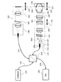
以下では、走査型網膜撮像システムについて、本発明によるコンセプトの実施形態によるHTの特性及びパフォーマンスの利点のいくつかに着目して論じることにする。最初に図1Aを参照しながら、従来の網膜OCT撮像システムのブロック図について説明する。図1Aに示されているように、システムには広帯域光源100が含まれており、これは光ファイバを含むことができる光源経路105と、参照分岐107と、サンプル分岐108とを介して供給され、これらはビームスプリッタ120によって互いに結合されている。ビームスプリッタ120を例えば、光ファイバカプラ又はバルクカプラ或いはマイクロ光学素子カプラとすることができる。ビームスプリッタ120は、約50/50〜90/10のスプリット比を生じさせることができる。さらに図1Aに示されているようにビームスプリッタ120は、光ファイバとして設けることのできる検出経路106を介して、サンプリングされた波長又は周波数の検出モジュールも結合されている。
In the following, the scanning retinal imaging system will be discussed with a focus on some of the characteristics and performance advantages of HT according to the concept embodiments according to the present invention. First, a block diagram of a conventional retinal OCT imaging system will be described with reference to FIG. 1A. As shown in FIG. 1A, the system includes a
サンプル分岐108は光ファイバを光学アセンブリと結合し、この光学アセンブリは、光ファイバから送出された光放射のビーム空間的プロフィルを成形する。一般的には光学アセンブリを、サンプル分岐撮像光学系140の入口に設けられたコリメータ141とすることができ、これはコリメートされた光を一対の走査ミラー142へ供給し、末端対物レンズ144を含む撮像レンズを通過させる。正常視の被検体の場合、末端対物レンズを介して光ファイバから供給される光ビームはコリメートされており、少なくとも公称的にはテレセントリックである。ここで用いた「正常視」とは、補正されていない正常な視覚を有する臨床状態のことであり、即ち補助として補正することなく、遠くの対象物に焦点を合わせる能力のある臨床状態のことである。また、「テレセントリック」とは、主光線が視野と交差して光軸と平行な光学系のことである。コリメートされた光は、被検体の角膜195及び水晶体193を通り、網膜196にフォーカシングされる。走査ミラーアセンブリ(複数の走査ミラー)142を被検体の瞳194に結像させることにより、走査されたビームは瞳を通って旋回し、最小のビネッティングで網膜面に結像する。OCTシステムの場合、結果として生じる画像は、参照分岐光学系110の設定による経路整合条件150と関連づけられたウィンドウ170内の被検体の深さ分解能画像である。
図1Aの網膜撮像システムの場合、眼はビームを網膜上にフォーカシングする。この場合、経路整合条件は、参照経路長と、眼の長さを含むサンプル分岐経路長とによって規定され、走査ビームの横方向分解能と被写界深度は、角膜におけるビームの直径により拘束される。典型的な参照分岐アセンブリ110には、入射コリメータ180と、可変の光学的減衰器181と、反射器アセンブリ182とが含まれる。反射器を、眼の長さのばらつきに合わせて調節するために、もっと一般的には、参照分岐経路長をサンプル分岐経路ポジション197と整合させるために、可動アセンブリ183と結合させることができる。被検体の屈折異常の補正は一般に、対物レンズ群144に対応づけられた1つ又は複数の可動レンズ素子143を介して扱われる。その際にしばしば望まれることは、散瞳(眼の拡張)を生じさせることなく、撮像できるようにすることであり、この場合、ビーム直径を約3mmよりも強制的に小さくする。
In the case of the retinal imaging system of FIG. 1A, the eye focuses the beam on the retina. In this case, the path matching condition is defined by the reference path length and the sample branch path length including the eye length, and the lateral resolution and depth of field of the scanning beam are constrained by the beam diameter in the cornea. . A typical
次に図1Bを参照しながら、他の一般的な網膜撮像システム、走査型レーザ眼検鏡(SLO)について説明する。図1Bに示されているように、SLOは図1AのOCTシステムとほぼ同様に構成されている。ただしSLOは、上述のOCTシステムに関して述べた干渉検出方式のシステムの代わりに、ダイレクト検出方式のシステム131を組み込んでいる。SLOシステムは参照分岐を備えていない。さらにSLOシステムは一般に、広帯域光源ではなく狭い線幅のレーザ光源を利用している。その他の点については、SLOシステムの光学撮像特性は、一般にOCTシステムと公称的には等価である。ただしSLOシステムによって取得されるのは、OCTシステムの場合のように深さ分解能画像ではなく、共焦点の被写界深度全体にわたって積分された底部画像である。
Next, another general retinal imaging system, a scanning laser ophthalmoscope (SLO) will be described with reference to FIG. 1B. As shown in FIG. 1B, the SLO is configured in much the same way as the OCT system of FIG. 1A. However, the SLO incorporates a
図1A及び図1Bに描かれたシステムの場合には双方ともに焦点制御が必要とされ、これは第一には、正視眼からの屈折偏差を補償するためであり、第二には、撮像における着目対象領域を制御するためのである。この種の走査ビーム型網膜撮像システムにおける焦点制御は一般に、末端対物レンズ144の相対ポジション制御143によって行われる。この焦点制御によって、走査ミラー142の共役及びビーム焦点に強く影響が及ぼされ、焦点と作動距離とOCTの場合には参照分岐経路長との調整が必要とされる。
In the case of the system depicted in FIGS. 1A and 1B, both require focus control, which is primarily to compensate for refractive deviation from the normal eye, and secondly in imaging. This is for controlling the target region of interest. Focus control in this type of scanning beam retinal imaging system is generally performed by
さらに、網膜の面に対し焦点をいっそう精密に制御することが望まれることも多い。この場合、網膜内層例えば神経線維層の強調、網膜外層例えば網膜色素上皮の強調、又は脈絡膜の強調が望まれる可能性があり、或いは、例えばぶどう膜炎に付随して生じる硝子体牽引又は炎症経過を観察する目的で、硝子体内部の構造の撮像が望まれる可能性もある。ここで用いた用語「ぶどう膜炎」とは、ぶどう膜又は眼の中央部分に炎症が引き起こされた臨床状態のことである。いくつかの実施形態によれば、ビネッティングを生じさせることなく、又は作動距離を変更することなく、焦点制御を調停することができる。 In addition, it is often desirable to control the focus more precisely with respect to the surface of the retina. In this case, enhancement of the inner retinal layer, such as the nerve fiber layer, enhancement of the outer retinal layer, such as the retinal pigment epithelium, or enhancement of the choroid may be desired, or the vitreous traction or inflammation process associated with, for example, uveitis There is a possibility that imaging of the internal structure of the vitreous body is desired for the purpose of observing. The term “uveitis” as used herein refers to a clinical condition in which inflammation has occurred in the uveum or central portion of the eye. According to some embodiments, the focus control can be arbitrated without causing vignetting or changing the working distance.
これらに加え有利となり得るのは、開口数を増加し、入射ビームサイズを大きくして横方向分解能を改善することである。現在のシステムの場合には、これは散瞳させることによってしか行えない。散瞳は臨床検査や外科的な検査で頻繁に利用されている。現在の眼の撮像システムでは、様々な環境に合わせてビーム直径を変更するフレキシビリティは提供されていない。 In addition to these, it may be advantageous to increase the numerical aperture and increase the incident beam size to improve lateral resolution. In the case of current systems, this can only be done with mydriasis. Mydriasis is frequently used in clinical and surgical tests. Current eye imaging systems do not provide the flexibility to change the beam diameter for various environments.
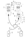
本発明によるコンセプトの実施形態は、従来のシステムにおけるこれらの欠点に取り組むものである。最初に図2Aを参照しながら、本発明によるコンセプトのいくつかの実施形態によるハイブリッド(HT)型テレスコープを含むシステムについて説明する。図2Aに示されているように、ここで説明する実施形態によれば、コリメータ141と走査ミラーアセンブリ142との間に、ハイブリッド型テレスコープ300が挿入されている。
Concept embodiments according to the present invention address these shortcomings in conventional systems. Referring initially to FIG. 2A, a system including a hybrid (HT) type telescope according to some embodiments of the concept according to the present invention will be described. As shown in FIG. 2A, according to the embodiment described herein, a
ここで説明するいくつかの実施形態においては、サンプル分岐中のビームスプリッタ120に続くシステム部分を、OCT撮像システムのサンプル分岐108における「ビーム成形光学アセンブリ」と称する場合もある。このため、いくつかの実施形態によるビーム成形光学アセンブリには、コリメータ141とハイブリッド型テレスコープが含まれる場合もある。以下で説明するようにビーム成形アセンブリを、光放射ビームとして光源から光放射を受光し、光放射ビームの空間プロフィルを成形するように構成することができる。
In some embodiments described herein, the portion of the system following the
もう一度図2Aを参照すると、ハイブリッド型テレスコープは、第1〜第3のレンズ310,320,330を有することができる。この図に描かれているように、第1の正のレンズ310に続いて第2の可動の負のレンズ320が、さらに第3の可動の正のレンズ330が設けられている。これらのレンズを、例えばピエゾトランスレータ又はステッピングモータによって駆動することができ、数μm或いは1mm又は数mmの精度で、数mm〜100mm以上までの範囲を有することができる。ハイブリッド型テレスコープ300のレンズを動かしてNA及び/又は焦点を調節できるようにするために、外部のハイブリッド型テレスコープコントローラ301を設けることができる。
Referring once again to FIG. 2A, the hybrid telescope can have first to
したがって本発明によるコンセプトのいくつかの実施形態によれば、ビーム成形光学アセンブリには、以下のようなレンズアセンブリが含まれている。即ちこのレンズアセンブリは制御入力に応答して、
・OCTシステムの焦点を変えることなくOCTシステムの開口数(NA)を変更するように構成可能である。又は、
・OCTシステムのNAを変えることなくOCTシステムの焦点を変更するように構成可能である。又は、
・OCTシステムのNAと焦点の双方を変更するように構成可能である。
Thus, according to some embodiments of the concept according to the present invention, the beam shaping optical assembly includes a lens assembly as follows. That is, the lens assembly is responsive to the control input,
It can be configured to change the numerical aperture (NA) of the OCT system without changing the focus of the OCT system. Or
It can be configured to change the focus of the OCT system without changing the NA of the OCT system. Or
It can be configured to change both the NA and focus of the OCT system.
コリメータ入射端に続いてハイブリッド型テレスコープを配置することによって、ハイブリッド型テレスコープを、決定論的なアパーチャとダイバージェンスを伴うレンズとして動作させることができ、これは光学系の残りの部分によって容易にモデリングすることができる。走査システムの手前でビームが調整されることから、対物レンズアセンブリにおける対物レンズのフォーカシングを不要とすることができ、被検体に対し相対的な一定の作動距離及び経路長で、焦点及びズームを制御することができる。さらに、眼の瞳のところでのミラーの共役に影響を及ぼすことなく、焦点を制御することができるので、被検体に関して最低限の調整で撮像条件を変更することができる。 By placing the hybrid telescope following the collimator entrance, the hybrid telescope can be operated as a lens with deterministic aperture and divergence, which is easily facilitated by the rest of the optics. Can be modeled. The beam is adjusted in front of the scanning system, eliminating the need for objective focusing in the objective lens assembly and controlling focus and zoom with a constant working distance and path length relative to the subject. can do. Furthermore, since the focus can be controlled without affecting the conjugate of the mirror at the pupil of the eye, the imaging conditions can be changed with a minimum adjustment for the subject.
この実施形態において必要であれば、対物レンズアセンブリの対物レンズ焦点コントローラ191(図2B参照)を用いてもよい。このようなコントローラは、被検体の瞳に対し相対的に走査ミラーの共役を制御するために有利である場合もあり、これを利用することは一般に見過ごされているけれども、角膜の屈折力又は前房の長さが設計条件とは異なる場合に役立つ可能性がある。 If necessary in this embodiment, the objective lens focus controller 191 (see FIG. 2B) of the objective lens assembly may be used. Such a controller may be advantageous for controlling the conjugate of the scanning mirror relative to the pupil of the subject, and the use of this is generally overlooked, but the refractive power of the cornea or the front This may be useful when the tuft length is different from the design conditions.
本発明によるコンセプトのいくつかの実施形態によれば、約2mm〜約6mmの角膜におけるビーム直径に適応させるために、ハイブリッド型テレスコープ300を用いることで、+30D〜−30Dの焦能力の範囲に関して3Xのズームで、眼の撮像システム140を調節することができる。このような範囲であれば、ヒト個体群における屈折異常の範囲が100%、効果的にカバーされる一方、網膜前方の硝子体内の構造を撮像するのに十分な能力をもたせることができる。なお、ここで用いた用語「硝子体」とは、網膜と水晶体との間の領域を占める透明なゼラチン状の物質のことである。さらにこの撮像システムを、+60Dの屈折補正に適合させるために調節することができ、これは無水晶体眼のケースや、齧歯類など人類以外の何らかの動物モデルのために必要となる場合がある。
In accordance with some embodiments of the concept according to the present invention, using a
上述の無水晶体眼の場合には眼のレンズが存在しない状態となり、被検体において時折遭遇するものである。眼のレンズは、約+30ジオプトリ(D)、眼の屈折力に寄与する。無水晶体眼の患者の撮像のためには一般に、光学系が眼のレンズのパワーを代替する必要がある。したがって図2Bに示されているように、被検体の眼には(図2Aに示されている)本来のレンズもしくは代替のレンズ194が欠けており、このため網膜の撮像をうまく行うためには、付加的なレベルの焦能力が必要とされる。本発明によるコンセプトのいくつかの実施形態によれば、無水晶体眼を含め人類及び人類以外の屈折範囲拡大に適合させるために、ハイブリッド型テレスコープ300によって、+60D〜−30Dの範囲の焦能力が提供される。本発明によるコンセプトのさらに別の実施形態によれば、無水晶体眼を含め人類の屈折範囲に適合させるために、ハイブリッド型テレスコープ300によって、+40D〜−20Dの焦能力の範囲が提供される一方、末端対物レンズ144によって、+20D〜−10Dの補助的な焦点範囲が、対物レンズ群の各要素間の相対運動191を介して提供される。
In the case of the above-mentioned aphakic eye, there is no eye lens, which is sometimes encountered in the subject. The ophthalmic lens contributes about +30 diopters (D), the refractive power of the eye. In general, for imaging of aphakic patients, an optical system needs to replace the power of the eye lens. Thus, as shown in FIG. 2B, the subject's eye lacks the original lens or alternative lens 194 (shown in FIG. 2A), so that to successfully image the retina An additional level of burning ability is required. According to some embodiments of the concept according to the present invention, the
図2A及び図2Bを参照しながら、本発明によるコンセプトのいくつかの実施形態についてのみ説明したが、特定の用途のためにハイブリッド型テレスコープと対物レンズの屈折能力とズーム能力との間で適切なバランスを提供することも考えられる。いくつかの種は生来、正常視ではなく、光学系には屈折のバイアスが含まれている可能性もある。例えばある齧歯動物は、網膜結像のために公称60D〜90Dの焦能力を必要とされる可能性があり、ウサギは6Dを必要とする可能性がある。このため光学系に、被検体の公称屈折に対するバイアスを含めることができ、その際、ハイブリッド型テレスコープを用いることによって、種に関連する制御範囲が提供される。 While only some embodiments of the concept according to the present invention have been described with reference to FIGS. 2A and 2B, it is appropriate between the refractive and zoom capabilities of a hybrid telescope and objective lens for a particular application. Providing a good balance. Some species are inherently not normal vision, and the optical system may contain a refractive bias. For example, certain rodents may require a nominal 60D-90D focusing ability for retinal imaging, and rabbits may require 6D. For this reason, the optical system can include a bias for the nominal refraction of the subject, with the use of a hybrid telescope to provide a control range related to the species.
次に図3を参照しながら、シンプルな角膜撮像システムについて説明する。同じ要素には、一貫して同じ参照符号が付されている。したがって簡略にするため、図1A及び図1Bを参照しながら既に説明した図3中の要素に関する詳細についてはここでは繰り返さない。角膜撮像システムは、一般に固定焦点及び固定開口数のシステムであり、これは一定の分解能、倍率、視野及び被写界深度を有する。被写界深度の変更のためには、それぞれ異なるレンズを適合させることができる。ここでは角膜に関して示されているけれども、この種のシステムを、収斂した瞳孔を通して撮像が行われる他の多くの用途において利用することができ、したがって走査面を共役の瞳に結像させる必要がない。前眼部の撮像とは異なる用途として挙げられるのは、例えば皮膚の撮像である。 Next, a simple corneal imaging system will be described with reference to FIG. The same elements are denoted by the same reference numerals throughout. Therefore, for the sake of brevity, the details regarding the elements in FIG. 3 already described with reference to FIGS. 1A and 1B will not be repeated here. A corneal imaging system is generally a fixed focus and fixed numerical aperture system that has a constant resolution, magnification, field of view and depth of field. Different lenses can be adapted to change the depth of field. Although shown here with respect to the cornea, this type of system can be utilized in many other applications where imaging is done through a convergent pupil, thus eliminating the need to image the scan plane to a conjugate pupil. . An application different from imaging of the anterior segment is, for example, imaging of the skin.
次に図4を参照しながら、前眼部撮像のために焦点制御及び開口数制御を利用する本発明によるコンセプトのいくつかの実施形態による撮像システムのブロック図について説明する。この図においても同じ要素には、一貫して同じ参照符号が付されている。したがって簡略するため、既に説明した図4中の要素に関する詳細についてはここでは繰り返さない。図4に示されているように、コリメータ141と走査ミラーアセンブリ142との間に、本発明によるコンセプトの実施形態によるハイブリッド型テレスコープ300が配置されている。この場合、第1の正のレンズ310に続いて第2の可動の負のレンズ320が、さらに第3の可動の正のレンズ330が設けられている。これらのレンズを、例えばピエゾトランスレータ又はステッピングモータによって駆動することができ、mmの何分の1又は1mmの精度で、数mm〜10又はそれ以上のmmの範囲を有することができる。コリメータ入射端141に続いて配置されたハイブリッド型テレスコープ300は、決定論的なアパーチャとダイバージェンスを伴うレンズとして動作し、これは光学系の残りの部分によって容易にモデリングすることができる。
Referring now to FIG. 4, a block diagram of an imaging system according to some embodiments of the concept of the present invention that utilizes focus control and numerical aperture control for anterior segment imaging will be described. In this figure, the same elements are denoted by the same reference numerals throughout. Therefore, for the sake of brevity, the details relating to the elements in FIG. 4 already described will not be repeated here. As shown in FIG. 4, a
次に図5を参照しながら、これまで述べてきた実施形態による撮像システムのさらに別の実施形態について説明する。同じ要素には、一貫して同じ参照符号が付されている。したがって簡略するため、既に説明した図5中の要素に関する詳細についてはここでは繰り返さない。図5に示されているように、例えばケプラー式テレスコープとすることができるビームエキスパンダ530が、ハイブリッド型テレスコープ300と、図5に描かれている実施形態によれば、さらに走査ミラー142と、の次に続いている。図5に示したジオメトリによれば、システムの出射瞳において望ましいビーム寸法を達成するのに必要とされるミラーサイズが低減される、という利点を得ることができる。例えばここで論じている眼の撮像の具体例によれば、6mmよりも小さいミラー寸法を維持することが望まれることが多く、さらに3mm以下が望まれることも多い。このような環境では、3X〜5Xのズームリレーが有利となる可能性がある。
Next, still another embodiment of the imaging system according to the embodiment described so far will be described with reference to FIG. The same elements are denoted by the same reference numerals throughout. Therefore, for the sake of brevity, the details relating to the elements in FIG. 5 already described will not be repeated here. As shown in FIG. 5, a
もっと一般的に言えば、医療用撮像におけるラパロスコープ及び産業用撮像のためのホロスコープを含め、多くの用途のために内視鏡を提供することが望まれる場合もある。内視鏡の入射端でハイブリッド型テレスコープ300を利用し、それに続いて、小型スキャナ例えば1.0mm程度の小さいミラーを有するマイクロエレクトロメカニカルシステム(MEMS)スキャナを備えた走査システムを配置し、さらに続いて、望ましい倍率を有する1つ又は複数のリレーテレスコープを配置することによって、ダイレクト検出方式及び干渉検出方式の双方の実現形態のために、可変の焦点距離と被写界深度を有する極めて有用な内視鏡を提供することができる。
More generally, it may be desirable to provide an endoscope for many applications, including a laparoscope in medical imaging and a horoscope for industrial imaging. Using a
次に図6を参照しながら、本発明によるコンセプトの実施形態によるハイブリッド型テレスコープ300を含む、撮像を行わない用途について説明する。図6には、レーザデリバリの適用事例が示されている。治療用のレーザデリバリの適用事例のために強く望まれるのは、ビームの最大強度ポジション(焦点)とビーム強度(ビームウェスト)を制御することである。レーザデリバリシステム内に配置された本発明によるコンセプトの実施形態によるハイブリッド型テレスコープ300によれば、最大強度とビームウェストの双方を制御することができる。したがって、走査型ジオメトリを利用して、又は非走査型ジオメトリを利用して、及びリレー又はビームエキスパンダをそれに続いて設けて、又は設けずに、本発明によるコンセプトの実施形態を利用することができる。
Next, with reference to FIG. 6, a non-imaging application including a
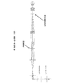
次に図7A〜7Fを参照しながら、本発明によるコンセプトの実施形態によるハイブリッド型テレスコープについて説明する。ここでは特に、3Xリレービームエキスパンダと+30D〜−30Dの全焦点範囲と3Xの倍率範囲とを有するハイブリッド型テレスコープを利用した、網膜撮像システムの1つの特別な実現形態について、図7A〜図7Fを参照しながら説明する。ここで開示する実施形態による網膜撮像システムについて手短に述べておくと、小さい開口数(NA)では、焦点のビーム直径は13.5μmであり、高い開口数では、ビーム直径は4.5μmまで低減される。図面には、ハイブリッド型テレスコープレンズのパワー及び間隔t1,t2が、システムのパフォーマンス範囲における6つの動作条件各々について示されている。図面に示されているように、ハイブリッド型テレスコープの正のレンズ群は、同じ40mmの実効焦点距離(EFL)を有しており、これは+20ジオプトリに等しい。中央の負のレンズは、−10mmの実効焦点距離を有しており、これは−100ジオプトリに等しい。最大ビーム直径(最大開口数、最小fナンバー)におけるレンズ間隔は、図7Aの第1のレンズ群と第2のレンズ群との間ではt1=18.90mm、第2のレンズ群と第3のレンズ群との間ではt2=21.20mmである。レンズのパワーと間隔を、同等の結果を達成するためにコンフィギュレーションすることができるけれども、特定のレンズの組み合わせが唯一の解決手段ではなく、本発明によるコンセプトの実施形態はそれらに限定されるものではない。 Next, a hybrid telescope according to an embodiment of the concept of the present invention will be described with reference to FIGS. Here, in particular, one particular implementation of a retinal imaging system utilizing a 3X relay beam expander, a hybrid telescope having a full focal range of + 30D to -30D and a magnification range of 3X is shown in FIGS. This will be described with reference to 7F. Briefly describing the retinal imaging system according to embodiments disclosed herein, for small numerical apertures (NA), the focal beam diameter is 13.5 μm and for high numerical apertures the beam diameter is reduced to 4.5 μm Is done. The drawing shows the power and spacing t 1 , t 2 of the hybrid telescope lens for each of the six operating conditions in the system performance range. As shown in the drawing, the positive lens group of the hybrid telescope has the same effective focal length (EFL) of 40 mm, which is equal to +20 diopters. The central negative lens has an effective focal length of -10 mm, which is equal to -100 diopters. The lens spacing at the maximum beam diameter (maximum numerical aperture, minimum f-number) is t 1 = 1.90 mm between the first lens group and the second lens group in FIG. 7A, and the second lens group and the third lens group. T 2 = 21.20 mm between the two lens groups. Although lens power and spacing can be configured to achieve equivalent results, specific lens combinations are not the only solution, and embodiments of the concept according to the invention are limited to them is not.
図7Bに示されているように、最小ビームサイズのために、レンズの間隔をt1=24.70mm、t2=2.00mmに変更することによって、システムのNAを小さくすることができる。図7Cに示されているように、近視眼の−30Dに適合させるために、最大の開口数とビーム直径でレンズ間隔をt1=38.70mm、t2=24.60mmに変更することにより、焦点が調節される。図7Dに示されているように、最小の開口数とビーム直径のために、同じシステムがt1=31.95、t2=43.05に調節される。図7Eの場合、遠視眼の+30Dに適合させるために、最大の開口数とビーム直径でレンズ間隔をt1=22.10mm、t2=46.90mmに変更することによって、焦点が調節される。最後に図7Fの場合、最小の開口数とビーム直径のために、同じシステムがt1=24.92、t2=19.28に調節される。 As shown in FIG. 7B, the system NA can be reduced by changing the lens spacing to t 1 = 24.70 mm, t 2 = 2.00 mm for minimum beam size. As shown in FIG. 7C, to adapt to -30D for myopic eyes, by changing the lens spacing at maximum numerical aperture and beam diameter to t 1 = 38.70 mm, t 2 = 24.60 mm, The focus is adjusted. As shown in FIG. 7D, the same system is adjusted to t 1 = 31.95, t 2 = 43.05 for minimum numerical aperture and beam diameter. In the case of FIG. 7E, the focus is adjusted by changing the lens spacing to t 1 = 22.10 mm, t 2 = 46.90 mm at the maximum numerical aperture and beam diameter to accommodate + 30D of the hyperopic eye. . Finally, in FIG. 7F, the same system is adjusted to t 1 = 24.92, t 2 = 19.28 for minimum numerical aperture and beam diameter.
次に図7Gを参照するとこの図には、近視眼から無水晶体眼による遠視眼に至るまで全範囲に適合させるために、3Xリレービームエキスパンダと+60D〜−30Dまでの拡張された焦点範囲とを有するハイブリッド型テレスコープを用いた、網膜撮像システムの具体例が示されている。ここで用いた「無水晶体眼の遠視眼」とは、本来の又は代替の水晶体が欠けている患者が強度の遠視である臨床状態のことである。図7Gに示されているように、低倍率の実施形態のために、ハイブリッド型テレスコープのレンズのパワーと間隔t1=27.18mm及びt2=43.32mmが規定されている。 Referring now to FIG. 7G, this figure shows a 3X relay beam expander and an extended focus range from + 60D to -30D to accommodate the entire range from myopic eyes to hyperopic eyes with aphakic eyes. A specific example of a retinal imaging system using a hybrid telescope is shown. As used herein, "aphatic hyperopic eye" refers to a clinical condition in which a patient lacking the original or alternative crystalline lens has severe hyperopia. As shown in FIG. 7G, the lens power and spacing t 1 = 27.18 mm and t 2 = 43.32 mm of the hybrid telescope are specified for the low magnification embodiment.
図8A及び図8Bを参照すると、これらの図には具体例として、高分解能の角膜撮像に適した走査型顕微鏡撮像システムの実施形態が描かれている。図8A及び図8Bに描かれている実施形態の場合、システムは、1.4〜4の有効fナンバー範囲と、約3Xのズーム範囲とを有しており、これによって、大きい開口数(NA)範囲終端で、角膜のための共焦点顕微鏡による細胞の撮像に適した撮像特性が得られ、小さい開口数(NA)範囲終端で、厚み全体の角膜画像に適した撮像特性が得られる。 Referring to FIGS. 8A and 8B, these figures depict, as a specific example, an embodiment of a scanning microscope imaging system suitable for high-resolution corneal imaging. For the embodiment depicted in FIGS. 8A and 8B, the system has an effective f-number range of 1.4 to 4 and a zoom range of about 3 ×, which results in a large numerical aperture (NA). ) At the end of the range, an imaging characteristic suitable for cell imaging with a confocal microscope for the cornea is obtained, and at the end of the small numerical aperture (NA) range, an imaging characteristic suitable for a corneal image of the entire thickness is obtained.
図8A〜図8Bに示されているように、角膜撮像システムは、3.2mmの作動距離、約3xのズーム(開口数又はビーム直径の範囲)及び1.2mmの視野で、無限大に補正された顕微鏡対物レンズを有している。f/1.4においてビームは、1.4μmの回折限界直径と、14μmの被写界深度を有している。f/4においてビームは、4.2μmの回折限界直径と、124μmの被写界深度を有している。これらの撮像モードが切り替え可能であることによって、単一の機器が細胞レベルの撮像のためにも断層撮影撮像のためにも用いられる、という臨床的に重要な利点が得られる。マルチレンジスキャニングによる光学的な像とともに、視野全体の視覚的及びビデオによる像も同時に得るために、このようなコンフィギュレーションをステレオズーム顕微鏡の無限空間に組み込むことができる。これまで、いくつかのコンフィギュレーションについて具体例として説明してきたが、自明である通り、本発明によるコンセプトの実施形態がこれらの実施形態に限定されるものではない。当業者であれば、特定の設計目標に整合させるために、代案となるコンフィギュレーションも考えられる。 As shown in FIGS. 8A-8B, the corneal imaging system corrects to infinity with a working distance of 3.2 mm, a zoom of about 3 × (numerical aperture or beam diameter range) and a 1.2 mm field of view. A microscope objective lens. At f / 1.4, the beam has a diffraction limited diameter of 1.4 μm and a depth of field of 14 μm. At f / 4, the beam has a diffraction limited diameter of 4.2 μm and a depth of field of 124 μm. The ability to switch between these imaging modes provides a clinically significant advantage that a single device can be used for both cellular level imaging and tomographic imaging. Such a configuration can be incorporated into the infinite space of a stereo zoom microscope to simultaneously obtain visual and video images of the entire field of view as well as optical images from multi-range scanning. So far, several configurations have been described as specific examples. However, as is obvious, embodiments of the concept according to the present invention are not limited to these embodiments. Those skilled in the art will envision alternative configurations to align with specific design goals.
次に図9A〜図9Cを参照しながら、本発明によるコンセプトの実施形態によるハイブリッド型テレスコープを使用した内視鏡撮像システムの実施形態を具体例として示した図について説明する。これらの図面に示されているように、この内視鏡のコンフィギュレーションによれば、ハイブリッド型テレスコープ300に続いてテレセントリックミラーリレー(テレセントリックフォーカスレンズ)990とホプキンス型内視鏡リレー993が、さらにこれに続いて末端のテレセントリック対物レンズ995が設けられており、これによって、可変のNAと焦点距離とを有する30cm長の走査ビームのリジッドな内視鏡が得られる。
Next, with reference to FIG. 9A to FIG. 9C, a diagram illustrating a specific example of an embodiment of an endoscope imaging system using a hybrid telescope according to an embodiment of the concept of the present invention will be described. As shown in these drawings, according to the configuration of the endoscope, a telecentric mirror relay (telecentric focus lens) 990 and a Hopkins
図9Aに示されているように、ハイブリッド型テレスコープ300(t1=15.00mm、t2=23.33mm)は、f/4.6の動作のために、3mmの作動距離(実効焦点距離)、178μmの被写界深度(DOF)、5μmのビーム分解能、6mmの視野(FOV)によってコンフィギュレーションされている。図9Bの場合、ハイブリッド型テレスコープのセッティング(t1=14.5mm、t2=14.30mm)が、8mmというさらに長い作動距離のために変更されており、これによって175μmの被写界深度、5μmのビーム分解能、及び6mmの視野で、f/4.7の動作が維持される。図9C(t1=25.00mm、t2=10.00mm)の場合、3mmという狭い作動離が確保されており、15μmのビーム分解能と1.58mmの被写界深度のために、NAがf/14に低減されている。個々の図面には、ハイブリッド型テレスコープのレンズのパワー及び間隔t1及びt2も示されている。 As shown in FIG. 9A, the hybrid telescope 300 (t 1 = 15.00 mm, t 2 = 23.33 mm) has a working distance (effective focus) of 3 mm for f / 4.6 operation. Distance), configured with 178 μm depth of field (DOF), 5 μm beam resolution, 6 mm field of view (FOV). In the case of FIG. 9B, the setting of the hybrid telescope (t 1 = 14.5 mm, t 2 = 14.30 mm) has been changed for a longer working distance of 8 mm, which results in a depth of field of 175 μm. With a beam resolution of 5 μm and a field of view of 6 mm, f / 4.7 operation is maintained. In the case of FIG. 9C (t 1 = 25.00 mm, t 2 = 10.00 mm), a narrow working separation of 3 mm is ensured, and because of the 15 μm beam resolution and 1.58 mm depth of field, the NA is It is reduced to f / 14. The individual drawings also show the power and spacing t 1 and t 2 of the hybrid telescope lens.
次に図10を参照しながら具体例として、本発明によるコンセプトのいくつかの実施形態による走査ビーム型テレスコープの可変の焦点及びズームを使用した方法について説明する。ブロック1000においてオペレーションがスタートし、着目対象領域に入ると、システムの初期撮像範囲を最大にする目的で、内視鏡のハイブリッド型テレスコープが、長焦点距離と小さいNAにセットされる。
Now referring to FIG. 10, as an example, a method using variable focus and zoom of a scanning beam telescope according to some embodiments of the concept according to the present invention will be described. When operation starts at
着目対象構造が同定されると、NAが増加され、これによって被写界深度が減少するけれども、焦点面に沿って輝度が増加する(ブロック1010)。NAが大きい場合、生検鉗子のような器具とともに内視鏡を利用できるようにするために、焦点距離が例えば鉗子等の作動距離とマッチするように、焦点距離が変更される(ブロック1020)。着目対象ターゲット領域周囲の構造を観察するために、開口数及び焦点距離を要求通りに変更することができる(ブロック1030)。これまで述べてきたように、本発明によるコンセプトのいくつかの実施形態は、OCTシステムに関連して利用される。OCTシステムの場合、ハイブリッド型テレスコープの焦点距離又はNAが変更されると、着目対象領域を干渉窓内に維持するために、参照分岐が調整される。この内視鏡システムを、非干渉走査ビーム型撮像システムにも、レーザデリバリシステムにも、同じように利用することができる。 Once the structure of interest is identified, the NA is increased, thereby decreasing the depth of field but increasing the brightness along the focal plane (block 1010). If the NA is large, the focal length is changed so that the focal length matches the working distance of, for example, a forceps, so that the endoscope can be used with an instrument such as a biopsy forceps (block 1020). . To observe the structure around the target area of interest, the numerical aperture and focal length can be changed as desired (block 1030). As described above, some embodiments of the concept according to the present invention are utilized in connection with an OCT system. In the case of the OCT system, when the focal length or NA of the hybrid telescope is changed, the reference branch is adjusted in order to maintain the target region of interest within the interference window. This endoscope system can be used in the same way for both a non-interfering scanning beam imaging system and a laser delivery system.
以上、システム及び装置のブロック図及び/又はフローチャートを参照しながら、具体例としての実施形態について説明してきた。ブロック内に記した機能/動作が、フローチャートに記載されている順序とは異なる順序で現れるようにしてもよい。例えば、相前後して示されている2つのブロックを、必要とされる機能/動作に応じて、実際には実質的に同時に実行してもよいし、あるいはそれらのブロックを時には逆の順序で実行してもよい。さらに、フローチャート及び/又はブロック図における所定のブロックの機能を、複数のブロックに分けてもよく、及び/又は、フローチャート及び/又はブロック図の2つ以上のブロックの機能を、少なくとも部分的に統合してもよい。 The exemplary embodiments have been described above with reference to block diagrams and / or flowcharts of systems and devices. The functions / operations described in the blocks may appear in an order different from the order described in the flowchart. For example, two blocks shown one after the other may actually be executed substantially simultaneously, depending on the function / operation required, or they may sometimes be executed in reverse order. May be executed. Furthermore, the function of a given block in the flowchart and / or block diagram may be divided into multiple blocks and / or the functions of two or more blocks in the flowchart and / or block diagram are at least partially integrated. May be.
これまで図面及び明細書では、本発明によるコンセプトの実施形態の具体例を開示してきた。ただし、本発明によるコンセプトの基本原理から実質的に逸脱することなく、これらの実施形態に多くの変更及び修正を加えることができる。したがって特定の用語を用いてきたけれども、それらは汎用的かつ説明の都合上使われたにすぎず、限定を意図したものではなく、本発明によるコンセプトの範囲は、以下の特許請求の範囲によって規定されるものである。 So far, the drawings and specification have disclosed specific examples of embodiments of the concept according to the present invention. However, many variations and modifications can be made to these embodiments without substantially departing from the basic principles of the concept according to the present invention. Thus, although specific terms have been used, they have been used for general and explanatory purposes only, and are not intended to be limiting, the scope of the concept according to the invention is defined by the following claims. It is what is done.
Claims (2)
サンプル内の着目対象領域に入ったことに応じて、ハイブリッド型テレスコープ(HT)を、長い焦点距離と小さい開口数(NA)にセットするステップと、
前記サンプルの着目対象領域内の着目対象構造を同定するステップと、
前記開口数を大きくして、被写界深度を低減し、かつ、焦点面の輝度を高めるステップと、
前記焦点距離が前記走査ビーム型システムに対応づけられた器具の作動距離と整合するよう、焦点距離を変化させるステップと、
を含む方法。 In a method of operating a scanning beam type system,
Setting a hybrid telescope (HT) to a long focal length and a small numerical aperture (NA) in response to entering a region of interest in the sample;
Identifying a target structure in a target region of the sample;
Increasing the numerical aperture to reduce the depth of field and increasing the brightness of the focal plane;
Changing the focal length so that the focal length matches the working distance of an instrument associated with the scanning beam type system;
Including methods.
初期ビーム直径および所定のビーム広がりをもつ光ビームを伝送するように構成された光放射入射源と、
ビームコンディショニングアセンブリと、
を具え、
前記ビームコンディションニングアセンブリは、前記入射源からの光放射を受光するように構成された入射端と、前記ビーム直径および前記ビーム広がりを変化させる手段と、出射端と、を有し、前記出射端は、ビーム伝播方向に対し直交する少なくとも1つの方向に沿って光放射ビームを操作する手段へ、前記光放射を配向し、
前記光走査ビーム型システムは、
前記操作された光放射ビームを、被検体に対応づけられた着目対象領域へ配向する手段と、
前記着目対象領域から散乱した、または前記着目対象領域を通して伝送された光放射の少なくとも一部分を収集する手段と、
収集された前記光放射を検出する手段と、
前記光放射ビームと前記被検体との相互作用に応答して、検出された光放射を処理し、前記着目対象領域の特性から導出された画像を生成する手段と、
前記ビームコンディショニングアセンブリと連携するコントローラと、
を具え、
前記コントローラは、前記ビームコンディションニングアセンブリの少なくとも2つの運動自由度を制御するように構成されており、
前記コントローラは、前記光走査ビーム型システムを、固定されたシステム開口数で予め規定された複数の焦点ポジションのうちの1つにセットするように構成されており、かつ、前記コントローラは前記光走査ビーム型システムを、固定された焦点ポジションで予め規定された複数の開口数のうちの1つにセットするように構成されている、
光走査ビーム型システム。 In the optical scanning beam type system, the optical scanning beam type system includes:
A light emitting incident source configured to transmit a light beam having an initial beam diameter and a predetermined beam spread;
A beam conditioning assembly;
With
The beam conditioning assembly has an incident end configured to receive light radiation from the incident source, means for changing the beam diameter and the beam divergence, and an output end, the output end Directs the light radiation to means for manipulating the light radiation beam along at least one direction orthogonal to the beam propagation direction;
The optical scanning beam type system includes:
Means for directing the manipulated light radiation beam to a region of interest associated with a subject;
Means for collecting at least a portion of light radiation scattered from or transmitted through the region of interest;
Means for detecting the collected light radiation;
Means for processing the detected light radiation in response to the interaction of the light radiation beam and the subject to generate an image derived from the characteristics of the region of interest;
A controller associated with the beam conditioning assembly;
With
The controller is configured to control at least two degrees of freedom of motion of the beam conditioning assembly;
The controller is configured to set the optical scanning beam type system to one of a plurality of pre-defined focal positions with a fixed system numerical aperture, and the controller is configured to scan the optical scanning system. Configured to set the beam type system to one of a plurality of predefined numerical apertures at a fixed focal position;
Optical scanning beam type system.
Applications Claiming Priority (3)
| Application Number | Priority Date | Filing Date | Title |
|---|---|---|---|
| US201361830820P | 2013-06-04 | 2013-06-04 | |
| US61/830,820 | 2013-06-04 | ||
| PCT/US2014/040836 WO2014197553A2 (en) | 2013-06-04 | 2014-06-04 | Hybrid telescope for optical beam delivery and related systems and methods |
Publications (2)
| Publication Number | Publication Date |
|---|---|
| JP2016523613A JP2016523613A (en) | 2016-08-12 |
| JP6373366B2 true JP6373366B2 (en) | 2018-08-15 |
Family
ID=51904220
Family Applications (1)
| Application Number | Title | Priority Date | Filing Date |
|---|---|---|---|
| JP2016518427A Active JP6373366B2 (en) | 2013-06-04 | 2014-06-04 | Method of operating scanning beam type system and optical scanning beam type system |
Country Status (5)
| Country | Link |
|---|---|
| US (2) | US9949634B2 (en) |
| EP (1) | EP3003123B1 (en) |
| JP (1) | JP6373366B2 (en) |
| CN (1) | CN105473055B (en) |
| WO (1) | WO2014197553A2 (en) |
Families Citing this family (20)
| Publication number | Priority date | Publication date | Assignee | Title |
|---|---|---|---|---|
| MX2016012066A (en) * | 2014-03-18 | 2017-01-19 | Integrated Medical Systems Int Inc | Optically adaptive endoscope. |
| CN104783755A (en) * | 2015-04-29 | 2015-07-22 | 中国科学院光电技术研究所 | Self-adaptive optical retina imaging device and method |
| JP6518132B2 (en) * | 2015-05-26 | 2019-05-22 | 株式会社トプコン | Ophthalmic imaging device |
| CN108780222B (en) * | 2015-12-08 | 2021-07-06 | 密歇根大学董事会 | 3D MEMS scanner for real-time cross-section endomicroscopy |
| CN106371374A (en) * | 2016-11-07 | 2017-02-01 | 福州幻科机电科技有限公司 | Intelligent control circuit system for minimally invasive endoscopic four-freedom-degree locator |
| CA3045606A1 (en) * | 2017-01-19 | 2018-07-26 | Novartis Ag | Method and apparatus for optical coherence tomography scanning |
| DE102017203010A1 (en) * | 2017-02-24 | 2018-08-30 | Carl Zeiss Meditec Ag | Method and device for the high-resolution topography of the cornea of an eye |
| NL2018857B1 (en) * | 2017-05-05 | 2018-11-09 | Illumina Inc | Systems and methods for improved focus tracking using a light source configuration |
| JP7031205B2 (en) * | 2017-09-29 | 2022-03-08 | 株式会社ニデック | OCT device |
| JP7050282B2 (en) | 2017-12-22 | 2022-04-08 | 株式会社トーメーコーポレーション | Optical tomography equipment and light source equipment used for it |
| US20200375440A1 (en) * | 2017-12-28 | 2020-12-03 | Beijing Fanxing Guangdiang Medical Treatment Equipment Co., Ltd. | Endoscope system and integrated design method for endoscope camera optical system |
| EP3530175A1 (en) * | 2018-02-26 | 2019-08-28 | Nokia Technologies Oy | Apparatus for optical coherence tomography |
| JP7103813B2 (en) * | 2018-03-27 | 2022-07-20 | 株式会社トプコン | Ophthalmic equipment |
| WO2019193529A1 (en) | 2018-04-06 | 2019-10-10 | Amo Wavefront Sciences, Llc | Methods and systems for corneal topography with in-focus scleral imaging |
| CN108283484B (en) * | 2018-04-08 | 2024-01-16 | 视微影像(河南)科技有限公司 | OCT fundus imaging vision compensating optical system |
| EP3608625B1 (en) * | 2018-08-07 | 2023-10-25 | Hexagon Technology Center GmbH | Oct measuring system |
| CN109238131B (en) * | 2018-08-09 | 2020-12-22 | 江苏度微光学科技有限公司 | Transverse ultrahigh-resolution optical coherence tomography method and system |
| KR102143484B1 (en) * | 2018-11-12 | 2020-08-12 | 한국기초과학지원연구원 | Dual mode microscope stystem |
| DE102019113975B4 (en) * | 2019-05-24 | 2023-10-19 | Abberior Instruments Gmbh | Method and device for monitoring the focus state of a microscope and microscope |
| CN114486176A (en) * | 2022-01-24 | 2022-05-13 | 执鼎医疗科技(杭州)有限公司 | Confocal distance imaging calibration device and calibration method |
Family Cites Families (99)
| Publication number | Priority date | Publication date | Assignee | Title |
|---|---|---|---|---|
| US4167302A (en) | 1976-08-25 | 1979-09-11 | Tokyo Kogaku Kikai Kabushiki Kaisha | Surgical microscopes with L-shaped mounting brackets |
| US4431258A (en) | 1981-12-15 | 1984-02-14 | Gte Laboratories Incorporated | Optical fiber transmission system and dichroic beam splitter therefor |
| JPS5897730U (en) | 1981-12-24 | 1983-07-02 | ヤマハ株式会社 | Automatic focus device in optical information recording/reproducing device |
| US4544243A (en) | 1984-05-24 | 1985-10-01 | Cooper Lasersonics, Inc. | Heads up display for microscope using remotely controlled instrument |
| IL77354A (en) | 1985-12-16 | 1989-10-31 | Sofin Ltd | Combiner for optical or electro-optical systems |
| US5055663A (en) | 1988-06-28 | 1991-10-08 | Asahi Kogaku Kogyo Kabushiki Kaisha | Optical scanning system and method for adjusting thereof |
| NL8803012A (en) | 1988-12-08 | 1990-07-02 | Philips Nv | Optical scanning device provided with a focusing control system and an integrated circuit for use in the focusing control system. |
| US6099522A (en) | 1989-02-06 | 2000-08-08 | Visx Inc. | Automated laser workstation for high precision surgical and industrial interventions |
| US5061018A (en) | 1990-04-02 | 1991-10-29 | Time Surgical, Inc. | Microscope accessory equipment container |
| US5168386A (en) | 1990-10-22 | 1992-12-01 | Tencor Instruments | Flat field telecentric scanner |
| JPH05173087A (en) | 1991-06-26 | 1993-07-13 | Asahi Optical Co Ltd | Automatic focus scanning type optical device |
| US5493109A (en) | 1994-08-18 | 1996-02-20 | Carl Zeiss, Inc. | Optical coherence tomography assisted ophthalmologic surgical microscope |
| EP1231496B1 (en) | 1994-08-18 | 2004-12-29 | Carl Zeiss AG | Optical coherence tomography assisted surgical apparatus |
| US5491524A (en) | 1994-10-05 | 1996-02-13 | Carl Zeiss, Inc. | Optical coherence tomography corneal mapping apparatus |
| US5907431A (en) | 1995-03-14 | 1999-05-25 | Leica Mikroskopie Systems Ag | Microscope including automatic ocular adaptation |
| EP0871913B1 (en) | 1995-05-17 | 2002-08-07 | Leica Mikroskopie Systeme AG | Microscope |
| JP4175580B2 (en) | 1996-05-31 | 2008-11-05 | ディスコヴィジョン アソシエイツ | System for adjusting spot size of optical recording system |
| US5795295A (en) | 1996-06-25 | 1998-08-18 | Carl Zeiss, Inc. | OCT-assisted surgical microscope with multi-coordinate manipulator |
| JP3925576B2 (en) | 1997-07-24 | 2007-06-06 | 株式会社ニコン | Projection optical system, exposure apparatus including the optical system, and device manufacturing method using the apparatus |
| US7246905B2 (en) | 1998-11-13 | 2007-07-24 | Jean Benedikt | Method and an apparatus for the simultaneous determination of surface topometry and biometry of the eye |
| DE19930408A1 (en) | 1999-07-02 | 2001-01-04 | Zeiss Carl Fa | An optical coherence computer tomography (OCT) system for surgical support combines pre-operation tissue position data and CT data for use in navigation assistance for the operating surgeon |
| US6451010B1 (en) | 2000-04-14 | 2002-09-17 | Lumenis Inc. | Zoom handpiece for laser surgery |
| US6685317B2 (en) | 2000-06-13 | 2004-02-03 | Massie Research Laboratories, Inc. | Digital eye camera |
| DE10032067A1 (en) | 2000-07-01 | 2002-01-10 | Zeiss Carl | Hand-held scanner for one-dimensional optical coherence tomography, includes deflection prism whose rotation axis is parallel to electromagnetic radiation incidence axis |
| US6426840B1 (en) | 2001-02-23 | 2002-07-30 | 3D Systems, Inc. | Electronic spot light control |
| JP4068371B2 (en) | 2001-06-13 | 2008-03-26 | 株式会社トプコン | Surgical microscope |
| DE10202509A1 (en) | 2002-01-23 | 2003-07-31 | Leica Microsystems | Ophthalmic surgical microscope |
| US6741359B2 (en) | 2002-05-22 | 2004-05-25 | Carl Zeiss Meditec, Inc. | Optical coherence tomography optical scanner |
| CA2390072C (en) | 2002-06-28 | 2018-02-27 | Adrian Gh Podoleanu | Optical mapping apparatus with adjustable depth resolution and multiple functionality |
| US7072047B2 (en) | 2002-07-12 | 2006-07-04 | Case Western Reserve University | Method and system for quantitative image correction for optical coherence tomography |
| DE10339784B4 (en) | 2002-08-28 | 2021-09-16 | Carl Zeiss Meditec Ag | Microscopy system and microscopy method |
| ITTO20021007A1 (en) | 2002-11-19 | 2004-05-20 | Franco Bartoli | EXCIMER LASER EQUIPMENT AND DRIVING METHOD |
| DE10302401A1 (en) | 2003-01-21 | 2004-07-29 | Leica Microsystems (Schweiz) Ag | surgical microscope |
| US7145727B2 (en) | 2003-03-07 | 2006-12-05 | Optoplex Corporation | Unpolarized beam splitter having polarization-independent phase difference when used as an interferometer |
| SG110178A1 (en) | 2003-09-30 | 2005-04-28 | Konica Minolta Opto Inc | Optical pick-up system, optical pick-up device, and optical information recording and/or reproducing apparatus |
| EP2270448B1 (en) | 2003-10-27 | 2020-03-18 | The General Hospital Corporation | Method and apparatus for performing optical imaging using frequency-domain interferometry |
| US7481536B2 (en) | 2004-02-19 | 2009-01-27 | Amo Manufacturing Usa, Llc | Methods and systems for differentiating left and right eye images |
| US7796243B2 (en) | 2004-06-09 | 2010-09-14 | National Research Council Of Canada | Detection and monitoring of changes in mineralized tissues or calcified deposits by optical coherence tomography and Raman spectroscopy |
| US20050277913A1 (en) | 2004-06-09 | 2005-12-15 | Mccary Brian D | Heads-up display for displaying surgical parameters in a surgical microscope |
| JP2006078701A (en) | 2004-09-08 | 2006-03-23 | Canon Inc | Zoom optical system |
| US7669262B2 (en) | 2004-11-10 | 2010-03-02 | Allen Medical Systems, Inc. | Accessory frame for spinal surgery |
| DE102005042436C5 (en) | 2005-09-07 | 2010-05-27 | Carl Zeiss Surgical Gmbh | Ophthalmic surgical microscope with measuring device |
| EP1806092A1 (en) | 2006-01-10 | 2007-07-11 | Kabushiki Kaisha TOPCON | A fundus observation device |
| US8820929B2 (en) | 2006-01-20 | 2014-09-02 | Clarity Medical Systems, Inc. | Real-time measurement/display/record/playback of wavefront data for use in vision correction procedures |
| US7719692B2 (en) | 2006-04-28 | 2010-05-18 | Bioptigen, Inc. | Methods, systems and computer program products for optical coherence tomography (OCT) using automatic dispersion compensation |
| US7791734B2 (en) | 2006-05-02 | 2010-09-07 | Lawrence Livermore National Security, Llc | High-resolution retinal imaging using adaptive optics and Fourier-domain optical coherence tomography |
| WO2007143111A2 (en) | 2006-06-01 | 2007-12-13 | University Of Southern California | Method and apparatus to guide laser corneal surgery with optical measurement |
| US20070291277A1 (en) | 2006-06-20 | 2007-12-20 | Everett Matthew J | Spectral domain optical coherence tomography system |
| US20080004610A1 (en) | 2006-06-30 | 2008-01-03 | David Miller | System for calculating IOL power |
| WO2008010996A2 (en) | 2006-07-17 | 2008-01-24 | Bioptigen, Inc. | Methods, systems and computer program products for removing undesired artifacts in fourier domain optical coherence tomography (fdoct) systems using continuous phase modulation and related phase modulators |
| DE102006043889A1 (en) | 2006-09-19 | 2008-03-27 | Dieter Mann Gmbh | Apparatus and method for making measurements with an optical coherence tomography device during a surgical procedure |
| DE102007019678A1 (en) | 2006-11-06 | 2008-05-08 | Carl Zeiss Surgical Gmbh | Surgical microscope with OCT system |
| DE102007019680A1 (en) | 2006-11-06 | 2008-05-08 | Carl Zeiss Surgical Gmbh | Ophthalmic surgical microscope with OCT system |
| DE102007019677A1 (en) | 2006-11-06 | 2008-05-08 | Carl Zeiss Surgical Gmbh | Surgical microscope with OCT system and surgical microscope illumination module with OCT system |
| DE102007019679A1 (en) | 2006-11-06 | 2008-05-15 | Carl Zeiss Surgical Gmbh | Surgical microscope with OCT system |
| US7918898B2 (en) | 2006-11-30 | 2011-04-05 | Bloorview Kids Rehab | Artificial joint with locking mechanism |
| US8401257B2 (en) | 2007-01-19 | 2013-03-19 | Bioptigen, Inc. | Methods, systems and computer program products for processing images generated using Fourier domain optical coherence tomography (FDOCT) |
| US20100324543A1 (en) | 2007-09-18 | 2010-12-23 | Kurtz Ronald M | Method And Apparatus For Integrating Cataract Surgery With Glaucoma Or Astigmatism Surgery |
| US20100324542A1 (en) | 2007-11-02 | 2010-12-23 | Kurtz Ronald M | Method to Guide a Cataract Procedure by Corneal Imaging |
| EP2209414B1 (en) | 2007-11-05 | 2015-04-15 | Optos PLC | A method for performing visual acuity testing |
| EP3479753B1 (en) | 2008-03-19 | 2020-05-13 | Carl Zeiss Meditec AG | Surgical microscopy system having an optical coherence tomography facility |
| US8348429B2 (en) | 2008-03-27 | 2013-01-08 | Doheny Eye Institute | Optical coherence tomography device, method, and system |
| DE102008041284B4 (en) | 2008-05-07 | 2010-05-27 | Carl Zeiss Surgical Gmbh | Ophthalmic surgical microscope system with OCT measuring device |
| JP5306041B2 (en) | 2008-05-08 | 2013-10-02 | キヤノン株式会社 | Imaging apparatus and method thereof |
| US8189192B2 (en) | 2008-06-25 | 2012-05-29 | Bioptigen, Inc. | Volume phase grating spectrometers and related methods and systems |
| EP2312994B1 (en) | 2008-07-18 | 2021-01-27 | Doheny Eye Institute | Optical coherence tomography - based ophthalmic testing systems |
| CN101382644B (en) | 2008-07-29 | 2010-11-24 | 福州福赛特光学仪器有限公司 | Zoom lens apparatus for recognizing eye iris mould |
| US8652044B2 (en) | 2008-08-01 | 2014-02-18 | Igor Abramov | Portable non-contact tonometer and method of determining intra-ocular pressure using such |
| WO2010129544A1 (en) | 2009-05-04 | 2010-11-11 | Duke University | Methods and computer program products for quantitative three-dimensional image correction and clinical parameter computation in optical coherence tomography |
| JP4909378B2 (en) | 2009-06-02 | 2012-04-04 | キヤノン株式会社 | Image processing apparatus, control method therefor, and computer program |
| JP5489539B2 (en) | 2009-06-05 | 2014-05-14 | キヤノン株式会社 | Imaging apparatus, imaging apparatus control method, and tomographic image forming method by OCT |
| JP5054072B2 (en) | 2009-07-28 | 2012-10-24 | キヤノン株式会社 | Optical tomographic imaging system |
| US9504608B2 (en) * | 2009-07-29 | 2016-11-29 | Alcon Lensx, Inc. | Optical system with movable lens for ophthalmic surgical laser |
| US20110028949A1 (en) | 2009-07-29 | 2011-02-03 | Lensx Lasers, Inc. | Optical System for Ophthalmic Surgical Laser |
| WO2011037980A2 (en) | 2009-09-22 | 2011-03-31 | Bioptigen, Inc. | Systems for extended depth frequency domain optical coherence tomography (fdoct) and related methods |
| US20110173778A1 (en) | 2009-10-23 | 2011-07-21 | Michael Wales | Ergonomic auxiliary handle |
| WO2011050249A1 (en) | 2009-10-23 | 2011-04-28 | Bioptigen, Inc. | Systems for comprehensive fourier domain optical coherence tomography (fdoct) and related methods |
| US9492322B2 (en) | 2009-11-16 | 2016-11-15 | Alcon Lensx, Inc. | Imaging surgical target tissue by nonlinear scanning |
| JP5511324B2 (en) | 2009-11-17 | 2014-06-04 | キヤノン株式会社 | Compensating optical device, compensating optical method, imaging device, and imaging method |
| JP5545630B2 (en) | 2010-01-21 | 2014-07-09 | 株式会社ニデック | Ophthalmic imaging equipment |
| WO2011091326A1 (en) * | 2010-01-22 | 2011-07-28 | Optimedica Corporation | Apparatus for automated placement of scanned laser capsulorhexis incisions |
| JP5567847B2 (en) | 2010-01-29 | 2014-08-06 | キヤノン株式会社 | Compensating optical device, compensating optical method, and imaging device |
| US20120215155A1 (en) | 2010-03-19 | 2012-08-23 | Avedro Inc. | Controlled cross-linking initiation and corneal topography feedback systems for directing cross-linking |
| JP5597011B2 (en) * | 2010-03-31 | 2014-10-01 | キヤノン株式会社 | Ophthalmic apparatus and control method thereof |
| US20120022408A1 (en) | 2010-06-18 | 2012-01-26 | Vantage Surgical Systems, Inc. | Surgical Procedures Using Visual Images Overlaid with Visual Representations of Selected Three-Dimensional Data |
| US8425037B2 (en) | 2010-07-30 | 2013-04-23 | Adventus Technologies, Inc. | Intraoperative imaging system and apparatus |
| US8748801B2 (en) | 2010-09-26 | 2014-06-10 | Raytheon Company | Discrete wavefront sampling using a variable transmission filter |
| US20120262720A1 (en) | 2010-10-06 | 2012-10-18 | Brown William J | Optical coherence tomography imaging system |
| US20120184846A1 (en) | 2011-01-19 | 2012-07-19 | Duke University | Imaging and visualization systems, instruments, and methods using optical coherence tomography |
| JP2012152469A (en) | 2011-01-27 | 2012-08-16 | Nidek Co Ltd | Ophthalmic surgical microscope |
| US8797530B2 (en) | 2011-03-23 | 2014-08-05 | Bioptigen, Inc. | Linearized variable-dispersion spectrometers and related assemblies |
| DE102011109058A1 (en) | 2011-07-29 | 2013-01-31 | Carl Zeiss Meditec Ag | "Ophthalmic Laser Device and Method for the Prevention and Treatment of After-Star" |
| AU2012325785B8 (en) | 2011-10-21 | 2016-11-24 | Optimedica Corporation | Patient interface for ophthalmologic diagnostic and interventional procedures |
| EP3597100A1 (en) | 2011-12-05 | 2020-01-22 | Bioptigen, Inc. | Optical imaging systems having input beam shape control and path length control |
| US9023016B2 (en) | 2011-12-19 | 2015-05-05 | Alcon Lensx, Inc. | Image processor for intra-surgical optical coherence tomographic imaging of laser cataract procedures |
| TWI446892B (en) | 2011-12-23 | 2014-08-01 | Crystalvue Medical Corp | Jet pressure detection device |
| US9393155B2 (en) | 2011-12-28 | 2016-07-19 | Technolas Perfect Vision Gmbh | System and method for postoperative capsular bag control |
| WO2013106563A1 (en) | 2012-01-10 | 2013-07-18 | David Muller | Application of energy in medical treatments |
| US8777412B2 (en) * | 2012-04-05 | 2014-07-15 | Bioptigen, Inc. | Surgical microscopes using optical coherence tomography and related methods |
-
2014
- 2014-06-04 US US14/295,664 patent/US9949634B2/en active Active
- 2014-06-04 EP EP14799570.8A patent/EP3003123B1/en active Active
- 2014-06-04 WO PCT/US2014/040836 patent/WO2014197553A2/en active Application Filing
- 2014-06-04 CN CN201480032285.5A patent/CN105473055B/en active Active
- 2014-06-04 JP JP2016518427A patent/JP6373366B2/en active Active
-
2017
- 2017-11-30 US US15/826,966 patent/US10271725B2/en active Active
Also Published As
| Publication number | Publication date |
|---|---|
| EP3003123A2 (en) | 2016-04-13 |
| US20180084993A1 (en) | 2018-03-29 |
| US9949634B2 (en) | 2018-04-24 |
| CN105473055B (en) | 2018-04-06 |
| WO2014197553A2 (en) | 2014-12-11 |
| EP3003123B1 (en) | 2020-08-19 |
| US20140354950A1 (en) | 2014-12-04 |
| CN105473055A (en) | 2016-04-06 |
| JP2016523613A (en) | 2016-08-12 |
| WO2014197553A3 (en) | 2015-04-02 |
| US10271725B2 (en) | 2019-04-30 |
Similar Documents
| Publication | Publication Date | Title |
|---|---|---|
| JP6373366B2 (en) | Method of operating scanning beam type system and optical scanning beam type system | |
| JP6353436B2 (en) | Optical coherence tomography (OCT) system | |
| JP6985370B2 (en) | Integrated ophthalmic surgery system | |
| US10092179B2 (en) | System for optical coherence tomography, comprising a zoomable kepler system | |
| JP6306796B2 (en) | Mobile wide-angle ophthalmic surgery system | |
| US10322031B2 (en) | Ophthalmological device | |
| TW201622667A (en) | OCT surgical visualization system with macular contact lens | |
| AU2016278755B2 (en) | Tracking system for surgical optical coherence tomography | |
| US20160235299A1 (en) | Ophthalmic surgical microscope and ophthalmic surgical attachment | |
| US11865043B2 (en) | Optical system for a laser therapy instrument | |
| JP2023073345A (en) | Reconfigurable optical coherence tomography (OCT) system | |
| JP2020518795A6 (en) | Reconfigurable Optical Coherence Tomography (OCT) System | |
| JP6638050B2 (en) | Ophthalmic surgery microscope and ophthalmic surgery attachment |
Legal Events
| Date | Code | Title | Description |
|---|---|---|---|
| A977 | Report on retrieval |
Free format text: JAPANESE INTERMEDIATE CODE: A971007 Effective date: 20161221 |
|
| A131 | Notification of reasons for refusal |
Free format text: JAPANESE INTERMEDIATE CODE: A131 Effective date: 20170123 |
|
| A521 | Request for written amendment filed |
Free format text: JAPANESE INTERMEDIATE CODE: A523 Effective date: 20170420 |
|
| A131 | Notification of reasons for refusal |
Free format text: JAPANESE INTERMEDIATE CODE: A131 Effective date: 20170911 |
|
| A601 | Written request for extension of time |
Free format text: JAPANESE INTERMEDIATE CODE: A601 Effective date: 20171208 |
|
| A521 | Request for written amendment filed |
Free format text: JAPANESE INTERMEDIATE CODE: A523 Effective date: 20180209 |
|
| TRDD | Decision of grant or rejection written | ||
| A01 | Written decision to grant a patent or to grant a registration (utility model) |
Free format text: JAPANESE INTERMEDIATE CODE: A01 Effective date: 20180618 |
|
| A61 | First payment of annual fees (during grant procedure) |
Free format text: JAPANESE INTERMEDIATE CODE: A61 Effective date: 20180717 |
|
| R150 | Certificate of patent or registration of utility model |
Ref document number: 6373366 Country of ref document: JP Free format text: JAPANESE INTERMEDIATE CODE: R150 |
|
| R250 | Receipt of annual fees |
Free format text: JAPANESE INTERMEDIATE CODE: R250 |
|
| R250 | Receipt of annual fees |
Free format text: JAPANESE INTERMEDIATE CODE: R250 |
|
| R250 | Receipt of annual fees |
Free format text: JAPANESE INTERMEDIATE CODE: R250 |