JP6368577B2 - Compressed air storage power generation apparatus and compressed air storage power generation method - Google Patents
Compressed air storage power generation apparatus and compressed air storage power generation method Download PDFInfo
- Publication number
- JP6368577B2 JP6368577B2 JP2014156756A JP2014156756A JP6368577B2 JP 6368577 B2 JP6368577 B2 JP 6368577B2 JP 2014156756 A JP2014156756 A JP 2014156756A JP 2014156756 A JP2014156756 A JP 2014156756A JP 6368577 B2 JP6368577 B2 JP 6368577B2
- Authority
- JP
- Japan
- Prior art keywords
- tank
- compressed air
- power
- capacity
- expander
- Prior art date
- Legal status (The legal status is an assumption and is not a legal conclusion. Google has not performed a legal analysis and makes no representation as to the accuracy of the status listed.)
- Active
Links
Images


Classifications
-
- F—MECHANICAL ENGINEERING; LIGHTING; HEATING; WEAPONS; BLASTING
- F04—POSITIVE - DISPLACEMENT MACHINES FOR LIQUIDS; PUMPS FOR LIQUIDS OR ELASTIC FLUIDS
- F04B—POSITIVE-DISPLACEMENT MACHINES FOR LIQUIDS; PUMPS
- F04B23/00—Pumping installations or systems
- F04B23/02—Pumping installations or systems having reservoirs
-
- H—ELECTRICITY
- H02—GENERATION; CONVERSION OR DISTRIBUTION OF ELECTRIC POWER
- H02J—CIRCUIT ARRANGEMENTS OR SYSTEMS FOR SUPPLYING OR DISTRIBUTING ELECTRIC POWER; SYSTEMS FOR STORING ELECTRIC ENERGY
- H02J15/00—Systems for storing electric energy
- H02J15/006—Systems for storing electric energy in the form of pneumatic energy, e.g. compressed air energy storage [CAES]
-
- F—MECHANICAL ENGINEERING; LIGHTING; HEATING; WEAPONS; BLASTING
- F03—MACHINES OR ENGINES FOR LIQUIDS; WIND, SPRING, OR WEIGHT MOTORS; PRODUCING MECHANICAL POWER OR A REACTIVE PROPULSIVE THRUST, NOT OTHERWISE PROVIDED FOR
- F03D—WIND MOTORS
- F03D9/00—Adaptations of wind motors for special use; Combinations of wind motors with apparatus driven thereby; Wind motors specially adapted for installation in particular locations
- F03D9/007—Adaptations of wind motors for special use; Combinations of wind motors with apparatus driven thereby; Wind motors specially adapted for installation in particular locations the wind motor being combined with means for converting solar radiation into useful energy
-
- G—PHYSICS
- G16—INFORMATION AND COMMUNICATION TECHNOLOGY [ICT] SPECIALLY ADAPTED FOR SPECIFIC APPLICATION FIELDS
- G16Z—INFORMATION AND COMMUNICATION TECHNOLOGY [ICT] SPECIALLY ADAPTED FOR SPECIFIC APPLICATION FIELDS, NOT OTHERWISE PROVIDED FOR
- G16Z99/00—Subject matter not provided for in other main groups of this subclass
-
- H—ELECTRICITY
- H02—GENERATION; CONVERSION OR DISTRIBUTION OF ELECTRIC POWER
- H02K—DYNAMO-ELECTRIC MACHINES
- H02K7/00—Arrangements for handling mechanical energy structurally associated with dynamo-electric machines, e.g. structural association with mechanical driving motors or auxiliary dynamo-electric machines
- H02K7/18—Structural association of electric generators with mechanical driving motors, e.g. with turbines
- H02K7/1807—Rotary generators
- H02K7/1823—Rotary generators structurally associated with turbines or similar engines
-
- F—MECHANICAL ENGINEERING; LIGHTING; HEATING; WEAPONS; BLASTING
- F03—MACHINES OR ENGINES FOR LIQUIDS; WIND, SPRING, OR WEIGHT MOTORS; PRODUCING MECHANICAL POWER OR A REACTIVE PROPULSIVE THRUST, NOT OTHERWISE PROVIDED FOR
- F03D—WIND MOTORS
- F03D9/00—Adaptations of wind motors for special use; Combinations of wind motors with apparatus driven thereby; Wind motors specially adapted for installation in particular locations
- F03D9/10—Combinations of wind motors with apparatus storing energy
- F03D9/17—Combinations of wind motors with apparatus storing energy storing energy in pressurised fluids
-
- Y—GENERAL TAGGING OF NEW TECHNOLOGICAL DEVELOPMENTS; GENERAL TAGGING OF CROSS-SECTIONAL TECHNOLOGIES SPANNING OVER SEVERAL SECTIONS OF THE IPC; TECHNICAL SUBJECTS COVERED BY FORMER USPC CROSS-REFERENCE ART COLLECTIONS [XRACs] AND DIGESTS
- Y02—TECHNOLOGIES OR APPLICATIONS FOR MITIGATION OR ADAPTATION AGAINST CLIMATE CHANGE
- Y02E—REDUCTION OF GREENHOUSE GAS [GHG] EMISSIONS, RELATED TO ENERGY GENERATION, TRANSMISSION OR DISTRIBUTION
- Y02E10/00—Energy generation through renewable energy sources
- Y02E10/70—Wind energy
- Y02E10/72—Wind turbines with rotation axis in wind direction
-
- Y—GENERAL TAGGING OF NEW TECHNOLOGICAL DEVELOPMENTS; GENERAL TAGGING OF CROSS-SECTIONAL TECHNOLOGIES SPANNING OVER SEVERAL SECTIONS OF THE IPC; TECHNICAL SUBJECTS COVERED BY FORMER USPC CROSS-REFERENCE ART COLLECTIONS [XRACs] AND DIGESTS
- Y02—TECHNOLOGIES OR APPLICATIONS FOR MITIGATION OR ADAPTATION AGAINST CLIMATE CHANGE
- Y02E—REDUCTION OF GREENHOUSE GAS [GHG] EMISSIONS, RELATED TO ENERGY GENERATION, TRANSMISSION OR DISTRIBUTION
- Y02E60/00—Enabling technologies; Technologies with a potential or indirect contribution to GHG emissions mitigation
- Y02E60/16—Mechanical energy storage, e.g. flywheels or pressurised fluids
-
- Y—GENERAL TAGGING OF NEW TECHNOLOGICAL DEVELOPMENTS; GENERAL TAGGING OF CROSS-SECTIONAL TECHNOLOGIES SPANNING OVER SEVERAL SECTIONS OF THE IPC; TECHNICAL SUBJECTS COVERED BY FORMER USPC CROSS-REFERENCE ART COLLECTIONS [XRACs] AND DIGESTS
- Y02—TECHNOLOGIES OR APPLICATIONS FOR MITIGATION OR ADAPTATION AGAINST CLIMATE CHANGE
- Y02E—REDUCTION OF GREENHOUSE GAS [GHG] EMISSIONS, RELATED TO ENERGY GENERATION, TRANSMISSION OR DISTRIBUTION
- Y02E70/00—Other energy conversion or management systems reducing GHG emissions
- Y02E70/30—Systems combining energy storage with energy generation of non-fossil origin
Landscapes
- Engineering & Computer Science (AREA)
- Power Engineering (AREA)
- Mechanical Engineering (AREA)
- General Engineering & Computer Science (AREA)
- Life Sciences & Earth Sciences (AREA)
- Sustainable Development (AREA)
- Sustainable Energy (AREA)
- Chemical & Material Sciences (AREA)
- Combustion & Propulsion (AREA)
- Supply And Distribution Of Alternating Current (AREA)
- Wind Motors (AREA)
Description
本発明は、圧縮空気貯蔵発電装置及び圧縮空気貯蔵発電方法に関する。 The present invention relates to a compressed air storage power generation apparatus and a compressed air storage power generation method.
風力発電や太陽光発電などの自然エネルギーを利用した発電は、気象条件に依存するため、出力が安定しないことがある。このため、CAES(compressed air energy storage)システム等のエネルギー貯蔵システムを使用して出力を平準化する必要がある。 Since power generation using natural energy such as wind power generation and solar power generation depends on weather conditions, the output may not be stable. For this reason, it is necessary to level the output using an energy storage system such as a CAES (compressed air energy storage) system.
従来の圧縮空気貯蔵(CAES:compressed air energy storage)発電装置は、電力プラントのオフピーク時間中に電気エネルギーを圧縮空気として貯蔵し、高電力需要時間中に圧縮空気により膨張機を駆動して発電機を作動させて電気エネルギーを生成するのが一般的である。 Conventional compressed air storage (CAES) generators store electrical energy as compressed air during off-peak hours of a power plant, and drive an expander with compressed air during high power demand times It is common to generate electric energy by operating the.
このような自然エネルギーを利用したCAES発電装置としては、例えば特許文献1及び特許文献2に開示されている。
Such CAES power generation devices using natural energy are disclosed in
特許文献1には、風力を利用したCAES発電装置が開示されている。
特許文献2には、太陽光を利用したCAES発電装置が開示されている。
自然エネルギーを利用した発電には、長周期と短周期の出力変動がある。長周期・短周期を分ける明確な定義は無いが、長周期は数時間から数日程度の変動である。一方、短周期は数分から1時間未満程度の変動である。例えば、太陽光を利用した発電の場合、長周期の出力変動要因は日中と夜間の違いである。短周期の出力変動要因は一時的に太陽が雲に隠れる場合である。一方、風力を利用した発電の場合、長周期の出力変動は強風や無風による発電停止の場合であり、短周期の出力変動は風速の変動による場合である。 Power generation using natural energy has long-cycle and short-cycle output fluctuations. Although there is no clear definition that separates long and short periods, long periods vary from several hours to several days. On the other hand, the short period is a fluctuation of about several minutes to less than one hour. For example, in the case of power generation using sunlight, the long cycle output fluctuation factor is the difference between daytime and nighttime. The short cycle output fluctuation factor is when the sun is temporarily hidden in the clouds. On the other hand, in the case of power generation using wind power, long-period output fluctuations are when power generation is stopped due to strong winds or no wind, and short-period output fluctuations are due to wind speed fluctuations.
特許文献1及び特許文献2に開示されたものを含む従来の自然エネルギー利用のCAES発電装置は、大容量の圧縮空気貯蔵用タンクを備え、電力需要が小さいときに圧縮空気を蓄え、電力需要が大きいときに蓄えた圧縮空気によって発電するものである。しかし、大容量のタンクは、起動時に圧縮開始から発電に適した圧力になるまで昇圧するのに長時間を要するので、短周期の出力変動の平準化には適さない。
Conventional CAES power generation devices using natural energy including those disclosed in
本発明は、長周期と短周期の両方の変動電力に対応できるCAES発電装置を提供することを課題とする。 This invention makes it a subject to provide the CAES power generator which can respond to the fluctuation | variation electric power of both a long period and a short period.
本発明の好ましい態様は、自然エネルギーを用いて発電した電力により駆動される、互いに電気的に並列に接続された複数のモータと、このモータと機械的に接続され、空気を圧縮する複数の圧縮機と、この圧縮機により圧縮された空気を貯蔵する、少なくとも2つの容量の異なるタンクと、このタンクから供給される圧縮空気によって駆動される複数の膨張機と、この膨張機と機械的に接続され、互いに電気的に並列に接続された複数の発電機と、自然エネルギーによる発電電力のうち、長周期の変動電力には相対的に大容量のタンクを使用し、短周期の変動電力には相対的に小容量のタンクを使用することによって、長周期及び短周期の変動電力の両方を平準化して電力需要に応じた電力を出力する制御を行う制御手段とを備える圧縮空気貯蔵発電装置である。 A preferred embodiment of the present invention includes a plurality of motors electrically connected in parallel to each other, driven by electric power generated using natural energy, and a plurality of compressions that are mechanically connected to the motors and compress air. And at least two different capacity tanks for storing the air compressed by the compressor, a plurality of expanders driven by compressed air supplied from the tank, and mechanically connected to the expander Among a plurality of generators that are electrically connected in parallel with each other and of the power generated by natural energy, a relatively large-capacity tank is used for long-period fluctuating power, and short-cycle fluctuating power is used. Compressed air comprising control means for performing control to level both long-cycle and short-cycle fluctuating power and output power according to power demand by using a relatively small-capacity tank A storage power generator.
この圧縮空気貯蔵発電装置は、長周期と短周期の各変動電力に対して、容量の異なるタンクをそれぞれ使用している。このため、長周期と短周期の変動電力の両方をそれぞれ平準化して、電力需要に応じた電力を出力できる。特に、短周期の変動電力に対して追従性の良い平準化が可能である。ここで、追従性が良いとは、目標出力になるまでの時間遅れが少ないことを示す。 This compressed air storage power generation apparatus uses tanks having different capacities for long-cycle and short-cycle fluctuating power. For this reason, both the long-cycle and short-cycle fluctuating power can be leveled, and power corresponding to the power demand can be output. In particular, leveling with good followability can be achieved with respect to short-period fluctuation power. Here, good follow-up indicates that there is little time delay until the target output is reached.
以下に本発明の他の好ましい態様を順に説明する。少なくとも2つの容量の異なるタンクのうち、相対的に小容量のタンクは、1時間未満持続して発電できる容量であることが好ましい。また、相対的に大容量のタンクは、1時間以上持続して発電できる容量であることが好ましい。 Hereinafter, other preferred embodiments of the present invention will be described in order. Of the at least two different capacity tanks, the relatively small capacity tank preferably has a capacity capable of generating electricity for less than one hour. Further, it is preferable that the relatively large capacity tank has a capacity capable of generating power continuously for one hour or more.
この圧縮空気貯蔵発電装置によれば、大容量と小容量に分けたため、各タンクが長周期対応と短周期対応に適正な容量であることで、必要以上に大きなタンクを要せず、必要に足りずタンクが空になることを防止できる。また、小容量タンクは発電に適した圧力になるまで昇圧するのにかかる時間が短く、常に高めの圧力に維持しておくことが容易なので、特に短周期変動への応答性がよい。 According to this compressed air storage power generation device, since it was divided into large capacity and small capacity, each tank has an appropriate capacity for long cycle correspondence and short cycle correspondence, so it does not require a larger tank than necessary, and it is necessary It is possible to prevent the tank from becoming insufficient. In addition, the small-capacity tank takes a short time to increase the pressure until it reaches a pressure suitable for power generation, and it is easy to always maintain a high pressure. Therefore, the response to short cycle fluctuations is particularly good.
制御手段は、長周期の変動電力に対しては長周期需要曲線に基づいて、及び、短周期の変動電力に対しては短周期基準曲線に基づいて、長周期及び短周期の各変動電力をそれぞれ平準化して電力需要に応じた制御を行うことが好ましい。 The control means sets the long-cycle and short-cycle fluctuation powers based on the long-cycle demand curve for long-cycle fluctuation power and the short-cycle reference curve for short-cycle fluctuation power. It is preferable to perform leveling and control according to power demand.
この圧縮空気貯蔵発電装置によれば、長周期と短周期の変動電力の両方に対して平準化の目標曲線をそれぞれ設定しているため、長周期と短周期の変動電力の両方を平準化して、効率的に電力需要に応じた制御を行うことができる。このことは、長周期用の大容量タンクと短周期用の小容量タンクを設けていることと相まって、より一層効率的な制御ができる。 According to this compressed air storage power generation apparatus, since the target curves for leveling are set for both the long-cycle and short-cycle fluctuating power, both the long-cycle and short-cycle fluctuating power are leveled. It is possible to efficiently perform control according to the power demand. This is coupled with the provision of a large-capacity tank for a long cycle and a small-capacity tank for a short cycle, so that more efficient control can be performed.
さらに、相対的に小容量のタンクに接続される圧縮機及び発電機は、共にスクリュ式であることが好ましい。また、相対的に大容量のタンクに接続される圧縮機及び膨張機も、共にスクリュ式であることが好ましい。 Furthermore, it is preferable that the compressor and the generator connected to the relatively small capacity tank are both screw type. Moreover, it is preferable that both the compressor and the expander connected to the relatively large capacity tank are of the screw type.
この圧縮空気貯蔵発電装置によれば、ターボ式ではなくスクリュ式の圧縮機及び発電機を採用することで、回転数制御を行うことができる。また、ターボ式に比べて小流量(低回転数)でも効率が落ちないので制御範囲を拡張できる。 According to this compressed air storage power generator, the rotational speed can be controlled by adopting a screw type compressor and a generator instead of a turbo type. Further, since the efficiency does not decrease even at a small flow rate (low rotation speed) compared to the turbo type, the control range can be expanded.
さらに、相対的に大容量のタンクに接続される圧縮機及び膨張機の少なくとも1つが、ターボ式であり、相対的に小容量のタンクに接続される圧縮機及び膨張機が、共にスクリュ式であってもよい。 Further, at least one of the compressor and the expander connected to the relatively large capacity tank is a turbo type, and both the compressor and the expander connected to the relatively small capacity tank are a screw type. There may be.
この圧縮空気貯蔵発電装置によれば、既設のCAES設備に小容量のスクリュ式の圧縮機と膨張機を追加して設置することができる。既設のCAES設備は一般にターボ式であり、この既設の設備をそのまま利用できる。また、新設する場合であっても、大容量タンクに接続される圧縮機及び膨張機は長周期変動に対応することを主目的としているので、ターボ式でも対応することができる。 According to this compressed air storage power generation device, a small-capacity screw type compressor and an expander can be added to the existing CAES facility. The existing CAES equipment is generally a turbo type, and the existing equipment can be used as it is. In addition, even when newly installed, the compressor and the expander connected to the large-capacity tank are mainly intended to cope with long-period fluctuations, so that the turbo type can also be accommodated.
短周期の変動電力には小型の圧縮機及び膨張機を少なくとも使用し、長周期の変動電力には大型の圧縮機及び膨張機を少なくとも使用することが好ましい。 It is preferable to use at least a small compressor and an expander for the short cycle variable power, and to use at least a large compressor and an expander for the long cycle variable power.
この圧縮空気貯蔵発電装置によれば、小型の圧縮機及び発電機の方が入力に対する応答性が良いので、短周期変動に対する追従性が向上する。長周期変動に対しては短周期変動と比較して高精度の追従性を要求されないため、タンク容量に応じた大型の圧縮機及び発電機を利用できる。また、一般的に大型の圧縮機・発電機の方が効率良いので、長周期変動への対応に適している。 According to this compressed air storage power generation device, the small compressor and the generator are more responsive to the input, so the followability to short cycle fluctuations is improved. Since long-period fluctuations do not require high-accuracy followability compared to short-period fluctuations, large compressors and generators corresponding to the tank capacity can be used. In general, large compressors / generators are more efficient and are suitable for handling long-period fluctuations.
タンクの入口に圧縮機で圧縮されて温度上昇した空気を熱媒と熱交換する入口側熱交換器を設け、入口側熱交換器で熱交換された熱媒を蓄える蓄熱部を設け、タンクの出口にタンクから吐出された空気を蓄熱部から吐出された熱媒と熱交換して加熱する出口側熱交換器を設けることが好ましい。 An inlet-side heat exchanger is provided at the inlet of the tank to exchange heat with air heated by the compressor and heated, and a heat storage unit is provided to store the heat medium exchanged with the inlet-side heat exchanger. It is preferable to provide an outlet side heat exchanger that heats the air discharged from the tank at the outlet by heat exchange with the heat medium discharged from the heat storage unit.
この圧縮空気貯蔵発電装置によれば、圧縮機で発生する熱を回収し、膨張直前の空気に戻すことで充放電効率を向上できる。通常のCAESシステムでは、圧縮機で発生した熱は、圧縮空気と共にタンク内へ供給される。そして、タンクから熱が大気へ放出され、エネルギー損失が生じる。これを防止するために、タンクに圧縮空気が供給される前に、予め熱回収し、タンクの圧縮空気の温度を大気温度に近づける。このようにして、タンクにおける熱放出によるエネルギー損失を防止できる。 According to this compressed air storage power generation device, the heat generated in the compressor is recovered, and the charge / discharge efficiency can be improved by returning it to the air just before the expansion. In a normal CAES system, heat generated in the compressor is supplied into the tank together with compressed air. Then, heat is released from the tank to the atmosphere, resulting in energy loss. In order to prevent this, heat is recovered in advance before the compressed air is supplied to the tank, and the temperature of the compressed air in the tank is brought close to the atmospheric temperature. In this way, energy loss due to heat release in the tank can be prevented.
発電機の出力部にこの発電機とは別の外部発電機を設け、自然エネルギーを用いて発電した電力が過度に不安定な場合や過小の場合に発電するようにしてもよい。 An external generator other than the generator may be provided at the output portion of the generator so that power is generated when the power generated using natural energy is excessively unstable or too small.
この圧縮空気貯蔵発電装置によれば、別の発電システムを有するため、自然エネルギーを用いた発電装置の出力が、故障や長期間停止など想定外に不安定な場合にも発電出力を確実に維持できる。 Since this compressed air storage power generator has a separate power generation system, the output of the power generator using natural energy is reliably maintained even when the output of the power generator using natural energy is unexpectedly unstable, such as failure or long-term shutdown. it can.
相対的に大容量のタンクに鉱山の坑道または地下空洞を使用してもよい。 Mining tunnels or underground cavities may be used for relatively large tanks.
密閉性のよい坑道であればタンクとして使用でき、設備コストが極めて低減される。一般に、CAES設備の製造にあたり、コストの主要な要因は大容量のタンクの製造であることが多い。従って、大容量のタンクに代替するものとして密閉性のよい坑道や地下空洞を使用することで大幅にコストを低減できる。大容量のタンクに限らず、小容量のタンクとして休鉱山の坑道や地下空洞を使用する場合でも同様にコスト低減には有効である。また、長年に亘って適切な維持管理を必要とする坑道(又は廃坑道)を有効利用できる。 A wellway with a good sealing property can be used as a tank, and the equipment cost is greatly reduced. Generally, in the manufacture of CAES equipment, the main cost factor is often the manufacture of a large capacity tank. Accordingly, the cost can be greatly reduced by using a well-sealed tunnel or underground cavity as an alternative to a large-capacity tank. This is also effective for cost reduction even when a closed mine shaft or underground cavity is used as a small-capacity tank as well as a large-capacity tank. Moreover, it is possible to effectively use a tunnel (or abandoned tunnel) that requires appropriate maintenance for many years.
制御手段は、圧縮機からいずれのタンクに圧縮空気を供給するか切り替える注入側弁と、タンクからいずれの膨張機に圧縮空気を供給するか切り替える排出側弁と、自然エネルギーの発電出力を測定する出力センサと、タンク内の圧力を測定する圧力センサと、制御装置とを含み、制御装置は、出力センサ及び圧力センサの測定値に基づいて注入側弁及び排出側弁を開閉してもよい。 The control means measures the injection side valve for switching to which tank the compressed air is supplied from the compressor, the discharge side valve for switching to which expander the compressed air is supplied from the tank, and the power generation output of natural energy It includes an output sensor, a pressure sensor that measures the pressure in the tank, and a control device, and the control device may open and close the injection side valve and the discharge side valve based on the measurement values of the output sensor and the pressure sensor.
本発明の他の態様は、自然エネルギーを用いて発電した電力により駆動される、互いに電気的に並列に接続された複数のモータと、このモータと機械的に接続され、空気を圧縮する複数の圧縮機と、この圧縮機により圧縮された空気を貯蔵する、少なくとも2つの容量の異なるタンクと、このタンクから供給される圧縮空気によって駆動される複数の膨張機と、この膨張機と機械的に接続され、互いに電気的に並列に接続された複数の発電機とを備えた圧縮空気貯蔵発電装置の圧縮空気貯蔵発電方法であって、自然エネルギーによる発電電力のうち、長周期の変動電力には相対的に大容量のタンクを使用し、短周期の変動電力には相対的に小容量のタンクを使用し、長周期及び短周期の変動電力の両方を平準化して電力需要に応じた電力を出力する制御を行う、圧縮空気貯蔵発電方法を提供する。 Another aspect of the present invention includes a plurality of motors electrically connected in parallel to each other, driven by electric power generated using natural energy, and a plurality of motors mechanically connected to the motors and compressing air. A compressor, at least two different capacity tanks for storing the air compressed by the compressor, a plurality of expanders driven by compressed air supplied from the tank, and the expander mechanically A compressed air storage power generation method for a compressed air storage power generation apparatus including a plurality of generators connected and electrically connected in parallel to each other, and among the generated power by natural energy, Use a relatively large capacity tank, use a relatively small capacity tank for short cycle power fluctuations, level out both long and short cycle power fluctuations, and supply power according to power demand. Out Control is performed to provide a compressed air storage power generation method.
本発明によれば、長周期と短周期の各変動電力に対して容量の異なるタンクをそれぞれ使用しているため、長周期と短周期の変動電力の両方を効率的に平準化して電力需要に応じた電力を出力することができる。 According to the present invention, since the tanks having different capacities are used for the long-cycle and short-cycle fluctuating power, both the long-cycle and short-cycle fluctuating power are efficiently leveled to meet the power demand. The corresponding power can be output.
以下、添付図面を参照して本発明の実施形態を説明する。 Embodiments of the present invention will be described below with reference to the accompanying drawings.
(第1実施形態)
図1は、本発明の第1実施形態の圧縮空気貯蔵(CAES:compressed air energy storage)発電装置1の概要ブロック図を示している。このCAES発電装置1は、自然エネルギーを利用して発電する場合の出力変動を平準化するとともに、電力需要の変動に合わせた出力を行うためのものである。
(First embodiment)
FIG. 1 shows a schematic block diagram of a compressed air energy storage (CAES)
図1を参照して、CAES発電装置1の構成を説明する。
With reference to FIG. 1, the structure of the
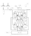
CAES発電装置1は、風力発電装置2(この第1実施形態では2台の風車を備えた発電設備)の出力変動を平準化する。CAES発電装置1は、モータ3a〜3c、圧縮機4a〜4c、圧縮空気貯蔵用のタンク5a〜5c、注入側弁6a〜6e、膨張機7a〜7c、排出側弁8a〜8e、発電機9a〜9c、出力センサ10、圧力センサ11a〜11c、及び制御装置12を備える。制御手段22は、注入側弁6a〜6e、排出側弁8a〜8e、出力センサ10、圧力センサ11a〜11c、及び制御装置12を備える。
The
風力発電装置2により発電された電力は、互いに電気的に並列に接続されたモータ3a〜3cに供給される。この電力によりモータ3a〜3cが駆動される。モータ3a〜3cは、圧縮機4a〜4cに機械的にそれぞれ接続されている。圧縮機4a〜4cは、モータ3a〜3cを駆動させることでそれぞれ作動する。圧縮機4a〜4cは、吸引した空気を圧縮し、タンク5a〜5cへ圧送する。これにより、タンク5a〜5cに圧縮空気としてエネルギーを蓄積できる。
The electric power generated by the
本実施形態では、3基のタンク5a〜5cが設けられている。相対的に小容量のタンク(小容量タンク)5a,5bが2基、及び相対的に大容量のタンク(大容量タンク)5cが1基である。小容量タンク5a,5bは、5分から20分程度(1時間未満)持続して空気を貯蔵又は発電できる容量である。大容量タンク5cは、1〜8時間程度(1時間以上)持続して空気を貯蔵又は発電できる容量である。風力や太陽光を用いて発電される変動電力に対応するには、小容量タンクと大容量タンクの閾値を1時間程度に設定するのが望ましい。小容量タンク5a,5bには、空気供給路を介してモータ3a,3b及び圧縮機4a,4bがそれぞれ1つずつ接続されている。大容量タンク5cには、全てのモータ3a〜3c及び圧縮機4a〜4cが空気供給路を介して接続されている。本発明に係るCAES発電装置1では、少なくとも2基の容量の異なるタンク5a〜5cが、設けられていればよい。従って、例えば小容量タンク5a,5bは、1基であってもよいし、又は3基以上であってもよい。大容量タンク5cは、2基以上であってもよい。このように、小容量タンク5a,5b及び大容量タンク5cの数について、少なくとも各1基設けられていればよく、特にその数を限定しないことは後述する第2から第5実施形態においても同様である。また、小容量タンクと大容量タンクの容量についても明確な区切りがある訳ではなく、相対的に大容量なタンクと小容量なタンクがあればよい。さらに、小容量タンク5a,5bは同容量である必要はなく、後述するようにタンク5aを優先的に制御する場合は、タンク5aをタンク5bより小容量のものとすることもできる。
In the present embodiment, three tanks 5a to 5c are provided. There are two relatively small tanks (small capacity tanks) 5a and 5b, and one relatively large capacity tank (large capacity tank) 5c. The small-capacity tanks 5a and 5b have a capacity capable of storing air or generating power continuously for about 5 to 20 minutes (less than 1 hour). The large-capacity tank 5c has a capacity capable of storing or generating power for about 1 to 8 hours (1 hour or more). In order to cope with the fluctuating power generated using wind power or sunlight, it is desirable to set the threshold values of the small capacity tank and the large capacity tank to about 1 hour. One motor 3a and 3b and one compressor 4a and 4b are connected to the small capacity tanks 5a and 5b, respectively, via an air supply path. All the motors 3a to 3c and the compressors 4a to 4c are connected to the large capacity tank 5c through an air supply path. In the
大容量タンク5cには、岩塩層空洞、休鉱山の坑道、下水配管・縦孔などの地下空洞や、水中に沈めた袋状の容器を使用してもよい。密閉性のよい坑道であればタンク5a〜5cとして利用でき、設備コストが極めて低減される。一般に、CAES設備の製造にあたり、コスト増加の要因は大容量のタンク5cの製造であることが多い。従って、大容量のタンク5cに代替するものとして密閉性のよい坑道を使用することで、大幅に設備コストを低減できる。大容量のタンク5cに限らず、小容量のタンク5a,5bとして休鉱山の坑道を利用する場合でも同様にコスト低減には有効である。また、適切な維持管理に多年に亘って維持費を必要とする坑道(又は廃坑道)の有効利用策としても期待できる。 The large-capacity tank 5c may be a salt layer cavity, a tunnel of a closed mine, an underground cavity such as a sewage pipe or a vertical hole, or a bag-like container submerged in water. If it is a tunnel with good airtightness, it can be used as the tanks 5a to 5c, and the equipment cost is extremely reduced. In general, in the manufacture of CAES equipment, the cause of the increase in cost is often the manufacture of a large-capacity tank 5c. Therefore, by using a well-sealed tunnel as an alternative to the large-capacity tank 5c, the equipment cost can be greatly reduced. Even in the case of using a closed mine tunnel as a small capacity tank 5a, 5b as well as the large capacity tank 5c, it is also effective for cost reduction. Moreover, it can also be expected as an effective utilization measure of a tunnel (or abandoned tunnel) that requires maintenance costs for many years for appropriate maintenance.
圧縮機4a〜4cとタンク5a〜5cとの間の空気供給路には、注入側弁6a〜6eが設けられている。この注入側弁6a〜6eにより、各圧縮機4a〜4cからいずれのタンク5a〜5cに圧縮空気を供給するか切り替える。 Injection side valves 6a to 6e are provided in the air supply path between the compressors 4a to 4c and the tanks 5a to 5c. By these injection side valves 6a to 6e, the tanks 5a to 5c to which compressed air is supplied are switched from the compressors 4a to 4c.
小容量タンク5a,5bは、空気供給路を介して膨張機7a,7b及び発電機9a,9bにそれぞれ接続されている。大容量タンク5cは、空気供給路を介して全ての膨張機7a〜7c及び発電機9a〜9cに接続されている。 The small-capacity tanks 5a and 5b are connected to the expanders 7a and 7b and the generators 9a and 9b through air supply paths, respectively. The large capacity tank 5c is connected to all of the expanders 7a to 7c and the generators 9a to 9c through an air supply path.
タンク5a〜5cに蓄積された圧縮空気は、膨張機7a〜7cに供給される。この圧縮空気により膨張機7a〜7cは駆動される。タンク5a〜5cと膨張機7a〜7cとの間の空気供給路には、排出側弁8a〜8eが設けられている。この排出側弁8a〜8eにより、各タンク5a〜5cからいずれの膨張機7a〜7cに圧縮空気を供給するか切り替える。膨張機7a〜7cは、互いに電気的に並列に接続されており、発電機9a〜9cに機械的にそれぞれ接続されている。発電機9a〜9cは、膨張機7a〜7cを駆動させることで作動し、発電する。 The compressed air accumulated in the tanks 5a to 5c is supplied to the expanders 7a to 7c. The expanders 7a to 7c are driven by the compressed air. Discharge-side valves 8a to 8e are provided in the air supply path between the tanks 5a to 5c and the expanders 7a to 7c. By these discharge side valves 8a to 8e, it is switched which of the expanders 7a to 7c is supplied with compressed air from the respective tanks 5a to 5c. The expanders 7a to 7c are electrically connected to each other in parallel, and are mechanically connected to the generators 9a to 9c, respectively. The generators 9a to 9c operate by driving the expanders 7a to 7c to generate electric power.
出力センサ10は風力発電装置2の出力を測定する。CAES発電装置1の入力部分における電力等を測定してもよいし、風力発電装置2から出力信号として受け取ってもよい。圧力センサ11a〜11cは、タンク5a〜5c内の圧力をそれぞれ測定する。制御装置12は、注入側弁6a〜6e及び排出側弁8a〜8eと電気的に接続されている。制御装置12により、出力センサ10及び圧力センサ11a〜11cの測定値に基づいて、注入側弁6a〜6e及び排出側弁8a〜8eの開閉が制御される。
The
なお、風力発電装置2とモータ3a〜3cの間、及び系統とモータ9a〜9cとの間には、トランス、インバータ、継電器、遮断機等の電力機器(図示省略)が配置されている。この実施形態では圧力センサ11a〜11cを用いたが、タンク内の空気残量を検出することができればよく、圧力センサ以外の検出器を設けてもよい。
In addition, between the
また、本第1実施形態における圧縮機4a〜4c、膨張機7a〜7cは同じ容量のものを使用してもよいし、圧縮機4c>圧縮機4b>圧縮機4a、膨張機7c>膨張機7b>膨張機7aの順に大きさを変えてもよい。一般的に言って、圧縮機・膨張機は、容量が小さいほど応答性がよく、容量が大きいほど効率が高い。これらの有利な点を活かすため、短周期変動への対応には、相対的に容量が小さい圧縮機・膨張機の使用が好ましく、長周期変動への対応には、相対的に容量が大きい圧縮機・膨張機の使用が好ましい。 The compressors 4a to 4c and the expanders 7a to 7c in the first embodiment may have the same capacity, or the compressor 4c> the compressor 4b> the compressor 4a, the expander 7c> the expander. The size may be changed in the order of 7b> expander 7a. Generally speaking, the smaller the capacity, the better the response of the compressor / expander, and the higher the capacity, the higher the efficiency. In order to take advantage of these advantages, it is preferable to use a compressor / expander with a relatively small capacity to cope with short cycle fluctuations, and a compression with a relatively large capacity to deal with long period fluctuations. Use of an expander / expander is preferred.
このように、CAES発電装置1は、圧縮空気によるエネルギーを利用する。従って、環境に有害な物質を排出しない点で有効である。また、エネルギーの蓄積に2次電池やキャパシタを使用していない。2次電池やキャパシタは使用に際して、不利な点がある。2次電池は廃棄コストが高く、サイクル寿命(充放電のサイクル数)が短い。種類によっては、充電率、電圧の監視、及び温度管理が必要となる。キャパシタはエネルギー密度が低く、高価である。
Thus, the
次に、CAES発電装置1の平準化方法及びその制御方法について詳細に説明する。
Next, the leveling method and control method of the
図2は、風力発電装置2の出力変動の1日の推移例(自然エネルギーによる変動出力)と、平準化の目標とする2つの曲線(長周期需要曲線及び短周期基準曲線)を示している。風力発電装置2の出力変動は、出力センサ10によって測定され、制御装置12によって長周期変動と短周期変動とに区別して認識される。ここでは、長周期とは数時間単位の変動を示し、短周期とは数分単位の変動を示す。秒単位の変動についてはフィルタ等により除去する。短周期の変動は、主に小容量タンク5a,5bを用いて平準化する。長周期の変動に対しては、主に大容量タンク5cを用いて需要曲線に応じた電力を出力する。大容量タンク5cと比較して、小容量タンク5a,5bを利用した発電は、発電に適した圧力になるまで昇圧するのにかかる時間が短く、常に適正な圧縮空気量を蓄えた状態で発電できるので応答性がよい。従って、変動周期の長さに応じて容量の異なるタンク5a〜5cを使用することで、特に短周期変動に対して追従性よく平準化できる。
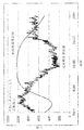
FIG. 2 shows a daily transition example of the output fluctuation of the wind power generator 2 (fluctuating output due to natural energy) and two curves (a long-period demand curve and a short-period reference curve) targeted for leveling. . The output fluctuation of the
長周期変動と短周期変動のうち、まず、長周期変動に対する制御方法について説明する。 Of the long-period fluctuation and the short-period fluctuation, first, a control method for the long-period fluctuation will be described.
図3は、長周期変動に対する制御方法を示すフローチャートである。図3に示すように、長周期変動に対して発電を行う場合と蓄電を行う場合がある。長周期変動に対して発電を行う場合、大容量タンク5cの圧縮空気を利用して、膨張機7cを駆動して発電する。この際、排出側弁8cを開く。長周期変動に対して蓄電を行う場合、圧縮機4cを使用して大容量タンク5cに圧縮空気を充填する。この際、注入側弁6cを開く。この場合、圧縮機4a,4bは使用しなくてもよいが、急速充填をする場合には圧縮機4a,4bも使用してもよい。同様に、膨張機7a,7bは使用しなくてもよいが、放電電力を増加させる必要がある場合には膨張機7a,7bを使用してもよい。 FIG. 3 is a flowchart showing a control method for long-period fluctuation. As shown in FIG. 3, there are cases where power generation is performed and power storage is performed against long-period fluctuations. When power generation is performed for long-period fluctuation, the expander 7c is driven using the compressed air in the large capacity tank 5c to generate power. At this time, the discharge side valve 8c is opened. When power storage is performed for long-period fluctuation, the compressor 4c is used to fill the large capacity tank 5c with compressed air. At this time, the injection side valve 6c is opened. In this case, the compressors 4a and 4b may not be used, but the compressors 4a and 4b may also be used when rapid filling is performed. Similarly, the expanders 7a and 7b may not be used, but the expanders 7a and 7b may be used when the discharge power needs to be increased.
制御装置12は、発電と蓄電の切り替えや圧縮機・膨張機の回転数制御を行う。この切り替えの判断は、図2の長周期需要曲線に基づいて行われる。風力発電装置2の出力(出力センサ10の測定値)が、長周期需要曲線以上である場合には蓄電を行う。一方、長周期需要曲線よりも下にある場合には発電を行う。このように、出力センサ10の出力を、目標とする長周期需要曲線に近づけるような制御を行う。ここで、長周期需要曲線は、例えば、長年にわたって蓄積されてきた過去の電力使用量データに基づいて、当日の曜日や気象条件等によって決定する。
The control device 12 performs switching between power generation and power storage and rotation speed control of the compressor / expander. This switching decision is made based on the long-period demand curve of FIG. When the output of the wind power generator 2 (measured value of the output sensor 10) is equal to or greater than the long-period demand curve, the battery is charged. On the other hand, when it is below the long-period demand curve, power is generated. In this way, control is performed so that the output of the
次に、短周期変動に対する制御方法ついて説明する。 Next, a control method for short period fluctuation will be described.
図4は、短周期変動に対する制御方法を示すフローチャートである。長周期変動の場合と同様に、短周期変動に対して、発電を行う場合と蓄電を行う場合がある。短周期変動に対して発電を行う場合、例えば、小容量タンク5aの圧縮空気を利用して、膨張機7aを回転させて発電する。この際、排出側弁8aを開き、排出側弁8dを閉じる。短周期変動に対して蓄電を行う場合、例えば、圧縮機4aを使用して小容量タンク5aに圧縮空気を充填する。この際、注入側弁6aを開き、注入側弁6dを閉じる。 FIG. 4 is a flowchart showing a control method for short-cycle fluctuations. As in the case of long-period fluctuation, there are cases where power generation is performed and power storage is performed for short-period fluctuation. When power generation is performed with respect to short cycle fluctuations, for example, power is generated by rotating the expander 7a using compressed air in the small capacity tank 5a. At this time, the discharge side valve 8a is opened and the discharge side valve 8d is closed. When power storage is performed for short cycle fluctuations, for example, the compressor 4a is used to fill the small capacity tank 5a with compressed air. At this time, the injection side valve 6a is opened and the injection side valve 6d is closed.
制御装置12は、長周期変動に対する場合と同様に、短周期変動に対しても発電と蓄電の切り替えを行う。この切り替えの判断は、図2に破線で示される短周期基準曲線に基づいて行われる。風力発電装置2の出力(出力センサ10の測定値)が、短周期基準曲線以上である場合に蓄電を行う。一方、短周期基準曲線よりも下にある場合には発電を行う。このように風力発電装置2の出力(出力センサ10の測定値)が、目標とする短周期基準曲線に近づくように平準化を行う。ここで、短周期基準曲線は、例えば直前の所定時間における平均値に基づいて決定する。 The control device 12 switches between power generation and power storage for short cycle fluctuations as well as for long cycle fluctuations. This switching determination is made based on the short cycle reference curve indicated by a broken line in FIG. When the output of the wind power generator 2 (measured value of the output sensor 10) is equal to or higher than the short cycle reference curve, the battery is charged. On the other hand, when it is below the short cycle reference curve, power is generated. In this way, leveling is performed so that the output of the wind turbine generator 2 (measured value of the output sensor 10) approaches the target short period reference curve. Here, the short cycle reference curve is determined based on, for example, an average value in a predetermined time immediately before.
圧縮機4a〜4c及び膨張機7a〜7cには、一般に、ターボ式とスクリュ式、スクロール式及びロータリー式に代表される容積式の2つの種類がある。ここで、小容量タンク5a,5bに接続される圧縮機4a,4bと膨張機7a,7bは共に、容積式であることが好ましい。また、大容量タンク5cに接続される圧縮機4c及び膨張機7cも、共に容積式が好ましい。この構成により、ターボ式ではなく容積式を採用することで回転数制御を行うことができ、安定した発電を行うことができる。また、容積式は、ターボ式に比べて小流量(低回転数)でも効率が落ちないので、タンクに蓄えられた圧縮空気量が少ない場合でも安定した発電ができ、制御範囲を拡張できる。特に、小容量タンク5a,5bに接続される圧縮機4a,4b及び膨張機7a,7bは短周期変動を平準化するため、良好な追従性が必要であり、容積式であることが特に有効である。なお、本実施形態の場合、圧縮機4a〜4c及び膨張機7a〜7cには、容積式の中でも比較的大容量なものに適しているスクリュ式(詳しくは、ツインスクリュ式)の圧縮機および膨張機を使用している。 The compressors 4a to 4c and the expanders 7a to 7c are generally classified into two types, that is, a positive displacement type represented by a turbo type, a screw type, a scroll type, and a rotary type. Here, it is preferable that the compressors 4a and 4b and the expanders 7a and 7b connected to the small capacity tanks 5a and 5b are positive displacement type. The compressor 4c and the expander 7c connected to the large-capacity tank 5c are preferably positive displacement types. With this configuration, the rotational speed control can be performed by adopting a positive displacement type instead of a turbo type, and stable power generation can be performed. In addition, the positive displacement type does not decrease the efficiency even at a small flow rate (low rotation speed) compared to the turbo type, so that stable power generation can be performed even when the amount of compressed air stored in the tank is small, and the control range can be expanded. In particular, the compressors 4a and 4b and the expanders 7a and 7b connected to the small-capacity tanks 5a and 5b level out short-cycle fluctuations, and therefore require good followability. It is. In the case of the present embodiment, the compressors 4a to 4c and the expanders 7a to 7c include screw type compressors (specifically, twin screw type compressors) that are suitable for relatively large volumes among positive displacement types, and An expander is used.
上記構成以外にも、大容量タンク5cに接続される圧縮機4c及び膨張機7cは、共にターボ式であり、一方、小容量タンク5a,5bに接続される圧縮機4a,4b及び膨張機7a,7bは、共に容積式であってもよい。この構成により、既設のCAES設備(タンク5c、圧縮機4c、膨張機7c)に小容量の容積式圧縮機4a,4b、容積式膨張機7a,7b、及びタンク5a,5bを追加して設置することができる。これには、既設のCAES設備は一般にターボ式であり、この既設の設備をそのまま利用できる利点がある。また、新設の場合であっても、大容量タンク5cに接続される圧縮機4c及び膨張機7cは長周期変動に対応することを主目的としているので、ターボ式でも対応することができる。 Besides the above configuration, the compressor 4c and the expander 7c connected to the large capacity tank 5c are both turbo type, while the compressors 4a and 4b and the expander 7a connected to the small capacity tanks 5a and 5b. , 7b may be positive displacement. With this configuration, small-capacity positive displacement compressors 4a and 4b, positive displacement expanders 7a and 7b, and tanks 5a and 5b are added to the existing CAES equipment (tank 5c, compressor 4c, and expander 7c). can do. This has an advantage that the existing CAES equipment is generally a turbo type, and the existing equipment can be used as it is. Further, even in the case of a new installation, the compressor 4c and the expander 7c connected to the large-capacity tank 5c are mainly intended to cope with long-period fluctuations, so that the turbo type can also be handled.
短周期の変動電力に対しては小型の圧縮機4a,4b及び膨張機7a,7bを使用し、長周期の変動電力に対しては大型の圧縮機5c及び膨張機7cを使用することが好ましい。この構成により、小型の圧縮機4a,4b及び膨張機7a,7bの方が入力に対する応答性が良いので、短周期変動に対する追従性が向上する。 It is preferable to use small compressors 4a and 4b and expanders 7a and 7b for short-cycle variable power, and use large compressors 5c and expander 7c for long-cycle variable power. . With this configuration, the small compressors 4a and 4b and the expanders 7a and 7b have better responsiveness to input, so that followability to short cycle fluctuations is improved.
短周期変動を平準化する場合、制御装置12は、出力センサ10を使用して測定する短周期の変動電力の振幅に基づいて、圧縮機4a,4b及び膨張機7a,7bの台数制御と回転数制御を行う。ただし、回転数制御を行う場合、圧縮機4a,4b及び膨張機7a,7bは、容積式である必要がある。例えば、台数制御に関しては、小容量タンク5aに接続された圧縮機4a及び膨張機7aを基本的に使用する。しかし、圧縮機4a及び膨張機7aでは平準化しきれない程大きく短周期基準曲線から変動電力の振幅が乖離した場合は、運転台数を増加する(圧縮機4b又は膨張機7bを合わせて使用する)。この際、圧縮機4a〜4cと膨張機7a〜7cの動作に合わせて注入側弁6a〜6e及び排出側弁8a〜8eを制御する。特に急激な変動に対応する必要がある場合には、全ての圧縮機4a〜4c又は全ての膨張機7a〜7cを同時に運転してもよい。このようにすることで、より広範な平準化が可能となる。回転数制御に関しても同様に、平準化の程度に応じて圧縮機4a〜4c及び膨張機7a〜7cの回転数(出力)を増減させ、最適な平準化を行う。
When leveling the short cycle fluctuation, the control device 12 controls the number of compressors 4a and 4b and the expanders 7a and 7b and rotates them based on the amplitude of the short cycle fluctuation power measured using the
本実施形態においては、小容量タンク5a,5bが2基設けられている。従って、制御装置12は、圧力センサ11a〜11cの測定値に基づいて、小容量タンク5a,5bのいずれを使用するのかをさらに判断する。図4は、特に小容量タンク5aをメインタンク5aと設定した場合の制御を示している。 In this embodiment, two small-capacity tanks 5a and 5b are provided. Therefore, the control device 12 further determines which of the small capacity tanks 5a and 5b is to be used based on the measurement values of the pressure sensors 11a to 11c. FIG. 4 shows the control when the small tank 5a is set as the main tank 5a.
図4を参照して、短周期変動に対して発電を行う場合、小容量タンク5aが発電に適した充填量であれば小容量タンク5aを使用する(排出側弁8aを開き、排出側弁8dを閉じる)。小容量タンク5aが空であるか充填量が低い場合及び小容量タンク5bの充填量が十分である場合、小容量タンク5bを使用する(排出側弁8bを開き、排出側弁8eを閉じる)。小容量タンク5a,5bが共に空であるか充填量が低い場合で、かつ大容量タンクの充填量が十分である場合は、止むを得ず大容量タンク5cを使用する(排出側弁8c〜eのいずれかを開き、その他の排出側弁を閉じる)。 Referring to FIG. 4, when power generation is performed with respect to short cycle fluctuations, the small capacity tank 5 a is used if the small capacity tank 5 a is a filling amount suitable for power generation (the discharge side valve 8 a is opened and the discharge side valve is opened). Close 8d). When the small-capacity tank 5a is empty or the filling amount is low and when the filling amount of the small-capacity tank 5b is sufficient, the small-capacity tank 5b is used (the discharge side valve 8b is opened and the discharge side valve 8e is closed). . When both the small capacity tanks 5a and 5b are empty or the filling amount is low, and the filling amount of the large capacity tank is sufficient, the large capacity tank 5c is unavoidably used (the discharge side valves 8c to 8c). Open any of e and close the other exhaust valves).
なお、小容量タンク5aまたは5bの空気量が低い場合、適宜、大容量タンク5cから小容量タンク5a,5bに圧縮空気を差圧充填してもよい。これを示したのが、図5である。大容量タンク5cは、小容量タンク5a,5bに圧縮空気を供給できるように、タンク間空気供給弁21a,21bを介して接続されている。タンク間空気供給弁21a,21bとしては、小容量タンクと大容量タンクの圧力差に基づいて開閉制御される電磁弁や圧力差で自動開閉する差圧制御弁を用いることができる。このように、大容量タンク5cから小容量タンク5a,5bに空気を差圧充填する構成とできることは、後述する第2から第5実施形態においても同様である。 When the amount of air in the small capacity tank 5a or 5b is low, compressed air may be filled with the compressed air from the large capacity tank 5c to the small capacity tanks 5a and 5b as appropriate. This is shown in FIG. The large capacity tank 5c is connected via inter-tank air supply valves 21a and 21b so that compressed air can be supplied to the small capacity tanks 5a and 5b. As the inter-tank air supply valves 21a and 21b, an electromagnetic valve that is controlled to open and close based on a pressure difference between a small capacity tank and a large capacity tank or a differential pressure control valve that automatically opens and closes based on the pressure difference can be used. As described above, the configuration in which the large-capacity tank 5c is filled with the differential pressure of the small-capacity tanks 5a and 5b is the same in the second to fifth embodiments described later.
短周期変動に対して蓄電を行う場合、小容量タンク5aが満タンでなければ小容量タンク5aに圧縮空気を充填する(注入側弁6aを開き、注入側弁6dを閉じる)。小容量タンク5aが満タンの場合で小容量タンク5bが満タンでない場合、小容量タンク5bに圧縮空気を充填する(注入側弁6bを開き、注入側弁6eを閉じる)。小容量タンク5a,5bが共に満タンの場合、大容量タンク5cに圧縮空気を充填する(注入側弁6cを開く)。 When power storage is performed for short-cycle fluctuations, if the small capacity tank 5a is not full, the small capacity tank 5a is filled with compressed air (the injection side valve 6a is opened and the injection side valve 6d is closed). When the small capacity tank 5a is full and the small capacity tank 5b is not full, the small capacity tank 5b is filled with compressed air (the injection side valve 6b is opened and the injection side valve 6e is closed). When both the small capacity tanks 5a and 5b are full, the large capacity tank 5c is filled with compressed air (the injection side valve 6c is opened).
このようにして、仮に小容量タンク5a,5bが全て空になった場合でも、大容量タンク5cの圧縮空気を使用して膨張機7a,7bを駆動することができる。従って、短周期変動が平準化されなくなるという場合を回避できる。 Thus, even if the small capacity tanks 5a and 5b are all emptied, the expanders 7a and 7b can be driven using the compressed air of the large capacity tank 5c. Therefore, it is possible to avoid a case where short cycle fluctuations are not leveled.
これに代えて、小容量タンクに優先順位の高いメインタンクを設定しない方法であってもよい。図6A及び図6Bは、小容量タンク5a,5bを交互に使用する制御方法を示している。 Instead of this, a method in which a main tank having a high priority is not set in the small-capacity tank may be used. 6A and 6B show a control method in which the small capacity tanks 5a and 5b are used alternately.
短周期変動に対して発電を行う場合、制御装置12により記憶されたフラグに基づいて処理1〜4を選択する。処理1では、小容量タンク5aが空(または圧縮空気量が少ない場合。以下同じ。)でない場合、小容量タンク5aを使用する(排出側弁8aを開き、排出側弁8dを閉じる)。小容量タンク5aが空である場合及び小容量タンク5bが空でない場合、フラグ=2に変更し、小容量タンク5bの使用を開始する(排出側弁8bを開き、排出側弁8eを閉じる)。小容量タンク5a,5bが共に空の場合、フラグ=3に変更し、大容量タンク5cを使用する(排出側弁8d,8eのいずれかを開き、その他の排出側弁を閉じる)。処理2では、小容量タンク5bが空でない場合、小容量タンク5bを使用する(排出側弁8bを開き、排出側弁8eを閉じる)。小容量タンク5bが空である場合及び小容量タンク5aが空でない場合、フラグ=1に変更し、小容量タンク5aの使用を開始する(排出側弁8aを開き、排出側弁8dを閉じる)。小容量タンク5b,5aが共に空の場合、フラグ=4に変更し、大容量タンク5cを使用する(排出側弁8d,8eいずれかを開き、その他の排出側弁を閉じる。この場合、長周期変動に対する制御は、排出側弁8cを開いておくことで引き続き膨張機7cが担う。)。処理3では、小容量タンク5bが空でない場合、フラグ=2に変更し、小容量タンク5bを使用する(排出側弁8bを開き、排出側弁8eを閉じる)。小容量タンク5bが空である場合、大容量タンク5cを使用する(排出側弁8a、8bを閉じ、排出側弁8d又は/及び8eを開く)。処理4では、小容量タンク5aが空でない場合、フラグ=1に変更し、小容量タンク5aを使用する(排出側弁8aを開き、排出側弁8dを閉じる)。小容量タンク5aが空である場合、大容量タンク5cを使用する(排出側弁8a、8bを閉じ、排出側弁8d又は/及び8eを開く)。
When power generation is performed with respect to the short cycle fluctuation, the
短周期変動に対して蓄電を行う場合、制御装置12により記憶されたフラグにより圧縮空気を充填するタンク5a〜5cを選択する。フラグ=1又はフラグ=3の場合、小容量タンク5bが満タンでなければ小容量タンク5bに圧縮空気を充填する(注入側弁6bを開き、その他の弁を閉じる)。小容量タンク5bが満タンである場合で小容量タンク5aが満タンでない場合、小容量タンク5aに圧縮空気を充填する(注入側弁6aを開き、その他の弁を閉じる)。小容量タンク5b,5aが共に満タンの場合、大容量タンク5cに圧縮空気を充填する(注入側弁6d,6eのいずれかを開き、その他の弁を閉じる)。フラグ=2又はフラグ=4の場合、小容量タンク5aが満タンでなければ小容量タンク5aに圧縮空気を充填する(注入側弁6aを開き、その他の弁を閉じる)。小容量タンク5aが満タンである場合で小容量タンク5bが満タンでない場合、小容量タンク5bに圧縮空気を充填する(注入側弁6bを開き、その他の弁を閉じる)。小容量タンク5a,5bが共に満タンの場合、大容量タンク5cに圧縮空気を充填する(注入側弁6d,6eのいずれかを開き、その他の弁を閉じる)。 When power storage is performed for short-cycle fluctuations, the tanks 5a to 5c filled with compressed air are selected by the flag stored by the control device 12. When the flag = 1 or the flag = 3, if the small capacity tank 5b is not full, the small capacity tank 5b is filled with compressed air (the injection side valve 6b is opened and the other valves are closed). When the small capacity tank 5b is full and the small capacity tank 5a is not full, the small capacity tank 5a is filled with compressed air (the injection side valve 6a is opened and the other valves are closed). When both the small capacity tanks 5b and 5a are full, the large capacity tank 5c is filled with compressed air (open one of the injection side valves 6d and 6e and close the other valves). When the flag = 2 or the flag = 4, if the small capacity tank 5a is not full, the small capacity tank 5a is filled with compressed air (the injection side valve 6a is opened and the other valves are closed). When the small capacity tank 5a is full and the small capacity tank 5b is not full, the small capacity tank 5b is filled with compressed air (the injection side valve 6b is opened and the other valves are closed). When both the small-capacity tanks 5a and 5b are full, the large-capacity tank 5c is filled with compressed air (open one of the injection side valves 6d and 6e and close the other valves).
このように、小容量タンク5a,5bを交互に使用することで、小容量タンク5a,5bのいずれかの使用頻度が高くならないようにする。従って、小容量タンク5a,5bのいずれかのみが使用劣化することを防止できる。また、メインタンク5aを設定した場合と同様に、仮に小容量タンク5a,5bが全て空の場合でも、大容量タンク5cの圧縮空気を使用して膨張機7a,7bを駆動する。従って、短周期変動が平準化されなくなるという場合を回避できる。なお、小容量タンク5a,5bを交互に使用するだけでなく、両方を同時に使用すれば、より広範囲の変動を平滑化することができる。 As described above, by alternately using the small capacity tanks 5a and 5b, the frequency of use of either of the small capacity tanks 5a and 5b is prevented from increasing. Therefore, it is possible to prevent only one of the small capacity tanks 5a and 5b from being deteriorated in use. Similarly to the case where the main tank 5a is set, even if the small capacity tanks 5a and 5b are all empty, the expanders 7a and 7b are driven using the compressed air of the large capacity tank 5c. Therefore, it is possible to avoid a case where short cycle fluctuations are not leveled. In addition to using the small-capacity tanks 5a and 5b alternately, a wider range of fluctuations can be smoothed by using both simultaneously.
メインタンク5aを設定する場合又はしない場合のいずれの方法においても、タンク5a〜5cが許容圧力を超えないように図示しない安全弁が設けられている。安全弁は、許容圧力を超える恐れがある場合、タンク5a〜5cに貯蔵した圧縮空気を許容圧力以下で大気に開放するように予め設定されている。すべてのタンク5a〜5cが満タンの場合で、かつ平滑化のために風力発電装置2の電力を消費する必要がある場合は、いずれかの圧縮機4a〜4cを駆動し、発生した空気を大気放出すればよい。
In either method of setting or not setting the main tank 5a, a safety valve (not shown) is provided so that the tanks 5a to 5c do not exceed the allowable pressure. The safety valve is set in advance to release the compressed air stored in the tanks 5a to 5c to the atmosphere below the allowable pressure when there is a risk of exceeding the allowable pressure. When all the tanks 5a to 5c are full and it is necessary to consume the power of the
メインタンク5aを設定する場合又はしない場合のいずれの方法においても小容量タンク5a,5bの使用に関しては、完全に空になるまで使用しなくてもよい。小容量タンク5a,5bの残存空気量が減少すると、膨張機7a,7bに供給される空気量が減少し、十分な発電量を確保できなくなる場合がある。しかし、このように残存空気量に一定の閾値を設けることで、発電に必要な一定以上の空気供給量(又は圧力)を維持した状態で圧縮空気を使用できる。 Regardless of whether the main tank 5a is set or not, the small-capacity tanks 5a and 5b need not be used until they are completely emptied. When the amount of remaining air in the small capacity tanks 5a and 5b decreases, the amount of air supplied to the expanders 7a and 7b decreases, and it may not be possible to secure a sufficient power generation amount. However, by providing a certain threshold value for the remaining air amount in this way, compressed air can be used in a state where an air supply amount (or pressure) above a certain level necessary for power generation is maintained.
本発明によれば、長周期と短周期の各変動電力に対して容量の異なるタンクをそれぞれ使用しているため、長周期と短周期の変動電力の両方を効率的に平準化し、需要電力に応じた電力を出力することができる。また、必要に応じて短周期変動に対しても大容量タンク5cを使用することで、小容量タンク5a,5bが全て空の場合でも、平準化を行うことができる。こういう場合を避けるために、小容量タンク5a,5bの空気残量が減った場合、大容量タンク5cから小容量タンク5a,5bに差圧充填することが望ましい。 According to the present invention, since the tanks having different capacities are used for the long-cycle and short-cycle fluctuation powers, both the long-cycle and short-cycle fluctuation powers are efficiently leveled and the demand power is The corresponding power can be output. Further, by using the large-capacity tank 5c for short cycle fluctuations as necessary, leveling can be performed even when the small-capacity tanks 5a and 5b are all empty. In order to avoid such a case, it is desirable to fill the differential pressure from the large capacity tank 5c to the small capacity tanks 5a and 5b when the remaining amount of air in the small capacity tanks 5a and 5b decreases.
(第2実施形態)
図7は、第2実施形態のCAES発電装置1を示している。本実施形態のCAES発電装置1は、1基の小容量タンク5aに各2台(複数)の圧縮機4a,4bと膨張機7a,7bが接続されていることに関する部分以外の構成は図1の第1実施形態と同様である。従って、図1に示した構成と同様の部分については同様の符号を付して説明を省略する。
(Second Embodiment)
FIG. 7 shows a
図7を参照して、第2実施形態のCAES発電装置1は、小容量タンク5aと大容量タンク5bがそれぞれ1基設けられている。小容量タンク5aには、モータ3a,3b、圧縮機4a,4b、膨張機7a,7b、及び発電機9a,9bがそれぞれ接続されている。大容量タンク5bには、全てのモータ3a〜3c、圧縮機4a〜4c、膨張機7a〜7c、及び発電機9a〜9cがそれぞれ接続されている。この構成により、モータ3a〜3c、圧縮機4a〜4c、膨張機7a〜7c、及び発電機9a〜9cが各タンクに対して各1台のみ設けられた場合と比較して、小容量タンク5aに急速に圧縮空気を蓄積することができる。また、小容量タンクが1つでよいので設備コストと設置面積を抑えることができる。
Referring to FIG. 7, the
CAES発電装置1の平準化方法及びその制御方法に関しては、長周期変動を平準化して電力需要に合った電力を出力する場合は、第2実施形態も第1実施形態と同様である。
Regarding the leveling method of the
短周期変動を平準化する場合、制御装置12は、短周期基準曲線に基づいて、圧縮機4a〜4c及び膨張機7a〜7cの台数制御と回転数制御を行う。小容量タンク5aに圧縮空気を充填し、蓄電する場合、圧縮機4a,4bを1台又は2台使用できる。例えば、圧縮機4aを1台使用する場合、注入側弁6a,6dを開き、少なくとも注入側弁6eを閉じる。また、圧縮機4a,4bを2台使用する場合、注入側弁6a,6b,6d,6eを開き、少なくとも注入側弁6fを閉じる。このように、使用する圧縮機4a,4bの台数を調整し、小容量タンク5aへの圧縮空気の充填速度・充填量を調整できる。同様に、小容量タンク5aの圧縮空気を使用して発電する場合、膨張機7a,7bに関して、1台又は2台使用できる。例えば、1台の膨張機7a(発電機9a)を使用する場合、排出側弁8a,8dを開き、排出側弁8eと必要に応じたその他の排出側弁を閉じる。また、2台の膨張機7a,7b(発電機9a,9b)を使用する場合、排出側弁8a,8b,8d,8eを開き、少なくとも排出側弁8fを閉じる。このように、使用する膨張機7a,7b(発電機9a,9b)の台数を調整し、発電する電力量を調整できる。また、ここで記載した部分以外の短周期変動の平準化方法及び制御は、第2実施形態も第1実施形態と同様である。 When leveling the short cycle variation, the control device 12 performs the number control and the rotation speed control of the compressors 4a to 4c and the expanders 7a to 7c based on the short cycle reference curve. When the small capacity tank 5a is filled with compressed air and stored, one or two compressors 4a and 4b can be used. For example, when one compressor 4a is used, the injection side valves 6a and 6d are opened, and at least the injection side valve 6e is closed. When two compressors 4a and 4b are used, the injection side valves 6a, 6b, 6d and 6e are opened, and at least the injection side valve 6f is closed. Thus, the number of compressors 4a and 4b to be used can be adjusted, and the filling speed and filling amount of the compressed air into the small capacity tank 5a can be adjusted. Similarly, when generating electric power using the compressed air of the small capacity tank 5a, one or two of the expanders 7a and 7b can be used. For example, when using one expander 7a (generator 9a), the discharge side valves 8a and 8d are opened, and the discharge side valve 8e and other discharge side valves as necessary are closed. When two expanders 7a and 7b (generators 9a and 9b) are used, the discharge side valves 8a, 8b, 8d and 8e are opened, and at least the discharge side valve 8f is closed. In this way, the amount of power to be generated can be adjusted by adjusting the number of expanders 7a and 7b (generators 9a and 9b) to be used. In addition, the second embodiment is the same as the first embodiment in the short-period fluctuation leveling method and control other than those described here.
(第3実施形態)
図8は、第3実施形態のCAES発電装置1を示している。本実施形態のCAES発電装置1は、各タンク5a,5bへの圧縮機4a,4b及び膨張機7a,7bの接続構成に関する部分以外の構成は図1の第1実施形態と同様である。従って、図1に示した構成と同様の部分については同様の符号を付して説明を省略する。
(Third embodiment)
FIG. 8 shows a
図8を参照して説明する。第3実施形態のCAES発電装置1は、小容量タンク5aと大容量タンク5bがそれぞれ1基設けられている。各タンク5a,5bには、モータ3a,3b、圧縮機4a,4b、膨張機7a,7b、及び発電機9a,9bがそれぞれ1つずつ接続されている。具体的には、小容量タンク5aに対しては圧縮機4a及び膨張機7aのみが接続されている。大容量タンク5bに対しては圧縮機4b及び膨張機7bのみが接続されている。即ち、圧縮機4aから大容量タンク5bに圧縮空気を供給することはできない。また、大容量タンク5bを使用して膨張機7aに圧縮空気を供給することはできない。この構成により、各空気供給路の設計圧力が異なる場合、及び、タンク5a,5bが隣接して配設できない場合(特に大容量タンク5bが地下空洞や廃坑道等で距離が離れている場合)にも対応可能となる。
This will be described with reference to FIG. The
CAES発電装置1の平準化方法及びその制御方法に関しては、長周期変動を平準化して電力需要に合った電力を出力する場合は、第3実施形態も第1実施形態と同様である。
Regarding the leveling method of the
短周期変動を平準化する場合、制御装置12は、短周期基準曲線に基づいて、圧縮機4a,4b及び膨張機7a,7bの台数制御と回転数制御を行う。小容量タンク5aに圧縮空気を充填し、蓄電する場合、圧縮機4aにより圧縮空気を充填する(注入側弁6aを開き、その他の注入側弁を閉じる)。また、小容量タンク5aの圧縮空気を使用して発電する場合、膨張機7a及び発電機9aにより発電する(排出側弁8aを開き、その他の排出側弁を閉じる)。また、ここで記載した部分以外の短周期変動の平準化方法は、第1実施形態と同様である。 When leveling the short cycle variation, the control device 12 performs the number control and the rotation speed control of the compressors 4a and 4b and the expanders 7a and 7b based on the short cycle reference curve. When the small capacity tank 5a is filled with compressed air and stored, the compressed air is filled by the compressor 4a (the injection side valve 6a is opened and the other injection side valves are closed). Moreover, when generating electric power using the compressed air of the small capacity tank 5a, electric power is generated by the expander 7a and the generator 9a (the discharge side valve 8a is opened and the other discharge side valves are closed). Further, the method for leveling short-period fluctuations other than the portions described here is the same as that in the first embodiment.
(第4実施形態)
図9は、第4実施形態のCAES発電装置1を示している。本実施形態のCAES発電装置1は、熱交換器13a〜13d及び蓄熱部14a,14bに関する部分以外の構成は図1の第1実施形態と同様である。従って、図1に示した構成と同様の部分については同様の符号を付して説明を省略する。
(Fourth embodiment)
FIG. 9 shows a
図9を参照して説明する。第4実施形態のCAES発電装置1は、小容量タンク5aと大容量タンク5bがそれぞれ1基設けられている。各タンク5a,5bには、モータ3a,3b、圧縮機4a,4b、膨張機7a,7b、及び発電機9a,9bがそれぞれ1つずつ接続されている。各タンク5a,5bの出入口に熱交換器13a〜13dと、熱交換器13a〜13dに接続された蓄熱部14a,14bとをそれぞれさらに設けている。
This will be described with reference to FIG. The
圧縮機4a,4bで圧縮されることにより温度上昇した空気は、各タンク5a,5bに蓄積されている間、大気中に熱を放出し、CAES発電装置1の系からエネルギーが損失する。これを防止するために、圧縮機4aにより圧縮された空気は、小容量タンク5aに供給される前に、入口側熱交換器13aにおいて熱媒に熱回収(吸熱)される。入口側熱交換器13aにおいて熱交換により吸熱した熱媒は、ポンプ15aにより蓄熱部14aに供給され、蓄熱される。蓄熱部14aで蓄熱された熱は、小容量タンク5aから吐出されて膨張機7aに供給される圧縮空気に出口側熱交換器13bを介して戻される。同様に、圧縮機4bにより圧縮された空気は、大容量タンク5bに供給される前に、入口側熱交換器13cにおいて熱媒に熱回収(吸熱)される。入口側熱交換器13cにおいて吸熱した熱媒は、ポンプ15bにより蓄熱部14bに供給され、蓄熱される。蓄熱部14bにより蓄熱された熱は、小容量タンク5bから吐出されて膨張機7bに供給される圧縮空気に出口側熱交換器13dを介して戻される。
The air whose temperature has been increased by being compressed by the compressors 4 a and 4 b releases heat to the atmosphere while being accumulated in the tanks 5 a and 5 b, and energy is lost from the system of the
この構成により、圧縮機4a,4bで発生する熱を各タンク5a,5bに供給する前に回収し、膨張機7a,7bに供給される圧縮空気に戻すことで充放電効率を向上できる。即ち、各タンク5a,5bでの圧縮空気の熱放出によるエネルギー損失を防止し、エネルギー効率を向上できる。 With this configuration, heat generated in the compressors 4a and 4b can be recovered before being supplied to the tanks 5a and 5b, and returned to the compressed air supplied to the expanders 7a and 7b, thereby improving charge / discharge efficiency. That is, energy loss due to heat release of compressed air in each tank 5a, 5b can be prevented and energy efficiency can be improved.
CAES発電装置1の平準化方法及びその制御方法に関しては、長周期変動及び短周期変動共に第3実施形態と同様である。
Regarding the leveling method of the
各タンク5a,5bの出口に図示しない加熱機構をさらに設けてもよい。この構成によれば、膨張直前の空気を加熱することで充放電効率を向上できる。タンクにおいて熱放出し、エネルギー損失した圧縮空気に対して、加熱機構からの加熱により熱エネルギーを加えることで、損失したエネルギーを回復できる。また、図示しない別のシステムにおいて排熱などの熱源がある場合には、その排熱を有効利用できる。さらに、第1実施形態のように小容量タンクを複数設けてもよい。 A heating mechanism (not shown) may be further provided at the outlet of each tank 5a, 5b. According to this configuration, the charge / discharge efficiency can be improved by heating the air immediately before expansion. The lost energy can be recovered by adding heat energy to the compressed air that has been released from the tank and lost energy by heating from the heating mechanism. In addition, when there is a heat source such as exhaust heat in another system (not shown), the exhaust heat can be used effectively. Furthermore, a plurality of small capacity tanks may be provided as in the first embodiment.
(第5実施形態)
図10は、第5実施形態のCAES発電装置1を示している。本実施形態のCAES発電装置1は、蒸気駆動発電機16及びバイナリ発電機17に関する部分以外の構成は図1の第1実施形態と同様である。従って、図1に示した構成と同様の部分については同様の符号を付して説明を省略する。
(Fifth embodiment)
FIG. 10 shows a
図10を参照して、第5実施形態のCAES発電装置1は、小容量タンク5aと大容量タンク5bがそれぞれ1基設けられている。各タンク5a,5bには、モータ3a,3b、圧縮機4a,4b、膨張機7a,7b、及び発電機9a,9bがそれぞれ1つずつ接続されている。本実施形態では、CAESシステムの発電機9a,9bに加えて、別の蒸気源18からの蒸気を受けて発電する蒸気駆動発電機16(発電機9c)とバイナリ発電システム17の発電機9dの4つの発電機9a〜9dを備える。
Referring to FIG. 10, the
図10の蒸気駆動発電機16は、蒸気源18から発生した蒸気を受けて発電する。この際、蒸気源18から発生した蒸気は、ドレン分離機19により湿分を分離され、蒸気駆動発電機16に供給される。蒸気駆動発電機16により発電された電力は、CAES発電装置1により発電された電力と合わせて図示しない系統に供給される。
10 receives the steam generated from the steam source 18 and generates power. At this time, the steam generated from the steam source 18 is separated in moisture by the
バイナリ発電システム17は、加熱源により沸点の低い媒体を加熱し、蒸発させ、その蒸気で例えばタービンを回す発電方式である。沸点の低い媒体には、例えば、ペンタン又はイソブタンといった有機物質、及び、代替フロン又はアンモニアと水の混合液などが用いられる。蒸気駆動発電機16を駆動させた後の蒸気(例えば120℃程度)は、熱交換器13aにより沸点の低い媒体と熱交換を行う。沸点の低い媒体は、熱交換器13aで得た熱により蒸発し、この蒸気は発電機9dに接続した膨張機7dに供給され、発電を行う。膨張機7dにより膨張した蒸気は、熱交換器13bにより吸熱され、凝縮する。そして、凝縮した沸点の低い媒体は、ポンプ15aにより熱交換器13aに供給される。熱交換機13bにより沸点の低い媒体と熱交換した冷却水はクーリングタワー20に供給され、冷却される。冷却された冷却水はポンプ15bにより熱交換器13bに供給される。
The binary power generation system 17 is a power generation method in which a medium having a low boiling point is heated and evaporated by a heating source, and for example, a turbine is rotated by the steam. As the medium having a low boiling point, for example, an organic substance such as pentane or isobutane, and alternative chlorofluorocarbon or a mixture of ammonia and water are used. The steam (for example, about 120 ° C.) after driving the
この第5実施形態の構成によれば、CAES発電装置1による発電以外の別の外部発電機(蒸気駆動発電機16及びバイナリ発電システム17)を有するため、風力発電装置2の出力が、故障や長期間停止など想定外に過度に不安定な場合や、想定外に過小な場合にも発電出力を確実に維持できる。
According to the configuration of the fifth embodiment, since there is another external generator (steam-driven
CAES発電装置1の平準化方法及びその制御方法に関しては、長周期変動及び短周期変動共に第3実施形態と同様である。
Regarding the leveling method of the
ここで記載した各実施形態では、圧縮機と膨張機の台数が等しいものを説明したが、圧縮機と膨張機の台数・容量は揃える必要はなく、圧縮機側を小さく(又は少なく)して膨張機側を大きく(又は多く)することも可能であるし、その反対も可能である。 In each of the embodiments described here, the number of compressors and expanders is the same, but the number and capacity of the compressors and expanders need not be equal, and the compressor side can be made smaller (or less). It is possible to enlarge (or increase) the expander side and vice versa.
ここで記載した各実施形態において、自然エネルギーによる発電装置2の対象は、風力を記載したが、本発明のCAES発電装置1は、これらに限定されるものではない。具体的には、風力、太陽光、太陽熱、波力又は潮力、流水又は潮汐、及び地熱等、自然の力で定常的(もしくは反復的)に補充されるエネルギーを利用したもの全てを対象とすることが可能である。ただし、気象条件によって変動が激しい風力発電や太陽光発電に特に有効である。
In each embodiment described here, although the target of the
1 圧縮空気貯蔵発電装置(CAES発電装置)
2 風力発電装置
3a,3b,3c モータ
4a,4b,4c 圧縮機
5a,5b,5c タンク
6a,6b,6c,6d,6e,6f 注入側弁
7a,7b,7c 膨張機
8a,8b,8c,8d,8e,8f 排出側弁
9a,9b,9c 発電機
10 出力センサ
11a,11b,11c 圧力センサ
12 制御装置
13a,13b,13c,13d 熱交換器
14a,14b 蓄熱部
15a,15b ポンプ
16 蒸気駆動発電機
17 バイナリ発電機
18 蒸気源
19 ドレン分離機
20 クーリングタワー
21a,21b タンク間空気供給弁
22 制御手段
1 Compressed air storage generator (CAES generator)
2 Wind power generator 3a, 3b, 3c Motor 4a, 4b, 4c Compressor 5a, 5b, 5c Tank 6a, 6b, 6c, 6d, 6e, 6f Injection side valve 7a, 7b, 7c Expander 8a, 8b, 8c, 8d, 8e, 8f Discharge side valve 9a, 9b,
Claims (13)
前記モータと機械的に接続され、空気を圧縮する複数の圧縮機と、
前記圧縮機により圧縮された空気を貯蔵する、少なくとも2つの容量の異なるタンクと、
前記タンクから供給される圧縮空気によって駆動される複数の膨張機と、
前記膨張機と機械的に接続され、互いに電気的に並列に接続された複数の発電機と、
前記自然エネルギーによる発電電力のうち、長周期の変動電力には相対的に大容量の前記タンクから前記膨張機に前記圧縮空気を供給し、短周期の変動電力には相対的に小容量の前記タンクから前記膨張機に前記圧縮空気を供給することによって、前記発電機を駆動し、長周期及び短周期の変動電力の両方を平準化して電力需要に応じた電力を出力する制御を行う制御手段と
を備える、圧縮空気貯蔵発電装置。 A plurality of motors electrically driven in parallel to each other, driven by electric power generated using natural energy;
A plurality of compressors mechanically connected to the motor and compressing air;
At least two different capacity tanks for storing the air compressed by the compressor;
A plurality of expanders driven by compressed air supplied from the tank;
A plurality of generators mechanically connected to the expander and electrically connected to each other;
Of the power generated by the natural energy, the compressed air is supplied to the expander from the tank having a relatively large capacity for the long-period variable power, and the relatively small capacity for the short-period variable power. by Rukoto to supply the compressed air to the expander from the tank, the generator driving, control for performing control for outputting electric power corresponding to the power demand to leveling both power fluctuation of the long period and short period And a compressed air storage power generator.
相対的に小容量の前記タンクの内圧が相対的に大容量の前記タンクの内圧よりも所定以上小さいとき、相対的に大容量の前記タンクから相対的に小容量の前記タンクに前記圧縮空気を差圧充填するタンク間空気供給弁をさらに備える、請求項1に記載の圧縮空気貯蔵発電装置。 When the internal pressure of the relatively small capacity tank is smaller than the internal pressure of the relatively large capacity tank by a predetermined amount or more, the compressed air is transferred from the relatively large capacity tank to the relatively small capacity tank. The compressed air storage power generator according to claim 1, further comprising an inter-tank air supply valve for filling with a differential pressure.
前記圧縮機からいずれの前記タンクに圧縮空気を供給するか切り替える注入側弁と、
前記タンクからいずれの前記膨張機に圧縮空気を供給するか切り替える排出側弁と、
前記自然エネルギーの発電出力を測定する出力センサと、
前記タンク内の圧力を測定する圧力センサと、
制御装置とを含み、
前記制御装置は、前記出力センサ及び前記圧力センサの測定値に基づいて前記注入側弁及び前記排出側弁を開閉する、請求項1から請求項11のいずれか1項に記載の圧縮空気貯蔵発電装置。 The control means includes
An injection side valve for switching which compressed air is supplied to which tank from the compressor;
A discharge-side valve that switches which of the expanders is supplied with compressed air from the tank;
An output sensor for measuring the power generation output of the natural energy;
A pressure sensor for measuring the pressure in the tank;
A control device,
The compressed air storage power generation according to any one of claims 1 to 11 , wherein the control device opens and closes the injection side valve and the discharge side valve based on measured values of the output sensor and the pressure sensor. apparatus.
前記モータと機械的に接続され、空気を圧縮する複数の圧縮機と、
前記圧縮機により圧縮された空気を貯蔵する、少なくとも2つの容量の異なるタンクと、
前記タンクから供給される圧縮空気によって駆動される複数の膨張機と、
前記膨張機と機械的に接続され、互いに電気的に並列に接続された複数の発電機とを備える圧縮空気貯蔵発電装置の圧縮空気貯蔵発電方法であって、
前記自然エネルギーによる発電電力のうち、長周期の変動電力には相対的に大容量の前記タンクから前記膨張機に前記圧縮空気を供給し、短周期の変動電力には相対的に小容量の前記タンクから前記膨張機に前記圧縮空気を供給することによって、前記発電機を駆動し、長周期及び短周期の変動電力の両方を平準化して電力需要に応じた電力を出力する制御を行う、圧縮空気貯蔵発電方法。 A plurality of motors electrically driven in parallel to each other, driven by electric power generated using natural energy;
A plurality of compressors mechanically connected to the motor and compressing air;
At least two different capacity tanks for storing the air compressed by the compressor;
A plurality of expanders driven by compressed air supplied from the tank;
A compressed air storage power generation method of a compressed air storage power generation apparatus comprising a plurality of generators mechanically connected to the expander and electrically connected in parallel to each other,
Of the power generated by the natural energy, the compressed air is supplied to the expander from the tank having a relatively large capacity for the long-period variable power, and the relatively small capacity for the short-period variable power. A compressor that drives the generator by supplying the compressed air from the tank to the expander , and performs control for leveling both long-cycle and short-cycle fluctuating power and outputting power corresponding to power demand. Air storage power generation method.
Priority Applications (5)
| Application Number | Priority Date | Filing Date | Title |
|---|---|---|---|
| JP2014156756A JP6368577B2 (en) | 2014-07-31 | 2014-07-31 | Compressed air storage power generation apparatus and compressed air storage power generation method |
| EP15827858.0A EP3176902B1 (en) | 2014-07-31 | 2015-07-28 | Compressed air storage and power generation device and compressed air storage and power generation method |
| US15/323,755 US10352310B2 (en) | 2014-07-31 | 2015-07-28 | Compressed air storage and power generation device and compressed air storage and power generation method |
| PCT/JP2015/071374 WO2016017639A1 (en) | 2014-07-31 | 2015-07-28 | Compressed air storage and power generation device and compressed air storage and power generation method |
| CN201580040767.XA CN106879259B (en) | 2014-07-31 | 2015-07-28 | Compressed air storage power generation device and compressed air storage power generation method |
Applications Claiming Priority (1)
| Application Number | Priority Date | Filing Date | Title |
|---|---|---|---|
| JP2014156756A JP6368577B2 (en) | 2014-07-31 | 2014-07-31 | Compressed air storage power generation apparatus and compressed air storage power generation method |
Publications (2)
| Publication Number | Publication Date |
|---|---|
| JP2016034211A JP2016034211A (en) | 2016-03-10 |
| JP6368577B2 true JP6368577B2 (en) | 2018-08-01 |
Family
ID=55217539
Family Applications (1)
| Application Number | Title | Priority Date | Filing Date |
|---|---|---|---|
| JP2014156756A Active JP6368577B2 (en) | 2014-07-31 | 2014-07-31 | Compressed air storage power generation apparatus and compressed air storage power generation method |
Country Status (5)
| Country | Link |
|---|---|
| US (1) | US10352310B2 (en) |
| EP (1) | EP3176902B1 (en) |
| JP (1) | JP6368577B2 (en) |
| CN (1) | CN106879259B (en) |
| WO (1) | WO2016017639A1 (en) |
Families Citing this family (19)
| Publication number | Priority date | Publication date | Assignee | Title |
|---|---|---|---|---|
| JP6510876B2 (en) * | 2015-05-01 | 2019-05-08 | 株式会社神戸製鋼所 | Compressed air storage power generation method and compressed air storage power generation device |
| JP6605348B2 (en) * | 2016-02-08 | 2019-11-13 | 株式会社神戸製鋼所 | Compressed air storage generator |
| US10664866B2 (en) * | 2016-11-30 | 2020-05-26 | Facebook, Inc. | Conversion optimization with long attribution window |
| JP6930844B2 (en) * | 2017-03-29 | 2021-09-01 | 株式会社神戸製鋼所 | Compressed air storage power generator |
| JP6857075B2 (en) * | 2017-04-19 | 2021-04-14 | 株式会社神戸製鋼所 | Compressed air storage power generation device and compressed air storage power generation method |
| JP6889604B2 (en) | 2017-04-26 | 2021-06-18 | 株式会社神戸製鋼所 | Compressed air storage power generator |
| JP6885777B2 (en) | 2017-04-26 | 2021-06-16 | 株式会社神戸製鋼所 | Compressed air storage power generator |
| JP2019027384A (en) | 2017-08-01 | 2019-02-21 | 株式会社神戸製鋼所 | Compressed air storage power generator |
| CN107795346B (en) * | 2017-11-29 | 2023-08-22 | 中国电力工程顾问集团西北电力设计院有限公司 | Disc type energy storage photo-thermal acoustic power generation system |
| CN108252869A (en) * | 2018-02-09 | 2018-07-06 | 四川中投亿星新能源科技有限公司 | A kind of wind drive single screw compressor |
| JP2019213440A (en) * | 2018-05-30 | 2019-12-12 | 村山 修 | Electric vehicle requiring no charging and achieving low electricity cost by utilizing head wind generated toward electric vehicle |
| JP7198632B2 (en) * | 2018-10-31 | 2023-01-04 | 大豊建設株式会社 | wind power system |
| JP7022677B2 (en) * | 2018-12-14 | 2022-02-18 | 株式会社神戸製鋼所 | Compressed air storage power generation device and compressed air storage power generation method |
| EP3958459A4 (en) * | 2019-04-18 | 2022-11-16 | Yuan Cherng Hwang | Air-compression energy-storage and power-supply system having air purification capability through using solar energy |
| US11428445B2 (en) * | 2019-09-05 | 2022-08-30 | Gridworthy Technologies LLC | System and method of pumped heat energy storage |
| JP2021076056A (en) * | 2019-11-07 | 2021-05-20 | 住友重機械工業株式会社 | Power generating system, control device, and power generation method |
| JP2022173944A (en) * | 2021-05-10 | 2022-11-22 | 株式会社神戸製鋼所 | Compressed air energy storage power generation device and control method thereof |
| JP7011748B1 (en) | 2021-08-26 | 2022-01-27 | 清三 菅 | Wind power generator for mobile |
| US20230213149A1 (en) * | 2021-12-31 | 2023-07-06 | Kepler Energy Systems, Inc. | Power Shift System to Store and Distribute Energy |
Family Cites Families (28)
| Publication number | Priority date | Publication date | Assignee | Title |
|---|---|---|---|---|
| US4229661A (en) * | 1979-02-21 | 1980-10-21 | Mead Claude F | Power plant for camping trailer |
| JPH07317649A (en) | 1994-05-27 | 1995-12-05 | Les-Ben:Kk | Solar power generating device and power generating method |
| DE20013905U1 (en) * | 2000-08-12 | 2000-12-21 | Stryker Trauma Gmbh | Sleeve-shaped device for holding screws when screwing into an object, e.g. into a bone with the help of a screwdriver |
| JP2002135979A (en) * | 2000-10-30 | 2002-05-10 | Toshiba Corp | Stand-alone hybrid generator system |
| US7078083B2 (en) * | 2001-05-29 | 2006-07-18 | Matsushita Electric Industrial Co., Ltd. | Optical recording film, method for manufacturing the same, optical recording medium, information recording/reproducing device, computer system and video signal recording/reproducing system |
| DE10236325A1 (en) * | 2001-08-17 | 2003-02-27 | Alstom Switzerland Ltd | Gas storage power plant operation method, involves operating driving motor for compressor by generator driven simultaneously by turbine during power generation |
| US8478625B2 (en) * | 2001-08-17 | 2013-07-02 | Alstom Technology Ltd | Method for operating a gas storage power plant |
| US6963802B2 (en) | 2001-10-05 | 2005-11-08 | Enis Ben M | Method of coordinating and stabilizing the delivery of wind generated energy |
| DE60222694T2 (en) | 2001-10-05 | 2008-08-28 | Ben Henderson Enis | Wind turbine |
| US7504739B2 (en) | 2001-10-05 | 2009-03-17 | Enis Ben M | Method of transporting and storing wind generated energy using a pipeline |
| US7308361B2 (en) | 2001-10-05 | 2007-12-11 | Enis Ben M | Method of coordinating and stabilizing the delivery of wind generated energy |
| CA2527623A1 (en) | 2003-05-30 | 2004-12-16 | Ben M. Enis | A method of storing and transporting wind generated energy using a pipeline system |
| US7974742B2 (en) | 2003-06-13 | 2011-07-05 | Enis Ben M | Method of coordinating and stabilizing the delivery of wind generated energy |
| EP1536541A1 (en) * | 2003-11-25 | 2005-06-01 | Alstom Technology Ltd | Appartus and method of using regenerative energy having stochastic availability |
| US7619270B2 (en) * | 2005-07-25 | 2009-11-17 | Freescale Semiconductor, Inc. | Electronic device including discontinuous storage elements |
| CN101410617A (en) * | 2006-01-31 | 2009-04-15 | 本·M·埃尼斯 | Improved method of transporting and storing wind generated energy using a pipeline |
| WO2008137923A2 (en) * | 2007-05-07 | 2008-11-13 | Chelsea Therapeutics, Inc. | Droxidopa and pharmaceutical composition thereof for the treatment of mood disorders, sleep disorders, or attention deficit disorders |
| US20110009421A1 (en) * | 2008-02-27 | 2011-01-13 | Takeda Pharmaceutical Company Limited | Compound having 6-membered aromatic ring |
| US7832207B2 (en) * | 2008-04-09 | 2010-11-16 | Sustainx, Inc. | Systems and methods for energy storage and recovery using compressed gas |
| US8821108B2 (en) * | 2008-06-30 | 2014-09-02 | Vestas Wind Systems A/S | Method of controlling a wind power plant |
| US8347628B2 (en) * | 2009-08-18 | 2013-01-08 | Gerard Henry M | Power generation directly from compressed air for exploiting wind and solar power |
| US20110094212A1 (en) | 2009-10-28 | 2011-04-28 | Gabor Ast | Compressed air energy storage system with reversible compressor-expander unit |
| KR101754799B1 (en) * | 2010-03-26 | 2017-07-07 | 삼성전자주식회사 | Pixel circuit of display panel, display apparatus comprising the same, and controlling method of the display apparatus |
| JP5613447B2 (en) * | 2010-04-28 | 2014-10-22 | 株式会社東芝 | Storage battery control system and storage battery control method |
| US8739522B2 (en) * | 2010-10-29 | 2014-06-03 | Nuovo Pignone S.P.A. | Systems and methods for pre-heating compressed air in advanced adiabatic compressed air energy storage systems |
| JP5960422B2 (en) * | 2011-04-13 | 2016-08-02 | 良輔 福田 | Distributed compressed air storage power generation system |
| JP2014515339A (en) * | 2011-05-23 | 2014-06-30 | ストレワット | Device for storing and delivering fluid and method for storing and delivering compressed gas contained in such device |
| JP6084392B2 (en) * | 2011-09-22 | 2017-02-22 | 東芝メディカルシステムズ株式会社 | Magnetic resonance imaging system |
-
2014
- 2014-07-31 JP JP2014156756A patent/JP6368577B2/en active Active
-
2015
- 2015-07-28 EP EP15827858.0A patent/EP3176902B1/en active Active
- 2015-07-28 WO PCT/JP2015/071374 patent/WO2016017639A1/en active Application Filing
- 2015-07-28 CN CN201580040767.XA patent/CN106879259B/en active Active
- 2015-07-28 US US15/323,755 patent/US10352310B2/en active Active
Also Published As
| Publication number | Publication date |
|---|---|
| CN106879259B (en) | 2020-06-26 |
| EP3176902A1 (en) | 2017-06-07 |
| EP3176902B1 (en) | 2021-06-30 |
| WO2016017639A1 (en) | 2016-02-04 |
| US10352310B2 (en) | 2019-07-16 |
| EP3176902A4 (en) | 2018-03-21 |
| JP2016034211A (en) | 2016-03-10 |
| US20170159649A1 (en) | 2017-06-08 |
| CN106879259A (en) | 2017-06-20 |
Similar Documents
| Publication | Publication Date | Title |
|---|---|---|
| JP6368577B2 (en) | Compressed air storage power generation apparatus and compressed air storage power generation method | |
| JP6373794B2 (en) | Compressed air storage power generation apparatus and compressed air storage power generation method | |
| JP6343587B2 (en) | Compressed air storage power generation method and compressed air storage power generation apparatus | |
| JP6510876B2 (en) | Compressed air storage power generation method and compressed air storage power generation device | |
| US10746097B2 (en) | Compressed air energy storage power generation device and compressed air energy storage power generation method | |
| US20200325891A1 (en) | Compressed air energy storage generator | |
| EP3372804B1 (en) | Compressed air energy storage power generation device and compressed air energy storage power generation method | |
| US10868440B2 (en) | Compressed air energy storage generator | |
| JP7022677B2 (en) | Compressed air storage power generation device and compressed air storage power generation method |
Legal Events
| Date | Code | Title | Description |
|---|---|---|---|
| A621 | Written request for application examination |
Free format text: JAPANESE INTERMEDIATE CODE: A621 Effective date: 20160901 |
|
| A131 | Notification of reasons for refusal |
Free format text: JAPANESE INTERMEDIATE CODE: A131 Effective date: 20171107 |
|
| A521 | Request for written amendment filed |
Free format text: JAPANESE INTERMEDIATE CODE: A523 Effective date: 20180109 |
|
| TRDD | Decision of grant or rejection written | ||
| A01 | Written decision to grant a patent or to grant a registration (utility model) |
Free format text: JAPANESE INTERMEDIATE CODE: A01 Effective date: 20180703 |
|
| A61 | First payment of annual fees (during grant procedure) |
Free format text: JAPANESE INTERMEDIATE CODE: A61 Effective date: 20180709 |
|
| R151 | Written notification of patent or utility model registration |
Ref document number: 6368577 Country of ref document: JP Free format text: JAPANESE INTERMEDIATE CODE: R151 |