JP6367754B2 - Load frequency control device and load frequency control method - Google Patents

Load frequency control device and load frequency control method Download PDF

Info

Publication number
JP6367754B2
JP6367754B2 JP2015098566A JP2015098566A JP6367754B2 JP 6367754 B2 JP6367754 B2 JP 6367754B2 JP 2015098566 A JP2015098566 A JP 2015098566A JP 2015098566 A JP2015098566 A JP 2015098566A JP 6367754 B2 JP6367754 B2 JP 6367754B2
Authority
JP
Japan
Prior art keywords
deviation
data
output
generator
time series
Prior art date
Legal status (The legal status is an assumption and is not a legal conclusion. Google has not performed a legal analysis and makes no representation as to the accuracy of the status listed.)
Active
Application number
JP2015098566A
Other languages
Japanese (ja)
Other versions
JP2016214045A (en
Inventor
大地 加藤
大地 加藤
英佑 黒田
英佑 黒田
友部 修
友部  修
昌洋 谷津
昌洋 谷津
Current Assignee (The listed assignees may be inaccurate. Google has not performed a legal analysis and makes no representation or warranty as to the accuracy of the list.)
Hitachi Ltd
Original Assignee
Hitachi Ltd
Priority date (The priority date is an assumption and is not a legal conclusion. Google has not performed a legal analysis and makes no representation as to the accuracy of the date listed.)
Filing date
Publication date
Application filed by Hitachi Ltd filed Critical Hitachi Ltd
Priority to JP2015098566A priority Critical patent/JP6367754B2/en
Priority to PCT/JP2016/062049 priority patent/WO2016181754A1/en
Priority to PL16792479.4T priority patent/PL3297113T3/en
Priority to ES16792479T priority patent/ES2928572T3/en
Priority to EP16792479.4A priority patent/EP3297113B1/en
Priority to US15/571,172 priority patent/US10389133B2/en
Publication of JP2016214045A publication Critical patent/JP2016214045A/en
Application granted granted Critical
Publication of JP6367754B2 publication Critical patent/JP6367754B2/en
Active legal-status Critical Current
Anticipated expiration legal-status Critical

Links

Images

Classifications

    • HELECTRICITY
    • H02GENERATION; CONVERSION OR DISTRIBUTION OF ELECTRIC POWER
    • H02JCIRCUIT ARRANGEMENTS OR SYSTEMS FOR SUPPLYING OR DISTRIBUTING ELECTRIC POWER; SYSTEMS FOR STORING ELECTRIC ENERGY
    • H02J3/00Circuit arrangements for ac mains or ac distribution networks
    • GPHYSICS
    • G05CONTROLLING; REGULATING
    • G05BCONTROL OR REGULATING SYSTEMS IN GENERAL; FUNCTIONAL ELEMENTS OF SUCH SYSTEMS; MONITORING OR TESTING ARRANGEMENTS FOR SUCH SYSTEMS OR ELEMENTS
    • G05B19/00Programme-control systems
    • HELECTRICITY
    • H02GENERATION; CONVERSION OR DISTRIBUTION OF ELECTRIC POWER
    • H02JCIRCUIT ARRANGEMENTS OR SYSTEMS FOR SUPPLYING OR DISTRIBUTING ELECTRIC POWER; SYSTEMS FOR STORING ELECTRIC ENERGY
    • H02J3/00Circuit arrangements for ac mains or ac distribution networks
    • H02J3/004Generation forecast, e.g. methods or systems for forecasting future energy generation
    • HELECTRICITY
    • H02GENERATION; CONVERSION OR DISTRIBUTION OF ELECTRIC POWER
    • H02JCIRCUIT ARRANGEMENTS OR SYSTEMS FOR SUPPLYING OR DISTRIBUTING ELECTRIC POWER; SYSTEMS FOR STORING ELECTRIC ENERGY
    • H02J3/00Circuit arrangements for ac mains or ac distribution networks
    • H02J3/28Arrangements for balancing of the load in a network by storage of energy
    • HELECTRICITY
    • H02GENERATION; CONVERSION OR DISTRIBUTION OF ELECTRIC POWER
    • H02JCIRCUIT ARRANGEMENTS OR SYSTEMS FOR SUPPLYING OR DISTRIBUTING ELECTRIC POWER; SYSTEMS FOR STORING ELECTRIC ENERGY
    • H02J3/00Circuit arrangements for ac mains or ac distribution networks
    • H02J3/38Arrangements for parallely feeding a single network by two or more generators, converters or transformers
    • H02J3/46Controlling of the sharing of output between the generators, converters, or transformers
    • HELECTRICITY
    • H02GENERATION; CONVERSION OR DISTRIBUTION OF ELECTRIC POWER
    • H02JCIRCUIT ARRANGEMENTS OR SYSTEMS FOR SUPPLYING OR DISTRIBUTING ELECTRIC POWER; SYSTEMS FOR STORING ELECTRIC ENERGY
    • H02J2300/00Systems for supplying or distributing electric power characterised by decentralized, dispersed, or local generation
    • H02J2300/20The dispersed energy generation being of renewable origin
    • YGENERAL TAGGING OF NEW TECHNOLOGICAL DEVELOPMENTS; GENERAL TAGGING OF CROSS-SECTIONAL TECHNOLOGIES SPANNING OVER SEVERAL SECTIONS OF THE IPC; TECHNICAL SUBJECTS COVERED BY FORMER USPC CROSS-REFERENCE ART COLLECTIONS [XRACs] AND DIGESTS
    • Y02TECHNOLOGIES OR APPLICATIONS FOR MITIGATION OR ADAPTATION AGAINST CLIMATE CHANGE
    • Y02EREDUCTION OF GREENHOUSE GAS [GHG] EMISSIONS, RELATED TO ENERGY GENERATION, TRANSMISSION OR DISTRIBUTION
    • Y02E10/00Energy generation through renewable energy sources
    • Y02E10/50Photovoltaic [PV] energy
    • Y02E10/56Power conversion systems, e.g. maximum power point trackers
    • YGENERAL TAGGING OF NEW TECHNOLOGICAL DEVELOPMENTS; GENERAL TAGGING OF CROSS-SECTIONAL TECHNOLOGIES SPANNING OVER SEVERAL SECTIONS OF THE IPC; TECHNICAL SUBJECTS COVERED BY FORMER USPC CROSS-REFERENCE ART COLLECTIONS [XRACs] AND DIGESTS
    • Y02TECHNOLOGIES OR APPLICATIONS FOR MITIGATION OR ADAPTATION AGAINST CLIMATE CHANGE
    • Y02EREDUCTION OF GREENHOUSE GAS [GHG] EMISSIONS, RELATED TO ENERGY GENERATION, TRANSMISSION OR DISTRIBUTION
    • Y02E10/00Energy generation through renewable energy sources
    • Y02E10/70Wind energy
    • Y02E10/76Power conversion electric or electronic aspects

Landscapes

  • Engineering & Computer Science (AREA)
  • Power Engineering (AREA)
  • Physics & Mathematics (AREA)
  • General Physics & Mathematics (AREA)
  • Automation & Control Theory (AREA)
  • Supply And Distribution Of Alternating Current (AREA)

Description

本発明は、負荷周波数制御装置に関する。   The present invention relates to a load frequency control device.

特許文献1には、「系統の電圧変動を検出する検出手段108と、電圧変動が周期的に定時刻に発生するかを検知かつ記憶する定時刻発生確認手段109と、発生時刻の一定時間以前に検出された系統電圧から変動後の前記系統電圧を予測し、変動を吸収する電圧調整装置のタップの選択する状態評価手段110を含んだ第1の制御手段1Bと、系統電圧との偏差の積分値で電圧調整装置のタップの変更する第2の制御手段1Cと、第1の制御手段1Bと第2の制御手段1Cのいずれかを優先するロジック処理手段を含む」と記載されている。   Patent Document 1 discloses that “a detection means 108 for detecting voltage fluctuations in the system, a fixed time occurrence confirmation means 109 for detecting and storing whether voltage fluctuations periodically occur at a fixed time, and a fixed time before the occurrence time. The first control means 1B including the state evaluation means 110 for predicting the system voltage after the fluctuation from the system voltage detected in step S4 and selecting the tap of the voltage regulator that absorbs the fluctuation, and the deviation of the system voltage It includes "second control means 1C for changing the tap of the voltage adjusting device with an integral value, and logic processing means for giving priority to either the first control means 1B or the second control means 1C".

特開平6−284577号公報JP-A-6-284577

電力系統に再生可能エネルギー(太陽光発電や風力発電)が大量に導入され、系統周波数調整用発電機の電源構成比率が減少すると、潮流変動が増大し、需給アンバランスが発生し、周波数動揺が発生する。特許文献1のように、変動に応じて系統を制御する技術であっても、調整可能な発電機の制御速度や制御可能量の制約により、所望の調整力が期待できなくなり、系統周波数を許容範囲に抑制することができない場合がある。   When a large amount of renewable energy (solar power generation or wind power generation) is introduced into the power system and the power source composition ratio of the system frequency adjustment generator decreases, tidal current fluctuation increases, supply and demand imbalance occurs, and frequency fluctuations occur. Occur. Even in the technique of controlling the system according to fluctuations as in Patent Document 1, a desired adjustment force cannot be expected due to restrictions on the control speed and controllable amount of the adjustable generator, and the system frequency is allowed. It may not be possible to suppress the range.

上記課題を解決するために、本発明の一態様である負荷周波数制御装置は、記憶デバイスと、前記記憶デバイスに接続された演算デバイスと、を備える。前記記憶デバイスは、再生可能エネルギー発電機及び複数の電源を含む電力系統に対し、前記電力系統のモデルを示す系統モデルデータと、前記電力系統の状態を示す系統データと、過去の前記再生可能エネルギー発電機の出力を示す再生可能エネルギーデータと、各電源の制約を示す電源データとを記憶する。前記演算デバイスは、前記系統モデルデータと前記系統データと前記再生可能エネルギーデータとに基づいて、未来の制御期間における各電源の状態を示す時系列データを予測し、前記電源データに基づいて、各電源に対し、前記制約に対する前記時系列データの逸脱の程度を示す逸脱状態と、前記制約に対する前記時系列データの余裕の程度を示す余裕状態との少なくとも何れか一つを算出し、前記逸脱状態を解消し、且つ前記複数の電源の出力の合計を維持することを条件として、前記逸脱状態及び前記余裕状態に基づいて、各電源の出力の調整量を算出する。   In order to solve the above-described problem, a load frequency control apparatus which is one embodiment of the present invention includes a storage device and an arithmetic device connected to the storage device. The storage device includes, for a power system including a renewable energy generator and a plurality of power sources, system model data indicating a model of the power system, system data indicating a state of the power system, and the past renewable energy Renewable energy data indicating the output of the generator and power supply data indicating the constraints of each power supply are stored. The computing device predicts time series data indicating the state of each power supply in a future control period based on the system model data, the system data, and the renewable energy data, and based on the power supply data, For the power supply, calculate at least one of a deviation state indicating a degree of deviation of the time series data with respect to the restriction and a margin state indicating a degree of margin of the time series data with respect to the restriction, and the deviation state And the adjustment amount of the output of each power source is calculated based on the deviation state and the margin state on condition that the sum of the outputs of the plurality of power sources is maintained.

制御対象の電源の出力の制約の下で、系統周波数を許容範囲内に保つことができる。   The system frequency can be kept within an allowable range under the restriction of the output of the power source to be controlled.

実施例1の負荷周波数制御装置10の機能構成を示す。1 shows a functional configuration of a load frequency control device 10 according to a first embodiment. 実施例1の負荷周波数制御装置10および電力系統のハードウェア構成を示す。The load frequency control apparatus 10 of Example 1 and the hardware configuration of an electric power system are shown. 実施例1のプログラムデータベース50の記憶内容を示す。The storage content of the program database 50 of Example 1 is shown. 実施例1の再生可能エネルギー出力過去データD11を示す。The renewable energy output past data D11 of Example 1 is shown. 発電機性能データD14を示す。The generator performance data D14 is shown. 実施例1の負荷周波数制御装置10の処理を示す。The process of the load frequency control apparatus 10 of Example 1 is shown. 実施例1の時系列変化演算部21の処理を示す。The process of the time series change calculating part 21 of Example 1 is shown. 実施例1の逸脱量成分演算部22の処理を示す。The process of the deviation amount component calculating part 22 of Example 1 is shown. 時系列変化演算結果データD21を示す。The time series change calculation result data D21 is shown. 実施例1の余裕量成分演算部23の処理を示す。The process of the margin component calculation part 23 of Example 1 is shown. 実施例1の出力調整対象決定部25の処理を示す。The process of the output adjustment object determination part 25 of Example 1 is shown. 実施例1の発電機情報画面を示す。The generator information screen of Example 1 is shown. 実施例1の時系列データ画面を示す。The time series data screen of Example 1 is shown. 実施例2の負荷周波数制御装置10xの機能構成を示す。The function structure of the load frequency control apparatus 10x of Example 2 is shown. 実施例2の負荷周波数制御装置10xおよび電力系統のハードウェア構成を示す。The load frequency control apparatus 10x of Example 2 and the hardware configuration of an electric power system are shown. 実施例2のプログラムデータベース50の記憶内容を示す。The storage content of the program database 50 of Example 2 is shown. 実施例2の再生可能エネルギー出力過去データD11を示す。The renewable energy output past data D11 of Example 2 is shown. 実施例2の負荷周波数制御装置10xの処理を示す。The process of the load frequency control apparatus 10x of Example 2 is shown. 実施例2の時系列変化演算部21の処理を示す。The process of the time series change calculating part 21 of Example 2 is shown. 実施例2の周波数スペクトル演算部28の処理を示す。The process of the frequency spectrum calculating part 28 of Example 2 is shown. 実施例2の逸脱量成分演算部22の処理を示す。The process of the deviation amount component calculating part 22 of Example 2 is shown. 実施例2の周波数スペクトル演算結果データD28を示す。The frequency spectrum calculation result data D28 of Example 2 are shown. 実施例2の余裕量成分演算部23の処理を示す。The process of the margin component calculation part 23 of Example 2 is shown. 実施例2の出力調整対象決定部25の処理を示す。The process of the output adjustment object determination part 25 of Example 2 is shown. 実施例2の発電機情報画面を示す。The generator information screen of Example 2 is shown. 実施例2の時系列データ画面を示す。The time series data screen of Example 2 is shown. 実施例2の周波数スペクトル画面を示す。The frequency spectrum screen of Example 2 is shown.

以下、図面を用いて本発明の実施例を説明する。   Embodiments of the present invention will be described below with reference to the drawings.

図1は、実施例1の負荷周波数制御装置10の機能構成を示す。   FIG. 1 shows a functional configuration of a load frequency control apparatus 10 according to the first embodiment.

負荷周波数制御装置10は、再生可能エネルギー出力過去データベース31と系統モデルデータベース32と系統データベース33と発電機性能データベース34を含む負荷周波数制御量演算入力データベース30と、状態推定演算部29と時系列変化演算部21と逸脱量成分演算部22と余裕量成分演算部23と出力調整量演算部24と出力調整対象決定部25とを含む負荷周波数制御量演算部20と、時系列変化演算結果データベース41と逸脱量成分演算結果データベース42と余裕量成分演算結果データベース43と出力調整量演算結果データベース44と出力調整対象決定結果データベース45とを含む負荷周波数制御量演算結果データベース40と、出力調整指令部26と、表示制御部27とを含む。   The load frequency control device 10 includes a renewable energy output past database 31, a system model database 32, a system database 33, and a load frequency control amount calculation input database 30 including a generator performance database 34, a state estimation calculation unit 29, and a time series change. A load frequency control amount calculation unit 20 including a calculation unit 21, a deviation component calculation unit 22, a margin component calculation unit 23, an output adjustment amount calculation unit 24, and an output adjustment target determination unit 25, and a time-series change calculation result database 41 , A deviation component calculation result database 42, a margin component calculation result database 43, an output adjustment amount calculation result database 44, and an output adjustment target determination result database 45, and an output adjustment command unit 26 And a display control unit 27.

負荷周波数制御量演算入力データベース30へ入力される負荷周波数制御量演算入力データD10は、再生可能エネルギー出力過去データD11と系統モデルデータD12と系統データD13と発電機性能データD14とを含む。   The load frequency control amount calculation input data D10 input to the load frequency control amount calculation input database 30 includes renewable energy output past data D11, system model data D12, system data D13, and generator performance data D14.

状態推定演算部29は、系統モデルデータD12と系統データD13を用いて状態推定演算を行い、状態推定データを出力して系統データD13に含める。時系列変化演算部21は、再生可能エネルギー出力過去データD11と系統モデルデータD12と系統データD13を用いて、時系列変化演算を行い、時系列変化演算結果データD21を出力する。逸脱量成分演算部22は、時系列変化演算結果データD21と発電機性能データD14を用いて、逸脱量成分演算を行い、逸脱量成分演算結果データD22を出力する。余裕量成分演算部23は、時系列変化演算結果データD21と発電機性能データD14を用いて、余裕量成分演算を行い、余裕量成分演算結果データD23を出力する。出力調整量演算部24は、逸脱量成分演算結果データD22を用いて、出力調整量演算を行い、出力調整量演算結果データD24を出力する。出力調整対象決定部25は、時系列変化演算結果データD21と逸脱量成分演算結果データD22と余裕量成分演算結果データD23と出力調整量演算結果データD24を用いて、出力調整対象決定を行い、出力調整対象決定結果データD25を出力する。出力調整指令部26は、出力調整対象決定結果データD25を用いて、出力調整指令を制御対象発電機に送信する。   The state estimation calculation unit 29 performs state estimation calculation using the system model data D12 and the system data D13, outputs the state estimation data, and includes it in the system data D13. The time series change calculation unit 21 performs time series change calculation using the renewable energy output past data D11, the system model data D12, and the system data D13, and outputs time series change calculation result data D21. The departure amount component calculation unit 22 performs departure amount component calculation using the time series change calculation result data D21 and the generator performance data D14, and outputs the departure amount component calculation result data D22. The margin component calculation unit 23 performs margin component calculation using the time-series change calculation result data D21 and the generator performance data D14, and outputs margin component calculation result data D23. The output adjustment amount calculation unit 24 performs output adjustment amount calculation using the deviation amount component calculation result data D22, and outputs output adjustment amount calculation result data D24. The output adjustment target determination unit 25 performs output adjustment target determination using the time series change calculation result data D21, the deviation component calculation result data D22, the margin component calculation result data D23, and the output adjustment amount calculation result data D24, Output adjustment target determination result data D25 is output. The output adjustment command unit 26 transmits the output adjustment command to the control target generator using the output adjustment target determination result data D25.

負荷周波数制御装置10の監視対象の発電機のうち、出力指令値により出力を制御することができる発電機を、制御対象発電機と呼ぶ。言い換えれば、制御対象発電機は、タービン発電機や蓄電装置等の電源を含み、再生可能エネルギー発電機を含まない。   Among the generators to be monitored by the load frequency control device 10, a generator whose output can be controlled by the output command value is referred to as a controlled generator. In other words, the controlled generator includes a power source such as a turbine generator or a power storage device, and does not include a renewable energy generator.

なお、出力調整指令部26は、出力調整対象決定結果データD25を用いて、出力指令値を調整し、調整された出力指令値を制御対象発電機へ送信してもよい。   Note that the output adjustment command unit 26 may adjust the output command value using the output adjustment target determination result data D25, and transmit the adjusted output command value to the controlled generator.

表示制御部27は、負荷周波数制御量演算結果データD20を用いて、各演算結果の情報を表示装置に表示させる。   The display control unit 27 causes the display device to display information on each calculation result using the load frequency control amount calculation result data D20.

図2は、実施例1の負荷周波数制御装置10および電力系統のハードウェア構成を示す。   FIG. 2 shows the hardware configuration of the load frequency control device 10 and the power system of the first embodiment.

この図は、負荷周波数制御装置10と監視制御装置200と電力系統100と計測装置150と発電機110と母線120と変圧器130と送電線140とを示す。以後、符号中のアルファベットにより要素を区別する必要がない場合、そのアルファベットを省略する。電力系統100には、ブランチ(線路)140およびノード(母線)120を介して、変圧器130が接続されている。変圧器130には、ブランチ140およびノード120を介して発電機110が接続されている。電力系統100は、発電機110と変圧器130と計測装置150と図示されない負荷と制御可能な装置(バッテリー、充放電可能な二次電池、EVの蓄電池、フライホイール等)との何れかを含んでもよい。   This figure shows the load frequency control device 10, the monitoring control device 200, the power system 100, the measuring device 150, the generator 110, the bus 120, the transformer 130, and the power transmission line 140. Hereinafter, when it is not necessary to distinguish elements by alphabets in the reference numerals, the alphabets are omitted. A transformer 130 is connected to the power system 100 via a branch (line) 140 and a node (bus) 120. The generator 110 is connected to the transformer 130 via the branch 140 and the node 120. The power system 100 includes any of a generator 110, a transformer 130, a measuring device 150, a load (not shown), and a controllable device (battery, chargeable / dischargeable secondary battery, EV storage battery, flywheel, etc.). But you can.

ここで、発電機110の例は、火力発電機や水力発電機や原子力発電機などの大型電源のほかに、太陽光発電や風力発電といった分散型電源を含む。   Here, examples of the generator 110 include distributed power sources such as solar power generation and wind power generation in addition to large power sources such as thermal power generators, hydroelectric power generators, and nuclear power generators.

ここで、計測装置150の例は、ノード電圧V、ブランチ電流I、力率Φ、有効電力P、無効電力Q、のいずれか一つまたは複数を計測する装置(計器用変圧器(VT:Voltage Transformer、PT:Potential Transformer)や計器用変流器(CT:Current Transformer))であり、データ計測箇所識別IDや計測装置の内蔵タイムスタンプを含んでデータを送信する機能を含む(テレメータ(TM:Telemeter)などである)。なお、計測装置150は、GPS(Global Positioning System)を利用した絶対時刻付きの電力情報(電圧のフェーザ情報)を計測する装置や位相計測装置(PMU:Phasor Measurement Units)や、他の計測機器でもよい。この図において、計測装置150は、電力系統100内にあるように描かれているが、電力系統100外のノード120やブランチ140などに設置されてもよい。   Here, an example of the measuring device 150 is a device that measures any one or more of the node voltage V, the branch current I, the power factor Φ, the active power P, and the reactive power Q (instrument transformer (VT: Voltage). Transformer, PT (Potential Transformer) and instrument current transformer (CT: Current Transformer), and includes a function of transmitting data including a data measurement location identification ID and a built-in time stamp of the measurement device (telemeter (TM: Telemeter)). The measurement device 150 may be a device that measures power information (voltage phasor information) with absolute time using GPS (Global Positioning System), a phase measurement device (PMU: Phasor Measurement Units), or another measurement device. Good. In this figure, the measurement device 150 is depicted as being in the power system 100, but may be installed in a node 120, a branch 140, or the like outside the power system 100.

ここで、系統データD13の例は、計測装置150にて計測された各種の計測データであり、通信ネットワーク300を介して系統データベース33で受信される。ただし、負荷周波数制御装置10は、計測装置150から直接、系統データD13を受信する代わりに、監視制御装置200に一端集約された系統データD13を、通信ネットワーク300を介して系統データベース33で受信してもよいし、計測装置150と監視制御装置200の両方から通信ネットワーク300を介して系統データベース33で受信してもよい。なお、系統データD13は、データを識別するための固有番号と、タイムスタンプとを含んでもよい。また、系統データD13は、計測されたデータとして書かれているが、あらかじめ系統データベース33に保有されていても良い。系統データD13は、中央給電指令所等からの出力の指示を含んでいてもよい。   Here, examples of the system data D <b> 13 are various measurement data measured by the measurement device 150 and are received by the system database 33 via the communication network 300. However, instead of receiving the system data D13 directly from the measuring apparatus 150, the load frequency control apparatus 10 receives the system data D13 once integrated in the monitoring control apparatus 200 in the system database 33 via the communication network 300. Alternatively, it may be received by the system database 33 via the communication network 300 from both the measurement device 150 and the monitoring control device 200. The system data D13 may include a unique number for identifying data and a time stamp. The system data D13 is written as measured data, but may be stored in the system database 33 in advance. The system data D13 may include an output instruction from a central power supply command station or the like.

負荷周波数制御装置10は、表示部15、キーボードやマウス等の入力部13、通信部14、コンピュータや計算機サーバ(CPU:Central Processing Unit)11、メモリ12、各種データベース(再生可能エネルギー出力過去データベース31と系統モデルデータベース32と系統データベース33と発電機性能データベース34と時系列変化演算結果データベース41と逸脱量成分演算結果データベース42と余裕量成分演算結果データベース43と出力調整量演算結果データベース44と出力調整対象決定結果データベース45とプログラムデータベース50)を含む。これらの各部は、バス線60に接続されている。   The load frequency control device 10 includes a display unit 15, an input unit 13 such as a keyboard and a mouse, a communication unit 14, a computer or computer server (CPU: Central Processing Unit) 11, a memory 12, various databases (renewable energy output past database 31). System model database 32, system database 33, generator performance database 34, time series change calculation result database 41, deviation component calculation result database 42, margin component calculation result database 43, output adjustment calculation result database 44, and output adjustment An object determination result database 45 and a program database 50). These units are connected to the bus line 60.

なお、再生可能エネルギー出力過去データベース31と系統モデルデータベース32と系統データベース33と発電機性能データベース34と時系列変化演算結果データベース41と逸脱量成分演算結果データベース42と余裕量成分演算結果データベース43と出力調整量演算結果データベース44と出力調整対象決定結果データベース45とプログラムデータベース50とメモリ12等を含む、記憶デバイスが用いられてもよい。CPU11等を含む、演算デバイスが用いられてもよい。   Renewable energy output past database 31, grid model database 32, grid database 33, generator performance database 34, time series change calculation result database 41, deviation component calculation result database 42, margin component calculation result database 43 and output A storage device including the adjustment amount calculation result database 44, the output adjustment target determination result database 45, the program database 50, the memory 12, and the like may be used. An arithmetic device including the CPU 11 or the like may be used.

表示部15は、例えば、ディスプレイ装置である。表示部15は、例えば、ディスプレイ装置に代えて、またはディスプレイ装置と共に、プリンタ装置または音声出力装置等を含んでもよい。入力部13は、例えば、キーボードスイッチ、マウス等のポインティング装置、タッチパネル、音声指示装置等の少なくともいずれか一つを含んでもよい。通信部14、通信ネットワーク300に接続するための回路、及び通信プロトコルを処理する回路を含む。CPU11は、プログラムデータベース50から所定のコンピュータプログラムを読み込んで実行する。CPU11は、一つまたは複数の半導体チップであってもよいし、または、計算サーバのようなコンピュータ装置であってもよい。メモリ12は、例えば、RAM(Random Access Memory)であり、プログラムデータベース50から読み出されたコンピュータプログラムを記憶したり、各処理に必要な計算結果データ及び画像データ等を記憶したりする。メモリ12に格納された画面データは、CPU11により表示部15に送られて表示される。表示される画面の例は後述する。   The display unit 15 is, for example, a display device. The display unit 15 may include, for example, a printer device, an audio output device, or the like instead of or together with the display device. The input unit 13 may include, for example, at least one of a keyboard switch, a pointing device such as a mouse, a touch panel, and a voice instruction device. It includes a communication unit 14, a circuit for connecting to the communication network 300, and a circuit for processing a communication protocol. The CPU 11 reads a predetermined computer program from the program database 50 and executes it. The CPU 11 may be one or a plurality of semiconductor chips, or may be a computer device such as a calculation server. The memory 12 is, for example, a RAM (Random Access Memory), and stores a computer program read from the program database 50, and stores calculation result data and image data necessary for each process. The screen data stored in the memory 12 is sent to the display unit 15 by the CPU 11 and displayed. An example of the displayed screen will be described later.

監視制御装置200は、電力系統100の状態を監視し、需給バランスを保つための制御を行う。なお、監視制御装置200は、負荷周波数制御装置10を含んでいてもよい。   The monitoring control device 200 monitors the state of the power system 100 and performs control for maintaining a supply and demand balance. Note that the monitoring control device 200 may include the load frequency control device 10.

図3は、実施例1のプログラムデータベース50の記憶内容を示す。   FIG. 3 shows the storage contents of the program database 50 of the first embodiment.

プログラムデータベース50には、例えば、演算プログラム(プログラムデータD50)として、状態推定演算プログラムP51と時系列変化演算プログラムP52と逸脱量成分演算プログラムP53と余裕量成分演算プログラムP54と出力調整量演算プログラムP55と出力調整対象決定プログラムP56と出力指令プログラムP57が格納されている。   The program database 50 includes, for example, a state estimation calculation program P51, a time series change calculation program P52, a deviation component calculation program P53, a margin component calculation program P54, and an output adjustment calculation program P55 as calculation programs (program data D50). And an output adjustment target determination program P56 and an output command program P57 are stored.

CPU11は、プログラムデータベース50からメモリ12に読み出された演算プログラムを実行して、もっともらしい系統状態の演算、時系列変化の演算、逸脱量成分の演算、余裕量成分の演算、出力調整量の演算、出力調整対象の決定、出力調整量の指令、表示すべき画像データの指示、各種データベース内のデータの検索等を行う。   The CPU 11 executes a calculation program read from the program database 50 to the memory 12 to calculate a plausible system state, a time-series change calculation, a deviation component calculation, a margin component calculation, and an output adjustment amount calculation. Calculation, determination of output adjustment target, command of output adjustment amount, instruction of image data to be displayed, search of data in various databases, and the like are performed.

状態推定演算プログラムP51と時系列変化演算プログラムP52と逸脱量成分演算プログラムP53と余裕量成分演算プログラムP54と出力調整量演算プログラムP55と出力調整対象決定プログラムP56と出力指令プログラムP57により、状態推定演算部29と時系列変化演算部21と逸脱量成分演算部22と余裕量成分演算部23と出力調整量演算部24と出力調整対象決定部25と出力調整指令部26とが、夫々実現される。   State estimation calculation program P51, time series change calculation program P52, deviation component calculation program P53, margin component calculation program P54, output adjustment calculation program P55, output adjustment target determination program P56, and output command program P57 The unit 29, the time series change calculation unit 21, the deviation component calculation unit 22, the margin component calculation unit 23, the output adjustment amount calculation unit 24, the output adjustment target determination unit 25, and the output adjustment command unit 26 are realized. .

負荷周波数制御装置10は、定期的な制御期間毎に、負荷周波数制御量演算部20の演算を実行する。制御期間の長さは、計測装置150による計測周期や、発電機に対する指令を送信する制御周期などに基づいて決定される。また、制御期間は、演算による遅延や、発電機110の制御による遅延に基づいて、未来の期間に設定される。   The load frequency control device 10 executes the calculation of the load frequency control amount calculation unit 20 for each periodic control period. The length of the control period is determined based on a measurement cycle by the measurement device 150, a control cycle for transmitting a command to the generator, and the like. Further, the control period is set to a future period based on a delay due to computation or a delay due to control of the generator 110.

メモリ12は表示用の画像データ、出力調整データ、出力調整結果データ等の計算一時データ及び計算結果データを一旦格納するメモリである。CPU11は、必要な画像データを生成して表示部15(例えば表示ディスプレイ画面)に表示させる。なお、表示部15は、各制御プログラムやデータベースの書き換えを行うためだけの簡単な画面を表示してもよい。   The memory 12 is a memory for temporarily storing temporary calculation data and calculation result data such as display image data, output adjustment data, and output adjustment result data. The CPU 11 generates necessary image data and displays it on the display unit 15 (for example, a display screen). The display unit 15 may display a simple screen only for rewriting each control program or database.

負荷周波数制御装置10には、大きく分けて10個のデータベースが格納される。以下で、プログラムデータベース50を除く、再生可能エネルギー出力過去データベース31と系統モデルデータベース32と系統データベース33と発電機性能データベース34と時系列変化演算結果データベース41と逸脱量成分演算結果データベース42と余裕量成分演算結果データベース43と出力調整量演算結果データベース44と出力調整対象決定結果データベース45について説明する。   The load frequency control device 10 stores roughly 10 databases. Below, except for the program database 50, the renewable energy output past database 31, the grid model database 32, the grid database 33, the generator performance database 34, the time series change calculation result database 41, the deviation component calculation result database 42, and the margin The component calculation result database 43, the output adjustment amount calculation result database 44, and the output adjustment target determination result database 45 will be described.

図4は、実施例1の再生可能エネルギー出力過去データD11を示す。   FIG. 4 shows the renewable energy output past data D11 of the first embodiment.

再生可能エネルギー出力過去データベース31には、再生可能エネルギー出力過去データD11として、過去の特定の期間の太陽光発電や風力発電機などの再生可能エネルギー発電機の出力の実績値を示し、予め設定された計測周期毎に計測された時系列データである再生可能エネルギー出力時系列データが含まれる。再生可能エネルギー出力時系列データは、予め設定された計測周期毎のサンプルを含む。再生可能エネルギー出力時系列データの時間幅(長さ)は、日単位でも、月単位でも、年単位でも、任意の時間単位でもよい。これにより、負荷周波数制御装置10は、制御期間に合わせて、再生可能エネルギー出力時系列データの時間幅を変更できる。   The renewable energy output past database 31 shows the actual value of the output of a renewable energy generator such as a solar power generation or a wind power generator in a specific period in the past as the renewable energy output past data D11, and is set in advance. Renewable energy output time series data, which is time series data measured at each measurement cycle, is included. The renewable energy output time-series data includes a sample for each preset measurement cycle. The time width (length) of the renewable energy output time series data may be a daily unit, a monthly unit, a year unit, or an arbitrary time unit. Thereby, the load frequency control apparatus 10 can change the time width of the renewable energy output time-series data in accordance with the control period.

なお、再生可能エネルギー出力時系列データは、季節、天気、時間帯毎に分類されていてもよい。この場合、負荷周波数制御装置10は、制御期間の分類に適した再生可能エネルギー出力時系列データを選択する。例えば、制御期間が夏であれば、過去の夏の再生可能エネルギー出力時系列データを用いて演算を行う。これにより、負荷周波数制御装置10は、制御期間の環境に近い環境における再生可能エネルギー出力時系列データを用いることができ、系統周波数や出力指令値の予測の精度を高めることができる。   Note that the renewable energy output time-series data may be classified for each season, weather, and time zone. In this case, the load frequency control device 10 selects renewable energy output time series data suitable for the classification of the control period. For example, if the control period is summer, the calculation is performed using renewable energy output time series data of the past summer. Thereby, the load frequency control apparatus 10 can use the renewable energy output time series data in an environment close to the environment of the control period, and can improve the accuracy of prediction of the system frequency and the output command value.

系統モデルデータベース32には、系統モデルデータD12として、系統構成、線路インピーダンス(R+jX)、対地静電容量(アドミタンス:Y)、状態推定に必要なデータ(バットデータの閾値など)、発電機データ、その他の潮流計算・状態推定・時系列変化計算に必要なデータが含まれる。なお、運用者は、入力部13を用いて手動でデータを入力し、系統モデルデータベース32に記憶させてもよい。なお、入力の際、CPU11は、必要な画像データを生成して表示部15に表示する。入力の際、CPU11は、補完機能を利用して、大量のデータを設定できるように半手動にしてもよい。   In the system model database 32, as system model data D12, system configuration, line impedance (R + jX), ground capacitance (admittance: Y), data necessary for state estimation (such as threshold value of bat data), generator data, Data necessary for other tidal current calculations, state estimation, and time series change calculations are included. The operator may manually input data using the input unit 13 and store the data in the system model database 32. At the time of input, the CPU 11 generates necessary image data and displays it on the display unit 15. At the time of input, the CPU 11 may use semi-manual so that a large amount of data can be set by using a complementary function.

系統データベース33には、系統データD13として、有効電力P、無効電力Q、電圧V、電圧位相角δ、電流I、力率Φなどが含まれる。時刻スタンプ付きデータやPMUデータでもよい。例えば、系統データD13として、電力系統100に接続されるノード120B、120Cにおける電圧および電圧位相角と、ノード120B、120Cに夫々接続されるブランチ140B、140Cの線路潮流(P+jQ)と、ノード120B、120Cに夫々接続される変圧器130A、130Bの線路潮流(P+jQ)と、変圧器130A、130Bに夫々接続されるノード120A、120Dの電圧Vおよび電圧位相角δと、ノード120A、120Dに夫々接続される発電機110A、110Bの有効電力Pや無効電力Qや力率Φと、電力系統100に接続されるその他のノードやブランチや発電機や負荷や制御装置などについて、計測装置150や監視制御装置200などにより通信ネットワークを介して計測される有効電力Pや無効電力Qや力率Φや電圧Vおよび電圧位相角δとが記憶されている。なお、電圧位相角δは、PMUやGPSを利用した他の計測機器を利用して計測したものでもよい。なお、計測装置150は、VTやPTなどである。VTやPTなどで計測された電流Iと電圧Vと力率Φから線路潮流(P+jQ)を計算することができる。また、状態推定計算プログラムP51は、各ノード、ブランチ、発電機、負荷、制御機器について、有効電力P、無効電力Q、電圧V、電圧位相角δ、電流I、力率Φ、のもっともらしい値を推定計算し、得られる状態推定データも系統データD13に保存しておく。   The system database 33 includes active power P, reactive power Q, voltage V, voltage phase angle δ, current I, power factor Φ, and the like as system data D13. Data with time stamp or PMU data may be used. For example, as system data D13, voltages and voltage phase angles at nodes 120B and 120C connected to power system 100, line flows (P + jQ) of branches 140B and 140C connected to nodes 120B and 120C, and nodes 120B and 120C, respectively. Line current (P + jQ) of transformers 130A and 130B connected to 120C, voltage V and voltage phase angle δ of nodes 120A and 120D connected to transformers 130A and 130B, and nodes 120A and 120D, respectively. Measuring device 150 and supervisory control for active power P, reactive power Q, power factor Φ, and other nodes, branches, generators, loads, control devices, etc. connected to power system 100 Active power P measured by the device 200 or the like via a communication network Reactive power Q, power factor Φ, voltage V, and voltage phase angle δ are stored. Note that the voltage phase angle δ may be measured using another measuring device using PMU or GPS. Note that the measuring device 150 is a VT, PT, or the like. The line power flow (P + jQ) can be calculated from the current I, voltage V, and power factor Φ measured by VT, PT, and the like. In addition, the state estimation calculation program P51 has plausible values of active power P, reactive power Q, voltage V, voltage phase angle δ, current I, and power factor Φ for each node, branch, generator, load, and control device. Is estimated and the obtained state estimation data is also stored in the system data D13.

図5は、発電機性能データD14を示す。   FIG. 5 shows the generator performance data D14.

発電機性能データベース34には、発電機性能データD14として、制御対象発電機毎の、出力範囲(制約、範囲)が含まれる。出力範囲は、出力上限値と出力下限値により定められる。   The generator performance database 34 includes output ranges (restrictions, ranges) for each control target generator as the generator performance data D14. The output range is determined by the output upper limit value and the output lower limit value.

時系列変化演算結果データベース41には、再生可能エネルギー出力過去データD11と系統モデルデータD12と系統データD13を用いて、時系列変化演算プログラムP52によって演算された時系列変化演算結果データD21が含まれる。例えば、時系列変化演算結果データD21は、未来の制御期間における、電力系統100の系統周波数の変動の時系列変化の予測値である系統周波数変動時系列データと、各制御対象発電機の出力指令値の時系列変化の予測値である出力指令値時系列データ(時系列データ)とを含む。系統周波数変動時系列データと出力指令値時系列データの夫々は、計測周期毎のサンプルを有する。時系列変化の演算方法と時系列変化演算結果データD21の詳細は後述する。   The time series change calculation result database 41 includes time series change calculation result data D21 calculated by the time series change calculation program P52 using the renewable energy output past data D11, the system model data D12, and the system data D13. . For example, the time series change calculation result data D21 includes system frequency fluctuation time series data that is a predicted value of the time series change of the system frequency fluctuation of the power system 100 in the future control period, and output commands of each control target generator. Output command value time-series data (time-series data), which is a predicted value of a time-series change in value. Each of the system frequency variation time series data and the output command value time series data has a sample for each measurement cycle. Details of the time series change calculation method and time series change calculation result data D21 will be described later.

逸脱量成分演算結果データベース42には、時系列変化演算結果データD21と発電機性能データD14を用いて、逸脱量成分演算プログラムP53によって演算された逸脱量成分演算結果データD22が含まれる。逸脱量成分演算結果データD22は例えば、制御期間において、出力指令値が出力上下限値を逸脱すると推定された逸脱発電機について、出力指令値の出力上限値からの逸脱量を示す上限逸脱量成分、または出力指令値の出力下限値からの逸脱量を示す下限逸脱量成分などである。逸脱量成分の演算方法の詳細は後述する。   The deviation component calculation result database 42 includes deviation component calculation result data D22 calculated by the deviation component calculation program P53 using the time series change calculation result data D21 and the generator performance data D14. The deviation amount component calculation result data D22 is, for example, an upper limit deviation amount component indicating a deviation amount from the output upper limit value of the output command value for a deviation generator estimated that the output command value deviates from the output upper and lower limit values in the control period. Or a lower limit deviation amount component indicating the deviation amount of the output command value from the output lower limit value. Details of the method of calculating the deviation component will be described later.

余裕量成分演算結果データベース43には、時系列変化演算結果データD21と発電機性能データD14を用いて余裕量成分演算プログラムP54によって演算された余裕量成分演算結果データD23が含まれる。例えば、制御期間において、出力指令値が出力上下限値を逸脱しないと推定された非逸脱発電機の出力指令値と出力上限値の間の余裕量を示す上限余裕量成分と、発電機の出力指令値と出力下限値との間の余裕量を示す下限余裕量成分などである。余裕量成分の演算方法の詳細は後述する。   The margin component calculation result database 43 includes margin component calculation result data D23 calculated by the margin component calculation program P54 using the time series change calculation result data D21 and the generator performance data D14. For example, in the control period, an upper margin component indicating the margin between the output command value of the non-developed generator estimated that the output command value does not deviate from the output upper and lower limit values and the output upper limit value, and the generator output The lower limit margin component indicating the margin between the command value and the output lower limit value. Details of the calculation method of the margin component will be described later.

出力調整量演算結果データベース44には、逸脱量成分演算結果データD22を用いて出力調整量演算プログラムP55によって演算された出力調整量演算結果データD24が含まれる。出力調整量の演算方法は後述する。   The output adjustment amount calculation result database 44 includes output adjustment amount calculation result data D24 calculated by the output adjustment amount calculation program P55 using the deviation amount component calculation result data D22. A method for calculating the output adjustment amount will be described later.

出力調整対象決定結果データベース45には、時系列変化演算結果データD21と逸脱量成分演算結果データD22と余裕量成分演算結果データD23と出力調整量演算結果データD24を用いて出力調整対象決定プログラムP56によって演算された出力調整対象決定結果データD25が含まれる。出力調整対象の決定方法は後述する。   The output adjustment target determination result database 45 uses the time series change calculation result data D21, the deviation component calculation result data D22, the margin component calculation result data D23, and the output adjustment amount calculation result data D24 to output the output adjustment target determination program P56. The output adjustment target determination result data D25 calculated by the above is included. A method for determining the output adjustment target will be described later.

以下、負荷周波数制御装置10の処理について説明する。   Hereinafter, processing of the load frequency control device 10 will be described.

図6は、実施例1の負荷周波数制御装置10の処理を示す。   FIG. 6 illustrates processing of the load frequency control device 10 according to the first embodiment.

ステップS100で状態推定演算部29は、系統モデルデータD12と系統データD13を用いて状態推定演算を行う。次に、ステップS200で時系列変化演算部21は、状態推定演算の結果と再生可能エネルギー出力過去データD11と系統モデルデータD12を用いて時系列変化演算を行う。次に、ステップS300で逸脱量成分演算部22は、時系列変化演算結果データD21と発電機性能データD14を用いて逸脱量成分演算を行う。次に、ステップS400で余裕量成分演算部23は、時系列変化演算結果データD21と発電機性能データD14を用いて余裕量成分演算を行う。次に、ステップS500で出力調整量演算部24は、逸脱量成分演算結果データD22を用いて出力調整量演算を行う。次に、ステップS600で出力調整対象決定部25は、時系列変化演算結果データD21と逸脱量成分演算結果データD22と余裕量成分演算結果データD23と出力調整量演算結果データD24を用いて出力調整対象決定を行う。最後に、ステップS700で出力調整指令部26は、出力調整対象決定結果データD25を用いて出力調整対象の発電機に出力指令を行う。   In step S100, the state estimation calculation unit 29 performs state estimation calculation using the system model data D12 and the system data D13. Next, in step S200, the time series change calculation unit 21 performs time series change calculation using the result of the state estimation calculation, the renewable energy output past data D11, and the system model data D12. Next, in step S300, the departure amount component calculation unit 22 performs departure amount component calculation using the time series change calculation result data D21 and the generator performance data D14. Next, in step S400, the margin component calculation unit 23 performs margin component calculation using the time-series change calculation result data D21 and the generator performance data D14. Next, in step S500, the output adjustment amount calculation unit 24 performs output adjustment amount calculation using the deviation amount component calculation result data D22. Next, in step S600, the output adjustment target determination unit 25 uses the time series change calculation result data D21, the deviation component calculation result data D22, the margin component calculation result data D23, and the output adjustment amount calculation result data D24 to adjust the output. Make a target decision. Finally, in step S700, the output adjustment command unit 26 issues an output command to the power adjustment target generator using the output adjustment target determination result data D25.

この処理により、負荷周波数制御装置10は、系統周波数を予め設定された系統周波数上下限値の範囲内に保つことができる。   By this processing, the load frequency control device 10 can keep the system frequency within the range of the system frequency upper and lower limit values set in advance.

なお、各種計算結果や計算途中でメモリ12に蓄積されるデータは、監視制御装置200の画面に逐次表示されてもよい。これにより、運用者が負荷周波数制御装置10の運用状況を容易に把握できる。以上の処理の詳細をステップ毎に説明する。   Various calculation results and data stored in the memory 12 during the calculation may be sequentially displayed on the screen of the monitoring control device 200. Thereby, the operator can easily grasp the operation status of the load frequency control device 10. Details of the above processing will be described step by step.

まず、ステップS100で状態推定演算部29は、系統モデルデータD12と系統データD13を用いて状態推定演算を行い、演算結果を、系統データベース33に格納する。ここでの状態推定演算は、もっともらしい系統の各ノード、ブランチ、発電機、負荷、制御機器の有効電力P、無効電力Q、電圧V、電圧位相角δ、電流I、力率Φ、を推定した結果も、系統計測データとして系統データD13に含める。なお、状態推定演算の方法は、公知の方法に則して行う。また、負荷周波数制御装置10は、以後の演算に必要な系統データD13を格納している場合、状態推定演算を行わなくてもよい。   First, in step S <b> 100, the state estimation calculation unit 29 performs a state estimation calculation using the system model data D <b> 12 and the system data D <b> 13 and stores the calculation result in the system database 33. The state estimation calculation here estimates each node, branch, generator, load, and control device active power P, reactive power Q, voltage V, voltage phase angle δ, current I, and power factor Φ of the plausible system. The results are also included in the system data D13 as system measurement data. The state estimation calculation method is performed in accordance with a known method. Moreover, the load frequency control apparatus 10 does not need to perform a state estimation calculation, when the system | strain data D13 required for subsequent calculation are stored.

ステップS200で時系列変化演算部21は、ステップS100で求めた状態推定結果と、系統モデルデータD12、再生可能エネルギー出力過去データD11を用いて時系列変化演算を行い、演算結果を時系列変化演算結果データベース41に格納する。ここでは、ステップS200の詳細について説明する。   In step S200, the time series change calculation unit 21 performs time series change calculation using the state estimation result obtained in step S100, the system model data D12, and the renewable energy output past data D11, and calculates the time series change calculation. Store in the result database 41. Here, the details of step S200 will be described.

図7は、実施例1の時系列変化演算部21の処理を示す。   FIG. 7 shows the processing of the time series change calculation unit 21 of the first embodiment.

ステップS201で時系列変化演算部21は、ステップS100で求めた状態推定結果と、系統モデルデータD12、再生可能エネルギー出力過去データD11を用いて、系統周波数変動時系列データを予測する。ステップS202で時系列変化演算部21は、ステップS100で求めた状態推定結果と、系統モデルデータD12、再生可能エネルギー出力過去データD11を用いて、出力指令値時系列データを予測する。各時系列変化の演算方法は、公知の方法に則して行う。以上がステップS200の詳細である。   In step S201, the time series change calculating unit 21 predicts system frequency fluctuation time series data using the state estimation result obtained in step S100, the system model data D12, and the renewable energy output past data D11. In step S202, the time series change calculation unit 21 predicts output command value time series data using the state estimation result obtained in step S100, the system model data D12, and the renewable energy output past data D11. The calculation method of each time series change is performed according to a known method. The above is the details of step S200.

なお、制御対象発電機の出力指令値の代わりに、制御対象発電機の出力等、制御対象発電機の状態を示す値が予測されてもよい。   Instead of the output command value of the controlled generator, a value indicating the state of the controlled generator, such as the output of the controlled generator, may be predicted.

ステップS300で逸脱量成分演算部22は、時系列変化演算結果と発電機性能データD14を用いて逸脱量成分を演算し、演算結果を逸脱量成分演算結果データベース42に格納する。ここでは、ステップS300の詳細について説明する。   In step S300, the deviation component calculation unit 22 calculates the deviation component using the time-series change calculation result and the generator performance data D14, and stores the calculation result in the deviation component calculation result database 42. Here, details of step S300 will be described.

図8は、実施例1の逸脱量成分演算部22の処理を示す。   FIG. 8 shows processing of the deviation amount component calculation unit 22 of the first embodiment.

ステップ301で逸脱量成分演算部22は、時系列変化演算結果データD21を読み込み、制御対象発電機の中から順に一つの制御対象発電機を出力調整対象候補発電機として選択し、出力調整対象候補発電機の出力指令値時系列データをメモリ12に読み込む。ステップS302で逸脱量成分演算部22は、発電機性能データD14から、出力調整対象候補発電機の出力上下限値をメモリ12に読み込み、出力調整対象候補発電機の出力指令値時系列データと出力上下限値を用いて、出力指令値が出力上限値または出力下限値を逸脱しているかを判定する。ここで、出力指令値が出力上限値または出力下限値を逸脱している場合、逸脱量成分演算部22は、ステップS303に進む。一方、出力指令値が出力上限値または出力下限値を逸脱していない場合、逸脱量成分演算部22は、ステップS305に進む。ステップS303で逸脱量成分演算部22は、出力調整対象候補発電機を逸脱発電機(逸脱電源)と設定し、設定内容を時系列変化演算結果データベース41に保存する。ステップS304では、出力調整対象候補発電機の出力指令値と出力上下限値から逸脱量成分を演算し、演算結果を逸脱量成分演算結果データベース42に格納する。ステップS305では、全ての出力調整対象候補発電機を選択したかを判定し、全ての出力調整対象候補発電機を選択していない場合には、ステップS301に戻り、全ての出力調整対象候補発電機を選択した場合には、処理を終了する。   In step 301, the deviation component calculation unit 22 reads the time-series change calculation result data D21, selects one control target generator from among the control target generators as an output adjustment target candidate generator, and outputs the output adjustment target candidate. The output command value time series data of the generator is read into the memory 12. In step S302, the deviation component calculation unit 22 reads the output upper and lower limit values of the output adjustment target candidate generator from the generator performance data D14 into the memory 12, and outputs the output command value time series data and output of the output adjustment target candidate generator. Using the upper and lower limit values, it is determined whether the output command value deviates from the output upper limit value or the output lower limit value. Here, when the output command value deviates from the output upper limit value or the output lower limit value, the deviation amount component calculation unit 22 proceeds to step S303. On the other hand, when the output command value does not deviate from the output upper limit value or the output lower limit value, the deviation amount component calculation unit 22 proceeds to step S305. In step S <b> 303, the deviation component calculation unit 22 sets the output adjustment target candidate generator as a deviation generator (deviation power source), and stores the setting contents in the time-series change calculation result database 41. In step S304, the deviation component is calculated from the output command value and the output upper and lower limit values of the output adjustment target candidate generator, and the calculation result is stored in the deviation component calculation result database 42. In step S305, it is determined whether all output adjustment target candidate generators have been selected. If all output adjustment target candidate generators have not been selected, the process returns to step S301, and all output adjustment target candidate generators have been selected. If is selected, the process is terminated.

図9は、時系列変化演算結果データD21を示す。   FIG. 9 shows time-series change calculation result data D21.

ここでの時系列変化演算結果データD21は、制御期間に対して予測された、系統周波数変動時系列データf(t)と、制御対象発電機G1の出力指令値時系列データPM1(t)と、制御対象発電機G2の出力指令値時系列データPM2(t)とを含む。ここで、系統周波数変動時系列データf(t)は、予め設定された系統周波数上限値f及び系統周波数下限値fのうち、系統周波数上限値fを上回っている。また、制御対象発電機G1は、逸脱発電機と判定されている。また、逸脱発電機G1の出力指令値時系列データPM1(t)には、下限逸脱量成分ΔPM1ldと、出力指令値が出力下限値を下回っている時間帯Tとが示されている。 The time series change calculation result data D21 here is the system frequency fluctuation time series data f (t) predicted for the control period, and the output command value time series data P M1 (t) of the controlled generator G1. And output command value time series data P M2 (t) of the control target generator G2. Here, system frequency fluctuation at the time series data f (t), of the preset system frequency upper limit f u and line frequency lower limit f l, is higher than the system frequency limit f u. The controlled generator G1 is determined to be a departure generator. Further, the output command value time series data P M1 (t) of the deviation generator G1 shows a lower limit deviation amount component ΔP M1ld and a time zone T l in which the output command value is below the output lower limit value. .

逸脱発電機G1の出力指令値PM1(t)がPM1lを下回った場合、逸脱量成分演算部22は、逸脱発電機G1の出力指令値時系列データPM1(t)と、出力下限値PM1lと、次の(1)式とを用いて、出力指令値時系列データPM1(t)が出力下限値PM1lを下回った時間帯TにおけるPM1(t)からPM1lを減じた差の最小値を、下限逸脱量成分ΔPM1ldとして演算する。 When the output command value P M1 (t) of the deviation generator G1 is less than P M1l , the deviation component calculation unit 22 outputs the output command value time series data P M1 (t) of the deviation generator G1 and the output lower limit value. Using P M1l and the following equation (1), subtract P M1l from P M1 (t) in the time zone T l when the output command value time-series data P M1 (t) falls below the output lower limit value P M1l. The minimum value of the difference is calculated as the lower limit deviation component ΔP M1ld .

Figure 0006367754
Figure 0006367754

また、逸脱発電機G1の出力指令値PM1(t)がPM1uを上回った場合、逸脱量成分演算部22は、逸脱発電機G1の出力指令値時系列データPM1(t)と、出力上限値PM1uと、次の(2)式とを用いて、出力指令値PM1(t)が出力上限値PM1uを上回った時間帯Tにおける出力指令値PM1(t)から出力上限値PM1uを減じた差の最大値を、上限逸脱量成分ΔPM1udとして演算する。 Further, when the output command value P M1 (t) of the deviation generator G1 exceeds P M1u , the deviation amount component calculation unit 22 outputs the output command value time series data P M1 (t) of the deviation generator G1 and the output and the upper limit value P M1U, by using the following equation (2), the output command value P M1 (t) is the upper limit output from the output command value P M1 (t) in the time zone T u which exceeds the output upper limit value P M1U The maximum difference obtained by subtracting the value P M1u is calculated as the upper limit deviation amount component ΔP M1ud .

Figure 0006367754
Figure 0006367754

ここで、ΔPM1ldは負であり、ΔPM1udは正である。このような逸脱量成分は、出力指令値時系列データから簡単に求められる。これにより、系統運用者は逸脱量成分を理解しやすい。なお、負荷周波数制御装置10は、逸脱量成分(逸脱状態、逸脱量)としてこれ以外のものを演算し用いてもよい。例えば、逸脱量成分演算部22は、出力指令値が出力上下限値を逸脱する時間の長さである逸脱時間や、出力指令値が出力上下限値を逸脱する瞬間の出力指令値の時間変化の傾きである逸脱速度を、逸脱量成分として用いてもよい。 Here, ΔP M1ld is negative and ΔP M1ud is positive. Such a deviation amount component can be easily obtained from the output command value time-series data. Thereby, the system operator can easily understand the deviation component. Note that the load frequency control device 10 may calculate and use other components as the deviation component (deviation state, deviation amount). For example, the deviation amount component calculation unit 22 determines the deviation time, which is the length of time that the output command value deviates from the output upper / lower limit value, or the time change of the output command value at the moment when the output command value deviates from the output upper / lower limit value. The deviation speed that is the slope of the above may be used as the deviation amount component.

また、再生可能エネルギー出力過去データD11や系統データD13や系統モデルデータD12によっては、逸脱量成分が存在しないケースも存在するため、このようなケースは逸脱量成分なしと判定され、ステップS305に進む。以上がステップS300の詳細である。   Further, depending on the renewable energy output past data D11, the system data D13, and the system model data D12, there is a case where there is no deviation amount component. Therefore, such a case is determined to have no deviation amount component, and the process proceeds to step S305. . The above is the details of step S300.

ステップS400で余裕量成分演算部23は、時系列変化演算結果データD21と発電機性能データD14を用いて余裕量成分を演算し、余裕量成分演算結果データベース43に格納する。ここでは、ステップS400の詳細について説明する。   In step S <b> 400, the margin component calculation unit 23 calculates a margin component using the time-series change calculation result data D <b> 21 and the generator performance data D <b> 14 and stores the margin component in the margin component calculation result database 43. Here, the details of step S400 will be described.

図10は、実施例1の余裕量成分演算部23の処理を示す。   FIG. 10 shows the process of the margin component calculation unit 23 of the first embodiment.

ステップS401で余裕量成分演算部23は、時系列変化演算結果データD21を読み込み、制御対象発電機の中から逸脱発電機を除いて順に一つの制御対象発電機を出力調整対象候補発電機として選択し、出力調整対象候補発電機の出力指令値時系列データをメモリ12に読み込む。ステップS402で余裕量成分演算部23は、出力調整対象候補発電機を非逸脱発電機(非逸脱電源)と設定し、設定内容を時系列変化演算結果データベース41に保存する。ステップS403で余裕量成分演算部23は、発電機性能データD14から、出力調整対象候補発電機の出力上下限値をメモリ12に読み込み、出力調整対象候補発電機の出力指令値時系列データと出力上下限値から余裕量成分を演算し、余裕量成分演算結果データベース43に格納する。ステップS404で余裕量成分演算部23は、逸脱発電機を除く全ての出力調整対象候補発電機を選択したかを判定し、逸脱発電機を除く全ての出力調整対象候補発電機を選択していない場合には、ステップS401に戻り、全ての出力調整対象候補発電機を選択した場合には、処理を終了する。   In step S401, the margin component calculation unit 23 reads the time-series change calculation result data D21 and sequentially selects one control target generator as an output adjustment target candidate generator from the control target generator except for the deviation generator. Then, the output command value time-series data of the output adjustment target candidate generator is read into the memory 12. In step S <b> 402, the margin component calculation unit 23 sets the output adjustment target candidate generator as a non-deviation generator (non-deviation power source), and stores the setting contents in the time-series change calculation result database 41. In step S403, the margin component calculation unit 23 reads the output upper and lower limit values of the output adjustment target candidate generator from the generator performance data D14 into the memory 12, and outputs the output command value time series data and output of the output adjustment target candidate generator. The margin amount component is calculated from the upper and lower limit values and stored in the margin amount component calculation result database 43. In step S404, the margin component calculation unit 23 determines whether all output adjustment target candidate generators except for the deviation generator are selected, and does not select all output adjustment target candidate generators except for the deviation generator. In this case, the process returns to step S401, and if all output adjustment target candidate generators have been selected, the process ends.

前述の図9において、制御対象発電機G2は、非逸脱発電機と判定されている。また、非逸脱発電機G2の出力指令値時系列データPM2(t)には、上限余裕量成分ΔPM2umと下限余裕量成分ΔPM2lmとが示されている。 In FIG. 9 described above, the controlled generator G2 is determined to be a non-deviation generator. Further, the output command value time series data P M2 (t) of the non-deviation generator G2 indicates an upper limit margin component ΔP M2um and a lower limit margin component ΔP M2lm .

余裕量成分演算部23は、非逸脱発電機G2の出力指令値時系列データPM2(t)と、出力下限値PM2lと、次の(3)式とを用いて、PM2(t)からPM2lを減じた差の最小値を、下限余裕量成分ΔPM2lmとして演算する。 The margin component calculation unit 23 uses the output command value time-series data P M2 (t), the output lower limit value P M2l of the non-deviation generator G2, and the following equation (3) to calculate P M2 (t) the minimum value of the difference obtained by subtracting the P M2L from, calculates the lower limit allowance component ΔP M2lm.

Figure 0006367754
Figure 0006367754

更に、余裕量成分演算部23は、非逸脱発電機G2の出力指令値時系列データPM2(t)と、出力上限値PM2uと、次の(4)式とを用いて、PM2uからPM2(t)を減じた差の最小値を、上限余裕量成分ΔPM2umとして演算する。 Further, the margin component calculation unit 23 calculates the output command value time-series data P M2 (t) of the non-deviation generator G2, the output upper limit value P M2u, and the following equation (4) from P M2u The minimum value obtained by subtracting P M2 (t) is calculated as the upper limit margin component ΔP M2um .

Figure 0006367754
Figure 0006367754

ここで、ΔPM2lm、ΔPM2umはともに正である。このような余裕量成分は、出力指令値時系列データから簡単に求められる。これにより、系統運用者は余裕量成分を理解しやすい。なお、負荷周波数制御装置10は、余裕量成分(余裕状態、余裕量)としてこれ以外のものを用いてもよい。例えば、余裕量成分演算部23は、非逸脱発電機の制御可能速度を、余裕量成分として用いてもよい。以上がステップS400の詳細である。 Here, ΔP M2lm and ΔP M2um are both positive. Such a margin component can be easily obtained from the output command value time-series data. As a result, the system operator can easily understand the surplus component. Note that the load frequency control device 10 may use other components as the margin component (margin state, margin amount). For example, the margin component calculation unit 23 may use the controllable speed of the non-deviation generator as the margin component. The above is the details of step S400.

ステップS500で出力調整量演算部24は、逸脱量成分演算結果データD22から、各逸脱発電機の逸脱量成分をメモリ12に読み込み、全ての逸脱発電機の逸脱量成分の和を、全ての非逸脱発電機の出力調整量の合計である非逸脱発電機合計出力調整量(偏差)として演算し、出力調整量演算結果データベース44に格納する。なお、出力調整量演算部24は、非逸脱発電機合計出力調整量としてこれ以外の値を用いても良い。   In step S500, the output adjustment amount calculation unit 24 reads the deviation amount component of each deviation generator from the deviation amount component calculation result data D22 into the memory 12, and calculates the sum of the deviation amount components of all the deviation generators. It is calculated as a non-deviation generator total output adjustment amount (deviation), which is the total output adjustment amount of the deviation generator, and stored in the output adjustment amount calculation result database 44. The output adjustment amount calculation unit 24 may use a value other than this as the non-deviation generator total output adjustment amount.

ステップS600で出力調整対象決定部25は、時系列変化演算結果データD21と逸脱量成分演算結果データD22と余裕量成分演算結果データD23と出力調整量演算結果データD24を用いて出力調整対象を決定し、出力調整対象決定結果データベース45に格納する。ここでは、ステップS600の詳細について説明する。   In step S600, the output adjustment target determination unit 25 determines the output adjustment target using the time series change calculation result data D21, the deviation component calculation result data D22, the margin component calculation result data D23, and the output adjustment amount calculation result data D24. And stored in the output adjustment target determination result database 45. Here, details of step S600 will be described.

図11は、実施例1の出力調整対象決定部25の処理を示す。   FIG. 11 illustrates processing of the output adjustment target determination unit 25 according to the first embodiment.

ステップS601で出力調整対象決定部25は、時系列変化演算結果データD21を読み込み、制御対象発電機の中から順に一つの制御対象発電機を出力調整対象候補発電機として選択し、出力調整対象候補発電機を示す情報をメモリ12に読み込む。ステップS602で出力調整対象決定部25は、出力調整対象候補発電機の種類を判定する。ここで、当該出力調整対象発電機の種類が逸脱発電機である場合、出力調整対象決定部25はステップS603に進む。一方、当該出力調整対象発電機の種類が非逸脱発電機である場合、出力調整対象決定部25はステップS604に進む。ステップS603で出力調整対象決定部25は、逸脱量成分演算結果データD22から当該逸脱発電機の逸脱量成分をメモリ12に読み込み、読み込んだ逸脱量成分の正負を反転させたものを、当該逸脱発電機の出力調整量(調整量)と設定し、出力調整対象決定結果データベース45に格納する。ステップS604では、出力調整量演算結果データD24の非逸脱発電機合計出力調整量をメモリ12に読み込み、非逸脱発電機合計出力調整量の符号の正負を判定する。ここで、当該符号が正の場合、出力調整対象決定部25はステップS605に進む。一方、当該符号が負の場合、出力調整対象決定部25は、ステップS606に進む。ステップS605で出力調整対象決定部25は、余裕量成分演算結果データD23をメモリ12に読み込み、非逸脱発電機合計出力調整量を当該非逸脱発電機の上限余裕量成分の比に応じて按分し、メモリ12に読み込む。ステップS606で出力調整対象決定部25は、余裕量成分演算結果データD23を読み込み、非逸脱発電機合計出力調整量を当該非逸脱発電機の下限余裕量成分の比に応じて按分し、メモリ12に読み込む。ステップS607で出力調整対象決定部25は、メモリ12に読み込まれた按分結果のうち、当該非逸脱発電機への按分量を当該非逸脱発電機の出力調整量(調整量)と設定し、出力調整対象決定結果データベース45に格納する。ステップS608で出力調整対象決定部25は、全ての出力調整対象候補発電機を選択したかを判定し、全ての出力調整対象候補発電機を選択していない場合には、ステップS601に戻り、全ての出力調整対象候補発電機を選択した場合には、処理を終了する。以上がステップS600の詳細である。   In step S601, the output adjustment target determination unit 25 reads the time-series change calculation result data D21, and sequentially selects one control target generator from among the control target generators as an output adjustment target candidate generator. Information indicating the generator is read into the memory 12. In step S602, the output adjustment target determination unit 25 determines the type of output adjustment target candidate generator. Here, when the type of the output adjustment target generator is a deviation generator, the output adjustment target determination unit 25 proceeds to step S603. On the other hand, when the type of the output adjustment target generator is a non-deviation generator, the output adjustment target determination unit 25 proceeds to step S604. In step S603, the output adjustment target determination unit 25 reads the deviation component of the deviation generator from the deviation component calculation result data D22 into the memory 12, and reverses the sign of the deviation component read. The output adjustment amount (adjustment amount) of the machine is set and stored in the output adjustment target determination result database 45. In step S604, the non-deviation generator total output adjustment amount of the output adjustment amount calculation result data D24 is read into the memory 12, and the sign of the non-deviation generator total output adjustment amount is determined. If the sign is positive, the output adjustment target determination unit 25 proceeds to step S605. On the other hand, when the sign is negative, the output adjustment target determination unit 25 proceeds to step S606. In step S605, the output adjustment target determination unit 25 reads the margin component calculation result data D23 into the memory 12, and apportions the non-deviation generator total output adjustment amount according to the ratio of the upper margin component of the non-deviation generator. , Read into the memory 12. In step S606, the output adjustment target determination unit 25 reads the margin component calculation result data D23, and apportions the non-deviation generator total output adjustment amount according to the ratio of the lower limit margin component of the non-deviation generator. Read in. In step S <b> 607, the output adjustment target determination unit 25 sets the apportioning amount to the non-deviation generator among the apportioning results read into the memory 12 as the output adjustment amount (adjustment amount) of the non-deviation generator for output. The result is stored in the adjustment target determination result database 45. In step S608, the output adjustment target determination unit 25 determines whether all output adjustment target candidate generators have been selected. If all output adjustment target candidate generators have not been selected, the process returns to step S601, and all the output adjustment target candidate generators have been selected. When the output adjustment target candidate generator is selected, the process ends. The above is the details of step S600.

これにより、負荷周波数制御装置10は、各逸脱発電機に対して逸脱量成分を打ち消す出力調整量を設定し、逸脱量成分の和である非逸脱発電機合計出力調整量を、余裕量成分に応じて非逸脱発電機へ配分することにより、制御対象発電機の出力の合計に与える影響を抑えつつ、出力指令値及び系統周波数の逸脱を防ぐことができる。言い換えれば、負荷周波数制御装置10は、全ての逸脱発電機の出力調整量の合計を打ち消すように、全ての非逸脱発電機の出力調整量の合計を決定する。   As a result, the load frequency control device 10 sets an output adjustment amount for canceling the deviation component for each deviation generator, and sets the non-deviation generator total output adjustment amount, which is the sum of the deviation components, as a margin component. Accordingly, by allocating to non-departure generators, deviation of the output command value and the system frequency can be prevented while suppressing the influence on the total output of the control target generator. In other words, the load frequency control device 10 determines the sum of the output adjustment amounts of all the non-deviation generators so as to cancel the sum of the output adjustment amounts of all the departure generators.

なお、出力調整対象決定部25は、全ての非逸脱発電量の余裕量成分の合計が、非逸脱発電機合計出力調整量に達するという余裕量成分条件を用いてもよい。余裕量成分条件が満たされない場合、出力調整対象決定部25は、演算条件を変更して、再度ステップS300〜S600を実行してもよい。例えば、負荷周波数制御装置10は、各制御対象発電機の出力上下限値に対し、余裕を持たせた複数のレベルを予め設定してもよい。この場合の負荷周波数制御装置10は、演算条件として特定の出力上下限値を設定して演算し、余裕量成分条件が満たされない場合、演算条件としてより広い出力上下限値を設定して演算する。また、例えば、負荷周波数制御装置10は、系統周波数上下限値に対し、余裕を持たせた複数のレベルを予め設定してもよい。この場合の負荷周波数制御装置10は、演算条件として特定の系統周波数上下限値を設定して演算し、余裕量成分条件が満たされない場合、演算条件としてより広い系統周波数上下限値を設定して演算する。   The output adjustment target determination unit 25 may use a margin component condition that the sum of the margin components of all the non-deviation power generation amounts reaches the non-deviation generator total output adjustment amount. When the margin component condition is not satisfied, the output adjustment target determination unit 25 may change the calculation condition and execute steps S300 to S600 again. For example, the load frequency control device 10 may set in advance a plurality of levels with allowances for the output upper and lower limit values of each controlled generator. In this case, the load frequency control device 10 performs the calculation by setting a specific output upper and lower limit value as the calculation condition, and when the margin component condition is not satisfied, the calculation is performed by setting a wider output upper and lower limit value as the calculation condition. . Further, for example, the load frequency control device 10 may preset a plurality of levels with a margin with respect to the upper and lower limits of the system frequency. In this case, the load frequency control device 10 performs calculation by setting a specific system frequency upper and lower limit value as a calculation condition. If the margin component condition is not satisfied, a wider system frequency upper and lower limit value is set as the calculation condition. Calculate.

また、負荷周波数制御装置10は、出力調整量を適用した場合の、出力指令値時系列データと、系統周波数変動時系列データと算出してもよい。   Further, the load frequency control device 10 may calculate the output command value time-series data and the system frequency fluctuation time-series data when the output adjustment amount is applied.

また、負荷周波数制御装置10は、各制御対象発電機に対し、出力上限値を逸脱するか否かを判定すると共に、出力下限値を逸脱するか否かを判定してもよい。この場合、例えば、負荷周波数制御装置10は、或る制御対象発電機に対し、出力上限値に対する逸脱量成分と、出力下限値に対する余裕量成分とを算出してもよい。   Further, the load frequency control device 10 may determine whether or not the output upper limit value is deviated from each control target generator and whether or not the output lower limit value is deviated. In this case, for example, the load frequency control device 10 may calculate a deviation component with respect to the output upper limit value and a margin component with respect to the output lower limit value for a certain generator to be controlled.

以上の処理によれば、負荷周波数制御装置10は、逸脱発電機の逸脱量成分から逸脱発電機の出力調整量を容易に算出することができる。また、負荷周波数制御装置10は、逸脱発電機の逸脱量成分と非逸脱発電機の余裕量成分とに基づいて、非逸脱発電機の出力調整量を容易に算出することができる。これにより、負荷周波数制御装置10は、高速に出力調整量を算出することができ、より短い制御周期であっても、処理を完了することができる。   According to the above processing, the load frequency control device 10 can easily calculate the output adjustment amount of the departure generator from the departure amount component of the departure generator. Further, the load frequency control device 10 can easily calculate the output adjustment amount of the non-deviation generator based on the deviation component of the deviation generator and the margin component of the non-deviation generator. Thereby, the load frequency control apparatus 10 can calculate the output adjustment amount at high speed, and can complete the processing even in a shorter control cycle.

図12は、実施例1の発電機情報画面を示す。   FIG. 12 shows the generator information screen of the first embodiment.

発電機情報画面は、逸脱情報410と出力調整情報420とを含む。   The generator information screen includes deviation information 410 and output adjustment information 420.

逸脱情報410は、出力調整前の状態を示す。逸脱情報410は例えば、系統周波数の上下限値逸脱の有無411と、逸脱発電機の選択を受け付ける選択欄412と、当該発電機の逸脱量成分413と、当該発電機の出力指令値が出力上下限値を逸脱する逸脱時刻414と、当該発電機の位置を示す系統図415とを示す。   Deviation information 410 indicates a state before output adjustment. The deviation information 410 includes, for example, whether or not the system frequency upper / lower limit deviation 411, the selection column 412 for accepting selection of the deviation generator, the deviation component 413 of the generator, and the output command value of the generator are output. A departure time 414 that deviates from the lower limit value and a system diagram 415 that shows the position of the generator are shown.

出力調整情報420は、出力調整後の状態を示す。出力調整情報420は例えば、系統周波数の上下限値逸脱の有無421と、出力調整の対象である調整発電機の選択を受け付ける選択欄422と、当該発電機の出力調整量423と、当該発電機の位置を示す系統図425とを示す。   The output adjustment information 420 indicates a state after output adjustment. The output adjustment information 420 includes, for example, the presence / absence of the upper / lower limit value deviation 421 of the system frequency, the selection column 422 for receiving selection of the adjustment generator that is the target of output adjustment, the output adjustment amount 423 of the generator, the generator The system diagram 425 which shows the position of is shown.

このような演算結果を、負荷周波数制御装置10や、通信ネットワーク300を介して監視制御装置200の画面に表示することで、電力系統100において、どの発電機が、いつ、どの程度の逸脱量成分を持って逸脱するか、どの発電機をどの程度出力調整するかが一目でわかる。   By displaying such a calculation result on the screen of the monitoring control device 200 via the load frequency control device 10 or the communication network 300, which generator in the power system 100, when, and how much deviation component It is easy to tell at a glance whether the generator deviates with the power level and which generator adjusts the output.

図13は、実施例1の時系列データ画面を示す。   FIG. 13 shows a time-series data screen of the first embodiment.

時系列データ画面は、出力調整前の時系列データと、出力調整後の時系列データとを示す。時系列データ画面は例えば、時系列データ画面は、出力調整前の系統周波数変動時系列データ431(破線)と、出力調整後の系統周波数変動時系列データ441(実線)と、制御対象発電機の選択を受け付ける選択欄432aと、出力調整前の当該発電機の出力指令値時系列データ433a(破線)と、当該発電機が逸脱発電機である場合の逸脱量成分434aと、当該発電機の出力調整量436aと、出力調整後の当該発電機の出力指令値時系列データ443a(実線)と、別の制御対象発電機の選択を受け付ける選択欄432bと、出力調整前の当該発電機の出力指令値時系列データ433b(破線)と、当該発電機が非逸脱発電機である場合の余裕量成分435bと、当該発電機の出力調整量436bと、出力調整後の当該発電機の出力指令値時系列データ443b(実線)とを示す。   The time series data screen shows time series data before output adjustment and time series data after output adjustment. The time series data screen is, for example, the system frequency fluctuation time series data 431 (dashed line) before output adjustment, the system frequency fluctuation time series data 441 (solid line) after output adjustment, and the control target generator. Selection field 432a for accepting selection, output command value time series data 433a (dashed line) of the generator before output adjustment, deviation amount component 434a when the generator is a deviation generator, and output of the generator Adjustment amount 436a, output command value time series data 443a (solid line) after output adjustment, selection field 432b for receiving selection of another generator to be controlled, and output command of the generator before output adjustment Value time-series data 433b (broken line), margin component 435b when the generator is a non-developed generator, output adjustment amount 436b of the generator, and output-adjusted generator Showing the force command value time series data 443b (solid line).

この例によれば、逸脱発電機G1の出力調整後の出力指令値時系列データ443aが、出力上下限値を逸脱していないこと、出力調整後の系統周波数変動時系列データ441が、系統周波数上下限値を逸脱していないことが分かる。   According to this example, the output command value time series data 443a after the output adjustment of the deviation generator G1 does not deviate from the output upper and lower limit values, and the system frequency fluctuation time series data 441 after the output adjustment is obtained from the system frequency. It can be seen that the values do not deviate from the upper and lower limits.

時系列情報画面のような演算結果を、負荷周波数制御装置10や、通信ネットワーク300を介して監視制御装置200の画面に表示することで、電力系統100の逸脱発電機がどの時刻にどの程度の逸脱量成分を持つか、あるいは、非逸脱発電機がどの時刻にどの程度の余裕量成分を持つかが一目でわかる。また、逸脱発電機、または、非逸脱発電機が複数存在する場合、系統運用者は、選択欄432a、432bにより、発電機を選択し、選択した発電機の時系列変化演算結果と逸脱量成分演算結果と余裕量成分演算結果を確認することができる。   By displaying the calculation result such as the time series information screen on the screen of the monitoring control device 200 via the load frequency control device 10 or the communication network 300, how much the deviation generator of the power system 100 is at what time. It can be seen at a glance whether there is a deviation component or how much margin component the non-deviation generator has at any time. Further, when there are a plurality of deviation generators or non-deviation generators, the system operator selects a generator from the selection columns 432a and 432b, and the time-series change calculation result and deviation amount component of the selected generator. Calculation results and margin component calculation results can be confirmed.

本実施例では、周波数スペクトル演算により演算される周波数スペクトル演算結果データを用いて、逸脱量成分演算、余裕量成分演算、出力調整量演算、出力調整対象決定を行うことで、出力調整可能性を向上させる負荷周波数制御装置の例を説明する。   In this embodiment, by using the frequency spectrum calculation result data calculated by frequency spectrum calculation, the deviation amount component calculation, the margin amount component calculation, the output adjustment amount calculation, and the output adjustment target determination are performed, thereby increasing the output adjustment possibility. An example of an improved load frequency control device will be described.

図14は、実施例2の負荷周波数制御装置10xの機能構成を示す。   FIG. 14 illustrates a functional configuration of the load frequency control device 10x according to the second embodiment.

負荷周波数制御装置10xは、再生可能エネルギー出力過去データベース31と系統モデルデータベース32と系統データベース33と発電機性能データベース34とを含む負荷周波数制御量演算入力データベース30xと、状態推定演算部29と時系列変化演算部21と周波数スペクトル演算部28と逸脱量成分演算部22と余裕量成分演算部23と出力調整量演算部24と出力調整対象決定部25とを含む負荷周波数制御量演算部20xと、時系列変化演算結果データベース41と周波数スペクトル演算結果データベース48と逸脱量成分演算結果データベース42と余裕量成分演算結果データベース43と出力調整量演算結果データベース44と出力調整対象決定結果データベース45とを含む負荷周波数制御量演算結果データベース40xと、出力調整指令部26と、表示制御部27とを含む。   The load frequency control device 10x includes a load frequency control amount calculation input database 30x including a renewable energy output past database 31, a system model database 32, a system database 33, and a generator performance database 34, a state estimation calculation unit 29, and a time series. A load frequency control amount calculation unit 20x including a change calculation unit 21, a frequency spectrum calculation unit 28, a deviation component calculation unit 22, a margin component calculation unit 23, an output adjustment amount calculation unit 24, and an output adjustment target determination unit 25; Load including a time series change calculation result database 41, a frequency spectrum calculation result database 48, a deviation component calculation result database 42, a margin component calculation result database 43, an output adjustment amount calculation result database 44, and an output adjustment target determination result database 45 Frequency control amount calculation result database And 0x, an output adjustment command unit 26, and a display control unit 27.

負荷周波数制御量演算入力データベース30xへ入力される負荷周波数制御量演算入力データD10は、再生可能エネルギー出力過去データD11と系統モデルデータD12と系統データD13と発電機性能データD14とを含む。時系列変化演算部21では、再生可能エネルギー出力過去データD11と系統モデルデータD12と系統データD13を用いて、時系列変化演算を行い、時系列変化演算結果データD21を出力する。周波数スペクトル演算部28では、時系列変化演算結果データD21を用いて、周波数スペクトル演算を行い、周波数スペクトル演算結果データD28を出力する。逸脱量成分演算部22では、発電機性能データD14と時系列変化演算結果データD21と周波数スペクトル演算結果データD28を用いて、逸脱量成分演算を行い、逸脱量成分演算結果データD22を出力する。余裕量成分演算部23では、時系列変化演算結果データD21と周波数スペクトル演算結果データD28と逸脱量成分演算結果データD22を用いて、余裕量成分演算を行い、余裕量成分演算結果データD23を出力する。出力調整量演算部では、逸脱量成分演算結果データD22を用いて、出力調整量演算を行い、出力調整量演算結果データD24を出力する。出力調整対象決定部25では、時系列変化演算結果データD21と逸脱量成分演算結果データD22と余裕量成分演算結果データD23と出力調整量演算結果データD24を用いて、出力調整対象決定を行い、出力調整対象決定結果データD25を出力する。出力調整指令部26では、出力調整対象決定結果データD25を用いて、出力調整指令を出力調整対象に送信する。表示制御部27では、負荷周波数制御量演算結果データD20を用いて、各演算結果の情報を表示装置に表示させる。   The load frequency control amount calculation input data D10 input to the load frequency control amount calculation input database 30x includes renewable energy output past data D11, system model data D12, system data D13, and generator performance data D14. The time series change calculation unit 21 performs time series change calculation using the renewable energy output past data D11, system model data D12, and system data D13, and outputs time series change calculation result data D21. The frequency spectrum calculation unit 28 performs frequency spectrum calculation using the time series change calculation result data D21 and outputs the frequency spectrum calculation result data D28. The departure amount component calculation unit 22 performs the departure amount component calculation using the generator performance data D14, the time series change calculation result data D21, and the frequency spectrum calculation result data D28, and outputs the departure amount component calculation result data D22. The margin component calculation unit 23 performs the margin component calculation using the time series change calculation result data D21, the frequency spectrum calculation result data D28, and the deviation component calculation result data D22, and outputs the margin component calculation result data D23. To do. The output adjustment amount calculation unit performs output adjustment amount calculation using the deviation amount component calculation result data D22, and outputs output adjustment amount calculation result data D24. The output adjustment target determination unit 25 performs output adjustment target determination using the time-series change calculation result data D21, the deviation component calculation result data D22, the margin component calculation result data D23, and the output adjustment amount calculation result data D24, Output adjustment target determination result data D25 is output. The output adjustment command unit 26 transmits the output adjustment command to the output adjustment target using the output adjustment target determination result data D25. The display control unit 27 uses the load frequency control amount calculation result data D20 to display information on each calculation result on the display device.

図15は、実施例2の負荷周波数制御装置10xおよび電力系統のハードウェア構成を示す。   FIG. 15 illustrates a hardware configuration of the load frequency control device 10x and the power system of the second embodiment.

本実施例において、実施例1の要素と同一符号を付された要素は、実施例1の要素と同一物又は相当物であり、説明を省略する。本実施例の負荷周波数制御装置10xは、実施例1の負荷周波数制御装置10の要素に加えて、周波数スペクトル演算結果データD28を含む。   In the present embodiment, elements denoted by the same reference numerals as those in the first embodiment are the same as or equivalent to the elements in the first embodiment, and description thereof is omitted. The load frequency control device 10x of the present embodiment includes frequency spectrum calculation result data D28 in addition to the elements of the load frequency control device 10 of the first embodiment.

負荷周波数制御装置10xは、表示部15、キーボードやマウス等の入力部13、通信部14、コンピュータや計算機サーバ(CPU:Central Processing Unit)11、メモリ12、各種データベース(再生可能エネルギー出力過去データベース31と系統モデルデータベース32と系統データベース33と発電機性能データベース34と時系列変化演算結果データベース41と周波数スペクトル演算結果データベース48と逸脱量成分演算結果データベース42と余裕量成分演算結果データベース43と出力調整量演算結果データベース44と出力調整対象決定結果データベース45とプログラムデータベース50)を含む。これらの各部は、バス線60に接続されている。   The load frequency control device 10x includes a display unit 15, an input unit 13 such as a keyboard and a mouse, a communication unit 14, a computer and a computer server (CPU: Central Processing Unit) 11, a memory 12, and various databases (renewable energy output past database 31). , System model database 32, system database 33, generator performance database 34, time series change calculation result database 41, frequency spectrum calculation result database 48, deviation component calculation result database 42, margin component calculation result database 43, and output adjustment amount A calculation result database 44, an output adjustment target determination result database 45, and a program database 50). These units are connected to the bus line 60.

図16は、実施例2のプログラムデータベース50の記憶内容を示す。   FIG. 16 shows the stored contents of the program database 50 of the second embodiment.

プログラムデータベース50には、例えば、演算プログラム(プログラムデータD50)として、状態推定演算プログラムP51と時系列変化演算プログラムP52と周波数スペクトル演算プログラムP58と逸脱量成分演算プログラムP53と余裕量成分演算プログラムP54と出力調整量演算プログラムP55と出力調整対象決定プログラムP56と出力指令プログラムP57が格納されている。   The program database 50 includes, for example, a state estimation calculation program P51, a time series change calculation program P52, a frequency spectrum calculation program P58, a deviation component calculation program P53, and a margin component calculation program P54 as calculation programs (program data D50). An output adjustment amount calculation program P55, an output adjustment target determination program P56, and an output command program P57 are stored.

CPU11は、プログラムデータベース50からメモリ12に読み出された演算プログラムを実行して、もっともらしい系統状態の演算、時系列変化の演算、周波数スペクトルの演算、逸脱量成分の演算、余裕量成分の演算、出力調整量の演算、出力調整対象の決定、出力調整量の指令、表示すべき画像データの指示、各種データベース内のデータの検索等を行う。   The CPU 11 executes a calculation program read from the program database 50 to the memory 12, and calculates a plausible system state, a time series change calculation, a frequency spectrum calculation, a deviation component calculation, and a margin component calculation. The output adjustment amount is calculated, the output adjustment target is determined, the output adjustment amount is commanded, the image data to be displayed is instructed, and the data in various databases is searched.

負荷周波数制御装置10xには、大きく分けて11個のデータベースが格納される。以下で、プログラムデータベース50と既に説明した系統モデルデータベース32と発電機性能データベース34を除く、再生可能エネルギー出力過去データベース31と時系列変化演算結果データベース41と周波数スペクトル演算結果データベース48と逸脱量成分演算結果データベース42と余裕量成分演算結果データベース43と出力調整量演算結果データベース44と出力調整対象決定結果データベース45について説明する。   The load frequency control device 10x roughly stores 11 databases. In the following, except for the program database 50, the system model database 32 and the generator performance database 34 already described, the renewable energy output past database 31, the time series change calculation result database 41, the frequency spectrum calculation result database 48, and the deviation component calculation The result database 42, the margin component calculation result database 43, the output adjustment amount calculation result database 44, and the output adjustment target determination result database 45 will be described.

図17は、実施例2の再生可能エネルギー出力過去データD11を示す。   FIG. 17 shows the renewable energy output past data D11 of the second embodiment.

再生可能エネルギー出力過去データベース31には、再生可能エネルギー出力過去データD11として、過去の特定の期間の太陽光発電や風力発電機などの再生可能エネルギー発電機の出力の周波数スペクトルである、再生可能エネルギー出力スペクトルが含まれる。即ち、本実施例では、再生可能エネルギー出力過去データD11が時系列データではなく、周波数スペクトルである場合について説明する。   In the renewable energy output past database 31, the renewable energy output past data D 11 is a renewable energy that is a frequency spectrum of the output of a renewable energy generator such as a solar power generation or a wind power generator in a specific period in the past. Output spectrum is included. That is, in the present embodiment, a case where the renewable energy output past data D11 is not time series data but a frequency spectrum will be described.

時系列変化演算結果データベース41には、再生可能エネルギー出力過去データD11と系統モデルデータD12と系統データD13を用いて時系列変化演算プログラムP52によって演算された時系列変化演算結果データD21が含まれる。時系列変化演算結果データD21は例えば、実施例1と同様、系統周波数変動時系列データや、出力指令値時系列データなどである。時系列変化の演算方法の詳細は後述する。   The time series change calculation result database 41 includes time series change calculation result data D21 calculated by the time series change calculation program P52 using the renewable energy output past data D11, the system model data D12, and the system data D13. The time series change calculation result data D21 is, for example, system frequency fluctuation time series data, output command value time series data, and the like, as in the first embodiment. Details of the time series change calculation method will be described later.

周波数スペクトル演算結果データベース48には、時系列変化演算結果データD21を用いて周波数スペクトル演算プログラムP58によって演算された周波数スペクトル演算結果データD28が含まれる。周波数スペクトル演算結果データD28は例えば、系統周波数変動の周波数スペクトル(系統周波数変動スペクトル)や、発電機の出力指令値の周波数スペクトル(出力指令値スペクトル)などを含む。周波数スペクトルの演算方法の詳細は後述する。   The frequency spectrum calculation result database 48 includes frequency spectrum calculation result data D28 calculated by the frequency spectrum calculation program P58 using the time series change calculation result data D21. The frequency spectrum calculation result data D28 includes, for example, a frequency spectrum of system frequency fluctuation (system frequency fluctuation spectrum), a frequency spectrum of output command value of the generator (output command value spectrum), and the like. Details of the frequency spectrum calculation method will be described later.

逸脱量成分演算結果データベース42には、時系列変化演算結果データD21と周波数スペクトル演算結果データD28と発電機性能データD14を用いて逸脱量成分演算プログラムP53によって演算された逸脱量成分演算結果データD22が含まれる。逸脱量成分演算結果データD22は例えば、逸脱発電機の出力指令値スペクトルのうち周波数成分の最大値とその周波数との組である逸脱量成分である。逸脱量成分の演算方法の詳細は後述する。   In the deviation component calculation result database 42, the deviation component calculation result data D22 calculated by the deviation component calculation program P53 using the time series change calculation result data D21, the frequency spectrum calculation result data D28, and the generator performance data D14. Is included. The deviation component calculation result data D22 is, for example, a deviation component that is a set of the maximum frequency component and its frequency in the output command value spectrum of the deviation generator. Details of the method of calculating the deviation component will be described later.

余裕量成分演算結果データベース43には、時系列変化演算結果データD21と周波数スペクトル演算結果データD28と逸脱量成分演算結果データD22を用いて余裕量成分演算プログラムP54によって演算された余裕量成分演算結果データD23が含まれる。余裕量成分演算結果データD23は例えば、非逸脱発電機の出力指令値スペクトルのうち逸脱量成分の周波数における周波数成分の逆数と、その周波数との組である余裕量成分などである。余裕量成分の演算方法の詳細は後述する。   In the margin component calculation result database 43, the margin component calculation result calculated by the margin component calculation program P54 using the time-series change calculation result data D21, the frequency spectrum calculation result data D28, and the deviation component calculation result data D22. Data D23 is included. The margin component calculation result data D23 is, for example, a margin component that is a set of the reciprocal of the frequency component at the frequency of the deviation component in the output command value spectrum of the non-deviation generator and the frequency. Details of the calculation method of the margin component will be described later.

出力調整量演算結果データベース44には、逸脱量成分演算結果データD22を用いて出力調整量演算プログラムP55によって演算された結果が含まれる。出力調整量の演算方法は後述する。   The output adjustment amount calculation result database 44 includes results calculated by the output adjustment amount calculation program P55 using the deviation amount component calculation result data D22. A method for calculating the output adjustment amount will be described later.

出力調整対象決定結果データベース45には、時系列変化演算結果データD21と逸脱量成分演算結果データD22と余裕量成分演算結果データD23と出力調整量演算結果データD24を用いて出力調整対象決定プログラムP56によって演算された出力調整量演算結果データD24が含まれる。出力調整対象の決定方法は後述する。   The output adjustment target determination result database 45 uses the time series change calculation result data D21, the deviation component calculation result data D22, the margin component calculation result data D23, and the output adjustment amount calculation result data D24 to output the output adjustment target determination program P56. The output adjustment amount calculation result data D24 calculated by is included. A method for determining the output adjustment target will be described later.

以下、負荷周波数制御装置10xの処理について説明する。   Hereinafter, processing of the load frequency control device 10x will be described.

図18は、実施例2の負荷周波数制御装置10xの処理を示す。   FIG. 18 illustrates processing of the load frequency control device 10x according to the second embodiment.

ステップS100で状態推定演算部29は、系統モデルデータD12と系統データD13を用いて状態推定演算を行う。次に、ステップS800で時系列変化演算部21は、状態推定結果と再生可能エネルギー出力過去データD11と系統モデルデータD12を用いて時系列変化を演算する。次に、ステップS900で周波数スペクトル演算部28は、時系列変化演算結果データD21を用いて周波数スペクトルを演算する。次に、ステップS1000で逸脱量成分演算部22は、時系列変化演算結果データD21と周波数スペクトル演算結果データD28と発電機性能データD14を用いて逸脱量成分演算を行う。次に、ステップS1100で余裕量成分演算部23は、時系列変化演算結果データD21と周波数スペクトル演算結果データD21と逸脱量成分演算結果データD22を用いて余裕量成分演算を行う。次に、ステップS1200で出力調整量演算部24は、逸脱量成分演算結果データD22を用いて出力調整量演算を行う。次に、ステップS1300で出力調整対象決定部25は、時系列変化演算結果データD21と逸脱量成分演算結果データD22と余裕量成分演算結果データD23と出力調整量演算結果データD24を用いて出力調整対象決定を行う。最後に、ステップS1400で出力調整指令部26は、出力調整対象決定結果データD25を用いて出力調整対象に出力指令を行う。   In step S100, the state estimation calculation unit 29 performs state estimation calculation using the system model data D12 and the system data D13. Next, in step S800, the time series change calculation unit 21 calculates a time series change using the state estimation result, the renewable energy output past data D11, and the system model data D12. Next, in step S900, the frequency spectrum calculation unit 28 calculates a frequency spectrum using the time series change calculation result data D21. Next, in step S1000, the departure amount component calculation unit 22 performs departure amount component calculation using the time series change calculation result data D21, the frequency spectrum calculation result data D28, and the generator performance data D14. Next, in step S1100, the margin component calculation unit 23 performs margin component calculation using the time series change calculation result data D21, the frequency spectrum calculation result data D21, and the deviation component calculation result data D22. Next, in step S1200, the output adjustment amount calculation unit 24 performs output adjustment amount calculation using the deviation amount component calculation result data D22. Next, in step S1300, the output adjustment target determination unit 25 uses the time series change calculation result data D21, the deviation component calculation result data D22, the margin component calculation result data D23, and the output adjustment amount calculation result data D24 to adjust the output. Make a target decision. Finally, in step S1400, the output adjustment command unit 26 issues an output command to the output adjustment target using the output adjustment target determination result data D25.

各種計算結果や計算途中でメモリに蓄積されるデータは、監視制御装置200の画面に逐次表示されてもよい。これにより、運用者が負荷周波数制御装置10の運用状況を容易に把握できる。以上の処理の詳細をステップ毎に説明する。   Various calculation results and data stored in the memory during the calculation may be sequentially displayed on the screen of the monitoring control device 200. Thereby, the operator can easily grasp the operation status of the load frequency control device 10. Details of the above processing will be described step by step.

ステップS800で時系列変化演算部21は、ステップS100で求めた状態推定結果、再生可能エネルギー出力過去データD11、系統モデルデータD12を用いて時系列変化演算を行い、演算結果を時系列変化演算結果データベース41に格納する。ここでは、ステップS800の詳細について説明する。   In step S800, the time series change calculation unit 21 performs time series change calculation using the state estimation result obtained in step S100, the renewable energy output past data D11, and the system model data D12, and the calculation result is obtained as the time series change calculation result. Store in database 41. Here, the details of step S800 will be described.

図19は、実施例2の時系列変化演算部21の処理を示す。   FIG. 19 shows the processing of the time series change calculation unit 21 of the second embodiment.

ステップ801で時系列変化演算部21は、再生可能エネルギー出力過去データD11をフーリエ逆変換することで、再生可能エネルギー出力時系列データを演算する。ステップS802で時系列変化演算部21は、ステップS100で求めた状態推定結果と系統モデルデータD12とステップS801で求めた再生可能エネルギー出力時系列データを用いて系統周波数変動時系列データを演算する。ステップS803で時系列変化演算部21は、ステップS100で求めた状態推定結果と系統モデルデータD12とステップS801で求めた再生可能エネルギー出力時系列データを用いて出力指令値時系列データを演算する。各時系列変化の演算方法は、例えば、公知の方法に即して行う。以上がステップS800の詳細である。   In step 801, the time series change calculating unit 21 calculates the renewable energy output time series data by performing inverse Fourier transform on the renewable energy output past data D11. In step S802, the time series change calculation unit 21 calculates system frequency fluctuation time series data using the state estimation result obtained in step S100, the system model data D12, and the renewable energy output time series data obtained in step S801. In step S803, the time series change calculation unit 21 calculates output command value time series data using the state estimation result obtained in step S100, the system model data D12, and the renewable energy output time series data obtained in step S801. The calculation method of each time series change is performed according to a known method, for example. The above is the details of step S800.

ステップS900で周波数スペクトル演算部28は、時系列変化演算結果を用いて周波数スペクトル演算を行い、演算結果を周波数スペクトル演算結果データベース48に格納する。ここでは、ステップS900の詳細について説明する。   In step S <b> 900, the frequency spectrum calculation unit 28 performs frequency spectrum calculation using the time series change calculation result, and stores the calculation result in the frequency spectrum calculation result database 48. Here, details of step S900 will be described.

図20は、実施例2の周波数スペクトル演算部28の処理を示す。   FIG. 20 illustrates processing of the frequency spectrum calculation unit 28 according to the second embodiment.

ステップS901で周波数スペクトル演算部28は、時系列変化演算結果データD21から系統周波数変動時系列データをメモリ12に読み込み、フーリエ変換することにより、系統周波数変動スペクトルを演算する。ステップS902で周波数スペクトル演算部28は、時系列変化演算結果データD21から制御対象発電機の出力指令値時系列データをメモリ12に読み込み、フーリエ変換することにより、出力指令値スペクトル(周波数スペクトル)を演算する。以上がステップS900の詳細である。   In step S901, the frequency spectrum calculation unit 28 reads the system frequency fluctuation time series data from the time series change calculation result data D21 into the memory 12, and calculates the system frequency fluctuation spectrum by performing Fourier transform. In step S902, the frequency spectrum calculation unit 28 reads the output command value time-series data of the controlled generator from the time-series change calculation result data D21 into the memory 12, and performs Fourier transform to obtain the output command value spectrum (frequency spectrum). Calculate. The above is the details of step S900.

ステップS1000で逸脱量成分演算部22は、時系列変化演算結果データD21と周波数スペクトル変化演算結果と発電機性能データD14を用いて逸脱量成分を演算し、演算結果を逸脱量成分演算結果データベース42に格納する。ここでは、ステップS1000の詳細について説明する。   In step S1000, the deviation component calculation unit 22 calculates a deviation component using the time series change calculation result data D21, the frequency spectrum change calculation result, and the generator performance data D14, and the calculation result is used as the deviation component calculation result database 42. To store. Here, details of step S1000 will be described.

図21は、実施例2の逸脱量成分演算部22の処理を示す。   FIG. 21 shows processing of the deviation amount component calculation unit 22 of the second embodiment.

ステップS1001で逸脱量成分演算部22は、時系列変化演算結果データD21を読み込み、制御対象発電機の中から順に一つの出力調整対象候補発電機を選択し、出力調整対象候補発電機の出力指令値時系列データをメモリ12に読み込む。ステップS1002で逸脱量成分演算部22は、発電機性能データベース34から、出力調整対象候補発電機の出力上下限値をメモリ12に読み込み、出力調整対象候補発電機の出力指令値時系列データと出力上下限値を用いて、出力指令値が出力上下限値を逸脱しているかを判定する。ここで、出力指令値が出力上下限値を逸脱している場合、逸脱量成分演算部22は、ステップS1003に進む。一方、出力指令値が出力上下限値を逸脱していない場合、逸脱量成分演算部22は、ステップS1005に進む。ステップS1003で逸脱量成分演算部22は、出力調整対象候補発電機を逸脱発電機と設定し、設定内容を時系列変化演算結果データベース41に保存する。ステップS1004で逸脱量成分演算部22は、周波数スペクトル演算結果データベース48から、出力調整対象候補発電機の出力指令値スペクトルをメモリ12に読み込み、出力指令値スペクトルのうち最大の周波数成分である影響量(逸脱状態)とその周波数である影響周波数との組を選択し、逸脱量成分として逸脱量成分演算結果データベース42に格納する。ステップS1005で逸脱量成分演算部22は、全ての出力調整対象候補発電機を選択したかを判定し、全ての出力調整対象候補発電機を選択していない場合には、ステップS1001に戻り、全ての出力調整対象候補発電機を選択した場合には、処理を終了する。   In step S1001, the deviation component calculation unit 22 reads the time-series change calculation result data D21, selects one output adjustment target candidate generator from the control target generators in order, and outputs an output command for the output adjustment target candidate generator. Value time-series data is read into the memory 12. In step S1002, the deviation component calculation unit 22 reads the output upper and lower limit values of the output adjustment target candidate generator from the generator performance database 34 into the memory 12, and outputs the output command value time series data and output of the output adjustment target candidate generator. Using the upper and lower limit values, it is determined whether the output command value deviates from the output upper and lower limit values. If the output command value deviates from the output upper and lower limit values, the deviation amount component calculation unit 22 proceeds to step S1003. On the other hand, when the output command value does not deviate from the output upper / lower limit value, the deviation amount component calculation unit 22 proceeds to step S1005. In step S <b> 1003, the deviation amount component calculation unit 22 sets the output adjustment target candidate generator as a deviation generator, and stores the setting contents in the time-series change calculation result database 41. In step S1004, the deviation component calculation unit 22 reads the output command value spectrum of the output adjustment target candidate generator from the frequency spectrum calculation result database 48 into the memory 12, and the influence amount which is the maximum frequency component of the output command value spectrum. A set of (deviation state) and an influence frequency that is the frequency is selected and stored in the deviation component calculation result database 42 as a deviation component. In step S1005, the deviation component calculation unit 22 determines whether all output adjustment target candidate generators have been selected. If all output adjustment target candidate generators have not been selected, the process returns to step S1001, and all the output adjustment target candidate generators have been selected. When the output adjustment target candidate generator is selected, the process ends.

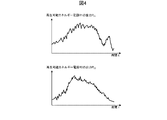
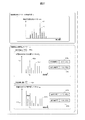
図22は、実施例2の周波数スペクトル演算結果データD28を示す。   FIG. 22 shows frequency spectrum calculation result data D28 of the second embodiment.

ここでの周波数スペクトル演算結果データD28は、制御期間に対して予測された、系統周波数変動スペクトルF(f)と、制御対象発電機G1の出力指令値スペクトルFM1(f)と、制御対象発電機G2の出力指令値スペクトルFM2(f)とを含む。ここで、制御対象発電機G1は、実施例1と同様、出力指令値時系列データPM1(t)に基づいて、逸脱発電機と判定されている。また、逸脱発電機G1の出力指令値スペクトルには、最大の周波数成分である影響量FM1dと、対応する影響周波数fs1とが示されている。 The frequency spectrum calculation result data D28 here is predicted for the control period, the system frequency fluctuation spectrum F f (f s ), the output command value spectrum F M1 (f s ) of the controlled generator G1, and control target generator output command value spectrum G2 F M2 containing (f s) and. Here, the controlled generator G1 is determined to be a deviation generator based on the output command value time-series data P M1 (t), as in the first embodiment. In addition, the output command value spectrum of the deviation generator G1 indicates the influence amount F M1d that is the maximum frequency component and the corresponding influence frequency f s1 .

逸脱量成分演算部22は、次の(5)式および(6)式を用いて、逸脱発電機G1の出力指令値スペクトルFM1の周波数成分のうち、影響量FM1dと、対応する影響周波数fs1の組を、逸脱量成分(FM1d、fs1)として演算する。 The deviation amount component calculation unit 22 uses the following equations (5) and (6), and among the frequency components of the output command value spectrum F M1 of the deviation generator G1, the influence amount F M1d and the corresponding influence frequency a set of f s1, departing weight component (F M1d, f s1) computed as.

Figure 0006367754
Figure 0006367754

Figure 0006367754
Figure 0006367754

このような逸脱量成分は、周波数スペクトルから簡単に求められる。これにより、系統運用者は逸脱量成分を理解しやすい。なお、逸脱量成分演算部22は、逸脱量成分としてこれ以外のものを演算し用いてもよい。また、再生可能エネルギー出力過去データや系統データや系統モデルデータによっては、逸脱量成分が存在しないケースも存在するため、このようなケースは逸脱量成分なしと判定され、ステップS1005に進む。以上がステップS1000の詳細である。   Such a deviation component is easily obtained from the frequency spectrum. Thereby, the system operator can easily understand the deviation component. The deviation amount component calculation unit 22 may calculate and use other deviation amount components. Also, depending on the past renewable energy output data, system data, and system model data, there may be cases where there is no deviation amount component, so such a case is determined to have no deviation amount component, and the process proceeds to step S1005. The above is the details of step S1000.

ステップS1100で余裕量成分演算部23は、時系列変化演算結果データD21と逸脱量成分演算結果データD22を用いて余裕量成分を演算し、余裕量成分演算結果データベース43に格納する。ここでは、ステップS1100の詳細について説明する。   In step S <b> 1100, the margin component calculation unit 23 calculates a margin component using the time-series change calculation result data D <b> 21 and the deviation component calculation result data D <b> 22 and stores the margin component in the margin component calculation result database 43. Here, details of step S1100 will be described.

図23は、実施例2の余裕量成分演算部23の処理を示す。   FIG. 23 illustrates the processing of the surplus amount component calculation unit 23 according to the second embodiment.

ステップS1101で余裕量成分演算部23は、時系列変化演算結果データD21を読み込み、制御対象発電機の中から逸脱発電機を除いて順に一つの制御対象発電機を出力調整対象候補発電機として選択し、出力調整対象候補発電機を示す情報をメモリ12に読み込む。ステップS1102で余裕量成分演算部23は、出力調整対象候補発電機を非逸脱発電機と設定し、設定内容を時系列変化演算結果データベース41に保存する。ステップS1103で余裕量成分演算部23は、逸脱量成分演算結果データベース42から逸脱量成分をメモリ12に読み込み、周波数スペクトル演算結果データベース48から、出力調整対象候補発電機の出力指令値スペクトルをメモリ12に読み込み、出力調整対象候補発電機の出力指令値スペクトルのうち影響周波数の周波数成分を対象量として演算し、対象量の逆数を余裕量として演算し、余裕量と影響周波数の組を余裕量成分として余裕量成分演算結果データベース43に格納する。ステップS1104で余裕量成分演算部23は、逸脱発電機を除く全ての出力調整対象候補発電機を選択したかを判定し、全ての出力調整対象候補発電機を選択していない場合には、ステップS1101に戻り、全ての出力調整対象候補発電機を選択した場合には、処理を終了する。   In step S1101, the surplus amount component calculation unit 23 reads the time-series change calculation result data D21, and sequentially selects one control target generator as an output adjustment target candidate generator from the control target generator except for the deviation generator. The information indicating the output adjustment target candidate generator is read into the memory 12. In step S <b> 1102, the margin component calculation unit 23 sets the output adjustment target candidate generator as a non-deviation generator, and stores the setting contents in the time-series change calculation result database 41. In step S1103, the margin component calculation unit 23 reads the deviation component from the deviation component calculation result database 42 into the memory 12, and stores the output command value spectrum of the output adjustment target candidate generator from the frequency spectrum calculation result database 48 in the memory 12. Of the output command value spectrum of the output adjustment target candidate generator, the frequency component of the influence frequency is calculated as the target amount, the reciprocal of the target amount is calculated as the margin amount, and the combination of the margin amount and the influence frequency is the margin amount component. Is stored in the margin component calculation result database 43 as follows. In step S1104, the margin component calculation unit 23 determines whether all output adjustment target candidate generators except for the deviation generator are selected, and if all output adjustment target candidate generators are not selected, the step is performed. Returning to S1101, if all output adjustment target candidate generators have been selected, the process ends.

前述の図22において、制御対象発電機G2は、非逸脱発電機と判定されている。   In FIG. 22 described above, the controlled generator G2 is determined to be a non-deviation generator.

余裕量成分演算部23は、非逸脱発電機G2の出力指令値スペクトルFM2と、影響周波数fs1と、次の(7)式とを用いて、影響周波数の周波数成分の大きさである対象量FM2(fs1)から、余裕量FM2mを算出し、余裕量と影響周波数の組を余裕量成分(FM2m、fs1)とする。 Allowance component calculation unit 23, an output command value spectrum F M2 non departing generator G2, and impact frequency f s1, using the following equation (7), the magnitude of the frequency components of the impact frequency subject A margin amount F M2m is calculated from the amount F M2 (f s1 ), and a set of the margin amount and the influence frequency is defined as a margin component (F M2m , f s1 ).

Figure 0006367754
Figure 0006367754

このような余裕量成分は、出力指令値スペクトルから簡単に求められる。これにより、系統運用者は余裕量成分を理解しやすい。なお、余裕量成分演算部23は、余裕量成分としてこれ以外のものを用いてもよい。以上がステップS1100の詳細である。   Such a margin component can be easily obtained from the output command value spectrum. As a result, the system operator can easily understand the surplus component. The margin component calculation unit 23 may use other components as the margin component. The above is the details of step S1100.

ステップS1200で出力調整量演算部24は、逸脱量成分演算結果データD22から、各逸脱発電機の逸脱量成分をメモリ12に読み込み、各逸脱発電機の逸脱量成分の影響量の和を、非逸脱発電機の出力調整量の合計である非逸脱発電機合計出力調整量として演算し、出力調整量演算結果データベース44に格納する。なお、出力調整量演算部24は、非逸脱発電機合計出力調整量としてこれ以外の値を用いても良い。   In step S1200, the output adjustment amount calculation unit 24 reads the departure amount component of each departure generator from the departure amount component calculation result data D22 into the memory 12, and calculates the sum of the influence amount of the departure amount component of each departure generator. It is calculated as a non-deviation generator total output adjustment amount, which is the total output adjustment amount of the deviation generator, and stored in the output adjustment amount calculation result database 44. The output adjustment amount calculation unit 24 may use a value other than this as the non-deviation generator total output adjustment amount.

ステップS1300で出力調整対象決定部25は、時系列変化演算結果データD21と逸脱量成分演算結果データD22と余裕量成分演算結果データD23と出力調整量演算結果データD24を用いて出力調整対象を決定し、出力調整対象決定結果データベース45に格納する。ここでは、ステップS1300の詳細について説明する。   In step S1300, the output adjustment target determination unit 25 determines the output adjustment target using the time series change calculation result data D21, the deviation component calculation result data D22, the margin component calculation result data D23, and the output adjustment amount calculation result data D24. And stored in the output adjustment target determination result database 45. Here, details of step S1300 will be described.

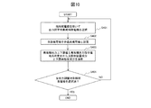
図24は、実施例2の出力調整対象決定部25の処理を示す。   FIG. 24 illustrates processing of the output adjustment target determination unit 25 according to the second embodiment.

ステップS1301で出力調整対象決定部25は、時系列変化演算結果データD21を読み込み、制御対象発電機の中から順に一つの制御対象発電機を出力調整対象候補発電機として選択し、出力調整対象候補発電機を示す情報をメモリ12に読み込む。ステップS1302では、出力調整対象発電機の種類を判定する。ここで、当該発電機の種類が逸脱発電機の場合はステップS1303に進む。一方、当該発電機の種類が非逸脱発電機の場合、出力調整対象決定部25はステップS1304に進む。ステップS1303で出力調整対象決定部25は、逸脱量成分演算結果データD22から当該逸脱発電機の逸脱量成分をメモリ12に読み込み、読み込んだ逸脱量成分の影響量FM1dの符号を反転させた値を当該逸脱発電機の出力調整量と設定し、設定内容を出力調整対象決定結果データベース45に格納する。ステップS1304で出力調整対象決定部25は、余裕量成分演算結果データD23と出力調整量演算結果データD24をメモリ12に読み込み、非逸脱発電機合計出力調整量を当該非逸脱発電機の余裕量の比に応じて按分する。ステップS1305で出力調整対象決定部25は、按分結果を当該非逸脱発電機の出力調整量として設定し、出力調整対象決定結果データベース45に格納する。ステップS1306で出力調整対象決定部25は、全ての出力調整対象候補発電機を選択したかを判定し、全ての出力調整対象候補発電機を選択していない場合には、ステップS1301に戻り、全ての出力調整対象候補発電機を選択した場合には、処理を終了する。以上がステップS1300の詳細である。 In step S1301, the output adjustment target determination unit 25 reads the time-series change calculation result data D21, and sequentially selects one control target generator from among the control target generators as an output adjustment target candidate generator. Information indicating the generator is read into the memory 12. In step S1302, the type of output adjustment target generator is determined. Here, if the type of the generator is a deviation generator, the process proceeds to step S1303. On the other hand, when the type of the generator is a non-deviation generator, the output adjustment target determination unit 25 proceeds to step S1304. In step S1303, the output adjustment target determination unit 25 reads the deviation component of the deviation generator from the deviation component calculation result data D22 into the memory 12, and the value obtained by inverting the sign of the read influence amount F M1d of the deviation component. Is set as the output adjustment amount of the deviation generator, and the setting contents are stored in the output adjustment target determination result database 45. In step S1304, the output adjustment target determining unit 25 reads the margin component calculation result data D23 and the output adjustment amount calculation result data D24 into the memory 12, and sets the non-deviation generator total output adjustment amount to the margin amount of the non-deviation generator. Prorate according to the ratio. In step S <b> 1305, the output adjustment target determination unit 25 sets the apportionment result as the output adjustment amount of the non-deviation generator and stores it in the output adjustment target determination result database 45. In step S1306, the output adjustment target determination unit 25 determines whether all output adjustment target candidate generators have been selected. If all output adjustment target candidate generators have not been selected, the process returns to step S1301, and all the output adjustment target candidate generators have been selected. When the output adjustment target candidate generator is selected, the process ends. The above is the details of step S1300.

なお、複数の逸脱発電機と、複数の影響周波数が検出された場合、負荷周波数制御装置10xは、影響周波数毎に、非逸脱発電機合計出力調整量と、非逸脱発電機の余裕量成分と、非逸脱発電機の出力調整量とを算出してもよい。   When a plurality of deviation generators and a plurality of influence frequencies are detected, the load frequency control device 10x, for each influence frequency, the non-deviation generator total output adjustment amount and the margin component of the non-deviation generator The output adjustment amount of the non-developed generator may be calculated.

なお、出力上下限値の代わりに、各周波数成分の上限値が予め設定されてもよい。この場合、負荷周波数制御装置10は、各周波数成分について上限値を逸脱するか否かを判定し、出力指令値スペクトルの各周波数成分と上限値の比較により、逸脱量成分および余裕量成分を算出する。   Instead of the output upper and lower limit values, the upper limit value of each frequency component may be set in advance. In this case, the load frequency control device 10 determines whether or not each frequency component deviates from the upper limit value, and calculates a deviation component and a margin component by comparing each frequency component of the output command value spectrum with the upper limit value. To do.

負荷周波数制御装置10xは、逸脱発電機の出力指令値スペクトルから逸脱に最も大きい影響を与える影響周波数の成分を除去し、逸脱量成分の大きさの和である非逸脱発電機合計出力調整量を、余裕量成分の大きさに応じて非逸脱発電機へ配分し、非逸脱発電機の影響周波数の成分に加えることにより、制御対象発電機の出力の合計に与える影響を抑えつつ、出力指令値及び系統周波数の逸脱を防ぐことができる。言い換えれば、負荷周波数制御装置10xは、全ての逸脱発電機の影響周波数の成分の出力調整量の合計を打ち消すように、全ての非逸脱発電機の影響周波数の成分の出力調整量の合計を決定する。   The load frequency control device 10x removes the influence frequency component that has the greatest influence on the deviation from the output command value spectrum of the deviation generator, and calculates the non-deviation generator total output adjustment amount that is the sum of the magnitudes of the deviation amount components. The output command value is controlled while allocating to the non-developed generator according to the size of the margin component and adding it to the influence frequency component of the non-developed generator, while suppressing the influence on the total output of the controlled generator. Moreover, deviation of the system frequency can be prevented. In other words, the load frequency control device 10x determines the sum of the output adjustment amounts of the influence frequency components of all the non-deviation generators so as to cancel the sum of the output adjustment amounts of the influence frequency components of all the deviation generators. To do.

ステップS1400で出力調整指令部26は、各逸脱発電機に対して、出力指令値スペクトルのうち影響周波数の成分の出力調整量を示す指令を送信する。   In step S1400, the output adjustment command unit 26 transmits a command indicating the output adjustment amount of the influence frequency component in the output command value spectrum to each deviation generator.

以上の処理によれば、負荷周波数制御装置10xは、逸脱発電機の逸脱量成分から逸脱発電機の出力調整量を容易に算出することができる。また、負荷周波数制御装置10は、逸脱発電機の逸脱量成分と非逸脱発電機の余裕量成分とに基づいて、非逸脱発電機の出力調整量を容易に算出することができる。これにより、負荷周波数制御装置10は、高速に出力調整量を算出することができ、より短い制御周期であっても、処理を完了することができる。   According to the above process, the load frequency control device 10x can easily calculate the output adjustment amount of the departure generator from the departure amount component of the departure generator. Further, the load frequency control device 10 can easily calculate the output adjustment amount of the non-deviation generator based on the deviation component of the deviation generator and the margin component of the non-deviation generator. Thereby, the load frequency control apparatus 10 can calculate the output adjustment amount at high speed, and can complete the processing even in a shorter control cycle.

図25は、実施例2の発電機情報画面を示す。   FIG. 25 shows a generator information screen of the second embodiment.

発電機情報画面は、逸脱情報410xと出力調整情報420xとを含む。   The generator information screen includes deviation information 410x and output adjustment information 420x.

逸脱情報410xは、出力調整前の状態を示す。逸脱情報410xは、系統周波数の上下限値逸脱の有無411と、逸脱発電機の選択を受け付ける選択欄412と、当該発電機の逸脱量成分413xと、当該発電機の逸脱時刻414と、当該発電機の位置を示す系統図415とを示す。   Deviation information 410x indicates a state before output adjustment. Deviation information 410x includes presence / absence 411 of system frequency upper / lower limit deviation, selection column 412 for accepting selection of a deviation generator, deviation amount component 413x of the generator, deviation time 414 of the generator, and power generation A system diagram 415 showing the position of the machine is shown.

出力調整情報420xは、出力調整後の状態を示す。出力調整情報420xは例えば、系統周波数の上下限値逸脱の有無421と、出力調整の対象である調整発電機の選択を受け付ける選択欄422と、当該発電機の出力調整量423xと、当該発電機の位置を示す系統図425とを示す。   The output adjustment information 420x indicates a state after output adjustment. The output adjustment information 420x includes, for example, presence / absence of a deviation 421 of the upper and lower limit values of the system frequency, a selection field 422 for receiving selection of an adjustment generator that is an object of output adjustment, an output adjustment amount 423x of the generator, and the generator The system diagram 425 which shows the position of is shown.

このような演算結果を、負荷周波数制御装置10xや、通信ネットワーク300を介して監視制御装置200の画面に表示することで、電力系統100において、どの発電機が、いつ、どの程度の逸脱量成分を持って逸脱するか、どの発電機をどの程度出力調整するかが一目でわかる。   By displaying such a calculation result on the screen of the monitoring control device 200 via the load frequency control device 10x or the communication network 300, which generator in the power system 100, when and how much deviation component. It is easy to tell at a glance whether the generator deviates with the power level and which generator adjusts the output.

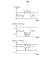
図26は、実施例2の時系列データ画面を示す。   FIG. 26 shows a time-series data screen of the second embodiment.

時系列データ画面は、出力調整前の時系列データと、出力調整後の時系列データとを示す。時系列データ画面は例えば、出力調整前の系統周波数変動時系列データ431(破線)と、出力調整後の系統周波数変動時系列データ441(実線)と、制御対象発電機の選択を受け付ける選択欄432aと、出力調整前の当該発電機の出力指令値時系列データ433a(破線)と、当該発電機が逸脱発電機である場合の逸脱量成分434axと、当該発電機の逸脱時刻437aと、当該発電機の出力調整量436axと、出力調整後の当該発電機の出力指令値時系列データ443a(実線)と、別の制御対象発電機の選択を受け付ける選択欄432bと、出力調整前の当該発電機の出力指令値時系列データ433b(破線)と、当該発電機が非逸脱発電機である場合の余裕量成分435bxと、当該発電機の出力調整量436bxと、出力調整後の当該発電機の出力指令値時系列データ443b(実線)とを示す。   The time series data screen shows time series data before output adjustment and time series data after output adjustment. The time series data screen includes, for example, system frequency fluctuation time series data 431 (broken line) before output adjustment, system frequency fluctuation time series data 441 (solid line) after output adjustment, and a selection field 432a for receiving selection of a control generator. Output command value time-series data 433a (broken line) of the generator before output adjustment, a deviation component 434ax when the generator is a deviation generator, a deviation time 437a of the generator, and the power generation Output adjustment amount 436ax of the machine, output command value time series data 443a (solid line) of the generator after output adjustment, a selection field 432b for receiving selection of another generator to be controlled, and the generator before output adjustment Output command value time-series data 433b (dashed line), margin component 435bx when the generator is a non-developed generator, output adjustment amount 436bx of the generator, and output Output command value of the generator Retighten time showing the sequence data 443b (solid line).

時系列情報画面のような演算結果を、負荷周波数制御装置10や、通信ネットワーク300を介して監視制御装置200の画面に表示することで、電力系統100の逸脱発電機および非逸脱発電機の出力指令値時系列データが、どのように出力調整されたかが一目でわかる。また、逸脱発電機、または、非逸脱発電機が複数存在する場合、系統運用者は、発電機を選択し、選択した発電機の時系列変化演算結果と逸脱量成分演算結果と余裕量成分演算結果と出力調整対象決定結果を確認することができる。   The calculation results such as the time series information screen are displayed on the screen of the monitoring control device 200 via the load frequency control device 10 or the communication network 300, so that the outputs of the deviation generator and the non-deviation generator of the power system 100 are output. You can see at a glance how the output of the command value time-series data is adjusted. In addition, when there are multiple deviation generators or non-deviation generators, the grid operator selects a generator and calculates the time series change calculation result, deviation component calculation result, and margin component calculation of the selected generator. The result and the output adjustment target determination result can be confirmed.

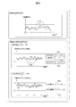
図27は、実施例2の周波数スペクトル画面を示す。   FIG. 27 shows a frequency spectrum screen of the second embodiment.

周波数スペクトル画面は、出力調整前の周波数スペクトルと、出力調整後の周波数スペクトルとを示す。周波数スペクトル画面は例えば、出力調整前の系統周波数変動スペクトル451(破線)と、出力調整後の系統周波数変動スペクトル461(実線)と、制御対象発電機の選択を受け付ける選択欄432aと、出力調整前の当該発電機の出力指令値スペクトル453a(破線)と、当該発電機が逸脱発電機である場合の逸脱量成分454aと、当該発電機の出力調整量456aと、出力調整後の当該発電機の出力指令値スペクトル463a(実線)と、別の制御対象発電機の選択を受け付ける選択欄432bと、出力調整前の当該発電機の出力指令値スペクトル453b(破線)と、当該発電機が非逸脱発電機である場合の余裕量成分455bと、当該発電機の出力調整量456bと、出力調整後の当該発電機の出力指令値スペクトル463b(実線)とを示す。   The frequency spectrum screen shows a frequency spectrum before output adjustment and a frequency spectrum after output adjustment. The frequency spectrum screen includes, for example, a system frequency fluctuation spectrum 451 (dashed line) before output adjustment, a system frequency fluctuation spectrum 461 (solid line) after output adjustment, a selection field 432a for receiving selection of a control target generator, and before output adjustment The output command value spectrum 453a (broken line) of the generator, the deviation component 454a when the generator is a deviation generator, the output adjustment amount 456a of the generator, and the generator after the output adjustment Output command value spectrum 463a (solid line), selection field 432b for receiving selection of another generator to be controlled, output command value spectrum 453b (dashed line) of the generator before output adjustment, and the generator generates non-deviation power Margin component 455b in the case of a generator, output adjustment amount 456b of the generator, and output command value spectrum 463 of the generator after output adjustment (Solid line) showing the.

周波数スペクトル画面のような演算結果を、負荷周波数制御装置10や、通信ネットワーク300を介して監視制御装置200の画面に表示することで、逸脱発電機および非逸脱発電機の出力指令値スペクトルが、どのように調整されたかが一目でわかる。また、逸脱発電機、または、非逸脱発電機が複数存在する場合、系統運用者は、発電機を選択し、選択した発電機の時系列変化演算結果と逸脱量成分演算結果と余裕量成分演算結果と出力調整対象決定結果を確認することができる。   By displaying the calculation result such as the frequency spectrum screen on the screen of the monitoring control device 200 via the load frequency control device 10 or the communication network 300, the output command value spectra of the deviation generator and the non-deviation generator are You can see at a glance how it was adjusted. In addition, when there are multiple deviation generators or non-deviation generators, the grid operator selects a generator and calculates the time series change calculation result, deviation component calculation result, and margin component calculation of the selected generator. The result and the output adjustment target determination result can be confirmed.

以上の各実施例の処理において、ステップの順序を交換できる場合がある。例えば、S400とS500や、S1100とS1200は、交換されてもよい。   In the processes of the above embodiments, the order of steps may be exchanged. For example, S400 and S500 or S1100 and S1200 may be exchanged.

以上の各実施例によれば、負荷周波数制御装置は、逸脱発電機の逸脱量成分を抑圧し、且つ複数の制御対象発電機の出力の合計を維持することを調整条件に、各制御対象発電機の出力調整量を算出することにより、系統周波数の逸脱を防ぎつつ、需給バランスを維持することができる。また、負荷周波数制御装置は、出力上下限値を記憶し、出力指令値時系列データを予測することにより、容易に出力調整量を算出することができる。また、負荷周波数制御装置は、複数の制御対象発電機を逸脱発電機と非逸脱発電機に分け、逸脱発電機の逸脱量成分と、非逸脱発電機の余裕量成分と算出することにより、容易に調整条件を満たす調整量を算出することができる。また、負荷周波数制御装置が演算結果を表示装置に表示させることにより、系統運用者は、出力調整前及び出力調整の少なくとも何れかの情報を知ることができる。また、負荷周波数制御装置が系統周波数の変動の情報を表示装置に表示させることにより、系統運用者は、出力調整が必要となる系統周波数の変動を知ることができる。また、負荷周波数制御装置が出力調整量に基づく指令を、制御対象発電機へ送信し、制御対象発電機の出力を調整することにより、予測された系統周波数の逸脱を防ぐことができる。   According to each of the above embodiments, the load frequency control device suppresses the deviation amount component of the deviation generator and maintains the sum of the outputs of the plurality of control object generators under the adjustment condition. By calculating the output adjustment amount of the machine, it is possible to maintain a supply-demand balance while preventing deviations in the system frequency. Further, the load frequency control device can easily calculate the output adjustment amount by storing the output upper and lower limit values and predicting the output command value time-series data. In addition, the load frequency control device easily divides a plurality of controlled generators into deviation generators and non-deviation generators, and calculates the deviation component of the deviation generator and the margin component of the non-deviation generator. The adjustment amount that satisfies the adjustment condition can be calculated. Further, the load frequency control device displays the calculation result on the display device, so that the system operator can know at least one of the information before the output adjustment and the output adjustment. Further, the load frequency control device displays information on the fluctuation of the system frequency on the display device, so that the system operator can know the fluctuation of the system frequency that requires output adjustment. Further, the load frequency control device transmits a command based on the output adjustment amount to the controlled generator and adjusts the output of the controlled generator, thereby preventing the deviation of the predicted system frequency.

以上、本発明の実施形態を説明したが、これは本発明の説明のための例示であって、本発明の範囲を上記構成に限定する趣旨ではない。本発明は、他の種々の形態でも実施する事が可能である。   As mentioned above, although embodiment of this invention was described, this is an illustration for description of this invention, Comprising: It is not the meaning which limits the scope of the present invention to the said structure. The present invention can be implemented in various other forms.

10、10x:負荷周波数制御装置、 11:CPU、 12:メモリ、 13:入力部、 14:通信部、 15:表示部、 20、20x:負荷周波数制御量演算部、 21:時系列変化演算部、 22:逸脱量成分演算部、 23:余裕量成分演算部、 24:出力調整量演算部、 25:出力調整対象決定部、 26:出力調整指令部、 27:表示部、 28:周波数スペクトル演算部、 29:状態推定演算部、 30、30x:負荷周波数制御量演算入力データベース、 40、40x:負荷周波数制御量演算結果データベース、 100:電力系統、 110A、110B:発電機、 120A、120B、120C、120D:ノード、 130A、130B:変圧器、 140A、140B、140C、140D:ブランチ、 150:計測装置、 200:監視制御装置、 300:通信ネットワーク   10, 10x: Load frequency control device, 11: CPU, 12: Memory, 13: Input unit, 14: Communication unit, 15: Display unit, 20, 20x: Load frequency control amount calculation unit, 21: Time series change calculation unit 22: Deviation amount component calculation unit 23: Margin amount component calculation unit 24: Output adjustment amount calculation unit 25: Output adjustment target determination unit 26: Output adjustment command unit 27: Display unit 28: Frequency spectrum calculation Unit, 29: state estimation calculation unit, 30, 30x: load frequency control amount calculation input database, 40, 40x: load frequency control amount calculation result database, 100: power system, 110A, 110B: generator, 120A, 120B, 120C , 120D: node, 130A, 130B: transformer, 140A, 140B, 140C, 140D: branch, 150: Measuring device 200: Monitoring and control device 300: Communication network

Claims (13)

記憶デバイスと、
前記記憶デバイスに接続された演算デバイスと、
を備え、
前記記憶デバイスは、再生可能エネルギー発電機及び複数の電源を含む電力系統に対し、前記電力系統のモデルを示す系統モデルデータと、前記電力系統の状態を示す系統データと、過去の前記再生可能エネルギー発電機の出力を示す再生可能エネルギーデータと、各電源の制約を示す電源データとを記憶し、
前記演算デバイスは、
前記系統モデルデータと前記系統データと前記再生可能エネルギーデータとに基づいて、未来の制御期間における各電源の状態を示す時系列データを予測し、
前記電源データに基づいて、各電源に対し、前記制約に対する前記時系列データの逸脱の程度を示す逸脱状態と、前記制約に対する前記時系列データの余裕の程度を示す余裕状態との少なくとも何れか一つを算出し、
前記逸脱状態を解消し、且つ前記複数の電源の出力の合計を維持することを条件として、前記逸脱状態及び前記余裕状態に基づいて、各電源の出力の調整量を算出する、
負荷周波数制御装置。
A storage device;
A computing device connected to the storage device;
With
The storage device includes, for a power system including a renewable energy generator and a plurality of power sources, system model data indicating a model of the power system, system data indicating a state of the power system, and the past renewable energy Renewable energy data indicating the output of the generator and power supply data indicating the constraints of each power supply are stored,
The computing device is
Based on the system model data, the system data and the renewable energy data, predict time series data indicating the state of each power supply in a future control period,
Based on the power supply data, for each power supply, at least one of a deviation state indicating a degree of deviation of the time series data with respect to the restriction and a margin state indicating a degree of margin of the time series data with respect to the restriction. Calculate
Calculate the adjustment amount of the output of each power supply based on the departure state and the margin state, on condition that the departure state is eliminated and the total of the outputs of the plurality of power supplies is maintained.
Load frequency control device.
前記時系列データは、対応する電源の出力指令値を示し、
前記制約は、対応する電源の出力指令値の範囲を示す、
請求項1に記載の負荷周波数制御装置。
The time series data indicates the output command value of the corresponding power supply,
The constraint indicates the range of the output command value of the corresponding power supply,
The load frequency control device according to claim 1.
前記演算デバイスは、各電源に対し、前記時系列データが前記範囲を逸脱するか否かを判定し、
前記演算デバイスは、前記複数の電源のうち、前記時系列データが前記範囲を逸脱すると判定された電源である逸脱電源の逸脱状態を算出し、
前記演算デバイスは、前記複数の電源のうち、前記時系列データが前記範囲を逸脱しないと判定された電源である非逸脱電源の余裕状態を算出する、
請求項2に記載の負荷周波数制御装置。
The computing device determines, for each power supply, whether the time series data deviates from the range,
The computing device calculates a deviation state of a deviation power source that is a power source determined to deviate the time series data from the range among the plurality of power sources,
The computing device calculates a marginal state of a non-deviation power source that is a power source determined that the time series data does not deviate from the range among the plurality of power sources.
The load frequency control device according to claim 2.
前記演算デバイスは、前記逸脱電源に対し、前記範囲の境界値と前記時系列データとの間の距離に基づいて、前記時系列データの逸脱量を、前記逸脱状態として算出し、
前記演算デバイスは、前記非逸脱電源に対し、前記範囲の境界値と前記時系列データとの間の距離に基づいて、前記時系列データの余裕量を、前記余裕状態として算出する、
請求項3に記載の負荷周波数制御装置。
The computing device calculates the deviation amount of the time series data as the deviation state based on the distance between the boundary value of the range and the time series data with respect to the deviation power source,
The computing device calculates the margin of the time series data as the margin state based on the distance between the boundary value of the range and the time series data for the non-deviation power source.
The load frequency control device according to claim 3.
前記演算デバイスは、前記逸脱電源に対し、前記逸脱の方向を示す符号を有する前記逸脱量を算出し、前記逸脱量の符号を反転することで、前記出力指令値の調整量を算出し、
前記演算デバイスは、全ての逸脱電源の逸脱量の合計を前記偏差として算出し、前記偏差を前記非逸脱電源の余裕量に応じて前記非逸脱電源に配分することで、前記非逸脱電源の出力指令値の調整量を算出する、
請求項4に記載の負荷周波数制御装置。
The arithmetic device calculates the deviation amount having a sign indicating the direction of deviation with respect to the deviation power source, and calculates the adjustment amount of the output command value by inverting the sign of the deviation amount,
The computing device calculates a sum of deviation amounts of all the deviation power sources as the deviation, and distributes the deviation to the non-deviation power source according to a margin amount of the non-deviation power source. Calculate the adjustment amount of the command value,
The load frequency control device according to claim 4.
前記演算デバイスは、前記逸脱電源に対し、前記時系列データのうち前記範囲から最も逸脱する時刻のデータを特定値として選択し、前記特定値から前記範囲の逸脱側の境界値を減じた値を前記逸脱量として算出し、
前記演算デバイスは、前記偏差が正値である場合、前記非逸脱電源に対し、前記範囲の上限値から前記時系列データの最大値を減じた値を、前記余裕量として用い、
前記演算デバイスは、前記偏差が負値である場合、前記非逸脱電源に対し、前記時系列データの最小値から前記範囲の下限値を減じた値を、前記余裕量として用いる、
請求項5に記載の負荷周波数制御装置。
The arithmetic device selects, as the specific value, data at a time most deviating from the range among the time series data for the deviating power source, and a value obtained by subtracting a boundary value on the deviating side of the range from the specific value. Calculated as the deviation amount,
When the deviation is a positive value, the arithmetic device uses, as the margin, a value obtained by subtracting the maximum value of the time series data from the upper limit value of the range for the non-deviation power source,
When the deviation is a negative value, the arithmetic device uses, as the margin, a value obtained by subtracting the lower limit value of the range from the minimum value of the time-series data for the non-deviation power source.
The load frequency control device according to claim 5.
前記演算デバイスは、各電源に対し、前記時系列データの周波数スペクトルを算出し、
前記演算デバイスは、前記逸脱電源に対し、前記周波数スペクトルの周波数成分の最大値である影響量を、前記逸脱状態として検出し、前記影響量の周波数を影響周波数として検出し、
前記演算デバイスは、前記非逸脱電源に対し、前記周波数スペクトルから、前記影響周波数の周波数成分を対象量として検出し、対象量の増大に対して減少する余裕量を、前記余裕状態として算出する、
請求項3に記載の負荷周波数制御装置。
The computing device calculates a frequency spectrum of the time series data for each power source,
The arithmetic device detects an influence amount that is a maximum value of a frequency component of the frequency spectrum as the deviation state with respect to the deviation power source, and detects a frequency of the influence amount as an influence frequency.
The arithmetic device detects the frequency component of the influence frequency as a target amount from the frequency spectrum for the non-deviation power source, and calculates a margin amount that decreases with an increase in the target amount as the margin state.
The load frequency control device according to claim 3.
前記演算デバイスは、前記逸脱電源の前記影響周波数の影響量を抑圧することを条件に前記逸脱電源の周波数スペクトルにおける前記影響周波数の成分の調整量を算出し、
前記演算デバイスは、全ての逸脱電源の前記影響周波数の影響量の合計を前記偏差として算出し、前記偏差を前記非逸脱電源の余裕量に応じて前記非逸脱電源に配分することで、前記非逸脱電源の周波数スペクトルにおける前記影響周波数の成分の調整量を算出する、
請求項7に記載の負荷周波数制御装置。
The arithmetic device calculates an adjustment amount of the influence frequency component in the frequency spectrum of the departure power source on condition that the influence amount of the influence frequency of the departure power source is suppressed,
The computing device calculates a sum of the influence amounts of the influence frequencies of all the deviation power sources as the deviation, and distributes the deviation to the non-deviation power source according to a margin of the non-deviation power source. Calculating an adjustment amount of the component of the influence frequency in the frequency spectrum of the deviation power source;
The load frequency control device according to claim 7.
前記演算デバイスは、前記非逸脱電源に対し、前記対象量の逆数を前記余裕量として算出する、
請求項8に記載の負荷周波数制御装置。
The computing device calculates the reciprocal of the target amount as the margin for the non-deviation power source,
The load frequency control device according to claim 8.
前記演算デバイスは、前記複数の電源の中の特定電源について、前記時系列データと、前記逸脱状態と、前記余裕状態と、前記調整量との少なくとも何れか一つを、表示装置に表示させる、
請求項1乃至9の何れか一項に記載の負荷周波数制御装置。
The arithmetic device causes a display device to display at least one of the time series data, the deviation state, the margin state, and the adjustment amount for a specific power source among the plurality of power sources.
The load frequency control apparatus as described in any one of Claims 1 thru | or 9.
前記記憶デバイスは、前記電力系統の系統周波数の制約を記憶し、
前記演算デバイスは、前記系統モデルデータと前記系統データと前記再生可能エネルギーデータとに基づいて、前記制御期間における前記系統周波数の変動の時系列データを予測し、前記系統周波数の変動の時系列データと、前記系統周波数の制約に対する前記系統周波数の変動の時系列データの逸脱の有無との少なくとも何れか一つを、前記表示装置に表示させる、
請求項10に記載の負荷周波数制御装置。
The storage device stores system frequency constraints of the power system,
The arithmetic device predicts time-series data of fluctuations of the system frequency in the control period based on the system model data, the system data, and the renewable energy data, and time-series data of the system frequency fluctuations And at least one of the presence or absence of deviation of the time series data of the fluctuation of the system frequency with respect to the restriction of the system frequency is displayed on the display device,
The load frequency control device according to claim 10.
前記演算デバイスは、各電源に対し、前記調整量に基づく指令を送信する、
請求項1乃至9の何れか一項に記載の負荷周波数制御装置。
The arithmetic device transmits a command based on the adjustment amount to each power source.
The load frequency control apparatus as described in any one of Claims 1 thru | or 9.
再生可能エネルギー発電機及び複数の電源を含む電力系統に対し、前記電力系統のモデルを示す系統モデルデータと、前記電力系統の状態を示す系統データと、過去の前記再生可能エネルギー発電機の出力を示す再生可能エネルギーデータとに基づいて、未来の制御期間における各電源の出力の時系列データである時系列データを予測し、
各電源の制約を示す電源データに基づいて、各電源に対し、前記制約に対する前記時系列データの逸脱の程度を示す逸脱状態と、前記制約に対する前記時系列データの余裕の程度を示す余裕状態との少なくとも何れか一つを算出し、
前記逸脱状態を解消し、且つ前記複数の電源の出力の合計を維持することを条件として、前記逸脱状態及び前記余裕状態に基づいて、各電源の出力の調整量を算出する、
負荷周波数制御方法。
For a power system including a renewable energy generator and a plurality of power sources, system model data indicating a model of the power system, system data indicating a state of the power system, and output of the past renewable energy generator Based on the renewable energy data shown, predict the time series data that is the time series data of the output of each power supply in the future control period,
Based on the power supply data indicating the restrictions of each power supply, for each power supply, a deviation state indicating the degree of deviation of the time series data with respect to the restriction, and a margin state indicating the degree of margin of the time series data with respect to the restriction, Calculate at least one of
Calculate the adjustment amount of the output of each power supply based on the departure state and the margin state, on condition that the departure state is eliminated and the total of the outputs of the plurality of power supplies is maintained.
Load frequency control method.
JP2015098566A 2015-05-13 2015-05-13 Load frequency control device and load frequency control method Active JP6367754B2 (en)

Priority Applications (6)

Application Number Priority Date Filing Date Title
JP2015098566A JP6367754B2 (en) 2015-05-13 2015-05-13 Load frequency control device and load frequency control method
PCT/JP2016/062049 WO2016181754A1 (en) 2015-05-13 2016-04-15 Device for controlling load frequency and method for controlling load frequency
PL16792479.4T PL3297113T3 (en) 2015-05-13 2016-04-15 Device for controlling load frequency and method for controlling load frequency
ES16792479T ES2928572T3 (en) 2015-05-13 2016-04-15 Device for controlling the charging frequency and method for controlling the charging frequency
EP16792479.4A EP3297113B1 (en) 2015-05-13 2016-04-15 Device for controlling load frequency and method for controlling load frequency
US15/571,172 US10389133B2 (en) 2015-05-13 2016-04-15 Device and method for controlling power system

Applications Claiming Priority (1)

Application Number Priority Date Filing Date Title
JP2015098566A JP6367754B2 (en) 2015-05-13 2015-05-13 Load frequency control device and load frequency control method

Publications (2)

Publication Number Publication Date
JP2016214045A JP2016214045A (en) 2016-12-15
JP6367754B2 true JP6367754B2 (en) 2018-08-01

Family

ID=57247921

Family Applications (1)

Application Number Title Priority Date Filing Date
JP2015098566A Active JP6367754B2 (en) 2015-05-13 2015-05-13 Load frequency control device and load frequency control method

Country Status (6)

Country Link
US (1) US10389133B2 (en)
EP (1) EP3297113B1 (en)
JP (1) JP6367754B2 (en)
ES (1) ES2928572T3 (en)
PL (1) PL3297113T3 (en)
WO (1) WO2016181754A1 (en)

Families Citing this family (12)

* Cited by examiner, † Cited by third party
Publication number Priority date Publication date Assignee Title
JP6367754B2 (en) * 2015-05-13 2018-08-01 株式会社日立製作所 Load frequency control device and load frequency control method
US20180225779A1 (en) * 2017-02-07 2018-08-09 Foresight Energy Ltd System and method for determining power production in an electrical power grid
US20210334914A1 (en) * 2017-02-07 2021-10-28 Foresight Energy Ltd System and method for determining power production in an electrical power grid
CN106992544B (en) * 2017-05-02 2019-10-11 深圳市矩形科技有限公司 Microgrid energy real-time management control method
US10892638B2 (en) * 2017-08-03 2021-01-12 Heila Technologies, Inc. Automatic detection of distributed energy resources system parameters
EP3662421A4 (en) 2017-08-03 2021-01-20 Heila Technologies, Inc. Grid asset manager
WO2020102450A1 (en) 2018-11-13 2020-05-22 Heila Technologies, Inc. Decentralized hardware-in-the loop scheme
JP7206874B2 (en) * 2018-12-10 2023-01-18 富士電機株式会社 Control device, control method and program
EP3751699B1 (en) * 2019-06-13 2021-09-15 Siemens Aktiengesellschaft Method and apparatus for estimating a condition of an energy distribution network
CN110297145B (en) * 2019-07-29 2021-03-02 广东电网有限责任公司 Voltage sag detection method based on multi-user electric energy data deep analysis
CN111224434B (en) * 2020-03-12 2021-08-06 安徽工程大学 Load frequency coordination optimization control method of light-fire storage hybrid power generation system
US20230344241A1 (en) * 2022-04-22 2023-10-26 Aclara Technologies Llc System and method of linear state estimation of a distribution network from synchronous smart meter and line sensor

Family Cites Families (14)

* Cited by examiner, † Cited by third party
Publication number Priority date Publication date Assignee Title
JP3316771B2 (en) 1993-03-26 2002-08-19 株式会社日立製作所 Power system voltage control method and device
JP2007009804A (en) * 2005-06-30 2007-01-18 Tohoku Electric Power Co Inc Schedule system for output-power control of wind power-plant
JP4551921B2 (en) * 2007-09-27 2010-09-29 株式会社日立エンジニアリング・アンド・サービス Wind power generation system with storage system
JP5526079B2 (en) * 2011-05-30 2014-06-18 株式会社日立パワーソリューションズ Wind power generation system and method for adding wind power generator in wind power generation system
US9020800B2 (en) 2011-06-20 2015-04-28 The Aes Corporation Method and apparatus for controlling energy services based on market data
JP2013126260A (en) * 2011-12-13 2013-06-24 Hokkaido Electric Power Co Inc:The Operation apparatus and method of natural variation power supply
JP5957235B2 (en) * 2012-01-30 2016-07-27 株式会社東芝 Operation planning system
JP5797599B2 (en) * 2012-04-19 2015-10-21 株式会社日立パワーソリューションズ Power generation amount prediction method and system
CN104969436B (en) * 2013-02-07 2018-05-22 维斯塔斯风力系统集团公司 For providing the power plant of power grid assistant service and energy storage system
JP5465816B1 (en) * 2013-07-04 2014-04-09 中国電力株式会社 Frequency control system and frequency control method
US8963353B1 (en) 2013-09-19 2015-02-24 General Electric Company System and method to minimize grid spinning reserve losses by pre-emptively sequencing power generation equipment to offset wind generation capacity based on geospatial regional wind conditions
JP6397760B2 (en) * 2014-12-26 2018-09-26 株式会社日立製作所 Power system stabilization apparatus and method
JP6412822B2 (en) * 2015-04-22 2018-10-24 株式会社日立製作所 Power system voltage reactive power monitoring and control apparatus and method
JP6367754B2 (en) * 2015-05-13 2018-08-01 株式会社日立製作所 Load frequency control device and load frequency control method

Also Published As

Publication number Publication date
US20180262010A1 (en) 2018-09-13
EP3297113B1 (en) 2022-10-12
ES2928572T3 (en) 2022-11-21
EP3297113A4 (en) 2018-10-31
WO2016181754A1 (en) 2016-11-17
US10389133B2 (en) 2019-08-20
EP3297113A1 (en) 2018-03-21
PL3297113T3 (en) 2022-11-21
JP2016214045A (en) 2016-12-15

Similar Documents

Publication Publication Date Title
JP6367754B2 (en) Load frequency control device and load frequency control method
EP3392995B1 (en) Voltage stability monitoring device and method
Capitanescu et al. Unified sensitivity analysis of unstable or low voltages caused by load increases or contingencies
JP5811302B2 (en) Control device, power storage device, battery control system, battery control device, control method, battery control method, and recording medium
JP6427090B2 (en) Power generation amount prediction device, power generation amount prediction method, system stabilization device, and system stabilization method
US10461538B2 (en) System stabilization control device and power system control system
Geng et al. A hybrid dynamic optimization approach for stability constrained optimal power flow
US20170146574A1 (en) Voltage stability monitoring device and method
JP6319289B2 (en) Supply and demand adjustment system, supply and demand adjustment method, and supply and demand adjustment program
JP6530172B2 (en) POWER SYSTEM MONITORING DEVICE AND POWER SYSTEM MONITORING METHOD
EP3609033B1 (en) Power system stabilization device and power system stabilization method
Sajadi et al. Small-signal stability analysis of large-scale power systems in response to variability of offshore wind power plants
Naidji et al. Efficient allocation strategy of energy storage systems in power grids considering contingencies
JP2018057117A (en) Electric power system stabilizer and method
EP3104487A1 (en) Energy management system
JP2016042748A (en) Energy management system and power demand plan optimization method
Guerra Sánchez et al. A review of tools, models and techniques for long-term assessment of distribution systems using OpenDSS and parallel computing
US20160092776A1 (en) Optimizing sizing of grid-scale batteries for frequency regulation services
JP2019193387A (en) Power system monitoring device and power system monitoring method
RU2611259C1 (en) Automated device for determining limit modes of electrical systems
Zhang et al. Optimal Sizing and Siting of BESS in High Wind Penetrated Power Systems: A Strategy Considering Frequency and Voltage Control
Peppanen et al. Impact and Value of Energy Storage on a High-DER Penetration Distribution Feeder in Southern California
Zhou Online voltage stability prediction and control using computational intelligence technique
US20240160803A1 (en) Co-simulation of steady state and transient behaviors of an electric system
Subramanian et al. Loss Minimization and Voltage Profile Improvement Incorporating Multiple SVC using PSO Algorithm

Legal Events

Date Code Title Description
A621 Written request for application examination

Free format text: JAPANESE INTERMEDIATE CODE: A621

Effective date: 20180117

TRDD Decision of grant or rejection written
A01 Written decision to grant a patent or to grant a registration (utility model)

Free format text: JAPANESE INTERMEDIATE CODE: A01

Effective date: 20180612

A61 First payment of annual fees (during grant procedure)

Free format text: JAPANESE INTERMEDIATE CODE: A61

Effective date: 20180705

R150 Certificate of patent or registration of utility model

Ref document number: 6367754

Country of ref document: JP

Free format text: JAPANESE INTERMEDIATE CODE: R150