JP6362793B2 - Display management for high dynamic range video - Google Patents
Display management for high dynamic range video Download PDFInfo
- Publication number
- JP6362793B2 JP6362793B2 JP2017549366A JP2017549366A JP6362793B2 JP 6362793 B2 JP6362793 B2 JP 6362793B2 JP 2017549366 A JP2017549366 A JP 2017549366A JP 2017549366 A JP2017549366 A JP 2017549366A JP 6362793 B2 JP6362793 B2 JP 6362793B2
- Authority
- JP
- Japan
- Prior art keywords
- tone
- output image
- image
- pixel value
- color
- Prior art date
- Legal status (The legal status is an assumption and is not a legal conclusion. Google has not performed a legal analysis and makes no representation as to the accuracy of the status listed.)
- Active
Links
- 238000013507 mapping Methods 0.000 claims description 65
- 238000000034 method Methods 0.000 claims description 43
- 238000006243 chemical reaction Methods 0.000 claims description 17
- 229920006395 saturated elastomer Polymers 0.000 claims description 6
- 230000008859 change Effects 0.000 claims description 3
- 238000003708 edge detection Methods 0.000 claims description 3
- 238000004321 preservation Methods 0.000 claims description 3
- 230000006870 function Effects 0.000 description 22
- 238000007726 management method Methods 0.000 description 17
- 235000019557 luminance Nutrition 0.000 description 14
- 230000008569 process Effects 0.000 description 14
- 238000012545 processing Methods 0.000 description 12
- 230000000007 visual effect Effects 0.000 description 10
- 230000003044 adaptive effect Effects 0.000 description 7
- 238000013139 quantization Methods 0.000 description 5
- 230000009466 transformation Effects 0.000 description 5
- 230000008901 benefit Effects 0.000 description 4
- 239000003086 colorant Substances 0.000 description 4
- 238000004364 calculation method Methods 0.000 description 3
- 238000013500 data storage Methods 0.000 description 3
- 238000004519 manufacturing process Methods 0.000 description 3
- 239000011159 matrix material Substances 0.000 description 3
- 230000035945 sensitivity Effects 0.000 description 3
- 238000012546 transfer Methods 0.000 description 3
- 238000013459 approach Methods 0.000 description 2
- 238000012937 correction Methods 0.000 description 2
- 230000000694 effects Effects 0.000 description 2
- 230000004044 response Effects 0.000 description 2
- 241000023320 Luma <angiosperm> Species 0.000 description 1
- 230000006978 adaptation Effects 0.000 description 1
- 238000003491 array Methods 0.000 description 1
- 238000013501 data transformation Methods 0.000 description 1
- 230000003247 decreasing effect Effects 0.000 description 1
- 238000011161 development Methods 0.000 description 1
- 238000003384 imaging method Methods 0.000 description 1
- 238000012886 linear function Methods 0.000 description 1
- OSWPMRLSEDHDFF-UHFFFAOYSA-N methyl salicylate Chemical compound COC(=O)C1=CC=CC=C1O OSWPMRLSEDHDFF-UHFFFAOYSA-N 0.000 description 1
- 238000010606 normalization Methods 0.000 description 1
- 230000003287 optical effect Effects 0.000 description 1
- 238000012805 post-processing Methods 0.000 description 1
- 238000007781 pre-processing Methods 0.000 description 1
- 238000012360 testing method Methods 0.000 description 1
- 238000000844 transformation Methods 0.000 description 1
Images


Classifications
-
- H—ELECTRICITY
- H04—ELECTRIC COMMUNICATION TECHNIQUE
- H04N—PICTORIAL COMMUNICATION, e.g. TELEVISION
- H04N1/00—Scanning, transmission or reproduction of documents or the like, e.g. facsimile transmission; Details thereof
- H04N1/46—Colour picture communication systems
- H04N1/56—Processing of colour picture signals
- H04N1/60—Colour correction or control
- H04N1/6058—Reduction of colour to a range of reproducible colours, e.g. to ink- reproducible colour gamut
-
- G—PHYSICS
- G06—COMPUTING; CALCULATING OR COUNTING
- G06T—IMAGE DATA PROCESSING OR GENERATION, IN GENERAL
- G06T5/00—Image enhancement or restoration
-
- G—PHYSICS
- G06—COMPUTING; CALCULATING OR COUNTING
- G06T—IMAGE DATA PROCESSING OR GENERATION, IN GENERAL
- G06T7/00—Image analysis
- G06T7/90—Determination of colour characteristics
-
- G—PHYSICS
- G09—EDUCATION; CRYPTOGRAPHY; DISPLAY; ADVERTISING; SEALS
- G09G—ARRANGEMENTS OR CIRCUITS FOR CONTROL OF INDICATING DEVICES USING STATIC MEANS TO PRESENT VARIABLE INFORMATION
- G09G5/00—Control arrangements or circuits for visual indicators common to cathode-ray tube indicators and other visual indicators
- G09G5/02—Control arrangements or circuits for visual indicators common to cathode-ray tube indicators and other visual indicators characterised by the way in which colour is displayed
-
- G—PHYSICS
- G09—EDUCATION; CRYPTOGRAPHY; DISPLAY; ADVERTISING; SEALS
- G09G—ARRANGEMENTS OR CIRCUITS FOR CONTROL OF INDICATING DEVICES USING STATIC MEANS TO PRESENT VARIABLE INFORMATION
- G09G5/00—Control arrangements or circuits for visual indicators common to cathode-ray tube indicators and other visual indicators
- G09G5/10—Intensity circuits
-
- H—ELECTRICITY
- H04—ELECTRIC COMMUNICATION TECHNIQUE
- H04N—PICTORIAL COMMUNICATION, e.g. TELEVISION
- H04N1/00—Scanning, transmission or reproduction of documents or the like, e.g. facsimile transmission; Details thereof
- H04N1/46—Colour picture communication systems
- H04N1/56—Processing of colour picture signals
- H04N1/60—Colour correction or control
- H04N1/6002—Corrections within particular colour systems
- H04N1/6005—Corrections within particular colour systems with luminance or chrominance signals, e.g. LC1C2, HSL or YUV
-
- H—ELECTRICITY
- H04—ELECTRIC COMMUNICATION TECHNIQUE
- H04N—PICTORIAL COMMUNICATION, e.g. TELEVISION
- H04N9/00—Details of colour television systems
- H04N9/64—Circuits for processing colour signals
- H04N9/643—Hue control means, e.g. flesh tone control
-
- H—ELECTRICITY
- H04—ELECTRIC COMMUNICATION TECHNIQUE
- H04N—PICTORIAL COMMUNICATION, e.g. TELEVISION
- H04N9/00—Details of colour television systems
- H04N9/64—Circuits for processing colour signals
- H04N9/646—Circuits for processing colour signals for image enhancement, e.g. vertical detail restoration, cross-colour elimination, contour correction, chrominance trapping filters
-
- H—ELECTRICITY
- H04—ELECTRIC COMMUNICATION TECHNIQUE
- H04N—PICTORIAL COMMUNICATION, e.g. TELEVISION
- H04N9/00—Details of colour television systems
- H04N9/64—Circuits for processing colour signals
- H04N9/68—Circuits for processing colour signals for controlling the amplitude of colour signals, e.g. automatic chroma control circuits
-
- G—PHYSICS
- G09—EDUCATION; CRYPTOGRAPHY; DISPLAY; ADVERTISING; SEALS
- G09G—ARRANGEMENTS OR CIRCUITS FOR CONTROL OF INDICATING DEVICES USING STATIC MEANS TO PRESENT VARIABLE INFORMATION
- G09G2320/00—Control of display operating conditions
- G09G2320/02—Improving the quality of display appearance
- G09G2320/0271—Adjustment of the gradation levels within the range of the gradation scale, e.g. by redistribution or clipping
-
- G—PHYSICS
- G09—EDUCATION; CRYPTOGRAPHY; DISPLAY; ADVERTISING; SEALS
- G09G—ARRANGEMENTS OR CIRCUITS FOR CONTROL OF INDICATING DEVICES USING STATIC MEANS TO PRESENT VARIABLE INFORMATION
- G09G2320/00—Control of display operating conditions
- G09G2320/06—Adjustment of display parameters
- G09G2320/0673—Adjustment of display parameters for control of gamma adjustment, e.g. selecting another gamma curve
-
- G—PHYSICS
- G09—EDUCATION; CRYPTOGRAPHY; DISPLAY; ADVERTISING; SEALS
- G09G—ARRANGEMENTS OR CIRCUITS FOR CONTROL OF INDICATING DEVICES USING STATIC MEANS TO PRESENT VARIABLE INFORMATION
- G09G2340/00—Aspects of display data processing
- G09G2340/06—Colour space transformation
-
- G—PHYSICS
- G09—EDUCATION; CRYPTOGRAPHY; DISPLAY; ADVERTISING; SEALS
- G09G—ARRANGEMENTS OR CIRCUITS FOR CONTROL OF INDICATING DEVICES USING STATIC MEANS TO PRESENT VARIABLE INFORMATION
- G09G2370/00—Aspects of data communication
- G09G2370/04—Exchange of auxiliary data, i.e. other than image data, between monitor and graphics controller
Landscapes
- Engineering & Computer Science (AREA)
- Multimedia (AREA)
- Signal Processing (AREA)
- Physics & Mathematics (AREA)
- General Physics & Mathematics (AREA)
- Theoretical Computer Science (AREA)
- Computer Hardware Design (AREA)
- Computer Vision & Pattern Recognition (AREA)
- Image Processing (AREA)
- Processing Of Color Television Signals (AREA)
- Facsimile Image Signal Circuits (AREA)
- Color Image Communication Systems (AREA)
- Controls And Circuits For Display Device (AREA)
Description
関連出願への相互参照
本願は、2015年1月19日付け出願の米国仮特許出願第62/105,139号に基づく優先権を主張するものであり、この出願の開示内容を全て本願に援用する。
This application claims priority from US Provisional Patent Application No. 62 / 105,139, filed Jan. 19, 2015, the entire disclosure of which is incorporated herein by reference. To do.
技術
本発明は、広く画像に関する。より詳細には、本発明のある実施形態は、ハイダイナミックレンジまたはエンハンストダイナミックレンジを備える画像のディスプレイマネジメント処理に関する。
TECHNICAL FIELD The present invention relates generally to images. More particularly, certain embodiments of the present invention relate to display management processing of images with high dynamic range or enhanced dynamic range.
背景
本明細書で用いるとき、「ダイナミックレンジ」(DR)という用語は、画像においてある範囲(例えば最暗部(黒)から最明部(白)まで)の強度(例えば、輝度、ルマ)を知覚する人間の視覚システム(HVS)の能力に関し得る。この意味で、DRは、「シーン−リファード」(scene−referred)の強度に関する。DRはまた、ディスプレイデバイスがある特定の幅の強度範囲を妥当にまたは近似的に描画する能力にも関し得る。この意味で、DRは、「ディスプレイ−リファード」(display−referred)の強度に関する。本明細書中の任意の箇所において、ある特定の意味が特に重要であると明示的に指定しない限り、この用語をどちらの意味でも(例えば区別なく)用い得ると理解されたい。
Background As used herein, the term “dynamic range” (DR) perceives an intensity (eg, luminance, luma) in a range (eg, darkest (black) to brightest (white)) in an image. May relate to the capabilities of the human visual system (HVS). In this sense, DR relates to the intensity of “scene-referred”. DR may also relate to the ability of a display device to render a certain width intensity range reasonably or approximately. In this sense, DR relates to the intensity of “display-referred”. It is to be understood that this term may be used in either sense (eg, without distinction) anywhere in the specification, unless it is explicitly specified that a particular meaning is particularly important.
本明細書において、ハイダイナミックレンジ(HDR)という用語は、人間の視覚システム(HVS)において14〜15桁ほどにわたるDR幅に関する。実際には、人間が、広範囲の強度範囲を同時に知覚し得るDRは、HDRに対して幾分端折られ得る。本明細書において、エンハンストダイナミックレンジ(EDR)あるいは視覚的ダイナミックレンジ(VDR)という用語は、個々にまたは区別なく、人間の視覚システム(HVS)によって同時に感知可能なDRに関し得る。本明細書において、EDRは、5〜6桁にわたるDRに関し得る。従って、真のシーンリファードのHDRに対して幾分狭いものの、EDRは、広いDR幅を示しており、HDRと呼ばれることもある。 As used herein, the term high dynamic range (HDR) relates to a DR width that spans 14-15 orders of magnitude in the human visual system (HVS). In practice, the DR that a human can perceive a wide range of intensity at the same time can be somewhat broken with respect to HDR. As used herein, the terms enhanced dynamic range (EDR) or visual dynamic range (VDR) may refer to DR that can be sensed simultaneously or simultaneously by the human visual system (HVS), either individually or indistinguishably. As used herein, EDR may relate to DR spanning 5-6 digits. Thus, although somewhat narrower than true scene-referred HDR, EDR shows a wide DR width and is sometimes referred to as HDR.
実際において、画像は1つ以上の色成分(例えば、輝度Y、ならびに色差CbおよびCr)を含み、各色成分は、nビット/ピクセル(例えばn=8)の精度で表現される。線形輝度符号化を用いると、n≦8であるような画像(例えばカラー24ビットJPEG画像)はスタンダードダイナミックレンジの画像と考えられる一方で、n>8であるような画像はエンハンストダイナミックレンジの画像と考えてよい。EDRおよびHDR画像はまた、Industrial Light and Magic社が開発したOpenEXRファイルフォーマットのような高精度(例えば16ビット)浮動小数点フォーマットを用いても、格納および配信することが可能である。 In practice, an image includes one or more color components (eg, luminance Y, and color differences Cb and Cr), and each color component is represented with an accuracy of n bits / pixel (eg, n = 8). Using linear luminance coding, an image with n ≦ 8 (eg, a color 24-bit JPEG image) is considered a standard dynamic range image, while an image with n> 8 is an enhanced dynamic range image. You may think. EDR and HDR images can also be stored and distributed using high precision (eg, 16-bit) floating point formats such as the OpenEXR file format developed by Industrial Light and Magic.
殆どの民生用デスクトップディスプレイは、200から300cd/m2すなわちニトまでの輝度をサポートする。殆どの民生用HDTVは、300から1000cd/m2までの範囲に亘る。このような従来のディスプレイは、ゆえに、ローダイナミックレンジ(LDR)(HDRまたはEDRに対してスタンダードダイナミックレンジ(SDR)とも呼ばれる)の典型である。撮影機器(例えばカメラ)とEDRディスプレイ(例えばDolby Laboratories製のPRM−4200プロフェッショナルリファレンスモニタ)の両方における進歩によるEDRコンテンツの利用可能性の増大にともない、より高いダイナミックレンジ(例えば1,000ニトから5,000ニト以上まで)をサポートするEDRディスプレイ上において、EDRコンテンツをカラーグレーディングし、表示し得る。一般に、本開示の方法は、SDRよりも高い任意のダイナミックレンジに関する。本発明者らの理解によれば、後方互換性と、より優れた没入体験との両方のために、ハイダイナミックレンジ画像のHDRおよびSDRディスプレイ上へのディスプレイマネジメントを行なうための、改良技術が望まれる。 Most consumer desktop displays support brightness from 200 to 300 cd / m 2 or nits. Most consumer HDTVs range from 300 to 1000 cd / m 2 . Such conventional displays are therefore typical of low dynamic range (LDR) (also called standard dynamic range (SDR) for HDR or EDR). With increasing availability of EDR content due to advances in both photographic equipment (eg, cameras) and EDR displays (eg, PRM-4200 professional reference monitor from Dolby Laboratories), higher dynamic ranges (eg, 1000 nits to 5 nits). EDR content can be color graded and displayed on an EDR display that supports up to 1,000 nits). In general, the disclosed method relates to any dynamic range higher than SDR. According to the understanding of the inventors, an improved technique for display management on HDR and SDR displays of high dynamic range images is desired for both backward compatibility and a better immersive experience. It is.
本明細書で用いるとき、「ディスプレイマネジメント」という用語は、第1のダイナミックレンジ(例えば1000ニト)の入力映像信号を第2のダイナミックレンジ(例えば500ニト)のディスプレイにマッピングするために必要とされる処理(例えば、トーンおよび色域のマッピング)を指す。 As used herein, the term “display management” is required to map an input video signal in a first dynamic range (eg, 1000 nits) to a display in a second dynamic range (eg, 500 nits). Processing (for example, tone and color gamut mapping).
本節に記載されている手法は、探求し得る手法ではあるが、必ずしもこれまでに着想または探求されてきた手法ではない。従って、別途示唆のない限り、本節に記載された手法のいずれも、本節に記載されているという理由だけで従来技術としての適格性を有すると考えるべきではない。同様に、別途示唆のない限り、1以上の手法に関して特定される問題が、本節に基づいて、いずれかの先行技術において認識されたことがあると考えるべきではない。 Although the techniques described in this section are techniques that can be explored, they are not necessarily techniques that have been conceived or explored so far. Therefore, unless otherwise indicated, none of the techniques described in this section should be considered as eligible for prior art just because they are described in this section. Similarly, unless otherwise suggested, a problem identified with respect to one or more approaches should not be considered recognized in any prior art based on this section.
図面の簡単な説明
同様の部材に同様の参照符号を付した添付図面の各図において、本発明のある実施形態を限定する事なく例示する。
BRIEF DESCRIPTION OF THE DRAWINGS In the accompanying drawings in which like reference numerals refer to like parts, the embodiments of the present invention are illustrated without limitation.
実施形態例の説明
エンハンストダイナミックレンジ(EDR)画像の効率的なディスプレイマネジメント(例えばトーンおよび色域のマッピング)を、本明細書に記載する。以下の説明においては、便宜上、本発明を完全に理解できるように、多数の詳細事項を説明する。ただし、これらの詳細事項抜きでも本発明を実施可能であることは明白であろう。他方、本発明の説明を不必要に不明瞭にしないように、周知の構造およびデバイスの細かな詳細までは説明しない。
DESCRIPTION OF EXAMPLE EMBODIMENTS Efficient display management (eg, tone and color gamut mapping) of enhanced dynamic range (EDR) images is described herein. In the following description, for the sake of convenience, numerous details are set forth in order to provide a thorough understanding of the present invention. However, it will be apparent that the present invention may be practiced without these details. On the other hand, well-known structures and devices are not described in detail in order not to obscure the description of the present invention unnecessarily.
概要
本明細書に記載の実施形態例は、EDR画像の効率的なディスプレイマネジメントに関する。ディスプレイマネジメントプロセッサが、ソースリファレンスディスプレイとは異なるダイナミックレンジを有したターゲットディスプレイに表示されることになる、エンハンストダイナミックレンジを備えた入力画像を受信する。この入力画像を、まず、入力色空間(例えば、RGBまたはYCbCr)から知覚的量子化(PQ)色空間、好ましくはIPT−PQ色空間へと変換する。適応的トーンマッピング関数と適応的色域マッピング関数とを含むカラーボリュームマッピング関数により、第1のマッピング画像を生成する。ディテール保存ステップを、第1のマッピング画像の明度(intensity)成分に適用して、トーンマッピングされフィルタリングされた明度(filtered tone−mapped intensity)の画像を有する最終的なマッピング画像を生成する。最終的なマッピング画像を、その後、ディスプレイの好適な色空間へと変換し戻す。適応的なトーンマッピング関数および色域マッピング関数の例を提供する。
Overview The example embodiments described herein relate to efficient display management of EDR images. A display management processor receives an input image with an enhanced dynamic range that will be displayed on a target display having a different dynamic range than the source reference display. The input image is first converted from an input color space (eg, RGB or YCbCr) to a perceptual quantization (PQ) color space, preferably an IPT-PQ color space. A first mapping image is generated by a color volume mapping function including an adaptive tone mapping function and an adaptive gamut mapping function. A detail storage step is applied to the intensity component of the first mapping image to generate a final mapping image having a tone-mapped filtered intensity image. The final mapping image is then converted back to the preferred color space of the display. Examples of adaptive tone mapping functions and gamut mapping functions are provided.
ディスプレイマネジメント処理パイプラインの例
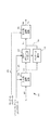
図1は、本発明のある実施形態による、EDR画像(また、HDR画像と呼ぶこともある)のディスプレイマネジメント処理の一例を表す。本処理は、2014年2月13日付け出願のPCT出願シリアル番号第PCT/US2014/016304号(以下、「‘304出願」と呼ぶ)に記載されたディスプレイマネジメント処理と多くの類似点を共有しており、この出願の開示内容を全て本願に援用する。但し、提案される実施形態は複数の改良点を含み、これにより、演算的な複雑さを低減しつつも、全体的な画質を向上させることが可能となる。
Display Management Processing Pipeline Example FIG. 1 illustrates an example of display management processing of an EDR image (also referred to as an HDR image) according to an embodiment of the present invention. This process shares many similarities with the display management process described in PCT application serial number PCT / US2014 / 016304 (hereinafter referred to as the '304 application) filed on February 13, 2014. The entire disclosure of this application is incorporated herein by reference. However, the proposed embodiment includes a plurality of improvements, which makes it possible to improve the overall image quality while reducing computational complexity.
図1に表わすように、ビデオプロセッサ(例えば、メディアサーバー、セットトップボックス、画像ディスプレイ、またはその他の適切な画像プロセッサ)は、EDR入力VI(102)ならびにオプションとして、付随するソースとコンテンツとのメタデータ(104)、およびターゲットメタデータ(106)を受信する。EDR入力(102)は、画像シーケンスが有するあるフレームの一部またはあるフレーム全体を含むことができ、例えばEDR映像信号などである。本明細書で用いるとき、「メタデータ」という用語は、符号化ビットストリームの一部として送信され、デコーダが復号化画像を描画するのに役立つ、任意の補助的情報に関する。このようなメタデータは、本明細書に記載の、色空間または色域の情報、リファレンスディスプレイパラメータ、および補助的信号パラメータを含み得るが、これらのみに限定はされない。 As shown in FIG. 1, a video processor (eg, a media server, set-top box, image display, or other suitable image processor) has an EDR input V I (102) and, optionally, associated source and content. The metadata (104) and the target metadata (106) are received. The EDR input (102) may include a part of a frame included in an image sequence or an entire frame, such as an EDR video signal. As used herein, the term “metadata” relates to any auxiliary information that is transmitted as part of the encoded bitstream and that helps the decoder render the decoded image. Such metadata may include, but is not limited to, color space or gamut information, reference display parameters, and auxiliary signal parameters as described herein.
受信されたEDR入力(102)は、RGB色形式で表現されていてもよいし、あるいはYCbCrやXYZなどの、その他任意の色空間にあってもよい。受信画像は、ターゲットディスプレイモニタとは異なったダイナミックレンジおよび色域上の特性を有し得るリファレンスEDRモニタにおいて、カラーグレーディングを施されていてもよい。本明細書で用いるとき、「カラーグレーディング」という用語は、「色のアーチファクトを補正するように、かつ/または制作意図に調和するように、画像または映像の色を調整する処理」を指す。 The received EDR input (102) may be expressed in RGB color format, or may be in any other color space, such as YCbCr or XYZ. The received image may be color graded on a reference EDR monitor that may have different dynamic range and color gamut characteristics than the target display monitor. As used herein, the term “color grading” refers to “a process of adjusting the color of an image or video to correct color artifacts and / or to match production intent”.
EDR入力(102)はまた、プログラム制作中に画像をカラーグレーディングするために使用されたディスプレイに関する、ソースディスプレイメタデータ(104)をも含み得る。例えば、このようなメタデータは、リファレンス電気−光学伝達関数(EOTF)(例えば、Rec.ITU−R BT.1866(03/2011)またはSMPTE ST 2084:2014)を含むことができる。EDR入力はまた、ソースディスプレイまたはリファレンスディスプレイの最大および最小輝度、データの最大、最小、および平均的ミッドトーン、ならびにカラーグレーディング時の周囲光強度などの、追加的なソースディスプレイとコンテンツとのメタデータ(104)を含んでいてもよい。例えば、リファレンスモニタについてのメタデータは、制作に使用された以下のようなパラメータ例を含み得る。すなわち、
ソースモニタ最小輝度、Smin=0.005ニト
ソースモニタ最大輝度、Smax=4000ニト
周囲光、Samb=10ニト
ガンマ、Sgamma=2.4
色空間=DCI P3、白色点=D65
である。
The EDR input (102) may also include source display metadata (104) regarding the display used to color-grade the image during program creation. For example, such metadata may include a reference electro-optical transfer function (EOTF) (eg, Rec. ITU-R BT. 1866 (03/2011) or SMPTE ST 2084: 2014). EDR input also provides additional source display and content metadata such as maximum or minimum brightness of the source or reference display, maximum, minimum, and average midtones of data, and ambient light intensity during color grading. (104) may be included. For example, the metadata about the reference monitor may include the following example parameters used for production. That is,
Source monitor minimum brightness, Smin = 0.005 nits Source monitor maximum brightness, Smax = 4000 nits Ambient light, Samb = 10 nits Gamma, Sgamma = 2.4
Color space = DCI P3, white point = D65
It is.
リファレンスモニタについてのメタデータは、典型的には一度のみ送信すればよい。しかし、映像データについてのメタデータは、フレーム毎に、シーン毎に、あるいは変化がある度に、送信することができる。もしもソースコンテンツに関するメタデータが無いならば、いくつかの実施形態において、このようなデータは、ソース映像コンテンツを解析することによって抽出できる。ターゲットメタデータ(106)は、ターゲットディスプレイによって供給され、ターゲットディスプレイ特性(例えば、最大輝度、色域など)を表現し得る。 The metadata about the reference monitor typically needs to be transmitted only once. However, metadata about video data can be transmitted for each frame, for each scene, or whenever there is a change. If there is no metadata about the source content, in some embodiments, such data can be extracted by analyzing the source video content. Target metadata (106) is provided by the target display and may represent target display characteristics (eg, maximum brightness, color gamut, etc.).
IPT−PQ色空間
ある好適な実施形態において、処理パイプライン(100)は、知覚的量子化IPTまたはIPT−PQ色空間と呼ぶことにする色空間において実行する。但し、同様な処理ステップを、線形RGB、ガンマRGB、YCbCr、XYZ、CIE−Labなどの、他の色空間において実行してもよい。本発明者の理解によると、IPT−PQ色空間において演算処理を行なえば、ディスプレイマネジメントパイプラインを固定小数点で、かつより低いビット深度において実行することや、トーンマッピングおよび色域マッピングの演算による色のアーチファクトを低減することなどの、数々の利点が提供される。本願にその全文が援用される、F.EbnerおよびM.D.Fairchildによる「Development and testing of a color space (ipt) with improved hue uniformity」、Proc.6th Color Imaging Conference: Color Science, Systems, and Applications, IS&T, Scottsdale, Arizona、1998年11月、8〜13ページ(以下、「Ebner論文」と呼ぶ)に記載のIPTは、人間の視覚システムにおける錐体間の色差のモデルである。その意味ではYCbCrまたはCIE−Lab色空間のようであるが、いくつかの科学的研究において、これらの空間よりも人間の視覚処理をより良く模擬することが分かっている。CIE−Labと同様に、IPTは、何らかの参照輝度に対する正規化された空間である。ある実施形態において、正規化は、ターゲットディスプレイの最大輝度に基づく。
IPT-PQ Color Space In a preferred embodiment, the processing pipeline (100) runs in a color space that will be referred to as a perceptual quantized IPT or IPT-PQ color space. However, similar processing steps may be performed in other color spaces such as linear RGB, gamma RGB, YCbCr, XYZ, CIE-Lab. According to the inventor's understanding, if an arithmetic process is performed in the IPT-PQ color space, the display management pipeline is executed at a fixed point and at a lower bit depth, and the color by the calculation of tone mapping and gamut mapping is used. Numerous benefits are provided, such as reducing artifacts. Which is incorporated herein by reference in its entirety. Ebner and M.M. D. "Development and testing of a color space (ipt) with implied hue uniformity" by Fairchild, Proc. 6th Color Imaging Conference: Color Science, Systems, and Applications, IS & T, Scottsdale, Arizona, November 1998, pages 8-13 (hereinafter referred to as “Ebner paper”) It is a model of color difference between bodies. In that sense, it seems to be a YCbCr or CIE-Lab color space, but in some scientific studies it has been shown to better simulate human visual processing than these spaces. Similar to CIE-Lab, IPT is a normalized space for some reference luminance. In some embodiments, normalization is based on the maximum brightness of the target display.
本明細書において、用語「PQ」は知覚的量子化を指す。人間の視覚システムは、光レベルの増大に対して非常に非線形的に反応する。人間が刺激を視る能力は、その刺激の輝度、その刺激の大きさ、その刺激を構成する空間周波数、および、その刺激を見ている瞬間までに目が適応した輝度レベルに影響される。好適な実施形態において、知覚的量子化器関数は、線形入力グレイレベルを、人間の視覚システムにおけるコントラスト感度閾値によりマッチした出力グレイレベルにマッピングする。PQマッピング関数の一例は、J.S.Millerらによる2012年12月06日出願の「Perceptual luminance nonlinearity−based image data exchange across different display capabilities」という表題のPCT出願シリアル番号第PCT/US2012/068212号(以下、「‘212出願」と呼ぶ)に記載されており、この出願の開示内容を全て本願に援用する。ある固定刺激サイズに対し、それぞれの輝度レベル(即ち、刺激レベル)について、最高感度の適応レベルおよび最高感度の空間周波数(HVSモデルによる)に応じて、その輝度レベルにおける最小可視コントラストステップを選択する。物理的な陰極線管(CRT)装置の応答曲線を表しており、人間の視覚システムの応答の仕方に対して非常に大まかな意味での類似性を偶然有し得る従来のガンマ曲線と比較すると、‘212出願において決定されているPQ曲線は、比較的シンプルな関数モデルを用いながら人間の視覚システムの真の視覚応答を模擬している。 As used herein, the term “PQ” refers to perceptual quantization. The human visual system responds very nonlinearly to increased light levels. The ability of a human to see a stimulus is affected by the brightness of the stimulus, the magnitude of the stimulus, the spatial frequencies that make up the stimulus, and the brightness level to which the eye has adapted by the moment that the stimulus is viewed. In a preferred embodiment, the perceptual quantizer function maps a linear input gray level to an output gray level that is matched by a contrast sensitivity threshold in the human visual system. An example of a PQ mapping function is J.I. S. PCT application serial number PCT / US2012 / 68 and below, entitled “Perceptual luminance non-linearity-based image exchange active display display capabilities” filed Dec. 06, 2012 by Miller et al. The entire disclosure of this application is incorporated herein by reference. For a fixed stimulus size, for each brightness level (ie, stimulus level), select the minimum visible contrast step at that brightness level depending on the highest sensitivity adaptation level and the highest sensitivity spatial frequency (according to the HVS model) . It represents the response curve of a physical cathode ray tube (CRT) device, compared to a conventional gamma curve, which can have a very rough similarity to how the human visual system responds, The PQ curve determined in the '212 application simulates the true visual response of the human visual system using a relatively simple functional model.
PQ曲線に基づくEOTFの一例が、SMPTE ST 2084:2014「High Dynamic Range EOTF of Mastering Reference Displays」において規定されており、この文献の開示内容を全て本願に援用する。知覚的量子化EOTFのもう一つの例が、J.Stessen他による「Chromaticity based color signals for wide color gamut and high dynamic range」、2014年10月、ISO/IEC JTC1/SC29/WG11 MPEG2014/M35065において提示されており、この文献の開示内容を全て本願に援用する。 An example of an EOTF based on a PQ curve is defined in SMPTE ST 2084: 2014 “High Dynamic Range EOTF of Mastering Reference Displays”, the entire disclosure of which is incorporated herein by reference. Another example of perceptual quantization EOTF is J. Presented in "Chromaticity based color signals for wide color gauge and high dynamic range" by Stessen et al. In October 2014, the contents of which are disclosed in this document by ISO / IEC JTC1 / SC29 / WG11 MPEG65 / 350. To do.
表1は、表示時点においてデジタルビデオ符号値を絶対線形輝度レベルに変換するための知覚的曲線EOTFの計算を示している。絶対線形輝度をデジタル符号値に変換するための逆EOTF(OETF)の計算も含まれている。
(表1)
例示的な等式定義:
D=知覚的曲線デジタル符号値、SDI−legal符号無し整数、10または12ビット
b=デジタル信号表現における成分毎のビット数、10または12
V=正規化された知覚的曲線信号値、0≦V≦1
Y=正規化された輝度値、0≦Y≦1
L=絶対輝度値、0≦L≦10,000cd/m2
例示的なEOTF復号化等式:

備考:
1.演算子INTは、0〜0.4999...の範囲の小数部に対しては値0を返し、0.5〜0.9999...の範囲の小数部に対しては+1を返す(即ち、0.5以上の小数部は切り上げ)。
2.丸めの問題を回避するために、定数は全て12ビット有理数の正確な倍数として定義する。
3.R、GまたはB信号成分は、上記のY信号成分と同じ方法で算出する。
Table 1 shows the calculation of the perceptual curve EOTF to convert the digital video code value to an absolute linear luminance level at the time of display. Also included is an inverse EOTF (OETF) calculation to convert the absolute linear luminance into a digital code value.
(Table 1)
Example equation definition:
D = Perceptual curve digital code value, SDI-legal unsigned integer, 10 or 12 bits b = Number of bits per component in digital signal representation, 10 or 12
V = normalized perceptual curve signal value, 0 ≦ V ≦ 1
Y = normalized luminance value, 0 ≦ Y ≦ 1
L = absolute luminance value, 0 ≦ L ≦ 10,000 cd / m 2
Exemplary EOTF decoding equation:
Remarks:
1. The operator INT is 0 to 0.4999. . . The value 0 is returned for the decimal part of the range of 0.5 to 0.9999. . . +1 is returned for the decimal part of the range (that is, the decimal part of 0.5 or more is rounded up).
2. To avoid rounding problems, all constants are defined as exact multiples of 12-bit rational numbers.
3. The R, G or B signal component is calculated by the same method as the Y signal component described above.
図2は、ある実施形態による色変換ステップ(110)の処理例を、より詳細に表わしている。図2に示すように、第1の色形式(例えば、YCbCr4:2:0またはRGBガンマ4:4:4)で表現された入力EDR信号VI(102)が与えられると、これを、色空間変換ステップ(110)において、知覚的に補正されたIPT色空間(IPT−PQ)における信号VIL(112)へと変換する。この色変換は、以下のステップを含み得る。すなわち、
a)ステップ(215)において、必要ならば、クロマ(色度)アップサンプリングその他の前処理演算(例えば、範囲(0,1)に納まるように入力をスケーリングする)を実行して、出力(217)を生成し得る。
b)入力EDR信号(102)は、ガンマ符号化またはPQ符号化されている可能性があり、そのいずれであるかは、典型的にはソースメタデータ(104)を使用して示される(signaled)。ステップ(220)において、EOTF(メタデータ(104)によって提供される)を使用して、ソースディスプレイによる符号化値から輝度への変換を、逆転あるいは元に戻すことができる。例えば、もしも入力信号がガンマ符号化されているならば、本ステップは、逆ガンマ関数を適用する。もしも入力信号がPQ符号化(例えば、SMPTE ST 2084に従って)されているのならば、本ステップは、逆PQ関数を適用する。実際には、3つの予め算出された1−Dルックアップテーブル(LUT)を用いて、この線形化ステップ(220)を実行し得る。
c)ステップ(225)において、線形化信号(222)をLMS色空間における信号(227)へと変換する。典型的には、本ステップは、a)標準的な変換を用いて、入力をXYZ色空間へと変換し、その後に3×3行列を適用してXYZからLMSへと信号を変換することによって、実行される。
d)(ステップ230)。Ebner論文によると、従来のLMSからIPTへの色空間変換は、LMSデータに対し先ず非線形べき関数を適用することと、その後に線形変換行列を適用することとを含む。データをLMSからIPTへと変換し、その後にPQ関数を適用してIPT−PQ領域に置いてもよいのだが、ある好適な実施形態では、ステップ(230)において、LMSからIPTへの非線形符号化用の従来のべき関数を、PQ非線形符号化で代替する。例えば、非線形のL、M、およびS値は、等式(t2)におけるV信号と同様に算出される。但し、Y信号は、線形のL、M、またはS成分値で置き換える。いくつかの実施形態において、PQ符号化の正規化バージョンを用いてもよく、このとき等式(t3)のステップを省略でき、出力PQ値の範囲は0と1の間である。いくつかの実施形態において、別のPQ符号化(例えば、Stessenによって提案されたものなど)を適用することも、また可能である。
e)標準的なLMSからIPTへの3×3線形変換を用いて、ステップ(235)が、信号(102)に対するIPT−PQ色空間への変換を完成する。
FIG. 2 illustrates in more detail an example process of the color conversion step (110) according to an embodiment. As shown in FIG. 2, given an input EDR signal V I (102) expressed in a first color format (eg, YCbCr 4: 2: 0 or RGB gamma 4: 4: 4), In the space conversion step (110), the signal V IL (112) in the IPT color space (IPT-PQ) corrected perceptually is converted. This color conversion may include the following steps. That is,
a) In step (215), if necessary, perform chroma (chromaticity) upsampling and other preprocessing operations (eg, scale the input to fit in the range (0,1)) and output (217) ) May be generated.
b) The input EDR signal (102) may be gamma encoded or PQ encoded, which is typically indicated using the source metadata (104) ). In step (220), EOTF (provided by metadata (104)) can be used to reverse or reverse the conversion from encoded value to luminance by the source display. For example, if the input signal is gamma encoded, this step applies an inverse gamma function. If the input signal is PQ encoded (eg according to SMPTE ST 2084), this step applies an inverse PQ function. In practice, this linearization step (220) may be performed using three pre-calculated 1-D look-up tables (LUTs).
c) In step (225), the linearized signal (222) is converted to a signal (227) in the LMS color space. Typically, this step consists of: a) using standard transformations to transform the input to XYZ color space, followed by applying a 3x3 matrix to transform the signal from XYZ to LMS. Executed.
d) (Step 230). According to the Ebner paper, conventional LMS to IPT color space conversion involves first applying a non-linear power function to the LMS data and then applying a linear transformation matrix. Although the data may be converted from LMS to IPT and then applied to the PQ function and placed in the IPT-PQ domain, in a preferred embodiment, in step (230), a non-linear code from LMS to IPT The conventional power function for encoding is replaced with PQ nonlinear encoding. For example, the nonlinear L, M, and S values are calculated in the same manner as the V signal in equation (t2). However, the Y signal is replaced with a linear L, M, or S component value. In some embodiments, a normalized version of PQ encoding may be used, in which case the step of equation (t3) can be omitted and the range of output PQ values is between 0 and 1. In some embodiments, it is also possible to apply another PQ encoding (eg, as proposed by Stepssen).
e) Using a standard LMS to IPT 3 × 3 linear transformation, step (235) completes the transformation of the signal (102) to the IPT-PQ color space.
いくつかの実施形態において、完全な色変換パイプライン(例えば、110)を、3DのLUTを使用して算出し得る。さらに、入力信号が既にIPT−PQ空間にある実施形態において、入力色空間変換(110)は、スキップされ得る。 In some embodiments, a complete color conversion pipeline (eg, 110) may be calculated using a 3D LUT. Further, in embodiments where the input signal is already in IPT-PQ space, the input color space conversion (110) may be skipped.
カラーボリュームマッピング
色変換ステップ(110)の後で、信号VIL(112)の明度(IO)およびクロマ(P/T)をマッピングして、ターゲットディスプレイの制約内に納める必要がある。図3は、ある実施形態による、カラーボリュームマッピング処理(115)の実装例を表している。カラーボリュームマッピング処理(115)の最初の部分において、色を暗くする量を、その彩度(saturation)と明度の両方に基づいて決定する。ある実施形態において、限定することなく、彩度のメトリックSは、クロマ成分の2乗和すなわち、
![]()
![]()
トーンマッピング関数(310)は、入力データVIL(112)の明度IO(302)に非線形マッピングを適用して、トーンマッピングされた明度データIm(314)(例えば、Im=fT(IO))を生成する。非線形マッピング変換の一例が、A.Ballestad他による「Method and apparatus for image data transformation」という表題の米国特許第8,593,480号(以下、「‘480特許」と呼ぶ)に記載されており、この特許の開示内容を全て本願に援用する。 The tone mapping function (310) applies non-linear mapping to the lightness I O (302) of the input data V IL (112) to generate tone-mapped lightness data I m (314) (eg, I m = f T ( I O )). An example of a non-linear mapping transformation is A.I. US Pat. No. 8,593,480 (hereinafter referred to as the “'480 patent”) entitled “Method and apparatus for image data transformation” by Ballestad et al., The entire disclosure of which is incorporated herein by reference. Incorporate.
‘480特許によると、非線形マッピングのための伝達関数の一例は、
トーンマッピングにおけるキー概念は、ミッドポイントの明度およびコントラストに対して可能な限りほとんど変化を加えないことにより、全体的な画像の外観を保存することである。シャドーおよびハイライトは、このとき、ターゲットディスプレイの輝度範囲へと滑らかにマッピングされる。ある実施形態例において、ステップ(310)により、等式(2)のトーン曲線パラメータを以下のように算出し得る。すなわち、TminおよびTmaxは、PQ符号化で表現された、ターゲットディスプレイの最小および最大輝度を表すものとする。また、SminおよびSmaxは、やはりPQ符号化された、ソースディスプレイの最小および最大輝度を表すものとする。このとき、ある実施形態において、S2Tratioは、
S2Tratioが与えられると、ある実施形態において、
ある実施形態において、Rolloff=1/3という値が主観的に決定されており、広範な画像について良好な画質を提供できる。 In some embodiments, a value of Rolloff = 1/3 is determined subjectively and can provide good image quality over a wide range of images.
等式(2〜4)が与えられると、パラメータC1、C2、およびC3は、特定の最小、最大、および中間の制御点を通るようなトーンマッピング曲線を決定する連立方程式を解くことにより、導出できる。
いくつかの実施形態において、例えばより明るい、またはより暗い視聴環境へとマッピングするときに、上記のトーン曲線に対する変更が望まれることがある。これについては、主観的に調整することが可能な2つの追加的なパラメータを介して対処し得る。すなわち、ContrastとBrightnessである。ContrastおよびBrightnessが与えられると、等式(4)における当初のShiftおよびSlopeパラメータは、
Brightness制御は、ターゲットディスプレイのダイナミックレンジ次第ではミッドポイントのみにしか影響を与えないこともあるが、当該画像全体の輝度をグローバルに上げたり下げたりする効果を有する。Contrast制御は、ターゲットディスプレイのダイナミックレンジ次第ではシャドーまたはハイライトにおけるコントラストを減少させることもあるが、ミッドポイントの周囲のコントラストを上げたり下げたりする効果を有する。 The Brightness control may affect only the midpoint depending on the dynamic range of the target display, but has the effect of increasing or decreasing the brightness of the entire image globally. Contrast control has the effect of raising or lowering the contrast around the midpoint, although it may reduce contrast in shadows or highlights depending on the dynamic range of the target display.
BrightnessおよびContrast制御を変更することにより、2つの目的を達成することが可能である。第1に、これらをエンドディスプレイにおいて調整することにより、異なる視聴環境に対する補償を行なえる。このことは、PLUGEタイプの演算を介して行なわれ、ユーザーは、黒と白とのディテールが画像において主観的に可視となるまで、輝度および/またはコントラストを調整する。これらのパラメータの第2の用途は、ある特定の場面(shot)につき、デフォルトのマッピングを微調整するメタデータの一部としてであり、これにより、ある特定の主観的印象が達成される。 By changing the Brightness and Contrast controls, two objectives can be achieved. First, they can be adjusted at the end display to compensate for different viewing environments. This is done via a PLUGE type operation where the user adjusts the brightness and / or contrast until the black and white details are subjectively visible in the image. The second use of these parameters is as part of the metadata that fine-tunes the default mapping for a particular shot, thereby achieving a certain subjective impression.
上記のC1、C2、およびC3パラメータが与えられると、ある実施形態において、マッピングされた明度は、
実際において、トーンマッピングされた画像(314)を算出することは、典型的には、ルックアップテーブルを用いて実施する。 In practice, calculating the tone mapped image (314) is typically performed using a look-up table.
図3に表わすように、カラーボリュームマッピング(115)は彩度マッピング関数(320)を含み、これを使用することにより、明度の変化に基づいてクロマ値(P/T)(304)を調整する。色の明度を低減させるとき、その彩度をもまた、外観やバランスを維持するように減少させる。ある実施形態において、彩度マッピング(320)は、
![]()
![]()
トーンマッピング曲線および彩度曲線は、特定のソースディスプレイ性能およびターゲットディスプレイ性能につき、ならびにオプションとして任意のユーザー調整につき、算出される。ひとたび算出し終えると、これらを各画素に個別に適用することにより、ソースカラーボリュームからターゲットカラーボリュームへとマッピングを行なうことが可能である。手順の中核となるのは、まず、トーン曲線を入力明度に適用し、次に、彩度曲線によって各クロマチャネルをスケーリングすることである。同一のスケーリング係数を両クロマチャネルに適用することにより、色相を保存する(色相はIPTにおいてPとTとの間の角度として規定される)。従って、ある実施形態において、
このことは一般に、ターゲットディスプレイのカラーボリュームに最終的に納まる色については、良好な結果を生む。しかし、ターゲットディスプレイは明るい飽和色を生成し得ないこともあるという事実には対処していない。この場合、本発明者の理解によると、何らかのさらなるクロマ調整が必要となり得る。 This generally yields good results for colors that will eventually fit in the color volume of the target display. However, it does not address the fact that the target display may not be able to produce bright saturated colors. In this case, according to the inventor's understanding, some further chroma adjustment may be required.
カラーボリュームマッピングの後で、ターゲットディスプレイのカラーボリュームの外側に取り残される任意の色は、RGB空間においてクリッピングされることになり、これによってアーチファクトが発生し得る。外側に取り残される色を低減するために、ある実施形態において、色をターゲットディスプレイのカラーボリューム中へとさらにマッピングする2つの手段が提供される。第1の手段は、明るい飽和色を暗くすることであり、第2の手段は、飽和度が高い色の飽和度を下げることである。このとき、等式(9)のカラーボリュームマッピング手順は、以下に示すように変更できる。すなわち、
等式(10)において、まず、画素彩度Sを算出し、適応的色域マッピングのためのマスクとして使用する。これにより、飽和度の高い色は最も大きく影響を受けつつも無彩に近い色は影響を受けないことになる。色の明度は、その彩度と明度の両方に従って、ある量αによって調整される。同様に、彩度は、彩度および別の量βに従って調整される。これらの2方向間の重みを指定することにより、カラーボリュームマッピング方針を制御して、出力画像において色の精度を改善し、かつ色のアーチファクトを低減することが可能である。最大の調整は、明るい飽和色に対して適用される。ある実施形態において、これらの重みの典型的な値は、5から15までの範囲に亘る。ある実施形態において、等式(10)はまた、(1−S*α)および(1−S*b)の値がマイナスにもゼロにも決してならないように、クリッピング演算を含んでもよい。 In equation (10), the pixel saturation S is first calculated and used as a mask for adaptive gamut mapping. As a result, a highly saturated color is most affected, but an achromatic color is not affected. The lightness of a color is adjusted by a certain amount α according to both its saturation and lightness. Similarly, the saturation is adjusted according to the saturation and another amount β. By specifying weights between these two directions, it is possible to control the color volume mapping strategy to improve color accuracy and reduce color artifacts in the output image. The maximum adjustment is applied to bright saturated colors. In certain embodiments, typical values for these weights range from 5 to 15. In some embodiments, equation (10) may also include a clipping operation such that the values of (1−S * α) and (1−S * b) are never negative or zero.
もう一つの実施形態において、等式(10)は、
ディテールの保存
等式(4)のトーンマッピング作用素(operator)は、画像またはフレームの全体に同一の等式を適用するので、典型的には、グローバルトーンマッピング作用素と呼ばれる。ある実施形態において、グローバルトーンマッピングの後には、ディテール保存作用素(125)が続くことができ、ローカルなコントラストを改善する。このステップはまた、トーンマッピング演算のせいで失われた、明度チャネルにおける高周波数のディテールを復元する。このようなローカルトーンマッピング作用素の例が、‘480特許および‘304出願に記載されている。図4は、ある実施形態による、ディテール保存のもう一つの例を表す。入力Io(302)およびIm(314)、ならびにソースメタデータ(104)が与えられると、処理(125)において、フィルタリングされた明度の画像Imf(127)を、以下のステップに従って生成する。
Preserving Detail The tone mapping operator in equation (4) is typically referred to as the global tone mapping operator because it applies the same equation to the entire image or frame. In some embodiments, the global tone mapping can be followed by a detail preservation operator (125) to improve local contrast. This step also restores the high frequency details in the lightness channel that were lost due to the tone mapping operation. Examples of such local tone mapping operators are described in the '480 patent and the' 304 application. FIG. 4 illustrates another example of detail storage according to an embodiment. Given inputs I o (302) and I m (314), and source metadata (104), in process (125) a filtered brightness image I mf (127) is generated according to the following steps: .
WMSEおよびWMSは、調整可能な重み(例えば、WMS=1,WMSE=4)を表すものとする。これらはソースメタデータから抽出し得る。これらの重みによって、適用されるべきディテール保存の量を制御する。図4に表わすように、
フィルタHxおよびHyは、1−Dのエッジ検出フィルタである。ある実施形態において、HxおよびHyのフィルタカーネルは、それぞれ、[−1 0 1]および[−1 0 1]Tに対応する。ゆえに、
出力色変換
図5は、マッピングされたEDR信号VM(Im,Pm,TmまたはImf,Pm,Tm成分を含む)を、知覚的量子化色空間(例えば、IPT−PQ)から所望の色空間(例えば、RGBまたはYCbCr)へと変換し戻す色変換処理(135)の一例を表している。本処理は、入力色変換器(110)における処理ステップを反映しており、今度は逆順で実行される。図5に表わすように、色変換は、以下のステップを含み得る。すなわち、
a)ステップ(505):3×3のIPTからLMSへの変換を使用して、マッピング信号VMを、IPT−PQ空間からLMS−PQ空間へと変換する。
b)ステップ(510):LMS−PQ信号(507)を、LMS−PQ空間からLMS空間へと変換する。本ステップは、表1の等式を使用して算出される。ある実施形態において、本ステップは、3つの1−DのLUTを使用して実行できる。
c)ステップ(515):LMS信号(512)を、ターゲットディスプレイ色(例えば、RGB)(517)へと変換する。典型的には、ターゲットディスプレイの特性(profile)に基づき、3×3行列を使用して実行される。
d)ステップ(520):信号(517)にディスプレイのEOTF(例えば、ガンマまたはPQ符号化)を適用して、出力信号(522)を生成する。
e)ステップ(525):必要ならば、追加的な後処理(例えば、色変換および色サブサンプリング)を適用する。
Output Color Conversion FIG. 5 illustrates mapping a mapped EDR signal V M (including I m , P m , T m or I mf , P m , T m components) to a perceptual quantization color space (eg, IPT-PQ). ) Represents an example of color conversion processing (135) for converting back to a desired color space (for example, RGB or YCbCr). This process reflects the processing steps in the input color converter (110) and is now performed in reverse order. As shown in FIG. 5, the color conversion may include the following steps. That is,
a) Step (505): from 3 × 3 IPT using conversion to LMS, the mapping signal V M, and converts the IPT-PQ space into LMS-PQ space.
b) Step (510): Transform the LMS-PQ signal (507) from LMS-PQ space to LMS space. This step is calculated using the equation in Table 1. In certain embodiments, this step can be performed using three 1-D LUTs.
c) Step (515): Convert the LMS signal (512) to the target display color (eg, RGB) (517). Typically, this is done using a 3x3 matrix based on the target display profile.
d) Step (520): Apply EOTF (eg, gamma or PQ encoding) of the display to signal (517) to generate output signal (522).
e) Step (525): Apply additional post-processing (eg color conversion and color subsampling) if necessary.
本ステップは、純粋に測色学的(colorimetric)である。すなわち、諸パラメータは、測定または既知のディスプレイ仕様から導出され、チューニングも主観的補正も、典型的には全く不要である。段(520)の後で、ターゲットディスプレイ性能の外側に、値がいくつか残っていることがある。この場合、推奨される習慣としては、ディスプレイ性能に合わせてクリッピングを行なう。但し、カラーボリュームマッピングの重み(例えば、αおよびβ)を調整することにより、所望の出力を達成しようと試みることもまた可能である。 This step is purely colorimetric. That is, the parameters are derived from measured or known display specifications, and typically no tuning or subjective correction is required. After stage (520), some values may remain outside the target display performance. In this case, as a recommended practice, clipping is performed according to the display performance. However, it is also possible to attempt to achieve the desired output by adjusting the color volume mapping weights (eg, α and β).
発明者の理解によると、提案されたディスプレイマネジメントパイプライン(100)において、先行するソリューションに勝る、以下を含む数々の別個の利点が提供される。
・適応的なトーンマッピング
・適応的な色域マッピング
・調整可能なクロマ関連の重みによる、より優れた出力色精度
・演算的により単純な、しかし改良された、ディテール保存
・ターゲットディスプレイの視聴環境(周囲光特性や視聴者の嗜好など)に基づいた、適応的調整(例えば、輝度およびコントラストについての)
According to the inventor's understanding, the proposed display management pipeline (100) offers a number of distinct advantages over previous solutions, including:
• Adaptive tone mapping • Adaptive color gamut mapping • Better output color accuracy with adjustable chroma-related weights • Computationally simpler but improved detail storage • Target display viewing environment ( Adaptive adjustments based on ambient light characteristics, viewer preferences, etc. (eg for brightness and contrast)
コンピュータシステム実装例
本発明の実施形態は、コンピュータシステム、電子回路およびコンポーネントで構成されたシステム、マイクロコントローラ、フィールドプログラマブルゲートアレイ(FPGA)または他のコンフィギュラブルまたはプログラマブルロジックデバイス(PLD)、離散時間またはデジタル信号プロセッサ(DSP)、特定用途向けIC(ASIC)などの集積回路(IC)デバイス、および/または、このようなシステム、デバイスまたはコンポーネントを1つ以上含む装置、を用いて実施し得る。このコンピュータおよび/またはICは、本明細書に記載のエンハンストダイナミックレンジを備える画像のディスプレイマネジメントおよび表示に関する命令を実施し、制御し、または実行し得る。コンピュータおよび/またはICは、本明細書に記載のディスプレイマネジメントプロセスに関係する様々なパラメータや値の内のいずれを演算してもよい。画像およびビデオ実施形態は、ハードウェア、ソフトウェア、ファームウェア、および、その様々な組み合わせで実施され得る。
Embodiments of Computer Systems Embodiments of the present invention include computer systems, systems composed of electronic circuits and components, microcontrollers, field programmable gate arrays (FPGAs) or other configurable or programmable logic devices (PLDs), discrete time Alternatively, it may be implemented using a digital signal processor (DSP), an integrated circuit (IC) device such as an application specific IC (ASIC), and / or an apparatus that includes one or more such systems, devices or components. The computer and / or IC may implement, control, or execute instructions relating to display management and display of images with the enhanced dynamic range described herein. The computer and / or IC may compute any of a variety of parameters and values related to the display management process described herein. Image and video embodiments may be implemented in hardware, software, firmware, and various combinations thereof.
本発明の特定の態様は、本発明の方法をプロセッサに行わせるためのソフトウェア命令を実行するコンピュータプロセッサを含む。例えば、ディスプレイ、エンコーダ、セットトップボックス、トランスコーダなどの中の1つ以上のプロセッサは、そのプロセッサがアクセス可能なプログラムメモリ内にあるソフトウェア命令を実行することによって、上記のようなEDR画像のディスプレイマネジメントに関する方法を実施し得る。本発明は、プログラム製品形態で提供されてもよい。このプログラム製品は、データプロセッサによって実行された時に本発明の方法をデータプロセッサに実行させるための命令を含む1セットのコンピュータ可読信号を格納する任意の非一時的媒体を含み得る。本発明によるプログラム製品は、様々な形態をとり得る。例えば、このプログラム製品は、フロッピーディスケット、ハードディスクドライブを含む磁気データ記憶媒体、CD ROM、DVDを含む光学データ記憶媒体、ROM、フラッシュRAMなどを含む電子データ記憶媒体、などの物理的媒体を含み得る。このプログラム製品上のコンピュータ可読信号は、任意に、圧縮または暗号化されていてもよい。 Particular aspects of the present invention include computer processors that execute software instructions to cause a processor to perform the methods of the present invention. For example, one or more processors in a display, encoder, set-top box, transcoder, etc. can display an EDR image as described above by executing software instructions in a program memory accessible to the processor. Management methods can be implemented. The present invention may be provided in the form of a program product. The program product may include any non-transitory medium that stores a set of computer readable signals that include instructions for causing the data processor to perform the methods of the invention when executed by the data processor. The program product according to the present invention may take various forms. For example, the program product may include physical media such as floppy diskettes, magnetic data storage media including hard disk drives, optical data storage media including CD ROM, DVD, electronic data storage media including ROM, flash RAM, and the like. . The computer readable signal on the program product may optionally be compressed or encrypted.
上記においてあるコンポーネント(例えば、ソフトウェアモジュール、プロセッサ、アセンブリ、デバイス、回路など)に言及している場合、そのコンポーネントへの言及(「手段」への言及を含む)は、別途示唆のない限り、当該コンポーネントの機能を果たす(例えば、機能的に均等である)あらゆるコンポーネント(上記した本発明の実施形態例に出てくる機能を果たす開示された構造に対して構造的に均等ではないコンポーネントも含む)を、当該コンポーネントの均等物として、含むものと解釈されるべきである。 Where reference is made to a component (eg, a software module, processor, assembly, device, circuit, etc.) above, references to that component (including references to “means”), unless otherwise indicated, Any component that performs the function of the component (eg, is functionally equivalent) (including components that are not structurally equivalent to the disclosed structures that perform the functions that appear in the example embodiments of the present invention described above) Should be construed as including the equivalent of that component.
均等物、拡張物、代替物、その他
EDR画像の効率的なディスプレイマネジメントに関する実施形態例を上述した。この明細書中において、態様毎に異なり得る多数の詳細事項に言及しながら本発明の実施形態を説明した。従って、本発明が何たるか、また、本出願人が本発明であると意図するものを示す唯一且つ排他的な指標は、本願が特許になった際の請求の範囲(今後出されるあらゆる訂正を含む、特許となった特定請求項)である。当該請求項に含まれる用語に対して本明細書中に明示したあらゆる定義が、請求項内で使用される当該用語の意味を決定するものとする。よって、請求項において明示されていない限定事項、要素、性質、特徴、利点または属性は、その請求項の範囲をいかなる意味においても限定すべきではない。従って、本明細書および図面は、限定的ではなく、例示的であるとみなされるものである。
Equivalents, extensions, alternatives, etc. Embodiments have been described above for efficient display management of EDR images. In this specification, embodiments of the invention have been described with reference to numerous details that may vary from aspect to aspect. Therefore, the only and exclusive indication of what the present invention is and what the applicant intends to be the present invention is the scope of the claims as the patent was filed (including any future corrections). Including the patented specific claims). Any definitions expressly set forth herein for terms contained in such claims shall govern the meaning of such terms as used in the claims. Hence, no limitation, element, property, feature, advantage or attribute that is not expressly recited in a claim should limit the scope of that claim in any way. Accordingly, the specification and drawings are to be regarded as illustrative rather than restrictive.
Claims (17)
第1のダイナミックレンジを備えた第1の色空間における入力画像にアクセスする工程と、
前記入力画像に色変換ステップを適用して、知覚的量子化IPT(IPT−PQ)色空間における第1の出力画像を決定する工程であって、前記第1の出力画像は、明度画素値およびクロマ成分画素値を有しており、前記色変換ステップは、前記入力画像の関数に非線形な知覚的量子化器関数を適用する工程を含む、工程と、
前記第1の出力画像にカラーボリュームマッピング関数を適用して、トーンマッピングされた出力画像を生成する工程であって、前記トーンマッピングされた出力画像は、明度画素値およびクロマ成分画素値を有しており、
前記カラーボリュームマッピング関数は、トーンマッピング関数、彩度マッピング関数、および画素彩度推測関数を含み、
前記トーンマッピング関数は、前記第1の出力画像の前記明度画素値に非線形マッピングを適用することにより、前記トーンマッピングされた出力画像の前記明度画素値を生成し、
前記彩度マッピング関数は、明度の変化に基づいて前記第1の出力画像の前記クロマ成分画素値を調整することにより、前記トーンマッピングされた出力画像の前記クロマ成分画素値を生成し、
前記画素彩度推測関数は、前記第1の出力画像の前記クロマ成分画素値の2乗和として彩度メトリック(S)を算出し、前記彩度メトリックは、前記トーンマッピングされた出力画像に適用されて、明るい飽和色を暗くし、かつ、飽和度が高い色の飽和度を下げ、これにより、前記明度画素値および前記クロマ成分画素値を変更する、工程と
前記トーンマッピングされた出力画像の前記変更された明度画素値にディテール保存関数を適用して、トーンマッピングされフィルタリングされた出力画像の明度画素値を生成する工程であって、前記トーンマッピングされフィルタリングされた出力画像は、前記トーンマッピングされた出力画像の前記変更されたクロマ成分画素値を有する、工程。 A method comprising the following steps:
Accessing an input image in a first color space with a first dynamic range;
Applying a color conversion step to the input image to determine a first output image in a perceptual quantized IPT (IPT-PQ) color space, the first output image comprising: Having a chroma component pixel value, and wherein the color conversion step comprises applying a non-linear perceptual quantizer function to the function of the input image;
Applying a color volume mapping function to the first output image to generate a tone-mapped output image, the tone-mapped output image having a lightness pixel value and a chroma component pixel value; And
The color volume mapping function includes a tone mapping function, a saturation mapping function, and a pixel saturation estimation function,
The tone mapping function generates the lightness pixel value of the tone-mapped output image by applying a non-linear mapping to the lightness pixel value of the first output image;
The saturation mapping function generates the chroma component pixel value of the tone-mapped output image by adjusting the chroma component pixel value of the first output image based on a change in brightness,
The pixel saturation estimation function calculates a saturation metric (S) as a sum of squares of the chroma component pixel values of the first output image, and the saturation metric is applied to the tone-mapped output image. Darkening a bright saturated color and lowering the saturation of a highly saturated color, thereby changing the lightness pixel value and the chroma component pixel value, and the tone mapped output image Applying a detail preserving function to the modified brightness pixel value to generate a brightness pixel value of the tone mapped filtered output image, wherein the tone mapped filtered output image is the tone mapping Having the altered chroma component pixel value of the output image rendered.
前記入力画像から非線形符号化を除去して、線形画像を生成する工程と、
前記線形画像をLMS色画像に変換する工程と、
前記LMS色画像に前記非線形な知覚的量子化器(PQ)関数を適用して、前記第1の出力画像を生成する工程と、
を含む、請求項1に記載の方法。 The step of applying the color conversion step further includes
Removing nonlinear encoding from the input image to generate a linear image;
Converting the linear image into an LMS color image;
Applying the non-linear perceptual quantizer (PQ) function to the LMS color image to generate the first output image;
The method of claim 1 comprising:
前記カラーボリュームマッピング関数を適用する工程は、
Applying the color volume mapping function comprises:
Imは、前記トーンマッピングされた出力画像の前記明度画素値を表し、Imfは、前記トーンマッピングされフィルタリングされた出力画像の前記明度画素値を表し、Bはブラーフィルタの出力を表し、Exは水平エッジ検出フィルタの出力を表し、Eyは鉛直エッジ検出フィルタの出力を表し、WMSEおよびWMSは重みである、請求項1〜11のいずれかに記載の方法。 The step of applying the detail preservation function includes:
I m represents the lightness pixel value of the tone-mapped output image, I mf represents the lightness pixel value of the tone-mapped and filtered output image, B represents the output of a blur filter, Ex The method according to claim 1, wherein represents the output of a horizontal edge detection filter, Ey represents the output of a vertical edge detection filter, and W MSE and W MS are weights.
Applications Claiming Priority (3)
| Application Number | Priority Date | Filing Date | Title |
|---|---|---|---|
| US201562105139P | 2015-01-19 | 2015-01-19 | |
| US62/105,139 | 2015-01-19 | ||
| PCT/US2016/013352 WO2016118395A1 (en) | 2015-01-19 | 2016-01-14 | Display management for high dynamic range video |
Publications (2)
| Publication Number | Publication Date |
|---|---|
| JP2018510574A JP2018510574A (en) | 2018-04-12 |
| JP6362793B2 true JP6362793B2 (en) | 2018-07-25 |
Family
ID=55411728
Family Applications (1)
| Application Number | Title | Priority Date | Filing Date |
|---|---|---|---|
| JP2017549366A Active JP6362793B2 (en) | 2015-01-19 | 2016-01-14 | Display management for high dynamic range video |
Country Status (16)
| Country | Link |
|---|---|
| US (1) | US9961237B2 (en) |
| EP (1) | EP3248367B1 (en) |
| JP (1) | JP6362793B2 (en) |
| KR (2) | KR102117522B1 (en) |
| CN (1) | CN107211076B (en) |
| AU (1) | AU2016209615C1 (en) |
| CA (1) | CA2973909C (en) |
| ES (1) | ES2692444T3 (en) |
| IL (1) | IL253409B (en) |
| MX (1) | MX359721B (en) |
| PL (1) | PL3248367T3 (en) |
| RU (2) | RU2659485C1 (en) |
| SG (2) | SG11201705702XA (en) |
| TR (1) | TR201815542T4 (en) |
| WO (1) | WO2016118395A1 (en) |
| ZA (1) | ZA201704922B (en) |
Families Citing this family (51)
| Publication number | Priority date | Publication date | Assignee | Title |
|---|---|---|---|---|
| WO2016182307A1 (en) * | 2015-05-11 | 2016-11-17 | 삼성전자 주식회사 | Image processing apparatus and image processing method based on metadata |
| WO2016183239A1 (en) | 2015-05-12 | 2016-11-17 | Dolby Laboratories Licensing Corporation | Metadata filtering for display mapping for high dynamic range images |
| WO2017040237A1 (en) | 2015-08-28 | 2017-03-09 | Arris Enterprises Llc | Color volume transforms in coding of high dynamic range and wide color gamut sequences |
| US10140953B2 (en) * | 2015-10-22 | 2018-11-27 | Dolby Laboratories Licensing Corporation | Ambient-light-corrected display management for high dynamic range images |
| WO2018000126A1 (en) * | 2016-06-27 | 2018-01-04 | Intel Corporation | Method and system of multi-dynamic range multi-layer video blending with alpha channel sideband for video playback |
| CN116582675A (en) * | 2016-10-05 | 2023-08-11 | 杜比实验室特许公司 | Apparatus associated with processing of source color volume information |
| JP6789760B2 (en) * | 2016-10-31 | 2020-11-25 | キヤノン株式会社 | Imaging device and its control method, program, and storage medium |
| US10930223B2 (en) | 2016-12-22 | 2021-02-23 | Dolby Laboratories Licensing Corporation | Ambient light-adaptive display management |
| EP3367659A1 (en) * | 2017-02-28 | 2018-08-29 | Thomson Licensing | Hue changing color gamut mapping |
| EP3566429B1 (en) | 2017-03-03 | 2021-09-15 | Dolby Laboratories Licensing Corporation | Color image modification with approximation function |
| WO2018160847A1 (en) * | 2017-03-03 | 2018-09-07 | Dolby Laboratories Licensing Corporation | Color image modification with approximation function |
| EP3566430B1 (en) * | 2017-03-03 | 2022-10-12 | Dolby Laboratories Licensing Corporation | Color saturation adjustment in non-uniform color space |
| US11158032B2 (en) | 2017-03-20 | 2021-10-26 | Dolby Laboratories Licensing Corporation | Perceptually preserving scene-referred contrasts and chromaticities |
| WO2018175337A1 (en) | 2017-03-20 | 2018-09-27 | Dolby Laboratories Licensing Corporation | Perceptually preserving scene-referred contrasts and chromaticities |
| JP7141200B2 (en) * | 2017-03-27 | 2022-09-22 | 東芝ライテック株式会社 | Information processing system |
| CN107197266B (en) * | 2017-06-26 | 2020-05-15 | 杭州当虹科技股份有限公司 | HDR video coding method |
| JP6846307B2 (en) * | 2017-07-31 | 2021-03-24 | 日本放送協会 | Luminance adjustment signal generator and its program, and video display device |
| US11252401B2 (en) | 2017-08-07 | 2022-02-15 | Dolby Laboratories Licensing Corporation | Optically communicating display metadata |
| KR102525546B1 (en) * | 2017-11-21 | 2023-04-26 | 삼성디스플레이 주식회사 | Image processing method and image processor performing the same |
| EP3493542A1 (en) | 2017-11-30 | 2019-06-05 | Thomson Licensing | Saturation control for high-dynamic range reconstruction |
| BR112020010703A2 (en) * | 2017-12-12 | 2020-11-17 | Interdigital Vc Holdings, Inc. | processing an image |
| US10445865B1 (en) * | 2018-03-27 | 2019-10-15 | Tfi Digital Media Limited | Method and apparatus for converting low dynamic range video to high dynamic range video |
| JP7003304B2 (en) | 2018-06-18 | 2022-01-20 | ドルビー ラボラトリーズ ライセンシング コーポレイション | Imaging method and system |
| CN110691277B (en) | 2018-07-05 | 2024-03-05 | 华为技术有限公司 | Video signal processing method and device |
| CN112703529B (en) * | 2018-09-17 | 2022-05-31 | 杜比实验室特许公司 | Display mapping of high dynamic range images on power limited displays |
| US11503310B2 (en) * | 2018-10-31 | 2022-11-15 | Ati Technologies Ulc | Method and apparatus for an HDR hardware processor inline to hardware encoder and decoder |
| US11404025B2 (en) * | 2019-04-10 | 2022-08-02 | Mediatek Inc. | Video processing system for performing artificial intelligence assisted picture quality enhancement and associated video processing method |
| US11803948B2 (en) | 2019-04-23 | 2023-10-31 | Dolby Laboratories Licensing Corporation | Display management for high dynamic range images |
| EP3959646B1 (en) * | 2019-04-25 | 2023-04-19 | Dolby Laboratories Licensing Corporation | Content-aware pq range analyzer and tone mapping in live feeds |
| KR20210045027A (en) * | 2019-10-16 | 2021-04-26 | 주식회사 실리콘웍스 | Color Gamut Mapping Device Capable Of Fine Adjustment |
| CN112689137B (en) * | 2019-10-18 | 2022-05-10 | 华为技术有限公司 | Video signal processing method and device |
| CN110933416B (en) * | 2019-11-12 | 2021-07-20 | 宁波大学 | High dynamic range video self-adaptive preprocessing method |
| EP3872749A1 (en) * | 2020-02-25 | 2021-09-01 | STMicroelectronics (Research & Development) Limited | Local tone mapping for hdr video |
| US11837140B2 (en) * | 2020-04-17 | 2023-12-05 | Dolby Laboratories Licensing Corporation | Chromatic ambient light correction |
| EP4143817A1 (en) | 2020-04-28 | 2023-03-08 | Dolby Laboratories Licensing Corporation | Image-dependent contrast and brightness control for hdr displays |
| KR20230029938A (en) * | 2020-06-30 | 2023-03-03 | 돌비 레버러토리즈 라이쎈싱 코오포레이션 | Systems and methods for ambient light compensation using PQ shift |
| WO2022039930A1 (en) | 2020-08-17 | 2022-02-24 | Dolby Laboratories Licensing Corporation | Picture metadata for high dynamic range video |
| WO2022066931A1 (en) * | 2020-09-24 | 2022-03-31 | Granger Edward M | Image transformation system and method |
| US11557265B2 (en) | 2020-11-13 | 2023-01-17 | Samsung Electronics Co., Ltd. | Perceptual color enhancement based on properties of responses of human vision system to color stimulus |
| US11776163B1 (en) | 2020-12-30 | 2023-10-03 | Waymo Llc | Systems, methods, and apparatus for correcting desaturation of images with transformed color values by appling a matrix |
| KR20220142751A (en) * | 2021-04-15 | 2022-10-24 | 삼성전자주식회사 | Electronic device for encoding video and controlling method thereof |
| EP4377879A1 (en) | 2021-07-29 | 2024-06-05 | Dolby Laboratories Licensing Corporation | Neural networks for dynamic range conversion and display management of images |
| WO2023028046A1 (en) | 2021-08-24 | 2023-03-02 | Dolby Laboratories Licensing Corporation | Neural networks for precision rendering in display management |
| CA3233103A1 (en) | 2021-09-28 | 2023-04-06 | Dolby Laboratories Licensing Corporation | Multi-step display mapping and metadata reconstruction for hdr video |
| WO2023055612A1 (en) | 2021-09-30 | 2023-04-06 | Dolby Laboratories Licensing Corporation | Dynamic spatial metadata for image and video processing |
| WO2023094276A1 (en) * | 2021-11-25 | 2023-06-01 | Interdigital Vc Holdings France, Sas | Methods and devices for perception-based rendering |
| CN113850743B (en) * | 2021-11-30 | 2022-03-01 | 江苏游隼微电子有限公司 | Video global tone mapping method based on self-adaptive parameters |
| WO2023150074A1 (en) | 2022-02-01 | 2023-08-10 | Dolby Laboratories Licensing Corporation | Beta scale dynamic display mapping |
| WO2023177873A2 (en) * | 2022-03-18 | 2023-09-21 | Dolby Laboratories Licensing Corporation | Image optimization in mobile capture and editing applications |
| CN115601267B (en) * | 2022-10-31 | 2023-04-07 | 哈尔滨理工大学 | Global tone mapping method with local detail compensation capability |
| WO2024107472A1 (en) | 2022-11-16 | 2024-05-23 | Dolby Laboratories Licensing Corporation | Estimating metadata for images having absent metadata or unusable form of metadata |
Family Cites Families (23)
| Publication number | Priority date | Publication date | Assignee | Title |
|---|---|---|---|---|
| US5737032A (en) | 1995-09-05 | 1998-04-07 | Videotek, Inc. | Serial digital video processing with concurrent adjustment in RGB and luminance/color difference |
| GB2352913A (en) | 1999-07-30 | 2001-02-07 | Sony Uk Ltd | Method of processing signals and apparatus for signal processing |
| EP1385143A3 (en) | 2002-07-16 | 2005-09-21 | ATI Technologies Inc. | Method and apparatus for improved transform functions for non gamma corrected graphics systems |
| US7822270B2 (en) | 2005-08-31 | 2010-10-26 | Microsoft Corporation | Multimedia color management system |
| KR101625362B1 (en) * | 2009-03-06 | 2016-05-30 | 코닌클리케 필립스 엔.브이. | Method for converting input image data into output image data, image conversion unit for converting input image data into output image data, image processing apparatus, display device |
| US8537177B2 (en) * | 2009-06-15 | 2013-09-17 | Marvell World Trade Ltd. | System and methods for gamut bounded saturation adaptive color enhancement |
| CN102893610B (en) * | 2010-05-13 | 2016-06-22 | 杜比实验室特许公司 | The gamut compression of video display apparatus |
| WO2012012489A2 (en) | 2010-07-22 | 2012-01-26 | Dolby Laboratories Licensing Corporation | Display management server |
| TWI538473B (en) | 2011-03-15 | 2016-06-11 | 杜比實驗室特許公司 | Methods and apparatus for image data transformation |
| JP2014517556A (en) | 2011-04-08 | 2014-07-17 | コーニンクレッカ フィリップス エヌ ヴェ | Video encoding and decoding |
| CN103493489B (en) | 2011-04-14 | 2016-10-19 | 杜比实验室特许公司 | Image prediction based on primary colors hierarchy model |
| UA116082C2 (en) | 2011-09-27 | 2018-02-12 | Конінклійке Філіпс Н.В. | Apparatus and method for dynamic range transforming of images |
| WO2013067113A1 (en) | 2011-11-01 | 2013-05-10 | Dolby Laboratories Licensing Corporation | Adaptive false contouring prevention in layered coding of images with extended dynamic range |
| CN106095353B (en) | 2011-12-06 | 2019-04-09 | 杜比实验室特许公司 | Improve the device and method based on the nonlinear image data exchange of perceived illumination intensity between different display capabilities |
| TWI556629B (en) * | 2012-01-03 | 2016-11-01 | 杜比實驗室特許公司 | Specifying visual dynamic range coding operations and parameters |
| CN102611897B (en) * | 2012-03-04 | 2015-01-07 | 侯克杰 | Method and system for carrying out vision perception high-fidelity transformation on color digital image |
| EP2748792B1 (en) | 2012-08-08 | 2016-12-21 | Dolby Laboratories Licensing Corporation | Image processing for hdr images |
| RU2647636C2 (en) | 2013-02-21 | 2018-03-16 | Долби Лабораторис Лайсэнзин Корпорейшн | Video display control with extended dynamic range |
| FR3003378A1 (en) * | 2013-03-12 | 2014-09-19 | St Microelectronics Grenoble 2 | TONE MAPPING METHOD |
| US8958658B1 (en) * | 2013-09-10 | 2015-02-17 | Apple Inc. | Image tone adjustment using local tone curve computation |
| US9554020B2 (en) | 2013-11-13 | 2017-01-24 | Dolby Laboratories Licensing Corporation | Workflow for content creation and guided display management of EDR video |
| US9584786B2 (en) | 2014-03-05 | 2017-02-28 | Dolby Laboratories Licensing Corporation | Graphics blending for high dynamic range video |
| US9230338B2 (en) | 2014-03-05 | 2016-01-05 | Dolby Laboratories Licensing Corporation | Graphics blending for high dynamic range video |
-
2016
- 2016-01-14 AU AU2016209615A patent/AU2016209615C1/en active Active
- 2016-01-14 WO PCT/US2016/013352 patent/WO2016118395A1/en active Application Filing
- 2016-01-14 TR TR2018/15542T patent/TR201815542T4/en unknown
- 2016-01-14 PL PL16706272T patent/PL3248367T3/en unknown
- 2016-01-14 KR KR1020177035660A patent/KR102117522B1/en active IP Right Grant
- 2016-01-14 KR KR1020177019836A patent/KR20170091744A/en not_active IP Right Cessation
- 2016-01-14 RU RU2017127501A patent/RU2659485C1/en active
- 2016-01-14 EP EP16706272.8A patent/EP3248367B1/en active Active
- 2016-01-14 JP JP2017549366A patent/JP6362793B2/en active Active
- 2016-01-14 CA CA2973909A patent/CA2973909C/en active Active
- 2016-01-14 CN CN201680006314.XA patent/CN107211076B/en active Active
- 2016-01-14 ES ES16706272.8T patent/ES2692444T3/en active Active
- 2016-01-14 MX MX2017009230A patent/MX359721B/en active IP Right Grant
- 2016-01-14 US US15/544,320 patent/US9961237B2/en active Active
- 2016-01-14 SG SG11201705702XA patent/SG11201705702XA/en unknown
- 2016-01-14 SG SG10201710918XA patent/SG10201710918XA/en unknown
-
2017
- 2017-07-11 IL IL253409A patent/IL253409B/en active IP Right Grant
- 2017-07-19 ZA ZA2017/04922A patent/ZA201704922B/en unknown
- 2017-12-08 RU RU2017143016A patent/RU2755873C2/en active
Also Published As
| Publication number | Publication date |
|---|---|
| KR20170140437A (en) | 2017-12-20 |
| RU2017143016A3 (en) | 2021-04-15 |
| AU2016209615B2 (en) | 2017-09-07 |
| RU2755873C2 (en) | 2021-09-22 |
| US9961237B2 (en) | 2018-05-01 |
| PL3248367T3 (en) | 2018-12-31 |
| MX2017009230A (en) | 2017-11-15 |
| SG11201705702XA (en) | 2017-08-30 |
| KR20170091744A (en) | 2017-08-09 |
| CA2973909A1 (en) | 2016-07-28 |
| US20180013927A1 (en) | 2018-01-11 |
| AU2016209615A1 (en) | 2017-07-27 |
| SG10201710918XA (en) | 2018-02-27 |
| TR201815542T4 (en) | 2018-11-21 |
| BR112017015479A2 (en) | 2018-01-30 |
| JP2018510574A (en) | 2018-04-12 |
| MX359721B (en) | 2018-10-08 |
| RU2659485C1 (en) | 2018-07-02 |
| IL253409B (en) | 2019-02-28 |
| CN107211076B (en) | 2018-10-30 |
| CA2973909C (en) | 2017-12-19 |
| ZA201704922B (en) | 2018-12-19 |
| RU2017143016A (en) | 2019-02-14 |
| CA2973909E (en) | 2016-07-28 |
| EP3248367A1 (en) | 2017-11-29 |
| ES2692444T3 (en) | 2018-12-03 |
| EP3248367B1 (en) | 2018-08-29 |
| KR102117522B1 (en) | 2020-06-01 |
| AU2016209615C1 (en) | 2018-03-22 |
| WO2016118395A1 (en) | 2016-07-28 |
| CN107211076A (en) | 2017-09-26 |
| IL253409A0 (en) | 2017-09-28 |
Similar Documents
| Publication | Publication Date | Title |
|---|---|---|
| JP6362793B2 (en) | Display management for high dynamic range video | |
| US9613407B2 (en) | Display management for high dynamic range video | |
| RU2762384C1 (en) | Signal reformation for signals of wide dynamic range | |
| KR102157032B1 (en) | Display management for high dynamic range video | |
| JP6302600B2 (en) | Coding and decoding perceptually quantized video content | |
| WO2014043005A1 (en) | Display management for images with enhanced dynamic range | |
| GB2554669A (en) | Image processing | |
| JP6395750B2 (en) | Signal reconstruction for high dynamic range signals | |
| CN116167950B (en) | Image processing method, device, electronic equipment and storage medium |
Legal Events
| Date | Code | Title | Description |
|---|---|---|---|
| A131 | Notification of reasons for refusal |
Free format text: JAPANESE INTERMEDIATE CODE: A131 Effective date: 20180206 |
|
| A521 | Request for written amendment filed |
Free format text: JAPANESE INTERMEDIATE CODE: A523 Effective date: 20180501 |
|
| TRDD | Decision of grant or rejection written | ||
| A01 | Written decision to grant a patent or to grant a registration (utility model) |
Free format text: JAPANESE INTERMEDIATE CODE: A01 Effective date: 20180529 |
|
| A61 | First payment of annual fees (during grant procedure) |
Free format text: JAPANESE INTERMEDIATE CODE: A61 Effective date: 20180626 |
|
| R150 | Certificate of patent or registration of utility model |
Ref document number: 6362793 Country of ref document: JP Free format text: JAPANESE INTERMEDIATE CODE: R150 |
|
| R250 | Receipt of annual fees |
Free format text: JAPANESE INTERMEDIATE CODE: R250 |
|
| R250 | Receipt of annual fees |
Free format text: JAPANESE INTERMEDIATE CODE: R250 |