JP6359556B2 - Resolving communication in a wireless power system with a collocated transmitter - Google Patents
Resolving communication in a wireless power system with a collocated transmitter Download PDFInfo
- Publication number
- JP6359556B2 JP6359556B2 JP2015547439A JP2015547439A JP6359556B2 JP 6359556 B2 JP6359556 B2 JP 6359556B2 JP 2015547439 A JP2015547439 A JP 2015547439A JP 2015547439 A JP2015547439 A JP 2015547439A JP 6359556 B2 JP6359556 B2 JP 6359556B2
- Authority
- JP
- Japan
- Prior art keywords
- wireless
- rechargeable device
- signal
- wireless charger
- antenna
- Prior art date
- Legal status (The legal status is an assumption and is not a legal conclusion. Google has not performed a legal analysis and makes no representation as to the accuracy of the status listed.)
- Active
Links
- 238000004891 communication Methods 0.000 title claims description 143
- 238000000034 method Methods 0.000 claims description 75
- 230000005540 biological transmission Effects 0.000 claims description 30
- 230000004044 response Effects 0.000 claims description 7
- 238000012546 transfer Methods 0.000 description 36
- 238000010586 diagram Methods 0.000 description 20
- 238000012360 testing method Methods 0.000 description 18
- 230000011664 signaling Effects 0.000 description 10
- 239000003990 capacitor Substances 0.000 description 7
- 238000010168 coupling process Methods 0.000 description 7
- 238000001514 detection method Methods 0.000 description 7
- 238000005259 measurement Methods 0.000 description 7
- 230000006399 behavior Effects 0.000 description 6
- 230000008901 benefit Effects 0.000 description 6
- 230000008859 change Effects 0.000 description 6
- 238000006243 chemical reaction Methods 0.000 description 6
- 230000008878 coupling Effects 0.000 description 6
- 238000005859 coupling reaction Methods 0.000 description 6
- 238000011084 recovery Methods 0.000 description 6
- 238000011156 evaluation Methods 0.000 description 5
- 230000033228 biological regulation Effects 0.000 description 4
- 230000006870 function Effects 0.000 description 4
- 230000001413 cellular effect Effects 0.000 description 3
- 230000001976 improved effect Effects 0.000 description 3
- 230000006698 induction Effects 0.000 description 3
- 230000007246 mechanism Effects 0.000 description 3
- 230000003287 optical effect Effects 0.000 description 3
- 230000008569 process Effects 0.000 description 3
- 230000001052 transient effect Effects 0.000 description 3
- 230000001276 controlling effect Effects 0.000 description 2
- 238000012937 correction Methods 0.000 description 2
- 230000005672 electromagnetic field Effects 0.000 description 2
- 230000004907 flux Effects 0.000 description 2
- 230000001965 increasing effect Effects 0.000 description 2
- 230000001939 inductive effect Effects 0.000 description 2
- 230000002093 peripheral effect Effects 0.000 description 2
- 230000010363 phase shift Effects 0.000 description 2
- 230000001902 propagating effect Effects 0.000 description 2
- 230000001960 triggered effect Effects 0.000 description 2
- 230000004913 activation Effects 0.000 description 1
- 230000003044 adaptive effect Effects 0.000 description 1
- 230000003466 anti-cipated effect Effects 0.000 description 1
- 238000003491 array Methods 0.000 description 1
- 230000009286 beneficial effect Effects 0.000 description 1
- 230000000295 complement effect Effects 0.000 description 1
- 239000004020 conductor Substances 0.000 description 1
- 238000013461 design Methods 0.000 description 1
- 230000000694 effects Effects 0.000 description 1
- 230000005611 electricity Effects 0.000 description 1
- 230000005670 electromagnetic radiation Effects 0.000 description 1
- 238000005516 engineering process Methods 0.000 description 1
- 239000006249 magnetic particle Substances 0.000 description 1
- 238000004519 manufacturing process Methods 0.000 description 1
- 239000002184 metal Substances 0.000 description 1
- 238000012986 modification Methods 0.000 description 1
- 230000004048 modification Effects 0.000 description 1
- 238000012544 monitoring process Methods 0.000 description 1
- 230000010355 oscillation Effects 0.000 description 1
- 239000002245 particle Substances 0.000 description 1
- 230000000644 propagated effect Effects 0.000 description 1
- 230000005855 radiation Effects 0.000 description 1
- 230000009467 reduction Effects 0.000 description 1
- 230000001105 regulatory effect Effects 0.000 description 1
- 229920006395 saturated elastomer Polymers 0.000 description 1
- 230000003068 static effect Effects 0.000 description 1
- 238000004804 winding Methods 0.000 description 1
- 229910000859 α-Fe Inorganic materials 0.000 description 1
Images


Classifications
-
- H—ELECTRICITY
- H04—ELECTRIC COMMUNICATION TECHNIQUE
- H04B—TRANSMISSION
- H04B5/00—Near-field transmission systems, e.g. inductive or capacitive transmission systems
- H04B5/70—Near-field transmission systems, e.g. inductive or capacitive transmission systems specially adapted for specific purposes
- H04B5/79—Near-field transmission systems, e.g. inductive or capacitive transmission systems specially adapted for specific purposes for data transfer in combination with power transfer
-
- H—ELECTRICITY
- H02—GENERATION; CONVERSION OR DISTRIBUTION OF ELECTRIC POWER
- H02J—CIRCUIT ARRANGEMENTS OR SYSTEMS FOR SUPPLYING OR DISTRIBUTING ELECTRIC POWER; SYSTEMS FOR STORING ELECTRIC ENERGY
- H02J50/00—Circuit arrangements or systems for wireless supply or distribution of electric power
- H02J50/10—Circuit arrangements or systems for wireless supply or distribution of electric power using inductive coupling
- H02J50/12—Circuit arrangements or systems for wireless supply or distribution of electric power using inductive coupling of the resonant type
-
- H—ELECTRICITY
- H02—GENERATION; CONVERSION OR DISTRIBUTION OF ELECTRIC POWER
- H02J—CIRCUIT ARRANGEMENTS OR SYSTEMS FOR SUPPLYING OR DISTRIBUTING ELECTRIC POWER; SYSTEMS FOR STORING ELECTRIC ENERGY
- H02J50/00—Circuit arrangements or systems for wireless supply or distribution of electric power
- H02J50/60—Circuit arrangements or systems for wireless supply or distribution of electric power responsive to the presence of foreign objects, e.g. detection of living beings
-
- H—ELECTRICITY
- H04—ELECTRIC COMMUNICATION TECHNIQUE
- H04B—TRANSMISSION
- H04B5/00—Near-field transmission systems, e.g. inductive or capacitive transmission systems
- H04B5/70—Near-field transmission systems, e.g. inductive or capacitive transmission systems specially adapted for specific purposes
- H04B5/72—Near-field transmission systems, e.g. inductive or capacitive transmission systems specially adapted for specific purposes for local intradevice communication
Landscapes
- Engineering & Computer Science (AREA)
- Computer Networks & Wireless Communication (AREA)
- Power Engineering (AREA)
- Signal Processing (AREA)
- Charge And Discharge Circuits For Batteries Or The Like (AREA)
Description
本発明は、一般にワイヤレス電力伝達に関する。より詳細には、本開示は、ワイヤレス電力受信機とワイヤレス電力送信機との間のデータ通信を確立するためのシステム、方法、およびデバイスを対象とし、受信機は、ワイヤレス電力送信機のワイヤレス充電領域内に位置するが、1つまたは複数の追加のワイヤレス電力送信機とのデータ通信を確立することが可能であり得る。 The present invention relates generally to wireless power transfer. More particularly, this disclosure is directed to systems, methods, and devices for establishing data communication between a wireless power receiver and a wireless power transmitter, where the receiver wirelessly charges the wireless power transmitter. Although located within the region, it may be possible to establish data communication with one or more additional wireless power transmitters.
ますます多くの様々な電子デバイスが、充電式バッテリーを介して電力供給されている。そのようなデバイスは、携帯電話、ポータブル音楽プレーヤ、ラップトップコンピュータ、タブレットコンピュータ、コンピュータ周辺デバイス、通信デバイス(たとえば、ブルートゥースデバイス)、デジタルカメラ、補聴器などを含む。バッテリー技術は向上してきたが、バッテリー電源式電子デバイスは、より多くの電力量をますます必要とし、消費するので、頻繁に充電する必要がある。充電式デバイスは、多くの場合に、電源に物理的に接続されるケーブルまたは他の同様のコネクタを通して有線接続によって充電される。ケーブルおよび同様のコネクタは不便な場合があるか、または扱いにくい場合があり、他の欠点を有する場合もある。充電式電子デバイスを充電するか、または電子デバイスに電力を供給するのに用いられることになる電力を自由空間において伝達することができるワイヤレス充電システムは、有線式の充電解決策の欠点の一部を克服する可能性がある。したがって、電子デバイスに電力を効率的かつ安全に伝達するワイヤレス電力伝達システムおよび方法が望ましい。 An increasing number of different electronic devices are powered via rechargeable batteries. Such devices include cell phones, portable music players, laptop computers, tablet computers, computer peripheral devices, communication devices (eg, Bluetooth devices), digital cameras, hearing aids, and the like. While battery technology has improved, battery-powered electronic devices increasingly require and consume more power and therefore require frequent charging. Rechargeable devices are often charged by a wired connection through a cable or other similar connector that is physically connected to a power source. Cables and similar connectors may be inconvenient or cumbersome and may have other drawbacks. Wireless charging systems that can transfer power in free space that will be used to charge or supply power to rechargeable electronic devices are some of the drawbacks of wired charging solutions There is a possibility of overcoming. Accordingly, wireless power transfer systems and methods that efficiently and safely transfer power to electronic devices are desirable.
添付の特許請求の範囲内のシステム、方法、およびデバイスの様々な実装形態は各々、いくつかの態様を有し、そのどの態様も単独では、本明細書で説明する望ましい属性に関与することはない。添付の特許請求の範囲を限定することなく、本明細書においていくつかの顕著な特徴について説明する。 Each of the various implementations of systems, methods, and devices within the scope of the appended claims has a number of aspects, each of which alone is involved in the desirable attributes described herein. Absent. Without limiting the scope of the appended claims, some salient features are described herein.
本明細書で説明する主題の1つまたは複数の実装形態の詳細について、下記の添付の図面および発明を実施するための形態において述べる。他の特徴、態様、および利点は、説明、図面、および特許請求の範囲から明らかになる。以下の図の相対的な寸法は、縮尺通りに描かれていない場合があることに留意されたい。 The details of one or more implementations of the subject matter described in this specification are set forth in the accompanying drawings and the description below. Other features, aspects, and advantages will be apparent from the description, drawings, and claims. Note that the relative dimensions in the following figures may not be drawn to scale.
本開示の一態様は、充電可能デバイスを充電するためのワイヤレス充電器を提供し、ワイヤレス充電器は、ワイヤレス電力アンテナと、ワイヤレス電力アンテナに結合された、充電領域にワイヤレス充電場を生成するように構成されたワイヤレス電力送信機と、第1の通信アンテナと、通信アンテナに結合された、通信アンテナを介して充電可能デバイスと通信するように構成された第1のトランシーバと、トランシーバによって受信された第1の信号の信号強度を判定するように構成された第1の信号強度検出器と、第1の信号の信号強度に少なくとも部分的に基づいて充電可能デバイスが充電領域内にあるかどうかを判断するように構成されたコントローラとを含む。 One aspect of the present disclosure provides a wireless charger for charging a rechargeable device, the wireless charger generating a wireless charging field in a charging area coupled to the wireless power antenna and the wireless power antenna. A wireless power transmitter configured to, a first communication antenna, a first transceiver coupled to the communication antenna and configured to communicate with the rechargeable device via the communication antenna, and received by the transceiver A first signal strength detector configured to determine the signal strength of the first signal and whether the rechargeable device is within the charging area based at least in part on the signal strength of the first signal And a controller configured to determine
本開示の別の態様は、ワイヤレス充電器を介して充電可能デバイスを充電するための方法を提供し、本方法は、第1の通信アンテナを介して充電可能デバイスから第1の信号を受信するステップと、第1の信号の信号強度を判定するステップと、第1の信号の信号強度に少なくとも部分的に基づいて充電可能デバイスが充電領域内にあるかどうかを判断するステップとを含む。 Another aspect of the present disclosure provides a method for charging a rechargeable device via a wireless charger, the method receiving a first signal from the rechargeable device via a first communication antenna. Determining the signal strength of the first signal and determining whether the rechargeable device is within the charging region based at least in part on the signal strength of the first signal.
本開示の別の態様は、充電可能デバイスを充電するためのワイヤレス充電器を提供し、ワイヤレス充電器は、ワイヤレスで電力を送信するための手段と、電力を送信するための手段を介して充電領域にワイヤレス充電場を生成するための手段と、通信信号を送信または受信するための手段と、通信信号を送信または受信するための手段を介して充電可能デバイスと通信するための手段と、通信するための手段を介して受信された第1の信号の信号強度を判定するための手段と、第1の信号の信号強度に少なくとも部分的に基づいて充電可能デバイスが充電領域内にあるかどうかを判断するための手段とを含む。 Another aspect of the present disclosure provides a wireless charger for charging a rechargeable device, wherein the wireless charger is charged via means for wirelessly transmitting power and means for transmitting power. Means for generating a wireless charging field in the area; means for transmitting or receiving a communication signal; means for communicating with the rechargeable device via means for transmitting or receiving the communication signal; Means for determining the signal strength of the first signal received via the means for and whether the rechargeable device is within the charging area based at least in part on the signal strength of the first signal Means for determining.
図面に示された様々な特徴は、縮尺通りに描かれていない場合がある。したがって、明確にするために、様々な特徴の寸法は、恣意的に拡大または縮小されている場合がある。加えて、図面のいくつかは、所与のシステム、方法、またはデバイスの構成要素のすべてを描写していない場合がある。最後に、本明細書および図の全体を通して、同様の特徴を示すために同様の参照番号が使用される場合がある。 Various features shown in the drawings may not be drawn to scale. Accordingly, the dimensions of the various features may be arbitrarily expanded or reduced for clarity. In addition, some of the drawings may not depict all of the components of a given system, method, or device. Finally, like reference numerals may be used throughout the specification and figures to indicate like features.
いくつかのワイヤレス電力システムでは、以下で説明するように、送信機および受信機は電力を伝達するために使用されている周波数以外の周波数で通信する。いくつかの実施形態では、電力を伝達するために使用されるワイヤレス電力場から独立した、このいわゆる帯域外通信チャネルを確立するのが望ましい。帯域外通信チャネルは、帯域内の送信機の回路および受信機の回路の機能を改善するために有益である。帯域内電力伝達および帯域外通信チャネルは異なる特性を有するので、受信機は、送信機からのワイヤレス電力のための範囲の外にあるが、帯域外通信のための範囲の中にあり得る。したがって、複数の送信機が所与の空間内に存在するときに、ワイヤレス電力場内の受信機が、場を生成している送信機との帯域外通信チャネルを確立することが重要である。そうでない場合、電力伝達を最適化するために使用される帯域外通信チャネル通信を介して送信される情報は効果のないものとなり得る。 In some wireless power systems, as described below, the transmitter and receiver communicate at frequencies other than those used to transfer power. In some embodiments, it may be desirable to establish this so-called out-of-band communication channel that is independent of the wireless power field used to transfer power. Out-of-band communication channels are useful for improving the functionality of in-band transmitter circuitry and receiver circuitry. Because in-band power transfer and out-of-band communication channels have different characteristics, the receiver is out of range for wireless power from the transmitter, but can be in range for out-of-band communication. Thus, when multiple transmitters are present in a given space, it is important that a receiver in the wireless power field establish an out-of-band communication channel with the transmitter generating the field. Otherwise, the information transmitted over out-of-band communication channel communications used to optimize power transfer may be ineffective.
添付の図面に関して下記に詳細に記載される説明は、本発明の例示的な実施形態を説明するためのものであり、本発明を実践することができる唯一の実施形態を表すためのものではない。本説明全体にわたって使用される「例示的」という用語は、「例、実例、または例示としての働きをすること」を意味しており、必ずしも、他の例示的な実施態様よりも好ましい、または有利であると解釈されるべきではない。詳細に記載される説明は、本発明の例示的な実施形態の完全な理解をもたらすための具体的な詳細を含んでいる。場合によっては、いくつかのデバイスがブロック図の形式で示されている。 The detailed description set forth below in connection with the appended drawings is intended as a description of exemplary embodiments of the invention and is not intended to represent the only embodiments in which the invention may be practiced. . The term “exemplary” as used throughout this description means “serving as an example, instance, or illustration” and is not necessarily preferred or advantageous over other exemplary embodiments. Should not be construed. The detailed description includes specific details for a thorough understanding of the exemplary embodiments of the invention. In some cases, several devices are shown in block diagram form.
ワイヤレスで電力を伝達することは、物理的な導電体を使用することなく、電場、磁場、電磁場などに関連する任意の形態のエネルギーを送信機から受信機に伝達する(たとえば、電力は、自由空間を通って伝達され得る)ことを指す場合がある。電力伝達を達成するために、ワイヤレス場(たとえば、磁場)内に出力された電力は、「受信アンテナ」によって受信されるか、取り込まれるか、または結合される場合がある。 Transmitting power wirelessly transfers any form of energy related to electric, magnetic, electromagnetic fields, etc. from a transmitter to a receiver without using physical conductors (e.g., power is free May be transmitted through space). In order to achieve power transfer, power output in a wireless field (eg, a magnetic field) may be received, captured, or combined by a “receive antenna”.
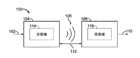
図1は、本発明の例示的な実施形態による、例示的なワイヤレス電力伝達システム100の機能ブロック図である。エネルギー伝達を可能にするための場105を生成するために、電源(図示せず)から、送信機104に入力電力102を提供することができる。受信機108は、場105に結合し、出力電力110に結合されたデバイス(図示せず)が蓄積または消費するための出力電力110を生成することができる。送信機104と受信機108の両方は互いに距離112だけ離間される。例示的な一実施形態では、送信機104および受信機108は、相互共振関係に従って構成される。受信機108の共振周波数および送信機104の共振周波数が、ほぼ同じか、または極めて近いとき、送信機104と受信機108との間の伝送損失は最小となる。したがって、コイルが極めて近い(たとえば、数mm)ことが必要な大型のコイルを必要とすることがある純粋に誘導性のソリューションとは対照的に、より長い距離にわたってワイヤレス電力伝達を可能にすることができる。したがって、共振誘導結合技法は、様々な距離にわたって、かつ様々な誘導コイル構成を用いて効率の改善および電力伝達を可能にし得る。
FIG. 1 is a functional block diagram of an exemplary wireless
受信機108は、送信機104によって生成されたエネルギー場105内に位置するときに、電力を受信することができる。場105は、送信機104によって出力されたエネルギーが受信機108によって取り込まれ得る領域に対応する。場合によっては、場105は、以下でさらに説明するように、送信機104の「近接場」に対応し得る。送信機104は、エネルギー伝送を出力するための送信アンテナ114を含む場合がある。さらに、受信機108は、エネルギー伝送からエネルギーを受信する、または取り込むための受信アンテナ118を含む。近接場は、送信アンテナ114から電力を最小限に放出する、送信アンテナ114内の電流および電荷から生じる強い反応場(reactive field)が存在する領域に対応し得る。場合によっては、近接場は、送信アンテナ114の約1波長(または1波長の数分の一)内にある領域に対応し得る。送信アンテナ114および受信アンテナ118は、それらに関連付けられる応用形態およびデバイスに応じてサイズを決定される。上記のように、効率的なエネルギー伝達は、電磁波のエネルギーの大部分を遠距離場に伝搬するのではなく、送信アンテナ114の場105のエネルギーの大部分を受信アンテナ118に結合することによって起こり得る。場105内に位置決めされるとき、送信アンテナ114と受信アンテナ118との間に、「結合モード」を発生させることができる。この結合が起こり得る、送信アンテナ114および受信アンテナ118の周りのエリアは、本明細書において結合モード領域と呼ばれる。
The
図2は、本発明の様々な例示的な実施形態による、図1のワイヤレス電力伝達システム100において使用され得る例示的な構成要素の機能ブロック図である。送信機204は、発振器222と、ドライバ回路224と、フィルタ/整合回路226とを含むことができる、送信回路206を含んでよい。発振器222は、周波数制御信号223に応答して調整され得る、468.75KHz、6.78MHz、または13.56MHzなどの所望の周波数で信号を生成するように構成され得る。発振器信号は、たとえば送信アンテナ214の共振周波数において送信アンテナ214を駆動するように構成されたドライバ回路224に与えられ得る。ドライバ回路224は、発振器222から方形波を受信し、正弦波を出力するように構成されたスイッチング増幅器とすることができる。たとえば、ドライバ回路224は、E級増幅器であってよい。また、フィルタ/整合回路226は、高調波または他の不要な周波数をフィルタ除去し、送信機204のインピーダンスを送信アンテナ214に整合させるために含まれる場合がある。送信アンテナ214を駆動した結果として、送信機204は、電子デバイスを充電または給電するのに十分なレベルで電力をワイヤレスで出力できる。一例として、提供される電力は、異なる電力要件を有する異なるデバイスを給電または充電するために、たとえば、300ミリワットから5ワット程度であり得る。より高いまたは低い電力レベルも提供できる。
FIG. 2 is a functional block diagram of exemplary components that may be used in the wireless
受信機208は、整合回路232と図2に示すバッテリー236を充電する、または受信機208に結合されたデバイス(図示せず)に電力を供給するためにAC電力入力からDC電力出力を生成するための整流器/スイッチング回路234とを含み得る受信回路210を含んでよい。整合回路232は、受信回路210のインピーダンスを受信アンテナ218に整合させるために含まれる場合がある。加えて、受信機208および送信機204は、別個の、または帯域外の通信チャネル219(たとえば、ブルートゥース、ZigBee、セルラーなど)上で通信してよい。代替的には、受信機208および送信機204は、ワイヤレス場205の特性を用いて帯域内シグナリングを介して通信することができる。
The
以下でより十分に説明するように、選択的に無効にできる関連する負荷(たとえば、バッテリー236)を最初に有することができる受信機208は、送信機204によって送信され、受信機208によって受信される電力の量が、バッテリー236を充電するのに適切であるかどうかを判断するように構成され得る。さらに、受信機208は、電力の量が適切であると判断すると、負荷(たとえば、バッテリー236)を有効にするように構成され得る。いくつかの実施形態では、受信機208は、バッテリー236を充電せずに、ワイヤレス電力伝達場から受信された電力を直接利用するように構成され得る。たとえば、近接場通信(NFC)または無線周波数識別デバイス(RFID)などの通信デバイスは、ワイヤレス電力伝達場から電力を受信し、ワイヤレス電力伝達場と相互作用することによって通信し、かつ/または送信機204もしくは他のデバイスと通信するために受信電力を利用するように構成され得る。
As will be described more fully below, a
図3は、本発明の例示的な実施形態による、送信アンテナまたは受信アンテナ352を含む、図2の送信回路206または受信回路210の一部分の概略図である。図3に示すように、以下で説明するものを含む例示的な実施形態において使用される送信回路または受信回路350は、アンテナ352を含むことができる。アンテナ352は、「ループ」アンテナ352と呼ばれるか、または「ループ」アンテナ352として構成される場合もある。また、アンテナ352は、本明細書では、「磁気」アンテナもしくは誘導コイルと呼ばれるか、または「磁気」アンテナもしくは誘導コイルとして構成される場合もある。「アンテナ」という用語は、一般に、別の「アンテナ」に結合するためのエネルギーをワイヤレスで出力するか、または受け取ることができる構成要素を指す。アンテナは、電力をワイヤレスで出力するか、または受け取るように構成されるタイプのコイルと呼ばれてもよい。本明細書で使用する場合、アンテナ352は、電力をワイヤレスで出力および/または受信するように構成されるタイプの「電力伝達構成要素」の一例である。アンテナ352は、空芯、またはフェライトコア(図示せず)などの物理的コアを含むように構成され得る。空芯ループアンテナは、コアの近くに配置された外部の物理デバイスに対してより耐性があり得る。さらに、空芯ループアンテナ352により、コアエリア内に他の構成要素を配置することが可能になる。加えて、空芯ループにより、送信アンテナ214(図2)の結合モード領域がより強力な場合がある送信アンテナ214(図2)の平面内に、受信アンテナ218(図2)をより容易に配置することが可能になる場合がある。
FIG. 3 is a schematic diagram of a portion of the transmit
上述のように、送信機104と受信機108との間のエネルギーの効率的な伝達は、送信機104と受信機108との間に整合した共振またはほぼ整合した共振が生じている間に起こり得る。しかしながら、送信機104と受信機108との間の共振が整合しないときであっても、効率に影響が及ぶ場合があるものの、エネルギーを伝達することができる。エネルギーの伝達は、送信アンテナ214コイルの場105からのエネルギーを、近傍にある受信アンテナ218に結合することによって起こり、この場105は、送信アンテナ214からのエネルギーを自由空間に伝播させる代わりに確立される。
As described above, efficient transfer of energy between the
ループアンテナまたは磁気アンテナの共振周波数は、インダクタンスおよびキャパシタンスに基づく。インダクタンスは単にアンテナ352によって生成されたインダクタンスとすることができるのに対して、キャパシタンスは、所望の共振周波数で共振構造を作り出すために、アンテナのインダクタンスに加えられる場合がある。非限定的な例として、共振周波数で信号358を選択する共振回路を生成するために、送信回路または受信回路350にキャパシタ354およびキャパシタ356を加えてよい。したがって、より大きい直径のアンテナでは、共振を持続させるのに必要なキャパシタンスのサイズは、ループの直径またはインダクタンスが大きくなるにつれて小さくなる場合がある。さらに、アンテナの直径が大きくなるにつれて、近接場の効率的なエネルギー伝達面積が増加する場合がある。他の構成要素を用いて形成される他の共振回路も可能である。別の非限定的な例として、アンテナ352の2つの端子間に並列にキャパシタを配置することができる。送信アンテナの場合、アンテナ352の共振周波数に実質的に対応する周波数を有する信号358を、アンテナ352への入力とすることができる。
The resonant frequency of the loop antenna or magnetic antenna is based on inductance and capacitance. The inductance may simply be the inductance generated by the
一実施形態では、送信機104は、送信アンテナ114の共振周波数に対応する周波数を有する時変磁場を出力するように構成され得る。受信機が場105内にあるとき、時変磁場は、受信アンテナ118内に電流を誘導することができる。上記のように、受信アンテナ118が送信アンテナ114の周波数で共振するように構成される場合には、エネルギーを効率的に伝達することができる。受信アンテナ118内に誘導されたAC信号を上記のように整流して、負荷を充電するか、または負荷に電力を供給するために与えられ得るDC信号を生成することができる。
In one embodiment,
図4は、本発明の例示的な実施形態による、図1のワイヤレス電力伝達システムにおいて使用され得る送信機404の機能ブロック図である。送信機404は、送信回路406および送信アンテナ414を含むことができる。送信アンテナ414は、図3に示すアンテナ352とすることができる。送信回路406は、発振信号を与えることによって、送信アンテナ414にRF電力を与えることができ、その信号の結果として、送信アンテナ414の周りにエネルギー(たとえば、磁束)が生成される。送信機404は、任意の適切な周波数で動作することができる。例として、送信機404は、6.78MHzのISM帯域で動作することができる。
FIG. 4 is a functional block diagram of a
送信回路406は、送信回路406のインピーダンス(たとえば、50オーム)を送信アンテナ414に整合させるための固定インピーダンス整合回路409と、高調波放射を、受信機108(図1)に結合されたデバイスの自己ジャミングを防ぐレベルまで低減するように構成されたローパスフィルタ(LPF)408とを含むことができる。他の例示的な実施形態は、それに限定されるわけではなく、異なるフィルタトポロジを含み、またノッチフィルタを含み得るが、ノッチフィルタは特定の周波数を減衰させる一方で、他の周波数を通過させ、アンテナ414への出力電力、またはドライバ回路424によって引き出されるDC電流など、測定可能な送電メトリックに基づいて変化し得る、適応インピーダンス整合を含んでよい。送信回路406は、発振器423によって決定されるRF信号を駆動するように構成されたドライバ回路424をさらに含む。送信回路406は、個別のデバイスもしくは回路から構成されても、または代わりに、一体型アセンブリから構成されてもよい。送信アンテナ414から出力される例示的なRF電力は、2.5ワット程度とすることができる。
The transmit
送信回路406は、隣接するデバイスに取り付けられた受信機を介して隣接するデバイスと対話するための通信プロトコルを実装するように特定の受信機の送信位相(またはデューティサイクル)の間に発振器423を選択的に有効にするための、発振器423の周波数または位相を調整するための、かつ出力電力レベルを調整するためのコントローラ415をさらに含んでよい。コントローラ415は、本明細書においてプロセッサ415と呼ばれる場合があることに留意されたい。発振器位相および送信経路内の関連する回路の調整により、特に、ある周波数から別の周波数に移行する際の帯域外放射の低減が可能になり得る。
The transmit
送信回路406は、送信アンテナ414によって生成された近接場の近傍において作動中受信機の存否を検出するための負荷感知回路416をさらに含むことができる。例として、負荷感知回路416はドライバ回路424に流れる電流を監視し、以下でさらに説明するように、その電流は、送信アンテナ414によって生成された場の近傍における作動中受信機の存否によって影響を及ぼされる場合がある。ドライバ回路424上の負荷に対する変化の検出は、エネルギーを伝送するために発振器423を有効にすべきかどうか、および作動中受信機と通信すべきかどうかを判断する際に使用するためにコントローラ415によって監視される。以下でさらに十分に説明するように、ドライバ回路424において測定される電流は、送信機404のワイヤレス電力伝達領域内に無効なデバイスが位置決めされたかどうかを判断するために用いられ得る。
Transmit
送信アンテナ414は、リッツ線を用いて、または抵抗損を低く保つために選択された厚み、幅、および金属のタイプを有するアンテナストリップとして実装され得る。一実装形態では、送信アンテナ414は通常、テーブル、マット、ランプ、または他の可搬性の低い構成などの、より大きい構造と関連付けて構成され得る。したがって、送信アンテナ414は通常、その実用的な寸法のため「巻く」必要がない場合がある。送信アンテナ414の例示的な実装形態は、「電気的に小型」(すなわち、波長の数分の一)とすることができ、共振周波数を規定するためにキャパシタを使用することによって、より低い使用可能な周波数で共振するように同調することができる。
Transmit
送信機404は、送信機404に関連し得る受信機デバイスの所在および状態に関する情報を収集および追跡してよい。したがって、送信回路406は、(本明細書ではプロセッサとも呼ばれる)コントローラ415に接続される、存在検出器480、密閉型検出器460、またはこれらの組合せを含んでよい。コントローラ415は、存在検出器480および密閉型検出器460からの存在信号に応答してドライバ回路424によって送出される電力量を調整してよい。送信機404は、たとえば、ビル内にある従来のAC電力を変換するためのAC-DCコンバータ(図示せず)、従来のDC電源を送信機404に適した電圧に変換するためのDC-DCコンバータ(図示せず)などのいくつかの電源を介して、または従来のDC電源(図示せず)から直接電力を受信してよい。
The
非限定的な例として、存在検出器480は、送信機404のカバー領域に挿入される、充電されるべきデバイスの最初の存在を感知するために利用される運動検出器であってよい。検出後に、送信機404をオンにすることができ、デバイスによって受信されたRF電力を用いて、所定の方法でRxデバイス上のスイッチを切り替えることができ、それにより、結果として送信機404の駆動点インピーダンスが変化する。
As a non-limiting example,
別の非限定的な例として、存在検出器480は、たとえば、赤外線検出手段、運動検出手段、または他の適切な手段によって人を検出することが可能な検出器であってよい。いくつかの例示的な実施形態では、送信アンテナ414が特定の周波数で送信することができる電力量を制限する規制が存在してよい。場合によっては、これらの規制は、人を電磁放射から守ることを意図されている。しかしながら、送信アンテナ414が、たとえば、ガレージ、工場の作業場、店舗などの、人が占有しない、または人が占有する頻度が低いエリアに配置される環境が存在する場合もある。これらの環境に人がいない場合、通常の電力制限規制よりも高く、送信アンテナ414の電力出力を増加させることが許容可能な場合もある。言い換えれば、コントローラ415は、人の存在に応答して、送信アンテナ414の電力出力を規制レベル以下に調整し、人が送信アンテナ414の電磁場による規制距離の外側にいるとき、送信アンテナ414の電力出力を、規制レベルを超えるレベルに調整することができる。
As another non-limiting example,
非限定的な例として、密閉型検出器460(本明細書では、密閉型コンパートメント検出器または密閉型空間検出器と呼ばれることもある)は、包囲体が閉状態または開状態であるときを判定するための感知スイッチなどのデバイスであってよい。送信機が閉状態の包囲体内にあるとき、送信機の電力レベルを増加させてよい。 As a non-limiting example, a sealed detector 460 (sometimes referred to herein as a sealed compartment detector or a sealed spatial detector) determines when the enclosure is closed or open. It may be a device such as a sensing switch for When the transmitter is in a closed enclosure, the transmitter power level may be increased.
例示的な実施形態では、送信機404がいつまでもオンのままではない方法を使用してよい。この場合、送信機404は、ユーザが決定した時間の経過後にシャットオフするようにプログラムされ得る。この特徴は、送信機404の周囲のワイヤレスデバイスが十分充電された後、送信機404、特にドライバ回路424が長い間動作するのを防ぐ。このイベントは、リピータまたは受信アンテナ218のいずれかから送られた、デバイスが十分に充電されたという信号を検出するための回路の故障に起因する場合もある。送信機404の周囲に別のデバイスが配置されている場合に、送信機404が自動的にシャットダウンすることを防止するために、送信機404の自動シャットオフ機能は、その周囲で動作が検出されない定められた期間が経過した後にだけ、アクティブ化されてよい。ユーザは、非活動時間間隔を決定し、その時間間隔を所望により変更することができる場合がある。非限定的な例として、この時間間隔は、特定のタイプのワイヤレスデバイスが最初に完全に放電したという仮定の下に、そのデバイスを完全に充電するのに必要な時間間隔よりも長くてよい。
In an exemplary embodiment, a method may be used in which
図5は、本発明の例示的な実施形態による、図1のワイヤレス電力伝達システムにおいて使用され得る受信機508の機能ブロック図である。受信機508は、受信アンテナ518を含む場合がある受信回路510を含む。受信機508は、それに受信電力を供給するための充電可能デバイス550にさらに結合する。受信機508は、充電可能デバイス550の外部にあるものとして示されているが、充電可能デバイス550に統合されてもよいことに留意されたい。エネルギーは、受信アンテナ518にワイヤレスで伝搬され、その後、受信回路510の残りの部分を通して充電可能デバイス550に結合される場合がある。例として、充電可能デバイスには、携帯電話、ポータブル音楽プレーヤ、ラップトップコンピュータ、タブレットコンピュータ、コンピュータ周辺デバイス、通信デバイス(たとえば、ブルートゥースデバイス)、デジタルカメラ、補聴器(および他の医療用デバイス)などのデバイスが含まれ得る。
FIG. 5 is a functional block diagram of a
受信アンテナ518は、送信アンテナ414(図4)と同じ周波数において、または規定された周波数範囲内で共振するように同調させることができる。受信アンテナ518は、送信アンテナ414と同じような寸法にすることができるか、または関連する充電可能デバイス550の寸法に基づいて異なるサイズにすることができる。例として、充電可能デバイス550は、送信アンテナ414の直径または長さよりも小さい直径寸法または長さ寸法を有するポータブル電子デバイスとすることができる。そのような例では、受信アンテナ518は、同調キャパシタ(図示せず)のキャパシタンス値を低減させ、受信コイルのインピーダンスを増加させるために多巻きコイルとして実装され得る。例として、受信アンテナ518は、アンテナ径を最大化し、受信アンテナ518のループ巻き(すなわち、巻線)数を少なくし、巻線間キャパシタンスを下げるために、充電可能デバイス550の実質的な外周の回りに配置され得る。
The receive
受信回路510は、受信アンテナ518に対するインピーダンス整合をもたらすことができる。受信回路510は、受け取られたRFエネルギー源を充電可能デバイス550が使用するための充電電力に変換するための電力変換回路506を含む。電力変換回路506は、RF-DC変換器520を含み、またDC-DC変換器522を含んでもよい。RF-DC変換器520は、受信アンテナ518において受信されたRFエネルギー信号を、Vrectによって表される出力電圧を有する非交流電力に整流する。DC-DC変換器522(または他の電力調整器)は、整流されたRFエネルギー信号を、VoutおよびIoutによって表される出力電圧および出力電流を有する、充電可能デバイス550に適合するエネルギーポテンシャル(たとえば、電圧)に変換する。部分的および完全な整流器、調整器、ブリッジ、ダブラ、ならびにリニア変換器およびスイッチング変換器を含む、様々なRF-DC変換器が企図される。
The receiving
受信回路510は、受信アンテナ518を電力変換回路506に接続するか、または代替的には電力変換回路506を切断するためのスイッチング回路512をさらに含むことができる。電力変換回路506から受信アンテナ518を切断することにより、充電可能デバイス550の充電を中断するだけでなく、送信機404(図2)から「見える」ような「負荷」も変更する。
The receiving
上記で開示したように、送信機404は、送信機ドライバ回路424に供給されるバイアス電流の変動を検出することができる負荷感知回路416を含む。したがって、送信機404は、受信機が送信機の近接場内に存在するときを判断するための機構を有する。
As disclosed above, the
複数の受信機508が送信機の近接場内に存在するとき、他の受信機がより効率的に送信機に結合できるようにするために、1つまたは複数の受信機の装荷および除荷を時間多重化することが望ましい場合がある。受信機508はまた、他の近くの受信機への結合を解消するか、または近くの送信機への装荷を低減させるためにクローキングされ得る。受信機のこの「除荷」は、本明細書では「クローキング」とも呼ばれる。さらに、受信機508によって制御され送信機404によって検出される、除荷と装荷との間のこのスイッチングは、以下でより十分に説明するように、受信機508から送信機404への通信機構を実現することができる。加えて、受信機508から送信機404にメッセージを送ることを可能にするプロトコルが、このスイッチングに関連付けられ得る。例として、スイッチング速度は、100μ秒程度であってよい。
When
例示的な一実施形態では、送信機404と受信機508との間の通信は、従来の双方向通信(すなわち、結合場を使用する帯域内シグナリング)ではなく、デバイス感知および充電制御機構を指す。言い換えれば、送信機404は、エネルギーが近接場で利用可能であるかどうかを調整するために送信信号のオン/オフキーイングを使用してよい。受信機は、これらのエネルギー変化を送信機404からのメッセージとして解釈してよい。受信機側から、受信機508は、場から受け入れている電力量を調整するために受信アンテナ518の同調および離調を用いることができる。場合によっては、同調および離調は、スイッチング回路512を介して実現され得る。送信機404は、場からの使用される電力のこの差を検出し、これらの変化を受信機508からのメッセージとして解釈してよい。送信電力の変調および負荷挙動の他の形態を利用してよいことに留意されたい。
In an exemplary embodiment, communication between
受信回路510は、送信機から受信機への情報シグナリングに対応し得る、受信エネルギーの変動を識別するために使用される、シグナリング検出器/ビーコン回路514をさらに含んでよい。さらに、シグナリング/ビーコン回路514は、低減されたRF信号エネルギー(すなわち、ビーコン信号)の送信を検出し、かつ低減されたRF信号エネルギーを公称電力に整流し、受信回路510内の電力を供給されていない回路または電力が枯渇した回路のいずれかを呼び起こして受信回路510をワイヤレス充電が可能なように構成するために使用されてもよい。
The receiving
受信回路510は、本明細書で説明するスイッチング回路512の制御を含む、本明細書で説明する受信機508のプロセスを調整するためのプロセッサ516をさらに含む。また、受信機508のクローキングは、充電電力を充電可能デバイス550に提供する外部の有線充電ソース(たとえば、壁コンセント/USB電力)の検出を含む他のイベントが発生したときにも起こる可能性がある。プロセッサ516は、受信機のクローキングを制御するのに加えて、ビーコン回路514を監視してビーコン状態を判断し、送信機404から送信されたメッセージを抽出してもよい。プロセッサ516はまた、性能の改善のためにDC-DC変換器522を調整してもよい。
The
複数の送信機が受信機の帯域外通信範囲内にあるとき、受信機にワイヤレス電力を伝達するのに最も適した送信機との通信を確立することが重要である。送信機と受信機との間の帯域外通信は、後述のようにワイヤレス電力伝達場から区別された通信チャネルを介して実行され得る。図6は、複数の送信機の近傍に受信機が位置する場合を示す機能ブロック図である。図示のように、受信機208は、場205を介して送信機204からワイヤレス電力を受信するように位置する。しかしながら、受信機208は、送信機204、204a、および204bとの帯域外通信チャネル219を確立することが可能である。したがって、受信機208が送信機204aまたは204bとのチャネル219を確立する場合、電力伝達に関連する後続通信はすべて不適切なものとなる。この状況は、本明細書では誤接続と呼ばれ得る。
When multiple transmitters are within the receiver's out-of-band communication range, it is important to establish communication with the most suitable transmitter to transfer wireless power to the receiver. Out-of-band communication between the transmitter and receiver may be performed via a communication channel that is distinct from the wireless power transfer field, as described below. FIG. 6 is a functional block diagram showing a case where a receiver is located near a plurality of transmitters. As shown, the
図7は、図4の送信回路406、および図5の受信回路510を内蔵し得る帯域外通信が可能なワイヤレス充電システム700のブロック図である。ワイヤレス充電システム700は、ワイヤレス充電器702および充電可能デバイス704を含み得る。ワイヤレス充電器702は、ワイヤレス電力送信機710および帯域外通信トランシーバ720を含み得る。一実施形態において、ワイヤレス電力送信機710は、図4の送信回路406と類似していてもよく、かつ/またはそれと同じ機能を含み得る。充電可能デバイス704は、図5の充電可能デバイス550と類似していてもよく、ワイヤレス電力受信機715および帯域外通信トランシーバ725をさらに含み得る。一実施形態において、ワイヤレス電力受信機715は、図5の受信回路510と類似していてもよく、かつ/またはそれと同じ機能を含み得る。
FIG. 7 is a block diagram of a
ワイヤレス電力送信機710は、送信アンテナ714に結合され得る。送信アンテナ714は、図4の送信コイル414に類似していてもよい。同様に、ワイヤレス電力受信機715は、受信コイル718に結合され得る。受信コイル718は、図5の受信コイル518に類似していてもよい。一実施形態において、ワイヤレス電力送信機710は、充電可能デバイス704を充電するためにワイヤレス電力受信機715に電力をワイヤレスで送信するように構成され得る。
帯域外通信トランシーバ720はアンテナ724に結合されてよく、帯域外通信トランシーバ725はアンテナ728に結合され得る。一実施形態において、充電可能デバイス704がそのバッテリーまたは類似のデバイスを充電するために、ワイヤレス充電器702から電力をワイヤレスで受信することができるように、ワイヤレス充電器702と充電可能デバイス704との間の接続を確立するために、アンテナ724および728を介して、帯域外通信トランシーバ720および725が使用され得る。帯域外通信は、任意のワイヤレス通信プロトコル(たとえば、プロプライエタリ通信プロトコル、IEEEのような標準化団体によって確立される通信プロトコル)の使用を介して実施され得る。たとえば、IrDA、Wireless USB、Z-Wave、ZigBeeなどが使用され得る。
Out-of-
本明細書で開示する解決技法の理解を深めるために、帯域外通信チャネルを確立するための例示的な方法を理解することは有益である。図8は、ワイヤレス充電器702および充電可能デバイス704など、ワイヤレス充電器と充電可能デバイスとの間の、ワイヤレス充電器と充電可能デバイスとの間の接続を確立するための通信のタイミング/信号フロー図である。ワイヤレス充電器702は、電力パルス802(たとえば、ビーコン信号)を送信することができ、電力パルス802は、充電可能デバイス704のような充電可能デバイスに、充電可能デバイスを充電するために電力を供給するのに使用され得る。ワイヤレス充電器702は、充電可能デバイスを検出するために、電力パルス802を送信することができる。図8に示すように、電力パルス802は送信されても、充電可能デバイスは電力パルス802の範囲内にはない。ワイヤレス充電器702は、別の電力パルス804を送信する前に、ある程度の時間待機することができる。たとえば、ワイヤレス充電器702は、パルス間で1秒間待機することができる。電力パルス802および/または804を送信すると、ワイヤレス充電器702は、通常の接続確立手順を開始することができる。図8に示すように、電力パルス804は、送信され、充電可能デバイス704の範囲内にある。
To better understand the solution techniques disclosed herein, it is beneficial to understand an exemplary method for establishing an out-of-band communication channel. FIG. 8 illustrates communication timing / signal flow between a wireless charger and a rechargeable device, such as
ひとたびワイヤレス充電器702が電力パルス804における負荷を検出すると、ワイヤレス充電器702は、充電可能デバイス704のようなデバイスからのブロードキャストについてのスキャンを開始する。このようにして、ワイヤレス充電器702は、ひとたびそれが電力パルスにおける負荷を検出すると、ブロードキャストについてのスキャンのみによって電力を節約することができる。一実施形態において、電力パルス804は、充電可能デバイス704にブロードキャストを生成させる(たとえば、充電可能デバイス704のプロセッサはブロードキャストを生成することができる)。一例として、ブロードキャスト806は、ブルートゥース低エネルギーチャネルを介して送信されるメッセージであり得る。充電可能デバイス704は、予定受信者としてワイヤレス充電器702へブロードキャスト806を送信することができる。(図8に示すように)ブロードキャスト806がワイヤレス充電器702に到達しない場合、充電可能デバイス704は、別のブロードキャスト808を生成し、送信することができる。たとえば、充電可能デバイス704は、別のブロードキャスト808を送る前に20ms待機することができる。接続が、たとえば10秒間、ある時間フレーム以内に確立されない場合、充電可能デバイス704は、接続可能なモードを出て、開始し得た任意の充電を停止することができる。このようにして、充電可能デバイス704は、ひとたびそれがワイヤレス充電器702から電力パルス802および/または804を受信すると、ブロードキャスト806および/または808を生成し、送信することのみによって、電力を節約することができる。
Once the
誤接続が生じ得る多数の状況があることに留意されたい。たとえば、充電可能デバイス704以外の別のデバイスまたはワイヤレス充電器702の近傍にあるオブジェクトが、ワイヤレス充電器702に負荷を検出させ、ブロードキャストについてのスキャンを開始させることがある。別の例として、いくつかの充電器は、電力パルス802および804のタイミングとは無関係に、ブロードキャストについて継続的にスキャンし得る。また別の例として、いくつかの充電可能デバイスは、電力パルス802および804のタイミングとは無関係に、継続的にブロードキャストし得る。また別の例として、ワイヤレス充電器は、通信の初期化を先取りする形で、電力パルスを発信した充電器の前にブロードキャストに応答することがある。したがって、これらの状況および他の状況では、ワイヤレス充電器702は、効果的な充電領域の外に位置する充電可能デバイスとの通信をその意図を外れて確立し、誤接続が生じることがある。
Note that there are many situations where misconnections can occur. For example, another device other than rechargeable device 704 or an object in the vicinity of
ひとたびワイヤレス充電器702がブロードキャスト808を受信すると、ワイヤレス充電器は、接続要求812を充電可能デバイス704に送信することができる。充電可能デバイス704が接続要求812を受け入れた場合、ワイヤレス充電器702と充電可能デバイス704との間で接続814が確立される。
Once the
図8に示した接続プロセスの間、ワイヤレス充電器702が、充電可能デバイス704を充電するために、たとえば電力パルス802および/または804を介して、電力810を送信し続けることができることに留意されたい。いくつかの態様では、充電可能デバイス704は、充電器電力供給モードの中にあり、ワイヤレス充電器702との接続を確立するために、電力810によって、充電可能デバイス704はアクティブのままとすることができる。接続を確立することができない、充電可能デバイス704が現在自己電力供給モードである、および/またはその他、充電可能デバイス704がワイヤレス充電器702から送信される電力を必要としないとワイヤレス充電器702が判断すると、ワイヤレス充電器702は、電力810を送信するのを停止することができる。
It is noted that during the connection process shown in FIG. 8, the
接続が任意のポイントで失われた場合、充電可能デバイス704は、ワイヤレス充電器702との再接続を試みることができる。代替として、充電可能デバイス704は、それがワイヤレス充電器702から別の電力パルス802および/または804を受信するまで待機することができる。
If the connection is lost at any point, the rechargeable device 704 can attempt to reconnect with the
本明細書で開示するいくつかの技法は、送信機と受信機との間で帯域外通信チャネルが不適切に確立(たとえば、誤接続)されていないかを確認するために使用され得る。これらの技法は、本明細書では解決技法と呼ばれる。これらの解決技法のいくつかは、最適な送信機と受信機との間で帯域外通信チャネルが確立されていることを必ずしも保証するとは限らない。代わりに、いくつかの技法は、確立された通信チャネルの妥当性を推理してサポートするか、または弱める傾向がある。したがって、これらの解決技法のうちの1つまたは複数が、ワイヤレス電力伝達システムにおいて使用され得る。さらに、これらの解決技法のアウトプットは、その特定の技法のしきい値と比較され、および/または本明細書で開示する他の技法と組み合わされることがある。これらの技法のアウトプットが重み付けされ、確率的またはあいまい論理タイプモデルで使用されて、誤接続があるかどうかどうか、また帯域外通信が再接続を試みるべきかどうかが評価され得る。 Some techniques disclosed herein may be used to verify that an out-of-band communication channel is not improperly established (eg, misconnected) between a transmitter and a receiver. These techniques are referred to herein as resolution techniques. Some of these solutions do not always guarantee that an out-of-band communication channel is established between the optimal transmitter and receiver. Instead, some techniques tend to infer and support or weaken the validity of established communication channels. Accordingly, one or more of these solution techniques may be used in a wireless power transfer system. Further, the output of these solution techniques may be compared to the threshold values of that particular technique and / or combined with other techniques disclosed herein. The output of these techniques can be weighted and used in a probabilistic or ambiguous logic type model to evaluate whether there is a misconnection and whether out-of-band communication should attempt to reconnect.
解決技法は、コントローラ(たとえば、図4のコントローラ415、図5のプロセッサ516、図7のコントローラ730、735)によって実行され得る。一実施形態では、解決技法は、送信機側のコントローラによって、帯域外通信チャネルを介して送信された受信機側の測定値により評価され得る。別の実施形態では、解決技法は、送信機側または受信機側のいずれかによって、帯域外通信チャネルを介して送信機(または受信機)に送信され得られたアウトプットにより評価され得る。さらに、誤接続を識別すると、帯域外通信チャネルを中断する前に、ローカルコントローラはリモートコントローラに誤接続を通知し得る。
The solution technique may be performed by a controller (eg,
第1の解決技法では、送信機の動作を受信機の動作に関係付けるために時間一致が使用される。すなわち、送信機(たとえば、ワイヤレス充電器702)の起動から受信機(たとえば、充電可能デバイス704)の通信までの間の経過時間が測定される。たとえば、ワイヤレス充電器702は、電力パルス804を送信するとタイマーを開始し得る。ワイヤレス充電器702が充電可能デバイス704からブロードキャスト808を受信する時間に近いほど、ワイヤレス充電器と充電可能デバイスとの相関は良好であるので、誤接続が起こる可能性は低くなる。この技法は、充電可能デバイス704が電力パルス804を受信してから、それぞれのブロードキャスト806/808を送信するまでに経過した時間(たとえば、「スタートアップ」時間)の量に関連する情報をブロードキャスト808で送信することをさらに含むことができる。ワイヤレス充電器702は、スタートアップ時間に関連する情報を含むブロードキャストを受信すると、相関をさらに改善するために、開始されたタイマーからこの時間を差し引くことができる。たとえば、電力パルス804が時間t=0で送信され、80msのスタートアップ時間を示すブロードキャスト808が時間t=90msで受信された場合、負でない小さい時間差(10ms)により、誤接続の可能性は低下する。一方、示されたスタートアップ時間が120msであった場合、充電可能デバイス704は別のワイヤレス充電器の電力パルスに応答してブロードキャスト808を送信している可能性が高い。複数のワイヤレス充電器が(たとえば、スイッチによって)同時に起動することがあるので、この技法はさらに、各ワイヤレス充電が電力パルスを送信する前にランダムな時間量だけ遅れることを含み得る。そのため、この技法の相関効果を改善するために、個々のワイヤレス充電器から充電可能デバイスによって受信される電力パルスのタイミングは離間され得る。
In the first solution technique, time matching is used to relate the operation of the transmitter to the operation of the receiver. That is, the elapsed time from activation of a transmitter (eg, wireless charger 702) to communication of a receiver (eg, rechargeable device 704) is measured. For example, the
第2の解決技法では、ワイヤレス電力システムに対し、それが予想される挙動を示すかどうかをチェックするために受動テストが適用される。「受動」テストは通常、ワイヤレス電力システムの正常な動作を妨害しないテストを指す。正しく挙動しないシステムは、誤接続を有する可能性が高い。本明細書で説明する受動テストのうちの1つまたは複数により誤接続が検出された場合、デバイスがワイヤレス電力伝達を再び有効にするために接続を再確立しなければならない状態またはヌルリセットなど、ワイヤレス充電回復ルーチンを開始するために誤接続状態がトリガされ得る。この技法によって企図される第1の予想される挙動は、(たとえば、整流器/スイッチング回路234またはRF-DC変換器520の出力で測定される)整流器出力電圧Vregと(たとえば、送信アンテナ214、414または714を通して測定される)送信機ループ電流Itxとの間の関係を伴う。正常に動作するシステムでは、VregはItxの後を追う。システムが予想外に飽和状態になった(たとえば、Itxが、Vregの対応する増加を伴わずに最大値に達した)場合、誤接続がある可能性が高い。このシナリオでは、受信機は、受信機が電力を受信している送信機ではなく、帯域外通信チャネルを確立した相手である送信機に追加電力を要求している可能性が高い。この技法によって企図される第2の予想される挙動は、受信機電力と送信機電力との関係を伴う。正常に動作するシステムでは、受信機電力が増加するとき、送信機電力も増加するはずである。送信機電力が増加しない場合、誤接続がある可能性が高い。この技法によって企図される第3の予想される挙動は、受信機がItxの変更を要求した後のVregの監視を伴う。正常に動作するシステムでは、受信機は、たとえば負荷または距離の変化に適応するために、Itxの変更を周期的に要求する。そのような要求の結果、送信機がそのループ電流を変更し、受信機が整流器出力電圧の変化を観測していない場合、誤接続がある可能性が高い。上述の様々なパラメータ(たとえば、Vreg、Itx、飽和状態、受信機電力、送信機電力)が、帯域外通信チャネルを介して送信機と受信機との間で通信され得る。このようにして、送信機または受信機のいずれかを使用して、誤接続の可能性を評価することができる。
In the second solution technique, a passive test is applied to the wireless power system to check if it exhibits the expected behavior. A “passive” test usually refers to a test that does not interfere with the normal operation of the wireless power system. Systems that do not behave correctly are likely to have misconnections. If a misconnection is detected by one or more of the passive tests described herein, such as a condition where the device must reestablish a connection to re-enable wireless power transfer, or a null reset, etc. A misconnection condition may be triggered to initiate a wireless charge recovery routine. The first expected behavior contemplated by this technique is the rectifier output voltage Vreg (e.g., measured at the output of rectifier /
第3の解決技法では、ワイヤレス電力システムに対し、それが予想される挙動に応答しているかどうかをチェックするために能動テストが適用される。上述の受動テストとは対照的に、「能動」テストは通常、ワイヤレス電力システムの正常な動作を妨害し得るテストを指す。正しく応答しないシステムは、誤接続を有する可能性が高い。上述の能動テストのうちの1つまたは複数により誤接続が検出された場合、ワイヤレス充電回復ルーチンを開始するために誤接続状態がトリガされ得る。例示的なテストでは、送信機はItxにおける過渡事象(transient)をもたらす。応答して、Vregは同様に増加するはずである。受信機がVregの変化を観測していない場合、誤接続がある可能性が高い。このテストの1つの変形は、送信機がシステムに過渡事象をもたらすタイミングをランダム化することを伴う。そのようなランダム化は、2つの過渡事象が同時に生じる可能性を低下させるのに役立つ(たとえば、送信機はItxを増加させるが、Vregの増加をもたらす負荷の独立した、対応する減少がある)。さらに別のテストでは、送信機は電力を送信するのを停止して、Itxをゼロに落とし、受信機との帯域外通信チャネルがまだアクティブであるかどうかをチェックすることができる。チャネルがアクティブなままである場合、受信機の帯域外通信トランシーバがワイヤレス電力をもはや受信していないことに応答して、非アクティブ化するように構成されていると仮定すると、誤接続が証明される。本明細書で開示する他の解決技法の多くとは異なり、この最後の能動テストは、誤接続という最終判断をもたらすことに留意されたい。 In a third solution technique, an active test is applied to the wireless power system to check whether it is responding to expected behavior. In contrast to the passive test described above, an “active” test typically refers to a test that can interfere with the normal operation of the wireless power system. A system that does not respond correctly is likely to have a misconnection. If a misconnection is detected by one or more of the active tests described above, a misconnection condition may be triggered to initiate a wireless charge recovery routine. In an exemplary test, the transmitter results in a transient event (-transient) in I tx. In response, V reg should increase as well. If the receiver is not observing changes in V reg , there is a high probability of a misconnection. One variation of this test involves randomizing when the transmitter causes a transient event in the system. Such randomization helps reduce the likelihood of two transient events occurring simultaneously (e.g., the transmitter increases Itx , but there is an independent, corresponding decrease in load that results in an increase in Vreg. is there). In yet another test, the transmitter can stop transmitting power, drop Itx to zero, and check whether the out-of-band communication channel with the receiver is still active. If the channel remains active, assuming that the receiver's out-of-band communication transceiver is configured to deactivate in response to no longer receiving wireless power, a misconnection is proven. The Note that unlike many of the other solution techniques disclosed herein, this last active test results in a final determination of a misconnection.
第4の解決技法では、ワイヤレス充電器は、ある許容可能な確実性レベルで「存在するとわかっている」または「離れているとわかっている」充電可能デバイスの動的リストを維持することができる。「存在するとわかっている」リスト上の充電可能デバイスは、デフォルトでは接続されている一方、「離れているとわかっている」リスト上の充電可能デバイスは、デフォルトでは接続されていない。タイムアウト期間は、デバイスが「存在するとわかっている」または「離れているとわかっている」のいずれかである可能性の後続評価が出るまで、デバイスがいずれかのリストから除去される時間を制御し得る。タイムアウト期間は、特定のワイヤレス電力システムの予想される使用に応じて設定され得る(たとえば、自宅では20〜30分程度、または地下鉄の中では1〜5分程度)。これにより、充電可能デバイスが誤ったリストに置かれている状況からの回復が可能になる。デバイスを「存在するとわかっている」リスト上に置き得る事象の例には、正しい接続を確認する事象、たとえば、受動テスト、能動テスト、本明細書で開示する解決技法の何らかの組合せなどがある。デバイスを「離れているとわかっている」リスト上に置き得る事象の例には、誤接続を確認する事象、たとえば、受動テスト、能動テスト、本明細書で開示する解決技法の何らかの組合せ、(後述する)電力が送信されていないときに到着する新しい接続要求などがある。 In the fourth solution technique, the wireless charger can maintain a dynamic list of rechargeable devices that are “known to be present” or “known to be away” at some acceptable certainty level. . Chargeable devices on the “Known to exist” list are connected by default, while rechargeable devices on the “Knowed away” list are not connected by default. The timeout period controls how long a device is removed from either list until a subsequent evaluation of the likelihood that the device is either "known to exist" or "known to be away" Can do. The timeout period may be set depending on the anticipated use of a particular wireless power system (eg, on the order of 20-30 minutes at home or 1-5 minutes in the subway). This allows recovery from situations where rechargeable devices are on the wrong list. Examples of events that can place a device on a “known to exist” list include events that confirm the correct connection, such as passive testing, active testing, or some combination of the solution techniques disclosed herein. Examples of events that can place a device on a `` Knowed Away '' list include events that confirm misconnections, e.g., passive testing, active testing, any combination of solution techniques disclosed herein ( There is a new connection request that arrives when power is not being transmitted.
第5の解決技法は、充電可能デバイスが電力パルスの第1の受信を「認識している」ことを利用する。電力パルスの受信後に生じるメッセージング、たとえばブロードキャスト808では、充電可能デバイスは、それが帯域外通信リンクを確立する第1の試みであることを示すメッセージフラグを設定し得る。その結果、このフラグを含むメッセージを受信する任意のワイヤレス充電器は、この充電可能デバイスとの帯域外通信を確立することを試み得る。前述のように、ワイヤレス充電器が、電力パルスを送っていないのに、このフラグを含むメッセージを受信した場合、ワイヤレス充電器は、関連する充電可能デバイスを「離れているとわかっている」リスト上に置くことができる。同様に、ワイヤレス充電器がこのフラグを含むメッセージを受信し、関連する充電可能デバイスが「離れているとわかっている」リスト上にある場合、ワイヤレス充電器は、リストから充電可能デバイスを除去し、帯域外通信チャネルを確立することを試みることができる。
A fifth solution technique utilizes that the rechargeable device is “aware” of the first reception of the power pulse. In messaging that occurs after receipt of a power pulse, such as
第6の解決技法では、帯域外通信チャネルを介して充電可能デバイスとワイヤレス充電器との間で通信される情報が、誤接続を示すために使用され得る。たとえば、本発明のいくつかの実施形態では、充電可能デバイスは、充電可能デバイスに関連付けられ得る様々なパラメータを示す情報をワイヤレス充電器に送信し得る。たとえば、充電可能デバイスは、デバイスのタイプ(たとえば、タブレットデバイス、ヘッドセット、ラップトップ、携帯電話など)を示す情報、またはデバイスの最大電力定格(たとえば、0.5W、4.2W、11Wなど)を示す情報を送信し得る。ワイヤレス充電器は、オブジェクトがワイヤレス電力場に入ったときにインピーダンスの変化にさらされることになる。ワイヤレス充電器は、受信された情報に基づく予想されるインピーダンスの変化を、測定されたインピーダンスの変化と比較し得る。測定された変化が予想されたものに近い場合、誤接続がある可能性は低い。本明細書で説明する解決技法のいずれかと同様に、誤接続が識別されたとき、誤接続回復ルーチンが開始され得る。 In a sixth solution technique, information communicated between the chargeable device and the wireless charger via an out-of-band communication channel can be used to indicate a misconnection. For example, in some embodiments of the present invention, the rechargeable device may send information to the wireless charger indicating various parameters that may be associated with the rechargeable device. For example, a rechargeable device shows information indicating the type of device (e.g., tablet device, headset, laptop, mobile phone, etc.), or shows the maximum power rating of the device (e.g., 0.5W, 4.2W, 11W, etc.) Information can be sent. The wireless charger will be subject to impedance changes when the object enters the wireless power field. The wireless charger may compare the expected impedance change based on the received information with the measured impedance change. If the measured change is close to what is expected, there is a low probability of a misconnection. As with any of the solution techniques described herein, a misconnection recovery routine may be initiated when a misconnection is identified.
第7の解決技法では、ワイヤレス充電器の近くの領域内に置かれた新しいデバイスを検出するために近接センサーが使用され得る。そのような近接センサーはさらに、生物の存在を検出するために使用され得る。これらの近接センサーを含むワイヤレス充電器は、デバイスの検出から後続の新しい接続要求までの経過時間を評価し得る。第1の解決技法の場合のように、デバイス検出が新しい接続要求に近い時間に生じた場合、誤接続がある可能性は低い。 In a seventh solution technique, a proximity sensor can be used to detect new devices placed in the area near the wireless charger. Such proximity sensors can further be used to detect the presence of an organism. Wireless chargers that include these proximity sensors can evaluate the elapsed time from device detection to subsequent new connection requests. If device detection occurs at a time close to a new connection request, as in the first solution technique, it is unlikely that there is a misconnection.
第8の解決技法では、ワイヤレス充電器に対する充電可能デバイスの相対ロケーションが推定され得る。ロケーション情報により、適切な帯域外通信チャネルの確立が容易になる。ワイヤレス充電器に対する充電可能デバイスの相対ロケーションを推定する1つの方法は、三角測量と同様の技法を伴う。この方法では、ワイヤレス充電器に2つ以上のアンテナが含まれ得る。これらのアンテナと充電可能デバイスとの間で送信された信号に対して、信号強度および/または位相シフトが測定され得る。2つのアンテナの場合、充電可能デバイスのロケーションは、帯域外通信チャネルの範囲に基づく最大半径を有する2つの球形の円形交差部に沿ったどこかにあると推定され得る。この解決は、充電可能デバイスがワイヤレス充電器の場の中にあるのかを推定するのに適切であり得る。 In an eighth solution technique, the relative location of the rechargeable device with respect to the wireless charger may be estimated. Location information facilitates the establishment of an appropriate out-of-band communication channel. One method for estimating the relative location of a rechargeable device with respect to a wireless charger involves a technique similar to triangulation. In this manner, the wireless charger can include more than one antenna. Signal strength and / or phase shift may be measured for signals transmitted between these antennas and rechargeable devices. In the case of two antennas, the location of the rechargeable device can be estimated to be somewhere along two spherical circular intersections with a maximum radius based on the range of the out-of-band communication channel. This solution may be appropriate to estimate whether the rechargeable device is in the wireless charger field.
ロケーション推定の精度を高めるために、さらなるアンテナが追加され、対応する措置が講じられ得る。図9は、帯域外通信のための3つのアンテナをそれぞれ有する2つのコロケートされたワイヤレス充電器を示している。ワイヤレス充電器902の送信アンテナ904は、充電領域906内の効果的なワイヤレス電力送信を可能にする。同様に、ワイヤレス充電器912の送信アンテナ914は、充電領域916内の効果的なワイヤレス電力送信を可能にする。ワイヤレス充電器902は、3つの帯域外アンテナ908a、908b、および908cをさらに含む。アンテナ908a、908b、および908cの各々は、それぞれ効果的な通信範囲rA、rB、およびrCを有する。ワイヤレス充電器902およびワイヤレス充電器912が近接していることから、充電可能デバイス952がワイヤレス充電器912の充電領域916内およびワイヤレス充電器902の帯域外通信範囲内に位置し得る領域950が存在する。充電可能デバイス952がワイヤレス充電器902との通信を確立することを試みる場合、コントローラまたは他のデバイスは、帯域外アンテナ908a〜cの各々と充電可能デバイス952との間の距離を、充電可能デバイス952から発生しているブロードキャストまたは他の信号の信号強度測定値に少なくとも部分的に基づいて推定することができる。
To increase the accuracy of the location estimation, additional antennas can be added and corresponding measures can be taken. FIG. 9 shows two collocated wireless chargers each having three antennas for out-of-band communication. The transmit
充電可能デバイス952およびワイヤレス充電器は様々な形で互いに対して空間的に位置し得るが、ここでは、充電可能デバイス952およびワイヤレス充電器が実質的に同じ平面にあると仮定する。信号強度を推定距離に変換したか、または相関させた後、充電可能デバイス952のロケーションは次のように推定され得る。まず、充電領域に対する3つの帯域外アンテナのロケーションが知られており、座標ロケーション(R0x, R0y)、(R1x, R1y)、および(R2x, R2y)を割り当てられていると仮定する。帯域外アンテナの既知の位置を、関連する距離推定値D0、D1、およびD2と組合せ、充電可能デバイスの推定ロケーション(Tx, Ty)は、以下の式により計算され得る。
(Tx-R0x)2+(Ty-R0y)2=D02
(Tx-R1x)2+(Ty-R1y)2=D12
(Tx-R2x)2+(Ty-R2y)2=D22
Although
(T x -R0 x ) 2 + (T y -R0 y ) 2 = D0 2
(T x -R1 x ) 2 + (T y -R1 y ) 2 = D1 2
(T x -R2 x ) 2 + (T y -R2 y ) 2 = D2 2
充電可能デバイスの推定ロケーションがワイヤレス充電器の充電領域内にない場合、ワイヤレス充電器は充電可能デバイスに誤接続を通知することができる。ワイヤレス充電器と充電可能デバイスとの間のさらなる通信は終了し、接続は閉じることができる。充電可能デバイスの推定ロケーションがワイヤレス充電器の充電領域内にある場合、ワイヤレス充電器は随意に、継続的通信に不要な帯域外アンテナを無効にし、電力の伝達を開始する(または継続する)ことができる。他の実施形態では、帯域外アンテナ908a、908b、および908cは、充電可能デバイス952に信号を送信することができ、充電可能デバイス952は、帯域外アンテナの各々までの距離を推定し、必要に応じて、ワイヤレス充電器902に誤接続を通知することができることに留意されたい。
If the estimated location of the rechargeable device is not within the charging area of the wireless charger, the wireless charger can notify the rechargeable device of a misconnection. Further communication between the wireless charger and the rechargeable device is terminated and the connection can be closed. If the estimated location of the rechargeable device is within the charging area of the wireless charger, the wireless charger optionally disables out-of-band antennas that are not required for continuous communication and starts (or continues) power transmission Can do. In other embodiments, out-of-
引き続き図9を参照すると、図示された充電領域906、916は、全方向アンテナを示唆し得るが、指向性帯域外アンテナがワイヤレス充電器に組み込まれてもよい。指向性アンテナの主ローブまたは1次利得方向は、好ましくは充電エリアに向けられることになる。これは、充電可能デバイスのロケーション推定を改善するとともに、帯域外アンテナの重複する動作通信領域のサイズを縮小することによって、誤接続の可能性を低下させることができる。
With continued reference to FIG. 9, the illustrated charging
帯域外アンテナは、別個の信号強度/位相シフト測定回路を有する、またはmuxを介して回路を共有することができる。図10は、帯域外アンテナの間で共有される通信回路を有するワイヤレス充電器のブロック図である。帯域外アンテナ1002および1010はそれぞれmux1012に結合されており、mux1012はコントローラ1008によって制御され得る。muxは通信モジュール1004に結合される。通信モジュール1004は、帯域外アンテナ1002および1010のうちの少なくとも1つを介したデータの送信および受信を制御するためのトランシーバを含み得る。通信モジュールはさらに、コントローラ1008の制御下で、1つまたは複数のプロトコル(たとえば、ブルートゥース、ZigBee、セルラー、WiFi、NFCなど)に従って動作し得る。RSSI検出器1006は、通信モジュールに結合されており、2つの帯域外アンテナによって受信された信号の信号強度および/または位相を測定し、ロケーション推定のためにコントローラ1008に測定されたデータを提供することができる。RSSI検出器1006は信号強度を、コントローラ1008によって読み取られるデジタル値として、またはアナログデジタル変換器(図示せず)を介してコントローラ1008によってサンプリングされ得るアナログ電圧レベルとして提供することができる。
The out-of-band antenna can have a separate signal strength / phase shift measurement circuit or share the circuit via mux. FIG. 10 is a block diagram of a wireless charger having a communication circuit shared between out-of-band antennas. Out-of-
この共有回路構成により、通信モジュール1004またはRSSI検出器1006によってもたらされる任意の利得は共通であり、したがってロケーション推定に対し無視できる影響しか持たない可能性が高い。ただし、帯域外アンテナ1002および1010からmux1012への任意の信号経路または信号トレースは、好ましくは、ロケーション推定に使用される信号の信号強度または位相に影響を与え得る任意の歪みまたは信号完全性の問題を無効にするように整合するインピーダンスおよび長さとなる。この構成における各帯域外通信アンテナは通信回路を共有するので、ただ1つの帯域外アンテナが一度に送信または受信することがあり、ロケーション推定中にある程度の遅延がもたらされ得ることに留意されたい。
With this shared circuitry, any gain provided by the
図10に詳述するワイヤレス充電器の代替として、図11は、各帯域外アンテナのための独立した通信回路を有するワイヤレス充電器のブロック図である。この構成では、帯域外アンテナの各々は、所与の時間に送信または受信することができ、追加の構成要素および/またはコストという代償を払ってロケーション推定のための時間量を減らすことができる。図10とは対照的に、この構成はmuxを含まないが、代わりに上記のように並列の通信チャネルを含む。すなわち、帯域外アンテナ1102は専用の通信モジュール1104およびRSSI検出器1106を有し、帯域外アンテナ1112は専用の通信モジュール1114およびRSSI検出器1116を有し、帯域外アンテナ1122は専用の通信モジュール1124およびRSSI検出器1126を有する。RSSI検出器1106、1116、および1126は、帯域外アンテナによって受信された信号の信号強度および/または位相を測定することができる。
As an alternative to the wireless charger detailed in FIG. 10, FIG. 11 is a block diagram of a wireless charger having independent communication circuitry for each out-of-band antenna. In this configuration, each of the out-of-band antennas can be transmitted or received at a given time, and the amount of time for location estimation can be reduced at the cost of additional components and / or costs. In contrast to FIG. 10, this configuration does not include mux, but instead includes parallel communication channels as described above. That is, the out-of-
ここでも、帯域外アンテナ1102、1112および1122からの任意の信号経路または信号トレースが、それぞれの通信モジュール1104、1114、および1124に整合する好ましいインピーダンスおよび長さとなる。しかしながら、デバイスまたは他の変形形態に起因し得る変動する経路利得を考慮して、較正ルーチンを介してRSSI検出器を較正するのが望ましいことがある。1つの較正ルーチンは、帯域外アンテナ1102、1112および1122のロケーションに対して固定点に位置する較正基準1150を含み得る。較正基準1150と帯域外アンテナの各々との間の通信の信号強度および位相は、後のロケーション推定で使用され得る補正係数としてチャネルごとに測定され、記憶され得る。この較正は製造中に生じ得る。別の較正手法は、自己較正を伴うことがある。各帯域外アンテナは、信号を他の帯域外アンテナの各々との間で送信し、各送信の信号強度および/または位相を測定することができる。この情報を帯域外アンテナの既知の位置と組み合わせて、コントローラは充電器の補正係数を計算することができる。
Again, any signal path or signal trace from the out-of-
ロケーションを推定する第2の方法は、充電可能デバイスから受信された通信に関連する受信信号強度指示(RSSI)を観測することを伴う。コントローラは、ワイヤレス充電器と充電可能デバイスとの間の通常の通信中に判断されたRSSIを、充電可能デバイスが範囲内にあるかどうかに関する尺度として使用することができる。ワイヤレス充電器は、たとえば、充電可能デバイスについて受信された受信情報に基づき得る1つまたは複数のしきい値とRSSIを比較することができる。この情報は、充電可能デバイスの帯域外送信回路に関連する情報を含むことができる。この方法は、充電可能デバイスと間隔が接近した複数のワイヤレス充電器との間の通信を解決するのに十分な精度を提供しないことがあるが、十分に離間したワイヤレス充電器には適切であり得る。 A second method for estimating location involves observing a received signal strength indication (RSSI) associated with communications received from a rechargeable device. The controller can use the RSSI determined during normal communication between the wireless charger and the rechargeable device as a measure of whether the rechargeable device is in range. The wireless charger may compare the RSSI with one or more thresholds that may be based on received information received for the rechargeable device, for example. This information may include information related to the out-of-band transmission circuit of the rechargeable device. This method may not provide sufficient accuracy to resolve communication between rechargeable devices and multiple closely spaced wireless chargers, but is appropriate for sufficiently spaced wireless chargers obtain.
第3の方法は、互いの間で通信するように構成されたワイヤレス充電器を企図している。そのような通信は、特定の充電可能デバイスおよびワイヤレス充電器がコロケートされる際の信頼性を高めるために使用され得る。たとえば、充電可能デバイスと複数のワイヤレス充電器との間のRSSI測定値が記憶され、ワイヤレス充電器間で共有され得る。このようにして、ワイヤレス充電器は、上述したロケーションを推定する第1の方法で企図されたアンテナとして機能し得る。図12は、互いに通信し得る2つのコロケートされたワイヤレス充電器を示している。ワイヤレス充電器1202は充電領域1208を有する一方、ワイヤレス充電器1212は充電領域1218を有する。ワイヤレス充電器1202および1212は、帯域外通信チャネル1240を介して通信することができる。したがって、起動時に、ワイヤレス充電器のコントローラは、近傍にある任意の他のワイヤレス充電器を発見することを試み、任意の他の充電器にその存在を通知することがある。図示のように、充電可能デバイス1230は、ワイヤレス充電器1202よりもワイヤレス充電器1212に近いところに位置するが、両方の充電器の充電領域1208、1218の中にある。このシナリオでは、充電可能デバイス1230およびワイヤレス充電器1202は、帯域外通信チャネルを介して通信することができる。ワイヤレス充電器1202のコントローラは、充電可能デバイス1230のロケーションがワイヤレス充電器1202の充電領域1208の範囲、その限界の位置にあると推定し得る。ワイヤレス充電器1202のコントローラは、充電可能デバイス1230および/またはワイヤレス充電器1212に、帯域外通信チャネルを介して推定位置および/またはRSSI/位相測定値を通知し得る。続いて、ワイヤレス充電器1212および充電可能デバイス1230は、帯域外通信チャネルを介して通信することができる。ワイヤレス充電器1212のコントローラは、充電可能デバイス1230のロケーションを推定し、その推定値を、ワイヤレス充電器1202から受信された推定値と比較することができる。充電可能デバイス1230が充電領域1218のより良いロケーション(たとえば、近接性に起因するより高い磁束密度)にあると判断すると、ワイヤレス充電器1212のコントローラは、ワイヤレス電力伝達を継続または開始することができ、随意にワイヤレス充電器1202に、推定位置および/またはRSSI/位相測定値を通知することができる。充電可能デバイス1230のロケーションが充電領域1218以外(図示せず)にあるとワイヤレス充電器1212のコントローラが推定した別のシナリオでは、ワイヤレス充電器1212は、そのことをワイヤレス充電器1202および/または充電可能デバイス1230に示すことができる。ワイヤレス充電器1202は、充電可能デバイス1230の充電に進むことができる。結果的に、ワイヤレス充電器間の通信を導入することによって、充電可能デバイスと最適に位置するワイヤレス充電器との間で充電が生じることができるように、他のワイヤレス充電器に対する充電可能デバイスのロケーションを推定することが可能である。
The third method contemplates wireless chargers configured to communicate between each other. Such communication can be used to increase reliability when certain rechargeable devices and wireless chargers are collocated. For example, RSSI measurements between a rechargeable device and multiple wireless chargers can be stored and shared between wireless chargers. In this way, the wireless charger can function as an antenna contemplated in the first method of estimating the location described above. FIG. 12 shows two collocated wireless chargers that can communicate with each other.
図13は、信号強度に基づいて充電可能デバイスとの通信を確認するための例示的な方法のフローチャートである。ブロック1310において、ワイヤレス充電器は、第1の通信アンテナを介して充電可能デバイスから第1の信号を受信する。通信アンテナは、電力をワイヤレスで送信するために使用されるアンテナとは別個のものであり、異なる周波数で動作する。ブロック1320において、ワイヤレス充電器は、第1の信号の信号強度を判定する。ブロック1330において、ワイヤレス充電器は、第1の信号の信号強度に少なくとも部分的に基づいて、充電可能デバイスが充電領域内にあるかどうかを判断する。上記に加えて、第1の信号の位相も検出され、充電可能デバイスが充電領域内にあるかどうかの判断をさらに向上させるために使用され得る。位相測定値の代替として、または位相測定値と併せて、複数の通信アンテナを介して受信された複数の信号の信号強度が、判断したものをさらに三角測量する、または向上させるために使用され得る。充電可能デバイスが充電領域内にあるかどうかを判断すると、ワイヤレス充電器は、充電可能デバイスが充電領域内にあるかどうかに応じて、ワイヤレス電力送信を有効化、無効化または継続することができる。ワイヤレス充電器はまた、充電可能デバイスが充電領域内にあるかどうか、および任意の信号強度を含む、充電可能デバイスに関連する情報を、別のワイヤレス充電器との間で送信または受信することができる。
FIG. 13 is a flowchart of an exemplary method for confirming communication with a rechargeable device based on signal strength. At
第9の解決技法では、誤接続を最終的に除外するために、帯域内シグナリングが使用され得る。帯域内シグナリングにより、充電可能デバイスは、ワイヤレス充電器に通信するための受信電力場を変調することができる。充電器が帯域内信号を受信しない場合、充電可能デバイスは誤接続される。充電器が帯域内信号を受信する場合、充電可能デバイスは正しく接続される。上述した他の解決技法のいずれかで誤接続が識別されたとき、誤接続回復ルーチンが開始され得る。 In a ninth solution technique, in-band signaling can be used to finally eliminate misconnections. In-band signaling allows the rechargeable device to modulate the received power field for communication to the wireless charger. If the charger does not receive an in-band signal, the rechargeable device is misconnected. If the charger receives an in-band signal, the rechargeable device is properly connected. When a misconnection is identified in any of the other solution techniques described above, a misconnection recovery routine may be initiated.
説明した部分を除いて、上で開示した解決技法は、絶対的確実性を伴って適切な帯域外通信チャネル接続を判断しないことがある。上で開示した様々な解決技法はいくつかのトレードオフ(たとえば、範囲、解決、精度、透明性、および判断の速度)を示すので、これらの解決技法のうちの1つまたは複数は、確実性の度合いを高めるためにワイヤレス電力システムの中で同時にまたは順次実施され得る。さらに、すべての解決技法が、誤接続の可能性を推定する際に等しい重みを与えられる必要があるとは限らない。重み付け係数が経験的に判断され、かつ/または特定のワイヤレス電力システムに合わせられ得る。その上、帯域内シグナリングなどの確定的な技法は、技法の他の組合せを補完するために使用され得る。 Except as described, the solution techniques disclosed above may not determine an appropriate out-of-band communication channel connection with absolute certainty. Since the various solution techniques disclosed above exhibit several trade-offs (e.g., range, resolution, accuracy, transparency, and speed of judgment), one or more of these solution techniques are certain. Can be implemented simultaneously or sequentially in a wireless power system to increase the degree of. Furthermore, not all solution techniques need to be given equal weight in estimating the likelihood of misconnection. The weighting factor can be determined empirically and / or tailored to a particular wireless power system. Moreover, deterministic techniques such as in-band signaling can be used to complement other combinations of techniques.
誤接続が識別されたとき、ワイヤレス充電器と充電可能デバイスの両方は、以前に確立された帯域外通信チャネルを、以前に接続されたデバイスの静的または動的アドレス指定に基づいて追跡することができる。たとえば、ワイヤレス充電器は、以前の誤接続に関連する充電可能デバイスからのブロードキャストを検出し得る。そのような場合、ワイヤレス充電器は、誤接続からの時間量を含む様々な要因により、ブロードキャストに応答することを拒否し得る。ワイヤレス充電器を一意に識別するために使用される例示的な方式には、本明細書で企図される帯域外通信チャネル(ブルートゥース、ZigBee、セルラー、WiFi、NFCなど)のうちのいずれかで使用される方式があり得る。別の例として、誤接続が識別されたとき、ワイヤレス充電器は充電可能デバイスに、たとえば、その通信チャネルをリセットすること、およびその接続試行を再スタートさせ、次の(または何らかの後続の)試行では首尾よく正しいワイヤレス充電器の位置を特定し、誤接続回復ルーチンをトリガさせることがある。 When a misconnection is identified, both the wireless charger and the rechargeable device should track the previously established out-of-band communication channel based on the static or dynamic addressing of the previously connected device. Can do. For example, the wireless charger may detect a broadcast from a rechargeable device related to a previous misconnection. In such a case, the wireless charger may refuse to respond to the broadcast due to various factors including the amount of time since a misconnection. Exemplary schemes used to uniquely identify a wireless charger include use on any of the out-of-band communication channels contemplated herein (Bluetooth, ZigBee, cellular, WiFi, NFC, etc.) There can be a scheme to be done. As another example, when a misconnection is identified, the wireless charger causes the rechargeable device to, for example, reset its communication channel and restart its connection attempt to the next (or any subsequent) attempt. Now it can successfully locate the correct wireless charger and trigger a misconnection recovery routine.
図14は、帯域外通信チャネルが適切に接続されているかどうかを評価するための例示的な方法のフローチャートである。ステップ1400において、コントローラ(図示せず)が、確立された帯域外通信チャネルが送信機と受信機との間で適切に接続されているかどうか(たとえば、受信機が、接続された送信機からワイヤレス電力を受信することができるかどうか)を評価し始める。ステップ1405、1405aおよび1405bにおいて、1つまたは複数の解決技法が実行され得る。図示のように、ステップ1405は、上述した受動解決技法を実行する。随意に、ステップ1405aまたは1405bは、他の解決技法(たとえば、能動テスト、インピーダンス変動、ロケーション推定)を含み得る。ステップ1410において、コントローラは、評価アウトプット(たとえば、信頼性レベルまたは確率)を生み出すために実行された1つまたは複数の解決技法から得られたアウトプットを評価する。ステップ1420において、コントローラは、誤接続が生じているかどうかを判断する。評価アウトプットが、誤接続の低い可能性を示している場合、またはアウトプットが不確実である場合、プロセスは必要に応じて反復または終了し得る。一方、誤接続の可能性が高い(たとえば、評価アウトプットがあるしきい値を超える)場合、ステップ1430において、コントローラは随意に、遠隔接続されたデバイスに通知し、続いてステップ1440において、帯域外通信チャネルを切断または中断することができる。当然、上述の解決技法は並行して実行されるが、他の実施形態では、評価アウトプットが不確実である場合に、ステップ1420の後に追加の解決技法1405aおよび1405bが続いて実行され得る。
FIG. 14 is a flowchart of an exemplary method for evaluating whether an out-of-band communication channel is properly connected. In
上記の方法の様々な動作は、様々なハードウェアおよび/またはソフトウェアの構成要素、回路、および/またはモジュールなどの、動作を実行することが可能な任意の適切な手段によって実行され得る。通常、図に示す任意の動作は、それらの動作を実行することが可能な対応する機能手段によって実行され得る。たとえば、ワイヤレスで電力を送信するための手段は、送信アンテナ214、352、414、714、904、914、1204、または1214を含み得る。ワイヤレス充電場を生成するための手段は、送信回路206、406またはワイヤレス電力送信機710に含まれる回路を含み得る。通信信号を送信または受信するための手段は、帯域外アンテナ724、908a〜c、1002、1010、1102、1112、1122、1206a〜c、および1216a〜cのうちのいずれかを含み得る。通信するための手段は、通信トランシーバ720または通信モジュール1004、1104、1114もしくは1124を含み得る。信号強度を判定するための手段は、RSSI検出器1006、1106、1116、または1126を含み得る。充電可能デバイスが充電領域内にあるかどうかを判断するための手段は、汎用プロセッサ、デジタル信号プロセッサ(DSP)、特定用途向け集積回路(ASIC)、フィールドプログラマブルゲートアレイ(FPGA)もしくは他のプログラマブル論理デバイス、個別ゲートもしくはトランジスタ論理、個別ハードウェア構成要素、または本明細書に記載された機能を実行するように設計されたそれらの任意の組合せを含み得る。充電可能デバイスが充電領域内にあるかどうかを判断するための手段は、コントローラ415、730、1008、または1130も含み得る。
Various operations of the methods described above may be performed by any suitable means capable of performing operations, such as various hardware and / or software components, circuits, and / or modules. In general, any operations shown in the figures may be performed by corresponding functional means capable of performing those operations. For example, means for wirelessly transmitting power may include transmit
多種多様な技術および技法のうちのいずれかを使用して、情報および信号が表され得る。たとえば、上記の説明全体にわたって言及され得るデータ、命令、コマンド、情報、信号、ビット、シンボル、およびチップは、電圧、電流、電磁波、磁場もしくは磁性粒子、光学場もしくは光学粒子、またはそれらの任意の組合せによって表され得る。 Information and signals may be represented using any of a wide variety of techniques and techniques. For example, data, instructions, commands, information, signals, bits, symbols, and chips that may be referred to throughout the above description are voltages, currents, electromagnetic waves, magnetic fields or magnetic particles, optical fields or optical particles, or any of them Can be represented by a combination.
本明細書で開示する実施形態に関して説明される様々な例示的論理ブロック、モジュール、回路、およびアルゴリズムステップは、電子ハードウェア、コンピュータソフトウェア、またはその両方の組合せとして実装され得る。ハードウェアおよびソフトウェアのこの互換性を明確に示すために、様々な例示的な構成要素、ブロック、モジュール、回路、およびステップが、それらの機能に関して概して上述されている。そのような機能がハードウェアとして実装されるか、またはソフトウェアとして実装されるかは、具体的な適用例および全体的なシステムに課される設計の制約に依存する。記載された機能は特定の適用例ごとに様々な方法で実装され得るが、そのような実装の決定は、本発明の実施形態の範囲からの逸脱を生じるものと解釈されるべきではない。 Various exemplary logic blocks, modules, circuits, and algorithm steps described with respect to the embodiments disclosed herein may be implemented as electronic hardware, computer software, or a combination of both. To clearly illustrate this interchangeability of hardware and software, various illustrative components, blocks, modules, circuits, and steps have been described above generally in terms of their functionality. Whether such functionality is implemented as hardware or software depends upon the particular application and design constraints imposed on the overall system. Although the described functionality may be implemented in a variety of ways for a particular application, such implementation decisions should not be construed as departing from the scope of the embodiments of the invention.
本明細書で開示する実施形態に関して説明する様々な例示的なブロック、モジュール、および回路は、汎用プロセッサ、デジタル信号プロセッサ(DSP)、特定用途向け集積回路(ASIC)、フィールドプログラマブルゲートアレイ(FPGA)もしくは他のプログラマブル論理デバイス、個別ゲートもしくはトランジスタ論理、個別ハードウェア構成要素、または、本明細書に記載された機能を実行するように設計されたそれらの任意の組合せで、実装または実行され得る。汎用プロセッサはマイクロプロセッサであり得るが、代替として、プロセッサは、任意の従来のプロセッサ、コントローラ、マイクロコントローラ、または状態機械であり得る。プロセッサはまた、コンピューティングデバイスの組合せ、たとえば、DSPとマイクロプロセッサの組合せ、複数のマイクロプロセッサ、DSPコアと連携する1つもしくは複数のマイクロプロセッサ、または任意の他のそのような構成として実装され得る。 Various exemplary blocks, modules, and circuits described with respect to the embodiments disclosed herein include general purpose processors, digital signal processors (DSPs), application specific integrated circuits (ASICs), field programmable gate arrays (FPGAs). Or it can be implemented or implemented in other programmable logic devices, individual gate or transistor logic, individual hardware components, or any combination thereof designed to perform the functions described herein. A general purpose processor may be a microprocessor, but in the alternative, the processor may be any conventional processor, controller, microcontroller, or state machine. The processor may also be implemented as a combination of computing devices, eg, a DSP and microprocessor combination, a plurality of microprocessors, one or more microprocessors associated with a DSP core, or any other such configuration. .
本明細書で開示する実施形態に関して説明する方法またはアルゴリズムおよび機能のステップは、直接ハードウェアで具現化されても、プロセッサによって実行されるソフトウェアモジュールで具現化されても、またはその2つの組合せで具現化されてもよい。ソフトウェアで実装される場合、それらの機能は、1つもしくは複数の命令もしくはコードとして有形の非一時的コンピュータ可読媒体上に記憶されるか、または有形の非一時的コンピュータ可読媒体を介して送信される場合がある。ソフトウェアモジュールは、ランダムアクセスメモリ(RAM)、フラッシュメモリ、読取り専用メモリ(ROM)、電気的プログラマブルROM(EPROM)、電気的消去可能プログラマブルROM(EEPROM)、レジスタ、ハードディスク、リムーバブルディスク、CD ROM、または、当技術分野で既知である任意の、他の形態の記憶媒体中に存在することができる。記憶媒体は、プロセッサが記憶媒体から情報を読み取り、かつ記憶媒体に情報を書き込むことができるように、プロセッサに結合される。代替形態では、記憶媒体はプロセッサと一体にすることができる。本明細書で使用する場合、ディスク(disk)およびディスク(disc)は、コンパクトディスク(CD)、レーザーディスク(登録商標)、光ディスク、デジタル多用途ディスク(DVD)、フロッピー(登録商標)ディスク、およびブルーレイディスクを含み、ディスク(disk)は、通常、磁気的にデータを再生し、ディスク(disc)は、レーザーで光学的にデータを再生する。前述の組合せも、コンピュータ可読媒体の範囲内に含まれるべきである。プロセッサおよび記憶媒体はASIC中に存在し得る。ASICはユーザ端末内に存在し得る。代替として、プロセッサおよび記憶媒体は、ユーザ端末内に個別構成要素として存在することができる。 The method or algorithm and functional steps described with respect to the embodiments disclosed herein may be implemented directly in hardware, implemented in software modules executed by a processor, or a combination of the two. It may be embodied. If implemented in software, the functions may be stored on or transmitted over a tangible, non-transitory computer readable medium as one or more instructions or code. There is a case. Software modules can be random access memory (RAM), flash memory, read only memory (ROM), electrically programmable ROM (EPROM), electrically erasable programmable ROM (EEPROM), registers, hard disk, removable disk, CD ROM, or It can be present in any other form of storage medium known in the art. A storage medium is coupled to the processor such that the processor can read information from, and write information to, the storage medium. In the alternative, the storage medium may be integral to the processor. As used herein, disk and disc are compact disc (CD), laser disc (registered trademark), optical disc, digital versatile disc (DVD), floppy (registered trademark) disc, and Including Blu-ray discs, the disk normally reproduces data magnetically, and the disc optically reproduces data with a laser. Combinations of the above should also be included within the scope of computer-readable media. The processor and the storage medium can reside in an ASIC. The ASIC may be present in the user terminal. In the alternative, the processor and the storage medium may reside as discrete components in a user terminal.
本開示の概要を示すために、本発明のいくつかの態様、利点、および新規の特徴が本明細書に記載されている。本発明の任意の特定の実施形態に従って、そのような利点の必ずしもすべてが実現されるとは限らないことを理解されたい。したがって、本発明は、本明細書に教示された1つの利点または利点のグループを、本明細書に教示または示唆され得る他の利点を必ずしも実現することなく、実現または最適化するように具現化または実行され得る。 In order to provide an overview of the disclosure, certain aspects, advantages, and novel features of the invention are described herein. It should be understood that not all such advantages may be realized in accordance with any particular embodiment of the present invention. Accordingly, the present invention may be implemented to realize or optimize one advantage or group of advantages taught herein without necessarily realizing the other advantages that may be taught or suggested herein. Or it can be implemented.
上述の実施形態への様々な修正が容易に明らかになり、本明細書に定義する一般原理は、本発明の趣旨または範囲を逸脱することなく他の実施形態に適用され得る。したがって、本発明は、本明細書に示された実施形態に限定されるものではなく、本明細書に開示された原理および新規の特徴に一致する最大の範囲を与えられるものである。 Various modifications to the above-described embodiments will be readily apparent and the general principles defined herein may be applied to other embodiments without departing from the spirit or scope of the invention. Accordingly, the present invention is not limited to the embodiments shown herein but is to be accorded the greatest scope consistent with the principles and novel features disclosed herein.
100 ワイヤレス電力伝達システム
102 入力電力
104 送信機
105 場、エネルギー場、ワイヤレス場
108 受信機
110 出力電力
112 距離
114 送信アンテナ
118 受信アンテナ
204 送信機
204a 送信機
204b 送信機
205 場、ワイヤレス場
206 送信回路
208 受信機
210 受信回路
214 送信アンテナ
218 受信アンテナ
219 通信チャネル、帯域外通信チャネル、チャネル
222 発振器
223 周波数制御信号
224 ドライバ回路
226 フィルタ/整合回路
232 整合回路
234 整流器/スイッチング回路
236 バッテリー
350 送信回路または受信回路
352 送信アンテナまたは受信アンテナ、アンテナ、「ループ」アンテナ、空芯ループアンテナ、送信アンテナ
354 キャパシタ
356 キャパシタ
358 信号
404 送信機
406 送信回路
408 ローパスフィルタ(LPF)
409 固定インピーダンス整合回路
414 送信アンテナ、アンテナ、送信コイル
415 コントローラ
416 感知回路、負荷感知回路
423 発振器
424 ドライバ回路、送信機ドライバ回路
460 密閉型検出器
480 存在検出器
506 電力変換回路
508 受信機
510 受信回路
512 スイッチング回路
514 シグナリング検出器/ビーコン回路、シグナリング/ビーコン回路、ビーコン回路
516 プロセッサ
518 受信アンテナ、受信コイル
520 RF-DC変換器
522 DC-DC変換器
550 充電可能デバイス
700 ワイヤレス充電システム
702 ワイヤレス充電器
704 充電可能デバイス
710 ワイヤレス電力送信機
714 送信アンテナ
715 ワイヤレス電力受信機
718 受信コイル
720 帯域外通信トランシーバ、通信トランシーバ
724 アンテナ、帯域外アンテナ
725 帯域外通信トランシーバ
728 アンテナ
730 コントローラ
735 コントローラ
802 電力パルス
804 電力パルス
806 ブロードキャスト
808 ブロードキャスト
810 電力
812 接続要求
814 接続
902 ワイヤレス充電器
904 送信アンテナ
906 充電領域
908a 帯域外アンテナ、アンテナ
908b 帯域外アンテナ、アンテナ
908c 帯域外アンテナ、アンテナ
912 ワイヤレス充電器
914 送信アンテナ
916 充電領域
950 領域
952 充電可能デバイス
1002 帯域外アンテナ
1004 通信モジュール
1006 RSSI検出器
1008 コントローラ
1010 帯域外アンテナ
1012 mux
1102 帯域外アンテナ
1104 通信モジュール
1106 RSSI検出器
1112 帯域外アンテナ
1114 通信モジュール
1116 RSSI検出器
1122 帯域外アンテナ
1124 通信モジュール
1126 RSSI検出器
1130 コントローラ
1150 較正基準
1202 ワイヤレス充電器
1204 送信アンテナ
1206a 帯域外アンテナ
1206b 帯域外アンテナ
1206c 帯域外アンテナ
1208 充電領域
1212 ワイヤレス充電器
1214 送信アンテナ
1216a 帯域外アンテナ
1216b 帯域外アンテナ
1216c 帯域外アンテナ
1218 充電領域
1230 充電可能デバイス
1240 帯域外通信チャネル
100 wireless power transfer system
102 Input power
104 transmitter
105 fields, energy fields, wireless fields
108 Receiver
110 Output power
112 distance
114 Transmit antenna
118 Receive antenna
204 Transmitter
204a transmitter
204b transmitter
205 fields, wireless fields
206 Transmitter circuit
208 receiver
210 Receiver circuit
214 Transmit antenna
218 Receive antenna
219 communication channel, out-of-band communication channel, channel
222 Oscillator
223 Frequency control signal
224 Driver circuit
226 Filter / matching circuit
232 matching circuit
234 Rectifier / Switching circuit
236 battery
350 Transmitter or receiver circuit
352 Transmitting or receiving antenna, antenna, “loop” antenna, air core loop antenna, transmitting antenna
354 capacitors
356 capacitors
358 signals
404 transmitter
406 Transmitter circuit
408 Low-pass filter (LPF)
409 Fixed impedance matching circuit
414 Transmitting antenna, antenna, transmitting coil
415 controller
416 sensing circuit, load sensing circuit
423 oscillator
424 Driver circuit, transmitter driver circuit
460 Sealed detector
480 Presence detector
506 Power conversion circuit
508 receiver
510 Receiver circuit
512 switching circuit
514 Signaling detector / beacon circuit, signaling / beacon circuit, beacon circuit
516 processor
518 Receive antenna, receive coil
520 RF-DC converter
522 DC-DC converter
550 rechargeable device
700 wireless charging system
702 wireless charger
704 rechargeable device
710 wireless power transmitter
714 Transmit antenna
715 wireless power receiver
718 Receiver coil
720 out-of-band communication transceiver, communication transceiver
724 antenna, out-of-band antenna
725 out-of-band communication transceiver
728 antenna
730 controller
735 controller
802 power pulse
804 power pulse
806 broadcast
808 broadcast
810 electricity
812 Connection request
814 connection
902 wireless charger
904 Transmitting antenna
906 Charging area
908a Out-of-band antenna, antenna
908b Out-of-band antenna, antenna
908c Out-of-band antenna, antenna
912 wireless charger
914 Transmit antenna
916 Charging area
950 area
952 rechargeable device
1002 Out-of-band antenna
1004 Communication module
1006 RSSI detector
1008 controller
1010 Out-of-band antenna
1012 mux
1102 Out-of-band antenna
1104 Communication module
1106 RSSI detector
1112 Out-of-band antenna
1114 Communication module
1116 RSSI detector
1122 Out-of-band antenna
1124 Communication module
1126 RSSI detector
1130 controller
1150 Calibration standard
1202 wireless charger
1204 Transmit antenna
1206a Out-of-band antenna
1206b Out-of-band antenna
1206c Out-of-band antenna
1208 Charging area
1212 wireless charger
1214 Transmit antenna
1216a Out-of-band antenna
1216b Out-of-band antenna
1216c Out-of-band antenna
1218 Charging area
1230 rechargeable device
1240 Out-of-band communication channel
Claims (15)
ワイヤレスで電力を送信するための手段と、
電力を送信するための前記手段を介して充電領域にワイヤレス充電場を生成するための手段と、
通信信号を送信または受信するための手段と、
通信信号を送信または受信するための前記手段を介して前記充電可能デバイスから第1のワイヤレス信号を受信することによって前記充電可能デバイスとワイヤレスに通信するための手段であって、前記充電可能デバイスが前記ワイヤレス充電器から離れている、手段と、
通信するための前記手段によって受信された前記第1のワイヤレス信号の信号強度を判定するための手段と、
前記第1のワイヤレス信号のタイミングを判定するための手段と、
前記第1のワイヤレス信号の前記タイミングと、前記第1のワイヤレス信号の前記信号強度が前記充電可能デバイスが前記充電領域内にあることを示すという判定とに少なくとも部分的に基づいて、前記充電可能デバイスとの通信チャネルが適切に確立されているかどうかを判断するための手段と、
を含むワイヤレス充電器。 A wireless charger for charging a rechargeable device,
Means for transmitting power wirelessly;
Means for generating a wireless charging field in a charging area via said means for transmitting power;
Means for transmitting or receiving a communication signal;
Means for wirelessly communicating with the rechargeable device by receiving a first wireless signal from the rechargeable device via the means for transmitting or receiving a communication signal, the rechargeable device comprising: Means apart from the wireless charger;
Means for determining a signal strength of the first wireless signal received by the means for communicating;
Means for determining the timing of the first wireless signal;
The charging is possible based at least in part on the timing of the first wireless signal and the determination that the signal strength of the first wireless signal indicates that the chargeable device is within the charging area. Means for determining whether a communication channel with the device is properly established ;
Including wireless charger.
ワイヤレス電力アンテナと、
前記ワイヤレス電力アンテナに結合された、充電領域にワイヤレス充電場を生成するように構成されたワイヤレス電力送信機と、
第1の通信アンテナと、
前記第1の通信アンテナに結合された、前記第1の通信アンテナを介して充電可能デバイスから第1のワイヤレス信号を受信することによって前記充電可能デバイスとワイヤレスに通信するように構成された第1のトランシーバであって、前記充電可能デバイスが前記ワイヤレス充電器から離れている、第1のトランシーバと、
前記第1のトランシーバによって受信された前記第1のワイヤレス信号の信号強度を判定するように構成された第1の信号強度検出器と、
前記第1のワイヤレス信号のタイミングを判定するとともに、前記第1のワイヤレス信号の前記タイミングと、前記第1のワイヤレス信号の前記信号強度が前記充電可能デバイスが前記充電領域内にあることを示すという判定とに少なくとも部分的に基づいて、前記充電可能デバイスとの通信チャネルが適切に確立されているかどうかを判断するように構成されたコントローラと、
を具備する、ワイヤレス充電器。 A wireless charger for charging a rechargeable device,
A wireless power antenna,
A wireless power transmitter coupled to the wireless power antenna and configured to generate a wireless charging field in a charging area;
A first communication antenna;
First configured to communicate wirelessly with the rechargeable device by receiving a first wireless signal from the rechargeable device via the first communication antenna coupled to the first communication antenna. A first transceiver, wherein the rechargeable device is remote from the wireless charger;
A first signal strength detector configured to determine a signal strength of the first wireless signal received by the first transceiver;
The timing of the first wireless signal is determined and the timing of the first wireless signal and the signal strength of the first wireless signal indicate that the chargeable device is within the charging area and based at least in part on the determination, it is configured to determine whether the communication channel with the rechargeable device is properly established controller,
A wireless charger comprising:
前記コントローラは、前記第1のワイヤレス信号の前記位相に少なくとも部分的に基づいて、ロケーションと、前記充電可能デバイスが前記充電領域内にあるかどうかとを判断するようにさらに構成される、請求項2から7のいずれか一項に記載のワイヤレス充電器。 A phase detector configured to measure a phase of the first wireless signal received by the first transceiver;
The controller is further configured to determine a location and whether the chargeable device is within the charging area based at least in part on the phase of the first wireless signal. The wireless charger according to any one of 2 to 7.
前記第2の通信アンテナに結合された、前記第2の通信アンテナを介して前記充電可能デバイスと通信するように構成された第2のトランシーバと、
前記第2のトランシーバによって受信された第2の信号の信号強度を判定するように構成された第2の信号強度検出器と
をさらに含み、
前記コントローラは、前記第2の信号の前記信号強度に少なくとも部分的に基づいて、前記充電可能デバイスが前記充電領域内にあるかどうかを判断するようにさらに構成される、請求項2から8のいずれか一項に記載のワイヤレス充電器。 A second communication antenna;
A second transceiver coupled to the second communication antenna and configured to communicate with the rechargeable device via the second communication antenna;
A second signal strength detector configured to determine a signal strength of a second signal received by the second transceiver;
The controller of claim 2 to 8, wherein the controller is further configured to determine whether the rechargeable device is within the charging area based at least in part on the signal strength of the second signal. The wireless charger as described in any one of Claims.
前記第2のトランシーバは前記第1のトランシーバであり、
前記第2の信号強度検出器は前記第1の信号強度検出器である、請求項9に記載のワイヤレス充電器。 Further comprising a multiplexer configured to selectively couple the first communication antenna or the second communication antenna to the first transceiver;
The second transceiver is the first transceiver;
10. The wireless charger according to claim 9, wherein the second signal strength detector is the first signal strength detector.
通信信号を送信または受信するステップと、
前記充電可能デバイスから第1のワイヤレス信号を受信することによって前記充電可能デバイスとワイヤレスに通信するステップであって、前記充電可能デバイスが前記ワイヤレス充電器から離れている、ステップと、
前記第1のワイヤレス信号の信号強度を判定するステップと、
前記第1のワイヤレス信号のタイミングを判定するステップと、
前記第1のワイヤレス信号の前記タイミングと、前記第1のワイヤレス信号の前記信号強度が前記充電可能デバイスが充電領域内にあることを示すという判定とに少なくとも部分的に基づいて、前記充電可能デバイスとの通信チャネルが適切に確立されているかどうかを判断するステップと
を含む方法。 A method for charging a rechargeable device performed by a wireless charger, comprising:
Transmitting or receiving a communication signal;
Communicating wirelessly with the rechargeable device by receiving a first wireless signal from the rechargeable device, wherein the rechargeable device is remote from the wireless charger;
Determining the signal strength of the first wireless signal;
Determining the timing of the first wireless signal;
The rechargeable device based at least in part on the timing of the first wireless signal and the determination that the signal strength of the first wireless signal indicates that the rechargeable device is within a charging area. Determining whether a communication channel has been properly established .
前記ワイヤレス充電器から電力パルスを送信するステップと、
前記電力パルスおける負荷を、前記ワイヤレス充電器で検出するステップと、
前記充電可能デバイスからのブロードキャストについて、前記検出された負荷に応答して、スキャンするステップと、
前記充電可能デバイスからブロードキャストを受信するとともに、応答して、前記充電可能デバイスに接続要求を送信するステップとを含む、請求項13に記載の方法。 The step of transmitting or receiving a communication signal is
Transmitting power pulses from the wireless charger;
Detecting the load in the power pulse with the wireless charger;
Scanning for broadcasts from the rechargeable device in response to the detected load;
14. The method of claim 13, including receiving a broadcast from the rechargeable device and responding to transmitting a connection request to the rechargeable device.
Applications Claiming Priority (5)
| Application Number | Priority Date | Filing Date | Title |
|---|---|---|---|
| US201261736143P | 2012-12-12 | 2012-12-12 | |
| US61/736,143 | 2012-12-12 | ||
| US13/783,151 US9831705B2 (en) | 2012-12-12 | 2013-03-01 | Resolving communcations in a wireless power system with co-located transmitters |
| US13/783,151 | 2013-03-01 | ||
| PCT/US2013/073663 WO2014093172A1 (en) | 2012-12-12 | 2013-12-06 | Resolving communications in a wireless power system with co-located transmitters |
Publications (3)
| Publication Number | Publication Date |
|---|---|
| JP2016506228A JP2016506228A (en) | 2016-02-25 |
| JP2016506228A5 JP2016506228A5 (en) | 2017-01-05 |
| JP6359556B2 true JP6359556B2 (en) | 2018-07-18 |
Family
ID=50880237
Family Applications (1)
| Application Number | Title | Priority Date | Filing Date |
|---|---|---|---|
| JP2015547439A Active JP6359556B2 (en) | 2012-12-12 | 2013-12-06 | Resolving communication in a wireless power system with a collocated transmitter |
Country Status (5)
| Country | Link |
|---|---|
| US (1) | US9831705B2 (en) |
| EP (1) | EP2932616B1 (en) |
| JP (1) | JP6359556B2 (en) |
| CN (1) | CN104838599B (en) |
| WO (1) | WO2014093172A1 (en) |
Families Citing this family (213)
| Publication number | Priority date | Publication date | Assignee | Title |
|---|---|---|---|---|
| US9825674B1 (en) | 2014-05-23 | 2017-11-21 | Energous Corporation | Enhanced transmitter that selects configurations of antenna elements for performing wireless power transmission and receiving functions |
| US9893554B2 (en) | 2014-07-14 | 2018-02-13 | Energous Corporation | System and method for providing health safety in a wireless power transmission system |
| US10270261B2 (en) | 2015-09-16 | 2019-04-23 | Energous Corporation | Systems and methods of object detection in wireless power charging systems |
| US9838083B2 (en) | 2014-07-21 | 2017-12-05 | Energous Corporation | Systems and methods for communication with remote management systems |
| US9887584B1 (en) | 2014-08-21 | 2018-02-06 | Energous Corporation | Systems and methods for a configuration web service to provide configuration of a wireless power transmitter within a wireless power transmission system |
| US9882427B2 (en) | 2013-05-10 | 2018-01-30 | Energous Corporation | Wireless power delivery using a base station to control operations of a plurality of wireless power transmitters |
| US10224982B1 (en) | 2013-07-11 | 2019-03-05 | Energous Corporation | Wireless power transmitters for transmitting wireless power and tracking whether wireless power receivers are within authorized locations |
| US9847677B1 (en) | 2013-10-10 | 2017-12-19 | Energous Corporation | Wireless charging and powering of healthcare gadgets and sensors |
| US9824815B2 (en) | 2013-05-10 | 2017-11-21 | Energous Corporation | Wireless charging and powering of healthcare gadgets and sensors |
| US9954374B1 (en) | 2014-05-23 | 2018-04-24 | Energous Corporation | System and method for self-system analysis for detecting a fault in a wireless power transmission Network |
| US9859756B2 (en) | 2012-07-06 | 2018-01-02 | Energous Corporation | Transmittersand methods for adjusting wireless power transmission based on information from receivers |
| US10148097B1 (en) | 2013-11-08 | 2018-12-04 | Energous Corporation | Systems and methods for using a predetermined number of communication channels of a wireless power transmitter to communicate with different wireless power receivers |
| US10193396B1 (en) | 2014-05-07 | 2019-01-29 | Energous Corporation | Cluster management of transmitters in a wireless power transmission system |
| US9859757B1 (en) | 2013-07-25 | 2018-01-02 | Energous Corporation | Antenna tile arrangements in electronic device enclosures |
| US9867062B1 (en) | 2014-07-21 | 2018-01-09 | Energous Corporation | System and methods for using a remote server to authorize a receiving device that has requested wireless power and to determine whether another receiving device should request wireless power in a wireless power transmission system |
| US9853458B1 (en) | 2014-05-07 | 2017-12-26 | Energous Corporation | Systems and methods for device and power receiver pairing |
| US9900057B2 (en) | 2012-07-06 | 2018-02-20 | Energous Corporation | Systems and methods for assigning groups of antenas of a wireless power transmitter to different wireless power receivers, and determining effective phases to use for wirelessly transmitting power using the assigned groups of antennas |
| US10230266B1 (en) | 2014-02-06 | 2019-03-12 | Energous Corporation | Wireless power receivers that communicate status data indicating wireless power transmission effectiveness with a transmitter using a built-in communications component of a mobile device, and methods of use thereof |
| US9876379B1 (en) | 2013-07-11 | 2018-01-23 | Energous Corporation | Wireless charging and powering of electronic devices in a vehicle |
| US9853692B1 (en) | 2014-05-23 | 2017-12-26 | Energous Corporation | Systems and methods for wireless power transmission |
| US9876394B1 (en) | 2014-05-07 | 2018-01-23 | Energous Corporation | Boost-charger-boost system for enhanced power delivery |
| US20150326070A1 (en) | 2014-05-07 | 2015-11-12 | Energous Corporation | Methods and Systems for Maximum Power Point Transfer in Receivers |
| US9806564B2 (en) | 2014-05-07 | 2017-10-31 | Energous Corporation | Integrated rectifier and boost converter for wireless power transmission |
| US10199849B1 (en) | 2014-08-21 | 2019-02-05 | Energous Corporation | Method for automatically testing the operational status of a wireless power receiver in a wireless power transmission system |
| US10008889B2 (en) | 2014-08-21 | 2018-06-26 | Energous Corporation | Method for automatically testing the operational status of a wireless power receiver in a wireless power transmission system |
| US9948135B2 (en) | 2015-09-22 | 2018-04-17 | Energous Corporation | Systems and methods for identifying sensitive objects in a wireless charging transmission field |
| US10063064B1 (en) | 2014-05-23 | 2018-08-28 | Energous Corporation | System and method for generating a power receiver identifier in a wireless power network |
| US10312715B2 (en) | 2015-09-16 | 2019-06-04 | Energous Corporation | Systems and methods for wireless power charging |
| US9891669B2 (en) | 2014-08-21 | 2018-02-13 | Energous Corporation | Systems and methods for a configuration web service to provide configuration of a wireless power transmitter within a wireless power transmission system |
| US10124754B1 (en) | 2013-07-19 | 2018-11-13 | Energous Corporation | Wireless charging and powering of electronic sensors in a vehicle |
| US9966765B1 (en) | 2013-06-25 | 2018-05-08 | Energous Corporation | Multi-mode transmitter |
| US9812890B1 (en) | 2013-07-11 | 2017-11-07 | Energous Corporation | Portable wireless charging pad |
| US9252628B2 (en) | 2013-05-10 | 2016-02-02 | Energous Corporation | Laptop computer as a transmitter for wireless charging |
| US9923386B1 (en) | 2012-07-06 | 2018-03-20 | Energous Corporation | Systems and methods for wireless power transmission by modifying a number of antenna elements used to transmit power waves to a receiver |
| US9438045B1 (en) | 2013-05-10 | 2016-09-06 | Energous Corporation | Methods and systems for maximum power point transfer in receivers |
| US9899861B1 (en) | 2013-10-10 | 2018-02-20 | Energous Corporation | Wireless charging methods and systems for game controllers, based on pocket-forming |
| US9843201B1 (en) | 2012-07-06 | 2017-12-12 | Energous Corporation | Wireless power transmitter that selects antenna sets for transmitting wireless power to a receiver based on location of the receiver, and methods of use thereof |
| US10243414B1 (en) | 2014-05-07 | 2019-03-26 | Energous Corporation | Wearable device with wireless power and payload receiver |
| US9893768B2 (en) | 2012-07-06 | 2018-02-13 | Energous Corporation | Methodology for multiple pocket-forming |
| US9941754B2 (en) | 2012-07-06 | 2018-04-10 | Energous Corporation | Wireless power transmission with selective range |
| US10128699B2 (en) | 2014-07-14 | 2018-11-13 | Energous Corporation | Systems and methods of providing wireless power using receiver device sensor inputs |
| US9831718B2 (en) | 2013-07-25 | 2017-11-28 | Energous Corporation | TV with integrated wireless power transmitter |
| US10218227B2 (en) | 2014-05-07 | 2019-02-26 | Energous Corporation | Compact PIFA antenna |
| US10063106B2 (en) | 2014-05-23 | 2018-08-28 | Energous Corporation | System and method for a self-system analysis in a wireless power transmission network |
| US10381880B2 (en) | 2014-07-21 | 2019-08-13 | Energous Corporation | Integrated antenna structure arrays for wireless power transmission |
| US10186913B2 (en) | 2012-07-06 | 2019-01-22 | Energous Corporation | System and methods for pocket-forming based on constructive and destructive interferences to power one or more wireless power receivers using a wireless power transmitter including a plurality of antennas |
| US9939864B1 (en) | 2014-08-21 | 2018-04-10 | Energous Corporation | System and method to control a wireless power transmission system by configuration of wireless power transmission control parameters |
| US10199835B2 (en) | 2015-12-29 | 2019-02-05 | Energous Corporation | Radar motion detection using stepped frequency in wireless power transmission system |
| US10038337B1 (en) | 2013-09-16 | 2018-07-31 | Energous Corporation | Wireless power supply for rescue devices |
| US9912199B2 (en) | 2012-07-06 | 2018-03-06 | Energous Corporation | Receivers for wireless power transmission |
| US10103582B2 (en) | 2012-07-06 | 2018-10-16 | Energous Corporation | Transmitters for wireless power transmission |
| US10965164B2 (en) | 2012-07-06 | 2021-03-30 | Energous Corporation | Systems and methods of wirelessly delivering power to a receiver device |
| US9871398B1 (en) | 2013-07-01 | 2018-01-16 | Energous Corporation | Hybrid charging method for wireless power transmission based on pocket-forming |
| US9991741B1 (en) | 2014-07-14 | 2018-06-05 | Energous Corporation | System for tracking and reporting status and usage information in a wireless power management system |
| US9124125B2 (en) | 2013-05-10 | 2015-09-01 | Energous Corporation | Wireless power transmission with selective range |
| US10211674B1 (en) | 2013-06-12 | 2019-02-19 | Energous Corporation | Wireless charging using selected reflectors |
| US9143000B2 (en) | 2012-07-06 | 2015-09-22 | Energous Corporation | Portable wireless charging pad |
| US9893555B1 (en) | 2013-10-10 | 2018-02-13 | Energous Corporation | Wireless charging of tools using a toolbox transmitter |
| US10263432B1 (en) | 2013-06-25 | 2019-04-16 | Energous Corporation | Multi-mode transmitter with an antenna array for delivering wireless power and providing Wi-Fi access |
| US10063105B2 (en) | 2013-07-11 | 2018-08-28 | Energous Corporation | Proximity transmitters for wireless power charging systems |
| US9787103B1 (en) | 2013-08-06 | 2017-10-10 | Energous Corporation | Systems and methods for wirelessly delivering power to electronic devices that are unable to communicate with a transmitter |
| US10224758B2 (en) | 2013-05-10 | 2019-03-05 | Energous Corporation | Wireless powering of electronic devices with selective delivery range |
| US9843213B2 (en) | 2013-08-06 | 2017-12-12 | Energous Corporation | Social power sharing for mobile devices based on pocket-forming |
| US10205239B1 (en) | 2014-05-07 | 2019-02-12 | Energous Corporation | Compact PIFA antenna |
| US10141791B2 (en) | 2014-05-07 | 2018-11-27 | Energous Corporation | Systems and methods for controlling communications during wireless transmission of power using application programming interfaces |
| US10090886B1 (en) | 2014-07-14 | 2018-10-02 | Energous Corporation | System and method for enabling automatic charging schedules in a wireless power network to one or more devices |
| US10050462B1 (en) | 2013-08-06 | 2018-08-14 | Energous Corporation | Social power sharing for mobile devices based on pocket-forming |
| US9876648B2 (en) | 2014-08-21 | 2018-01-23 | Energous Corporation | System and method to control a wireless power transmission system by configuration of wireless power transmission control parameters |
| US10439448B2 (en) | 2014-08-21 | 2019-10-08 | Energous Corporation | Systems and methods for automatically testing the communication between wireless power transmitter and wireless power receiver |
| US10128693B2 (en) | 2014-07-14 | 2018-11-13 | Energous Corporation | System and method for providing health safety in a wireless power transmission system |
| US9973021B2 (en) | 2012-07-06 | 2018-05-15 | Energous Corporation | Receivers for wireless power transmission |
| US10992185B2 (en) | 2012-07-06 | 2021-04-27 | Energous Corporation | Systems and methods of using electromagnetic waves to wirelessly deliver power to game controllers |
| US10992187B2 (en) | 2012-07-06 | 2021-04-27 | Energous Corporation | System and methods of using electromagnetic waves to wirelessly deliver power to electronic devices |
| US9906065B2 (en) | 2012-07-06 | 2018-02-27 | Energous Corporation | Systems and methods of transmitting power transmission waves based on signals received at first and second subsets of a transmitter's antenna array |
| US9859797B1 (en) | 2014-05-07 | 2018-01-02 | Energous Corporation | Synchronous rectifier design for wireless power receiver |
| US9793758B2 (en) | 2014-05-23 | 2017-10-17 | Energous Corporation | Enhanced transmitter using frequency control for wireless power transmission |
| US10141768B2 (en) | 2013-06-03 | 2018-11-27 | Energous Corporation | Systems and methods for maximizing wireless power transfer efficiency by instructing a user to change a receiver device's position |
| US10090699B1 (en) | 2013-11-01 | 2018-10-02 | Energous Corporation | Wireless powered house |
| US10206185B2 (en) | 2013-05-10 | 2019-02-12 | Energous Corporation | System and methods for wireless power transmission to an electronic device in accordance with user-defined restrictions |
| US10211682B2 (en) | 2014-05-07 | 2019-02-19 | Energous Corporation | Systems and methods for controlling operation of a transmitter of a wireless power network based on user instructions received from an authenticated computing device powered or charged by a receiver of the wireless power network |
| US9899873B2 (en) | 2014-05-23 | 2018-02-20 | Energous Corporation | System and method for generating a power receiver identifier in a wireless power network |
| US9887739B2 (en) | 2012-07-06 | 2018-02-06 | Energous Corporation | Systems and methods for wireless power transmission by comparing voltage levels associated with power waves transmitted by antennas of a plurality of antennas of a transmitter to determine appropriate phase adjustments for the power waves |
| US10256657B2 (en) | 2015-12-24 | 2019-04-09 | Energous Corporation | Antenna having coaxial structure for near field wireless power charging |
| US10291055B1 (en) | 2014-12-29 | 2019-05-14 | Energous Corporation | Systems and methods for controlling far-field wireless power transmission based on battery power levels of a receiving device |
| US10223717B1 (en) | 2014-05-23 | 2019-03-05 | Energous Corporation | Systems and methods for payment-based authorization of wireless power transmission service |
| US20140008993A1 (en) | 2012-07-06 | 2014-01-09 | DvineWave Inc. | Methodology for pocket-forming |
| US11502551B2 (en) | 2012-07-06 | 2022-11-15 | Energous Corporation | Wirelessly charging multiple wireless-power receivers using different subsets of an antenna array to focus energy at different locations |
| US10291066B1 (en) | 2014-05-07 | 2019-05-14 | Energous Corporation | Power transmission control systems and methods |
| US9847679B2 (en) | 2014-05-07 | 2017-12-19 | Energous Corporation | System and method for controlling communication between wireless power transmitter managers |
| US9882430B1 (en) | 2014-05-07 | 2018-01-30 | Energous Corporation | Cluster management of transmitters in a wireless power transmission system |
| US10211680B2 (en) | 2013-07-19 | 2019-02-19 | Energous Corporation | Method for 3 dimensional pocket-forming |
| JP5578203B2 (en) * | 2012-07-13 | 2014-08-27 | 株式会社バッファロー | COMMUNICATION DEVICE, COMMUNICATION SYSTEM, AND COMMUNICATION METHOD |
| US9660478B2 (en) | 2012-12-12 | 2017-05-23 | Qualcomm Incorporated | System and method for facilitating avoidance of wireless charging cross connection |
| US9118188B2 (en) * | 2012-12-17 | 2015-08-25 | Intel Corporation | Wireless charging system |
| JP6167395B2 (en) | 2013-03-22 | 2017-07-26 | パナソニックIpマネジメント株式会社 | Power supply device |
| JP6168829B2 (en) * | 2013-04-17 | 2017-07-26 | キヤノン株式会社 | Power supply apparatus, power supply method, and program |
| US9537357B2 (en) | 2013-05-10 | 2017-01-03 | Energous Corporation | Wireless sound charging methods and systems for game controllers, based on pocket-forming |
| US9538382B2 (en) | 2013-05-10 | 2017-01-03 | Energous Corporation | System and method for smart registration of wireless power receivers in a wireless power network |
| US9819230B2 (en) | 2014-05-07 | 2017-11-14 | Energous Corporation | Enhanced receiver for wireless power transmission |
| US9866279B2 (en) | 2013-05-10 | 2018-01-09 | Energous Corporation | Systems and methods for selecting which power transmitter should deliver wireless power to a receiving device in a wireless power delivery network |
| US9419443B2 (en) | 2013-05-10 | 2016-08-16 | Energous Corporation | Transducer sound arrangement for pocket-forming |
| US10103552B1 (en) | 2013-06-03 | 2018-10-16 | Energous Corporation | Protocols for authenticated wireless power transmission |
| US10263469B2 (en) * | 2013-06-04 | 2019-04-16 | Koninklijke Philips N.V. | Wireless inductive power transfer |
| US9973038B2 (en) * | 2013-06-10 | 2018-05-15 | Celico Partnership | Self optimizing antenna for NFC and wireless charging |
| US9774208B2 (en) | 2013-06-10 | 2017-09-26 | Cellco Partnership | NFC assisted wireless charging |
| US10003211B1 (en) | 2013-06-17 | 2018-06-19 | Energous Corporation | Battery life of portable electronic devices |
| US10021523B2 (en) * | 2013-07-11 | 2018-07-10 | Energous Corporation | Proximity transmitters for wireless power charging systems |
| KR102122514B1 (en) * | 2013-07-22 | 2020-06-12 | 삼성전자주식회사 | Power Transmitting Unit, and Power Receiving Unit and Method for Communication in Wireless Power Transfer System |
| US9979440B1 (en) | 2013-07-25 | 2018-05-22 | Energous Corporation | Antenna tile arrangements configured to operate as one functional unit |
| US9935482B1 (en) | 2014-02-06 | 2018-04-03 | Energous Corporation | Wireless power transmitters that transmit at determined times based on power availability and consumption at a receiving mobile device |
| US10075017B2 (en) | 2014-02-06 | 2018-09-11 | Energous Corporation | External or internal wireless power receiver with spaced-apart antenna elements for charging or powering mobile devices using wirelessly delivered power |
| US9966784B2 (en) | 2014-06-03 | 2018-05-08 | Energous Corporation | Systems and methods for extending battery life of portable electronic devices charged by sound |
| US10158257B2 (en) | 2014-05-01 | 2018-12-18 | Energous Corporation | System and methods for using sound waves to wirelessly deliver power to electronic devices |
| US9973008B1 (en) | 2014-05-07 | 2018-05-15 | Energous Corporation | Wireless power receiver with boost converters directly coupled to a storage element |
| US10153645B1 (en) | 2014-05-07 | 2018-12-11 | Energous Corporation | Systems and methods for designating a master power transmitter in a cluster of wireless power transmitters |
| US10170917B1 (en) | 2014-05-07 | 2019-01-01 | Energous Corporation | Systems and methods for managing and controlling a wireless power network by establishing time intervals during which receivers communicate with a transmitter |
| US10153653B1 (en) | 2014-05-07 | 2018-12-11 | Energous Corporation | Systems and methods for using application programming interfaces to control communications between a transmitter and a receiver |
| US9800172B1 (en) | 2014-05-07 | 2017-10-24 | Energous Corporation | Integrated rectifier and boost converter for boosting voltage received from wireless power transmission waves |
| US9876536B1 (en) | 2014-05-23 | 2018-01-23 | Energous Corporation | Systems and methods for assigning groups of antennas to transmit wireless power to different wireless power receivers |
| US10116143B1 (en) | 2014-07-21 | 2018-10-30 | Energous Corporation | Integrated antenna arrays for wireless power transmission |
| US10068703B1 (en) | 2014-07-21 | 2018-09-04 | Energous Corporation | Integrated miniature PIFA with artificial magnetic conductor metamaterials |
| US9871301B2 (en) | 2014-07-21 | 2018-01-16 | Energous Corporation | Integrated miniature PIFA with artificial magnetic conductor metamaterials |
| DE102014215350A1 (en) | 2014-08-04 | 2016-02-04 | Fraunhofer-Gesellschaft zur Förderung der angewandten Forschung e.V. | COIL OVER COVER |
| US9965009B1 (en) | 2014-08-21 | 2018-05-08 | Energous Corporation | Systems and methods for assigning a power receiver to individual power transmitters based on location of the power receiver |
| US9917477B1 (en) | 2014-08-21 | 2018-03-13 | Energous Corporation | Systems and methods for automatically testing the communication between power transmitter and wireless receiver |
| EP3189580B1 (en) | 2014-09-05 | 2019-05-22 | University Of Washington Through Its Center For Commercialization | Power transmission using wireless communication signals |
| US9762085B2 (en) | 2014-10-03 | 2017-09-12 | Qualcomm Incorporated | System and method for prevention of wireless charging cross connection |
| US10122415B2 (en) | 2014-12-27 | 2018-11-06 | Energous Corporation | Systems and methods for assigning a set of antennas of a wireless power transmitter to a wireless power receiver based on a location of the wireless power receiver |
| US9893535B2 (en) | 2015-02-13 | 2018-02-13 | Energous Corporation | Systems and methods for determining optimal charging positions to maximize efficiency of power received from wirelessly delivered sound wave energy |
| KR102399167B1 (en) * | 2015-04-09 | 2022-05-19 | 삼성전자주식회사 | Electronic device for performing charging and method for controlling thereof |
| US9906275B2 (en) | 2015-09-15 | 2018-02-27 | Energous Corporation | Identifying receivers in a wireless charging transmission field |
| US10523033B2 (en) | 2015-09-15 | 2019-12-31 | Energous Corporation | Receiver devices configured to determine location within a transmission field |
| US10008875B1 (en) | 2015-09-16 | 2018-06-26 | Energous Corporation | Wireless power transmitter configured to transmit power waves to a predicted location of a moving wireless power receiver |
| US9871387B1 (en) | 2015-09-16 | 2018-01-16 | Energous Corporation | Systems and methods of object detection using one or more video cameras in wireless power charging systems |
| US10186893B2 (en) | 2015-09-16 | 2019-01-22 | Energous Corporation | Systems and methods for real time or near real time wireless communications between a wireless power transmitter and a wireless power receiver |
| US9941752B2 (en) | 2015-09-16 | 2018-04-10 | Energous Corporation | Systems and methods of object detection in wireless power charging systems |
| US10158259B1 (en) | 2015-09-16 | 2018-12-18 | Energous Corporation | Systems and methods for identifying receivers in a transmission field by transmitting exploratory power waves towards different segments of a transmission field |
| US10211685B2 (en) | 2015-09-16 | 2019-02-19 | Energous Corporation | Systems and methods for real or near real time wireless communications between a wireless power transmitter and a wireless power receiver |
| US11710321B2 (en) | 2015-09-16 | 2023-07-25 | Energous Corporation | Systems and methods of object detection in wireless power charging systems |
| US10778041B2 (en) | 2015-09-16 | 2020-09-15 | Energous Corporation | Systems and methods for generating power waves in a wireless power transmission system |
| US9893538B1 (en) | 2015-09-16 | 2018-02-13 | Energous Corporation | Systems and methods of object detection in wireless power charging systems |
| US10199850B2 (en) | 2015-09-16 | 2019-02-05 | Energous Corporation | Systems and methods for wirelessly transmitting power from a transmitter to a receiver by determining refined locations of the receiver in a segmented transmission field associated with the transmitter |
| US10135294B1 (en) | 2015-09-22 | 2018-11-20 | Energous Corporation | Systems and methods for preconfiguring transmission devices for power wave transmissions based on location data of one or more receivers |
| US10020678B1 (en) | 2015-09-22 | 2018-07-10 | Energous Corporation | Systems and methods for selecting antennas to generate and transmit power transmission waves |
| US10153660B1 (en) | 2015-09-22 | 2018-12-11 | Energous Corporation | Systems and methods for preconfiguring sensor data for wireless charging systems |
| US10033222B1 (en) | 2015-09-22 | 2018-07-24 | Energous Corporation | Systems and methods for determining and generating a waveform for wireless power transmission waves |
| US10135295B2 (en) | 2015-09-22 | 2018-11-20 | Energous Corporation | Systems and methods for nullifying energy levels for wireless power transmission waves |
| US10128686B1 (en) | 2015-09-22 | 2018-11-13 | Energous Corporation | Systems and methods for identifying receiver locations using sensor technologies |
| US10050470B1 (en) | 2015-09-22 | 2018-08-14 | Energous Corporation | Wireless power transmission device having antennas oriented in three dimensions |
| US10027168B2 (en) | 2015-09-22 | 2018-07-17 | Energous Corporation | Systems and methods for generating and transmitting wireless power transmission waves using antennas having a spacing that is selected by the transmitter |
| US10734717B2 (en) | 2015-10-13 | 2020-08-04 | Energous Corporation | 3D ceramic mold antenna |
| US10333332B1 (en) | 2015-10-13 | 2019-06-25 | Energous Corporation | Cross-polarized dipole antenna |
| US9899744B1 (en) | 2015-10-28 | 2018-02-20 | Energous Corporation | Antenna for wireless charging systems |
| US9853485B2 (en) | 2015-10-28 | 2017-12-26 | Energous Corporation | Antenna for wireless charging systems |
| CN106571019A (en) * | 2015-10-30 | 2017-04-19 | 深圳市瑞迪飞科技有限公司 | Passive short-distance control device, method, system and electronic key |
| US10027180B1 (en) | 2015-11-02 | 2018-07-17 | Energous Corporation | 3D triple linear antenna that acts as heat sink |
| US10063108B1 (en) | 2015-11-02 | 2018-08-28 | Energous Corporation | Stamped three-dimensional antenna |
| US10135112B1 (en) | 2015-11-02 | 2018-11-20 | Energous Corporation | 3D antenna mount |
| US11863001B2 (en) | 2015-12-24 | 2024-01-02 | Energous Corporation | Near-field antenna for wireless power transmission with antenna elements that follow meandering patterns |
| US10256677B2 (en) | 2016-12-12 | 2019-04-09 | Energous Corporation | Near-field RF charging pad with adaptive loading to efficiently charge an electronic device at any position on the pad |
| US10038332B1 (en) | 2015-12-24 | 2018-07-31 | Energous Corporation | Systems and methods of wireless power charging through multiple receiving devices |
| US10027159B2 (en) | 2015-12-24 | 2018-07-17 | Energous Corporation | Antenna for transmitting wireless power signals |
| US10027158B2 (en) | 2015-12-24 | 2018-07-17 | Energous Corporation | Near field transmitters for wireless power charging of an electronic device by leaking RF energy through an aperture |
| US10079515B2 (en) | 2016-12-12 | 2018-09-18 | Energous Corporation | Near-field RF charging pad with multi-band antenna element with adaptive loading to efficiently charge an electronic device at any position on the pad |
| US10320446B2 (en) | 2015-12-24 | 2019-06-11 | Energous Corporation | Miniaturized highly-efficient designs for near-field power transfer system |
| US10008886B2 (en) | 2015-12-29 | 2018-06-26 | Energous Corporation | Modular antennas with heat sinks in wireless power transmission systems |
| US20170194807A1 (en) * | 2016-01-06 | 2017-07-06 | Ossia Inc. | Techniques for charging beacon-free passive clients in multipath wireless power delivery environments |
| TWI607615B (en) * | 2016-01-18 | 2017-12-01 | 禾力科技股份有限公司 | Wireless charging method and charge controller thereof |
| WO2017171435A1 (en) | 2016-03-31 | 2017-10-05 | 삼성전자 주식회사 | Wireless power transmission apparatus and method for controlling same |
| KR102588613B1 (en) * | 2016-05-13 | 2023-10-11 | 엘지이노텍 주식회사 | Wireless Charging Method and Apparatus and System therefor |
| CN105978171A (en) * | 2016-06-15 | 2016-09-28 | 南京邮电大学 | Layout method for coils of wireless power supply and communication multiplexing system |
| US10326519B2 (en) * | 2016-07-16 | 2019-06-18 | Phazr, Inc. | Communications system bridging wireless from outdoor to indoor |
| US10923954B2 (en) | 2016-11-03 | 2021-02-16 | Energous Corporation | Wireless power receiver with a synchronous rectifier |
| EP4246768A3 (en) * | 2016-11-15 | 2023-11-01 | Wilson Electronics, LLC | Desktop signal booster |
| JP6691273B2 (en) * | 2016-12-12 | 2020-04-28 | エナージャス コーポレイション | A method for selectively activating the antenna area of a near-field charging pad to maximize delivered wireless power |
| US10790703B2 (en) * | 2016-12-19 | 2020-09-29 | Koji Yoden | Smart wireless power transfer between devices |
| CN106602654B (en) * | 2016-12-26 | 2020-03-24 | Oppo广东移动通信有限公司 | Charging authentication method, related equipment and system |
| US10389161B2 (en) | 2017-03-15 | 2019-08-20 | Energous Corporation | Surface mount dielectric antennas for wireless power transmitters |
| US10680319B2 (en) | 2017-01-06 | 2020-06-09 | Energous Corporation | Devices and methods for reducing mutual coupling effects in wireless power transmission systems |
| US10439442B2 (en) | 2017-01-24 | 2019-10-08 | Energous Corporation | Microstrip antennas for wireless power transmitters |
| JP2018157430A (en) * | 2017-03-17 | 2018-10-04 | 株式会社東芝 | Radio communication device and radio communication method |
| US11011942B2 (en) | 2017-03-30 | 2021-05-18 | Energous Corporation | Flat antennas having two or more resonant frequencies for use in wireless power transmission systems |
| US10511097B2 (en) | 2017-05-12 | 2019-12-17 | Energous Corporation | Near-field antennas for accumulating energy at a near-field distance with minimal far-field gain |
| US11462949B2 (en) | 2017-05-16 | 2022-10-04 | Wireless electrical Grid LAN, WiGL Inc | Wireless charging method and system |
| US10848853B2 (en) | 2017-06-23 | 2020-11-24 | Energous Corporation | Systems, methods, and devices for utilizing a wire of a sound-producing device as an antenna for receipt of wirelessly delivered power |
| EP3688856B1 (en) * | 2017-09-26 | 2024-05-22 | Stryker Corporation | System and method for wirelessly charging a medical device battery |
| US10122219B1 (en) | 2017-10-10 | 2018-11-06 | Energous Corporation | Systems, methods, and devices for using a battery as a antenna for receiving wirelessly delivered power from radio frequency power waves |
| US11342798B2 (en) | 2017-10-30 | 2022-05-24 | Energous Corporation | Systems and methods for managing coexistence of wireless-power signals and data signals operating in a same frequency band |
| US10615647B2 (en) | 2018-02-02 | 2020-04-07 | Energous Corporation | Systems and methods for detecting wireless power receivers and other objects at a near-field charging pad |
| US11159057B2 (en) | 2018-03-14 | 2021-10-26 | Energous Corporation | Loop antennas with selectively-activated feeds to control propagation patterns of wireless power signals |
| US10873222B2 (en) | 2018-03-26 | 2020-12-22 | Hong Kong Applied Science and Technology Research Institute Company Limited | System and method for preventing cross connection in wireless charging |
| US11515732B2 (en) | 2018-06-25 | 2022-11-29 | Energous Corporation | Power wave transmission techniques to focus wirelessly delivered power at a receiving device |
| US11437735B2 (en) | 2018-11-14 | 2022-09-06 | Energous Corporation | Systems for receiving electromagnetic energy using antennas that are minimally affected by the presence of the human body |
| WO2020103401A1 (en) * | 2018-11-21 | 2020-05-28 | Huawei Technologies Co., Ltd. | Out-of-band communication during wireless battery charging |
| DE102019200470B4 (en) * | 2019-01-16 | 2020-08-06 | Vitesco Technologies GmbH | Device and method for functional testing of an antenna system for foreign metal detection |
| JP2022523022A (en) | 2019-01-28 | 2022-04-21 | エナージャス コーポレイション | Systems and methods for small antennas for wireless power transfer |
| JP2022519749A (en) | 2019-02-06 | 2022-03-24 | エナージャス コーポレイション | Systems and methods for estimating the optimum phase for use with individual antennas in an antenna array |
| US11923701B2 (en) * | 2019-04-09 | 2024-03-05 | Beijing Xiaomi Mobile Software Co., Ltd. | Method for transmitting information, device and storage medium |
| CN112421787B (en) | 2019-08-21 | 2023-12-19 | 北京小米移动软件有限公司 | Wireless charging device, wireless charging system, wireless charging control method, wireless charging equipment and wireless storage medium |
| WO2021045780A1 (en) * | 2019-09-06 | 2021-03-11 | Google Llc | Wireless charging using time-division multiplexing |
| WO2021055898A1 (en) | 2019-09-20 | 2021-03-25 | Energous Corporation | Systems and methods for machine learning based foreign object detection for wireless power transmission |
| US11139699B2 (en) | 2019-09-20 | 2021-10-05 | Energous Corporation | Classifying and detecting foreign objects using a power amplifier controller integrated circuit in wireless power transmission systems |
| EP4032166A4 (en) | 2019-09-20 | 2023-10-18 | Energous Corporation | Systems and methods of protecting wireless power receivers using multiple rectifiers and establishing in-band communications using multiple rectifiers |
| US11381118B2 (en) | 2019-09-20 | 2022-07-05 | Energous Corporation | Systems and methods for machine learning based foreign object detection for wireless power transmission |
| US10819394B1 (en) * | 2019-10-04 | 2020-10-27 | Nxp B.V. | Detection of NFC proximity IC cards (PICCs) during wireless charging |
| US11355966B2 (en) | 2019-12-13 | 2022-06-07 | Energous Corporation | Charging pad with guiding contours to align an electronic device on the charging pad and efficiently transfer near-field radio-frequency energy to the electronic device |
| DE102020133178A1 (en) * | 2019-12-16 | 2021-06-17 | Avago Technologies International Sales Pte. Limited | Communication system in wireless power transmission |
| US10985617B1 (en) | 2019-12-31 | 2021-04-20 | Energous Corporation | System for wirelessly transmitting energy at a near-field distance without using beam-forming control |
| CN113131621A (en) * | 2020-01-14 | 2021-07-16 | 北京小米移动软件有限公司 | Wireless charging method and device, terminal equipment, charging system and storage medium |
| JP7428025B2 (en) * | 2020-03-11 | 2024-02-06 | 株式会社Jvcケンウッド | Management device, program |
| US11799324B2 (en) | 2020-04-13 | 2023-10-24 | Energous Corporation | Wireless-power transmitting device for creating a uniform near-field charging area |
| CN112072804A (en) * | 2020-09-25 | 2020-12-11 | 广州市网优优信息技术开发有限公司 | Wireless charging remote control method and system |
| US11916398B2 (en) | 2021-12-29 | 2024-02-27 | Energous Corporation | Small form-factor devices with integrated and modular harvesting receivers, and shelving-mounted wireless-power transmitters for use therewith |
Family Cites Families (42)
| Publication number | Priority date | Publication date | Assignee | Title |
|---|---|---|---|---|
| US52012A (en) * | 1866-01-16 | Improvement in dentistry | ||
| US7970412B2 (en) | 2000-05-18 | 2011-06-28 | Sirf Technology, Inc. | Aided location communication system |
| US7860680B2 (en) | 2002-03-07 | 2010-12-28 | Microstrain, Inc. | Robotic system for powering and interrogating sensors |
| US7382636B2 (en) | 2005-10-14 | 2008-06-03 | Access Business Group International Llc | System and method for powering a load |
| KR100999770B1 (en) * | 2007-02-20 | 2010-12-08 | 세이코 엡슨 가부시키가이샤 | Power transmission controlling device, power transmission device, electronic equipment, and contactless power transmissiom system |
| US8044804B1 (en) | 2007-06-01 | 2011-10-25 | Hewlett-Packard Development Company, L. P. | Localizing a tag using variable signal range |
| GB0716679D0 (en) | 2007-08-28 | 2007-10-03 | Fells J | Inductive power supply |
| US7915858B2 (en) | 2007-10-30 | 2011-03-29 | City University Of Hong Kong | Localized charging, load identification and bi-directional communication methods for a planar inductive battery charging system |
| US8855554B2 (en) | 2008-03-05 | 2014-10-07 | Qualcomm Incorporated | Packaging and details of a wireless power device |
| JP5398160B2 (en) | 2008-03-31 | 2014-01-29 | パナソニック株式会社 | Electronic device, charger, and electronic device charging system |
| JP2009253762A (en) * | 2008-04-08 | 2009-10-29 | Sony Corp | Radio communication device, wireless communication system, radio communication method and program |
| JP4661900B2 (en) * | 2008-04-17 | 2011-03-30 | ソニー株式会社 | Wireless communication apparatus, power supply method, program, and wireless communication system |
| CN101330230B (en) | 2008-04-23 | 2011-08-24 | 深圳大学 | Wireless power supply system and method |
| US8024012B2 (en) | 2008-06-11 | 2011-09-20 | International Business Machines Corporation | Intelligent wireless power charging system |
| KR20100074595A (en) | 2008-12-24 | 2010-07-02 | 삼성전자주식회사 | Method and system for wireless charge |
| TWI389415B (en) | 2009-01-14 | 2013-03-11 | Mstar Semiconductor Inc | Radio frequency charging system and method |
| US8497658B2 (en) | 2009-01-22 | 2013-07-30 | Qualcomm Incorporated | Adaptive power control for wireless charging of devices |
| US9312924B2 (en) | 2009-02-10 | 2016-04-12 | Qualcomm Incorporated | Systems and methods relating to multi-dimensional wireless charging |
| US20100201201A1 (en) | 2009-02-10 | 2010-08-12 | Qualcomm Incorporated | Wireless power transfer in public places |
| CN101572444B (en) | 2009-03-17 | 2011-06-15 | 苏州达方电子有限公司 | Wireless energy transfer system, wireless power supply module and energy supply method |
| US8338991B2 (en) | 2009-03-20 | 2012-12-25 | Qualcomm Incorporated | Adaptive impedance tuning in wireless power transmission |
| CN101877493A (en) | 2009-04-28 | 2010-11-03 | 鸿富锦精密工业(深圳)有限公司 | Wireless charging authentication system and method |
| US8660487B2 (en) | 2009-06-03 | 2014-02-25 | Infineon Technologies Ag | Contactless data transmission |
| JP2011078191A (en) * | 2009-09-30 | 2011-04-14 | Nec Casio Mobile Communications Ltd | Charger, electronic equipment, and program |
| US8547057B2 (en) | 2009-11-17 | 2013-10-01 | Qualcomm Incorporated | Systems and methods for selective wireless power transfer |
| US10343535B2 (en) | 2010-04-08 | 2019-07-09 | Witricity Corporation | Wireless power antenna alignment adjustment system for vehicles |
| TWI406471B (en) | 2010-05-14 | 2013-08-21 | 崇越科技股份有限公司 | Charging system and charging method thereof |
| WO2012037279A1 (en) * | 2010-09-14 | 2012-03-22 | Witricity Corporation | Wireless energy distribution system |
| US8513915B2 (en) * | 2010-10-21 | 2013-08-20 | GM Global Technology Operations LLC | Vehicle alignment for inductive charging |
| KR101213086B1 (en) | 2010-11-04 | 2012-12-18 | 유한회사 한림포스텍 | Method for controlling wireless power signal in wireless power transmission device and wireless power transmission using the same |
| KR20120051320A (en) | 2010-11-12 | 2012-05-22 | 한국전자통신연구원 | Wireless energy transfer device |
| US8742627B2 (en) | 2011-03-01 | 2014-06-03 | Tdk Corporation | Wireless power feeder |
| DE102011100095B4 (en) | 2011-04-29 | 2014-12-24 | Gottfried Wilhelm Leibniz Universität Hannover | transponder unit |
| US9035601B2 (en) | 2011-05-05 | 2015-05-19 | Samsung Electro-Mechanics | Wireless power transfer system and methods |
| US20120286730A1 (en) | 2011-05-11 | 2012-11-15 | Richard William Bonny | Automatic Recharging Robot for Electric and Hybrid Vehicles |
| JP5793963B2 (en) * | 2011-05-27 | 2015-10-14 | 日産自動車株式会社 | Non-contact power feeding device |
| US20120309306A1 (en) | 2011-06-01 | 2012-12-06 | Samsung Electronics Co., Ltd. | Apparatus and method to perform communication in wireless power transmission system |
| US9190851B2 (en) | 2011-06-24 | 2015-11-17 | Samsung Electro-Mechanics | Calibration and assignment processes in wireless power transfer systems |
| US9030161B2 (en) | 2011-06-27 | 2015-05-12 | Board Of Regents, The University Of Texas System | Wireless power transmission |
| US8798537B2 (en) | 2011-06-27 | 2014-08-05 | Lg Electronics Inc. | Two-way communication in wireless power transfer |
| KR101712041B1 (en) * | 2012-02-29 | 2017-03-03 | 쥬코쿠 덴료쿠 가부시키 가이샤 | Wireless power transfer system, power transmission device, power receiving device, and control method of wireless power transfer system |
| US9660478B2 (en) | 2012-12-12 | 2017-05-23 | Qualcomm Incorporated | System and method for facilitating avoidance of wireless charging cross connection |
-
2013
- 2013-03-01 US US13/783,151 patent/US9831705B2/en active Active
- 2013-12-06 WO PCT/US2013/073663 patent/WO2014093172A1/en active Application Filing
- 2013-12-06 EP EP13814700.4A patent/EP2932616B1/en active Active
- 2013-12-06 CN CN201380064217.2A patent/CN104838599B/en active Active
- 2013-12-06 JP JP2015547439A patent/JP6359556B2/en active Active
Also Published As
| Publication number | Publication date |
|---|---|
| US9831705B2 (en) | 2017-11-28 |
| EP2932616B1 (en) | 2022-08-03 |
| US20140159651A1 (en) | 2014-06-12 |
| JP2016506228A (en) | 2016-02-25 |
| WO2014093172A1 (en) | 2014-06-19 |
| EP2932616A1 (en) | 2015-10-21 |
| CN104838599B (en) | 2018-04-20 |
| CN104838599A (en) | 2015-08-12 |
Similar Documents
| Publication | Publication Date | Title |
|---|---|---|
| JP6359556B2 (en) | Resolving communication in a wireless power system with a collocated transmitter | |
| US10734841B2 (en) | System and method for facilitating avoidance of wireless charging cross connection | |
| US10270277B2 (en) | System and method for prevention of wireless charging cross connection | |
| JP6356804B2 (en) | System, apparatus, and method for quantifying power loss due to induction heating in a wireless power receiver | |
| JP5914507B2 (en) | Wireless charging of devices | |
| US9148201B2 (en) | Systems and methods for calibration of a wireless power transmitter | |
| US9899882B2 (en) | Wireless power peer to peer communication | |
| US20140080409A1 (en) | Static tuning of wireless transmitters | |
| JP2016531536A (en) | System and method for delayed application processor initialization |
Legal Events
| Date | Code | Title | Description |
|---|---|---|---|
| A521 | Request for written amendment filed |
Free format text: JAPANESE INTERMEDIATE CODE: A523 Effective date: 20161116 |
|
| A621 | Written request for application examination |
Free format text: JAPANESE INTERMEDIATE CODE: A621 Effective date: 20161116 |
|
| A977 | Report on retrieval |
Free format text: JAPANESE INTERMEDIATE CODE: A971007 Effective date: 20171120 |
|
| A131 | Notification of reasons for refusal |
Free format text: JAPANESE INTERMEDIATE CODE: A131 Effective date: 20171127 |
|
| A521 | Request for written amendment filed |
Free format text: JAPANESE INTERMEDIATE CODE: A523 Effective date: 20180215 |
|
| A131 | Notification of reasons for refusal |
Free format text: JAPANESE INTERMEDIATE CODE: A131 Effective date: 20180305 |
|
| A521 | Request for written amendment filed |
Free format text: JAPANESE INTERMEDIATE CODE: A523 Effective date: 20180412 |
|
| TRDD | Decision of grant or rejection written | ||
| A01 | Written decision to grant a patent or to grant a registration (utility model) |
Free format text: JAPANESE INTERMEDIATE CODE: A01 Effective date: 20180528 |
|
| A61 | First payment of annual fees (during grant procedure) |
Free format text: JAPANESE INTERMEDIATE CODE: A61 Effective date: 20180620 |
|
| R150 | Certificate of patent or registration of utility model |
Ref document number: 6359556 Country of ref document: JP Free format text: JAPANESE INTERMEDIATE CODE: R150 |
|
| R250 | Receipt of annual fees |
Free format text: JAPANESE INTERMEDIATE CODE: R250 |
|
| R250 | Receipt of annual fees |
Free format text: JAPANESE INTERMEDIATE CODE: R250 |
|
| R250 | Receipt of annual fees |
Free format text: JAPANESE INTERMEDIATE CODE: R250 |
|
| R250 | Receipt of annual fees |
Free format text: JAPANESE INTERMEDIATE CODE: R250 |