JP6349811B2 - Video signal output device, video signal output method, and program - Google Patents
Video signal output device, video signal output method, and program Download PDFInfo
- Publication number
- JP6349811B2 JP6349811B2 JP2014053671A JP2014053671A JP6349811B2 JP 6349811 B2 JP6349811 B2 JP 6349811B2 JP 2014053671 A JP2014053671 A JP 2014053671A JP 2014053671 A JP2014053671 A JP 2014053671A JP 6349811 B2 JP6349811 B2 JP 6349811B2
- Authority
- JP
- Japan
- Prior art keywords
- image
- video signal
- indicator
- shape
- signal output
- Prior art date
- Legal status (The legal status is an assumption and is not a legal conclusion. Google has not performed a legal analysis and makes no representation as to the accuracy of the status listed.)
- Active
Links
Images


Classifications
-
- G—PHYSICS
- G06—COMPUTING; CALCULATING OR COUNTING
- G06F—ELECTRIC DIGITAL DATA PROCESSING
- G06F3/00—Input arrangements for transferring data to be processed into a form capable of being handled by the computer; Output arrangements for transferring data from processing unit to output unit, e.g. interface arrangements
- G06F3/01—Input arrangements or combined input and output arrangements for interaction between user and computer
- G06F3/03—Arrangements for converting the position or the displacement of a member into a coded form
- G06F3/041—Digitisers, e.g. for touch screens or touch pads, characterised by the transducing means
- G06F3/042—Digitisers, e.g. for touch screens or touch pads, characterised by the transducing means by opto-electronic means
- G06F3/0425—Digitisers, e.g. for touch screens or touch pads, characterised by the transducing means by opto-electronic means using a single imaging device like a video camera for tracking the absolute position of a single or a plurality of objects with respect to an imaged reference surface, e.g. video camera imaging a display or a projection screen, a table or a wall surface, on which a computer generated image is displayed or projected
-
- G—PHYSICS
- G06—COMPUTING; CALCULATING OR COUNTING
- G06F—ELECTRIC DIGITAL DATA PROCESSING
- G06F3/00—Input arrangements for transferring data to be processed into a form capable of being handled by the computer; Output arrangements for transferring data from processing unit to output unit, e.g. interface arrangements
- G06F3/01—Input arrangements or combined input and output arrangements for interaction between user and computer
- G06F3/017—Gesture based interaction, e.g. based on a set of recognized hand gestures
-
- G—PHYSICS
- G06—COMPUTING; CALCULATING OR COUNTING
- G06F—ELECTRIC DIGITAL DATA PROCESSING
- G06F3/00—Input arrangements for transferring data to be processed into a form capable of being handled by the computer; Output arrangements for transferring data from processing unit to output unit, e.g. interface arrangements
- G06F3/01—Input arrangements or combined input and output arrangements for interaction between user and computer
- G06F3/048—Interaction techniques based on graphical user interfaces [GUI]
- G06F3/0484—Interaction techniques based on graphical user interfaces [GUI] for the control of specific functions or operations, e.g. selecting or manipulating an object, an image or a displayed text element, setting a parameter value or selecting a range
- G06F3/04845—Interaction techniques based on graphical user interfaces [GUI] for the control of specific functions or operations, e.g. selecting or manipulating an object, an image or a displayed text element, setting a parameter value or selecting a range for image manipulation, e.g. dragging, rotation, expansion or change of colour
-
- G—PHYSICS
- G06—COMPUTING; CALCULATING OR COUNTING
- G06F—ELECTRIC DIGITAL DATA PROCESSING
- G06F3/00—Input arrangements for transferring data to be processed into a form capable of being handled by the computer; Output arrangements for transferring data from processing unit to output unit, e.g. interface arrangements
- G06F3/01—Input arrangements or combined input and output arrangements for interaction between user and computer
- G06F3/048—Interaction techniques based on graphical user interfaces [GUI]
- G06F3/0487—Interaction techniques based on graphical user interfaces [GUI] using specific features provided by the input device, e.g. functions controlled by the rotation of a mouse with dual sensing arrangements, or of the nature of the input device, e.g. tap gestures based on pressure sensed by a digitiser
- G06F3/0488—Interaction techniques based on graphical user interfaces [GUI] using specific features provided by the input device, e.g. functions controlled by the rotation of a mouse with dual sensing arrangements, or of the nature of the input device, e.g. tap gestures based on pressure sensed by a digitiser using a touch-screen or digitiser, e.g. input of commands through traced gestures
- G06F3/04883—Interaction techniques based on graphical user interfaces [GUI] using specific features provided by the input device, e.g. functions controlled by the rotation of a mouse with dual sensing arrangements, or of the nature of the input device, e.g. tap gestures based on pressure sensed by a digitiser using a touch-screen or digitiser, e.g. input of commands through traced gestures for inputting data by handwriting, e.g. gesture or text
-
- G—PHYSICS
- G06—COMPUTING; CALCULATING OR COUNTING
- G06F—ELECTRIC DIGITAL DATA PROCESSING
- G06F3/00—Input arrangements for transferring data to be processed into a form capable of being handled by the computer; Output arrangements for transferring data from processing unit to output unit, e.g. interface arrangements
- G06F3/01—Input arrangements or combined input and output arrangements for interaction between user and computer
- G06F3/048—Interaction techniques based on graphical user interfaces [GUI]
- G06F3/0481—Interaction techniques based on graphical user interfaces [GUI] based on specific properties of the displayed interaction object or a metaphor-based environment, e.g. interaction with desktop elements like windows or icons, or assisted by a cursor's changing behaviour or appearance
- G06F3/0483—Interaction with page-structured environments, e.g. book metaphor
Description
本発明は、画像を表示する技術に関する。 The present invention relates to a technique for displaying an image.
表示装置の表示画面上の手または指などの指示体の位置を認識して表示画面に反映させる技術が知られている。例えば特許文献1には、表示装置であるプロジェクターに搭載したカメラで撮影した画像から、ユーザーの手の位置を検出し、検出した手の位置に基づいて表示画像に反映することが記載されている。特許文献2には、プロジェクターに搭載したカメラで撮影された画像から指の位置を認識し、さらにユーザーの指とその影とを検出することにより、それらの距離に基づいて、指がスクリーンに接触しているか否かを判定し、表示画像に反映することが記載されている。 A technique is known in which the position of an indicator such as a hand or a finger on the display screen of a display device is recognized and reflected on the display screen. For example, Patent Document 1 describes that a position of a user's hand is detected from an image taken by a camera mounted on a projector that is a display device, and is reflected in a display image based on the detected position of the hand. . In Patent Document 2, the position of a finger is recognized from an image taken by a camera mounted on a projector, and the finger touches the screen based on their distance by detecting the user's finger and its shadow. It is described that it is determined whether or not it is reflected and reflected in the display image.
特許文献1や2に記載されたような従来技術では、表示装置がカメラを搭載し、ユーザーの手や指などの指示体の位置を認識し、表示画像に反映する必要がある。したがって、表示装置の構成が複雑になり、高い処理能力を持つ表示装置が要求され、コストが高くなるという問題があった。 In the related arts described in Patent Documents 1 and 2, it is necessary that the display device is equipped with a camera, recognizes the position of an indicator such as a user's hand or finger, and reflects it in the display image. Therefore, there has been a problem that the configuration of the display device is complicated, a display device having a high processing capacity is required, and the cost is increased.
本発明は、上述した従来の技術が有する課題を解消し、指示体の位置を認識する機能を持たない表示装置を使用しても、表示装置により表示された画像に対して手や指などの指示体で行われた操作をその画像に反映する機能を実現することを目的の一つとする。 The present invention solves the above-described problems of the prior art, and even if a display device that does not have a function of recognizing the position of a pointer is used, an image displayed by the display device such as a hand or a finger is used. One of the purposes is to realize a function of reflecting an operation performed on the indicator on the image.
本発明は、第1の画像に応じた映像信号を表示装置に出力する出力部と、前記映像信号に応じた前記第1の画像が前記表示装置により表示された表示画面の画像を指示体とともに撮影する撮影部と、前記撮影された画像に基づいて、前記指示体の軌跡を前記表示画面上での前記指示体の軌跡として検出する検出部と、前記検出された軌跡に応じた第2の画像を生成する生成部と、前記生成された第2の画像と前記第1の画像とを合成して合成画像を生成する合成部と、を備え、前記出力部は、前記生成された合成画像に応じた映像信号を前記表示装置に出力することを特徴とする映像信号出力装置を提供する。
この映像信号出力装置によれば、指示体の位置を認識する機能を持たない表示装置を使用した場合でも、表示装置により表示された画像に対して指示体で行われた操作をその画像に反映する機能を実現することができる。
The present invention provides an output unit for outputting a video signal corresponding to a first image to a display device, and an image of a display screen on which the first image corresponding to the video signal is displayed by the display device together with an indicator. An imaging unit for imaging, a detection unit for detecting the locus of the indicator as the locus of the indicator on the display screen based on the captured image, and a second corresponding to the detected locus A generating unit that generates an image; and a combining unit that combines the generated second image and the first image to generate a combined image, and the output unit generates the generated combined image A video signal output device is provided that outputs a video signal according to the above to the display device.
According to this video signal output device, even when a display device that does not have a function of recognizing the position of the indicator is used, an operation performed on the indicator on the image displayed by the display device is reflected in the image. Function can be realized.
前記映像信号出力装置は、前記撮影された画像に基づいて、前記指示体の形状を認識する認識部をさらに備え、前記生成部は、前記認識された指示体の形状に応じて、前記第2の画像の生成を制御してもよい。
この映像信号出力装置によれば、指示体の形状によって、ユーザーの操作を画像に反映するか否かを制御することができる。
The video signal output device further includes a recognizing unit that recognizes the shape of the indicator based on the captured image, and the generation unit performs the second operation according to the recognized shape of the indicator. The generation of the image may be controlled.
According to this video signal output device, whether or not the user's operation is reflected in the image can be controlled by the shape of the indicator.
前記映像信号出力装置は、前記撮影された画像に基づいて、前記指示体の形状を認識する認識部をさらに備え、前記第2の画像は、前記軌跡に応じた線画であり、前記生成部は、前記認識された指示体の形状に応じて、前記線画で用いられる線を変化させてもよい。
この映像信号出力装置によれば、指示体の形状によって、第2の画像の線を変えることができる。
The video signal output device further includes a recognition unit that recognizes the shape of the indicator based on the captured image, the second image is a line drawing corresponding to the locus, and the generation unit The line used in the line drawing may be changed according to the recognized shape of the indicator.
According to this video signal output device, the line of the second image can be changed depending on the shape of the indicator.
前記指示体は、手または指であってもよい。この場合、特別な指示体を用意する必要がない。 The indicator may be a hand or a finger. In this case, it is not necessary to prepare a special indicator.
前記映像信号出力装置は、携帯端末であってもよい。この場合、携帯端末はどこへでも簡単に持ち運べるため特別なセッティングをする必要がない。 The video signal output device may be a mobile terminal. In this case, the mobile terminal can be easily carried anywhere, so there is no need for special settings.
前記表示装置は、プロジェクターであってもよい。この場合、大画面の投写が容易であり、ユーザーはその大画面上で操作をすることができる。 The display device may be a projector. In this case, it is easy to project a large screen, and the user can operate on the large screen.
また、本発明は、(A)第1の画像が表示装置により表示された表示画面の画像を指示体とともに撮影するステップと、(B)前記撮影された画像に基づいて、前記指示体の軌跡を前記表示画面上での前記指示体の軌跡として検出するステップと、(C)前記検出された軌跡に応じた第2の画像を生成するステップと、(D)前記生成された第2の画像と前記第1の画像とを合成して合成画像を生成するステップと、(E)前記生成された合成画像に応じた映像信号を前記表示装置に出力するステップとを有する映像信号出力方法を提供する。
この映像信号出力方法によれば、指示体の位置を認識する機能を持たない表示装置を使用した場合でも、表示装置により表示された画像に対して指示体で行われた操作をその画像に反映する機能を実現することができる。
According to the present invention, (A) a step of photographing an image of a display screen on which a first image is displayed by a display device together with an indicator, and (B) a locus of the indicator based on the photographed image. Detecting as a locus of the indicator on the display screen, (C) generating a second image corresponding to the detected locus, and (D) the generated second image. A video signal output method comprising: generating a composite image by combining the first image with the first image; and (E) outputting a video signal corresponding to the generated composite image to the display device To do.
According to this video signal output method, even when a display device that does not have the function of recognizing the position of the indicator is used, the operation performed on the indicator on the image displayed by the display device is reflected in the image. Function can be realized.
上述した映像信号出力方法は、コンピューターに上述したステップを実行させるためのプログラムとして実現しても良い。
このプログラムによれば、指示体の位置を認識する機能を持たない表示装置を使用した場合でも、表示装置により表示された画像に対して指示体で行われた操作をその画像に反映する機能を実現することができる。
The video signal output method described above may be realized as a program for causing a computer to execute the steps described above.
According to this program, even when a display device that does not have a function of recognizing the position of the indicator is used, the function performed on the image displayed by the display device is reflected on the image. Can be realized.
さらに、本発明は、第1の画像に応じた映像信号を出力する映像信号出力装置と、前記映像信号に応じた画像を表示画面に表示する表示装置と、前記表示画面の画像を指示体とともに撮影する撮影装置とを有し、前記映像信号出力装置は、前記撮影装置が撮影した前記画像に基づいて、前記指示体の軌跡を前記表示装置の表示画面上での指示体の軌跡として検出する検出部と、前記検出された軌跡に応じた第2の画像を生成する生成部と、前記生成された第2の画像と前記第1の画像とを合成して合成画像を生成する合成部と、前記生成された合成画像に応じた映像信号を前記表示装置に出力する出力部とを有する表示システムを提供する。
この表示システムによれば、指示体の位置を認識する機能を持たない表示装置を使用したシステムにおいても、表示装置により表示された画像に対して指示体で行われた操作をその画像に反映する機能を実現することができる。
Furthermore, the present invention provides a video signal output device that outputs a video signal corresponding to the first image, a display device that displays an image corresponding to the video signal on a display screen, and an image of the display screen together with an indicator. The video signal output device detects a locus of the indicator as a locus of the indicator on the display screen of the display device based on the image captured by the imaging device. A detecting unit; a generating unit that generates a second image according to the detected locus; and a combining unit that generates a combined image by combining the generated second image and the first image; And a display system including an output unit that outputs a video signal corresponding to the generated composite image to the display device.
According to this display system, even in a system using a display device that does not have a function of recognizing the position of the indicator, an operation performed with the indicator on the image displayed by the display device is reflected in the image. Function can be realized.
1.構成
図1は、表示システム10のハードウェア構成を示す図である。表示システム10は、表示画面に画像を表示するシステムである。また、表示システム10は、表示画面に表示された画像に対して指示体としての指で行われた操作をその画像に反映する機能を実現する。表示システム10は、表示装置としてのプロジェクター100と、スクリーン200と、携帯端末300とを備える。スクリーン200は、投写面(表示画面)の一例である。プロジェクター100及び携帯端末300は、いずれもスクリーン200に向けて設置される。プロジェクター100と携帯端末300とは、無線又は有線で接続される。ここでは、プロジェクター100と携帯端末300とが無線で接続されるものとする。
1. Configuration FIG. 1 is a diagram illustrating a hardware configuration of the
図2は、プロジェクター100のハードウェア構成を示す図である。プロジェクター100は、スクリーン200に画像を投写する装置である。プロジェクター100は、映像処理回路110と、CPU(Central Processing Unit)120と、メモリー130と、光源140と、光変調器150と、投写部160と、入力装置170と、通信IF(interface)部180とを有する。
FIG. 2 is a diagram illustrating a hardware configuration of the
映像処理回路110は、映像信号に対して映像処理を施し、映像処理を施した信号を光変調器150に出力する。CPU120は、プロジェクター100の他のハードウェアを制御する制御装置である。メモリー130は、プログラムや各種のデータを記憶する記憶装置である。光源140は、投写光を出力する装置であり、ランプまたはレーザーの発光装置およびその駆動回路を含む。光変調器150は、光源140から出力された光を、映像処理回路110から出力される信号に応じて変調する装置であり、液晶パネルまたはDMD(Digital Mirror Device)等の電気光学装置およびその駆動回路を含む。投写部160は、光変調器150により変調された光をスクリーン200に投写する装置であり、ダイクロイックプリズム、投写レンズ、フォーカスレンズ等の光学系を含む。入力装置170は、ユーザーがプロジェクター100(CPU120)に指示または情報を入力するために用いられる装置であり、例えば、キーパッド、タッチスクリーン、またはリモートコントローラーを含む。通信IF部180は、携帯端末300と通信を行うインターフェースである。
The
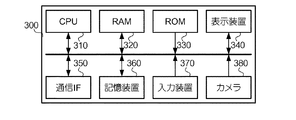
図3は、携帯端末300のハードウェア構成を示す図である。携帯端末300は、例えばスマートフォンである。携帯端末300は、映像信号出力装置の一例である。また、携帯端末300は、スクリーン200に表示された画像に対して指で操作が行われた場合には、この操作を画像に反映するための処理を行う。携帯端末300は、CPU310と、RAM(Random Access Memory)320と、ROM(Read Only Memory)330と、表示装置340と、通信IF350と、記憶装置360と、入力装置370と、撮影部又は撮影装置としてのカメラ380とを有する。
FIG. 3 is a diagram illustrating a hardware configuration of the
CPU310は、携帯端末300の他のハードウェアを制御する制御装置である。RAM320は、CPU310がプログラムを実行する際のワークエリアとして機能する揮発性の記憶装置である。ROM330は、データおよびプログラムを記憶した不揮発性の記憶装置である。表示装置340は、情報を表示する装置、例えば液晶ディスプレイである。通信IF350は、プロジェクター100と通信を行うインターフェースである。記憶装置360は、データおよびプログラムを記憶する書き換え可能な不揮発性の記憶装置である。入力装置370は、ユーザーの操作に応じた情報をCPU310に入力するための装置、例えば、キーボード、マウス、又はタッチスクリーンを含む。カメラ380は、画像を撮影する。以上の要素は、バスにより接続されている。
The
記憶装置360には、プロジェクター100に出力される画像データ361が記憶される。この画像データ361は、例えばプレゼンテーションの資料として用いられる画像を示すものであってもよいし、映画等の動画を示すものであってもよい。
The
また、記憶装置360には、描画アプリケーション363が記憶される。この描画アプリケーション363は、基本的には、記憶装置360に記憶された画像データ361をプロジェクター100の処理に適した映像信号に変換してプロジェクター100に送信する。例えば、描画アプリケーション363は、プロジェクター100が所定のフレームレートに対応する場合には、画像データ361を所定のフレームレートの映像信号に変換して送信する。
Further, the
ただし、描画アプリケーション363は、スクリーン200に表示された画像に対して指で操作が行われた場合には、この操作を反映した画像に応じた映像信号をプロジェクター100に送信する。例えば、描画アプリケーション363は、スクリーン200上にて手書きで情報を書き込む操作が行われた場合には、記憶装置360に記憶された画像データ361が示す画像と手書きで書き込まれた情報とを合成した画像に応じた映像信号をプロジェクター100に送信する。この映像信号も、上述した画像データ361に応じた映像信号と同様に、プロジェクター100の処理に適した形式を有する。
However, when an operation is performed with the finger on the image displayed on the
図4は、携帯端末300の機能構成を示す図である。携帯端末300は、CPU310が描画アプリケーション363を実行することにより、認識部311、検出部312、生成部313、合成部314、及び出力部315の機能を実現する。携帯端末300は、これらの機能を実現するコンピューターの一例である。これらの機能は、CPU310と他のハードウェア構成との協働により実現されてもよい。
FIG. 4 is a diagram illustrating a functional configuration of the
出力部315は、記憶装置360に記憶された画像データ361に応じた映像信号を出力する。プロジェクター100は、出力部315から出力された映像信号に応じた第1の画像をスクリーン200に投写する。カメラ380は、スクリーン200の画像を撮影する。認識部311は、カメラ380により撮影された画像に基づいて、手の形状を認識する。検出部312は、カメラ380により撮影された画像に基づいて、スクリーン200上での指の軌跡を検出する。生成部313は、検出部312により検出された軌跡に応じた第2の画像を生成する。合成部314は、生成部313により生成された第2の画像と記憶装置360に記憶された画像データ361に応じた第1の画像とを合成して合成画像250を生成する。出力部315は、合成画像250に応じた映像信号をプロジェクター100に出力する。
The
2.動作
図5は、表示システム10が行う投写処理を示すフローチャートである。ステップS101において、プロジェクター100は、携帯端末300から画像データ361に応じた映像信号が出力されると、この映像信号に応じた画像210をスクリーン200に投写する。この画像210は、表示画面の画像の一例である。具体的には、携帯端末300の出力部315により、記憶装置360に記憶された画像データ361(第1の画像)に応じた映像信号がプロジェクター100に送信される。プロジェクター100は、この映像信号を受信すると、受信した映像信号に応じた画像210をスクリーン200に投写する。これにより、図1に示すように、スクリーン200に画像210が表示される。なお、上述したように、携帯端末300とプロジェクター100とは無線で接続されているため、映像信号は無線で送信される。
2. Operation FIG. 5 is a flowchart showing a projection process performed by the
ステップS102において、携帯端末300のカメラ380は、スクリーン200を含む範囲の動画を撮影する。この動画は、連続して撮影された複数の画像により構成される。これらの画像は、順次出力される。
In step S <b> 102, the
ステップS103において、検出部312は、カメラ380から出力された画像に基づいて、スクリーン200における画像210の投写領域220を特定する。例えば、検出部312は、カメラ380から出力された画像と画像データ361が示す画像210とを比較し、相関の高い部分を投写領域220として特定する。
In step S <b> 103, the
ステップS104において、携帯端末300は、インタラクティブ処理を行う。
図6は、インタラクティブ処理を示すフローチャートである。ステップS201において、検出部312は、カメラ380から出力された画像に基づいて、ステップS103で特定された投写領域220からユーザーの手を検出する。例えば、検出部312は、カメラ380から出力された画像の投写領域220に手の特徴を有する部分が含まれる場合には、この部分を手として検出する。この特徴は、例えば色や形状である。投写領域220から手が検出されると(ステップS201:YES)、インタラクティブ処理はステップS202に進む。一方、投写領域220から手が検出されない場合には(ステップS201:NO)、カメラ380から出力された次の画像に基づいて、ステップS201の処理が行われる。
In step S104, the
FIG. 6 is a flowchart showing the interactive processing. In step S201, the
ステップS202において、認識部311は、ステップS201で検出された手の形状を認識する。例えば、認識部311は、検出された手の部分と様々な手の形状のパターンとをマッチングすることにより、手の形状を認識する。
In step S202, the
ステップS203において、生成部313は、ステップS202で認識された手の形状に応じて、ユーザーの操作を画像210に反映させるか否かを判断する。
In step S <b> 203, the
図7は、ユーザーの操作に用いられる手の形状の一例を示す図である。図7に示す例では、ユーザーの操作には、手の形状21又は22が用いられる。形状21は、指を一本だけ立てた形である。形状22は、五本の指を全て握った形である。図7に示す例では、生成部313は、ステップS202で形状21が認識された場合には、ユーザーの操作を画像210に反映させると判断する。この場合、インタラクティブ処理はステップS204に進む。一方、生成部313は、ステップS202で形状22が認識された場合には、ユーザーの操作を画像210に反映させないと判断する。この場合、インタラクティブ処理はステップS201に戻る。
FIG. 7 is a diagram illustrating an example of a hand shape used for a user operation. In the example shown in FIG. 7, the
ステップS204において、検出部312は、カメラ380から出力された画像に基づいて、指の軌跡を投写領域220上での指の軌跡として検出する。具体的には、検出部312は、カメラ380から出力された各画像における投写領域220上での指先の位置を示す座標を算出する。この時、指先がスクリーン200に接触している必要はない。カメラ380から出力した画像に基づいて、投写領域220上における指先に位置を示す座標が算出できるのであれば、スクリーン200から指先が離れていてもよい。検出部312は、算出した座標を時系列に沿って結んだ線を、指の軌跡として検出する。また、検出部312は、記憶装置360に記憶された画像データ361に応じた仮想スクリーンを設定し、投写領域220を仮想スクリーン上に投射変換する。この仮想スクリーンは、画像データ361に対応するものであり、例えば画像データ361と同じ縦横比を有する。これにより、投写領域220上での指の軌跡を示す座標が仮想スクリーンの座標系の座標に変換される。
In step S <b> 204, the
ステップS205において、生成部313は、ステップS204で検出された軌跡に応じた手書き画像240を生成する。この手書き画像240は、第2の画像の一例である。
In step S205, the
図8は、手書き画像240の生成の一例を示す図である。図8に示す例では、ユーザーは、スクリーン200に表示された画像210上にて指で線230を描く。この場合、線230を示す線画が手書き画像240として生成される。
FIG. 8 is a diagram illustrating an example of generation of the
なお、生成部313は、上述したステップS203でユーザーの操作を画像210に反映すると判断された場合には、手書き画像240を生成するが、ユーザーの操作を画像210に反映しないと判断された場合には、手書き画像240を生成しない。この判断は、ステップS202で認識された手の形状に応じて行われる。このように、生成部313は、ステップS202で認識された手の形状に応じて、手書き画像240の生成を制御する。また、この判断は、手や指がスクリーン200に接触しているか否かによって行ってもよい。接触しているか否かは手や指の影を利用して判断することができる。
The
ステップS206において、合成部314は、ステップS205で生成された手書き画像240と記憶装置360に記憶された画像データ361が示す画像210とを合成して合成画像250を生成する。このとき、合成部314は、仮想スクリーンにおける軌跡の座標に基づいて、手書き画像240がこの座標が示す位置に配置されるように、手書き画像240と画像210との位置を合わせて合成する。
In step S <b> 206, the combining
図9は、合成画像250の生成の一例を示す図である。図9に示す例では、画像210の上に手書き画像240を重ねることにより合成画像250が生成される。
FIG. 9 is a diagram illustrating an example of generation of the
ステップS207において、出力部315は、ステップS206で生成された合成画像250に応じた映像信号をプロジェクター100に送信する。
In step S207, the
プロジェクター100は、合成画像250に応じた映像信号を受信すると、受信した映像信号に応じた合成画像250をスクリーン200に投写する。これにより、スクリーン200に合成画像250が表示される。
When the
図10は、スクリーン200に表示された合成画像250の一例を示す図である。この合成画像250には、ユーザーの指で描かれた線230を示す手書き画像240が含まれる。このように、ユーザーは、スクリーン200に表示された画像210に対して手書きで情報を書き込むことができる。
FIG. 10 is a diagram illustrating an example of the
ユーザーにより手書きで書き込まれた情報がスクリーン200に表示されている間は、携帯端末300からプロジェクター100に合成画像250に応じた映像信号が出力される。一方、ユーザーにより手書きで書き込まれた情報がスクリーン200に表示されない間は、携帯端末300からプロジェクター100に画像データ361に応じた映像信号が出力される。
While information handwritten by the user is displayed on the
また、以下のタイミングで、ユーザーにより書き込まれた情報の表示と非表示とを切り替えてもよい。
(1)携帯端末300の入力装置370を用いて切り替え指示を入力する操作が行われたとき
(2)スクリーン200上で切り替え指示を入力する操作が行われたとき
(3)プロジェクター100によりスクリーン200に表示されている画像の基となる画像データが複数のページに区分された画像データである場合において、スクリーン200に表示されている画像のページの切り替えが行われたとき
Further, display and non-display of information written by the user may be switched at the following timing.
(1) When an operation for inputting a switching instruction is performed using the
例えば(2)の場合、画像データ361が示す画像210と切り替え操作用のメニュー画像とを合成した画像をスクリーン200に投写し、スクリーン200上でこのメニュー画像を選択する操作が行われたときに、ユーザーにより書き込まれた情報(例えば、手書き画像240)の表示と非表示とを切り替えてもよい。また、例えば(3)の場合、スクリーン200に表示された画像のページが切り替えられたときに、前のページの画像の表示中にユーザーにより書き込まれた情報(例えば、手書き画像240)を消去してもよい。
For example, in the case of (2), an image obtained by combining the
本実施形態では、携帯端末300を利用してインタラクティブ処理が行われるため、プロジェクター100は、赤外線カメラ等の専用のデバイスを備える必要がない。したがって、例えば指示体の位置を認識する機能をもたないような簡単な構成のプロジェクター100を用いて、プロジェクター100により投写された画像210に対して指で行われた操作をこの画像210に反映する機能を実現することができる。
In the present embodiment, since interactive processing is performed using the
また、従来の技術では、スクリーン200に表示された画像に対して手書きで情報を書き込む場合には、例えば描画を指示する操作を示すアイコンを合成した画像をスクリーン200に表示し、ユーザーはスクリーン200上でこのアイコンを選択する操作を行う必要があった。しかし、本実施形態によれば、このような操作を行わずに、手の形を例えば図7に示す形状21にするだけで、スクリーン200に表示された画像210に対して手書きで情報を書き込むことができる。
Further, in the conventional technology, when information is written by hand with respect to an image displayed on the
また、本実施形態では、手の形を図7に示す形状21にすれば、例えば指をスクリーン200から浮かせた状態で線230を描いても、手書き画像240が生成される。そのため、ユーザーは、スクリーン200に表示された画像210に対して手書きで情報を書き込む操作を行うときに、必ずしもスクリーン200に接触する必要がない。これにより、スクリーン200の劣化や損傷を抑制することができる。
In this embodiment, if the shape of the hand is the
3.変形例
本発明は上述の実施形態に限定されるものではなく、種々の変形実施が可能である。以下、変形例をいくつか説明する。以下の変形例のうち2つ以上のものが組み合わせて用いられてもよい。
3. Modifications The present invention is not limited to the above-described embodiments, and various modifications can be made. Hereinafter, some modifications will be described. Two or more of the following modifications may be used in combination.
上述した実施形態において、生成部313は、ステップS202で認識された手の形状に応じて、手書き画像240で用いられる線の太さを変化させてもよい。
In the embodiment described above, the
図11は、この変形例に係るユーザーの操作に用いられる手の形状の一例を示す図である。図11に示す例では、ユーザーの操作には、手の形状21、23、又は24が用いられる。形状21は、上述したように、指を一本だけ立てた形である。形状23は、指を二本立てた形である。形状24は、指を三本立てた形である。この場合、ステップS203では、ステップS202で形状21、形状23、又は24が認識された場合には、ユーザーの操作を画像210に反映すると判断される。ステップS205では、ステップS202で形状21が認識された場合には、細線を用いて手書き画像240が生成される。ステップS202で形状23が認識された場合には、太線を用いて手書き画像240が生成される。ステップS202で形状24が認識された場合には、極太線を用いて手書き画像240が生成される。
FIG. 11 is a diagram illustrating an example of a hand shape used for a user operation according to this modification. In the example shown in FIG. 11, the
上述した実施形態において、生成部313は、ステップS202で認識された手の形状に応じて、手書き画像240で用いられる線の種別を変化させてもよい。
In the embodiment described above, the
図12は、この変形例に係るユーザーの操作に用いられる手の形状の一例を示す図である。図12に示す例では、ユーザーの操作には、手の形状21又は25が用いられる。形状21は、指を一本だけ立てた右手の形である。形状25は、指を一本だけ立てた左手の形である。この場合、ステップS203では、ステップS202で形状21又は形状25が認識された場合に、ユーザーの操作を画像210に反映すると判断される。ステップS205では、ステップS202で形状21が認識された場合には、実線を用いて手書き画像240が生成される。ステップS202で形状25が認識された場合には、破線を用いて手書き画像240が生成される。
FIG. 12 is a diagram illustrating an example of a hand shape used for a user operation according to this modification. In the example shown in FIG. 12, the
上述した実施形態において、携帯端末300は、ステップS202で認識された指の形状に応じて、スクリーン200に表示された画像210又は合成画像250を変化させてもよい。
In the embodiment described above, the
図13は、この変形例に係るユーザーの操作に用いられる手の形状の一例を示す図である。図13に示す例では、ユーザーの操作には、手の形状26、27又は28が用いられる。形状26は、指を五本立てた形である。形状27は、指を一本だけ立ててその指先をユーザーの右に向けた形である。形状28は、指を一本だけ立ててその指先をユーザーの左に向けた形である。
FIG. 13 is a diagram illustrating an example of a hand shape used for a user operation according to this modification. In the example shown in FIG. 13, a
図13に示す例では、形状26は、手書き画像240を消去する操作に用いられる。例えば、図10に示す合成画像250に含まれる手書き画像240部分を消去したい場合、ユーザーは、手の形を形状26にして、スクリーン200に表示された合成画像250に含まれる手書き画像240の部分の上に重ねる。この場合、ステップS202で形状26が認識されると、携帯端末300は、合成画像250から手書き画像240部分を消去した画像を生成し、生成した画像に応じた映像信号をプロジェクター100に送信する。このとき、携帯端末300は、手書き画像240部分のうちユーザーの手の位置に対応する部分だけを消去してもよいし、手書き画像240部分を全て消去してもよいし、プロジェクター100は、この映像信号を受信すると、受信した映像信号に応じた画像をスクリーン200に投写する。これにより、スクリーン200には、手書き画像240が消去された画像が表示される。
In the example illustrated in FIG. 13, the
図13に示す例では、形状27は、スクリーン200に表示された画像のページを送る操作に用いられる。この場合、記憶装置360には、複数のページに区分された画像データが記憶される。ステップS202で形状27が認識されると、出力部315は、記憶装置360から次のページの画像データを読み出して、この画像データに応じた映像信号をプロジェクター100に送信する。例えば、スクリーン200に10ページ目の画像が表示されている場合には、11ページ目の画像データに応じた映像信号がプロジェクター100に送信される。プロジェクター100は、この映像信号を受信すると、受信した映像信号に応じた次のページの画像をスクリーン200に投写する。これにより、次のページの画像がスクリーン200に表示される。
In the example illustrated in FIG. 13, the
図13に示す例では、形状28は、スクリーン200に表示された画像のページを戻す操作に用いられる。この場合、記憶装置360には、複数のページに区分された画像データが記憶される。ステップS202で形状28が認識されると、出力部315は、記憶装置360から前のページの画像データを読み出して、この画像データに応じた映像信号をプロジェクター100に送信する。例えば、スクリーン200に10ページ目の画像が表示されている場合には、9ページ目の画像データに応じた映像信号がプロジェクター100に送信される。プロジェクター100は、この映像信号を受信すると、受信した映像信号に応じた前のページの画像をスクリーン200に投写する。これにより、前のページの画像がスクリーン200に表示される。
In the example shown in FIG. 13, the
上述した実施形態及び変形例で説明した手の形状は、一例である。上述した操作は、他の形状を用いて行われてもよい。また、上述した操作に用いられる手の形状は、ユーザー毎に設定されてもよい。さらに、上述した操作に用いられる手の形状は、予め携帯端末300に記憶されてもよいし、外部装置に記憶され、携帯端末300にダウンロードされてもよい。この外部装置は、例えばクラウドコンピューティングを利用してサービスを提供するクラウドサーバー装置であってもよい。
The shape of the hand described in the above-described embodiments and modifications is an example. The operations described above may be performed using other shapes. Moreover, the shape of the hand used for the above-described operation may be set for each user. Furthermore, the shape of the hand used for the above-described operation may be stored in advance in the
上述した実施形態において、例えば携帯端末300がスクリーン200に向けて配置されていない場合には、ステップS103で投写領域220が特定されない。この場合、携帯端末300は、表示装置340に「スクリーン200の方へ向けてください」というメッセージを表示してもよい。
In the embodiment described above, for example, when the
上述した実施形態において、手の形状を認識し易くするために、ユーザーは特殊な指サックや手袋を付けて操作を行ってもよい。また、ユーザーは、ペンや棒等の指示体を用いて操作を行ってもよい。この指示体は、赤外光を発する機能を有する必要はない。この場合、検出部312は、カメラ380から出力された画像に基づいてペンや棒等の指示体の形状や位置などを認識する。
In the above-described embodiment, in order to easily recognize the shape of the hand, the user may perform an operation with a special finger sack or gloves. In addition, the user may perform an operation using an indicator such as a pen or a stick. This indicator does not need to have a function of emitting infrared light. In this case, the
上述した実施形態において、携帯端末300の機能は、複数のアプリケーションにより実現されてもよい。例えば、図4に示す認識部311、検出部312、生成部313、及び合成部314と、出力部315とが異なるアプリケーションにより実現されてもよい。
In the embodiment described above, the function of the
上述した実施形態において、画像データ361が外部装置に記憶されてもよい。この外部装置は、他の携帯端末であってもよいし、クラウドコンピューティングを利用してサービスを提供するクラウドサーバー装置であってもよい。この場合、外部装置と携帯端末300とは、有線又は無線で接続される。携帯端末300は、外部装置から画像データ361を取得して実施形態で説明した処理を行う。この変形例では、外部装置は記憶装置として機能する。
In the embodiment described above, the
上述した実施形態において、携帯端末300に代えて外部装置が実施形態で説明した処理の一部又は全部を行ってもよい。この外部装置は、他の携帯端末であってもよいし、クラウドコンピューティングを利用してサービスを提供するクラウドサーバー装置であってもよい。この場合、外部装置は、図4に示す機能の少なくとも一部を有する。外部装置が図4に示す機能を全て有する場合には、外部装置が出力装置として機能する。一方、外部装置が図4に示す機能の一部を有する場合には、携帯端末300と外部装置とが協働して出力装置として機能する。
In the embodiment described above, an external device may perform part or all of the processing described in the embodiment instead of the
例えば、外部装置が画像データ361を記憶するとともに、合成部314の機能を有していてもよい。この場合、携帯端末300と外部装置とは、有線又は無線で接続される。携帯端末300は、生成部313により生成された手書き画像240を示す画像データを外部装置に送信する。外部装置は、この画像データを受信すると、受信した画像データに基づいて合成画像250を生成する。外部装置は、この合成画像250を示す合成画像データを携帯端末300に送信する。携帯端末300は、外部装置から合成画像データを受信すると、受信した合成画像データに応じた映像信号をプロジェクター100に送信する。あるいは、外部装置は、合成画像250に応じた映像信号をプロジェクター100に送信してもよい。他の例として、プロジェクター100がカメラ380を備え、さらに図4に示す機能を全て備えてもよい。
For example, the external device may store the
携帯端末300が行う処理の順序は、実施形態で説明した順序に限定されない。例えば、図5に示すステップS103の処理が、図6に示すインタラクティブ処理のステップS210の処理の前に行われてもよい。
The order of processing performed by the
上述した携帯端末300は、スマートフォンに限定されない。例えば携帯端末300は、ノート型パーソナルコンピューター、タブレット型コンピューター、又はデジタルカメラであってもよい。
The
上述した表示装置は、プロジェクター100に限定されない。例えば、液晶ディスプレイ、有機EL(Electro Luminescence)ディスプレイ、プラズマディスプレイなどの投写型以外の表示装置であってよい。
The display device described above is not limited to the
CPU310によって実行されるプログラムは、磁気記録媒体(磁気テープ、磁気ディスク(HDD、FD(Flexible Disk))など)、光記録媒体(光ディスク(CD(Compact Disk)、DVD(Digital Versatile Disk))など)、光磁気記録媒体、半導体メモリー(フラッシュROMなど)などのコンピューター読取り可能な記録媒体に記憶した状態で提供されてもよい。また、このプログラムは、インターネットのようなネットワーク経由でダウンロードされてもよい。
Programs executed by the
10…表示システム、100…プロジェクター、200…スクリーン、300…携帯端末、311…認識部、312…検出部、313…生成部、314…合成部、315…出力部
DESCRIPTION OF
Claims (13)
前記映像信号に応じて前記表示装置が表示した画像と、指示体とを、ともに撮影する撮影部と、
前記撮影部が撮影した画像において、前記第1の画像との比較により、前記表示装置により前記画像が表示された領域を特定し、前記撮影部が撮影した画像に基づいて、前記特定した領域から前記指示体の軌跡を検出する検出部と、
前記表示装置により前記画像が表示された領域が、前記撮影部が撮影した画像に含まれない場合には、前記撮影部を前記領域の方へ向けることを要求するメッセージを表示する表示部と、
前記検出部が検出した前記軌跡に応じた第2の画像を生成する生成部と、
前記生成部が生成した前記第2の画像と前記第1の画像とを合成して合成画像を生成する合成部と、を備え、
前記出力部は、前記合成部が生成した前記合成画像に応じた映像信号を前記表示装置に出力することを特徴とする映像信号出力装置。 An output unit for outputting a video signal corresponding to the first image to the display device;
A photographing unit that photographs both the image displayed by the display device according to the video signal and the indicator;
In an image in which the imaging unit has captured, by comparison with the first image, the image to identify the region displayed, based on the image before Symbol imaging unit has captured by the display device, before Kitoku constant a detector for detecting the locus of the indicator from realm that,
If the area where the image is displayed by the display device is not included in the image captured by the imaging unit, a display unit that displays a message requesting that the imaging unit be directed toward the area;
A generating unit that generates a second image corresponding to the locus detected by the detecting unit;
A combining unit that combines the second image generated by the generating unit and the first image to generate a combined image;
The said output part outputs the video signal according to the said synthesized image which the said synthetic | combination part produced | generated to the said display apparatus, The video signal output apparatus characterized by the above-mentioned.
前記生成部は、前記認識部が認識した前記指示体の形状に応じて、前記第2の画像の生成を制御することを特徴とする
請求項1に記載の映像信号出力装置。 The video signal output device further includes a recognition unit that recognizes the shape of the indicator based on the image captured by the imaging unit,
The video signal output device according to claim 1, wherein the generation unit controls generation of the second image according to a shape of the indicator recognized by the recognition unit.
前記生成部は、前記認識部が認識した前記指示体の形状に応じて、前記第2の画像を変化させることを特徴とする
請求項1に記載の映像信号出力装置。 The video signal output device further includes a recognition unit that recognizes the shape of the indicator based on the image captured by the imaging unit,
The video signal output apparatus according to claim 1, wherein the generation unit changes the second image according to a shape of the indicator recognized by the recognition unit.
前記生成部は、前記認識部が認識した前記指示体の形状に応じて、前記線画で用いられる線を変化させることを特徴とする
請求項3に記載の映像信号出力装置。 The second image is a line drawing corresponding to the locus,
The video signal output device according to claim 3, wherein the generation unit changes a line used in the line drawing according to a shape of the indicator recognized by the recognition unit.
請求項1ないし請求項4のいずれか1項に記載の映像信号出力装置。 The video signal output apparatus according to claim 1, wherein the indicator is a hand or a finger.
請求項1ないし請求項5のいずれか1項に記載の映像信号出力装置。 The video signal output device according to any one of claims 1 to 5, wherein the video signal output device is a mobile terminal.
請求項1ないし請求項6のいずれか1項に記載の映像信号出力装置。 The video signal output device according to any one of claims 1 to 6, wherein the display device is a projector.
(B)前記撮影された画像において、前記第1の画像との比較により、前記表示装置により前記画像が表示された領域を特定するステップと、
(C)前記撮影された画像に基づいて、前記特定された領域から前記指示体の軌跡を検出するステップと、
(D)前記検出された軌跡に応じた第2の画像を生成するステップと、
(E)前記生成された第2の画像と前記第1の画像とを合成して合成画像を生成するステップと、
(F)前記生成された合成画像に応じた映像信号を前記表示装置に出力するステップと、
前記表示装置により前記画像が表示された領域が、前記ステップ(A)で撮影した前記画像に含まれない場合には、前記画像を撮影した撮影部を前記領域の方へ向けることを要求するメッセージを表示するステップと
を有する映像信号出力方法。 (A) a step of photographing both the image displayed by the display device according to the video signal corresponding to the first image and the indicator;
(B) in the photographed image, specifying a region where the image is displayed by the display device by comparison with the first image;
(C) detecting a locus of the indicator from the identified area based on the captured image;
(D) generating a second image according to the detected locus;
(E) generating a composite image by combining the generated second image and the first image;
(F) outputting a video signal corresponding to the generated composite image to the display device ;
If the area where the image is displayed by the display device is not included in the image captured in step (A), a message requesting that the imaging unit that captured the image be directed toward the area video signal output method and a step of displaying.
前記ステップ(D)は、前記認識された指示体の形状に応じて、前記第2の画像の生成を制御することを特徴とする
請求項8に記載の映像信号出力方法。 The step (C) further comprises the step of recognizing the shape of the indicator based on the image taken in the step (A),
The video signal output method according to claim 8 , wherein the step (D) controls generation of the second image in accordance with the shape of the recognized indicator.
前記ステップ(D)は、前記認識された指示体の形状に応じて、前記第2の画像を変化させることを特徴とする
請求項8に記載の映像信号出力装置。 The step (C) further comprises the step of recognizing the shape of the indicator based on the image taken in the step (A),
The video signal output device according to claim 8 , wherein the step (D) changes the second image according to the shape of the recognized indicator.
前記ステップ(D)は、前記認識された指示体の形状に応じて、前記線画で用いられる線を変化させることを特徴とする
請求項10に記載の映像信号出力方法。 The second image is a line drawing corresponding to the locus,
The video signal output method according to claim 10 , wherein the step (D) changes a line used in the line drawing according to the recognized shape of the indicator.
Priority Applications (2)
| Application Number | Priority Date | Filing Date | Title |
|---|---|---|---|
| JP2014053671A JP6349811B2 (en) | 2014-03-17 | 2014-03-17 | Video signal output device, video signal output method, and program |
| US14/638,320 US20150261385A1 (en) | 2014-03-17 | 2015-03-04 | Picture signal output apparatus, picture signal output method, program, and display system |
Applications Claiming Priority (1)
| Application Number | Priority Date | Filing Date | Title |
|---|---|---|---|
| JP2014053671A JP6349811B2 (en) | 2014-03-17 | 2014-03-17 | Video signal output device, video signal output method, and program |
Publications (3)
| Publication Number | Publication Date |
|---|---|
| JP2015176461A JP2015176461A (en) | 2015-10-05 |
| JP2015176461A5 JP2015176461A5 (en) | 2017-04-27 |
| JP6349811B2 true JP6349811B2 (en) | 2018-07-04 |
Family
ID=54068878
Family Applications (1)
| Application Number | Title | Priority Date | Filing Date |
|---|---|---|---|
| JP2014053671A Active JP6349811B2 (en) | 2014-03-17 | 2014-03-17 | Video signal output device, video signal output method, and program |
Country Status (2)
| Country | Link |
|---|---|
| US (1) | US20150261385A1 (en) |
| JP (1) | JP6349811B2 (en) |
Families Citing this family (6)
| Publication number | Priority date | Publication date | Assignee | Title |
|---|---|---|---|---|
| JP6286836B2 (en) * | 2013-03-04 | 2018-03-07 | 株式会社リコー | Projection system, projection apparatus, projection method, and projection program |
| JP6037900B2 (en) | 2013-03-11 | 2016-12-07 | 日立マクセル株式会社 | Operation detection device and operation detection method |
| JP6631181B2 (en) * | 2015-11-13 | 2020-01-15 | セイコーエプソン株式会社 | Image projection system, projector, and method of controlling image projection system |
| JP6728849B2 (en) * | 2016-03-25 | 2020-07-22 | セイコーエプソン株式会社 | Display device and display device control method |
| CN108961414A (en) * | 2017-05-19 | 2018-12-07 | 中兴通讯股份有限公司 | A kind of display control method and device |
| WO2023283941A1 (en) * | 2021-07-16 | 2023-01-19 | 华为技术有限公司 | Screen projection image processing method and apparatus |
Family Cites Families (9)
| Publication number | Priority date | Publication date | Assignee | Title |
|---|---|---|---|---|
| US6798446B2 (en) * | 2001-07-09 | 2004-09-28 | Logitech Europe S.A. | Method and system for custom closed-loop calibration of a digital camera |
| JP2010146086A (en) * | 2008-12-16 | 2010-07-01 | Konica Minolta Business Technologies Inc | Data delivery system, data delivery device, data delivery method, and data delivery program |
| JP2011085966A (en) * | 2009-10-13 | 2011-04-28 | Sony Corp | Information processing device, information processing method, and program |
| JP2011203830A (en) * | 2010-03-24 | 2011-10-13 | Seiko Epson Corp | Projection system and method of controlling the same |
| US8818027B2 (en) * | 2010-04-01 | 2014-08-26 | Qualcomm Incorporated | Computing device interface |
| JP2012108771A (en) * | 2010-11-18 | 2012-06-07 | Panasonic Corp | Screen operation system |
| US8847881B2 (en) * | 2011-11-18 | 2014-09-30 | Sony Corporation | Gesture and voice recognition for control of a device |
| US9165381B2 (en) * | 2012-05-31 | 2015-10-20 | Microsoft Technology Licensing, Llc | Augmented books in a mixed reality environment |
| WO2014080829A1 (en) * | 2012-11-22 | 2014-05-30 | シャープ株式会社 | Data input device |
-
2014
- 2014-03-17 JP JP2014053671A patent/JP6349811B2/en active Active
-
2015
- 2015-03-04 US US14/638,320 patent/US20150261385A1/en not_active Abandoned
Also Published As
| Publication number | Publication date |
|---|---|
| JP2015176461A (en) | 2015-10-05 |
| US20150261385A1 (en) | 2015-09-17 |
Similar Documents
| Publication | Publication Date | Title |
|---|---|---|
| JP6349811B2 (en) | Video signal output device, video signal output method, and program | |
| JP5087532B2 (en) | Terminal device, display control method, and display control program | |
| US8827461B2 (en) | Image generation device, projector, and image generation method | |
| US20170255253A1 (en) | Projector and image drawing method | |
| US9898996B2 (en) | Display apparatus and display control method | |
| US20180061371A1 (en) | Projector and display control method | |
| US20160252984A1 (en) | Display apparatus, display control method, and computer program | |
| JP2012053584A (en) | Information display system and program | |
| JP6451225B2 (en) | Display device, projector, and display control method | |
| JP2000259338A (en) | Input system, display system, presentation system and information storage medium | |
| US10338750B2 (en) | Display apparatus, projector, and display control method | |
| WO2018109876A1 (en) | Display device, electronic blackboard system, and user interface setting method | |
| JP2021197024A (en) | Display unit, display method, and program | |
| US8629846B2 (en) | Information processing apparatus and information processing method | |
| JP7331578B2 (en) | Display device, image display method, program | |
| JP7342501B2 (en) | Display device, display method, program | |
| US11698575B2 (en) | Projective transformation matrix determination method, projector, and determination system | |
| JP7480608B2 (en) | Display device, display method, and program | |
| US20230254555A1 (en) | Electronic apparatus, control method therefor, and computer-readable storage medium storing program | |
| JP6608080B1 (en) | Projector system | |
| US20230276015A1 (en) | Electronic apparatus, method of controlling the same, and computer-readable storage medium storing program | |
| KR101700117B1 (en) | Interactive electronic authoring tool, computer apparatus and method for providing the same | |
| JP2022143517A (en) | Display device, method for display, and program | |
| JP2023046943A (en) | Control method of display system and display system | |
| US9389778B2 (en) | Image capturing method of touch display module and electronic device |
Legal Events
| Date | Code | Title | Description |
|---|---|---|---|
| A521 | Request for written amendment filed |
Free format text: JAPANESE INTERMEDIATE CODE: A523 Effective date: 20170316 |
|
| A621 | Written request for application examination |
Free format text: JAPANESE INTERMEDIATE CODE: A621 Effective date: 20170316 |
|
| A977 | Report on retrieval |
Free format text: JAPANESE INTERMEDIATE CODE: A971007 Effective date: 20171113 |
|
| A131 | Notification of reasons for refusal |
Free format text: JAPANESE INTERMEDIATE CODE: A131 Effective date: 20171121 |
|
| A521 | Request for written amendment filed |
Free format text: JAPANESE INTERMEDIATE CODE: A523 Effective date: 20180117 |
|
| A02 | Decision of refusal |
Free format text: JAPANESE INTERMEDIATE CODE: A02 Effective date: 20180206 |
|
| A521 | Request for written amendment filed |
Free format text: JAPANESE INTERMEDIATE CODE: A523 Effective date: 20180409 |
|
| A911 | Transfer to examiner for re-examination before appeal (zenchi) |
Free format text: JAPANESE INTERMEDIATE CODE: A911 Effective date: 20180416 |
|
| TRDD | Decision of grant or rejection written | ||
| A01 | Written decision to grant a patent or to grant a registration (utility model) |
Free format text: JAPANESE INTERMEDIATE CODE: A01 Effective date: 20180508 |
|
| A61 | First payment of annual fees (during grant procedure) |
Free format text: JAPANESE INTERMEDIATE CODE: A61 Effective date: 20180521 |
|
| R150 | Certificate of patent or registration of utility model |
Ref document number: 6349811 Country of ref document: JP Free format text: JAPANESE INTERMEDIATE CODE: R150 |