JP6346755B2 - Solar power panel - Google Patents

Solar power panel Download PDF

Info

Publication number
JP6346755B2
JP6346755B2 JP2014034636A JP2014034636A JP6346755B2 JP 6346755 B2 JP6346755 B2 JP 6346755B2 JP 2014034636 A JP2014034636 A JP 2014034636A JP 2014034636 A JP2014034636 A JP 2014034636A JP 6346755 B2 JP6346755 B2 JP 6346755B2
Authority
JP
Japan
Prior art keywords
fitting
power generation
photovoltaic power
receiving
column
Prior art date
Legal status (The legal status is an assumption and is not a legal conclusion. Google has not performed a legal analysis and makes no representation as to the accuracy of the status listed.)
Expired - Fee Related
Application number
JP2014034636A
Other languages
Japanese (ja)
Other versions
JP2015158116A (en
Inventor
広瀬 宣雄
宣雄 広瀬
加藤 文雄
文雄 加藤
Original Assignee
株式会社サンレール
Priority date (The priority date is an assumption and is not a legal conclusion. Google has not performed a legal analysis and makes no representation as to the accuracy of the date listed.)
Filing date
Publication date
Application filed by 株式会社サンレール filed Critical 株式会社サンレール
Priority to JP2014034636A priority Critical patent/JP6346755B2/en
Publication of JP2015158116A publication Critical patent/JP2015158116A/en
Application granted granted Critical
Publication of JP6346755B2 publication Critical patent/JP6346755B2/en
Expired - Fee Related legal-status Critical Current
Anticipated expiration legal-status Critical

Links

Images

Classifications

    • YGENERAL TAGGING OF NEW TECHNOLOGICAL DEVELOPMENTS; GENERAL TAGGING OF CROSS-SECTIONAL TECHNOLOGIES SPANNING OVER SEVERAL SECTIONS OF THE IPC; TECHNICAL SUBJECTS COVERED BY FORMER USPC CROSS-REFERENCE ART COLLECTIONS [XRACs] AND DIGESTS
    • Y02TECHNOLOGIES OR APPLICATIONS FOR MITIGATION OR ADAPTATION AGAINST CLIMATE CHANGE
    • Y02BCLIMATE CHANGE MITIGATION TECHNOLOGIES RELATED TO BUILDINGS, e.g. HOUSING, HOUSE APPLIANCES OR RELATED END-USER APPLICATIONS
    • Y02B10/00Integration of renewable energy sources in buildings
    • Y02B10/10Photovoltaic [PV]
    • YGENERAL TAGGING OF NEW TECHNOLOGICAL DEVELOPMENTS; GENERAL TAGGING OF CROSS-SECTIONAL TECHNOLOGIES SPANNING OVER SEVERAL SECTIONS OF THE IPC; TECHNICAL SUBJECTS COVERED BY FORMER USPC CROSS-REFERENCE ART COLLECTIONS [XRACs] AND DIGESTS
    • Y02TECHNOLOGIES OR APPLICATIONS FOR MITIGATION OR ADAPTATION AGAINST CLIMATE CHANGE
    • Y02EREDUCTION OF GREENHOUSE GAS [GHG] EMISSIONS, RELATED TO ENERGY GENERATION, TRANSMISSION OR DISTRIBUTION
    • Y02E10/00Energy generation through renewable energy sources
    • Y02E10/50Photovoltaic [PV] energy

Description

本発明は、平地及び傾斜地を含む地上ならびにビル屋上の如き陸屋根に設置する太陽光発電パネル架台に関する。   The present invention relates to a photovoltaic power generation panel mount that is installed on a flat roof such as a flat roof and an inclined land, and a flat roof such as a rooftop of a building.

近年、環境保護、省資源、CO2 削減等の観点から、太陽電池を利用した太陽光発電システムが急速に普及しており、大きな発電量を得るために複数枚の太陽光発電パネル(太陽電池モジュール)を縦横に平面的に並べた太陽電池アレイが一般化し、更にはメガソーラーやギガソーラーとして多数基の太陽電池アレイを並設した大規模太陽光発電施設も増加しつつある。しかるに、一般的に太陽電池アレイは、複数枚の太陽光発電パネル(太陽電池モジュール)を平面的に並べた短辺数m、長辺数m〜数十mといった大型で且つ重い上、受光効率面より所定の傾斜角度で配置することで風圧を受け易く、また地震による揺れの影響も受け易いため、大きな構造的強度が要求され、加えて据付施工の容易化、コスト削減等も要求される。 In recent years, solar power generation systems using solar cells are rapidly spreading from the viewpoint of environmental protection, resource saving, CO 2 reduction, etc. In order to obtain a large amount of power generation, a plurality of solar power generation panels (solar cells) Solar cell arrays in which modules) are arranged horizontally and vertically have become common, and large-scale photovoltaic power generation facilities in which a large number of solar cell arrays are arranged side by side as mega solar and giga solar are also increasing. However, in general, a solar cell array is large and heavy with a short side number m and a long side number m to several tens of meters in which a plurality of photovoltaic power generation panels (solar cell modules) are arranged in a plane, and has a light receiving efficiency. Arranging at a predetermined inclination angle from the surface makes it easy to receive wind pressure and is also susceptible to shaking due to earthquakes, which requires a large structural strength, and also requires easy installation and cost reduction. .

従来、このような太陽電池アレイを地上や陸屋根に据付けする手段として、複数本の縦桟(垂木)と横桟(桁)とを交叉部で連結した格子状の受けフレームによって太陽電池アレイを支承し、地上や陸屋根に設けたコンクリート製の土台や杭、建屋の屋根に設けた受け金具等のベースに対し、該受けフレームを下位側桟の要所において支柱もしくは支柱と取付金具を介して支持させる方式が多用されている。例えば、特許文献1に開示される据付手段では、太陽電池アレイの長手方向(左右方向)に沿って複数の支柱を間隔をあけて突設し、太陽光発電パネルを支承する受けフレームの前後傾斜方向に沿う縦桟の中間位置に各支柱の上端部を接続すると共に、各支柱の胴部と各縦桟の前部側又は前後両側部との間に傾斜アームを連結している。また、特許文献2に開示される据付手段では、太陽光発電パネルを支承する受けフレームを前後及び左右に配列した支柱で支承すると共に、前後及び左右に隣接する支柱間に斜めや水平の補強桟を連結している。   Conventionally, as a means for installing such a solar cell array on the ground or on a flat roof, the solar cell array is supported by a grid-shaped receiving frame in which a plurality of vertical beams (rafters) and horizontal beams (girder) are connected at crossovers. The support frame is supported at the main points of the lower side rails via posts or support posts and mounting brackets against the bases of concrete foundations and piles provided on the ground and flat roofs, and the bases of support fixtures provided on the roof of the building. The method of letting go is used a lot. For example, in the installation means disclosed in Patent Document 1, a plurality of support columns are protruded at intervals along the longitudinal direction (left-right direction) of the solar cell array, and the receiving frame that supports the photovoltaic power generation panel is inclined forward and backward. The upper end of each column is connected to an intermediate position of the vertical beam along the direction, and an inclined arm is connected between the trunk of each column and the front side or both front and rear sides of each vertical beam. Further, in the installation means disclosed in Patent Document 2, the receiving frame for supporting the photovoltaic power generation panel is supported by columns arranged in the front-rear and left-right directions, and oblique and horizontal reinforcing bars are disposed between the columns adjacent to the front-rear and left-right. Are connected.

特開2011−220096号公報(図1,図42,図43)Japanese Patent Laying-Open No. 2011-220096 (FIGS. 1, 42, and 43) 実用新案登録第3171824号公報(図1)Utility Model Registration No. 3171824 (FIG. 1)

しかしながら、従来の太陽光発電パネル架台では、太陽光発電パネルを支承する受けフレームが複数本の縦桟と横桟とを交叉部で連結した格子状構造であるため、縦桟と横桟とを各交叉部で連結するのに多大な手間と時間を要し、また縦桟及び横桟と両者を連結する金具を使用することに加え、受けフレームの重量が大きく、耐荷重面より支柱等に高強度な部材を使用することで、部材コストが嵩むという問題があった。更に、概して従来の太陽光発電パネル架台の場合、受けフレームと支柱上部との連結、土台側と支柱下部との連結、支柱の高さ調整や位置調整等にも煩雑な操作を要し、それだけ作業性が悪く施工コストも高く付くという難点があった。   However, in the conventional photovoltaic power generation panel mount, the receiving frame for supporting the photovoltaic power generation panel has a lattice structure in which a plurality of vertical beams and horizontal beams are connected at the crossing portion. It takes a lot of labor and time to connect at each crossover, and in addition to using vertical and horizontal rails and metal fittings to connect both, the weight of the receiving frame is large, and it is more difficult to connect it to the support column than the load bearing surface. The use of a high strength member has a problem that the member cost increases. Furthermore, in general, in the case of conventional photovoltaic power generation panel mounts, complicated operations are required for the connection between the receiving frame and the upper part of the support, the connection between the base and the lower part of the support, the height adjustment and the position adjustment of the support, etc. The workability was poor and the construction cost was high.

本発明は、上述の事情に鑑みて、太陽光発電パネル架台として、構造的に極めて簡素であって容易に能率よく施工でき、しかも全体として大きな構体強度を備え、地震時の大きな揺れや強風時の大きな風圧に充分に対応でき、施工コスト及び材料コストも少なくて済むものを提供することを目的としている。   In view of the above-mentioned circumstances, the present invention is structurally extremely simple as a photovoltaic power generation panel mount, can be easily and efficiently constructed, and has a large structure strength as a whole, during a large shake or strong wind during an earthquake. The object of the present invention is to provide an apparatus that can sufficiently cope with a large wind pressure and that requires less construction cost and material cost.

上記目的を達成するための手段を図面の参照符号を付して示せば、請求項1の発明に係る太陽光発電パネル架台は、低位側の左右一対の前部支柱1A,1Aと、高位側の左右一対の後部支柱1B,1Bと、各々前部支柱1A及び後部支柱1Bに支持されて前後傾斜方向に沿って配置した左右一対の受け桟2,2と、両受け桟2,2上に前後に配列して取り付けられた複数枚の太陽光発電パネルPとを備え、左右の前部支柱1A,1A間には2本の正面ブレース3A,3Aが、左右の後部支柱1B,1B間には2本の背面ブレース3B,3Bが、それぞれX字状に交叉して架設され、各受け桟2の中間部と前部支柱1Aの下部との間に第1の側面ブレース4Aが架設されると共に、該受け桟2の中間部と後部支柱1Bの下部との間に第2の側面ブレース4Bが架設されてなり、
前部支柱1A及び後部支柱1Bと受け桟2が断面略矩形のアルミ型材からなり、前部支柱1A及び後部支柱1Bの上端側に前後対向壁部1a,1aの切除による切欠嵌合部11が形成され、該切欠嵌合部11を受け桟2に下方から跨嵌した嵌合部分をボルト止めすることにより、前部支柱1A及び後部支柱1Bと受け桟2とが連結されてなり、
受け桟2の前部側が前部支柱1による支持部よりも前方へ長く張出し、その張出部20と前部支柱1Aの下部との間に第3の側面ブレース4Cが架設されてなり、
且つ、各側面ブレース4A〜4Cは、断面略矩形の中空アルミ型材からなり、その内面側の左右方向の対向面に長手方向に連続する突条部41,41が形成され、上端側及び下端側に前後対向壁部4a,4aの切除による切欠嵌合部42,43を備え、左右対向壁部4b,4bに突条部41,41を有する上端側の切欠嵌合部42を受け桟2に下方から跨嵌する一方、左右対向壁部4b,4bの該突条部41,41の切除によって開き幅を広くした下端側の切欠嵌合部43を前部支柱1A又は後部支柱1Bに跨嵌し、これら嵌合部分でボルト止めしてなるものとしている。
If means for achieving the above object is shown with reference numerals in the drawings, the photovoltaic power generation panel mount according to the invention of claim 1 includes a pair of front columns 1A and 1A on the left and right sides on the lower side and a higher side. A pair of left and right rear bars 1B, 1B, a pair of left and right receiving bars 2, 2 supported by the front column 1A and the rear column 1B and arranged along the front-rear tilt direction, and both receiving bars 2, 2 A plurality of photovoltaic power generation panels P that are arranged in the front-rear direction, and two front braces 3A, 3A are provided between the left and right front columns 1A, 1A, and between the left and right rear columns 1B, 1B. The two back braces 3B and 3B are respectively installed in an X-shaped manner, and a first side brace 4A is provided between the intermediate portion of each receiving bar 2 and the lower portion of the front support column 1A. And a second side surface between the intermediate portion of the receiving bar 2 and the lower portion of the rear column 1B. Ri Na race 4B is bridged,
The front strut 1A, the rear strut 1B, and the receiving bar 2 are made of an aluminum mold having a substantially rectangular cross section, and a notch fitting portion 11 is formed on the upper end side of the front strut 1A and the rear strut 1B by excising the front and rear facing walls 1a and 1a. The front strut 1A and the rear strut 1B are connected to the receiving bar 2 by bolting the fitting part formed and bolted to the receiving bar 2 from below to receive the notch fitting part 11.
The front side of the receiving bar 2 extends forward longer than the support portion by the front support column 1, and a third side brace 4C is installed between the extension 20 and the lower portion of the front support column 1A.
Each of the side braces 4A to 4C is made of a hollow aluminum mold having a substantially rectangular cross section, and is formed with ridges 41, 41 that are continuous in the longitudinal direction on opposite surfaces of the inner surface on the left and right sides. Are provided with notch fitting portions 42 and 43 by cutting the front and rear facing wall portions 4a and 4a, and the left and right opposing wall portions 4b and 4b are provided with protrusions 41 and 41 at the upper end side of the notch fitting portion 42. While straddling from below, the notch fitting portion 43 on the lower end side whose opening width is widened by cutting off the protruding portions 41, 41 of the left and right opposing wall portions 4b, 4b is straddled to the front column 1A or the rear column 1B. In addition, these fitting portions are bolted.

請求項の発明は、上記請求項の太陽光発電パネル架台において、前部支柱1A及び後部支柱1Bがコンクリート基礎5A,5B上にアンカー金具6を介して立設され、該アンカー金具6は、前後方向の長孔61を有する水平板部6aと、上下方向の長孔62を有する垂直壁部6b,6bとを有し、水平板部6aにおいてコンクリート基礎5A,5Bの頂面から突出したアンカーボルトB1を長孔61に通してナットN1で締付固定すると共に、垂直壁部6b,6bにおいて長孔62を通して前部及び後部支柱1A,1Bの下端部に貫通させた取付ボルトB2にナットN2を締付固定するように構成されてなるものとしている。 The invention according to claim 2 is the photovoltaic power generation panel stand according to claim 1 , wherein the front strut 1 </ b > A and the rear strut 1 </ b > B are erected on the concrete foundations 5 </ b > A and 5 </ b > B via the anchor fitting 6, The horizontal plate portion 6a having the longitudinal holes 61 in the front-rear direction and the vertical wall portions 6b and 6b having the long holes 62 in the vertical direction protrude from the top surfaces of the concrete foundations 5A and 5B at the horizontal plate portion 6a. The anchor bolt B1 is passed through the long hole 61 and fixed with a nut N1, and the vertical wall portions 6b and 6b are passed through the long hole 62 and passed through the lower end portions of the front and rear struts 1A and 1B. N2 is configured to be fastened and fixed.

請求項の発明は、上記請求項の太陽光発電パネル架台において、コンクリート基礎5A,5Bが前部側及び後部側において各々左右方向に延びる帯状に形成され、前部側コンクリート基礎5A上に左右の前部支柱1A,1Aが立設されると共に、後部側のコンクリート基礎5B上に左右の後部支柱1B,1Bが立設されてなるものとしている。 A third aspect of the present invention, the photovoltaic panel frame of the second aspect, concrete foundation 5A, 5B are formed in a strip shape extending in each lateral direction at the front side and rear side, on the front side concrete foundation 5A The left and right front struts 1A, 1A are erected, and the left and right rear struts 1B, 1B are erected on the rear concrete foundation 5B.

請求項の発明は、上記請求項2又は3の太陽光発電パネル架台において、第1及び第2の側面ブレース4A,4Bは、前部支柱1A又は後部支柱1Bの下端部に跨嵌した下端側の切欠嵌合部43において、アンカー金具6を介して前部支柱1A又は後部支柱1Bと一体にボルト止めされてなるものとしている。 According to a fourth aspect of the present invention, in the photovoltaic panel base of the second or third aspect, the first and second side braces 4A and 4B are lower ends straddling the lower end portions of the front column 1A or the rear column 1B. The notch fitting portion 43 on the side is bolted integrally with the front strut 1A or the rear strut 1B via the anchor fitting 6.

請求項の発明は、上記請求項1〜のいずれかの太陽光発電パネル架台において、受け桟2の上面2aに長手方向に連続する奥広の摺動ガイド溝21を備え、この摺動ガイド溝21にスライド金具71が摺動自在で且つ上方離脱不能に嵌挿されると共に、該スライド金具71に下方から貫通された止着用ボルトB6が上方へ突出し、前後の太陽光発電パネルP,P同士が止着用ボルトB6を挟んで配置し、該止着用ボルトB6に嵌め込んだ押さえ金具72が両太陽光発電パネルP,Pの縁枠F,F上に橋架し、該押さえ金具73上から止着用ボルトB6に螺合したナットN6の締め付けにより、両太陽光発電パネルP,Pが該押さえ金具73と受け桟2との間で挟着固定されてなるものとしている。 According to a fifth aspect of the present invention, in the photovoltaic power generation panel mount according to any one of the first to fourth aspects, the upper surface 2a of the receiving bar 2 is provided with a wide slide guide groove 21 continuous in the longitudinal direction. The slide fitting 71 is slidably inserted into the guide groove 21 and cannot be detached from the upper side, and a fastening bolt B6 penetrating from the lower side of the slide fitting 71 protrudes upward, so that the front and rear photovoltaic panels P, P The presser fittings 72, which are arranged with the fixing bolts B6 between them and fitted into the fixing bolts B6, bridge over the edge frames F, F of the photovoltaic panels P, P, and from above the presser fittings 73. Both the solar power generation panels P and P are clamped and fixed between the presser fitting 73 and the receiving bar 2 by tightening the nut N6 screwed to the fixing bolt B6.

請求項の発明は、上記請求項の太陽光発電パネル架台において、受け桟2の摺動ガイド溝21の前端部に、スライド金具71の抜出を阻止するストッパー部材8が止着されてなるものとしている。 According to a sixth aspect of the present invention, in the photovoltaic power generation panel mount of the fifth aspect , the stopper member 8 for preventing the slide fitting 71 from being pulled out is fixed to the front end portion of the sliding guide groove 21 of the receiving bar 2. It is supposed to be.

次に、本発明の効果について図面の参照符号を付して説明する。まず、請求項1の発明に係る太陽光発電パネル架台では、複数枚の太陽光発電パネルPを前後傾斜方向に沿う左右一対の受け桟2,2にて支承し、各受け桟2を前部支柱1Aと後部支柱1Bとで支持する構成であるから、その組立施工に際し、従来の格子状の受けフレームのように縦桟と横桟とを各交叉部で連結する必要がなく、その連結のための多大な手間及び時間が省かれ、もって施工能率が飛躍的に向上する。また、格子状の受けフレームを用いる場合に比して架台上部側が大幅に軽量化することに加え、この軽量化によって前部支柱1A及び後部支柱1Bとして比較的に支持強度の小さい細いものを使用できるから、架台全体として更に軽量化すると共に、格子状の受けフレームにおける横桟及び連結金具の省略と相俟って部材コストも著しく低減される。一方、太陽光発電パネル架台としての構体強度は、前部支柱1A,1A間及び後部支柱1B,1B間にX字状に交叉して架設される正面ブレース3A,3A及び背面ブレース3B,3B、ならびに左右両側における受け桟2の中間部と前部支柱1A及び後部支柱1Bの下部との間に架設される側面ブレース4A,4Bにより、太陽光発電パネルPを左右の受け桟2,2のみで支承することによる低下分の補完を越えて大きく向上するから、風圧や地震動に対する充分な耐性が得られる。
又、本発明によれば、前部支柱1A及び後部支柱1Bと受け桟2が断面略矩形のアルミ型材からなるため、架台全体がより軽量で且つ高強度になる上、前部支柱1A及び後部支柱1Bは上端側の切欠嵌合部11を受け桟2に下方から跨嵌して、その嵌合部分をボルト止めで連結するから、両支柱1A,1Bと受け桟2との連結を容易に迅速に行え、もって施工能率がより向上すると共に、連結金具を用いないことで部材コストもより低減される。
又、本発明によれば、受け桟2の前部側が前部支柱1による支持部よりも前方へ長く張出する場合に、その張出部20と前部支柱1Aの下部との間に第3の側面ブレース4Cを架設する構成としているから、例えば太陽光発電パネルPの前後配列の枚数を多くすることで受け桟2の全長が長くなっても充分な構体強度を確保できる。
且つ又、本発明によれば、側面ブレース4A〜4Cは、断面略矩形の中空アルミ型材を用いることにより、ブレースとしての補強効果を高めると共に、断面略矩形の中空アルミ型材からなる受け桟2及び両支柱1A,1Bに対し、上端側及び下端側の切欠嵌合部42,43を各々跨嵌してボルト止めする形で連結の容易化を図っている。この場合、両支柱1A,1Bの上端側も切欠嵌合部11を受け桟2に跨嵌してボルト止めする上で、型材左右幅は側面ブレース4A〜4C>両支柱1A,1B>受け桟2となるから、側面ブレース4A〜4Cの両切欠嵌合部42,43の開き幅が同じであると、上端側の切欠嵌合部42と受け桟2との嵌合部分でガタつきを生じる。しかるに、側面ブレース4A〜4Cは、その内面側の左右方向の対向面に長手方向に連続する突条部41,41を有し、左右対向壁部4b,4bに該突条部41,41を有する上端側の切欠嵌合部42を受け桟2に、左右対向壁部4b,4bの該突条部41,41の切除によって開き幅を広くした下端側の切欠嵌合部43を前部支柱1A又は後部支柱1Bに、それぞれ跨嵌してボルト止めする構造であるから、上端側と下端側ともにガタつきのない形で強固に連結できる。
Next, effects of the present invention will be described with reference numerals in the drawings. First, in the photovoltaic power generation panel stand according to the invention of claim 1, a plurality of photovoltaic power generation panels P are supported by a pair of left and right receiving rails 2 and 2 along the front-rear inclination direction, and each receiving rail 2 is attached to the front portion. Since the structure is supported by the support column 1A and the rear support column 1B, it is not necessary to connect the vertical beam and the horizontal beam at each crossing portion as in the conventional lattice-shaped receiving frame at the time of assembly. Therefore, a great deal of labor and time are saved, and the construction efficiency is dramatically improved. In addition to significantly reducing the weight of the upper part of the gantry compared to the case of using a lattice-shaped receiving frame, the weight of the front column 1A and the rear column 1B are relatively thin with relatively low support strength. Therefore, the overall weight of the gantry can be further reduced, and the cost of the members can be significantly reduced in combination with the omission of the cross rail and the connecting bracket in the lattice-shaped receiving frame. On the other hand, the strength of the structure as a photovoltaic power generation panel mount is such that the front braces 3A, 3A and the back braces 3B, 3B are constructed by crossing in an X shape between the front struts 1A, 1A and between the rear struts 1B, 1B. The side panels 4A and 4B installed between the middle portion of the receiving bar 2 on the left and right sides and the lower portions of the front column 1A and the rear column 1B allow the photovoltaic power generation panel P to be connected to the left and right receiving columns 2 and 2 only. Because it greatly improves beyond the compensation of the decrease due to the support, sufficient resistance to wind pressure and earthquake motion can be obtained.
In addition, according to the present invention, the front column 1A, the rear column 1B, and the receiving bar 2 are made of an aluminum mold having a substantially rectangular cross section, so that the entire gantry is lighter and stronger, and the front column 1A and the rear column Since the support 1B is fitted over the receiving bar 2 from below with the notch fitting part 11 on the upper end side, and the fitting part is connected by bolting, both the supports 1A, 1B and the receiving bar 2 can be easily connected. The construction efficiency can be improved more quickly, and the member cost can be further reduced by not using the connecting bracket.
Further, according to the present invention, when the front side of the receiving bar 2 extends longer than the support portion by the front column 1, the second portion is formed between the protruding portion 20 and the lower portion of the front column 1 </ b> A. Since the 3 side braces 4C are constructed, for example, by increasing the number of the front and rear arrays of the photovoltaic power generation panels P, sufficient structural strength can be ensured even if the overall length of the receiving beam 2 is increased.
In addition, according to the present invention, the side braces 4A to 4C use a hollow aluminum mold material having a substantially rectangular cross section, thereby enhancing the reinforcing effect as a brace, and the receiving rail 2 made of a hollow aluminum mold material having a substantially rectangular cross section. The two struts 1A and 1B are connected to the upper end side and the lower end side cutout fitting portions 42 and 43 so as to be bolted to facilitate the connection. In this case, the upper and lower sides of both struts 1A and 1B also receive the notch fitting portion 11 and receive the struts 2 so as to be bolted, and the left and right widths of the mold material are side braces 4A to 4C> both struts 1A and 1B> receiving struts. Therefore, when the opening widths of both the cutout fitting portions 42 and 43 of the side braces 4A to 4C are the same, the fitting portion between the cutout fitting portion 42 on the upper end side and the receiving bar 2 is rattled. . However, the side braces 4A to 4C have protrusions 41 and 41 that are continuous in the longitudinal direction on the opposing surfaces in the left and right direction on the inner surface side, and the protrusions 41 and 41 are provided on the left and right opposing walls 4b and 4b. The notch fitting part 42 on the lower end side, which is widened by cutting off the protrusions 41, 41 of the left and right opposing wall parts 4b, 4b, is provided on the receiving post 2 with the notch fitting part 42 on the upper end side having the front strut. Since it is straddled and bolted to 1A or the rear column 1B, both the upper end side and the lower end side can be firmly connected with no backlash.

請求項の発明によれば、前部支柱1A及び後部支柱1Bはコンクリート基礎5A,5B上にアンカー金具6を介して立設されるが、該アンカー金具6がコンクリート基礎5A,5Bに対して水平板部6aの長孔61の範囲で前後方向に位置調整できると共に、両支柱1A,1Bの高さを該アンカー金具6の垂直壁部6b,6bの長孔62の範囲で調整できるから、太陽光発電パネルPの据付位置や仰角を精度よく設定できると共に、施工後の地盤沈下等に対応した位置及びパネル角度の修正も容易に行える。 According to the invention of claim 2 , the front strut 1A and the rear strut 1B are erected on the concrete foundations 5A and 5B via the anchor metal fittings 6, and the anchor metal fittings 6 are in relation to the concrete foundations 5A and 5B. Since it is possible to adjust the position in the front-rear direction within the range of the long hole 61 of the horizontal flat plate part 6a, the height of both struts 1A, 1B can be adjusted within the range of the long hole 62 of the vertical wall parts 6b, 6b of the anchor fitting 6. The installation position and elevation angle of the photovoltaic power generation panel P can be accurately set, and the position and panel angle corresponding to the ground subsidence after construction can be easily corrected.

請求項の発明によれば、コンクリート基礎5A,5Bが前部側及び後部側において各々左右方向に延びる帯状に形成され、前部側コンクリート基礎5A上に前部支柱1A,1Aを立設し、後部側のコンクリート基礎5B上に後部支柱1B,1Bを立設するようにしているから、架台の前後位置及び向きが自ずと定まり、それだけ施工が容易になると共に、基礎側が大重量で変位する懸念がないために架台の安定性も増し、特にメガソーラーやギガソーラーとして同じ太陽光発電パネル架台の複数基を左右に並設する場合に全体の位置と向きを揃え易いという利点がある。 According to the invention of claim 3 , the concrete foundations 5A, 5B are formed in a belt shape extending in the left-right direction on the front side and the rear side, respectively, and the front columns 1A, 1A are erected on the front side concrete foundation 5A. Since the rear columns 1B and 1B are erected on the concrete base 5B on the rear side, the front and rear positions and orientations of the pedestal are naturally determined, and the construction becomes easier, and the foundation side may be displaced with a heavy weight. In this case, the stability of the gantry is increased, and there is an advantage that it is easy to align the entire position and orientation when a plurality of the same photovoltaic panel gantry are installed side by side, particularly as mega solar or giga solar.

請求項の発明によれば、第1及び第2の側面ブレース4A,4Bにおける下端側の切欠嵌合部43を、その跨嵌した前部支柱1A又は後部支柱1Bと一体にアンカー金具6を介してボルト止めするから、組立施工の能率がより向上するという利点がある。 According to the invention of claim 4 , the anchor fitting 6 is integrally formed with the front strut 1 </ b> A or the rear strut 1 </ b> B in which the notch fitting portion 43 on the lower end side of the first and second side braces 4 </ b> A, 4 </ b> B is stretched. Therefore, there is an advantage that the efficiency of assembly work is further improved.

請求項の発明によれば、受け桟2,2上に太陽光発電パネルPを取り付ける際、該受け桟2の摺動ガイド溝21に、下方から止着用ボルトB6を貫通させたスライド金具71を嵌挿し、この受け際2上に前後の太陽光発電パネルP,P同士を止着用ボルトB6を挟むように載せ、該止着用ボルトB6に嵌め込んだ押さえ金具73を両太陽光発電パネルP,Pの縁枠F,F間に橋架し、上から止着用ボルトB6にナットN6を螺合緊締すればよい。従って、各太陽光発電パネルPを簡単な操作で能率よく固定できる上、その固定強度が大きく、例えば太陽光発電パネルPに地震時の大きな揺れや強風時の大きな風圧が作用しても、その負荷がスライド金具71を介して受け桟2の上面2aで受け止められ、該スライド金具71が摺動ガイド溝21から外れたり、止着用ボルトB6が捩じ切れたり曲がったりする懸念がない。また、スライド金具71が止着用ボルトB6に対するナットN6の未螺合又は弛緩状態で摺動ガイド溝21に沿って移動可能であるから、受け桟2上に載せた各太陽光発電パネルPを前後に位置決めした上で該ナットN6を螺合緊締することで、太陽光発電パネルPの全体の配置を高精度に設定できる。 According to the invention of claim 5 , when the photovoltaic power generation panel P is mounted on the receiving rails 2 and 2, the slide fitting 71 in which the fastening bolt B <b> 6 is passed through the sliding guide groove 21 of the receiving rail 2 from below. The front and rear photovoltaic panels P, P are placed on the receiving side 2 with the fastening bolts B6 interposed therebetween, and the holding metal fittings 73 fitted into the fastening bolts B6 are mounted on the photovoltaic panels P. , P may be bridged between the edge frames F and F, and the nut N6 may be screwed and fastened to the fastening bolt B6 from above. Therefore, each photovoltaic power generation panel P can be efficiently fixed by a simple operation, and the fixing strength is large. For example, even if the solar power generation panel P is subjected to a large shaking during an earthquake or a large wind pressure during a strong wind, The load is received by the upper surface 2a of the receiving bar 2 through the slide fitting 71, and there is no concern that the slide fitting 71 will come off from the sliding guide groove 21 or that the fixing bolt B6 will be twisted or bent. Further, since the slide fitting 71 can move along the sliding guide groove 21 when the nut N6 is not screwed or loosened with respect to the fastening bolt B6, each photovoltaic power generation panel P placed on the receiving bar 2 is moved back and forth. Then, the entire arrangement of the photovoltaic power generation panel P can be set with high accuracy by screwing and tightening the nut N6.

請求項の発明によれば、前方に低く傾斜した受け桟2の摺動ガイド溝21の前端部に、スライド金具71の抜出を阻止するストッパー部材8が止着されているから、太陽光発電パネルPの取り付けに際し、各スライド金具71が止着用ボルトB6に対するナットN6の未螺合又は弛緩状態のまま、複数枚の太陽光発電パネルPを前位置のものから順次に、前端及び相互間にスライド金具71を介在させながら該受け桟2上に載せ、その傾斜に沿って滑らせて前方へ詰めてゆく形で能率よく配列させることができる。
According to the sixth aspect of the present invention, since the stopper member 8 that prevents the slide fitting 71 from being pulled out is fixed to the front end portion of the sliding guide groove 21 of the receiving bar 2 that is inclined downward and forward. When the power generation panel P is attached, the plurality of photovoltaic power generation panels P are sequentially moved from the front position to the front end and between each slide fitting 71 while the nut N6 is not screwed or loosened with respect to the fixing bolt B6. It can be efficiently arranged in such a manner that it is placed on the receiving bar 2 with the slide fitting 71 interposed therebetween, and is slid along the inclination and packed forward.

本発明の第一実施形態に係る太陽光発電パネル架台の側面図である。It is a side view of the photovoltaic power generation panel mount concerning a first embodiment of the present invention. 同太陽光発電パネル架台における太陽光発電パネルを外した状態での平面図である。It is a top view in the state where the photovoltaic power generation panel was removed in the photovoltaic power generation panel stand. 同太陽光発電パネル架台の太陽光発電パネルを外した状態での(a)は正面図、(b)は背面図である。(A) in the state which removed the photovoltaic power generation panel of the photovoltaic power generation panel stand, (b) is a rear view. 同太陽光発電パネル架台における支柱のコンクリート基礎に対する立設状態を示し、(a)は縦断側面図、(b)は一部切欠縦断正面図である。The standing state with respect to the concrete foundation of the support | pillar in the same photovoltaic power generation panel stand is shown, (a) is a vertical side view, (b) is a partially cut vertical front view. 同太陽光発電パネル架台における支柱と受け桟との連結部を示し、(a)は縦断側面図、(b)は縦断正面図である。The connection part of the support | pillar and receiving frame in the photovoltaic power generation panel mount is shown, (a) is a longitudinal side view, (b) is a longitudinal front view. 同太陽光発電パネル架台における受け桟と側面ブレースとの連結部を示し、(a)は縦断側面図、(b)は(a)のX−X線の矢視断面図である。The connection part of the receiving frame and side brace in the photovoltaic power generation panel stand is shown, (a) is a longitudinal side view, and (b) is a cross-sectional view taken along line XX in (a). 同太陽光発電パネル架台における第1の側面ブレースを示し、(a)は平面図、(b)は側面図、(c)は(a)のY−Y線の断面図である。The 1st side surface brace in the same photovoltaic power generation panel stand is shown, (a) is a top view, (b) is a side view, (c) is a sectional view of the YY line of (a). 同太陽光発電パネル架台における第2の側面ブレースを示し、(a)は平面図、(b)は側面図、(c)は(a)のZ−Z線の断面図である。The 2nd side surface brace in the same photovoltaic power generation panel stand is shown, (a) is a top view, (b) is a side view, (c) is a sectional view of a ZZ line of (a). 同太陽光発電パネル架台における受け桟に対する太陽光発電パネルの取付状態を示す縦断側面図である。It is a vertical side view which shows the attachment state of the photovoltaic power generation panel with respect to the receiving frame in the photovoltaic power generation panel mount. 同太陽光発電パネル架台の受け桟における太陽光発電パネル取付部分を示し、(a)は各部材の組付け前の斜視図、(b)は各部材の組付け後の斜視図である。The photovoltaic power generation panel attachment part in the receiving frame of the photovoltaic power generation panel stand is shown, (a) is a perspective view before the assembly of each member, (b) is a perspective view after the assembly of each member. 同太陽光発電パネル架台の前後方向中間部における太陽光発電パネルの取付状態を示す斜視図である。It is a perspective view which shows the attachment state of the photovoltaic power generation panel in the front-back direction intermediate part of the photovoltaic power generation panel mount. 同太陽光発電パネル架台の前端部における太陽光発電パネルの取付状態を示す斜視図である。It is a perspective view which shows the attachment state of the photovoltaic power generation panel in the front-end part of the photovoltaic power generation panel mount. 本発明の第二実施形態に係る太陽光発電パネル架台の側面図である。It is a side view of the photovoltaic power generation panel stand concerning a second embodiment of the present invention.

以下に、本発明に係る太陽光発電パネル架台の実施形態について、図面を参照して具体的に説明する。   Hereinafter, an embodiment of a photovoltaic power generation panel mount according to the present invention will be specifically described with reference to the drawings.

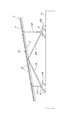
図1〜図3に示す第一実施形態の太陽光発電パネル架台は、左右方向に延びる帯状形態の前部側コンクリート基礎5A上に左右一対の低い前部支柱1A,1Aが、同様の後部側コンクリート基礎5B上に左右一対の高い後部支柱1B,1Bが、それぞれアンカー金具6を介して垂直に立設され、左右一対の受け桟2,2が各々前部支柱1Aと後部支柱1Bに支持されて前後傾斜方向に沿って配置し、両受け桟2,2上に複数枚(図では5枚)の左右方向に長い矩形の太陽光発電パネルPが前後に平面的に配列して取り付けられている。そして、左右の前部支柱1A,1A間には正面ブレース3A,3Aが、左右の後部支柱1B,1B間には背面ブレース3B,3Bが、それぞれX字状に交叉して架設されると共に、左右両側において受け桟2の中間部と前部支柱1Aの下部との間に第1の側面ブレース4Aが、受け桟2の中間部と後部支柱1Bの下部との間に第2の側面ブレース4Bが、それぞれ架設されている。なお、図示の受け桟2の傾斜角度は10°に設定している。   The photovoltaic power generation panel mount according to the first embodiment shown in FIGS. 1 to 3 has a pair of left and right lower front columns 1A, 1A on the front side concrete foundation 5A extending in the left-right direction, and the same rear side. On the concrete foundation 5B, a pair of left and right high rear columns 1B, 1B are erected vertically via anchor fittings 6, respectively, and a pair of left and right receiving bars 2, 2 are supported by the front column 1A and the rear column 1B, respectively. A plurality of (five in the figure) rectangular solar power generation panels P that are long in the left-right direction are mounted on both receiving rails 2 and 2 in a planar arrangement in the front-rear direction. Yes. The front braces 3A and 3A are laid between the left and right front struts 1A and 1A, and the back braces 3B and 3B are respectively erected between the left and right rear struts 1B and 1B. On both the left and right sides, a first side brace 4A is provided between the intermediate part of the receiving bar 2 and the lower part of the front column 1A, and a second side brace 4B is provided between the intermediate part of the receiving bar 2 and the lower part of the rear column 1B. Are built. The inclination angle of the illustrated receiving bar 2 is set to 10 °.

ここで、前部支柱1A及び後部支柱1Bには同一の断面略正方形の中空アルミ型材が、受け桟2には断面略縦長矩形の中空アルミ型材が、正面ブレース3A及び背面ブレース3Bには図4(a)に示すような断面略目の字形の偏平な中空アルミ型材Qが、第1及び第2の側面ブレース4A,4Bには両支柱1A,1Bよりも若干太い断面略正方形の中空アルミ型材が、それぞれ使用されている。   Here, the front support column 1A and the rear support column 1B have the same hollow aluminum mold material having a substantially square cross section, the receiving bar 2 has a substantially vertical rectangular hollow aluminum mold material, and the front brace 3A and the back brace 3B have FIG. A hollow aluminum mold material Q having a substantially square cross section as shown in (a) is a hollow aluminum mold material having a substantially square cross section in the first and second side braces 4A and 4B slightly thicker than both struts 1A and 1B. Are used respectively.

前部側及び後部側コンクリート基礎5A,5Bにおける前部及び後部支柱1A,1Bの立設構造は同じであるため、図4(a)(b)の前部側の図示で代表して説明する。まず、両コンクリート基礎5A,5Bは、その頂面から垂直に穿設した下孔51に、アンカーボルトB1が樹脂系バインダーRを介して一部を上方突出した状態で埋入固着されている。そして、アンカー金具6は、アルミ型材の切断短材からなり、一側半部に前後方向の長孔61を有する水平板部6aの他側半部に、上下方向の長孔62と上部のねじ挿通孔63を有して前後方向に沿う一対の垂直壁部6b,6bが一体に立設されており、コンクリート基礎5A,5Bの頂面に水平板部6aを載置して、その長孔61に通したアンカーボルトB1に平座金W1及びばね座金W2を介してナットN1を螺合緊締することにより、これらコンクリート基礎5A,5Bに該長孔61の範囲で前後方向に位置調整可能に固定されている。   Since the front and rear struts 1A and 1B in the front and rear side concrete foundations 5A and 5B have the same standing structure, they will be described with reference to the front side in FIGS. . First, both concrete foundations 5A and 5B are embedded and fixed in a lower hole 51 vertically drilled from the top surface with an anchor bolt B1 protruding partly upward through a resin binder R. The anchor metal fitting 6 is made of a short cut material of an aluminum mold, and has an elongated hole 62 in the vertical direction and an upper screw in the other half of the horizontal plate portion 6a having a longitudinal hole 61 in the longitudinal direction on one side half. A pair of vertical wall portions 6b, 6b having an insertion hole 63 and extending in the front-rear direction are integrally erected, and a horizontal plate portion 6a is placed on the top surfaces of the concrete foundations 5A, 5B. The nut N1 is screwed and fastened to the anchor bolt B1 passed through 61 through the plain washer W1 and the spring washer W2, so that the position can be adjusted in the longitudinal direction within the range of the long hole 61 to the concrete foundations 5A and 5B. Has been.

前部及び後部支柱1A,1Bは、その下端部に第1又は第2の側面ブレース4A,4Bの後述する下端側の切欠嵌合部43を嵌合した状態で、その嵌合部分をアンカー金具6の垂直壁部6b,6b間に嵌装し、両垂直壁部6b,6bの長孔62,62を通して該嵌合部分に貫通させた取付ボルトB2にナットN2を締着することにより、該長孔62の範囲で上下方向に位置調整可能に固定されると共に、その調整位置において該アンカー金具6の両垂直壁部6b,6bのねじ挿通孔63を通して外側からドリリングタッピングねじSをねじ込むことにより、所定高さに固着されている。なお、取付ボルトB2の頭部側には平座金W1を、ナットN2側には平座金W1及びばね座金W2を介在させているが、これら座金W1,W2の介在は他のボルト止め部分でも同様であるため、以降は説明を省略する。   The front and rear struts 1A and 1B are fitted with anchor fittings at the lower ends of the first and second side braces 4A and 4B. 6 is fitted between the vertical wall portions 6b and 6b, and the nuts N2 are fastened to the mounting bolts B2 passed through the long holes 62 and 62 of the vertical wall portions 6b and 6b. By being fixed so that the position can be adjusted in the vertical direction within the range of the long hole 62, the drilling tapping screw S is screwed from the outside through the screw insertion holes 63 of the vertical wall portions 6b, 6b of the anchor fitting 6 at the adjustment position. It is fixed to a predetermined height. Note that a plain washer W1 is interposed on the head side of the mounting bolt B2, and a plain washer W1 and a spring washer W2 are interposed on the nut N2 side. The interposition of these washers W1 and W2 is the same in other bolting portions. Therefore, the description is omitted hereinafter.

正面ブレース3A及び背面ブレース3Bは、図4(a)(b)の前部側の下部で代表して示すように、各々上下両端部において前部支柱1A又は後部支柱1Bの上下部に対し、その目の字型の断面の中央空間部を通して貫通させた取付ボルトB4とナットN4によって連結している。   The front brace 3A and the back brace 3B, as representatively shown in the lower part on the front side in FIGS. 4 (a) and 4 (b), respectively, on the upper and lower parts of the front strut 1A or the rear strut 1B at both upper and lower ends, It is connected by a mounting bolt B4 and a nut N4 that are passed through the central space portion of the cross section of the eye shape.

前部及び後部支柱1A,1Bの上端側は、図5(a)(b)に示すように、前後対向壁部1a,1aの切除による切欠嵌合部11を有しており、該切欠嵌合部11を受け桟2に下方から跨嵌した嵌合部分を貫通ボルトB3とナットN3でボルト止めすることにより、受け桟2に連結されている。なお、受け桟1は、上面に長手方向に連続する摺動ガイド溝21を備えると共に、両側面2bの上部に長手方向に連続する係止溝22が形成されており、中空内部がやや下方寄り位置の仕切壁23によって上下に区割されている。そして、両支柱1A,1Bの上端側を連結する貫通ボルトB3は、受け桟1の仕切壁23よりも下部側を貫通している。   As shown in FIGS. 5 (a) and 5 (b), the upper ends of the front and rear struts 1A and 1B have notch fitting portions 11 formed by cutting away the front and rear facing wall portions 1a and 1a. The mating portion 11 is connected to the receiving beam 2 by bolting a fitting portion straddling the receiving beam 2 from below with a through bolt B3 and a nut N3. The receiving bar 1 is provided with a sliding guide groove 21 continuous in the longitudinal direction on the upper surface, and a locking groove 22 continuous in the longitudinal direction is formed at the upper part of the both side surfaces 2b. It is divided vertically by the partition wall 23 of the position. And the penetration bolt B3 which connects the upper end side of both support | pillars 1A and 1B has penetrated the lower part side rather than the partition wall 23 of the receiving crosspiece 1. FIG.

第1及び第2の側面ブレース4A,4Bの上端側は、図6(a)(b)に示すように、両支柱1A,1Bの上端側と同様に、切欠嵌合部42を受け桟2に下方から跨嵌した嵌合部分を貫通ボルトB5とナットN5でボルト止めすることにより、該受け桟2の仕切壁23よりも下部側に連結されている。   As shown in FIGS. 6 (a) and 6 (b), the upper end sides of the first and second side braces 4A and 4B receive the notch fitting portions 42 as shown in FIGS. 6 (a) and 6 (b). The fitting part straddled from below is bolted with a through bolt B5 and a nut N5 so as to be connected to the lower side of the partition wall 23 of the receiving bar 2.

図7(a)〜(c)は第1の側面ブレース4A、図8(a)〜(c)は第2の側面ブレース4Bを示す。すなわち、第1及び第2の側面ブレース4A,4Bは、断面略正方形の同じ中空アルミ型材からなり、その内面側の左右方向の対向面に長手方向に連続する突条部41,41を有し、上端側及び下端側に前後対向壁部4a,4aの切除による切欠嵌合部42,43を形成している。このうち、上端側の切欠嵌合部42は両側の左右対向壁部4b,4bの内側に突条部41,41を残すのに対し、下端側の切欠嵌合部43は両側の左右対向壁部4b,4bの突条部41,41まで切除することで開き幅を広くしている。すなわち、上端側の切欠嵌合部42の開き幅は受け桟2の左右幅に対応し、また下端側の切欠嵌合部43の開き幅は前部支柱1A及び後部支柱1Bの左右幅に対応しており、これによって両切欠嵌合部42,43による各々の跨嵌部分にガタつきを生じないようにしている。   7A to 7C show the first side brace 4A, and FIGS. 8A to 8C show the second side brace 4B. That is, the first and second side braces 4A and 4B are made of the same hollow aluminum mold having a substantially square cross section, and have protrusions 41 and 41 that are continuous in the longitudinal direction on opposite surfaces on the inner surface side in the left-right direction. The notch fitting portions 42 and 43 are formed by cutting away the front and rear facing wall portions 4a and 4a on the upper end side and the lower end side. Of these, the notch fitting portion 42 on the upper end side leaves the protrusions 41 and 41 inside the left and right opposing wall portions 4b and 4b on both sides, whereas the notch fitting portion 43 on the lower end side has left and right opposing walls on both sides. The opening width is widened by cutting up the protrusions 41 and 41 of the parts 4b and 4b. That is, the opening width of the notch fitting portion 42 on the upper end side corresponds to the left and right width of the receiving bar 2, and the opening width of the notch fitting portion 43 on the lower end side corresponds to the left and right widths of the front column 1A and the rear column 1B. Thus, rattling is not generated in each straddle portion by the both notch fitting portions 42 and 43.

すなわち、両側面ブレース4A,4Bは下端側の切欠嵌合部43を跨嵌させる両支柱1A,1Bよりも左右幅を大きく(太く)する必要があるが、両支柱1A,1Bも上端側の切欠嵌合部11を受け桟2に跨嵌させるから、各部材の左右幅は両側面ブレース4A,4B>両支柱1A,1B>受け桟2となる。従って、両側面ブレース4A,4Bの上端側の切欠嵌合部42と下端側の切欠嵌合部43が同じ開き幅であれば、下端側の切欠嵌合部43が両支柱1A,1Bに適嵌しても、より左右幅の狭い受け桟2に対して上端側の切欠嵌合部42は隙間を生じてガタつくことになる。一方、突条部41,41のない単なる角筒状のものを用い、下端側の切欠嵌合部43を左右対向壁部4b,4bのみで構成し、上端側の切欠嵌合部42では前後対向壁部4a,4aの両側一部を残す形で開き幅を狭くすることもできるが、この場合は上端側の切欠嵌合部42が跨嵌した受け桟2に対して両側縁部のみで接する形になるから、強固な連結状態にならない。しかるに、実施形態の如く、両側面ブレース4A,4Bの左右対向壁部4b,4bの内側に、両支柱1A,1Bと受け桟2との左右幅の差に相当する高さの突条部41,41を設けることにより、下端側の切欠嵌合部43では両支柱1A,1Bに対して左右対向壁部4b,4bの内面全体で当接させ、上端側の切欠嵌合部42では受け桟2に対して突条部41,41と前後対向壁部4a,4aの両側一部とで当接させ、共に強固な連結状態にすることが可能である。   That is, both side braces 4A and 4B need to be wider (thicker) left and right than both struts 1A and 1B for straddling the notch fitting portion 43 on the lower end side, but both struts 1A and 1B are also on the upper end side. Since the notch fitting portion 11 is fitted over the receiving bar 2, the left and right widths of the respective members are: both side braces 4 </ b> A, 4 </ b> B> both struts 1 </ b> A, 1 </ b> B> receiving bar 2. Therefore, if the notch fitting part 42 on the upper end side and the notch fitting part 43 on the lower end side of the both side braces 4A and 4B have the same opening width, the notch fitting part 43 on the lower end side is suitable for both struts 1A and 1B. Even if fitted, the notch fitting portion 42 on the upper end side with respect to the receiving bar 2 having a narrower left and right width creates a gap and becomes loose. On the other hand, a simple rectangular tube having no protrusions 41, 41 is used, and the notch fitting portion 43 on the lower end side is constituted only by the left and right opposing wall portions 4b, 4b, and the notch fitting portion 42 on the upper end side is front and rear. The opening width can be narrowed by leaving a part of both sides of the opposing wall portions 4a, 4a, but in this case, only the side edge portions on the receiving rail 2 with the notch fitting portion 42 on the upper end side straddled. Since it comes in contact, it will not be in a strong connected state. However, as in the embodiment, on the inner side of the left and right opposing wall portions 4b and 4b of the both side braces 4A and 4B, the ridge portion 41 having a height corresponding to the difference between the left and right widths of the two columns 1A and 1B and the receiving bar 2 is provided. , 41, the notch fitting part 43 on the lower end side is brought into contact with both struts 1A, 1B on the entire inner surfaces of the left and right opposing wall parts 4b, 4b, and the receiving bar is provided on the notch fitting part 42 on the upper end side. 2 can be brought into contact with the protrusions 41 and 41 and part of both sides of the front and rear opposing wall portions 4a and 4a, and both can be brought into a firm connection state.

なお、第1の側面ブレース4Aと第2の側面ブレース4Bとでは、受け桟2及び両支柱1A,1Bに対する配位角度が同じでないため、両切欠嵌合部42,43の深さと底側の傾きが図7及び図8で示すように異なっている。また、両側面ブレース4A,4Bの上端側の切欠嵌合部42には径小のボルト挿通孔45が、下端側の切欠嵌合部43には径大のボルト挿通孔46が、それぞれ穿設されている。   Note that the first side brace 4A and the second side brace 4B have the same alignment angle with respect to the receiving bar 2 and both struts 1A and 1B. The inclination is different as shown in FIGS. Further, a small-diameter bolt insertion hole 45 is formed in the notch fitting portion 42 on the upper end side of the braces 4A and 4B on both sides, and a large-diameter bolt insertion hole 46 is provided in the notch fitting portion 43 on the lower end side. Has been.

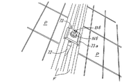
図9で詳細に示すように、各太陽光発電パネルPは、矩形の縁枠Fの内側に太陽電池モジュールMを嵌装したものであり、受け桟2の上面の摺動ガイド溝21に嵌挿されたスライド金具71と、該スライド金具71を下方から貫通する止着用ボルトB6と、該止着用ボルトB6に嵌挿したスペーサー金具72と、該止着用ボルトB6に螺着するナットN6とによって、受け桟2に固定されている。そして、受け桟2は、太陽光発電パネルPの前後配列の全長を少し越える長さを有し、図10(a)(b)に示すように、摺動ガイド溝21は、その両側の内側面に縦断面L字形に凹入する係合溝部21a,21aを有しており、これら係合溝部21a,21aの位置で奥広になっている。   As shown in detail in FIG. 9, each photovoltaic power generation panel P has a solar cell module M fitted inside a rectangular edge frame F, and is fitted in a sliding guide groove 21 on the upper surface of the receiving bar 2. An inserted slide fitting 71, a fastening bolt B6 penetrating the slide fitting 71 from below, a spacer fitting 72 inserted into the fastening bolt B6, and a nut N6 screwed to the fastening bolt B6 , Fixed to the receiving bar 2. The receiving bar 2 has a length slightly exceeding the total length of the front and rear array of the photovoltaic power generation panels P. As shown in FIGS. 10 (a) and 10 (b), the sliding guide grooves 21 are formed on the inner sides of both sides. Engaging groove portions 21a and 21a that are recessed in a vertical cross-section L-shape are provided on the side surfaces, and are deep at the positions of these engaging groove portions 21a and 21a.

スライド金具71は、アルミ押出型材の切断短材からなり、図10(a)にて詳細に示すように、摺動方向に長い帯板状で厚肉の基板部71aの下面側に平行する2条の脚片部71b,71bが突設されると共に、該基板部71aの幅方向両側に縦断面L字形の係合条片部71c,71cが張設されており、該基板部71aの中央部には上下に透通するボルト挿通孔71dを備えている。そして、このスライド金具71は、受け桟2の摺動ガイド溝21に対して一端側から挿嵌することにより、両係合条片部71c,71cが係合溝部21a,21aに係合するため、該受け桟2の長手方向に摺動自在で且つ上方離脱不能に保持される。なお、この挿嵌状態において、スライド金具71の基板部71aの上面が受け桟2の上端と略同じ高さで、両脚片部71b,71bが摺動ガイド溝21の内底に略接するように寸法設定されている。   The slide fitting 71 is made of a short cut material of an aluminum extrusion mold material, and as shown in detail in FIG. 10 (a), is parallel to the lower surface side of the thick substrate portion 71a which is long in the sliding direction. The leg piece portions 71b and 71b of the strip project, and the engagement strip portions 71c and 71c having an L-shaped longitudinal section are stretched on both sides in the width direction of the substrate portion 71a. The part is provided with a bolt insertion hole 71d that is vertically permeable. The slide fitting 71 is inserted into the slide guide groove 21 of the receiving bar 2 from one end side so that both the engagement strip portions 71c and 71c are engaged with the engagement groove portions 21a and 21a. The receiving bar 2 is slidable in the longitudinal direction and is held so as not to be separated upward. In this insertion state, the upper surface of the substrate portion 71 a of the slide fitting 71 is substantially the same height as the upper end of the receiving bar 2, and the both leg piece portions 71 b and 71 b are substantially in contact with the inner bottom of the sliding guide groove 21. The dimensions are set.

止着用ボルトB6は、一般的な六角ボルトであって、スライド金具71のボルト挿通孔71dに下方から挿通させることにより、その六角形の頭部B6aが該スライド金具71の両脚片部71b,71b間に回転不能に収まるように設定されている。   The fixing bolt B6 is a general hexagon bolt, and the hexagonal head B6a is inserted into the bolt insertion hole 71d of the slide fitting 71 from below so that the leg piece portions 71b and 71b of the slide fitting 71 are fixed. It is set so that it can not rotate in between.

押さえ金具73は、図9及び図12に示すように、受け桟2の前後方向の中間部において太陽光発電パネルPを固定するのに使用されるものであり、略正方形板状のアルミ押出型材の切断短材からなり、両側縁に縦断面逆L字状の係合片73aを備えている。また、端部押さえ金具9は、図9及び図12に示すように、受け桟2の前後両端部において太陽光発電パネルPの端部を固定するのに使用されるものであり、押さえ金具73と同様にアルミ押出型材の切断短材からなり、矩形の基板部90の一側側縁に縦断面逆L字状の係合片90aを備えるが、該基板部90の他側側縁には縦断面日の字形の側方カバー部91が垂設されている。なお、図示を省略しているが、押さえ金具73及び端部押さえ金具9にはボルト挿通孔が穿設されている。   As shown in FIGS. 9 and 12, the holding metal fitting 73 is used to fix the photovoltaic power generation panel P at the intermediate portion in the front-rear direction of the receiving bar 2, and is a substantially square plate-shaped aluminum extrusion mold material. It is made of a short cut material and is provided with engaging pieces 73a having a reverse L-shaped longitudinal section on both side edges. Further, as shown in FIGS. 9 and 12, the end pressing metal fitting 9 is used to fix the end portions of the photovoltaic power generation panel P at the front and rear end portions of the receiving bar 2. In the same manner as above, it is made of a short cut material of an aluminum extrusion mold material, and includes an engagement piece 90a having a vertical L-shaped cross section on one side edge of the rectangular substrate part 90, but on the other side edge of the substrate part 90 A side cover portion 91 having a vertical cross-sectional shape is suspended. In addition, although illustration is abbreviate | omitted, the bolt insertion hole is drilled in the presser metal fitting 73 and the edge part presser metal fitting 9.

スペーサー金具72は、下向き開放コ字枠状のアルミ押出型材の切断短材からなり、図10(a)(b)に示すように、その上板部72aにボルト挿通孔72eを有すると共に、両側片部72b,72bには下端で内向き突出する係止爪72cと中間部で内向き突出する突片72dが形成されている。このスペーサー金具72は、両係止爪72c,72cを受け桟2の両側の係止溝22,22に係合すると共に、両突片72d,72dが該受け桟2の上面2a,2aに載る形で、該受け桟2に上方離脱不能にスライド嵌合し得るように設定されている。   The spacer metal fitting 72 is made of a short cut material of an aluminum extrusion mold material having a downwardly open U-shaped frame shape, and has a bolt insertion hole 72e in the upper plate portion 72a as shown in FIGS. A locking claw 72c that protrudes inward at the lower end and a protruding piece 72d that protrudes inward at the middle are formed on the pieces 72b and 72b. The spacer metal 72 is engaged with the locking grooves 22 and 22 on both sides of the receiving bar 2 while the both locking claws 72c and 72c are received, and both protruding pieces 72d and 72d are placed on the upper surfaces 2a and 2a of the receiving bar 2. In this manner, the receiving bar 2 is set so as to be slidably fitted so as not to be separated upward.

図10(b)に示すように、スライド金具71と止着用ボルトB5及びスペーサー金具72は、スライド金具71とその上側に配置させたスペーサー金具71の両ボルト挿通孔71d,72eに下方から止着用ボルトB6を貫通させた状態で、スライド金具71を受け桟2の摺動ガイド溝21へ挿嵌すると同時にスペーサー金具72を受け桟2にスライド嵌合させる。これにより、スライド金具71から止着用ボルトB6が直立した状態で安定に保たれると共に、スペーサー金具72の上板部72aも縦桟1から一定の高さに安定的に保持される。   As shown in FIG. 10 (b), the slide fitting 71, the fastening bolt B5, and the spacer fitting 72 are fastened from below to the slide fitting 71 and both bolt insertion holes 71d and 72e of the spacer fitting 71 arranged on the upper side thereof. In a state where the bolt B6 is penetrated, the slide fitting 71 is inserted into the sliding guide groove 21 of the receiving beam 2 and at the same time, the spacer fitting 72 is slid into the receiving beam 2. As a result, the fastening bolt B6 is stably held upright from the slide fitting 71, and the upper plate portion 72a of the spacer fitting 72 is also stably held at a constant height from the vertical rail 1.

一方、前方に低く傾斜した受け桟2の前端部では、図9及び図12に示すように、その摺動ガイド溝21の前端の底面に、L字形に曲折した金属板からなるストッパー部材8がドリリングタッピングねじSによって固着されている。これにより、該摺動ガイド溝21に嵌挿したスライド金具71は、その脚片部71bがストッパー部材8に当接することで、該摺動ガイド溝21から前方への抜落が阻止されている。   On the other hand, as shown in FIGS. 9 and 12, at the front end portion of the receiving bar 2 inclined to the front, a stopper member 8 made of a metal plate bent in an L shape is formed on the bottom surface of the front end of the sliding guide groove 21. It is fixed by a drilling tapping screw S. As a result, the slide fitting 71 fitted in the slide guide groove 21 is prevented from dropping forward from the slide guide groove 21 by the leg piece portion 71b coming into contact with the stopper member 8. .

受け桟2上に太陽光発電パネルPを取り付けるには、各受け桟2の摺動ガイド溝21に、上述のように止着用ボルトB6及びスペーサー金具72を組み付けたスライド金具71の所要個数、つまり前後配列させる太陽光発電パネルPの枚数プラス1個(図1,図2の如く太陽光発電パネルPの枚数が5枚の場合は6個)を挿嵌させておき、この受け桟2上に所要枚数の太陽光発電パネルPを前列側から順次に、前後端及び相互間にスライド金具21を介在させながら載せてゆく。このとき、受け桟2の摺動ガイド溝21に挿嵌した最前端のスライド金具71がストッパー部材8に接当した状態で停止するから、複数枚の太陽光発電パネルPを該受け桟2の傾斜に沿って滑らせて前方へ詰めてゆく形で能率よく配列させることができる。   In order to mount the photovoltaic power generation panel P on the receiving bar 2, the required number of the slide fittings 71 in which the fixing bolts B <b> 6 and the spacer fittings 72 are assembled in the sliding guide grooves 21 of the receiving bars 2 as described above, that is, The number of photovoltaic power generation panels P to be arranged in the front-rear direction plus one (six if the number of photovoltaic power generation panels P is five as shown in FIGS. 1 and 2) is inserted and placed on the receiving rail 2 The required number of photovoltaic power generation panels P are sequentially placed from the front row side with the slide fittings 21 interposed between the front and rear ends and each other. At this time, since the slide fitting 71 at the foremost end inserted into the sliding guide groove 21 of the receiving bar 2 stops in contact with the stopper member 8, a plurality of photovoltaic panels P are attached to the receiving bar 2. It can be arranged efficiently by sliding along the slope and packing it forward.

そして、図9に示すように、受け桟2の中間部では、前後に隣接する太陽光発電パネルP,Pの縁枠F,Fの対向側面をスライド金具71に組み付けたスペーサー金具72に当接させた状態で、該スライド金具71から突出する止着用ボルトB6に押さえ金具73を嵌装し、該押さえ金具73の両係合片73a,73aが各々両側の縁枠F,Fの内側に配置する状態で、止着用ボルトB6に平座金W1及びばね座金W2を介してナットN6を螺合して締め付けることにより、押さえ金具73と受け桟2との間で両太陽光発電パネルP,Pの縁枠F,Fを挟着固定する。また同様に、該受け桟2の前後端部では、端部位置の太陽光発電パネルPの縁枠Fの前側面又は後側面をスペーサー金具72に当接させた状態で、止着用ボルトB6に端部押さえ金具9を係合片90a側が太陽光発電パネルP側に向くように嵌装し、その上から止着用ボルトB6にナットN6を螺合して締め付けることにより、押さえ金具9と受け桟2との間で両太陽光発電パネルPの縁枠Fを挟着固定する。なお、この前後端部では、図9及び図12に示すように、押さえ金具9の側方カバー部91によって止着用ボルトB6の軸部及びスペーサー金具72が側方から隠されることで、太陽光発電パネル架台の前後の外観が良くなっている。   Then, as shown in FIG. 9, in the middle portion of the receiving bar 2, the opposite side surfaces of the edge frames F, F of the photovoltaic power generation panels P, P adjacent to the front and rear abut against the spacer metal fitting 72 assembled to the slide metal fitting 71. In this state, the holding metal fitting 73 is fitted to the fastening bolt B6 protruding from the slide metal fitting 71, and both engaging pieces 73a, 73a of the holding metal fitting 73 are arranged inside the edge frames F, F on both sides, respectively. In this state, the nuts N6 are screwed and tightened to the fastening bolts B6 via the plain washers W1 and the spring washers W2, so that the solar panels P, P can be connected between the presser fitting 73 and the receiving bar 2. The edge frames F and F are clamped and fixed. Similarly, at the front and rear ends of the receiving bar 2, the fastening bolt B 6 is attached to the fastening bolt B 6 with the front side surface or rear side surface of the edge frame F of the photovoltaic power generation panel P at the end position in contact with the spacer metal fitting 72. The end holding metal fitting 9 is fitted so that the engaging piece 90a side faces the photovoltaic power generation panel P side, and a nut N6 is screwed onto the fastening bolt B6 from above and tightened, whereby the holding metal fitting 9 and the receiving bar are attached. The edge frame F of both photovoltaic power generation panels P is clamped and fixed between the two. In addition, in this front-and-rear end part, as shown in FIG.9 and FIG.12, the shaft part of the fixing bolt B6 and the spacer metal fitting 72 are concealed from the side by the side cover part 91 of the presser fitting 9, thereby The front and rear appearances of the power generation panel mount are improved.

上記構成の太陽光発電パネル架台では、複数枚の太陽光発電パネルPを前後傾斜方向に沿う左右一対の受け桟2,2にて支承し、各受け桟2を前部支柱1Aと後部支柱1Bとで支持するから、その組立施工に際し、従来の格子状の受けフレームのように縦桟と横桟とを各交叉部で連結する必要がなく、その連結のための多大な手間及び時間が省かれ、施工能率が飛躍的に向上する。また、格子状の受けフレームを用いる場合に比して架台上部側が大幅に軽量化することに加え、この軽量化によって前部支柱1A及び後部支柱1Bとして比較的に支持強度の小さい細いものを使用できるから、架台全体として更に軽量化すると共に、格子状の受けフレームにおける横桟及び連結金具の省略と相俟って部材コストも著しく低減される。一方、太陽光発電パネル架台としての構体強度は、前部支柱1A,1A間及び後部支柱1B,1B間にX字状に交叉して架設される正面ブレース3A,3A及び背面ブレース3B,3B、ならびに左右両側における受け桟2の中間部と前部支柱1A及び後部支柱1Bの下部との間に架設される側面ブレース4A,4Bにより、4本の支柱1A,1A,1B,1Bと左右の受け桟2,2が相互に強固に繋がって一体化するから、太陽光発電パネルPを左右の受け桟2,2のみで支承することによる低下分の補完を越えて大きく向上し、風圧や地震動に対する充分な耐性が得られる。   In the photovoltaic panel base having the above-described configuration, a plurality of photovoltaic panels P are supported by a pair of left and right receiving bars 2 and 2 along the front-rear tilt direction, and each receiving bar 2 is supported by a front column 1A and a rear column 1B. Therefore, it is not necessary to connect the vertical beam and the horizontal beam at each crossing portion as in the conventional grid-shaped receiving frame during assembly work, and a great amount of labor and time for the connection can be saved. As a result, construction efficiency is dramatically improved. In addition to significantly reducing the weight of the upper part of the gantry compared to the case of using a lattice-shaped receiving frame, the weight of the front column 1A and the rear column 1B are relatively thin with relatively low support strength. Therefore, the overall weight of the gantry can be further reduced, and the cost of the members can be significantly reduced in combination with the omission of the cross rail and the connecting bracket in the lattice-shaped receiving frame. On the other hand, the strength of the structure as a photovoltaic power generation panel mount is such that the front braces 3A, 3A and the back braces 3B, 3B are constructed by crossing in an X shape between the front struts 1A, 1A and between the rear struts 1B, 1B. In addition, four support pillars 1A, 1A, 1B, 1B and left and right supports are provided by side braces 4A, 4B installed between the middle part of the receiving bar 2 on the left and right sides and the lower part of the front support post 1A and the rear support post 1B. Since the piers 2 and 2 are firmly connected to each other and integrated, the solar power generation panel P is greatly improved by overcoming the decrease due to being supported only by the left and right receiving piers 2 and 2, and against wind pressure and earthquake motion. Sufficient tolerance is obtained.

特に実施形態の構成では、前部支柱1A及び後部支柱1Bと受け桟2が断面略矩形のアルミ型材からなるため、架台全体がより軽量で且つ高強度になる上、前部支柱1A及び後部支柱1Bは上端側の切欠嵌合部11を受け桟2に下方から跨嵌して、その嵌合部分をボルト止めで連結するから、両支柱1A,1Bと受け桟2との連結を容易に迅速に行え、もって施工能率がより向上すると共に、連結金具を用いないことで部材コストもより低減されるという利点がある。また、前部支柱1A及び後部支柱1Bはコンクリート基礎5A,5B上にアンカー金具6を介して立設されるが、特に実施形態で用いたアンカー金具6によれば、コンクリート基礎5A,5Bに対して水平板部6aの長孔61の範囲で前後方向に位置調整できると共に、両支柱1A,1Bの高さを該アンカー金具6の垂直壁部6b,6bの長孔62の範囲で調整できるから、太陽光発電パネルPの据付位置や仰角を精度よく設定できると共に、施工後の地盤沈下等に対応した位置及びパネル角度の修正も容易に行えるという利点がある。   In particular, in the configuration of the embodiment, since the front column 1A, the rear column 1B, and the receiving bar 2 are made of an aluminum mold having a substantially rectangular cross section, the entire gantry is lighter and stronger, and the front column 1A and the rear column 1B has a notch fitting portion 11 on the upper end side and is fitted over the crosspiece 2 from below, and the fitting portion is connected with a bolt, so that the connection between the support posts 1A, 1B and the reception crosspiece 2 can be easily and quickly performed. Therefore, there is an advantage that the construction efficiency is further improved, and the member cost is further reduced by not using the connecting metal fitting. In addition, the front support column 1A and the rear support column 1B are erected on the concrete foundations 5A and 5B via the anchor fittings 6. In particular, according to the anchor fittings 6 used in the embodiment, the concrete foundations 5A and 5B As a result, it is possible to adjust the position in the front-rear direction within the range of the long hole 61 of the horizontal plate portion 6a, and to adjust the height of both struts 1A, 1B within the range of the long hole 62 of the vertical wall portions 6b, 6b of the anchor fitting 6. There is an advantage that the installation position and elevation angle of the photovoltaic power generation panel P can be set with high accuracy, and the position and panel angle corresponding to the ground subsidence after construction can be easily corrected.

一方、架台の基礎側については、各支柱毎に独立した置き基礎型のコンクリートブロックを用いることもできるが、上記実施形態のように前部側及び後部側において各々左右方向に延びる帯状に形成されたコンクリート基礎5A,5Bを採用すれば、前部側コンクリート基礎5A上に前部支柱1A,1Aを立設し、後部側のコンクリート基礎5B上に後部支柱1B,1Bを立設することで、架台の前後位置及び向きが自ずと定まり、それだけ施工が容易になると共に、基礎側が大重量で変位する懸念がないために架台の安定性も増し、特にメガソーラーやギガソーラーとして同じ太陽光発電パネル架台の複数基を左右に並設する場合に全体の位置と向きを揃え易いという利点がある。   On the other hand, on the foundation side of the gantry, an independent foundation-type concrete block can be used for each column, but it is formed in a strip shape extending in the left-right direction on the front side and the rear side as in the above embodiment. If the concrete foundations 5A and 5B are employed, the front struts 1A and 1A are erected on the front concrete foundation 5A, and the rear struts 1B and 1B are erected on the rear concrete foundation 5B. The front / rear position and orientation of the pedestal are naturally determined, and the installation is easier, and there is no concern of the foundation side being displaced by heavy weight, so the stability of the pedestal also increases. Especially, the same photovoltaic panel gantry as mega solar or giga solar There is an advantage that it is easy to align the whole position and orientation when arranging a plurality of these in parallel.

また、第1及び第2の側面ブレース4A,4Bについては、正面ブレース3Aや背面ブレース3Bと同様に偏平な中空アルミ型材を用いてもよいが、本発明の太陽光発電パネル架台では概して前後方向に長い形態になるから、その長手方向の補強効果を高める上で、実施形態のような断面略正方形で、且つ上端側及び下端側の切欠嵌合部42,43で受け桟2及び両支柱1A,1Bに跨嵌し得るもの、つまり左右幅が両支柱1A,1Bより大きいものを用いることが好ましい。そして、実施形態のように、上端側及び下端側の切欠嵌合部42,43で受け桟2及び両支柱1A,1Bに跨嵌して、その嵌合部分でボルト止めするようにすれば、その連結操作を容易に能率よく行える。更に、実施形態のように、下端側の切欠嵌合部43を、その跨嵌した前部支柱1A又は後部支柱1Bと一体にアンカー金具6を介してボルト止めする構造とすれば、組立施工の能率がより向上するという利点がある。   Further, as for the first and second side braces 4A and 4B, a flat hollow aluminum mold material may be used as in the case of the front brace 3A and the back brace 3B. In order to enhance the reinforcing effect in the longitudinal direction, the receiving bar 2 and both struts 1A are formed by the cut-off fitting portions 42 and 43 on the upper end side and the lower end side in order to enhance the longitudinal reinforcing effect. , 1B, that is, it is preferable to use one having a lateral width larger than both struts 1A, 1B. And, as in the embodiment, if it is straddled on the receiving bar 2 and both struts 1A, 1B at the notch fitting portions 42, 43 on the upper end side and the lower end side, and bolted at the fitting portion, The connecting operation can be performed easily and efficiently. Further, as in the embodiment, if the notch fitting portion 43 on the lower end side is bolted to the strut 1A or the rear strut 1B integrally with the anchor bracket 6 via an anchor fitting 6, There is an advantage that the efficiency is further improved.

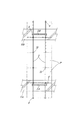
なお、前記の第一実施形態では左右の各側で第1及び第2の2本の側面ブレース4A,4Bを用いているが、太陽光発電パネルPの配設枚数が多い場合等で受け桟2の全長を長くするとき、該受け桟2の前方張出部と前部支柱1Aとの間や、該受け桟2の後方張出部と後部支柱1Bとの間に、更に側面ブレースを追加架設してもよい。例えば、図13で示す第二実施形態の太陽光発電パネル架台では、6枚の太陽光発電パネルPを前後に配列するために受け桟2の前部側が前部支柱1Aによる支持部よりも前方へ長く張出しており、その張出部20と前部支柱1Aの下部との間に、第1及び第2の側面ブレース4A,4Bと同じ断面略正方形の中空アルミ型材からなる第3の側面ブレース4Cを架設しており、これによって充分な構体強度を確保している。なお、この第3の側面ブレース4Cの上端側及び下端側は、詳細な図示を省略しているが、第1及び第2の側面ブレース4A,4Bと同様の切欠嵌合部として、受け桟2及び前部支柱1Aに跨嵌してボルト止めするものである。   In the first embodiment, the first and second side braces 4A and 4B are used on each of the left and right sides. When the overall length of 2 is increased, a side brace is further added between the front overhanging portion of the receiving beam 2 and the front column 1A, and between the rear protruding portion of the receiving beam 2 and the rear column 1B. It may be erected. For example, in the photovoltaic power generation panel stand of the second embodiment shown in FIG. 13, the front side of the receiving bar 2 is ahead of the support portion by the front support column 1A in order to arrange the six photovoltaic power generation panels P back and forth. A third side brace made of a hollow aluminum mold having a substantially square cross section similar to that of the first and second side braces 4A and 4B, between the overhang portion 20 and the lower portion of the front column 1A. 4C is installed, and this ensures sufficient structural strength. Although the detailed illustration of the upper end side and the lower end side of the third side brace 4C is omitted, the receiving bar 2 is used as a notch fitting portion similar to the first and second side braces 4A and 4B. And it bolts by straddling the front support column 1A.

一方、実施形態の構成では、受け桟2,2上に太陽光発電パネルPを取り付ける際、該受け桟2の摺動ガイド溝21に、下方から止着用ボルトB6を貫通させたスライド金具71を嵌挿し、この受け際2上に前後の太陽光発電パネルP,P同士を止着用ボルトB6を挟むように載せ、該止着用ボルトB6に嵌め込んだ押さえ金具73を両太陽光発電パネルP,Pの縁枠F,F間に橋架し、上から止着用ボルトB6にナットN6を螺合緊締すればよいから、各太陽光発電パネルPを簡単な操作で能率よく固定できる。しかも、その固定強度が大きく、例えば太陽光発電パネルPに地震時の大きな揺れや強風時の大きな風圧が作用しても、その負荷がスライド金具71を介して摺動ガイド溝21の両側縁部21a,21aで受け止められ、該スライド金具71が摺動ガイド溝21から外れたり、止着用ボルトB6が捩じ切れたり曲がったりする懸念がない。また、スライド金具71が止着用ボルトB6に対するナットN6の未螺合又は弛緩状態で摺動ガイド溝21に沿って移動可能であるから、受け桟2上に載せた各太陽光発電パネルPを前後に位置決めした上で該ナットN6を螺合緊締することで、太陽光発電パネルPの全体の配置を高精度に設定できるという利点がある。   On the other hand, in the configuration of the embodiment, when the photovoltaic power generation panel P is mounted on the receiving rails 2 and 2, the slide fitting 71 in which the fastening bolt B <b> 6 is penetrated from below into the sliding guide groove 21 of the receiving rail 2. Inserting and placing the front and rear photovoltaic panels P, P on the receiving side 2 with the fastening bolts B6 sandwiched between them, the holding metal fittings 73 fitted into the fastening bolts B6 are mounted on the two photovoltaic panels P, Since it is only necessary to bridge between the edge frames F and F of P and to fasten and fasten the nut N6 to the fastening bolt B6 from above, each photovoltaic power generation panel P can be efficiently fixed by a simple operation. Moreover, even if the fixed strength is large, for example, even when the solar power generation panel P is subjected to a large shaking during an earthquake or a large wind pressure during a strong wind, the load is applied to both side edges of the sliding guide groove 21 via the slide fitting 71. There is no concern that the slide fitting 71 is detached from the slide guide groove 21 and the fastening bolt B6 is twisted or bent. Further, since the slide fitting 71 can move along the sliding guide groove 21 when the nut N6 is not screwed or loosened with respect to the fastening bolt B6, each photovoltaic power generation panel P placed on the receiving bar 2 is moved back and forth. By positioning the nut N6 and tightening the nut N6, there is an advantage that the entire arrangement of the photovoltaic power generation panel P can be set with high accuracy.

更に、実施形態のように、前方に低く傾斜した受け桟2の摺動ガイド溝21の前端部に、スライド金具71の抜出を阻止するストッパー部材8を止着する構成とすれば、太陽光発電パネルPの取り付けに際し、各スライド金具71が止着用ボルトB6に対するナットN6の未螺合又は弛緩状態のまま、複数枚の太陽光発電パネルPを前位置のものから順次に、前端及び相互間にスライド金具71を介在させながら該受け桟2上に載せ、その傾斜に沿って滑らせて前方へ詰めてゆく形で能率よく配列させることができる。また、実施形態のように止着用ボルトB6にスペーサー金具72を嵌装することにより、該スペーサー金具72を隣接配置する太陽光発電パネルP,Pの間で挟み付けて位置決めできるから、受け桟2上での各太陽光発電パネルPの位置設定をより容易に精密に行える。   Furthermore, if it is set as the structure which fastens the stopper member 8 which prevents extraction of the slide metal fitting 71 to the front-end part of the sliding guide groove 21 of the receiving rail 2 inclined low like the front like Embodiment, it is sunlight. When the power generation panel P is attached, the plurality of photovoltaic power generation panels P are sequentially moved from the front position to the front end and between each slide fitting 71 while the nut N6 is not screwed or loosened with respect to the fixing bolt B6. It can be efficiently arranged in such a manner that it is placed on the receiving bar 2 with the slide fitting 71 interposed therebetween, and is slid along the inclination and packed forward. In addition, since the spacer metal fitting 72 is fitted to the fastening bolt B6 as in the embodiment, the spacer metal fitting 72 can be sandwiched and positioned between the adjacent photovoltaic power generation panels P and P. The position of each photovoltaic power generation panel P can be set more easily and accurately.

本発明の太陽光発電パネル架台における受け桟2の傾斜角度は、前記実施形態で例示した10°に限らず、設置場所の周辺状況や緯度による受光効率等を勘案して適宜設定すればよい。更に、本発明においては、前部及び後部支柱1A,1B、受け桟2、正面及び背面ブレース3A,3B、第1〜第3の側面ブレース4A〜4Cの各々の断面形状、アンカー金具6の形状、スライド金具71、押さえ金具73、端部押さえ金具9の形態、太陽光発電パネルPの形状と配列枚数等、細部構成については実施形態以外に種々設計変更可能である。   The inclination angle of the receiving bar 2 in the photovoltaic power generation panel mount of the present invention is not limited to 10 ° exemplified in the above embodiment, and may be set as appropriate in consideration of the surrounding conditions of the installation location, the light receiving efficiency depending on the latitude, and the like. Furthermore, in the present invention, the cross-sectional shapes of the front and rear struts 1A and 1B, the receiving bar 2, the front and back braces 3A and 3B, the first to third side braces 4A to 4C, and the shape of the anchor fitting 6 In addition to the embodiment, various modifications can be made to the detailed configuration such as the shape of the slide fitting 71, the holding fitting 73, the end holding fitting 9, the shape and the number of the photovoltaic power generation panels P, and the like.

1A 前部支柱
1B 後部支柱
1a 前後対向壁部
11 切欠嵌合部
2 受け桟
2a 上面
20 張出部
21 摺動ガイド溝
3A 正面ブレース
3B 背面ブレース
4A 第1の側面ブレース
4B 第2の側面ブレース
4C 第3の側面ブレース
4a 前後対向壁部
4b 左右対向壁部
41 突条部
42,43 切欠嵌合部
5A 前部側コンクリート基礎
5B 後部側コンクリート基礎
6 アンカー金具
6a 水平板部
6b 垂直壁部
61,62 長孔
71 スライド金具
72 スペーサー金具
73 押さえ金具
8 ストッパー部材゛
9 端部押さえ金具
B1 アンカーボルト
B2 取付ボルト
B6 止着用ボルト
F 縁枠
M 太陽電池モジュール
N1〜N6 ナット
P 太陽光発電パネル
DESCRIPTION OF SYMBOLS 1A Front support | pillar 1B Rear support | pillar 1a Front and rear opposing wall part 11 Notch fitting part 2 Receiving bar 2a Upper surface 20 Overhang | projection part 21 Sliding guide groove 3A Front brace 3B Rear brace 4A 1st side brace 4B 2nd side brace 4C Third side brace 4a Front and rear facing walls 4b Left and right facing walls 41 Projection sections 42, 43 Notch fitting section 5A Front side concrete foundation 5B Rear side concrete foundation 6 Anchor metal fitting 6a Horizontal flat section 6b Vertical wall section 61, 62 Long hole 71 Slide bracket 72 Spacer bracket 73 Presser bracket 8 Stopper member 9 End clamp bracket B1 Anchor bolt B2 Mounting bolt B6 Fastening bolt F Edge frame
M Solar cell module N1-N6 Nut P Solar power generation panel

Claims (6)

低位側の左右一対の前部支柱と、高位側の左右一対の後部支柱と、各々前部支柱及び後部支柱に支持されて前後傾斜方向に沿って配置した左右一対の受け桟と、両受け桟上に前後に配列して取り付けられた複数枚の太陽光発電パネルとを備え、
左右の前部支柱間には2本の正面ブレースが、左右の後部支柱間には2本の背面ブレースが、それぞれX字状に交叉して架設され、
各受け桟の中間部と前部支柱の下部との間に第1の側面ブレースが架設されると共に、該受け桟の中間部と後部支柱の下部との間に第2の側面ブレースが架設されてなり、
前部支柱及び後部支柱と受け桟が断面略矩形の中空アルミ型材からなり、前部支柱及び後部支柱の上端側に前後対向壁部の切除による切欠嵌合部が形成され、該切欠嵌合部を受け桟に下方から跨嵌した嵌合部分をボルト止めすることにより、前部支柱及び後部支柱と受け桟とが連結されてなり、
前記受け桟の前部側が前部支柱による支持部よりも前方へ長く張出し、その張出部と前部支柱の下部との間に第3の側面ブレースが架設されてなり、
且つ、前記の各側面ブレースは、断面略矩形の中空アルミ型材からなり、その内面側の左右方向の対向面に長手方向に連続する突条部が形成され、上端側及び下端側に前後対向壁部の切除による切欠嵌合部を備え、左右対向壁部に前記突条部を有する上端側の切欠嵌合部を受け桟に下方から跨嵌する一方、左右対向壁部の該突条部の切除によって開き幅を広くした下端側の切欠嵌合部を前部支柱又は後部支柱に跨嵌し、これら嵌合部分でボルト止めしてなる太陽光発電パネル架台。
A pair of left and right front struts on the lower side, a pair of left and right rear struts on the high side, a pair of left and right receiving bars supported by the front and rear struts and arranged along the front-rear tilt direction, and both receiving bars With a plurality of photovoltaic panels mounted on the front and back,
There are two front braces between the left and right front struts, and two back braces between the left and right rear struts.
A first side brace is installed between the intermediate part of each receiving bar and the lower part of the front column, and a second side brace is installed between the intermediate part of the receiving bar and the lower part of the rear column. Do Te Ri,
The front strut, the rear strut, and the receiving bar are made of a hollow aluminum mold having a substantially rectangular cross section, and a notch fitting portion is formed on the upper end side of the front strut and the rear strut by cutting the front and rear facing wall portions. By bolting the fitting part straddling from the lower side to the receiving bar, the front column and the rear column and the receiving frame are connected,
The front side of the receiving bar extends longer than the support portion by the front column, and a third side brace is constructed between the protruding portion and the lower portion of the front column,
Each of the side braces is made of a hollow aluminum mold having a substantially rectangular cross section, and is formed with protrusions continuous in the longitudinal direction on the opposing surface in the left-right direction on the inner surface side, and front and rear opposing walls on the upper end side and the lower end side. A notch fitting part by cutting off the part, and a notch fitting part on the upper end side having the protruding part on the left and right opposing wall part is straddled from below to the crosspiece, while the protruding part of the right and left opposing wall part is A photovoltaic power generation panel gantry in which a notch fitting portion on the lower end side widened by excision is fitted over a front support column or a rear support column and bolted at these fitting portions .
前部支柱及び後部支柱がコンクリート基礎上にアンカー金具を介して立設され、
該アンカー金具は、前後方向の長孔を有する水平板部と、上下方向の長孔を有する垂直壁部とを有し、水平板部においてコンクリート基礎の頂面から突出したアンカーボルトを長孔に通してナットで締付固定すると共に、垂直壁部において長孔を通して前部及び後部支柱の下端部に貫通させた取付ボルトにナットを締付固定するように構成されてなる請求項に記載の太陽光発電パネル架台。
Front struts and rear struts are erected on the concrete foundation via anchor fittings,
The anchor metal fitting has a horizontal plate portion having a long hole in the front-rear direction and a vertical wall portion having a long hole in the vertical direction, and the anchor bolt protruding from the top surface of the concrete foundation in the horizontal plate portion is made into a long hole. 2. The nut according to claim 1 , wherein the nut is fastened and fixed with a nut, and the nut is fastened and fixed to a mounting bolt that penetrates through the long hole in the vertical wall portion and penetrates the lower end portion of the front and rear columns. Solar power panel mount.
前記コンクリート基礎が前部側及び後部側において左右方向に延びる置き基礎であり、前部側コンクリート基礎上に左右の前部支柱が立設されると共に、後部側のコンクリート基礎上に左右の後部支柱が立設されてなる請求項に記載の太陽光発電パネル架台。 The concrete foundation is a placing foundation extending in the left-right direction on the front side and the rear side, and left and right front posts are erected on the front side concrete foundation, and left and right rear posts are placed on the rear side concrete foundation. The photovoltaic power generation panel mount according to claim 2 , wherein 前記第1及び第2の側面ブレースは、前部支柱又は後部支柱の下端部に跨嵌した下端側の切欠嵌合部において、前記アンカー金具を介して前部支柱又は後部支柱と一体にボルト止めされてなる請求項2又は3に記載の太陽光発電パネル架台。 The first and second side braces are bolted integrally with the front strut or the rear strut via the anchor fitting at the notch fitting portion on the lower end side straddling the lower end of the front strut or the rear strut. The photovoltaic power generation panel mount according to claim 2 or 3 , wherein 前記受け桟の上面に長手方向に連続する奥広の摺動ガイド溝を備え、この摺動ガイド溝にスライド金具が摺動自在で且つ上方離脱不能に嵌挿されると共に、該スライド金具に下方から貫通された止着用ボルトが上方へ突出し、前後の太陽光発電パネル同士が前記止着用ボルトを挟んで配置し、該止着用ボルトに嵌め込んだ押さえ金具が両太陽光発電パネルの縁枠上に橋架し、該押さえ金具上から前記止着用ボルトに螺合したナットの締め付けにより、両太陽光発電パネルが該押さえ金具と受け桟との間で挟着固定されてなる請求項1〜のいずれかに記載の太陽光発電パネル架台。 The upper surface of the receiving bar is provided with a slide guide groove that is continuous in the longitudinal direction, and a slide metal fitting is slidably inserted into the slide guide groove so as not to be detached from the upper side. The penetrated fastening bolt protrudes upward, the front and rear photovoltaic power generation panels are arranged with the fastening bolt sandwiched between them, and the presser fitting fitted into the fastening bolt is on the edge frame of both photovoltaic power generation panels and bridges, one presser from the bracket by tightening the nut screwed to the stop wearing bolt, according to claim 1-4 comprising been clamped and held between the receiving both solar panels is a presser bracket crosspiece The photovoltaic power generation panel mount described in Crab. 前記受け桟の摺動ガイド溝の前端部に、前記スライド金具の抜出を阻止するストッパー部材が止着されてなる請求項に記載の太陽光発電パネル架台。 The photovoltaic power generation panel mount according to claim 5 , wherein a stopper member for preventing the slide fitting from being pulled out is fixed to a front end portion of the sliding guide groove of the receiving bar.
JP2014034636A 2014-02-25 2014-02-25 Solar power panel Expired - Fee Related JP6346755B2 (en)

Priority Applications (1)

Application Number Priority Date Filing Date Title
JP2014034636A JP6346755B2 (en) 2014-02-25 2014-02-25 Solar power panel

Applications Claiming Priority (1)

Application Number Priority Date Filing Date Title
JP2014034636A JP6346755B2 (en) 2014-02-25 2014-02-25 Solar power panel

Publications (2)

Publication Number Publication Date
JP2015158116A JP2015158116A (en) 2015-09-03
JP6346755B2 true JP6346755B2 (en) 2018-06-20

Family

ID=54182296

Family Applications (1)

Application Number Title Priority Date Filing Date
JP2014034636A Expired - Fee Related JP6346755B2 (en) 2014-02-25 2014-02-25 Solar power panel

Country Status (1)

Country Link
JP (1) JP6346755B2 (en)

Families Citing this family (2)

* Cited by examiner, † Cited by third party
Publication number Priority date Publication date Assignee Title
JP6698331B2 (en) * 2015-12-14 2020-05-27 アルファブロス株式会社 Solar panel mount
CN106602979A (en) * 2016-12-22 2017-04-26 杭州钱唐电力工程有限公司 Fixed cable rod bracket system for installing photovoltaic module

Family Cites Families (8)

* Cited by examiner, † Cited by third party
Publication number Priority date Publication date Assignee Title
US8684190B2 (en) * 2010-11-19 2014-04-01 Warren Abar Multi-position solar panel rack
JP2012180668A (en) * 2011-03-01 2012-09-20 Daidohant Co Ltd Installation device of solar cell module
JP2012202030A (en) * 2011-03-23 2012-10-22 Freesia House Co Ltd Frame for solar cell module and solar cell system using the frame
JP5991512B2 (en) * 2011-03-31 2016-09-14 日鐵住金建材株式会社 Solar panel mount
JP4856279B1 (en) * 2011-05-30 2012-01-18 マジカナテック株式会社 Roof panel fittings
JP2013177769A (en) * 2012-02-28 2013-09-09 Okuchi Kensan Kk Structure of supporting planar article such as solar panel
JP6150640B2 (en) * 2012-07-13 2017-06-21 株式会社佐藤型鋼製作所 Solar panel mount
TWM444401U (en) * 2012-08-22 2013-01-01 Jun-Han Shen Solar panel support frame

Also Published As

Publication number Publication date
JP2015158116A (en) 2015-09-03

Similar Documents

Publication Publication Date Title
US9444396B2 (en) Solar photovoltaic power generation panel mount
JP4202401B1 (en) Structure installation stand, its assembling method, solar cell module, and construction structure using structure installation stand
JP5912100B2 (en) Solar power panel
US8464496B2 (en) Support system for solar panels
US8661747B2 (en) Solar panel racking system
JP5457285B2 (en) Solar panel mounting base
JP5912098B2 (en) Solar power panel
US20130098858A1 (en) Support system for solar panels with modified joists
JP2010135632A (en) Structure installation mount and solar cell system
JP3171824U (en) Solar panel mount
EP3034961A1 (en) Solar photovoltaic power generation panel mount
JP5912099B2 (en) Solar power panel
KR102086572B1 (en) Solar panel installation structure
JP6026131B2 (en) Functional panel support stand
WO2012121147A1 (en) Mounting base for solar cell module, method for constructing mounting base, and solar photovoltaic power generation system with mounting base
JP6346755B2 (en) Solar power panel
JP6441041B2 (en) Solar panel mount
JP5622709B2 (en) Supporting frame structure for photovoltaic panel frame
JP2015208175A (en) Cradle for photovoltaic power generation panel
JP6542161B2 (en) Photovoltaic panel mount
JP2016116264A (en) Photovoltaic power generation panel pedestal
JP2014212177A (en) Installation device of solar battery array
KR20160009981A (en) A support assembly for supporting light of the sun modules
JP2014148820A (en) Installation device of solar battery array
KR101056530B1 (en) Slide frameless system for solar cell

Legal Events

Date Code Title Description
A621 Written request for application examination

Free format text: JAPANESE INTERMEDIATE CODE: A621

Effective date: 20170210

A977 Report on retrieval

Free format text: JAPANESE INTERMEDIATE CODE: A971007

Effective date: 20171127

A131 Notification of reasons for refusal

Free format text: JAPANESE INTERMEDIATE CODE: A131

Effective date: 20171213

A521 Request for written amendment filed

Free format text: JAPANESE INTERMEDIATE CODE: A523

Effective date: 20180117

TRDD Decision of grant or rejection written
A01 Written decision to grant a patent or to grant a registration (utility model)

Free format text: JAPANESE INTERMEDIATE CODE: A01

Effective date: 20180502

A61 First payment of annual fees (during grant procedure)

Free format text: JAPANESE INTERMEDIATE CODE: A61

Effective date: 20180528

R150 Certificate of patent or registration of utility model

Ref document number: 6346755

Country of ref document: JP

Free format text: JAPANESE INTERMEDIATE CODE: R150

R250 Receipt of annual fees

Free format text: JAPANESE INTERMEDIATE CODE: R250

LAPS Cancellation because of no payment of annual fees