JP6345689B2 - System and method for monitoring blood flow in a region of interest within a patient's body - Google Patents
System and method for monitoring blood flow in a region of interest within a patient's body Download PDFInfo
- Publication number
- JP6345689B2 JP6345689B2 JP2015547273A JP2015547273A JP6345689B2 JP 6345689 B2 JP6345689 B2 JP 6345689B2 JP 2015547273 A JP2015547273 A JP 2015547273A JP 2015547273 A JP2015547273 A JP 2015547273A JP 6345689 B2 JP6345689 B2 JP 6345689B2
- Authority
- JP
- Japan
- Prior art keywords
- region
- blood flow
- measurement data
- interest
- relationship
- Prior art date
- Legal status (The legal status is an assumption and is not a legal conclusion. Google has not performed a legal analysis and makes no representation as to the accuracy of the status listed.)
- Expired - Fee Related
Links
Images


Classifications
-
- A—HUMAN NECESSITIES
- A61—MEDICAL OR VETERINARY SCIENCE; HYGIENE
- A61B—DIAGNOSIS; SURGERY; IDENTIFICATION
- A61B5/00—Measuring for diagnostic purposes; Identification of persons
- A61B5/02—Detecting, measuring or recording pulse, heart rate, blood pressure or blood flow; Combined pulse/heart-rate/blood pressure determination; Evaluating a cardiovascular condition not otherwise provided for, e.g. using combinations of techniques provided for in this group with electrocardiography or electroauscultation; Heart catheters for measuring blood pressure
- A61B5/026—Measuring blood flow
-
- A—HUMAN NECESSITIES
- A61—MEDICAL OR VETERINARY SCIENCE; HYGIENE
- A61B—DIAGNOSIS; SURGERY; IDENTIFICATION
- A61B5/00—Measuring for diagnostic purposes; Identification of persons
- A61B5/0093—Detecting, measuring or recording by applying one single type of energy and measuring its conversion into another type of energy
- A61B5/0095—Detecting, measuring or recording by applying one single type of energy and measuring its conversion into another type of energy by applying light and detecting acoustic waves, i.e. photoacoustic measurements
-
- A—HUMAN NECESSITIES
- A61—MEDICAL OR VETERINARY SCIENCE; HYGIENE
- A61B—DIAGNOSIS; SURGERY; IDENTIFICATION
- A61B5/00—Measuring for diagnostic purposes; Identification of persons
- A61B5/02—Detecting, measuring or recording pulse, heart rate, blood pressure or blood flow; Combined pulse/heart-rate/blood pressure determination; Evaluating a cardiovascular condition not otherwise provided for, e.g. using combinations of techniques provided for in this group with electrocardiography or electroauscultation; Heart catheters for measuring blood pressure
- A61B5/02028—Determining haemodynamic parameters not otherwise provided for, e.g. cardiac contractility or left ventricular ejection fraction
-
- A—HUMAN NECESSITIES
- A61—MEDICAL OR VETERINARY SCIENCE; HYGIENE
- A61B—DIAGNOSIS; SURGERY; IDENTIFICATION
- A61B5/00—Measuring for diagnostic purposes; Identification of persons
- A61B5/40—Detecting, measuring or recording for evaluating the nervous system
- A61B5/4058—Detecting, measuring or recording for evaluating the nervous system for evaluating the central nervous system
- A61B5/4064—Evaluating the brain
-
- A—HUMAN NECESSITIES
- A61—MEDICAL OR VETERINARY SCIENCE; HYGIENE
- A61B—DIAGNOSIS; SURGERY; IDENTIFICATION
- A61B8/00—Diagnosis using ultrasonic, sonic or infrasonic waves
- A61B8/06—Measuring blood flow
-
- A—HUMAN NECESSITIES
- A61—MEDICAL OR VETERINARY SCIENCE; HYGIENE
- A61B—DIAGNOSIS; SURGERY; IDENTIFICATION
- A61B8/00—Diagnosis using ultrasonic, sonic or infrasonic waves
- A61B8/08—Detecting organic movements or changes, e.g. tumours, cysts, swellings
- A61B8/0808—Detecting organic movements or changes, e.g. tumours, cysts, swellings for diagnosis of the brain
-
- A—HUMAN NECESSITIES
- A61—MEDICAL OR VETERINARY SCIENCE; HYGIENE
- A61B—DIAGNOSIS; SURGERY; IDENTIFICATION
- A61B5/00—Measuring for diagnostic purposes; Identification of persons
- A61B5/0059—Measuring for diagnostic purposes; Identification of persons using light, e.g. diagnosis by transillumination, diascopy, fluorescence
-
- A—HUMAN NECESSITIES
- A61—MEDICAL OR VETERINARY SCIENCE; HYGIENE
- A61B—DIAGNOSIS; SURGERY; IDENTIFICATION
- A61B5/00—Measuring for diagnostic purposes; Identification of persons
- A61B5/02—Detecting, measuring or recording pulse, heart rate, blood pressure or blood flow; Combined pulse/heart-rate/blood pressure determination; Evaluating a cardiovascular condition not otherwise provided for, e.g. using combinations of techniques provided for in this group with electrocardiography or electroauscultation; Heart catheters for measuring blood pressure
- A61B5/021—Measuring pressure in heart or blood vessels
-
- A—HUMAN NECESSITIES
- A61—MEDICAL OR VETERINARY SCIENCE; HYGIENE
- A61B—DIAGNOSIS; SURGERY; IDENTIFICATION
- A61B5/00—Measuring for diagnostic purposes; Identification of persons
- A61B5/20—Measuring for diagnostic purposes; Identification of persons for measuring urological functions restricted to the evaluation of the urinary system
- A61B5/201—Assessing renal or kidney functions
-
- A—HUMAN NECESSITIES
- A61—MEDICAL OR VETERINARY SCIENCE; HYGIENE
- A61B—DIAGNOSIS; SURGERY; IDENTIFICATION
- A61B5/00—Measuring for diagnostic purposes; Identification of persons
- A61B5/40—Detecting, measuring or recording for evaluating the nervous system
- A61B5/4058—Detecting, measuring or recording for evaluating the nervous system for evaluating the central nervous system
Landscapes
- Health & Medical Sciences (AREA)
- Life Sciences & Earth Sciences (AREA)
- Physics & Mathematics (AREA)
- General Health & Medical Sciences (AREA)
- Veterinary Medicine (AREA)
- Biophysics (AREA)
- Pathology (AREA)
- Engineering & Computer Science (AREA)
- Biomedical Technology (AREA)
- Heart & Thoracic Surgery (AREA)
- Medical Informatics (AREA)
- Molecular Biology (AREA)
- Surgery (AREA)
- Animal Behavior & Ethology (AREA)
- Public Health (AREA)
- Neurology (AREA)
- Cardiology (AREA)
- Physiology (AREA)
- Nuclear Medicine, Radiotherapy & Molecular Imaging (AREA)
- Radiology & Medical Imaging (AREA)
- Hematology (AREA)
- Neurosurgery (AREA)
- Psychology (AREA)
- Acoustics & Sound (AREA)
- Measuring Pulse, Heart Rate, Blood Pressure Or Blood Flow (AREA)
- Ultra Sonic Daignosis Equipment (AREA)
- Vascular Medicine (AREA)
- Measurement Of The Respiration, Hearing Ability, Form, And Blood Characteristics Of Living Organisms (AREA)
Description
本発明は、一般に医療機器の分野にあり、血流のパラメータをモニタリングするシステムと方法に関する。 The present invention is generally in the field of medical devices and relates to systems and methods for monitoring blood flow parameters.
脳への脳血流をモニタリングすることは、脳灌流が損なわれるおそれのある状況では極めて重要である。これは、外傷性脳損傷、脳卒中をこうむり、または全身麻酔下にある患者の灌流が減少する危険性がある状況を含む。 Monitoring cerebral blood flow to the brain is extremely important in situations where cerebral perfusion may be compromised. This includes situations at risk of traumatic brain injury, suffering a stroke, or reduced perfusion in a patient under general anesthesia.
例えば、US8,277,385は、脳の血流力学の状態と機能状態を評価する方法と装置を記載している。この技術は、頭蓋内圧の非侵襲的測定、脳の電気的活動の評価、および脳血流の測定と、近赤外線分光法またはその他の光学的方法を用いた頭蓋内血管中の容量変化の測定、レオエンセファログラフィーまたはその他の電気的方法を用いた頭蓋内血管中の容量変化の測定、および脳波検査を用いた脳の電気的活動の測定とも含む。この目的のため、被験者の頸静脈中の血液容量の変化を測定し;被験者の1以上の頭蓋内血管中の血液容量の変化を測定し;1以上の頸静脈の容量変化に対する1以上の頭蓋内血管の容量変化の割合を特定し、この割合の変化は被験者の頭蓋内圧の変化とは逆に対応している。 For example, US 8,277,385 describes a method and apparatus for evaluating the state and functional state of cerebral hemodynamics. This technology provides non-invasive measurement of intracranial pressure, assessment of brain electrical activity, and measurement of cerebral blood flow, and measurement of volume changes in intracranial blood vessels using near infrared spectroscopy or other optical methods. , Measurement of volume changes in intracranial blood vessels using rhoencephalography or other electrical methods, and measurement of brain electrical activity using electroencephalography. To this end, the change in blood volume in the subject's jugular vein is measured; the change in blood volume in one or more intracranial blood vessels of the subject is measured; the one or more skulls in response to the change in volume in one or more jugular veins The rate of change in the volume of the internal blood vessel is specified, and the change in this rate corresponds to the opposite of the change in the intracranial pressure of the subject.
本発明は、脳や腎臓などの関心領域の状況をモニタリングし、脳/腎臓の灌流の妥当性と自己調節機能の障害についての情報を得るための新規な技術を提供する。これは、脳/腎臓への血流と、流れが損なわれていない他の組織での血流または血圧の測定との間を連続的に比較することで実行される。 The present invention provides a novel technique for monitoring the status of a region of interest such as the brain and kidney and obtaining information about the validity of brain / kidney perfusion and impaired self-regulatory function. This is done by continuously comparing the blood flow to the brain / kidney and the blood flow or blood pressure measurements in other tissues where the flow is not compromised.
より具体的には、本発明は、いくつかの血流シグナルの間の関係を示すデータを測定して表示することができるモニタリングシステムを提供する。このモニタリングシステムは:関心領域である第1の領域における第1の血流を検出するとともに、この関心領域以外の組織領域である第2の領域における第2の血流を検出する検出システムと;この検出システムに(信号/データ通信で)接続可能であり、検出システムに、第1および第2の領域においてほぼ同時に測定し、第1および第2の血流をそれぞれ示す第1および第2の測定データを記録させるように作用する制御ユーティリティーとを具える。制御ユーティリティーは、関心領域において自己調節が損なわれているかいないかを示す、第1および第2の測定データの間の関係を特徴づける所定の関数を計算するように予めプログラムされている。 More specifically, the present invention provides a monitoring system that can measure and display data indicating a relationship between several blood flow signals. The monitoring system includes: a detection system that detects a first blood flow in a first region that is a region of interest and detects a second blood flow in a second region that is a tissue region other than the region of interest; The detection system is connectable (via signal / data communication), and the detection system measures first and second blood flow approximately simultaneously in the first and second regions and indicates the first and second blood flows, respectively. And a control utility that acts to record the measurement data. The control utility is preprogrammed to calculate a predetermined function that characterizes the relationship between the first and second measurement data that indicates whether self-regulation is impaired in the region of interest.
自己調整とは、血圧が一定の範囲内で変化する間に、(脳または腎臓への)血流を一定に保つメカニズムである。血流の変化と血圧(主に平均動脈圧)の変化との間の関係を測定することで、自己調節の状態で、特に一定の血圧範囲内での自己調節機能が損なわれているかいないかを判定することができる。もし測定値の間に相関性がある場合、またはこれらの測定値が特定の位相関係を有する場合、この血圧範囲内での自己調整は損なわれている。 Self-regulation is a mechanism that keeps blood flow constant (to the brain or kidney) while blood pressure changes within a certain range. Whether the self-regulatory function is impaired in a self-regulating state, particularly within a certain blood pressure range, by measuring the relationship between changes in blood flow and changes in blood pressure (mainly mean arterial pressure) Can be determined. Self-regulation within this blood pressure range is impaired if there is a correlation between the measurements, or if these measurements have a particular phase relationship.
関心領域以外の組織領域である第2の領域は、通常、血流が血圧に対して直線的に、または既知の関数で変化する組織の領域が選択される。 As the second region, which is a tissue region other than the region of interest, a region of tissue in which blood flow changes linearly with respect to blood pressure or by a known function is usually selected.
本発明は、脳または腎臓における関心領域の状況のモニタリングを目的とする。したがって、本書で脳に関して用いられる記載は、同じ装置と方法を使用して腎臓にも適用できることに留意すべきである。 The present invention is directed to monitoring the status of a region of interest in the brain or kidney. Thus, it should be noted that the description used herein with respect to the brain can be applied to the kidney using the same device and method.
いくつかの実施例では、第1および第2の測定データ間の関係を特徴づける所定の関数は、相関関数である。例えば、この関数の関係は:第1の測定データと第2の測定データの間の、移動相関係数、位相遅延、または相互相関のうちの少なくとも1つである。 In some embodiments, the predetermined function that characterizes the relationship between the first and second measurement data is a correlation function. For example, this function relationship is: at least one of a mobile correlation coefficient, a phase delay, or a cross-correlation between the first measurement data and the second measurement data.
第2のデータが検出される脳以外の組織領域は、血流が血圧に直線的に従属するような組織領域を選択することができる。 As a tissue region other than the brain in which the second data is detected, a tissue region in which blood flow is linearly dependent on blood pressure can be selected.
いくつかの実施例では、検出システムは、第1および第2のセンサユニットを具えており、第1の脳血流と、脳以外の組織領域における第2の血流とを、それぞれ非侵襲的に検出する。いくつかの他の実施例では、検出システムは、脳以外および脳の両方の脈管構造を測定するための単一のセンサを具える。 In some embodiments, the detection system includes first and second sensor units, each for non-invasively transmitting a first cerebral blood flow and a second blood flow in a tissue region other than the brain. To detect. In some other embodiments, the detection system comprises a single sensor for measuring both non-brain and cerebral vasculature.
この検出システムは、侵襲性および/または非侵襲性の血流測定用に構成することができる。 The detection system can be configured for invasive and / or non-invasive blood flow measurements.
本発明の別の広い態様によると、血流測定システムに用いる制御ユニットが提供され、当該制御ユニットが:患者の身体の関心領域およびこの関心領域以外の身体の組織領域から同時に測定した血流パラメータに対応する、第1および第2の測定データを受信するデータ入力ユーティリティーと;第1および第2の測定データを処理して、第1の測定データと第2の測定データの間の関係を特徴づける所定の関数を特定し、関心領域における血流状況を表しているこの関係を示す出力データを生成するように構成されたプロセッサユーティリティーとを具える。 According to another broad aspect of the invention, there is provided a control unit for use in a blood flow measurement system, wherein the control unit is: a blood flow parameter measured simultaneously from a region of interest of a patient's body and a body tissue region other than the region of interest. A data entry utility for receiving first and second measurement data corresponding to the; and processing the first and second measurement data to characterize a relationship between the first measurement data and the second measurement data And a processor utility configured to generate output data indicative of this relationship representing a blood flow situation in the region of interest.
本発明のさらなる他の広い態様によると、血流状況のモニタリングに使用する方法が提供され、当該方法が:
患者の身体の関心領域およびこの関心領域以外の身体の組織領域から同時に測定した血流パラメータに対応する、第1および第2の測定データを提供するステップと;
第1および第2の測定データを処理して、第1の測定データと第2の測定データの間の関係を特徴づける所定の関数を特定し、関心領域における血流状況を表しているこの関係を示す出力データを生成するステップと;
を具えることを特徴とする。
According to yet another broad aspect of the invention, there is provided a method for use in monitoring blood flow conditions, the method comprising:
Providing first and second measurement data corresponding to blood flow parameters measured simultaneously from a region of interest of the patient's body and a tissue region of the body other than the region of interest;
This relationship representing the blood flow situation in the region of interest by processing the first and second measurement data to identify a predetermined function characterizing the relationship between the first measurement data and the second measurement data Generating output data indicative of;
It is characterized by comprising.
本発明のモニタリングシステム10の概要を例示する図1について言及する。図示するように、モニタリングシステム10は、組織内の血流についての情報を収集するように構成され、かつこのように動作可能に設けられている。モニタリングシステム10は、(関心領域の第1の血流を構成する)脳の血流と、(関心領域以外の第2の血流である)脳以外の組織領域の血流とを検出するように構成され動作可能な検出システム110;および検出システム110に接続可能な制御ユーティリティー100を具える。
Reference is made to FIG. 1 illustrating an overview of a
検出システム110は、侵襲および/または非侵襲的な血流測定用に構成された、必要な数のセンサユニットを具える。この非限定的な図1の実施例では、4つのセンサユニット112A、112B、120、130が示されており、このうちの2つを、1つは脳の測定用に、もう1つは脳以外の他の組織領域の測定用に選択することができる。また、この非限定的な実施例では、制御ユーティリティー100とセンサユニットとの間の接続は有線であるが、本発明の原理はこの実施例に限定されず、既知の適切な無線接続(RF、IR、音響など)も同様に利用することができ、この場合は検出システム110と制御ユニット100が、適切な通信/フォーマット・ユーティリティーを具えることを理解すべきである。
The
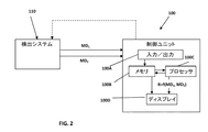
図2にブロック図で示すように、制御ユニット100は、典型例では、とりわけ、データ入力/出力ユーティリティー100A、メモリ100B、プロセッサ100C、および可能であればディスプレイ100Dなどのメインユーティリティーを有するコンピュータシステムである。血流検出システムからの、第1および第2の測定データ片MD1およびMD2を含む測定データが、受信され、分析されて、データ分析の結果と、可能であれば測定データ自体も、ディスプレイ100Dのグラフィック・ユーザインターフェイスに表示することができる。
As shown in a block diagram in FIG. 2, the
図1に戻ると、この実施例では、検出システム110が、(脳領域R1を構成する)人間の頭部に適用されて、脳の血流を表すデータ(第1の測定データ)の収集および測定を可能にする1以上の血流センサ112Aおよび/または112Bと;(脳領域R1以外の組織領域R2を構成する)身体の他の領域/組織に適用されて、この領域の血流(第2の測定データ)を測定する1以上のその他のプローブ/センサ・ユニット120および/または130とを具える。例えば、センサ120は上腕に、センサ130は下肢に適用される。2以上のセンサを頭部(脳領域)または身体の他の領域に適用することができ;または下記にさらに例示するように、すべての流れの測定に単一のセンサユニットを使用してもよいことを理解すべきである。
Returning to FIG. 1, in this embodiment, the
脳領域以外の領域R2の組織は、測定した患者の血流と血圧(平均の収縮または拡張)の間に線形の関数を示すような、または血圧変化と測定した血流の変化の間に線形の関数を示すような組織を選択することが好ましい。これが血圧指標を提供する。 Tissue regions R 2 other than the brain region, between the linear as shown functions, or changes in blood flow was measured with a blood pressure change between the blood flow and blood pressure of the patient measured (average of contraction or expansion) It is preferable to select a tissue that exhibits a linear function. This provides a blood pressure index.
一般に、検出システム110は、連続して血流を測定可能な、侵襲的または非侵襲的な既知の適切な種類の血流センサを使用することができる。本発明のシステムに使用可能な非侵襲的センサは、例えばUS8,143,605およびUS8,336,391に記載された例のように、光の超音波タグ付けの原理に基づくことが可能である。これらは両方とも譲受人である本出願人に譲渡され、この内容は特定の実施例に関して、参照により本明細書に組み込まれる。より具体的には、このような検出システムは、関心領域に1以上の音響タグ付けビームを照射する音響ユニットと、関心領域の少なくとも一部に所定の範囲の周波数の1以上の電磁放射のビームを照射するとともに、関心領域の電磁放射反応を検出する光学ユニットとを含む。この放射反応は、少なくとも血流パラメータを表す音響放射によりタグ付けされた電磁放射を含む。いくつかの実施例では、レーザドップラー原理に基づく検出システムを使用することができる。
In general, the
図2に示すように、制御ユニット100は、検出システムから(例えば各センサから)第1および第2の測定データMD1およびMD2を受信して、脳からの信号を収集するフローセンサ(112A、112B、またはこの両方)で測定したデータMD1と、その他の脳以外の領域からの信号を収集するフローセンサ(120、130、またはこの両方)で測定したデータMD2との間の関数関係、R=f(MD1,MD2)を計算する。例えば、このような関数関係は、移動相関係数、位相遅延、または相互相関の形態であるが、これらの関数だけに制限されない。計算結果は、関数として、または独立した指標として表示することができる。
As shown in FIG. 2, the
図3を参照すると、検出システム110が、脳以外と脳の両方の脈管構造を測定するのに用いる単一の血流センサ114を具えている、本発明の実施例が示されている。センサ114は、脳外の組織202と脳組織201の領域の測定に独立して適用されるよう構成され実施可能であり、こうして測定された第1および第2のデータは独立して分析される。制御ユニット(ここに図示せず)は、検出システム110から第1および第2の測定データを受信し、脳(領域201)で測定したデータと、その他の脳以外の領域(領域202)で測定したデータとの間の関数関係を計算する。例えば、このような関数関係は、移動相関係数、位相遅延、相互相関の形態であるが、これらの関数だけに制限されない。計算結果は、関数として、または独立した指標として表示することができる。検出システム110は、一方が脳外の組織を、もう一方が脳組織の脈管構造を測定するような、脳に設置された2つの個別の検出ユニットを具えてもよいことに留意されたい。
Referring to FIG. 3, an embodiment of the present invention is shown in which the
例として、図4は複合式の検出システム110をより詳細に示す。ここで、検出システムは、一の検出システムに組み合わせた2つのレーザドップラー・プローブ/センサのユニット210と212を具える。プローブ210は、脳組織に挿入されて脳の血流変化を測定し、プローブ212は皮膚の血流変化を測定するように構成されている。プローブ210と212は、それぞれ独立した測定データMD1とMD2を提供する。
As an example, FIG. 4 shows the combined
図5は、検出システム110の異なる構成を示し、これは上記の光の超音波タグ付けを利用した非侵襲的測定に基づく。この実施例では、検出システム110は、照明アセンブリ140と、少なくとも1つの感知アセンブリ142および可能な追加の感知アセンブリ(例えば142’)と、音響モジュール144とを具える。照明アセンブリと感知アセンブリと音響モジュールとの構成と動作は、譲受人である本出願人に譲渡された上記US8,143,605の記載のように実施してもよく、音響ポートに対する1以上の光出力ポートと光入力ポートの適切な配置が選択される。超音波305が、音響モジュールの出力ポートから放射される。光子302が、照明アセンブリ140から放出され、脳外組織202を通って伝搬し、ここで光子の少なくとも一部は超音波305と相互作用して、音響放射の周波数によりタグ付けされ、タグ付けされた光子とタグ付けされていない光子が感知アセンブリ142に到達する。感知アセンブリの出力を示すデータは、制御ユーティリティーで受信され、この制御ユーティリティーは、感知したタグ付けされた光子を分析して、領域202の血流についての情報を生成し、MD2を提供するように予めプログラムされている。同様に、光子303が脳組織201に照射され、ここで(少なくとも一部の)光子は超音波305と相互作用して、光子は照射された領域から戻って感知アセンブリ142’に到達する。制御ユーティリティーは、タグ付けされた光子303を示すデータを分析して、脳の領域201の血流についての情報を提供し、MD1を提供する。
FIG. 5 shows a different configuration of the
単一の感知アセンブリは、脳外の組織と脳の組織の両方を通って伝搬する光子を感知可能であり、感知したタグ付けされた信号の分析は、2つの組織領域に属するものに分けることができることに留意すべきである。これは、上記US8,143,605に記載されているように、感知した光信号と生成された超音波信号との相互相関を計算し、超音波信号の生成から異なる遅延時間でこの信号の振幅を分析することで達成される。 A single sensing assembly can sense photons propagating through both extra-cerebral and brain tissue, and analysis of the sensed tagged signal can be divided into those belonging to two tissue regions It should be noted that This calculates the cross-correlation between the sensed optical signal and the generated ultrasound signal as described in US 8,143,605 above, and the amplitude of this signal at different delay times from the generation of the ultrasound signal. This is achieved by analyzing
特に図示していないが、本発明での使用に適した検出システム110は、異なる種類の血流検出技術を用いてもよく、例えば検出技術に基づいて、レーザドップラープローブと光の超音波タグ付けとを組み合わせてもよいことに留意されたい。
Although not specifically shown,
図6は、本発明のモニタリングシステムによる測定の表示例を示す。データMD1およびMD2は、時間の関数として表示されている。グラフG1(ダイヤ形)は、一のセンサで収集されたデータMD1を表し、グラフG2(正方形)はデータMD2を表し、グラフG3(三角形)は(MD1とMD2との間の関係Rの関数fを構成する)移動相関係数を表す。 FIG. 6 shows a display example of measurement by the monitoring system of the present invention. Data MD 1 and MD 2 are displayed as a function of time. Graph G 1 (diamond shape) represents data MD 1 collected by one sensor, graph G 2 (square) represents data MD 2 , and graph G 3 (triangle) represents (of MD 1 and MD 2 Represents the mobile correlation coefficient (which constitutes the function f of the relationship R between).
この例では、移動相関係数は:各測定データMD1およびMD2を10秒間隔で平均化し;300秒ごとにMD1とMD2の間の相関係数(r)を計算して、例えば三角形などでディスプレイ上に表示し;相関係数が、各計算の間に10秒のステップを有する移動相関として計算する、ことにより計算される。図6において、16:04と(破線Lで示した)16:24との間では相関係数が1に近く、したがって自己調節が損なわれていることを表しており、一方で16:24以降の測定時間では相関係数が1より低く、この測定時間においては自己調節が損なわれていないことを表している。この資料のデータは、自己調節が損なわれている状態と損なわれていない状態との間の移行を示す閾値で変化しており、連続して表示することで、手術時に、自己調節機能の変化に関する連続的な情報を提供することができる。
In this example, the moving correlation coefficient is: average each measured data MD 1 and MD 2 at 10 second intervals; calculate the correlation coefficient (r) between MD 1 and MD 2 every 300 seconds, eg The correlation coefficient is calculated by calculating as a moving correlation with a 10 second step between each calculation. In FIG. 6, between 16:04 and 16:24 (shown by dashed line L), the correlation coefficient is close to 1, thus indicating that self-regulation is impaired, while 16:24 and later In this measurement time, the correlation coefficient is lower than 1, indicating that self-regulation is not impaired at this measurement time. The data in this document changes with a threshold that indicates the transition between the state where the self-regulation is impaired and the state where the self-regulation is not impaired. Continuous information about can be provided.
Claims (14)
患者の身体の関心領域である第1の領域および当該関心領域以外の組織領域である第2の領域での血流を測定し、前記第1の領域および前記第2の領域における血流を表す測定データを生成するように構成され動作可能な単一の血流センサを具える血流の検出システムと;
前記検出システムと通信し、前記関心領域と当該関心領域以外の組織領域での測定をほぼ同時に実行し、前記測定データを記録し、前記測定データを分析および処理して、前記第1の領域における血流に対応する第1の測定データと前記第2の領域における血流に対応する第2の測定データとを生成し、前記第1の測定データと前記第2の測定データとの間の関数の関係であって、前記関心領域の血流状況を表している関数の関係を特定し、前記関数の関係を示す出力データを生成するように構成され動作可能な制御ユニットと、
を具えることを特徴とするシステム。 A system for monitoring blood flow in a region of interest, the system:
Measuring blood flow in a first region that is a region of interest of the patient's body and a second region that is a tissue region other than the region of interest , and representing the blood flow in the first region and the second region a detection system for blood comprising a single blood flow sensor operable configured to generate to measurement data;
Communication with the detection system, said substantially performed simultaneously measured in the region of interest and tissue regions other than the region of interest, before Kihaka records constant data, the measurement data analysis and processing to the said first Generating first measurement data corresponding to blood flow in the region and second measurement data corresponding to blood flow in the second region; and between the first measurement data and the second measurement data a of relationship function to identify the relationship between function representing the blood flow status of the region of interest, and configured operable control unit to generate an output data showing the relationship between pre-Symbol function,
A system characterized by comprising.
患者の身体の関心領域である第1の領域および当該関心領域以外の組織領域である第2の領域でほぼ同時に行われた血流測定に対応する測定データを受信するデータ入力ユーティリティーと;
前記測定データを処理し、前記第1の領域での血流に対応する第1の測定データと前記第2の領域での血流に対応する第2の測定データとを生成し、前記第1の測定データと前記第2の測定データとの間の関数の関係であって、前記関心領域の血流状況を表している関数の関係を特定し、前記関数の関係を示す出力データを生成するように構成されたプロセッサユーティリティーとを具えることを特徴とする制御ユニット。 A control unit for use in a blood flow measurement system for monitoring blood flow conditions in a region of interest , the control unit comprising:
A data input utility for receiving the constant data measurement that corresponds to the near-simultaneous blood flow measured in the second region is a first region and the interest set other than the areas woven region is a region of interest of the patient's body ;
Before Kihaka processes constant data, to generate a second measurement data corresponding to the blood flow in the first measurement data and the second region corresponding to the blood flow in the first region, the a relationship function between the first measurement data second measurement data to identify the relationship between function representing the blood flow status of the region of interest, showing the relationship between pre-Symbol function output A control unit comprising a processor utility configured to generate data.
患者の身体の関心領域である第1の領域および当該関心領域以外の組織領域である第2の領域でほぼ同時に行われた血流測定に対応する測定データを提供するステップと;
前記測定データを処理して、前記第1の領域および前記第2の領域における血流にそれぞれ対応する第1の測定データと第2の測定データを生成し、前記第1の測定データと前記第2の測定データとの間の関数の関係を特定し、前記関数の関係を示す出力データを生成するステップであって、前記関数の関係が、前記関心領域での血流状況を表している、ステップと、
を具えることを特徴とする方法。 A method for monitoring blood flow in a region of interest , the method comprising:
Providing a constant data measurement that corresponds to the near-simultaneous blood flow measured in the first and second regions is the organization region other than the region of interest is a region of interest of a patient's body;
Processing the pre Kihaka constant data, first generating the measurement data and the second measurement data respectively corresponding to the blood flow in the first region and the second region, said first measurement data identifying a relationship function between the second measurement data, and generating an output data showing the relationship between pre-Symbol function, the relationship of the function, representing the blood flow conditions in the region of interest Step , and
A method characterized by comprising.
患者の身体の関心領域である第1の領域での血流を測定し、前記第1の領域における血流に対応する第1の測定データを生成するとともに、前記関心領域以外の組織領域である第2の領域での血流を測定し、前記第2の領域における血流に対応する第2の測定データを生成するように構成され動作可能な単一の血流センサを具える血流の検出システムと;
前記検出システムと通信し、前記第1および第2の領域での測定をほぼ同時に実行し、前記第1および第2の測定データを記録するように構成された制御ユニットと;を具え、
前記単一の血流センサが、前記非侵襲かつ直接的な血流の測定用に構成されており、当該血流センサが、前記第1および第2の領域の少なくとも一部に超音波を放射するように構成され動作可能な音響モジュールと、前記超音波が放射された第1および第2の領域を光で照射するように構成され動作可能な照明モジュールと、前記第1および第2の領域の各々から超音波タグ付けされた光を受ける感知モジュールと、を有しており、
前記制御ユニットが、前記第1および第2の測定データの各々を分析すること、前記第1の測定データと前記第2の測定データとの間の関数の関係であって、前記関心領域における血流状況を表す関数の関係を特定すること、および前記関数の関係を示す出力データを生成すること、を独立して行うように構成され動作可能であることを特徴とするシステム。 A system used for monitoring a single blood flow situation in a region of interest, the system comprising:
A blood flow is measured in a first region that is a region of interest of the patient's body, and first measurement data corresponding to the blood flow in the first region is generated, and a tissue region other than the region of interest A blood flow comprising a single blood flow sensor configured and operable to measure blood flow in a second region and generate second measurement data corresponding to the blood flow in the second region. A detection system;
A control unit configured to communicate with the detection system, perform measurements in the first and second regions substantially simultaneously, and record the first and second measurement data;
The single blood flow sensor is configured for non-invasive and direct blood flow measurement, and the blood flow sensor emits ultrasonic waves to at least a part of the first and second regions. An acoustic module configured and operable, an illumination module configured and operable to illuminate the first and second regions from which the ultrasonic waves are emitted, and the first and second regions and sensitive knowledge module from each of Ru receiving ultrasound tagged light, it has a,
Wherein the control unit is determined by analyzing each of the first and second measurement data, a relationship function between the first measurement data and the second measurement data, in the region of interest A system configured and operable to independently identify a relationship between functions representing a blood flow situation and to generate output data indicating the relationship between the functions .
Applications Claiming Priority (3)
| Application Number | Priority Date | Filing Date | Title |
|---|---|---|---|
| US201261738768P | 2012-12-18 | 2012-12-18 | |
| US61/738,768 | 2012-12-18 | ||
| PCT/IL2013/051029 WO2014097293A1 (en) | 2012-12-18 | 2013-12-18 | System and method for monitoring blood flow condition in region of interest in patient's body |
Publications (3)
| Publication Number | Publication Date |
|---|---|
| JP2016504088A JP2016504088A (en) | 2016-02-12 |
| JP2016504088A5 JP2016504088A5 (en) | 2017-02-02 |
| JP6345689B2 true JP6345689B2 (en) | 2018-06-20 |
Family
ID=50977723
Family Applications (1)
| Application Number | Title | Priority Date | Filing Date |
|---|---|---|---|
| JP2015547273A Expired - Fee Related JP6345689B2 (en) | 2012-12-18 | 2013-12-18 | System and method for monitoring blood flow in a region of interest within a patient's body |
Country Status (6)
| Country | Link |
|---|---|
| US (1) | US20150327779A1 (en) |
| EP (1) | EP2934306A4 (en) |
| JP (1) | JP6345689B2 (en) |
| CN (1) | CN104869896B (en) |
| HK (1) | HK1212189A1 (en) |
| WO (1) | WO2014097293A1 (en) |
Families Citing this family (7)
| Publication number | Priority date | Publication date | Assignee | Title |
|---|---|---|---|---|
| US10499818B2 (en) * | 2015-10-19 | 2019-12-10 | Covidien Lp | System and method for providing blood pressure safe zone indication during autoregulation monitoring |
| JP6922301B2 (en) * | 2017-03-22 | 2021-08-18 | カシオ計算機株式会社 | Electronic devices, graph drawing systems, graph drawing methods, and programs |
| JP6973296B2 (en) * | 2018-05-28 | 2021-11-24 | 日本電信電話株式会社 | In-vivo temperature measuring device and in-vivo temperature measuring method |
| US10932673B2 (en) * | 2018-10-19 | 2021-03-02 | Covidien Lp | Non-cerebral organ autoregulation status determination |
| US11478200B2 (en) * | 2018-12-12 | 2022-10-25 | Covidien Lp | Blood pressure and autoregulation monitoring |
| US11890132B2 (en) * | 2020-02-28 | 2024-02-06 | Fujifilm Sonosite, Inc. | Detecting fluid flows using ultrasound imaging systems |
| US11839471B2 (en) | 2021-03-23 | 2023-12-12 | Covidien Lp | Autoregulation monitoring using deep learning |
Family Cites Families (18)
| Publication number | Priority date | Publication date | Assignee | Title |
|---|---|---|---|---|
| US6743196B2 (en) * | 1999-03-01 | 2004-06-01 | Coaxia, Inc. | Partial aortic occlusion devices and methods for cerebral perfusion augmentation |
| US6887199B2 (en) * | 1999-09-23 | 2005-05-03 | Active Signal Technologies, Inc. | Brain assessment monitor |
| US20060100530A1 (en) * | 2000-11-28 | 2006-05-11 | Allez Physionix Limited | Systems and methods for non-invasive detection and monitoring of cardiac and blood parameters |
| WO2002043564A2 (en) * | 2000-11-28 | 2002-06-06 | Allez Physionix Limited | Systems and methods for making non-invasive physiological assessments |
| WO2006011128A1 (en) * | 2004-07-15 | 2006-02-02 | Orsan Medical Technologies Ltd. | Cerebral perfusion monitor |
| EP2392262A1 (en) * | 2003-06-03 | 2011-12-07 | PhysioSonics, Inc. | Methods and systems for locating and acoustically illuminating a desired target area |
| JP3876322B2 (en) * | 2003-12-03 | 2007-01-31 | 独立行政法人情報通信研究機構 | Non-invasive brain activity measurement method |
| US20060122513A1 (en) * | 2004-12-06 | 2006-06-08 | Taylor William G | Doppler helmet |
| PL1863387T3 (en) * | 2005-03-16 | 2013-11-29 | Or Nim Medical Ltd | Noninvasive measurements in a human body |
| US20070093702A1 (en) * | 2005-10-26 | 2007-04-26 | Skyline Biomedical, Inc. | Apparatus and method for non-invasive and minimally-invasive sensing of parameters relating to blood |
| EP2117422B1 (en) * | 2007-02-02 | 2015-12-09 | The Johns Hopkins University | A method and system for determining a cerebrovascular autoregulation state of a patient |
| US7541602B2 (en) * | 2007-06-04 | 2009-06-02 | Or-Nim Medical Ltd. | System and method for noninvasively monitoring conditions of a subject |
| KR20100133996A (en) * | 2008-03-11 | 2010-12-22 | 카롤린스카 인스티튜테트 이노베이션스 아베 | A computer-based method and system for imaging-based dynamic function evaluation of an organ |
| WO2009126885A1 (en) * | 2008-04-11 | 2009-10-15 | Somanetics Corporation | System and method for differentiating between tissue-specific and systemic causes of changes in oxygen saturation in tissue and organs |
| US8336391B2 (en) * | 2008-07-06 | 2012-12-25 | Or-Nim Medical Ltd. | Method and system for non-invasively monitoring fluid flow in a subject |
| WO2010072416A1 (en) * | 2008-12-23 | 2010-07-01 | Charite-Universitätsmedizin Berlin | Method and device for monitoring and improving arteriogenesis |
| RU2012108849A (en) * | 2009-08-10 | 2013-09-20 | П2-Сайенс Апс | UTP FOR DIAGNOSTIC OF STENOSIS AND OTHER CONDITIONS OF LIMITED BLEED |
| US9474451B2 (en) * | 2011-04-01 | 2016-10-25 | Raba Equity Partners Ii, Llc | Systems and methods for varying blood flow to identify autoregulatory ranges in a patient |
-
2013
- 2013-12-18 WO PCT/IL2013/051029 patent/WO2014097293A1/en active Application Filing
- 2013-12-18 CN CN201380066726.9A patent/CN104869896B/en not_active Expired - Fee Related
- 2013-12-18 JP JP2015547273A patent/JP6345689B2/en not_active Expired - Fee Related
- 2013-12-18 US US14/652,965 patent/US20150327779A1/en not_active Abandoned
- 2013-12-18 EP EP13864623.7A patent/EP2934306A4/en not_active Withdrawn
-
2016
- 2016-01-12 HK HK16100284.7A patent/HK1212189A1/en not_active IP Right Cessation
Also Published As
| Publication number | Publication date |
|---|---|
| US20150327779A1 (en) | 2015-11-19 |
| EP2934306A4 (en) | 2016-05-25 |
| WO2014097293A1 (en) | 2014-06-26 |
| JP2016504088A (en) | 2016-02-12 |
| CN104869896B (en) | 2017-05-31 |
| CN104869896A (en) | 2015-08-26 |
| HK1212189A1 (en) | 2016-06-10 |
| EP2934306A1 (en) | 2015-10-28 |
Similar Documents
| Publication | Publication Date | Title |
|---|---|---|
| JP6345689B2 (en) | System and method for monitoring blood flow in a region of interest within a patient's body | |
| JP6837990B2 (en) | Systems and methods for monitoring absolute blood flow | |
| JP7458078B2 (en) | Tissue measurement sensor | |
| US8126524B2 (en) | Method and apparatus for noninvasively monitoring parameters of a region of interest in a human body | |
| TWI672126B (en) | Carotid blood pressure detection device | |
| EP1219241B1 (en) | Stethoscope | |
| US10835202B2 (en) | System and method for analyzing tissue using shear waves | |
| US20080312533A1 (en) | Noninvasive Measurements in a Human Body | |
| US20150126865A1 (en) | Ultrasonic probe and ultrasonic measuring device | |
| US11116409B2 (en) | Devices and methods for detection of internal bleeding and hematoma | |
| JP2009512500A (en) | Ultra-high specificity device and method for screening of internal tumors | |
| US20120203093A1 (en) | Apparatus, system and methods for photoacoustic detection of deep vein thrombosis | |
| JP7279010B2 (en) | portable ultrasound device | |
| JP4412644B2 (en) | Cardiodynamic measurement device | |
| Jeger-Madiot et al. | Non-contact and through-clothing measurement of the heart rate using ultrasound vibrocardiography | |
| JP2016504088A5 (en) | ||
| US10265544B2 (en) | Real-time tumor perfusion imaging during radiation therapy delivery | |
| JP2004073559A (en) | Diagnostic imaging apparatus | |
| JP4739878B2 (en) | Cerebral blood flow measuring device | |
| EP2339957A1 (en) | Method and system for non-invasively monitoring fluid flow in a subject | |
| US20180177442A1 (en) | Processing apparatus and processing method | |
| AbuRahma | Overview of noninvasive vascular techniques in peripheral arterial disease | |
| IL239240A (en) | Methods and systems for monitoring intrabody tissues |
Legal Events
| Date | Code | Title | Description |
|---|---|---|---|
| A521 | Written amendment |
Free format text: JAPANESE INTERMEDIATE CODE: A523 Effective date: 20161215 |
|
| A621 | Written request for application examination |
Free format text: JAPANESE INTERMEDIATE CODE: A621 Effective date: 20161215 |
|
| A977 | Report on retrieval |
Free format text: JAPANESE INTERMEDIATE CODE: A971007 Effective date: 20170913 |
|
| A131 | Notification of reasons for refusal |
Free format text: JAPANESE INTERMEDIATE CODE: A131 Effective date: 20170919 |
|
| A601 | Written request for extension of time |
Free format text: JAPANESE INTERMEDIATE CODE: A601 Effective date: 20171214 |
|
| A521 | Written amendment |
Free format text: JAPANESE INTERMEDIATE CODE: A523 Effective date: 20180216 |
|
| TRDD | Decision of grant or rejection written | ||
| A01 | Written decision to grant a patent or to grant a registration (utility model) |
Free format text: JAPANESE INTERMEDIATE CODE: A01 Effective date: 20180424 |
|
| A61 | First payment of annual fees (during grant procedure) |
Free format text: JAPANESE INTERMEDIATE CODE: A61 Effective date: 20180523 |
|
| R150 | Certificate of patent or registration of utility model |
Ref document number: 6345689 Country of ref document: JP Free format text: JAPANESE INTERMEDIATE CODE: R150 |
|
| LAPS | Cancellation because of no payment of annual fees |