JP6344608B2 - Image processing apparatus, image processing method, program, and surgical system - Google Patents
Image processing apparatus, image processing method, program, and surgical system Download PDFInfo
- Publication number
- JP6344608B2 JP6344608B2 JP2015021078A JP2015021078A JP6344608B2 JP 6344608 B2 JP6344608 B2 JP 6344608B2 JP 2015021078 A JP2015021078 A JP 2015021078A JP 2015021078 A JP2015021078 A JP 2015021078A JP 6344608 B2 JP6344608 B2 JP 6344608B2
- Authority
- JP
- Japan
- Prior art keywords
- image
- pixel
- surgical
- target position
- illumination
- Prior art date
- Legal status (The legal status is an assumption and is not a legal conclusion. Google has not performed a legal analysis and makes no representation as to the accuracy of the status listed.)
- Active
Links
Images


Classifications
-
- A—HUMAN NECESSITIES
- A61—MEDICAL OR VETERINARY SCIENCE; HYGIENE
- A61B—DIAGNOSIS; SURGERY; IDENTIFICATION
- A61B1/00—Instruments for performing medical examinations of the interior of cavities or tubes of the body by visual or photographical inspection, e.g. endoscopes; Illuminating arrangements therefor
- A61B1/00002—Operational features of endoscopes
- A61B1/00004—Operational features of endoscopes characterised by electronic signal processing
- A61B1/00009—Operational features of endoscopes characterised by electronic signal processing of image signals during a use of endoscope
-
- A—HUMAN NECESSITIES
- A61—MEDICAL OR VETERINARY SCIENCE; HYGIENE
- A61B—DIAGNOSIS; SURGERY; IDENTIFICATION
- A61B1/00—Instruments for performing medical examinations of the interior of cavities or tubes of the body by visual or photographical inspection, e.g. endoscopes; Illuminating arrangements therefor
- A61B1/06—Instruments for performing medical examinations of the interior of cavities or tubes of the body by visual or photographical inspection, e.g. endoscopes; Illuminating arrangements therefor with illuminating arrangements
- A61B1/0623—Instruments for performing medical examinations of the interior of cavities or tubes of the body by visual or photographical inspection, e.g. endoscopes; Illuminating arrangements therefor with illuminating arrangements for off-axis illumination
-
- A—HUMAN NECESSITIES
- A61—MEDICAL OR VETERINARY SCIENCE; HYGIENE
- A61B—DIAGNOSIS; SURGERY; IDENTIFICATION
- A61B1/00—Instruments for performing medical examinations of the interior of cavities or tubes of the body by visual or photographical inspection, e.g. endoscopes; Illuminating arrangements therefor
- A61B1/06—Instruments for performing medical examinations of the interior of cavities or tubes of the body by visual or photographical inspection, e.g. endoscopes; Illuminating arrangements therefor with illuminating arrangements
- A61B1/0661—Endoscope light sources
- A61B1/0669—Endoscope light sources at proximal end of an endoscope
-
- A—HUMAN NECESSITIES
- A61—MEDICAL OR VETERINARY SCIENCE; HYGIENE
- A61B—DIAGNOSIS; SURGERY; IDENTIFICATION
- A61B1/00—Instruments for performing medical examinations of the interior of cavities or tubes of the body by visual or photographical inspection, e.g. endoscopes; Illuminating arrangements therefor
- A61B1/06—Instruments for performing medical examinations of the interior of cavities or tubes of the body by visual or photographical inspection, e.g. endoscopes; Illuminating arrangements therefor with illuminating arrangements
- A61B1/0661—Endoscope light sources
- A61B1/0676—Endoscope light sources at distal tip of an endoscope
-
- A—HUMAN NECESSITIES
- A61—MEDICAL OR VETERINARY SCIENCE; HYGIENE
- A61B—DIAGNOSIS; SURGERY; IDENTIFICATION
- A61B1/00—Instruments for performing medical examinations of the interior of cavities or tubes of the body by visual or photographical inspection, e.g. endoscopes; Illuminating arrangements therefor
- A61B1/06—Instruments for performing medical examinations of the interior of cavities or tubes of the body by visual or photographical inspection, e.g. endoscopes; Illuminating arrangements therefor with illuminating arrangements
- A61B1/0661—Endoscope light sources
- A61B1/0684—Endoscope light sources using light emitting diodes [LED]
-
- H—ELECTRICITY
- H04—ELECTRIC COMMUNICATION TECHNIQUE
- H04N—PICTORIAL COMMUNICATION, e.g. TELEVISION
- H04N23/00—Cameras or camera modules comprising electronic image sensors; Control thereof
- H04N23/56—Cameras or camera modules comprising electronic image sensors; Control thereof provided with illuminating means
Landscapes
- Health & Medical Sciences (AREA)
- Life Sciences & Earth Sciences (AREA)
- Surgery (AREA)
- Engineering & Computer Science (AREA)
- Optics & Photonics (AREA)
- Physics & Mathematics (AREA)
- Biophysics (AREA)
- General Health & Medical Sciences (AREA)
- Pathology (AREA)
- Radiology & Medical Imaging (AREA)
- Veterinary Medicine (AREA)
- Biomedical Technology (AREA)
- Heart & Thoracic Surgery (AREA)
- Medical Informatics (AREA)
- Molecular Biology (AREA)
- Animal Behavior & Ethology (AREA)
- Nuclear Medicine, Radiotherapy & Molecular Imaging (AREA)
- Public Health (AREA)
- Signal Processing (AREA)
- Microelectronics & Electronic Packaging (AREA)
- Endoscopes (AREA)
- Instruments For Viewing The Inside Of Hollow Bodies (AREA)
Description
本技術は、画像処理装置、画像処理方法、プログラム、及び、手術システムに関し、特に、例えば、鏡面反射光成分を抑制することができるようにする画像処理装置、画像処理方法、プログラム、及び、手術システムに関する。 The present technology relates to an image processing device, an image processing method, a program, and a surgical system, and particularly, for example, an image processing device, an image processing method, a program, and a surgery that can suppress a specular reflection light component. About the system.
例えば、手術や診断において、内視鏡で被写体を観察する場合には、鏡面反射(正反射)が生じやすい。鏡面反射による鏡面反射光は、被写体の観察の妨げとなるため、鏡面反射については、何らかの対処を施すことが要請されている。 For example, when observing a subject with an endoscope in surgery or diagnosis, specular reflection (regular reflection) tends to occur. Specular reflection light caused by specular reflection hinders observation of a subject, and therefore some countermeasure is required for specular reflection.
鏡面反射に対処する技術としては、例えば、画像処理によって、二色性反射モデルに基づき、内視鏡で撮影された内視鏡画像に含まれる、鏡面反射光に対応する鏡面反射光成分を推定して除去する技術や、内視鏡画像の輝度を調整する技術が提案されている(例えば、特許文献1や2を参照)。
As a technique for dealing with specular reflection, for example, the specular reflection component corresponding to the specular reflection light included in the endoscopic image captured by the endoscope is estimated based on the dichroic reflection model by image processing. A technique for removing the image and a technique for adjusting the luminance of the endoscopic image have been proposed (see, for example,
内視鏡画像の鏡面反射光成分は、被写体である臓器等の凹凸や模様等の観察の妨げになるため、内視鏡画像の鏡面反射光成分を抑制する様々な技術の提案が要請されている。 The specular reflection component of the endoscopic image hinders observation of unevenness and patterns of the organ that is the subject, and therefore proposals for various techniques for suppressing the specular reflection component of the endoscopic image are required. Yes.
本技術は、このような状況に鑑みてなされたものであり、鏡面反射光成分を抑制することができるようにするものである。 The present technology has been made in view of such a situation, and makes it possible to suppress a specular reflection light component.
本技術の画像処理装置、又は、プログラムは、第1の照明方向の照明が照射された術部を撮影した第1の手術画像と、第2の照明方向の照明光が照射された前記術部を撮影した第2の手術画像とを合成し、鏡面反射光成分が抑制された合成画像を生成する信号処理部を備え、前記第1の手術画像は、奇数フレーム及び偶数フレームのうちの一方のフレームの画像であり、前記第2の手術画像は、前記奇数フレーム及び前記偶数フレームのうちの他方のフレームの画像であり、前記信号処理部は、前記第1の手術画像又は前記第2の手術画像のいずれかの注目画素の露光量及び画素値に基づいて、前記合成画像中の前記注目画素に対応する画素の画素値を決定する画像処理装置、又は、そのような画像処理装置として、コンピュータを機能させるためのプログラムである。 The image processing apparatus or the program according to the present technology may include a first surgical image obtained by photographing a surgical unit irradiated with illumination in the first illumination direction and the surgical unit irradiated with illumination light in the second illumination direction. And a signal processing unit that generates a composite image in which the specular reflection light component is suppressed, and the first surgical image includes one of an odd frame and an even frame. an image of the frame, the second surgical image, the odd-numbered frame and Ri other image der frame of the even frame, the signal processing unit, the first operation image or the second As an image processing device for determining a pixel value of a pixel corresponding to the target pixel in the composite image based on an exposure amount and a pixel value of any target pixel of the surgical image , or such an image processing device, Make the computer work It is a program for.
本技術の画像処理方法は、画像処理装置の画像処理方法であって、前記画像処理装置が、第1の照明方向の照明光が照射された術部を撮影した第1の手術画像と、第2の照明方向の照明光が照射された前記術部を撮影した第2の手術画像とを合成し、鏡面反射光成分が抑制された合成画像を生成するステップを含み、前記第1の手術画像は、奇数フレーム及び偶数フレームのうちの一方のフレームの画像であり、前記第2の手術画像は、前記奇数フレーム及び前記偶数フレームのうちの他方のフレームの画像であり、前記第1の手術画像又は前記第2の手術画像のいずれかの注目画素の露光量及び画素値に基づいて、前記合成画像中の前記注目画素に対応する画素の画素値を決定するステップを含む画像処理方法である。 An image processing method according to an embodiment of the present technology is an image processing method of an image processing device, wherein the image processing device captures a first surgical image obtained by photographing a surgical site irradiated with illumination light in a first illumination direction, A first surgical image including a step of generating a composite image in which a specular reflection light component is suppressed by combining the second surgical image obtained by photographing the surgical part irradiated with illumination light in the illumination direction of 2; is an image of one frame among the odd and even frames, the second surgical image, the Ri odd frame and the image der of the other frame of the even frame, the first surgical An image processing method including a step of determining a pixel value of a pixel corresponding to the target pixel in the composite image based on an exposure amount and a pixel value of the target pixel of either the image or the second surgical image. .
本技術の手術システムは、術部を撮影する手術用撮像装置と、第1の照明方向の照明光が照射された術部を前記手術用撮像装置で撮影した第1の手術画像と、第2の照明方向の照明光が照射された前記術部を前記手術用撮像装置で撮影した第2の手術画像とを合成し、鏡面反射光成分が抑制された合成画像を生成する信号処理部とを備え、前記第1の手術画像は、奇数フレーム及び偶数フレームのうちの一方のフレームの画像であり、前記第2の手術画像は、前記奇数フレーム及び前記偶数フレームのうちの他方のフレームの画像であり、前記信号処理部は、前記第1の手術画像又は前記第2の手術画像のいずれかの注目画素の露光量及び画素値に基づいて、前記合成画像中の前記注目画素に対応する画素の画素値を決定する手術システムである。 The surgical operation system according to the present technology includes a surgical imaging apparatus that images a surgical part, a first surgical image obtained by capturing a surgical part irradiated with illumination light in a first illumination direction with the surgical imaging apparatus, and a second A signal processing unit that combines the second surgical image obtained by imaging the surgical unit irradiated with illumination light in the illumination direction with the surgical imaging apparatus and generates a composite image in which a specular reflection component is suppressed; The first surgical image is an image of one of an odd frame and an even frame, and the second surgical image is an image of the other of the odd frame and the even frame. Ah is, the signal processing unit, the exposure amount of any of the target pixel of the first surgical image or said second surgical image and on the basis of the pixel value, the pixel corresponding to the pixel of interest in the composite image in surgical system to determine a pixel value That.
本技術においては、第1の照明方向の照明が照射された術部を撮影した第1の手術画像と、第2の照明方向の照明光が照射された前記術部を撮影した第2の手術画像とが合成され、鏡面反射光成分が抑制された合成画像が生成される。また、前記第1の手術画像が、奇数フレーム及び偶数フレームのうちの一方のフレームの画像とされ、前記第2の手術画像が、前記奇数フレーム及び前記偶数フレームのうちの他方のフレームの画像とされる。また、前記第1の手術画像又は前記第2の手術画像のいずれかの注目画素の露光量及び画素値に基づいて、前記合成画像中の前記注目画素に対応する画素の画素値が決定される。 In the present technology, a first operation image obtained by photographing the surgical part irradiated with illumination in the first illumination direction and a second operation obtained by photographing the surgical part irradiated with illumination light in the second illumination direction. The combined image is generated by combining the image and the specular reflection light component. Further, the first surgical image is an image of one of an odd frame and an even frame, and the second surgical image is an image of the other of the odd frame and the even frame. Is done. Further, the pixel value of the pixel corresponding to the target pixel in the composite image is determined based on the exposure amount and the pixel value of the target pixel of either the first surgical image or the second surgical image. .
なお、プログラムは、伝送媒体を介して伝送することにより、又は、記録媒体に記録して、提供することができる。 The program can be provided by being transmitted through a transmission medium or by being recorded on a recording medium.
また、画像処理装置は、独立した装置であっても良いし、1つの装置を構成している内部ブロックであっても良い。 In addition, the image processing apparatus may be an independent apparatus or may be an internal block constituting one apparatus.
本技術によれば、鏡面反射光成分を抑制することができる。 According to the present technology, a specular reflection light component can be suppressed.
なお、ここに記載された効果は必ずしも限定されるものではなく、本開示中に記載されたいずれかの効果であってもよい。 Note that the effects described here are not necessarily limited, and may be any of the effects described in the present disclosure.
<本技術を適用した内視鏡システムの一実施の形態> <One embodiment of an endoscope system to which the present technology is applied>
図1は、本技術を適用した内視鏡システムの一実施の形態の構成例を示すブロック図である。 FIG. 1 is a block diagram illustrating a configuration example of an embodiment of an endoscope system to which the present technology is applied.
図1において、内視鏡システムは、内視鏡11、メモリ12、信号処理部13、表示部14、撮影制御部15、照明制御部16、及び、照明部17を有する。
In FIG. 1, the endoscope system includes an
内視鏡11は、例えば、CCD(Charge Coupled Device)やCMOS(Complementary Metal Oxide Semiconductor)センサ等のイメージセンサ11Aを有し、そのイメージセンサ11Aによって被写体を撮影することにより得られる撮影画像を、メモリ12、及び、信号処理部13に供給する。
The
ここで、図1の内視鏡システムは、例えば、医療用の内視鏡システムであり、内視鏡11のイメージセンサ11Aでは、被写体としての生体、すなわち、例えば、患者の体腔の組織が撮影される。そして、その生体の撮影により得られる生体画像である内視鏡画像が、内視鏡11から、メモリ12、及び、信号処理部13に供給される。
Here, the endoscope system of FIG. 1 is, for example, a medical endoscope system, and the
なお、図示していないが、内視鏡11は、必要に応じて、例えば、フォーカスレンズや絞り等の光学系を有する。
Although not shown, the
さらに、内視鏡11では、内視鏡画像として、2D(Dimension)画像を撮影することもできるし、3D画像を撮影することもできる。
Furthermore, the
メモリ12は、内視鏡11(のイメージセンサ11A)から供給される内視鏡画像を一時記憶する。
The
信号処理部13は、内視鏡11(のイメージセンサ11A)から供給される内視鏡画像や、メモリ12に記憶された内視鏡画像を用いて、信号処理を行い、その信号処理の結果得られる画像を、表示部14に供給する。
The
ここで、信号処理部13で行われる信号処理としては、例えば、ベイヤ配列の画像の各画素についてRGBの値を求めるデモザイク(現像)や、後述する合成処理等がある。合成処理では、内視鏡11からの内視鏡画像と、メモリ12に記憶された内視鏡画像とが合成され、その結果得られる合成画像が、表示部14に供給される。
Here, the signal processing performed by the
表示部14は、信号処理部13から供給される合成画像を表示する。表示部14としては、例えば、信号処理部13と一体となったディスプレイや、信号処理部13とは別個の据え置き型のディスプレイ、ヘッドマウントディスプレイ等を採用することができる。
The
撮影制御部15は、内視鏡11(のイメージセンサ11A)での内視鏡画像の撮影を制御する。また、撮影制御部15は、内視鏡11で撮影された内視鏡画像を、メモリ12又は信号処理部13に供給する制御を行う。
The imaging control unit 15 controls imaging of an endoscopic image with the endoscope 11 (the
さらに、撮影制御部15は、内視鏡11で撮影される内視鏡画像のフレームに適した照明の条件(照明条件)を設定し、照明制御部16に供給する。
Further, the imaging control unit 15 sets an illumination condition (illumination condition) suitable for the frame of the endoscopic image captured by the
すなわち、内視鏡11では、所定のフレームレートで、内視鏡画像が撮影される。撮影制御部15は、内視鏡画像の各フレームについて、照明条件を設定し、照明制御部16に供給する。
That is, the
照明制御部16は、被写体が撮影制御部15からの照明条件に従って照明されるように、照明部17を制御する。
The
照明部17は、照明制御部16の制御に従って、照明光を照射することにより、被写体を照明する。
The illumination unit 17 illuminates the subject by irradiating illumination light according to the control of the
ここで、照明部17は、照明光となる光を発するハロゲンランプ、キセノンランプ、LED (Light Emitting Diode)等の光源、及び、その光源が発した照明光を、被写体に導くライトガイドケーブル等の光学部品等の、被写体に照明光を照射するためのすべての機構を含む。 Here, the illumination unit 17 includes a light source such as a halogen lamp, a xenon lamp, or an LED (Light Emitting Diode) that emits illumination light, and a light guide cable that guides the illumination light emitted from the light source to a subject. It includes all mechanisms for irradiating the subject with illumination light, such as optical components.
照明部17は、照明制御部16の制御に従い、例えば、偶数フレームと奇数フレームとで、異なる照明方向の照明光を、被写体に照射する。
The illumination unit 17 irradiates the subject with illumination light in different illumination directions in, for example, even frames and odd frames according to the control of the
すなわち、偶数フレームの内視鏡画像の撮影時には、照明部17は、例えば、内視鏡画像に映る被写体の中心部分に向かう照明方向(第1の照明方向)(以下、中心方向ともいう)の照明光を、被写体に照射する。 That is, at the time of capturing an even number of endoscopic images, the illumination unit 17 has, for example, an illumination direction (first illumination direction) (hereinafter also referred to as a center direction) toward the center portion of the subject shown in the endoscopic image. Illuminate the subject with illumination light.
また、奇数フレームの内視鏡画像の撮影時には、照明部17は、例えば、内視鏡画像に映る被写体の周辺部分に向かう照明方向(第2の照明方向)(以下、周辺方向ともいう)の照明光を、被写体に照射する。 Further, at the time of capturing an endoscopic image of an odd number of frames, the illuminating unit 17 has, for example, an illuminating direction (second illuminating direction) (hereinafter also referred to as a peripheral direction) toward the peripheral portion of the subject shown in the endoscopic image. Illuminate the subject with illumination light.
その結果、内視鏡11では、偶数フレームの内視鏡画像(第1の撮影画像)として、中心方向の照明光が照射された被写体を撮影した画像が得られるとともに、奇数フレームの内視鏡画像(第2の撮影画像)として、周辺方向の照明光が照射された被写体を撮影した画像が得られる。
As a result, the
信号処理部13で行われる合成処理では、以上のような偶数フレームの内視鏡画像と、奇数フレームの内視鏡画像とが合成される。
In the synthesizing process performed in the
なお、照明部17の一部、又は、全部は、内視鏡11に含めることができる。
Note that a part or all of the illumination unit 17 can be included in the
また、照明部17から被写体に照射する照明光の数は、特に限定されるものではない。すなわち、照明部17は、1又は複数の照明光を、被写体に照射することができる。 Moreover, the number of illumination lights irradiated to a to-be-photographed object from the illumination part 17 is not specifically limited. That is, the illumination unit 17 can irradiate the subject with one or a plurality of illumination lights.
さらに、中心方向の照明光は、偶数フレームではなく、奇数フレームの内視鏡画像の撮影時に照射し、周辺方向の照明光は、奇数フレームではなく、偶数フレームの内視鏡画像の撮影時に照射することができる。 Furthermore, the illumination light in the central direction is emitted when capturing an endoscopic image of an odd frame, not an even frame, and the illumination light in the peripheral direction is irradiated when capturing an endoscopic image of an even frame, not an odd frame. can do.
また、照明光の照明方向の数としては、中心方向と周辺方向との2方向の他、3方向以上を採用することができる。 As the number of illumination directions of illumination light, three or more directions can be adopted in addition to the two directions of the center direction and the peripheral direction.
すなわち、照明光の照明方向の数としては、例えば、被写体の左側に向かう方向、被写体の中央に向かう方向、及び、被写体の右側に向かう方向の3方向や、被写体の左上、左下、右上、及び、右下のそれぞれに向かう4方向等を採用することができる。 That is, as the number of illumination directions of illumination light, for example, three directions, a direction toward the left side of the subject, a direction toward the center of the subject, and a direction toward the right side of the subject, and the upper left, lower left, upper right, and , 4 directions toward each of the lower right can be adopted.
照明光の照明方向の数として、K方向を採用する場合、内視鏡システムでは、例えば、連続するKフレームの内視鏡画像として、照明方向がK方向のそれぞれになっているKフレームの画像が撮影され、その連続するKフレームの内視鏡画像が、1フレームの合成画像に合成される。 When adopting the K direction as the number of illumination directions of illumination light, in an endoscope system, for example, as an endoscopic image of continuous K frames, images of K frames in which the illumination directions are respectively in the K direction Are captured, and the continuous K-frame endoscopic images are combined into a single-frame composite image.
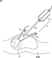
図2は、図1の内視鏡システムの使用例を示す図である。 FIG. 2 is a diagram illustrating a usage example of the endoscope system of FIG.
図1の内視鏡システムは、例えば、手術対象となる体内の部位である術部32を被写体として撮影して、その被写体が映った内視鏡画像(合成画像)を、表示部14に表示し、医師が、内視鏡画像を見ながら、術部32に処置を施す内視鏡下手術等で用いられる。
The endoscope system of FIG. 1 shoots, for example, a
内視鏡11は、例えば、患者(人体)の体腔に挿入され、その体腔内の組織を被写体とする内視鏡画像を撮影する。
The
すなわち、内視鏡11は、例えば、外観上、内視鏡システムのユーザとしての手術を行う術者(医師)が手で持って操作するカメラヘッド21と、患者の体内に挿入される、細長い筒状の内視鏡スコープ22とを有する。
That is, the
内視鏡下手術では、例えば、図2に示すように、内視鏡11の内視鏡スコープ22と、処置具である鉗子31が、患者の体内に挿入される。
In the endoscopic operation, for example, as shown in FIG. 2, the
内視鏡11では、例えば、内視鏡スコープ22の先端から、照明部17が発する照明光が照射され、その照明光によって、患者の体内の被写体としての術部32が照明される。さらに、内視鏡11では、照明光が術部32で反射された反射光が、内視鏡スコープ22の先端から入射し、内視鏡11のイメージセンサ11Aで受光されることにより、被写体としての術部32が撮影される。
In the
なお、内視鏡11において、イメージセンサ11Aは、例えば、カメラヘッド21や、内視鏡スコープ22の先端部分に設けることができる。内視鏡11において、イメージセンサ11Aを、カメラヘッド21に設ける場合には、内視鏡スコープ22の先端から入射する被写体(術部32)からの反射光を、カメラヘッド21のイメージセンサ11Aまで導く光学部品が、内視鏡スコープ22内に設けられる。
In the
ここで、一般的な内視鏡では、例えば、特開平11-104075号公報や、特開2011-120646号公報等に記載されているように、その構造上、光源が発する照明光をガイドするライトガイドと、内視鏡(が有するイメージセンサ)の光軸とがほぼ一致する。また、医師が手術や診断を行うために、内視鏡スコープの先端を、被写体としての術部に近づけて、至近距離から、術部が照明される。 Here, in a general endoscope, for example, as described in JP-A-11-104075 and JP-A-2011-120646, the illumination light emitted from the light source is guided due to its structure. The light guide and the optical axis of the endoscope (an image sensor included in the endoscope) substantially coincide with each other. In addition, in order for a doctor to perform surgery or diagnosis, the distal end of the endoscope scope is brought close to the surgical site as a subject, and the surgical site is illuminated from a close range.
そのため、被写体としての術部では、照明光を鏡面反射した鏡面反射光が生じやすい。 For this reason, in a surgical site as a subject, specular reflection light that is obtained by specular reflection of illumination light tends to occur.
内視鏡で撮影される内視鏡画像における、鏡面反射光に対応する鏡面反射光成分は、被写体の表面に本来存在する凹凸や模様を隠蔽するため、医師による術部の観察の妨げとなることがある。 In the endoscopic image taken by the endoscope, the specular reflection component corresponding to the specular reflection light conceals the irregularities and patterns that are originally present on the surface of the subject, which hinders the doctor from observing the surgical site. Sometimes.
鏡面反射光成分を抑制する方法としては、例えば、特許文献1や2に記載のような、画像処理によって、二色性反射モデルに基づき、鏡面反射光成分を推定して除去する方法や、輝度信号を調整する方法がある。
As a method of suppressing the specular reflection light component, for example, a method of estimating and removing the specular reflection light component based on a dichroic reflection model by image processing as described in
しかしながら、特許文献1に記載の方法では、鏡面反射光成分の推定は、有彩色の物体を対象として行われ、有彩色でない物体を対象としては、行うことができない。さらに、有彩色の物体を対象とする鏡面反射光成分の推定において、撮影に用いるセンサが飽和すると、彩度の情報が欠け、鏡面反射光成分の推定を正しく行うことができないので、センサの感度を超えないように、撮影を行うことが必要となる。
However, in the method described in
また、特許文献2に記載の方法では、高輝度の階調を圧縮するので、画像のコントラストが減少し、その結果、被写体の観察を妨げるおそれや、臓器本来の質感が損なわれるおそれがある。
Further, in the method described in
そこで、図1の内視鏡システムでは、偶数フレームの内視鏡画像の撮影時には、中心方向の照明光を、被写体に照射するとともに、奇数フレームの内視鏡画像の撮影時には、周辺方向の照明光を、被写体に照射して、内視鏡画像を撮影する。 Therefore, in the endoscope system of FIG. 1, the illumination light in the central direction is irradiated to the subject when the endoscopic image of the even frame is taken, and the illumination in the peripheral direction is taken when the endoscopic image of the odd frame is taken. An endoscopic image is taken by irradiating the subject with light.
そして、図1の内視鏡システムでは、中心方向の照明光が照射された被写体を撮影した偶数フレームの内視鏡画像と、周辺方向の照明光が照射された被写体を撮影した奇数フレームの内視鏡画像とを合成することで、鏡面反射光成分を抑制した合成画像を生成する。 In the endoscope system of FIG. 1, an even-numbered endoscope image obtained by photographing a subject irradiated with central illumination light and an odd-numbered frame obtained by photographing a subject irradiated with peripheral illumination light. By combining the endoscopic image, a combined image in which the specular reflection light component is suppressed is generated.
<照明方法の例> <Example of lighting method>
図3は、図1の内視鏡システムにおいて、被写体を照明する照明方法の例を説明する図である。 FIG. 3 is a diagram illustrating an example of an illumination method for illuminating a subject in the endoscope system of FIG.
図3のAは、内視鏡11を構成する内視鏡スコープ22の先端を正面とする場合の、その先端の構成例を示す正面図である。
FIG. 3A is a front view showing a configuration example of the distal end when the distal end of the
図3のBは、内視鏡スコープ22の先端の構成例を示す側面図である。
FIG. 3B is a side view showing a configuration example of the distal end of the
図3のAにおいて、内視鏡スコープ22の先端には、撮影窓と照明窓とが設けられている。
In FIG. 3A, a photographing window and an illumination window are provided at the distal end of the
撮影窓からは、被写体からの反射光が入射し、イメージセンサ11Aまで導かれる。
Reflected light from the subject enters from the photographing window and is guided to the
なお、図3では、内視鏡スコープ22の先端の正面は、(ほぼ)円の形状に構成されており、その円の中心部分に、撮影窓が設けられている。
In FIG. 3, the front surface of the distal end of the
照明窓は、照明部17の一部であり、照明窓からは、照明光が照射(出射)される。 The illumination window is a part of the illumination unit 17, and illumination light is irradiated (emitted) from the illumination window.
なお、図3では、撮影窓の周囲に、4個の照明窓が設けられている。但し、照明窓の数は、4個に限定されるものではない。すなわち、内視鏡スコープ22には、1個、2個、3個、又は、5個以上の照明窓を設けることができる。
In FIG. 3, four illumination windows are provided around the photographing window. However, the number of lighting windows is not limited to four. That is, the
照明部17を構成する照明窓からは、照明制御部16の制御に従って、照明光が照射される。
Illumination light is emitted from the illumination window constituting the illumination unit 17 according to the control of the
図3では、偶数フレームの内視鏡画像の撮影時には、照明窓から、照明方向が中心方向の照明光が照射され、奇数フレームの内視鏡画像の撮影時には、照明方向が周辺方向の照明光が照射されるように、照明光の照明方向が、中心方向と周辺方向とに切り替えられる。 In FIG. 3, when the endoscope image of the even frame is taken, the illumination light is irradiated from the illumination window with the illumination direction being the central direction, and when the endoscopic image of the odd frame is taken, the illumination light is the peripheral direction. The illumination direction of the illumination light is switched between the center direction and the peripheral direction.
その結果、内視鏡11では、偶数フレームの内視鏡画像として、中心方向の照明光が照射された被写体が映る画像が撮影され、奇数フレームの内視鏡画像として、周辺方向の照明光が照射された被写体が映る画像が撮影される。
As a result, the
照明部17において、被写体を照明する照明光の照明方向は、例えば、フレームごとに、メカニカルに制御することや、ミラーや集光レンズ等の光学部品を利用して調整(変更)することができる。 In the illumination unit 17, the illumination direction of the illumination light that illuminates the subject can be controlled mechanically for each frame, or can be adjusted (changed) using optical components such as a mirror and a condenser lens. .
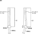
図4は、照明部17での照明方向の調整の例を説明する図である。 FIG. 4 is a diagram for explaining an example of adjustment of the illumination direction in the illumination unit 17.
図4では、照明部17において、図示せぬ光源から発せられた照明光が、内視鏡スコープ22内に設けられたライトガイドケーブルを通って、内視鏡スコープ22の先端に設けられた照明窓に到達し、その照明窓から照射される。
In FIG. 4, in the illumination unit 17, illumination light emitted from a light source (not shown) passes through a light guide cable provided in the
図4において、照明窓は、内視鏡スコープ22の先端の正面としての円上の、半径に垂直な方向を回転軸として回動(揺動)するように構成されている。照明窓が回動することで、照明光の照明方向が、例えば、軟性鏡のように、中心方向や周辺方向に調整される。
In FIG. 4, the illumination window is configured to rotate (swing) around a circle as a front surface of the distal end of the
図4では、照明光が、常時照射され、照明窓の回動による照明方向の調整が、フレームごとに行われる。これにより、偶数フレームの内視鏡画像の撮影時には、照明窓から、照明方向が中心方向の照明光が照射され、奇数フレームの内視鏡画像の撮影時には、照明方向が周辺方向の照明光が照射される。 In FIG. 4, illumination light is always irradiated, and adjustment of the illumination direction by rotation of the illumination window is performed for each frame. Thus, when an endoscopic image of an even frame is captured, illumination light having a central illumination direction is emitted from the illumination window, and when an endoscopic image of an odd frame is captured, illumination light having an illumination direction of the peripheral direction is emitted. Irradiated.
<合成処理> <Compositing process>
図5は、図1の信号処理部13で行われる合成処理の概要を説明する図である。
FIG. 5 is a diagram illustrating an outline of the synthesis process performed by the
合成処理では、偶数フレームの内視鏡画像と、奇数フレームの内視鏡画像とが合成される。 In the synthesizing process, the endoscopic image of the even frame and the endoscopic image of the odd frame are synthesized.
上述したように、偶数フレームの内視鏡画像の撮影時には、中心方向の照明光が照射され、奇数フレームの内視鏡画像の撮影時には、周辺方向の照明光が照射される。 As described above, illumination light in the center direction is irradiated when an endoscopic image of an even frame is captured, and illumination light in a peripheral direction is irradiated when an endoscopic image of an odd frame is captured.
その結果、偶数フレームでは、内視鏡画像の中心部分に、照明光が集中し、奇数フレームでは、内視鏡画像の周辺部分に、照明光が分散する。 As a result, the illumination light is concentrated on the central portion of the endoscopic image in the even frame, and the illumination light is dispersed in the peripheral portion of the endoscopic image in the odd frame.
したがって、偶数フレームの内視鏡画像では、中心部分の領域A-1が明るく、周辺部分の領域A-2が、中心部分の領域A-1に比較して暗くなる。また、奇数フレームの内視鏡画像では、周辺部分の領域B-2が明るく、中心部分の領域B-1が、周辺部分の領域B-2に比較して暗くなる。 Therefore, in the endoscopic image of the even frame, the central area A-1 is bright and the peripheral area A-2 is darker than the central area A-1. In the endoscopic image of the odd-numbered frame, the peripheral area B-2 is bright and the central area B-1 is darker than the peripheral area B-2.
偶数フレームの内視鏡画像の中心部分の領域A-1については、照明光の光軸と、イメージセンサ11Aの光軸とが近くなるため、鏡面反射光成分が含まれやすい。
In the region A-1 at the center of the even-numbered endoscopic image, the optical axis of the illumination light and the optical axis of the
一方、偶数フレームの内視鏡画像の周辺部分の領域A-2、並びに、奇数フレームの内視鏡画像の中心部分の領域B-1、及び、周辺部分の領域B-2(奇数フレームの内視鏡画像の全領域)については、照明光の光軸と、イメージセンサ11Aの光軸とのずれが大になるため、鏡面反射光成分が含まれにくい。
On the other hand, a region A-2 in the peripheral portion of the endoscopic image in the even frame, a region B-1 in the central portion of the endoscopic image in the odd frame, and a region B-2 in the peripheral portion (inside the odd frame) With respect to the entire region of the endoscopic image, the difference between the optical axis of the illumination light and the optical axis of the
合成処理では、以上のような偶数フレームの内視鏡画像と、奇数フレームの内視鏡画像とを、適切に合成することで、鏡面反射光成分が抑制された(鏡面反射光成分がない)合成画像が生成される。 In the synthesizing process, the specular reflected light component is suppressed (there is no specular reflected light component) by appropriately combining the endoscopic image of the even frame and the endoscopic image of the odd frame as described above. A composite image is generated.
さらに、偶数フレームの内視鏡画像と、奇数フレームの内視鏡画像とは、露光条件が異なる撮影画像であるため、そのような偶数フレームの内視鏡画像と、奇数フレームの内視鏡画像とを合成することで、HDR(High Dynamic Range)の効果を得ることができる。 Further, since the even-frame endoscopic image and the odd-frame endoscopic image are captured images having different exposure conditions, such an even-frame endoscopic image and an odd-frame endoscopic image Can be combined to obtain an HDR (High Dynamic Range) effect.
すなわち、偶数フレームの内視鏡画像と、奇数フレームの内視鏡画像との合成処理によれば、高ダイナミックレンジの合成画像を生成することができる。 That is, according to the synthesis process of the endoscopic image of the even frame and the endoscopic image of the odd frame, a synthesized image with a high dynamic range can be generated.
ここで、中心方向の照明光が照射されて撮影される偶数フレームの内視鏡画像を、以下、中心照射画像ともいう。また、周辺方向の照明光が照射されて撮影される奇数フレームの内視鏡画像を、以下、周辺照射画像ともいう。 Here, an even-numbered endoscope image captured by irradiation with illumination light in the central direction is hereinafter also referred to as a central irradiation image. In addition, an endoscopic image of an odd-numbered frame that is captured by being irradiated with illumination light in the peripheral direction is hereinafter also referred to as a peripheral irradiation image.
図6は、中心照射画像と周辺照射画像とのそれぞれの露光量及びゲインの例を示す図である。 FIG. 6 is a diagram illustrating examples of exposure amounts and gains of the center irradiation image and the peripheral irradiation image.
図6のAは、中心照射画像と周辺照射画像のそれぞれの露光量(の分布)の例を示している。 FIG. 6A shows an example of the exposure amount (distribution) of each of the central irradiation image and the peripheral irradiation image.
図6のAにおいて、横軸は、中心照射画像及び周辺照射画像の水平方向又は垂直方向の位置(座標)を表し、縦軸は、露光量(明るさ)を表す。 In FIG. 6A, the horizontal axis represents the horizontal or vertical position (coordinates) of the central irradiation image and the peripheral irradiation image, and the vertical axis represents the exposure amount (brightness).
中心照射画像は、その中心照射画像の中心部分に向かう照明方向の照明光が被写体に照射され、撮影が行われた画像であるため、中心部分の露光量が大になり、周辺部分の露光量が小になる。 The central irradiation image is an image that is shot by illuminating the subject with illumination light in the direction of illumination toward the central portion of the central irradiation image, so the exposure amount of the central portion becomes large, and the exposure amount of the peripheral portion Becomes small.
一方、周辺照射画像は、その周辺照射画像の周辺部分に向かう照明方向の照明光が被写体に照射され、撮影が行われた画像であるため、中心部分の露光量が小になり、周辺部分の露光量が大になる。 On the other hand, the peripheral illumination image is an image obtained by irradiating the subject with illumination light in the illumination direction toward the peripheral portion of the peripheral illumination image, and thus the exposure amount of the central portion is small, and the peripheral portion The amount of exposure increases.
なお、中心照射画像の露光量は、任意の方法で測定することができる。 The exposure amount of the center irradiation image can be measured by an arbitrary method.
また、中心照射画像の露光量は、例えば、中心方向の照明を被写体に照射して撮影を行うシミュレーション等によってあらかじめ求めておくことができる。 Further, the exposure amount of the center irradiation image can be obtained in advance by, for example, a simulation in which photographing is performed by irradiating the subject with illumination in the center direction.
中心照射画像の露光量を、シミュレーション等によってあらかじめ求めておく場合には、1種類の露光量(の分布)を求めておくことの他、例えば、被写体と、内視鏡スコープ22との距離に対応した複数種類の露光量を求めておくことができる。
When the exposure amount of the center irradiation image is obtained in advance by simulation or the like, in addition to obtaining one type of exposure amount (distribution thereof), for example, the distance between the subject and the
被写体と、内視鏡スコープ22との距離に対応した複数種類の露光量を求めておく場合には、内視鏡システムの使用時に、被写体と、内視鏡スコープ22との実際の距離を計測し、その実際の距離に対応する露光量を、中心照射画像の露光量として用いることができる。
When a plurality of types of exposure amounts corresponding to the distance between the subject and the
以上の点、周辺照射画像の露光量についても、同様である。 The same applies to the above points and the exposure amount of the peripheral irradiation image.
中心照射画像、及び、周辺照射画像の露光量は、位置(画素)によって異なるため、信号処理部13は、中心照射画像と周辺照射画像とを合成するにあたって、露光量を一様にするために、中心照射画像、及び、周辺照射画像の、例えば、画素ごとに適切なゲインをかける。
Since the exposure amount of the central irradiation image and the peripheral irradiation image differs depending on the position (pixel), the
すなわち、信号処理部13は、例えば、中心照射画像の露光量から、最大の露光量を検出し、その最大の露光量を基準として、中心照射画像、及び、周辺照射画像それぞれの各画素に、その画素の露光量に応じたゲインをかける。
That is, for example, the
具体的には、信号処理部13は、中心照射画像の最大の露光量の画素のゲインを1.0に設定する。そして、信号処理部13は、中心照射画像の最大の露光量の画素のゲインを基準として、中心照射画像、及び、周辺照射画像それぞれの各画素に、その画素の露光量に反比例するような値のゲインを設定する。
Specifically, the
図6のBは、中心照射画像と周辺照射画像のそれぞれに設定されたゲイン(の分布)の例を示している。 FIG. 6B shows an example of the gain (distribution) set for each of the central irradiation image and the peripheral irradiation image.
図6のBにおいて、横軸は、中心照射画像及び周辺照射画像の水平方向又は垂直方向の位置を表し、縦軸は、信号処理部13で設定されるゲインを表す。
6B, the horizontal axis represents the horizontal or vertical position of the central irradiation image and the peripheral irradiation image, and the vertical axis represents the gain set by the
図6のBにおいて、中心照射画像、及び、周辺照射画像それぞれの各画素のゲインは、その画素の露光量に反比例するような値になっている。 In FIG. 6B, the gain of each pixel of each of the central irradiation image and the peripheral irradiation image is a value that is inversely proportional to the exposure amount of the pixel.
信号処理部13は、中心照射画像及び周辺照射画像にゲインをかけ、そのゲインをかけた後の中心照射画像と周辺照射画像とを合成する。
The
すなわち、いま、注目する注目位置の中心照射画像及び周辺照射画像の画素値を、それぞれ、Pc及びPoと表すこととする。また、中心照射画像及び周辺照射画像の注目位置の画素のゲイン(画素に設定されたゲイン)を、それぞれ、Gc及びGoと表すこととする。 That is, the pixel values of the center irradiation image and the peripheral irradiation image at the target position of interest are now expressed as Pc and Po, respectively. In addition, the gain of the pixel at the target position in the central irradiation image and the peripheral irradiation image (gain set for the pixel) is expressed as Gc and Go, respectively.
この場合、ゲインをかけた後の中心照射画像及び周辺照射画像の注目位置の画素の画素値Vc及びVoは、それぞれ、式Vc=Pc・Gc、及び、式Vo=Po・Goで表される。 In this case, the pixel values Vc and Vo of the pixel at the target position of the central irradiation image and the peripheral irradiation image after gain are expressed by the expressions Vc = Pc · Gc and Vo = Po · Go, respectively. .
信号処理部13は、例えば、ゲインをかけた後の中心照射画像及び周辺照射画像それぞれの注目位置の画素の画素値Vc及びVoの重み付け加算値を、合成画像の注目位置の画素の画素値Cとして求める。
For example, the
すなわち、いま、画素値Vc及びVoの重み付け加算値を求めるのに用いる重みを、aと表すこととすると、信号処理部13は、例えば、式C=a・Vc+(1-a)・Voに従って、合成画像の注目位置の画素の画素値Cを求める。
That is, if the weight used to calculate the weighted addition value of the pixel values Vc and Vo is represented as a, the
但し、信号処理部13は、例えば、(ゲインをかけた後の)中心照射画像又は周辺照射画像それぞれの注目位置の画素の画素値Vc又はVoに基づいて、式0.0=<a=<1.0で表される範囲の値を、重みaとして設定する。
However, the
図7は、重みaの設定の例を示す図である。 FIG. 7 is a diagram illustrating an example of setting the weight a.
図7において、横軸は、中心照射画像又は周辺照射画像の注目位置の画素の画素値Vc又はVoを表し、縦軸は、重みaを表す。 In FIG. 7, the horizontal axis represents the pixel value Vc or Vo of the pixel at the target position of the central irradiation image or the peripheral irradiation image, and the vertical axis represents the weight a.
中心照射画像の注目位置の画素の露光量が、周辺照射画像の注目位置の画素の露光量より大である場合、図7のAに示すように、重みaは、中心照射画像の注目位置の画素の画素値Vcに応じて設定される。 When the exposure amount of the pixel at the target position in the central irradiation image is larger than the exposure amount of the pixel at the target position in the peripheral irradiation image, as shown in FIG. It is set according to the pixel value Vc of the pixel.
また、中心照射画像の注目位置の画素の露光量が、周辺照射画像の注目位置の画素の露光量より大でない場合、図7のBに示すように、重みaは、周辺照射画像の注目位置の画素の画素値Voに応じて設定される。 Further, when the exposure amount of the pixel at the target position of the central irradiation image is not larger than the exposure amount of the pixel at the target position of the peripheral irradiation image, as shown in FIG. 7B, the weight a is the target position of the peripheral irradiation image. It is set according to the pixel value Vo of this pixel.
ここで、図7のAでは、重みaは、中心照射画像の注目位置の画素の画素値Vcの増加に対して、1.0から減少する特性を有する。ここでの減少は、減少量が0以上の減少を意味する。 Here, in A of FIG. 7, the weight a has a characteristic of decreasing from 1.0 with respect to the increase of the pixel value Vc of the pixel at the target position of the central irradiation image. The reduction here means a reduction in which the reduction amount is 0 or more.
また、図7のBでは、重みaは、周辺照射画像の注目位置の画素の画素値Voの増加に対して、0.0から増加する特性を有する。ここでの増加とは、増加量が0以上の増加を意味する。 In FIG. 7B, the weight a has a characteristic of increasing from 0.0 with respect to an increase in the pixel value Vo of the pixel at the target position in the peripheral irradiation image. The increase here means an increase of 0 or more.
図7のAでは、中心照射画像の注目位置の画素の画素値Vcが閾値THより小さい(又は、以下である)場合、重みaは、1に設定される。また、図7のAでは、中心照射画像の注目位置の画素の画素値Vcが閾値TH以上である(又は、より大きい)場合、重みaは、0に設定される。 In A of FIG. 7, the weight a is set to 1 when the pixel value Vc of the pixel at the target position in the center irradiation image is smaller than (or less than) the threshold value TH. In FIG. 7A, the weight a is set to 0 when the pixel value Vc of the pixel at the target position of the central irradiation image is equal to or greater than (or larger than) the threshold value TH.
図7のBでは、周辺照射画像の注目位置の画素の画素値Voが閾値THより小さい場合、重みaは、0に設定される。また、図7のBでは、周辺照射画像の注目位置の画素の画素値Voが閾値TH以上である場合、重みaは、1に設定される。 In B of FIG. 7, the weight a is set to 0 when the pixel value Vo of the pixel at the target position in the peripheral irradiation image is smaller than the threshold value TH. In FIG. 7B, the weight a is set to 1 when the pixel value Vo of the pixel at the target position in the peripheral irradiation image is equal to or greater than the threshold value TH.
閾値THとしては、例えば、鏡面反射光成分を含む可能性が高い画素の画素値の最小値等を用いることができる。かかる閾値THは、例えば、シミュレーション等により推定することができる。 As the threshold value TH, for example, the minimum pixel value of a pixel that is highly likely to include a specular reflection light component can be used. Such a threshold TH can be estimated by, for example, simulation.
重みaとして、上述のように、0又は1が設定される場合、式C=a・Vc+(1-a)・Voに従って行われる合成処理では、実質的に、中心照射画像及び周辺照射画像の注目位置の画素の画素値Vc及びVoのうちの一方の画素値が、合成画像の注目位置の画素値となる。 When 0 or 1 is set as the weight a as described above, the composition processing performed according to the formula C = a · Vc + (1−a) · Vo is substantially equivalent to the central irradiation image and the peripheral irradiation image. One of the pixel values Vc and Vo of the pixel at the target position is the pixel value at the target position of the composite image.
すなわち、中心照射画像の注目位置の画素の露光量が、周辺照射画像の注目位置の画素の露光量より大である場合(図7のA)、中心照射画像の注目位置の画素の画素値Vcが、閾値THより小であるときには、重みaが1となり、中心照射画像の注目位置の画素の画素値Vcが、合成画像の注目位置の画素の画素値Cとして求められる。また、中心照射画像の注目位置の画素の画素値Vcが、閾値THより小でないときには、重みaが0となり、周辺照射画像の注目位置の画素の画素値Voが、合成画像の注目位置の画素の画素値Cとして求められる。 That is, when the exposure amount of the pixel at the target position in the central irradiation image is larger than the exposure amount of the pixel at the target position in the peripheral irradiation image (A in FIG. 7), the pixel value Vc of the pixel at the target position in the central irradiation image. However, when the value is smaller than the threshold value TH, the weight a is 1, and the pixel value Vc of the pixel at the target position of the central irradiation image is obtained as the pixel value C of the pixel at the target position of the composite image. Further, when the pixel value Vc of the pixel at the target position in the central irradiation image is not smaller than the threshold value TH, the weight a is 0, and the pixel value Vo of the pixel at the target position in the peripheral irradiation image is the pixel at the target position in the composite image. Is obtained as a pixel value C.
一方、中心照射画像の注目位置の画素の露光量が、周辺照射画像の注目位置の画素の露光量より大でない場合(図7のB)、周辺照射画像の注目位置の画素の画素値Voが、閾値THより小であるときには、重みaが0となり、周辺照射画像の注目位置の画素の画素値Voが、合成画像の注目位置の画素の画素値Cとして求められる。また、周辺照射画像の注目位置の画素の画素値Voが、閾値THより小でないときには、重みaが1となり、中心照射画像の注目位置の画素の画素値Vcが、合成画像の注目位置の画素の画素値Cとして求められる。 On the other hand, when the exposure amount of the pixel at the target position in the central irradiation image is not larger than the exposure amount of the pixel at the target position in the peripheral irradiation image (B in FIG. 7), the pixel value Vo of the pixel at the target position in the peripheral irradiation image is When the value is smaller than the threshold TH, the weight a is 0, and the pixel value Vo of the pixel at the target position in the peripheral irradiation image is obtained as the pixel value C of the pixel at the target position in the synthesized image. Further, when the pixel value Vo of the pixel at the target position in the peripheral irradiation image is not smaller than the threshold TH, the weight a is 1, and the pixel value Vc of the pixel at the target position in the central irradiation image is the pixel at the target position in the composite image. Is obtained as a pixel value C.
ここで、注目位置が、内視鏡画像(中心照射画像及び周辺照射画像)の中心部分である場合には、中心照射画像の注目位置の画素の露光量が、周辺照射画像の注目位置の画素の露光量より大になる。この場合、中心照射画像の注目位置の画素の画素値Vcが、閾値THより小であるときには、中心照射画像の注目位置の画素の画素値Vcが、鏡面反射光成分を含まないと推定され、その画素値Vcが、そのまま、合成画像の注目位置の画素の画素値Cとなる。 Here, when the target position is the central part of the endoscopic image (the central irradiation image and the peripheral irradiation image), the exposure amount of the pixel at the target position in the central irradiation image is the pixel at the target position in the peripheral irradiation image. The exposure amount becomes larger. In this case, when the pixel value Vc of the pixel at the target position of the central irradiation image is smaller than the threshold value TH, it is estimated that the pixel value Vc of the pixel at the target position of the central irradiation image does not include the specular reflection component. The pixel value Vc is directly used as the pixel value C of the pixel at the target position in the composite image.
また、中心照射画像の注目位置の画素の画素値Vcが、閾値THより小でないときには、中心照射画像の注目位置の画素の画素値Vcが、鏡面反射光成分が含む可能性があると推定され、周辺照射画像の注目位置の画素の画素値Voが、合成画像の注目位置の画素の画素値Cとなる。 In addition, when the pixel value Vc of the pixel at the target position in the center irradiation image is not smaller than the threshold TH, it is estimated that the pixel value Vc of the pixel at the target position in the center irradiation image may include a specular reflection component. The pixel value Vo of the pixel at the target position in the peripheral irradiation image becomes the pixel value C of the pixel at the target position in the synthesized image.
一方、注目位置が、周辺部分である場合には、周辺照射画像の注目位置の画素の露光量が、中心照射画像の注目位置の画素の露光量より大になる。この場合、周辺照射画像の注目位置の画素の画素値Voが、閾値THより小であるときには、周辺照射画像の注目位置の画素の画素値Voが、鏡面反射光成分を含まないと推定され、その画素値Voが、そのまま、合成画像の注目位置の画素の画素値Cとなる。 On the other hand, when the target position is the peripheral portion, the exposure amount of the pixel at the target position in the peripheral irradiation image is larger than the exposure amount of the pixel at the target position in the central irradiation image. In this case, when the pixel value Vo of the pixel at the target position of the peripheral irradiation image is smaller than the threshold TH, the pixel value Vo of the pixel at the target position of the peripheral irradiation image is estimated not to include a specular reflection component, The pixel value Vo becomes the pixel value C of the pixel at the target position of the composite image as it is.
また、周辺照射画像の注目位置の画素の画素値V0が、閾値THより小でないときには、周辺照射画像の注目位置の画素の画素値V0が、鏡面反射光成分が含む可能性があると推定され、中心照射画像の注目位置の画素の画素値VCが、合成画像の注目位置の画素の画素値Cとなる。 In addition, when the pixel value V 0 of the pixel at the target position in the peripheral irradiation image is not smaller than the threshold value TH, the pixel value V 0 of the pixel at the target position in the peripheral irradiation image may include the specular reflection component. The estimated pixel value V C of the pixel at the target position in the central irradiation image becomes the pixel value C of the pixel at the target position in the composite image.
鏡面反射は、内視鏡画像の中心部分に映る被写体において、露光量が大きい場合に生じやすく、そのため、中心照射画像の中心部分の画素の画素値Vc(Pc)が、飽和値、又は、飽和値に非常に近い値になっている場合に、その画素値Vcに、鏡面反射光成分が含まれる可能性が高い。 Specular reflection is likely to occur when the exposure amount is large in the subject that appears in the center part of the endoscopic image, and therefore the pixel value Vc (Pc) of the pixel in the center part of the center irradiation image is saturated or saturated. When the value is very close to the value, the pixel value Vc is likely to contain a specular reflection light component.
したがって、上述のように、中心照射画像の注目位置の画素の露光量が(周辺照射画像の注目位置の画素の露光量より)大である場合において、中心照射画像の注目位置の画素の画素値Vcが閾値THより小でないときに、信号処理部13において、中心照射画像の注目位置の画素の画素値Vcが、鏡面反射光成分が含む可能性があると推定し、周辺照射画像の注目位置の画素の画素値Voを、合成画像の注目位置の画素の画素値Cとすることにより、内視鏡画像から鏡面反射光成分を検出せずに、鏡面反射光成分を抑制した合成画像を得ることができる。
Therefore, as described above, when the exposure amount of the pixel at the target position of the central irradiation image is larger (than the exposure amount of the pixel at the target position of the peripheral irradiation image), the pixel value of the pixel at the target position of the central irradiation image When Vc is not smaller than the threshold TH, the
なお、図7では、中心照射画像の注目位置の画素の露光量が、周辺照射画像の注目位置の画素の露光量より大である場合において、中心照射画像の注目位置の画素の画素値Vcが、閾値THより小でないときには、その画素値Vcが、鏡面反射光成分が含む可能性があると推定され、周辺照射画像の注目位置の画素の画素値Voが、合成画像の注目位置の画素の画素値Cとして求められる。 In FIG. 7, when the exposure amount of the pixel at the target position in the central irradiation image is larger than the exposure amount of the pixel at the target position in the peripheral irradiation image, the pixel value Vc of the pixel at the target position in the central irradiation image is When the pixel value Vc is not smaller than the threshold TH, it is estimated that the specular reflection light component may include the specular reflection light component, and the pixel value Vo of the target position pixel of the peripheral irradiation image is equal to that of the target position pixel of the composite image. It is obtained as a pixel value C.
また、中心照射画像の注目位置の画素の露光量が、周辺照射画像の注目位置の画素の露光量より大でない場合において、周辺照射画像の注目位置の画素の画素値Voが、閾値THより小でないときには、その画素値Voが、鏡面反射光成分が含む可能性があると推定され、中心照射画像の注目位置の画素の画素値Vcが、合成画像の注目位置の画素の画素値Cとして求められる。 In addition, when the exposure amount of the pixel at the target position in the central irradiation image is not larger than the exposure amount of the pixel at the target position in the peripheral irradiation image, the pixel value Vo of the pixel at the target position in the peripheral irradiation image is smaller than the threshold value TH. If not, it is estimated that the pixel value Vo may be included in the specular reflection light component, and the pixel value Vc of the pixel at the target position in the center irradiation image is obtained as the pixel value C of the pixel at the target position in the composite image. It is done.
しかしながら、中心照射画像の注目位置の画素の露光量が、周辺照射画像の注目位置の画素の露光量より大である場合において、中心照射画像の注目位置の画素の画素値Vcが、閾値THより小であるときであっても、その画素値Vcが、鏡面反射光成分が含むことがあり得る。 However, when the exposure amount of the pixel at the target position in the central irradiation image is larger than the exposure amount of the pixel at the target position in the peripheral irradiation image, the pixel value Vc of the pixel at the target position in the central irradiation image is greater than the threshold value TH. Even when it is small, the specular reflection light component may be included in the pixel value Vc.
同様に、中心照射画像の注目位置の画素の露光量が、周辺照射画像の注目位置の画素の露光量より大でない場合において、周辺照射画像の注目位置の画素の画素値Voが、閾値THより小であるときであっても、その画素値Voが、鏡面反射光成分が含むことがあり得る。 Similarly, when the exposure amount of the pixel at the target position in the central irradiation image is not larger than the exposure amount of the pixel at the target position in the peripheral irradiation image, the pixel value Vo of the pixel at the target position in the peripheral irradiation image is greater than the threshold value TH. Even when it is small, the specular reflection light component may be included in the pixel value Vo.
そこで、信号処理部13では、中心照射画像及び周辺照射画像それぞれの注目位置の画素について、鏡面反射光成分を検出する処理、すなわち、例えば、二色性反射モデル等を用いた鏡面反射光成分の検出の処理等を行うことができる。そして、中心照射画像及び周辺照射画像それぞれの注目位置の画素のうちのいずれか一方の画素について、鏡面反射光成分が検出された場合には、重みaを用いた重み付け加算値に代えて、他方の画素の画素値を、合成画像の注目位置の画素の画素値Cに採用することができる。
Therefore, the
また、上述の場合には、重みaを、0又は1に設定する(閾値THにおいて、0又は1から、1又は0に急峻に変化する値に設定する)こととしたが、重みaは、中心照射画像又は周辺照射画像それぞれの注目位置の画素の画素値Vc又はVoに基づいて、式0.0=<a=<1.0で表される範囲の任意の値に設定することができる。 In the above case, the weight a is set to 0 or 1 (the threshold TH is set to a value that sharply changes from 0 or 1 to 1 or 0), but the weight a is Based on the pixel value Vc or Vo of the pixel at the target position in each of the central irradiation image and the peripheral irradiation image, an arbitrary value in the range represented by the expression 0.0 = <a = <1.0 can be set.
すなわち、重みaは、例えば、画素値Vc又はVoが閾値THの近傍の値である場合には、図7に点線で示すように、画素値Vc又はVoに応じて、1から0に緩やか変化する値、又は、0から1に緩やかに変化する値に設定することができる。 That is, for example, when the pixel value Vc or Vo is a value in the vicinity of the threshold value TH, the weight a gradually changes from 1 to 0 according to the pixel value Vc or Vo as shown by a dotted line in FIG. Or a value that gradually changes from 0 to 1.
例えば、重みaは、図7に点線で示すように、TH1(<TH)からTH2(>TH)の範囲の画素値Vc又はVoに対しては、その画素値Vc又はVoに応じて、1から0に緩やか変化する値、又は、0から1に緩やかに変化する値に設定することができる。 For example, as indicated by a dotted line in FIG. 7, the weight a is 1 for a pixel value Vc or Vo in a range from TH1 (<TH) to TH2 (> TH), depending on the pixel value Vc or Vo. A value that gradually changes from 0 to 0 or a value that gradually changes from 0 to 1 can be set.
この場合、合成画像の注目位置の画素の画素値Cは、画素値VcとVoとを、重みaに対応する割合(画素値Vc又はVoと閾値THとの差に対応する割合)でブレンドした値となる。 In this case, the pixel value C of the pixel at the target position in the composite image is a blend of the pixel values Vc and Vo at a ratio corresponding to the weight a (a ratio corresponding to the difference between the pixel value Vc or Vo and the threshold value TH). Value.
その他、重みaとしては、画素値Vcの増加に対して、1から減少する任意の特性、又は、画素値Voの増加に対して、0から増加する任意の特性を採用することができる。 In addition, as the weight a, any characteristic that decreases from 1 as the pixel value Vc increases, or any characteristic that increases from 0 as the pixel value Vo increases can be adopted.
合成処理では、以上のようにして、偶数フレームの内視鏡画像と、奇数フレームの内視鏡画像とが合成され、合成画像が生成されると、その合成画像の階調が圧縮される。 In the synthesizing process, as described above, the endoscopic image of the even frame and the endoscopic image of the odd frame are synthesized, and when the synthesized image is generated, the gradation of the synthesized image is compressed.
すなわち、合成処理では、中心照射画像及び周辺照射画像にゲインがかけられ、そのゲインがかけられた後の中心照射画像と周辺照射画像とが合成される。そのため、合成画像は、合成処理前の中心照射画像や周辺照射画像よりもビット幅が大きい画像、つまり、ダイナミックレンジが高い画像になっている。 That is, in the synthesis process, a gain is applied to the central irradiation image and the peripheral irradiation image, and the central irradiation image and the peripheral irradiation image after the gain is applied are combined. For this reason, the composite image is an image having a larger bit width than the central irradiation image and the peripheral irradiation image before the synthesis processing, that is, an image having a high dynamic range.
例えば、中心照射画像及び周辺照射画像にかけられたゲインの最大値が、16.0(=24)である場合には、合成画像のビット幅は、合成処理前の中心照射画像や周辺照射画像のビット幅よりも4ビットだけ多くなる。 For example, when the maximum value of the gain applied to the center irradiation image and the peripheral irradiation image is 16.0 (= 2 4 ), the bit width of the composite image is the bit of the center irradiation image or the peripheral irradiation image before the synthesis processing. 4 bits more than the width.
合成処理では、合成画像のビット幅を、例えば、合成処理前の中心照射画像や周辺照射画像のビット幅に一致させるように、合成画像の階調が圧縮される。 In the synthesis process, the gradation of the synthesized image is compressed so that the bit width of the synthesized image matches, for example, the bit width of the central irradiation image and the peripheral irradiation image before the synthesis process.
合成画像の階調を圧縮する方法としては、例えば、固定のトーンカーブを用いて階調を圧縮する方法や、画像の特徴量に応じてトーンカーブを切り替えて階調を圧縮する方法を採用することができる。さらに、合成画像の階調を圧縮する方法としては、例えば、中心照射画像及び周辺照射画像にかけたゲインの最大値で除算を行う方法や、その他の任意の方法を採用することができる。 As a method of compressing the gradation of the composite image, for example, a method of compressing the gradation using a fixed tone curve or a method of compressing the gradation by switching the tone curve according to the feature amount of the image is adopted. be able to. Furthermore, as a method of compressing the gradation of the composite image, for example, a method of dividing by the maximum value of the gain applied to the central irradiation image and the peripheral irradiation image, or any other arbitrary method can be employed.
図8は、図1の信号処理部13で行われる合成処理のタイミングの例を説明する図である。
FIG. 8 is a diagram illustrating an example of the timing of the synthesis process performed by the
図8では、合成処理において、ある偶数フレーム#2Nの内視鏡画像(中心照射画像)と、その偶数フレーム#2Nの次の奇数フレーム#2N+1の内視鏡画像(周辺照射画像)とが合成される。さらに、合成処理では、その後、奇数フレーム#2N+1の次の偶数フレーム#2N+2の内視鏡画像(中心照射画像)と、その偶数フレーム#2N+2の次の奇数フレーム#2N+3の内視鏡画像(周辺照射画像)とが合成される。
In FIG. 8, in the synthesis process, an endoscope image (center irradiation image) of a certain even
図8の合成処理では、以上のような、偶数フレームの内視鏡画像(中心照射画像)と奇数フレームの内視鏡画像(周辺照射画像)との合成が繰り返される。 In the combining process of FIG. 8, the above-described combining of the even-numbered endoscope image (center irradiation image) and the odd-numbered endoscope image (peripheral irradiation image) is repeated.
この場合、偶数フレームの内視鏡画像と奇数フレームの内視鏡画像との合成により得られる合成画像のフレームレートは、内視鏡11で撮影される内視鏡画像のフレームレートの1/2になる。
In this case, the frame rate of the composite image obtained by combining the endoscopic image of the even frame and the endoscopic image of the odd frame is 1/2 of the frame rate of the endoscopic image photographed by the
したがって、合成処理を、図8に示したタイミングで行う場合には、内視鏡11において、合成画像に要求されるフレームレートの2倍のフレームレートで、内視鏡画像を撮影する必要がある。
Therefore, when the synthesizing process is performed at the timing shown in FIG. 8, it is necessary for the
図9は、図1の信号処理部13で行われる合成処理のタイミングの他の例を説明する図である。
FIG. 9 is a diagram illustrating another example of the timing of the synthesis process performed by the
図9では、合成処理において、ある偶数フレーム#2Nの内視鏡画像(中心照射画像)と、その偶数フレーム#2Nの次の奇数フレーム#2N+1の内視鏡画像(周辺照射画像)とが合成される。さらに、合成処理では、その後、直前の合成に用いられた奇数フレーム#2N+1の内視鏡画像(周辺照射画像)と、その奇数フレーム#2N+1の次の偶数フレーム#2N+2の内視鏡画像(中心照射画像)とが合成される。
In FIG. 9, in the composition process, an endoscopic image (center irradiation image) of a certain even
図9の合成処理では、以上のような、偶数フレームの内視鏡画像(中心照射画像)と奇数フレームの内視鏡画像(周辺照射画像)との合成が繰り返される。 In the composition process of FIG. 9, the composition of the endoscope image (center irradiation image) of the even frame and the endoscope image (peripheral irradiation image) of the odd frame is repeated as described above.
この場合、偶数フレームの内視鏡画像と奇数フレームの内視鏡画像との合成により得られる合成画像のフレームレートは、内視鏡11で撮影される内視鏡画像のフレームレートに一致する。
In this case, the frame rate of the composite image obtained by combining the endoscopic image of the even frame and the endoscopic image of the odd frame matches the frame rate of the endoscopic image captured by the
<内視鏡システムの処理> <Endoscope system processing>
図10は、図1の内視鏡システムの処理の例を説明するフローチャートである。 FIG. 10 is a flowchart illustrating an example of processing of the endoscope system of FIG.
なお、図10では、例えば、合成処理が、図8に示したタイミングで行われることとする。 In FIG. 10, for example, the synthesis process is performed at the timing shown in FIG.
ステップS11において、これから内視鏡11で撮影しようとしている注目フレームに適した照明の制御が行われる。
In step S11, illumination control suitable for the frame of interest that is going to be taken by the
すなわち、ステップS11では、撮影制御部15は、注目フレームに適した照明条件を設定し、照明制御部16に供給する。照明制御部16は、被写体が撮影制御部15からの照明条件に従って照明されるように、照明部17を制御する。
That is, in step S <b> 11, the imaging control unit 15 sets illumination conditions suitable for the frame of interest and supplies them to the
照明部17は、照明制御部16の制御に従って、照明方向が中心方向又は周辺方向の照明光を照射することにより、被写体を照明する。
The illumination unit 17 illuminates the subject by irradiating illumination light whose illumination direction is the central direction or the peripheral direction according to the control of the
その後、処理は、ステップS11からステップS12に進み、内視鏡11は、照明部17によって照明光が照射された被写体を撮影し、これにより、注目フレームの内視鏡画像を取得して、処理は、ステップS13に進む。
Thereafter, the process proceeds from step S11 to step S12, and the
ステップS13では、撮影制御部15は、内視鏡11において、1フレームの合成画像の合成に必要な内視鏡画像の撮影が完了しているかどうかを判定する。
In step S <b> 13, the imaging control unit 15 determines whether or not the
ステップS13において、1フレームの合成画像の合成に必要な内視鏡画像の撮影が、まだ完了していないと判定された場合、処理は、ステップS14に進む。 In step S13, when it is determined that the imaging of the endoscopic image necessary for synthesizing the synthesized image of one frame has not yet been completed, the process proceeds to step S14.
ステップS14では、撮影制御部15は、内視鏡11で撮影された注目フレームの内視鏡画像を、内視鏡11からメモリ12に供給させて書き込む(記憶させる)。そして、処理は、ステップS14からステップS11に戻り、現在の注目フレームの次のフレームを、新たに注目フレームとして、以下、同様の処理が繰り返される。
In step S <b> 14, the imaging control unit 15 supplies the endoscope image of the frame of interest captured by the
また、ステップS13において、1フレームの合成画像の合成に必要な内視鏡画像の撮影が完了したと判定された場合、撮影制御部15は、内視鏡11で撮影された注目フレームの内視鏡画像を、内視鏡11から信号処理部13に供給させる。
If it is determined in step S <b> 13 that the imaging of the endoscopic image necessary for synthesizing the composite image of one frame has been completed, the imaging control unit 15 performs the endoscopic observation of the frame of interest captured by the
そして、処理は、ステップS13からステップ15に進み、信号処理部13は、内視鏡11から直前に供給された注目フレームの内視鏡画像と、メモリ12に記憶された、注目フレームの直前のフレームの内視鏡画像とを合成する合成処理を行う。
Then, the process proceeds from step S 13 to step 15, and the
すなわち、いま、注目フレームの内視鏡画像が、周辺照射画像であるとすると、メモリ12には、その周辺照射画像の直前のフレームの中心照射画像が記憶されており、合成処理では、その中心照射画像と周辺照射画像とが合成され、合成画像が生成される。
That is, if the endoscope image of the frame of interest is a peripheral irradiation image, the
合成処理によって得られる合成画像は、信号処理部13から表示部14に供給されて表示され、これにより、1フレームの合成画像を表示する処理が終了する。
The synthesized image obtained by the synthesizing process is supplied from the
次のフレームの合成画像を表示する場合には、図10のフローチャートに従った処理が繰り返される。 When displaying the composite image of the next frame, the process according to the flowchart of FIG. 10 is repeated.
図11は、図10のステップS15で行われる合成処理の例を説明するフローチャートである。 FIG. 11 is a flowchart illustrating an example of the synthesis process performed in step S15 of FIG.
ステップS21において、信号処理部13は、合成処理の対象となる中心照射画像及び周辺照射画像のそれぞれについて、図6で説明したように、露光量に応じたゲインをかけるゲイン補正を行い、処理は、ステップS22に進む。
In step S21, the
ステップS22では、信号処理部13は、(ゲインがかけられた後の)中心照射画像又は周辺照射画像それぞれの画素の画素値Vc又はVoに基づいて、図7で説明したように、重みaを設定する。
In step S22, the
さらに、信号処理部13は、重みaを用いて、図7で説明したように、中心照射画像及び周辺照射画像を合成し、合成画像を生成して、処理は、ステップS22からステップS23に進む。
Further, the
ステップS23では、信号処理部13は、合成画像の階調を圧縮し、階調の圧縮後の合成画像を、表示部14に供給して、合成処理は終了する(リターンする)。
In step S23, the
以上のように、図1の内視鏡システムでは、異なる照明方向の照明光が照射された被写体を撮影することにより得られる複数の内視鏡画像である中心照射画像と周辺照射画像とを合成し、合成画像を生成する。 As described above, in the endoscope system of FIG. 1, a central irradiation image and a peripheral irradiation image, which are a plurality of endoscopic images obtained by photographing a subject irradiated with illumination light in different illumination directions, are combined. Then, a composite image is generated.
したがって、合成画像の鏡面反射光成分を抑制することができ、その合成画像を観察するユーザは、合成画像に映る被写体の表面に本来存在する凹凸や模様を十分に認識することができる。さらに、合成画像として、ダイナミックレンジの高い画像を得ることができる。 Therefore, the specular reflection component of the composite image can be suppressed, and the user who observes the composite image can sufficiently recognize the unevenness and the pattern that originally exist on the surface of the subject shown in the composite image. Furthermore, an image with a high dynamic range can be obtained as a composite image.
<照明方法の他の例> <Other examples of lighting methods>
図12は、図1の内視鏡システムにおいて、被写体を照明する照明方法の他の例を説明する図である。 FIG. 12 is a diagram illustrating another example of an illumination method for illuminating a subject in the endoscope system of FIG.
すなわち、図12は、内視鏡11を構成する内視鏡スコープ22の先端の構成例を示す正面図及び側面図である。
That is, FIG. 12 is a front view and a side view showing a configuration example of the distal end of the
図12では、図3と同様に、内視鏡スコープ22の先端に、撮影窓と照明窓とが設けられている。但し、図12では、照明窓は、少なくとも、内視鏡スコープ22の先端の正面としての円の中心に近い位置(以下、スコープ中心よりの位置ともいう)と、円周に近い位置(以下、スコープ外側よりの位置ともいう)とに設けられている。
In FIG. 12, as in FIG. 3, a photographing window and an illumination window are provided at the distal end of the
図12のAでは、スコープ中心よりの位置に、1個の照明窓が設けられ、スコープ外周よりの位置に、1個の照明窓が設けられている。 In FIG. 12A, one illumination window is provided at a position from the scope center, and one illumination window is provided at a position from the scope outer periphery.
図12のBでは、スコープ中心よりの位置に、撮影窓を囲むように、ドーナツ状の1個の照明窓が設けられ、スコープ外周よりの位置に、スコープ中心よりの位置の照明窓を囲むように、ドーナツ状の1個の照明窓が設けられている。 In FIG. 12B, one donut-shaped illumination window is provided at a position from the scope center so as to surround the imaging window, and the illumination window at a position from the scope center is enclosed at a position from the scope outer periphery. In addition, a donut-shaped lighting window is provided.
図12のCでは、スコープ中心よりの位置に、90度の中心角の間隔で、4個の照明窓が設けられ、スコープ外周よりの位置であって、スコープ中心よりの位置の照明窓の外側の位置に、4個の照明窓が設けられている。 In FIG. 12C, four illumination windows are provided at a position from the center of the scope at intervals of a central angle of 90 degrees, and the positions are from the outer periphery of the scope and outside the illumination window at a position from the scope center. There are four lighting windows at the position.
図12のDでは、図12のCと同様に、スコープ中心よりの位置に、4個の照明窓が設けられ、スコープ外周よりの位置に、4個の照明窓が設けられている。但し、図12のDでは、スコープ外周よりの位置の4個の照明窓は、内視鏡スコープ22の外側に突出するように設けられている。
In FIG. 12D, as in FIG. 12C, four illumination windows are provided at a position from the scope center, and four illumination windows are provided at a position from the scope outer periphery. However, in D of FIG. 12, the four illumination windows at positions from the outer periphery of the scope are provided so as to protrude to the outside of the
なお、図12のDにおいて、スコープ外周よりの位置の4個の照明窓は、内視鏡スコープ22の内部に収納することができるように構成されている。
In FIG. 12D, the four illumination windows at positions from the outer periphery of the scope are configured to be housed in the
スコープ外周よりの位置の4個の照明窓は、内視鏡スコープ22(の先端)が体腔に挿入されるときには、内視鏡スコープ22の内部に収納されている。そして、内視鏡スコープ22が体腔に挿入された後に、内視鏡スコープ22の外側に露出される。さらに、スコープ外周よりの位置の4個の照明窓は、内視鏡スコープ22が体腔から引き抜かれるときに、再び、内視鏡スコープ22の内部に収納される。
The four illumination windows positioned from the outer periphery of the scope are housed inside the
図12において、スコープ中心よりの位置の照明窓からは、中心方向の照明光が照射され、スコープ外周よりの位置の照明窓からは、周辺方向の照明光が照射される。 In FIG. 12, illumination light in the center direction is irradiated from the illumination window at the position from the scope center, and illumination light in the peripheral direction is irradiated from the illumination window at the position from the outer periphery of the scope.
そして、照明制御部16では、中心照射画像、すなわち、偶数フレームの内視鏡画像の撮影時には、スコープ中心よりの位置の照明窓から照射される照明光をオンにするとともに、スコープ外周よりの位置の照明窓から照射される照明光をオフにするように、照明部17が制御される。
The
また、照明制御部16では、周辺照射画像、すなわち、奇数フレームの内視鏡画像の撮影時には、スコープ中心よりの位置の照明窓から照射される照明光をオフにするとともに、スコープ外周よりの位置の照明窓から照射される照明光をオンにするように、照明部17が制御される。
In addition, the
図3及び図4で説明したように、照明光の照明方向を制御する他、図12で説明したように、スコープ中心よりの位置の照明窓から照射される中心方向の照明光、及び、スコープ外周よりの位置の照明窓から照射される周辺方向の照明光それぞれのオンとオフとを切り替えることによっても、異なる照明方向の照明光で、被写体を照明することができる。 As described with reference to FIGS. 3 and 4, in addition to controlling the illumination direction of the illumination light, as described with reference to FIG. 12, the illumination light in the center direction irradiated from the illumination window at the position from the center of the scope, and the scope The subject can be illuminated with illumination light in different illumination directions by switching on and off each of illumination light in the peripheral direction irradiated from the illumination window at a position from the outer periphery.
なお、図12のDの場合、図12AないしCの場合と比較して、スコープ外周よりの位置の照明窓が、撮影窓から遠い位置にある。そのため、図12のDの場合、図12AないしCの場合と比較して、照明光の光軸と、イメージセンサ11Aの光軸とのずれが、より大になるため、周辺照射画像に、鏡面反射光成分が、より含まれにくくなる。
In the case of D in FIG. 12, the illumination window at a position from the outer periphery of the scope is at a position farther from the photographing window than in the cases of FIGS. For this reason, in the case of D in FIG. 12, the deviation between the optical axis of the illumination light and the optical axis of the
図13は、図1の内視鏡システムにおいて、被写体を照明する照明方法のさらに他の例を説明する図である。 FIG. 13 is a diagram for explaining still another example of an illumination method for illuminating a subject in the endoscope system of FIG.
すなわち、図13は、内視鏡11が体腔に挿入された状態を簡略に示す断面図である。
That is, FIG. 13 is a cross-sectional view schematically showing a state where the
上述の場合には、照明光を、内視鏡11から照射したが、照明光は、内視鏡11とは別の器具である外部器具から照射することができる。
In the above-described case, the illumination light is emitted from the
図13では、人体の表面に開けられた孔に、外部器具としての筒状のトロッカが取り付けられている。図13では、例えば、直線状に、3個のトロッカが取り付けられている。 In FIG. 13, a cylindrical trocar as an external device is attached to a hole opened on the surface of a human body. In FIG. 13, for example, three trocars are attached in a straight line.
さらに、図13では、3個のトロッカのうちの、中央のトロッカに、内視鏡スコープ22が挿入されている。さらに、3個のトロッカのうちの、両端の2個のトロッカは、照明部17の一部であり、その2個のトロッカには、照明光が出射する照明窓(図示せず)が設けられている。
Further, in FIG. 13, the
図13のAでは、内視鏡スコープ22に、少なくとも、図12で説明した、スコープ中心よりの位置の照明窓が設けられており、その照明窓から、中心方向の照明光が照射される。
In FIG. 13A, the
さらに、図13のAでは、両端の2個のトロッカは、そのトロッカに設けられた照明窓から、周辺方向の照明光を照射する。 Furthermore, in FIG. 13A, the two trocars at both ends emit illumination light in the peripheral direction from the illumination window provided in the trocar.
そして、図13のAでは、中心照射画像、すなわち、偶数フレームの内視鏡画像の撮影時には、照明制御部16が、内視鏡スコープ22の照明窓から照射される照明光をオンにするとともに、両端の2個のトロッカの照明窓から照射される照明光をオフにするように、照明部17を制御する。
In A of FIG. 13, the
また、照明制御部16は、周辺照射画像、すなわち、奇数フレームの内視鏡画像の撮影時には、内視鏡スコープ22の照明窓から照射される照明光をオフにするとともに、両端の2個のトロッカの照明窓から照射される照明光をオンにするように、照明部17を制御する。
Further, the
図13のAでは、以上のように、内視鏡スコープ22とトロッカとから、中心方向の照明光と周辺方向の照明光とがそれぞれ照射されるが、図13のBでは、トロッカのみから、中心方向の照明光と周辺方向の照明光とが照射される。
In FIG. 13A, as described above, the
すなわち、図13のBでは、照明制御部16は、中心照射画像(偶数フレームの内視鏡画像)の撮影時には、両端の2個のトロッカの照明窓から照射される照明光の照明方向が、中心方向になるように、照明部17を制御する。
That is, in B of FIG. 13, the
また、照明制御部16は、周辺照射画像(奇数フレームの内視鏡画像)の撮影時には、両端の2個のトロッカの照明窓から照射される照明光の照明方向が、周辺方向になるように、照明部17を制御する。
Also, the
以上のように、内視鏡11とは別の外部器具であるトロッカから、照明光を照射する場合には、内視鏡スコープ22から、照明光を照射する場合に比較して、照明光の光軸と、イメージセンサ11Aの光軸とのずれが、より大になるため、周辺照射画像に、鏡面反射光成分が、より含まれにくくなる。
As described above, when illuminating light is emitted from a trocar, which is an external device different from the
なお、図13のBに示したように、トロッカのみから、照明光を照射する場合において、そのトロッカから照射される中心方向の照明光だけでは、被写体を照明する明るさが足りないときには、内視鏡スコープ22から、中心方向の照明光を照射することができる。
As shown in FIG. 13B, when the illumination light is emitted from only the trocar, when the illumination light from the center direction alone is insufficient to illuminate the subject, Illumination light in the center direction can be emitted from the
すなわち、図13のBにおいて、トロッカの照明窓から、中心方向の照明光を照射するタイミングでは、そのタイミングに同期して、内視鏡11からも、中心方向の照明光を照射することができる。
That is, in FIG. 13B, the illumination light in the center direction can be emitted from the
なお、図13では、照明光を照射する外部器具として、トロッカを採用したが、照明光を照射する外部器具は、トロッカに限定されるものではない。すなわち、照明光を照射する外部器具としては、例えば、照明専用の装置を採用し、その照明専用の装置を、トロッカから挿入して、被写体としての体腔を照明することができる。 In FIG. 13, a trocar is adopted as an external instrument that emits illumination light. However, the external instrument that emits illumination light is not limited to a trocar. That is, as an external instrument that emits illumination light, for example, a device dedicated to illumination can be adopted, and the device dedicated to illumination can be inserted from a trocar to illuminate a body cavity as a subject.
<本技術を適用したコンピュータの説明> <Description of computer to which this technology is applied>
次に、上述した信号処理部13の一連の処理は、ハードウェアにより行うこともできるし、ソフトウェアにより行うこともできる。一連の処理をソフトウェアによって行う場合には、そのソフトウェアを構成するプログラムが、コンピュータにインストールされる。
Next, the series of processes of the
そこで、図14は、上述した一連の処理を実行するプログラムがインストールされるコンピュータの一実施の形態の構成例を示している。 Accordingly, FIG. 14 shows a configuration example of an embodiment of a computer in which a program for executing the above-described series of processing is installed.
プログラムは、コンピュータに内蔵されている記録媒体としてのハードディスク105やROM103に予め記録しておくことができる。
The program can be recorded in advance on a
あるいはまた、プログラムは、リムーバブル記録媒体111に格納(記録)しておくことができる。このようなリムーバブル記録媒体111は、いわゆるパッケージソフトウエアとして提供することができる。ここで、リムーバブル記録媒体111としては、例えば、フレキシブルディスク、CD-ROM(Compact Disc Read Only Memory),MO(Magneto Optical)ディスク,DVD(Digital Versatile Disc)、磁気ディスク、半導体メモリ等がある。 Alternatively, the program can be stored (recorded) in the removable recording medium 111. Such a removable recording medium 111 can be provided as so-called package software. Here, examples of the removable recording medium 111 include a flexible disk, a CD-ROM (Compact Disc Read Only Memory), an MO (Magneto Optical) disk, a DVD (Digital Versatile Disc), a magnetic disk, and a semiconductor memory.
なお、プログラムは、上述したようなリムーバブル記録媒体111からコンピュータにインストールする他、通信網や放送網を介して、コンピュータにダウンロードし、内蔵するハードディスク105にインストールすることができる。すなわち、プログラムは、例えば、ダウンロードサイトから、ディジタル衛星放送用の人工衛星を介して、コンピュータに無線で転送したり、LAN(Local Area Network)、インターネットといったネットワークを介して、コンピュータに有線で転送することができる。
In addition to installing the program from the removable recording medium 111 as described above, the program can be downloaded to the computer via a communication network or a broadcast network, and can be installed in the built-in
コンピュータは、CPU(Central Processing Unit)102を内蔵しており、CPU102には、バス101を介して、入出力インタフェース110が接続されている。
The computer incorporates a CPU (Central Processing Unit) 102, and an input /
CPU102は、入出力インタフェース110を介して、ユーザによって、入力部107が操作等されることにより指令が入力されると、それに従って、ROM(Read Only Memory)103に格納されているプログラムを実行する。あるいは、CPU102は、ハードディスク105に格納されたプログラムを、RAM(Random Access Memory)104にロードして実行する。
The
これにより、CPU102は、上述したフローチャートにしたがった処理、あるいは上述したブロック図の構成により行われる処理を行う。そして、CPU102は、その処理結果を、必要に応じて、例えば、入出力インタフェース110を介して、出力部106から出力、あるいは、通信部108から送信、さらには、ハードディスク105に記録等させる。
Thus, the
なお、入力部107は、キーボードや、マウス、マイク等で構成される。また、出力部106は、LCD(Liquid Crystal Display)やスピーカ等で構成される。
The
ここで、本明細書において、コンピュータがプログラムに従って行う処理は、必ずしもフローチャートとして記載された順序に沿って時系列に行われる必要はない。すなわち、コンピュータがプログラムに従って行う処理は、並列的あるいは個別に実行される処理(例えば、並列処理あるいはオブジェクトによる処理)も含む。 Here, in the present specification, the processing performed by the computer according to the program does not necessarily have to be performed in time series in the order described as the flowchart. That is, the processing performed by the computer according to the program includes processing executed in parallel or individually (for example, parallel processing or object processing).
また、プログラムは、1のコンピュータ(プロセッサ)により処理されるものであっても良いし、複数のコンピュータによって分散処理されるものであっても良い。さらに、プログラムは、遠方のコンピュータに転送されて実行されるものであっても良い。 Further, the program may be processed by one computer (processor) or may be distributedly processed by a plurality of computers. Furthermore, the program may be transferred to a remote computer and executed.
さらに、本明細書において、システムとは、複数の構成要素(装置、モジュール(部品)等)の集合を意味し、すべての構成要素が同一筐体中にあるか否かは問わない。したがって、別個の筐体に収納され、ネットワークを介して接続されている複数の装置、及び、1つの筐体の中に複数のモジュールが収納されている1つの装置は、いずれも、システムである。 Furthermore, in this specification, the system means a set of a plurality of components (devices, modules (parts), etc.), and it does not matter whether all the components are in the same housing. Accordingly, a plurality of devices housed in separate housings and connected via a network and a single device housing a plurality of modules in one housing are all systems. .
なお、本技術の実施の形態は、上述した実施の形態に限定されるものではなく、本技術の要旨を逸脱しない範囲において種々の変更が可能である。 The embodiments of the present technology are not limited to the above-described embodiments, and various modifications can be made without departing from the gist of the present technology.
例えば、本技術は、1つの機能をネットワークを介して複数の装置で分担、共同して処理するクラウドコンピューティングの構成をとることができる。 For example, the present technology can take a configuration of cloud computing in which one function is shared by a plurality of devices via a network and is jointly processed.
また、上述のフローチャートで説明した各ステップは、1つの装置で実行する他、複数の装置で分担して実行することができる。 In addition, each step described in the above flowchart can be executed by being shared by a plurality of apparatuses in addition to being executed by one apparatus.
さらに、1つのステップに複数の処理が含まれる場合には、その1つのステップに含まれる複数の処理は、1つの装置で実行する他、複数の装置で分担して実行することができる。 Further, when a plurality of processes are included in one step, the plurality of processes included in the one step can be executed by being shared by a plurality of apparatuses in addition to being executed by one apparatus.
また、本技術は、内視鏡スコープ22が体内に挿入される内視鏡11で撮影された内視鏡画像の他、例えば、いわゆるカプセル型の内視鏡で撮影された内視鏡画像の処理に適用することができる。
In addition to the endoscopic image photographed by the
さらに、本技術は、人体(の組織)を撮影した画像の他、人体以外の生体を撮影した画像の処理に適用することができる。 Furthermore, the present technology can be applied to processing of an image obtained by photographing a living body other than a human body in addition to an image obtained by photographing a human body (its tissue).
また、本技術は、内視鏡11で生体を撮影した内視鏡画像(生体画像)の他、例えば、ビデオ顕微鏡で生体を撮影した生体画像の処理に適用することができる。
In addition to the endoscopic image (biological image) obtained by photographing the living body with the
さらに、本技術は、医療用の内視鏡システムの他、工業用の内視鏡システムで、生体以外の被写体を撮影した内視鏡画像の処理に適用することができる。 Furthermore, the present technology can be applied to processing of an endoscope image obtained by photographing a subject other than a living body with an industrial endoscope system in addition to a medical endoscope system.
また、本明細書に記載された効果はあくまで例示であって限定されるものではなく、他の効果があってもよい。 Moreover, the effect described in this specification is an illustration to the last, and is not limited, There may exist another effect.
11 内視鏡, 11A イメージセンサ, 12 メモリ, 13 信号処理部, 14 表示部, 15 撮影制御部, 16 照明制御部, 17 照明部, 21 カメラヘッド, 22 内視鏡スコープ, 31 鉗子, 32 術部, 101 バス, 102 CPU, 103 ROM, 104 RAM, 105 ハードディスク, 106 出力部, 107 入力部, 108 通信部, 109 ドライブ, 110 入出力インタフェース, 111 リムーバブル記録媒体
DESCRIPTION OF
Claims (19)
前記第1の手術画像は、奇数フレーム及び偶数フレームのうちの一方のフレームの画像であり、
前記第2の手術画像は、前記奇数フレーム及び前記偶数フレームのうちの他方のフレームの画像であり、
前記信号処理部は、前記第1の手術画像又は前記第2の手術画像のいずれかの注目画素の露光量及び画素値に基づいて、前記合成画像中の前記注目画素に対応する画素の画素値を決定する
画像処理装置。 A first surgical image obtained by photographing the surgical part irradiated with illumination in the first illumination direction is synthesized with a second surgical image obtained by photographing the surgical part irradiated with illumination light in the second illumination direction. A signal processing unit that generates a composite image in which the specular reflection component is suppressed,
The first surgical image is an image of one of an odd frame and an even frame;
The second surgery image Ri image der of the other frame of said odd frames and the even frames,
The signal processing unit, based on an exposure amount and a pixel value of a target pixel of either the first surgical image or the second surgical image, a pixel value of a pixel corresponding to the target pixel in the composite image An image processing apparatus for determining
請求項1に記載の画像処理装置。 The image processing apparatus according to claim 1, further comprising an illumination control unit that controls an illumination unit that emits the illumination light.
請求項2に記載の画像処理装置。 The image processing apparatus according to claim 2, wherein the illumination control unit controls the illumination unit so that an illumination direction of the illumination light is switched between the first illumination direction and the second illumination direction.
請求項2に記載の画像処理装置。 The image processing according to claim 2, wherein the illumination control unit controls the illumination unit to turn on or off each of the illumination light in the first illumination direction and the illumination light in the second illumination direction. apparatus.
請求項1ないし4のいずれかに記載の画像処理装置。 The image processing apparatus according to claim 1, wherein the illumination light is emitted from an endoscope that images the surgical part.
請求項1ないし5のいずれかに記載の画像処理装置。 The image processing apparatus according to claim 1, wherein the illumination light is irradiated from an external instrument different from an endoscope that images the surgical site.
前記第2の手術画像は、前記第2の手術画像に映る前記術部の周辺部分に向かう前記第2の照明方向の照射光が照射された画像である
請求項1ないし6のいずれかに記載の画像処理装置。 The first surgical image is an image irradiated with illumination light in the first illumination direction toward the central portion of the surgical site shown in the first surgical image,
The said 2nd surgery image is an image irradiated with the irradiation light of the said 2nd illumination direction which goes to the peripheral part of the said surgery part reflected in the said 2nd surgery image. Image processing apparatus.
第1のフレームの前記第1の手術画像と、前記第1のフレームの次の第2のフレームの前記第2の手術画像とを合成し、
前記第2のフレームの次の第3のフレームの前記第1の手術画像と、前記第3のフレームの次の第4のフレームの前記第2の手術画像とを合成する
ことを繰り返す
請求項1に記載の画像処理装置。 The signal processing unit
Combining the first surgical image of the first frame with the second surgical image of the second frame next to the first frame;
The composition of the first surgical image of the third frame next to the second frame and the second surgical image of the fourth frame following the third frame is repeated. An image processing apparatus according to 1.
第1のフレームの前記第1の手術画像と、前記第1のフレームの次の第2のフレームの前記第2の手術画像とを合成し、
前記第2のフレームの前記第2の手術画像と、前記第2のフレームの次の第3のフレームの前記第1の手術画像とを合成する
ことを繰り返す
請求項1に記載の画像処理装置。 The signal processing unit
Combining the first surgical image of the first frame with the second surgical image of the second frame next to the first frame;
The image processing apparatus according to claim 1, wherein the second surgical image of the second frame and the first surgical image of the third frame subsequent to the second frame are repeatedly combined.
前記第1の手術画像の注目位置の画素の露光量が、前記第2の手術画像の前記注目位置の画素の露光量より大である場合、
前記第1の手術画像の前記注目位置の画素の画素値が、閾値より小であるときには、前記第1の手術画像の前記注目位置の画素の画素値を、前記合成画像の前記注目位置の画素の画素値として求め、
前記第1の手術画像の前記注目位置の画素の画素値が、閾値より小でないときには、前記第2の手術画像の前記注目位置の画素の画素値を、前記合成画像の前記注目位置の画素の画素値として求め、
前記第1の手術画像の注目位置の画素の露光量が、前記第2の手術画像の前記注目位置の画素の露光量より大でない場合、
前記第2の手術画像の前記注目位置の画素の画素値が、閾値より小であるときには、前記第2の手術画像の前記注目位置の画素の画素値を、前記合成画像の前記注目位置の画素の画素値として求め、
前記第2の手術画像の前記注目位置の画素の画素値が、閾値より小でないときには、前記第1の手術画像の前記注目位置の画素の画素値を、前記合成画像の前記注目位置の画素の画素値として求める
請求項1ないし9のいずれかに記載の画像処理装置。 The signal processing unit
When the exposure amount of the pixel at the target position of the first surgical image is larger than the exposure amount of the pixel at the target position of the second surgical image,
When the pixel value of the pixel at the target position in the first surgical image is smaller than a threshold value, the pixel value of the pixel at the target position in the first surgical image is used as the pixel at the target position in the composite image. As the pixel value of
When the pixel value of the pixel at the target position in the first surgical image is not smaller than a threshold value, the pixel value of the pixel at the target position in the second surgical image is set as the pixel value of the pixel at the target position in the composite image. As a pixel value,
When the exposure amount of the pixel at the target position of the first surgical image is not larger than the exposure amount of the pixel at the target position of the second surgical image,
When the pixel value of the pixel at the target position of the second surgical image is smaller than a threshold value, the pixel value of the pixel at the target position of the second surgical image is used as the pixel of the target position of the composite image. As the pixel value of
When the pixel value of the pixel at the target position in the second surgical image is not smaller than a threshold value, the pixel value of the pixel at the target position in the first surgical image is set to the pixel value of the pixel at the target position in the composite image. The image processing device according to claim 1, wherein the image processing device is obtained as a pixel value.
請求項1に記載の画像処理装置。 The signal processing unit calculates a weighted addition value between a pixel value of a pixel at a target position in the first surgical image and a pixel value of a pixel at the target position in the second surgical image, and the attention value of the synthesized image. The image processing apparatus according to claim 1, wherein the image processing apparatus obtains the pixel value of the pixel at the position.
請求項11に記載の画像処理装置。 The signal processing unit sets a weight used for obtaining the weighted addition value based on a pixel value of a pixel at the target position in the first surgical image or the second surgical image. Image processing apparatus.
前記第1の手術画像の前記注目位置の画素の露光量が、前記第2の手術画像の前記注目位置の画素の露光量より大である場合、前記重みを、前記第1の手術画像の前記注目位置の画素の画素値に応じて設定し、
前記第1の手術画像の前記注目位置の画素の露光量が、前記第2の手術画像の前記注目位置の画素の露光量より大でない場合、前記重みを、前記第2の手術画像の前記注目位置の画素の画素値に応じて設定し、
前記合成画像を含む映像信号のフレームレートは、前記第1の手術画像及び前記第2の手術画像を撮影する手術用撮像装置の撮像フレームレートより、低いものである
請求項12に記載の画像処理装置。 The signal processing unit
When the exposure amount of the pixel at the target position of the first surgical image is larger than the exposure amount of the pixel at the target position of the second surgical image, the weight is set to the weight of the first surgical image. Set according to the pixel value of the pixel of interest position,
When the exposure amount of the pixel at the target position of the first surgical image is not larger than the exposure amount of the pixel at the target position of the second surgical image, the weight is set to the attention of the second surgical image. Set according to the pixel value of the pixel at the position,
The image processing according to claim 12, wherein a frame rate of a video signal including the composite image is lower than an imaging frame rate of a surgical imaging apparatus that captures the first surgical image and the second surgical image. apparatus.
前記第1の手術画像の前記注目位置の画素の露光量が、前記第2の手術画像の前記注目位置の画素の露光量より大である場合、前記重みを、前記第1の手術画像の前記注目位置の画素の画素値に応じて設定し、
前記第1の手術画像の前記注目位置の画素の露光量が、前記第2の手術画像の前記注目位置の画素の露光量より大でない場合、前記重みを、前記第2の手術画像の前記注目位置の画素の画素値に応じて設定し、
前記第1の手術画像の前記注目位置の画素の画素値VC、前記第2の手術画像の前記注目位置の画素の画素値V0、及び、重みaを用い、前記合成画像の前記注目位置の画素の画素値CをC=a・VC+(1−a)・V0に従って求め、
前記第1の手術画像の前記注目位置の画素の露光量が、前記第2の手術画像の前記注目位置の画素の露光量より大である場合、前記第1の手術画像の前記注目位置の画素の画素値VCの増加に対して減少する重みaを設定し、
前記第1の手術画像の前記注目位置の画素の露光量が、前記第2の手術画像の前記注目位置の画素の露光量より大でない場合、前記第2の手術画像の前記注目位置の画素の画素値V0の増加に対して増加する重みaを設定し、
前記合成画像を含む映像信号のフレームレートは、前記第1の手術画像及び前記第2の手術画像を撮像する手術用撮像装置の撮像フレームレートと同じである
請求項12に記載の画像処理装置。 The signal processing unit
When the exposure amount of the pixel at the target position of the first surgical image is larger than the exposure amount of the pixel at the target position of the second surgical image, the weight is set to the weight of the first surgical image. Set according to the pixel value of the pixel of interest position,
When the exposure amount of the pixel at the target position of the first surgical image is not larger than the exposure amount of the pixel at the target position of the second surgical image, the weight is set to the attention of the second surgical image. Set according to the pixel value of the pixel at the position,
Using the pixel value V C of the pixel at the target position of the first surgical image, the pixel value V 0 of the pixel at the target position of the second surgical image, and the weight a, the target position of the composite image The pixel value C of the pixel is determined according to C = a · V C + (1−a) · V 0 ,
When the exposure amount of the pixel at the target position in the first surgical image is larger than the exposure amount of the pixel at the target position in the second surgical image, the pixel at the target position in the first surgical image A weight a that decreases with respect to an increase in the pixel value VC of
If the exposure amount of the pixel at the target position of the first surgical image is not larger than the exposure amount of the pixel at the target position of the second surgical image, the pixel of the target position of the second surgical image Set a weight a that increases with increasing pixel value V0,
The image processing apparatus according to claim 12 , wherein a frame rate of a video signal including the composite image is the same as an imaging frame rate of a surgical imaging apparatus that captures the first surgical image and the second surgical image.
前記第1の手術画像の各画素の画素値に、その画素の露光量に応じたゲインをかけるとともに、前記第2の手術画像の各画素の画素値に、その画素の露光量に応じたゲインをかけ、
前記ゲインをかけた後の前記第1の手術画像と前記第2の手術画像とを合成する
請求項1ないし14のいずれかに記載の画像処理装置。 The signal processing unit
The pixel value of each pixel of the first surgical image, along with applying a gain in accordance with the exposure amount of the pixel, the pixel value of each pixel of the second surgical image, gain according to the exposure of the pixel Apply
The image processing apparatus according to claim 1, wherein the first surgical image and the second surgical image after the gain is applied are synthesized.
請求項15に記載の画像処理装置。 The said signal processing part compresses the gradation of the said synthesized image produced | generated by synthesize | combining the said 1st surgery image and the said 2nd surgery image after applying the said gain. Image processing device.
前記画像処理装置が、
第1の照明方向の照明光が照射された術部を撮影した第1の手術画像と、第2の照明方向の照明光が照射された前記術部を撮影した第2の手術画像とを合成し、鏡面反射光成分が抑制された合成画像を生成する
ステップを含み、
前記第1の手術画像は、奇数フレーム及び偶数フレームのうちの一方のフレームの画像であり、
前記第2の手術画像は、前記奇数フレーム及び前記偶数フレームのうちの他方のフレームの画像であり、
前記第1の手術画像又は前記第2の手術画像のいずれかの注目画素の露光量及び画素値に基づいて、前記合成画像中の前記注目画素に対応する画素の画素値を決定するステップを含む
画像処理方法。 An image processing method of an image processing apparatus,
The image processing apparatus is
The first surgical image obtained by photographing the surgical part irradiated with the illumination light in the first illumination direction and the second surgical image obtained by photographing the surgical part irradiated with the illumination light in the second illumination direction are combined. And generating a composite image in which the specular reflection component is suppressed,
The first surgical image is an image of one of an odd frame and an even frame;
The second surgery image Ri image der of the other frame of said odd frames and the even frames,
Determining a pixel value of a pixel corresponding to the target pixel in the composite image based on an exposure amount and a pixel value of the target pixel of either the first surgical image or the second surgical image. Image processing method.
前記第1の手術画像は、奇数フレーム及び偶数フレームのうちの一方のフレームの画像であり、
前記第2の手術画像は、前記奇数フレーム及び前記偶数フレームのうちの他方のフレームの画像であり、
前記信号処理部は、前記第1の手術画像又は前記第2の手術画像のいずれかの注目画素の露光量及び画素値に基づいて、前記合成画像中の前記注目画素に対応する画素の画素値を決定する
画像処理装置として、コンピュータを機能させるためのプログラム。 The first surgical image obtained by photographing the surgical part irradiated with the illumination light in the first illumination direction and the second surgical image obtained by photographing the surgical part irradiated with the illumination light in the second illumination direction are combined. And a signal processing unit that generates a composite image in which the specular reflection light component is suppressed,
The first surgical image is an image of one of an odd frame and an even frame;
The second surgery image Ri image der of the other frame of said odd frames and the even frames,
The signal processing unit, based on an exposure amount and a pixel value of a target pixel of either the first surgical image or the second surgical image, a pixel value of a pixel corresponding to the target pixel in the composite image A program for causing a computer to function as an image processing apparatus for determining the image.
第1の照明方向の照明光が照射された術部を前記手術用撮像装置で撮影した第1の手術画像と、第2の照明方向の照明光が照射された前記術部を前記手術用撮像装置で撮影した第2の手術画像とを合成し、鏡面反射光成分が抑制された合成画像を生成する信号処理部とを備え、
前記第1の手術画像は、奇数フレーム及び偶数フレームのうちの一方のフレームの画像であり、
前記第2の手術画像は、前記奇数フレーム及び前記偶数フレームのうちの他方のフレームの画像であり、
前記信号処理部は、前記第1の手術画像又は前記第2の手術画像のいずれかの注目画素の露光量及び画素値に基づいて、前記合成画像中の前記注目画素に対応する画素の画素値を決定する
手術システム。 A surgical imaging device for imaging the surgical site;
A first surgical image obtained by photographing the surgical part irradiated with illumination light in the first illumination direction with the surgical imaging device, and the surgical part obtained by photographing the surgical part irradiated with illumination light in the second illumination direction. A signal processing unit that combines the second surgical image captured by the apparatus and generates a composite image in which the specular reflection light component is suppressed;
The first surgical image is an image of one of an odd frame and an even frame;
The second surgery image Ri image der of the other frame of said odd frames and the even frames,
The signal processing unit, based on an exposure amount and a pixel value of a target pixel of either the first surgical image or the second surgical image, a pixel value of a pixel corresponding to the target pixel in the composite image Decide
Surgery system.
Priority Applications (4)
| Application Number | Priority Date | Filing Date | Title |
|---|---|---|---|
| JP2015021078A JP6344608B2 (en) | 2015-02-05 | 2015-02-05 | Image processing apparatus, image processing method, program, and surgical system |
| US15/519,980 US10849482B2 (en) | 2015-02-05 | 2016-01-26 | Endoscopic system, image processing apparatus, and image processing method |
| EP16706007.8A EP3253273A1 (en) | 2015-02-05 | 2016-01-26 | Endoscopic system, image processing apparapus, and image processing method |
| PCT/JP2016/000362 WO2016125450A1 (en) | 2015-02-05 | 2016-01-26 | Endoscopic system, image processing apparapus, and image processing method |
Applications Claiming Priority (1)
| Application Number | Priority Date | Filing Date | Title |
|---|---|---|---|
| JP2015021078A JP6344608B2 (en) | 2015-02-05 | 2015-02-05 | Image processing apparatus, image processing method, program, and surgical system |
Publications (3)
| Publication Number | Publication Date |
|---|---|
| JP2016140692A JP2016140692A (en) | 2016-08-08 |
| JP2016140692A5 JP2016140692A5 (en) | 2017-03-23 |
| JP6344608B2 true JP6344608B2 (en) | 2018-06-20 |
Family
ID=55410145
Family Applications (1)
| Application Number | Title | Priority Date | Filing Date |
|---|---|---|---|
| JP2015021078A Active JP6344608B2 (en) | 2015-02-05 | 2015-02-05 | Image processing apparatus, image processing method, program, and surgical system |
Country Status (4)
| Country | Link |
|---|---|
| US (1) | US10849482B2 (en) |
| EP (1) | EP3253273A1 (en) |
| JP (1) | JP6344608B2 (en) |
| WO (1) | WO2016125450A1 (en) |
Families Citing this family (1)
| Publication number | Priority date | Publication date | Assignee | Title |
|---|---|---|---|---|
| JP2022085551A (en) * | 2020-11-27 | 2022-06-08 | セイコーエプソン株式会社 | Image processing apparatus |
Family Cites Families (18)
| Publication number | Priority date | Publication date | Assignee | Title |
|---|---|---|---|---|
| JPH01160526A (en) * | 1987-12-18 | 1989-06-23 | Toshiba Corp | Electronic endoscopic apparatus |
| US6088612A (en) * | 1997-04-04 | 2000-07-11 | Medtech Research Corporation | Method and apparatus for reflective glare removal in digital photography useful in cervical cancer detection |
| JPH11104075A (en) | 1997-09-30 | 1999-04-20 | Toshiba Corp | Endoscope |
| JP2001224549A (en) | 2000-02-18 | 2001-08-21 | Fuji Photo Film Co Ltd | Endoscopic image-obtaining method and device |
| US6975898B2 (en) * | 2000-06-19 | 2005-12-13 | University Of Washington | Medical imaging, diagnosis, and therapy using a scanning single optical fiber system |
| CA2413483A1 (en) * | 2001-12-26 | 2003-06-26 | Kevin R. Forrester | Motion measuring device |
| US8929688B2 (en) * | 2004-10-01 | 2015-01-06 | University Of Washington | Remapping methods to reduce distortions in images |
| JP2006142003A (en) | 2004-10-20 | 2006-06-08 | Fuji Photo Film Co Ltd | Brightness adjustment method, image processing apparatus and image processing program |
| US7630002B2 (en) * | 2007-01-05 | 2009-12-08 | Microsoft Corporation | Specular reflection reduction using multiple cameras |
| CN102265204A (en) * | 2008-10-27 | 2011-11-30 | 瑞尔D股份有限公司 | Head-tracking enhanced stereo glasses |
| CA2683206C (en) * | 2009-10-17 | 2018-07-03 | Hermary Opto Electronics Inc. | Enhanced imaging method and apparatus |
| EP2339534A1 (en) * | 2009-11-18 | 2011-06-29 | Panasonic Corporation | Specular reflection compensation |
| JP2011120646A (en) | 2009-12-08 | 2011-06-23 | Hoya Corp | Endoscope scope and endoscope apparatus |
| JP2012125293A (en) * | 2010-12-13 | 2012-07-05 | Olympus Corp | Control device, endoscope apparatus and focus control method |
| JP2012231422A (en) | 2011-04-27 | 2012-11-22 | Avermedia Information Inc | Glare removal device and glare removal method |
| US9593982B2 (en) * | 2012-05-21 | 2017-03-14 | Digimarc Corporation | Sensor-synchronized spectrally-structured-light imaging |
| US9912847B1 (en) * | 2012-09-25 | 2018-03-06 | Amazon Technologies, Inc. | Image capture guidance to reduce specular reflection effects |
| US10113910B2 (en) * | 2014-08-26 | 2018-10-30 | Digimarc Corporation | Sensor-synchronized spectrally-structured-light imaging |
-
2015
- 2015-02-05 JP JP2015021078A patent/JP6344608B2/en active Active
-
2016
- 2016-01-26 EP EP16706007.8A patent/EP3253273A1/en not_active Withdrawn
- 2016-01-26 WO PCT/JP2016/000362 patent/WO2016125450A1/en active Application Filing
- 2016-01-26 US US15/519,980 patent/US10849482B2/en active Active
Also Published As
| Publication number | Publication date |
|---|---|
| EP3253273A1 (en) | 2017-12-13 |
| US10849482B2 (en) | 2020-12-01 |
| US20170367558A1 (en) | 2017-12-28 |
| WO2016125450A1 (en) | 2016-08-11 |
| JP2016140692A (en) | 2016-08-08 |
Similar Documents
| Publication | Publication Date | Title |
|---|---|---|
| JP6168879B2 (en) | Endoscope apparatus, operation method and program for endoscope apparatus | |
| JP5814698B2 (en) | Automatic exposure control device, control device, endoscope device, and operation method of endoscope device | |
| JP7000861B2 (en) | How to operate image processing equipment and medical equipment and programs | |
| JP7074065B2 (en) | Medical image processing equipment, medical image processing methods, programs | |
| US11457801B2 (en) | Image processing device, image processing method, and endoscope system | |
| WO2017057039A1 (en) | Image processing device, image processing method, surgical system, and surgical thread | |
| WO2017022324A1 (en) | Image signal processing method, image signal processing device and image signal processing program | |
| JP6784619B2 (en) | Medical observation device, operation method of medical observation device, endoscopic system, and surgical microscope system | |
| JP7230174B2 (en) | Endoscope system, image processing device, and control method for image processing device | |
| JP5747362B2 (en) | Endoscope device | |
| WO2017061279A1 (en) | Light source control device, light source control method, program, and surgical system | |
| JP6344608B2 (en) | Image processing apparatus, image processing method, program, and surgical system | |
| JP2016131276A (en) | Image processor, image processing method, program, and endoscope system | |
| JP5094066B2 (en) | Method and apparatus for operating image processing apparatus, and electronic endoscope system | |
| US11244478B2 (en) | Medical image processing device, system, method, and program | |
| WO2017082091A1 (en) | Surgery system, control method for surgery, and program | |
| WO2021140923A1 (en) | Medical image generation device, medical image generation method, and medical image generation program | |
| JP7140113B2 (en) | Endoscope | |
| JP6452355B2 (en) | Image capturing apparatus, control method therefor, and program | |
| WO2021020132A1 (en) | Endoscope operation system, image processing device, and image processing method | |
| JP2013094489A (en) | Endoscope apparatus | |
| WO2020188969A1 (en) | Medical control apparatus and medical observation apparatus | |
| JP6946468B2 (en) | Image processing device and operation method of image processing device | |
| JP6242558B2 (en) | Imaging system and image processing apparatus | |
| JP2016106932A (en) | Endoscope image processing device, endoscope image processing method, program, and endoscope system |
Legal Events
| Date | Code | Title | Description |
|---|---|---|---|
| A521 | Request for written amendment filed |
Free format text: JAPANESE INTERMEDIATE CODE: A523 Effective date: 20170215 |
|
| A621 | Written request for application examination |
Free format text: JAPANESE INTERMEDIATE CODE: A621 Effective date: 20170215 |
|
| A131 | Notification of reasons for refusal |
Free format text: JAPANESE INTERMEDIATE CODE: A131 Effective date: 20171116 |
|
| A521 | Request for written amendment filed |
Free format text: JAPANESE INTERMEDIATE CODE: A523 Effective date: 20171222 |
|
| A131 | Notification of reasons for refusal |
Free format text: JAPANESE INTERMEDIATE CODE: A131 Effective date: 20180222 |
|
| A521 | Request for written amendment filed |
Free format text: JAPANESE INTERMEDIATE CODE: A523 Effective date: 20180417 |
|
| TRDD | Decision of grant or rejection written | ||
| A01 | Written decision to grant a patent or to grant a registration (utility model) |
Free format text: JAPANESE INTERMEDIATE CODE: A01 Effective date: 20180426 |
|
| A61 | First payment of annual fees (during grant procedure) |
Free format text: JAPANESE INTERMEDIATE CODE: A61 Effective date: 20180509 |
|
| R151 | Written notification of patent or utility model registration |
Ref document number: 6344608 Country of ref document: JP Free format text: JAPANESE INTERMEDIATE CODE: R151 |