JP6343910B2 - Projector and projector control method - Google Patents
Projector and projector control method Download PDFInfo
- Publication number
- JP6343910B2 JP6343910B2 JP2013239536A JP2013239536A JP6343910B2 JP 6343910 B2 JP6343910 B2 JP 6343910B2 JP 2013239536 A JP2013239536 A JP 2013239536A JP 2013239536 A JP2013239536 A JP 2013239536A JP 6343910 B2 JP6343910 B2 JP 6343910B2
- Authority
- JP
- Japan
- Prior art keywords
- unit
- image
- imaging
- detection
- projection
- Prior art date
- Legal status (The legal status is an assumption and is not a legal conclusion. Google has not performed a legal analysis and makes no representation as to the accuracy of the status listed.)
- Expired - Fee Related
Links
Images


Classifications
-
- H—ELECTRICITY
- H04—ELECTRIC COMMUNICATION TECHNIQUE
- H04N—PICTORIAL COMMUNICATION, e.g. TELEVISION
- H04N9/00—Details of colour television systems
- H04N9/12—Picture reproducers
- H04N9/31—Projection devices for colour picture display, e.g. using electronic spatial light modulators [ESLM]
- H04N9/3179—Video signal processing therefor
- H04N9/3185—Geometric adjustment, e.g. keystone or convergence
-
- H—ELECTRICITY
- H04—ELECTRIC COMMUNICATION TECHNIQUE
- H04N—PICTORIAL COMMUNICATION, e.g. TELEVISION
- H04N9/00—Details of colour television systems
- H04N9/12—Picture reproducers
- H04N9/31—Projection devices for colour picture display, e.g. using electronic spatial light modulators [ESLM]
- H04N9/3179—Video signal processing therefor
- H04N9/3182—Colour adjustment, e.g. white balance, shading or gamut
-
- H—ELECTRICITY
- H04—ELECTRIC COMMUNICATION TECHNIQUE
- H04N—PICTORIAL COMMUNICATION, e.g. TELEVISION
- H04N9/00—Details of colour television systems
- H04N9/12—Picture reproducers
- H04N9/31—Projection devices for colour picture display, e.g. using electronic spatial light modulators [ESLM]
- H04N9/3191—Testing thereof
- H04N9/3194—Testing thereof including sensor feedback
-
- G—PHYSICS
- G03—PHOTOGRAPHY; CINEMATOGRAPHY; ANALOGOUS TECHNIQUES USING WAVES OTHER THAN OPTICAL WAVES; ELECTROGRAPHY; HOLOGRAPHY
- G03B—APPARATUS OR ARRANGEMENTS FOR TAKING PHOTOGRAPHS OR FOR PROJECTING OR VIEWING THEM; APPARATUS OR ARRANGEMENTS EMPLOYING ANALOGOUS TECHNIQUES USING WAVES OTHER THAN OPTICAL WAVES; ACCESSORIES THEREFOR
- G03B21/00—Projectors or projection-type viewers; Accessories therefor
- G03B21/14—Details
- G03B21/147—Optical correction of image distortions, e.g. keystone
Landscapes
- Engineering & Computer Science (AREA)
- Multimedia (AREA)
- Signal Processing (AREA)
- Physics & Mathematics (AREA)
- Geometry (AREA)
- Projection Apparatus (AREA)
- Transforming Electric Information Into Light Information (AREA)
- User Interface Of Digital Computer (AREA)
- Control Of Indicators Other Than Cathode Ray Tubes (AREA)
- Controls And Circuits For Display Device (AREA)
Description
本発明は、投射面に画像を投射するプロジェクター、及び、プロジェクターの制御方法に関する。 The present invention relates to a projector that projects an image on a projection surface, and a projector control method.
従来、投射面に画像を投射するプロジェクターにおいて、投射面を撮影した撮影画像を利用して、投射画像の歪みを補正する機能を備えたものが知られている(例えば、特許文献1参照)。特許文献1記載のプロジェクターは、投射面とプロジェクターの位置関係を測定して、投射画像の台形歪み補正を行う。
2. Description of the Related Art Conventionally, a projector that projects an image on a projection surface is known that has a function of correcting distortion of a projected image using a captured image obtained by photographing the projection surface (see, for example, Patent Document 1). The projector described in
ところで、プロジェクターが投射面を撮影する機能を備える場合、撮影画像は、投射画像の歪みを補正する処理だけでなく、その他の処理にも利用できる。一方、投射画像の歪みを補正する機能は、ユーザーの利便性が高く、プロジェクターに重要な機能である。
そこで本発明は、投射面を撮影する機能を利用した歪み補正と、それ以外の機能とを使い分けることにより、投射面を撮影する機能を効果的に利用することが可能なプロジェクター、及び、プロジェクターの制御方法を提供することを目的とする。
By the way, when a projector is provided with the function which image | photographs a projection surface, a picked-up image can be utilized not only for the process which correct | amends distortion of a projection image but for another process. On the other hand, the function of correcting the distortion of the projected image is highly convenient for the user and is an important function for the projector.
Therefore, the present invention provides a projector capable of effectively using the function of photographing the projection surface by properly using the distortion correction using the function of photographing the projection surface and the other functions, and the projector. An object is to provide a control method.
上記目的を達成するために、本発明のプロジェクターは、画像を投射する投射部を有する本体と、前記本体の動きを検出する検出部と、投射面を撮像する撮像部と、前記撮像部の撮像結果に基づいて台形歪み補正を行う補正部と、前記撮像部の撮像結果に基づいて前記台形歪み補正とは異なる第2の処理を実行する第2処理部と、前記検出部の検出結果に基づいて、前記本体が動いていると判定した場合には前記補正部による台形歪み補正を行わせ、前記本体が停止したと判定した場合に前記第2処理部により前記第2の処理を実行させる制御部と、を備えることを特徴とする。
本発明によれば、本体が動いていると判定した場合に台形歪み補正を行い、本体が静止したと判定した場合には台形歪み補正とは異なる処理を実行する。このため、台形歪み補正を必要な場合に実行し、台形歪み補正と、異なる処理とで撮像部の撮像結果を使い分けて、撮像部を効果的に利用できる。
In order to achieve the above object, a projector according to the present invention includes a main body having a projection unit that projects an image, a detection unit that detects movement of the main body, an imaging unit that images a projection surface, and imaging of the imaging unit. Based on a correction unit that performs trapezoidal distortion correction based on a result, a second processing unit that executes a second process different from the trapezoidal distortion correction based on an imaging result of the imaging unit, and a detection result of the detection unit When the main body is determined to be moving, trapezoidal distortion correction is performed by the correction unit, and when the main body is determined to be stopped, the second processing unit is configured to execute the second process. And a section.
According to the present invention, trapezoidal distortion correction is performed when it is determined that the main body is moving, and processing different from the trapezoidal distortion correction is performed when it is determined that the main body is stationary. For this reason, trapezoidal distortion correction is performed when necessary, and the imaging unit can be effectively used by properly using the imaging results of the imaging unit for trapezoidal distortion correction and different processing.
また、本発明は、上記プロジェクターにおいて、前記第2の処理を実行する前記第2処理部は、前記撮像部の撮像結果に基づいて前記投射面に対して行われる操作を検出する操作検出部であり、前記制御部は、前記本体が停止したと判定した場合に前記操作検出部により操作を検出させることを特徴とする。
本発明によれば、本体が静止したと判定した場合に、撮像結果に基づいて、投射面に対して行われる操作を検出する処理を実行する。このため、撮像部の撮像結果を利用する台形歪み補正と、投射面に対して行われる操作を検出する処理とを区別して実行することにより、撮像部を効果的に利用できる。
In the projector according to the aspect of the invention, the second processing unit that executes the second process is an operation detection unit that detects an operation performed on the projection surface based on an imaging result of the imaging unit. And the control unit causes the operation detection unit to detect an operation when it is determined that the main body is stopped.
According to the present invention, when it is determined that the main body is stationary, processing for detecting an operation performed on the projection surface is executed based on the imaging result. For this reason, an imaging part can be effectively used by distinguishing and performing the trapezoid distortion correction using the imaging result of an imaging part, and the process which detects operation performed with respect to a projection surface.
また、本発明は、上記プロジェクターにおいて、前記操作検出部は、前記撮像部の撮像結果に基づいて前記投射面に対する指示体の操作を検出し、検出した操作が予め設定された条件に該当する場合に、該当する前記条件に対応付けられた処理を実行することを特徴とする。
本発明によれば、撮像部の撮像結果を利用して、条件に該当する操作が行われた場合に予め設定された処理を実行できる。
In the projector according to the aspect of the invention, the operation detection unit may detect an operation of the indicator on the projection surface based on an imaging result of the imaging unit, and the detected operation corresponds to a preset condition. In addition, a process associated with the corresponding condition is executed.
According to the present invention, it is possible to execute a preset process when an operation corresponding to a condition is performed using the imaging result of the imaging unit.
また、本発明は、上記プロジェクターにおいて、前記操作検出部は、前記投射面に設定した操作領域に対する前記指示体の操作を検出することを特徴とする。
本発明によれば、撮像部の撮像結果を利用して、投射面に設定された操作領域に対する操作を検出できる。
In the projector according to the aspect of the invention, the operation detection unit may detect an operation of the indicator with respect to an operation region set on the projection surface.
According to the present invention, it is possible to detect an operation on the operation region set on the projection surface using the imaging result of the imaging unit.
また、本発明は、上記プロジェクターにおいて、前記操作検出部は、前記操作領域の明るさおよび形状の少なくとも一方の変化に基づいて前記指示体の操作を検出することを特徴とする。
本発明によれば、指示体の操作を速やかに検出できる。
In the projector according to the aspect of the invention, the operation detection unit may detect an operation of the indicator based on a change in at least one of brightness and shape of the operation area.
According to the present invention, the operation of the indicator can be quickly detected.
また、本発明は、上記プロジェクターにおいて、前記操作検出部は、前記撮像部により撮影された撮影画像から前記投射面に指示を行う指示体の画像を抽出することにより、前記指示体の操作を検出することを特徴とする。
本発明によれば、撮像部により撮影された撮影画像を用いて投射面に対する指示体の操作を確実に検出できる。
In the projector according to the aspect of the invention, the operation detection unit may detect an operation of the indicator by extracting an image of the indicator that gives an instruction to the projection plane from a captured image captured by the imaging unit. It is characterized by doing.
ADVANTAGE OF THE INVENTION According to this invention, operation of the indicator with respect to a projection surface is reliably detectable using the picked-up image image | photographed by the imaging part.
また、上記目的を達成するために、本発明のプロジェクターの制御方法は、画像を投射する投射部を有する本体を備えたプロジェクターを制御して、前記本体の動きを検出し、投射面を撮像し、前記本体が動いていると判定した場合には、前記投射面を撮像した撮像結果に基づいて台形歪み補正を行い、前記本体が停止したと判定した場合に前記台形歪み補正とは異なる第2の処理を実行すること、を特徴とする。
本発明によれば、本体が動いていると判定した場合に台形歪み補正を行い、本体が静止したと判定した場合には台形歪み補正とは異なる処理を実行する。このため、台形歪み補正を必要な場合に実行し、台形歪み補正と、異なる処理とで撮像部の撮像結果を使い分けて、撮像部を効果的に利用できる。
In order to achieve the above object, the projector control method of the present invention controls a projector including a main body having a projection unit for projecting an image, detects a movement of the main body, and images a projection surface. When it is determined that the main body is moving, a trapezoidal distortion correction is performed based on an imaging result obtained by imaging the projection surface, and when it is determined that the main body is stopped, the second is different from the trapezoidal distortion correction. The process is executed.
According to the present invention, trapezoidal distortion correction is performed when it is determined that the main body is moving, and processing different from the trapezoidal distortion correction is performed when it is determined that the main body is stationary. For this reason, trapezoidal distortion correction is performed when necessary, and the imaging unit can be effectively used by properly using the imaging results of the imaging unit for trapezoidal distortion correction and different processing.
本発明によれば、台形歪み補正と異なる処理とで撮像部の撮像結果を使い分けることにより、プロジェクターの撮像部を効果的に利用できる。 According to the present invention, the image pickup unit of the projector can be effectively used by properly using the image pickup result of the image pickup unit in a process different from the trapezoidal distortion correction.
以下、図面を参照して本発明を適用した実施形態について説明する。
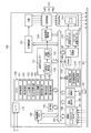
図1は、実施形態に係るプロジェクター100の全体構成を示すブロック図である。プロジェクター100は、内蔵する画像記憶部171に記憶した画像データに基づいて、スクリーンSC(投射面)に画像を投射する。また、プロジェクター100は、パーソナルコンピューターや各種映像プレーヤー等の外部の図示しない画像供給装置(図示略)から入力される画像データに基づいてスクリーンSCに画像を投射することもできる。上記画像データは動画像(映像)のデータであっても静止画像のデータであってもよい。
本実施形態では、反射幕を備えるスクリーンSCに対しプロジェクター100が前面投射する構成を例示する。スクリーンSCはほぼ直立しており、スクリーン面は矩形形状である。なお、プロジェクター100が画像を投射する投射面は建物の壁面または天井面或いは床面を利用してもよい。また、スクリーンSCが透過式の幕を備え、このスクリーンSCの背面からプロジェクター100が画像を投射してもよい。
Embodiments to which the present invention is applied will be described below with reference to the drawings.
FIG. 1 is a block diagram illustrating an overall configuration of a
In the present embodiment, a configuration in which the
プロジェクター100は、その本体に、光学的な画像の形成を行う投射部101を備える。
投射部101は、光源140、光変調装置130、投射光学系150から構成される。光源140としては、キセノンランプ、超高圧水銀ランプ、LED(Light Emitting Diode)、レーザー光源等を使用できる。なお、投射部101が、光源140が発した光を光変調装置130に導くリフレクターや、光源140が発した光を減光させる調光部(図示略)等を備えてもよい。
The
The
光変調装置130は、光源140が発した光を変調して画像光を生成する。光変調装置130には、例えば、RGBの各色に対応した3枚の透過型液晶ライトバルブを用いた方式を採用できる。この場合、光源140が発した光がダイクロイックミラー等によりR、G、Bの各色光に分離されて光変調装置130に入射する。そして、光変調装置130が備える3色の液晶パネルによって3つの色光が変調され、変調された光がクロスダイクロイックプリズムにより合成される。光変調装置130は、光変調装置駆動部134によって駆動され、マトリクス状に配置された各画素における光の透過率を変化させることにより、画像を形成する。
The
投射光学系150は、投射する画像の拡大・縮小及び焦点の調整を行うズームレンズ151、ズームの度合いを調整するズーム調整用モーター152、フォーカスの調整を行うフォーカス調整用モーター153を備える。投射光学系150は、光変調装置130で変調された光をスクリーンSC上に投射する。これによりスクリーンSCに投射画像が結像する。ズームレンズ151は、複数のレンズを含むレンズ群により構成され、ズーム調整用モーター152とフォーカス調整用モーター153がズームレンズ151のレンズ群を駆動する。この動作により、スクリーンSC上の投射画像を拡大・縮小、及び、フォーカス調整が行われる。
The projection
また、プロジェクター100の本体は、プロジェクター100全体の動作を制御して画像信号を電気的に処理する画像処理系を備える。画像処理系は、プロジェクター100全体を制御するCPU120、画像用プロセッサー131、RAM160及びROM170を備えている。CPU120は、ROM170に記憶されたプログラムを実行して、制御機能および画像処理機能を実現する。
RAM160は、CPU120や画像用プロセッサー131が実行するプログラムやデータを一時的に格納するワークエリアを形成する。なお、画像用プロセッサー131は、自身が行う画像の表示状態の調整処理など、各処理の実行の際に必要となるワークエリアを、内蔵RAMとして備えてもよい。
ROM170は、CPU120が実行するプログラム、及び、CPU120が実行するプログラムで処理されるデータを記憶する。また、ROM170は、画像記憶部171、設定値記憶部172、及び条件記憶部173を備える。
The main body of the
The
The
また、プロジェクター100の画像処理系は、光変調装置駆動部134、光源駆動部141、レンズ駆動部154、撮像部180、撮影画像メモリー182、動き検出部185、リモコン制御部190、リモコン191、操作部195を備える。CPU120、画像用プロセッサー131、及び上記の各部は、バス102により相互接続されている。
The image processing system of the
画像用プロセッサー131には、I/F(インターフェイス)110が接続される。I/F110には、上述した外部の画像供給装置(図示略)から画像データが入力される。I/F110は画像供給装置に有線接続されるコネクターや、画像供給装置との間で無線通信を行う無線通信装置を備えている。I/F110には、複数の画像供給装置を接続可能であり、複数系統の画像データが入力される。I/F110は、CPU120の制御に従って、画像データの入力系統を切り替えて、画像用プロセッサー131に画像データを出力する。本実施形態ではI/F110に入力系統IN1、IN2の2系統の画像データが入力される。
I/F110は、デジタル画像データ(デジタル映像データを含む)が入力され、このデジタル画像データを画像用プロセッサー131に出力するデジタルインターフェイスである。I/F110は、入力系統IN1、IN2から入力される画像データのフレーム変換、解像度変換、3D/2D変換等のデータ変換処理を行う機能を備えていてもよい。また、I/F110は、A/D(アナログ/デジタル)変換機能を備え、画像供給装置からアナログ映像信号を入力可能なものであってもよい。
An I / F (interface) 110 is connected to the
The I /
CPU120は、投射制御部121、補正制御部122、ズーム比算出部123、焦点距離算出部124、三次元測量部125、投射角算出部126、操作検出部127、及び撮像制御部128を備えている。これらの各部は、CPU120がROM170に記憶したプログラムを実行することにより実現される。CPU120の各部の機能は後述する。
The
画像用プロセッサー131は、台形歪み補正部132、及び重畳処理部133を備える。画像用プロセッサー131は、CPU120の制御に従って、I/F110から入力される画像データを処理し、画像信号を生成して、光変調装置駆動部134に出力する。また、プロジェクター100が画像記憶部171に記憶した画像データを投射する場合、画像用プロセッサー131はこの画像データに対し上記の処理を行う。
画像用プロセッサー131は、台形歪み補正用や画像処理用のDSP(デジタルシグナルプロセッサー)として販売されている汎用のプロセッサーを用いることができ、専用のASICを用いることもできる。
The
As the
台形歪み補正部132は、CPU120から入力される補正パラメーターをもとに、CPU120の制御に従って画像を補正する。台形歪み補正部132は、プロジェクター100がスクリーンSCに投射する投射画像の台形歪みを補正し、補正後の画像データを重畳処理部133に出力する。
重畳処理部133は、台形歪み補正部132により補正された画像データに、プロジェクター100の操作用のメニュー画面等をOSD画像として重畳する処理を実行する。重畳処理部133は、処理後の画像データを表示するための画像信号を生成し、光変調装置駆動部134に出力する。
また、画像用プロセッサー131は、台形歪み補正部132及び重畳処理部133の機能により、I/F110から入力される画像データに対して、輝度、コントラスト、色の濃さ、色合い等の画像の表示状態を調整する処理を行ってもよい。
The trapezoidal
The
Further, the
光変調装置駆動部134は、画像用プロセッサー131から入力される画像信号に基づいて、光変調装置130を駆動する。これにより、I/F110に入力された画像データに基づく画像が、光変調装置130の画像形成領域に形成される。光変調装置130に形成された画像が投射光学系150を介して、スクリーンSC上に投射画像として形成される。
The light
光源駆動部141は、CPU120から入力される指示信号に応じて、光源140に電圧を印加し、光源140を点灯及び消灯させる。
レンズ駆動部154は、CPU120の制御に従ってズーム調整用モーター152及びフォーカス調整用モーター153を駆動して、ズーム調整及びフォーカス調整を行う。
The light
The
撮像部180は、周知のイメージセンサーであるCCDを用いたCCDカメラ181と、CCDカメラ181の前方に配置されたカメラレンズ183とを備える。CCDカメラ181は、CCDの他、CCDから画像信号を読み出す制御回路等の図示しない周辺回路を備える。撮像部180は、プロジェクター100の前面、即ち、投射光学系150がスクリーンSCに向けて画像を投射する方向をCCDカメラ181により撮影可能な位置に設けられる。つまり、撮像部180は、投射光学系150の投射方向と同じ方向を撮影するよう設けられる。CCDカメラ181の撮影方向及び画角は、推奨された投射距離においてスクリーンSC上に投射された投射画像の全体が少なくとも撮像範囲内に入るように設定される。
The
CCDカメラ181が撮影した撮影画像のデータは、撮像部180から撮影画像メモリー182に出力され、撮影画像メモリー182の所定の領域に記録される。撮影画像メモリー182は、1画面分の画像データの書き込みが完了すると、所定の領域のフラグを順次反転するので、CPU120は、このフラグを参照することにより、撮像部180を用いた撮像が完了したか否かを知ることができる。CPU120は、このフラグを参照し、撮影画像メモリー182にアクセスして、必要な撮影画像データを取得する。
Data of a captured image captured by the
動き検出部185(検出部)は、ジャイロセンサーや加速度センサーを備え、プロジェクター100の本体の動きを検出して、検出値をCPU120に出力する。動き検出部185の検出値には予め閾値が設定され、CPU120は、閾値を超える動きが動き検出部185によって検出された場合に、プロジェクター100が動いたと判定する。また、CPU120は、動き検出部185によって検出される動きが閾値以下となり、この状態が予め設定された待機時間を超えて継続した場合に、プロジェクター100が静止したと判定する。
なお、動き検出部185に閾値が設定され、動き検出部185の検出値が閾値を超えた場合、及び、動き検出部185の検出値が閾値以下となって待機時間が経過した場合に、動き検出部185がCPU120に検出信号を出力する構成としてもよい。この場合、CPU120の処理負荷を軽減できる。
また、動き検出部185は、撮像部180の撮影画像の変化に基づいて動きを検出してもよい。この場合、動き検出部185は、撮影画像メモリー182から撮影画像データを取得し、取得した撮影画像データとは異なる時に撮影された撮影画像データと比較し、撮影画像データの差分が所定以上の場合に動きを検出する。この場合、撮像部180を利用して動きを検出できる。
The motion detection unit 185 (detection unit) includes a gyro sensor and an acceleration sensor, detects the motion of the main body of the
In addition, when a threshold value is set in the
Further, the
リモコン制御部190は、プロジェクター100の外部のリモコン191から送信される無線信号を受信する。リモコン191は、ユーザーによって操作される操作子(図示略)を備え、操作子に対する操作に応じた操作信号を赤外線信号等の無線信号として送信する。リモコン制御部190は、赤外線信号等を受信する受信部(図示略)を備える。リモコン制御部190は、リモコン191から送信された信号を受信し、解析して、ユーザーによる操作の内容を示す信号を生成してCPU120に出力する。
操作部195は、例えばプロジェクター100の本体に配置された操作パネルの操作子(図示略)により構成される。操作部195は、上記操作子に対する操作を検出すると、操作子に対応する操作信号をCPU120に出力する。
Remote
The
CPU120が備える投射制御部121は、I/F110が出力する画像データに基づいて、投射部101により画像を投射する動作を制御する。投射制御部121は、プロジェクター100の電源オン/オフに伴い光源駆動部141によって光源140を点灯/消灯させる制御、I/F110が出力する画像データを画像用プロセッサー131により処理させる制御等を行う。
補正制御部122は、台形歪み補正部132を制御して、台形歪みを補正する歪み補正処理を実行させる。補正制御部122は、台形歪み補正部132と協働して、補正部として機能する。
A
The
補正制御部122は、撮影画像メモリー182から撮影画像データを取得し、撮影画像データの形状を解析することにより投射画像の歪みを補正するためのパラメーターを算出する。ここで、補正制御部122は、ROM170に記憶した補正用パターン(図示略)を投射制御部121の制御によりスクリーンSCに投射させてもよい。この場合、補正制御部122は、撮像部180の撮影画像データから補正用パターンを抽出し、補正用パターンの形状を解析して、パラメーターを算出する。補正制御部122は、算出したパラメーターを台形歪み補正部132に出力し、このパラメーターに従って台形歪み補正を実行させる。
The
ズーム比算出部123は、リモコン191の操作または操作部195における操作に対応して、ズームレンズ151により投射画像を拡大または縮小するためのズーム比を算出する。投射角算出部126は、撮影画像メモリー182に記憶された撮影画像データに基づいてスクリーンSCの平面に対するズームレンズ151の光軸の傾き、すなわち投射角を算出する。また、三次元測量部125は、ズーム比算出部123が算出したズーム比および投射角算出部126が算出した投射角をもとに、撮影画像メモリー182に記憶された撮影画像データを解析して、ズームレンズ151の基準位置からスクリーンSCまでの距離(投射距離)を算出する。焦点距離算出部124は、三次元測量部125が算出した距離に基づきフォーカス調整用モーター153を駆動する駆動量を算出してレンズ駆動部154を制御し、フォーカス調整を実行させる。
補正制御部122は、ズーム比算出部123、焦点距離算出部124、三次元測量部125、及び投射角算出部126が算出した投射距離及び投射角等に基づき、補正用のパラメーターを算出する。このパラメーターは、光変調装置130により描画される画像を、スクリーンSC上の投射画像の歪みを補償するように変形させるためのパラメーターである。例えば、変形の方向、変形量等を定義するデータを含むパラメーターである。補正制御部122は、このパラメーターを、他の算出結果等とともにROM170に記憶する。
The zoom
The
操作検出部127(第2処理部)は、操作検出処理(第2の処理)を実行し、スクリーンSCにおいて指示体を用いて行われる位置指示操作を検出する。位置指示操作は、プロジェクター100の動作中に、撮像部180の画角内で指示体が位置を指し示す操作である。指示体は、撮像部180の撮影画像データに写り、プロジェクター100の投射画像を識別できるものであれば、具体的態様は限定されない。例えば、指示体はユーザーが手に持って使う棒状のデバイスであってもよいし、他の形状の器具であってもよい。このデバイスや器具は、発光する機能や無線信号を送信する機能を持っていてもよいし、この種の機能を持たないものであってもよい。また、ユーザーの身体の一部(例えば、手や指)が指示体であってもよい。また、レーザーポインター等の発光装置(図示略)がスクリーンSCに光を照射することにより、スクリーンSC上に形成される輝点が指示体であってもよい。
The operation detection unit 127 (second processing unit) executes an operation detection process (second process), and detects a position instruction operation performed using an indicator on the screen SC. The position instruction operation is an operation in which the indicator indicates the position within the angle of view of the
操作検出部127は、撮影画像メモリー182に記憶された撮影画像データに基づいて位置指示操作があったことを検出する。操作検出部127は、操作検出処理で、指示体が指示した位置を特定し、指示位置の座標を出力してもよい。また、操作検出部127は、操作検出処理で、位置指示操作により指示された操作位置を検出するだけでなく、検出された位置が予め設定された条件に該当するか否かを判定できる。さらに、操作検出部127は、検出された位置の軌跡が予め設定された条件に該当するか否かを判定できる。ここで、位置の軌跡とは、操作検出部127が時間差をおいて検出した複数回の位置指示操作の指示位置を結んで形成される図形である。操作検出部127が判定を行う条件は、ROM170の条件記憶部173に記憶される。条件記憶部173には、操作検出部127が判定する条件と、その条件に該当する操作が検出された場合に実行する処理とが対応付けて設定されている。
The
本実施形態では、指示体によってスクリーンSC上の特定の位置が指示されたことを条件とし、この条件に該当する操作を検出した場合の動作として、入力ソースの切り替えを実行する。入力ソースの切り替えとは、I/F110に接続された画像供給装置(画像ソース)を切り替える動作であり、具体的には、CPU120の制御によりI/F110が入力系統IN1と入力系統IN2を切り替える動作である。
In the present embodiment, on the condition that a specific position on the screen SC is indicated by the indicator, the input source is switched as an operation when an operation corresponding to this condition is detected. The input source switching is an operation of switching an image supply device (image source) connected to the I /
図2(A)〜(D)は、位置指示操作に対応する動作例を示す説明図である。
図2(A)に示す状態では、スクリーンSCに投射画像61が投射されている。投射画像61は、I/F110の入力系統IN1から入力される画像データに基づいて投射される画像である。つまり、図2(A)の状態ではI/F110が入力系統IN1を選択している。投射画像61は、オブジェクト62を含んでいる。
操作検出部127は、位置指示操作を検出する検出動作を開始すると、重畳処理部133を制御して、投射画像61に検出用画像63を重畳して投射させる。重畳処理部133は、予めROM170に記憶された検出用画像63の画像を台形歪み補正部132から入力される画像に重畳して、光変調装置駆動部134により描画させる。これにより検出用画像63がスクリーンSCに投射される。検出用画像63は、オブジェクト62を遮るおそれが少なく、かつ操作しやすい場所になるように、スクリーンSCの端部に配置される。図2(A)の例では検出用画像63は予め設定されたサイズの略矩形である。
2A to 2D are explanatory diagrams illustrating an operation example corresponding to the position instruction operation.
In the state shown in FIG. 2A, the
When the
操作検出部127は、撮影画像上における検出用画像63の位置およびサイズを特定する。例えば、操作検出部127は、パネル上(光変調装置130の画像形成領域)における検出用画像63の位置およびサイズを、ROM170から読み出したり、計算したりして取得する。例えば、検出用画像63を入力画像に重畳する場合の位置及びサイズを示すデータ、或いは、パネル上における検出用画像63の位置およびサイズを示すデータを、検出用画像63の画像データとともにROM170に記憶していてもよい。
そして、操作検出部127は、撮像画像における補正用パターンの位置と、三次元測量部125および投射角算出部126で算出された投写距離および投射角と、投射画像の歪みの補正量(補正用のパラメーター)のうち、少なくとも1つ以上のパラメーターに基づいて、パネル上における検出用画像63の位置およびサイズから、撮影画像上における検出用画像63の位置およびサイズを導く。或いは、撮影画像上における検出用画像63の位置は、検出用画像63の表示前後で撮影画像の差分をとって特定したり、パターンマッチングによって特定したりすることも可能である。
操作検出部127は、検出用画像63に重なる範囲を、検出領域として設定する。操作検出部127は、撮像部180の撮影画像データに基づき指示体の指示位置を特定し、指示位置が検出領域内であった場合に、特定の操作がなされたと判定する。
一例として、ユーザーの手が指示体2として使われる場合を説明する。
The
Then, the
The
As an example, a case where a user's hand is used as the
検出用画像63が投射された状態で、図2(B)に示すように指示体2が検出用画像63に重なると、操作検出部127は、撮像部180の撮影画像データに基づいて指示体2が検出用画像63に重なったと判定する。指示体2が検出用画像63に重なると、投射部101が投射した光がスクリーンSCの前で指示体2により遮られる。このため、撮像部180の撮影画像データでは、指示体2が重なった部分で検出用画像63の明るさ、色、見え方等が変化する。操作検出部127は、撮影画像データから検出用画像63の画像、すなわち検出領域の画像を抽出して解析し、明るさや色の変化を検出することで、指示体2の操作の有無を判定する。
操作検出部127は、検出用画像63の位置を、補正制御部122が投射させた補正用のパターンの位置と歪みの補正量(パラメーター)とをもとに、特定してもよい。この場合、より正確に検出用画像63の位置を特定し、操作を検出できる。さらに、操作検出部127は、撮影画像メモリー182から撮像部180の撮影画像データを取得してから、検出領域である検出用画像63及びその周辺の画像のみを抽出して、抽出した画像を解析してもよい。この場合、操作検出部127が指示体2の画像を抽出する処理、検出用画像63の画像を比較する処理等において処理するデータ量を減らすことができ、処理負荷を軽減できる。
When the
The
操作検出部127が検出用画像63への操作の有無を判定する条件は、例えば次の通りである。
操作検出部127は、検出用画像63の上(検出領域)に、予め設定された時間以上、指示体2が存在している場合に、操作ありと判定する。具体的には、撮影画像データにおける検出領域内の少なくとも一部の画素に対し、下記式(1)または(2)のいずれかが、予め設定された時間以上継続した場合に、操作ありと判定する。
画素の輝度値>第1の閾値 …(1)
画素の輝度値<第2の閾値 …(2)
The conditions for the
The
Pixel luminance value> first threshold value (1)
Pixel luminance value <second threshold value (2)
また、操作検出部127は、撮影画像データから検出用画像63の画像を抽出し、非操作時の撮影画像データにおける検出用画像63の画像と比較して、検出用画像63の画像の形状の変化を検出してもよい。この場合、検出用画像63の形状変化が所定時間成立した場合に、操作ありと判定する。
また、操作検出部127は、撮影画像データから指示体2の画像を抽出し、指示体2の画像の位置と検出用画像63の位置とを比較して、検出用画像63への操作の有無を判定してもよい。
これらの条件、及び、条件の判定に要する第1及び第2の閾値や検出用画像63の位置、サイズ、形状等に関するデータは、予め設定され、条件記憶部173に記憶される。
In addition, the
In addition, the
These conditions and the data relating to the first and second threshold values and the position, size, shape, etc. of the
また、操作検出部127は、上記の判定を行う場合に、検出用画像63の少なくとも一部が撮影画像データに表れていることを条件としてもよい。この場合、例えば撮像部180の近くや検出用画像63の近くにユーザーやユーザー以外の人が立ったことで、検出用画像63が隠されたことと、指示体2による操作とを識別できる。そして、指示体2によって意図的に検出用画像63が操作された場合に、操作を検出し、意図しない誤操作の検出を防止できる。
Further, when performing the above determination, the
図2(B)に示すように、指示体2によって検出用画像63が操作されたことを検出した場合、操作検出部127は、操作に対応付けて予め設定された動作を実行する。本実施形態では、上述のようにソース切り替えを実行し、操作検出部127がI/F110を制御して、入力系統IN1から入力系統IN2への切り替えが行われる。
これにより、図2(C)に示すように、スクリーンSCに投射される画像が、入力系統IN1の投射画像61から、入力系統IN2の投射画像65に切り替わる。投射画像65はオブジェクト66を含む画像である。
As shown in FIG. 2B, when it is detected that the
As a result, as shown in FIG. 2C, the image projected on the screen SC is switched from the
操作検出部127が操作検出処理を継続している間は、投射画像61から投射画像65への切り替え後も、図2(C)に示すように、検出用画像63が投射される。ここで、図2(D)に示すように、検出用画像63に対して指示体2による操作が行われると、この操作を操作検出部127が検出して、I/F110のソースを切り替えさせる。
While the
図2(A)〜(D)には検出用画像63をスクリーンSC上に1つだけ投射する例を示したが、検出領域の数は任意であり、例えば複数の検出領域を設定し、それぞれの検出領域を示す検出用画像を投射してもよい。この場合、それぞれの検出領域に同一の動作を対応付けてもよいし、異なる動作を対応付けてもよい。つまり、複数の検出領域のいずれかに対する操作を検出した場合に、設定された1つの動作を実行してもよく、操作を検出した検出領域に対応付けられた動作を実行してもよい。さらに、複数の操作領域の組合せに対応付けて動作を設定し、操作された操作領域の組合せに対応する動作を実行してもよい。スクリーンSCに設けられる投射領域の数、及び、投射領域に対応付けて設定される動作は、予め設定され、条件記憶部173に記憶される。
FIGS. 2A to 2D show an example in which only one
また、操作検出部127が指示体の指示位置を特定可能な場合、指示位置の軌跡に対してプロジェクター100の動作(機能)を割り当ててもよい。また、形状の異なる複数の指示体が使用され、操作検出部127が撮影画像データに基づき指示体の形状を識別可能な場合に、操作を検出した指示体の形状に対応付けて動作を割り当ててもよい。この場合、指示体により操作を行うと、操作に用いた指示体の形状に対応した動作が実行される。また、指示体がポインターにより形成されるスクリーンSC上の輝点である場合や、指示体が発光機能を有する場合に、輝点や指示体の明滅の回数、速度、点灯時間、明滅パターン等に対応付けて動作を割り当ててもよい。
Further, when the
検出領域の操作に対応して実行される動作は、ソース切り替えに限らず、例えば、スクリーンSC上の投射映像の拡大、縮小、回転、移動等の投射制御処理を割り当ててもよい。また、投射中の画像の投射を停止し音声出力も停止するミュート機能を割り当ててもよい。また、入力系統IN1と入力系統IN2のいずれか一方の画像データに基づく画像を投射するシングル表示と、複数系統の画像データに基づく複数の画像を並べてスクリーンSCに投射するマルチ表示とを切り替える動作であってもよい。さらに、プロジェクター100の電源をオフにする動作、指示体の指示位置に追従して図形を描く動作、図示しない外部記憶媒体に記憶された画像データを選択して表示する動作等を割り当ててもよい。
The operation executed in response to the operation of the detection area is not limited to source switching, and for example, projection control processing such as enlargement, reduction, rotation, and movement of the projected image on the screen SC may be assigned. Further, a mute function for stopping projection of an image being projected and stopping sound output may be assigned. Further, it is an operation for switching between a single display for projecting an image based on image data of one of the input system IN1 and the input system IN2 and a multi-display for projecting a plurality of images based on a plurality of systems of image data and projecting them on the screen SC. There may be. Further, an operation of turning off the power of the
撮像制御部128(制御部)は、撮像部180が撮影を実行する場合の撮影解像度を設定し、撮像部180を制御して撮影を実行させる。ここで、CCDカメラ181が備える受光素子の数は決まっている。このため、撮像制御部128は、CCDカメラ181が出力する撮影画像データを、特定の解像度の画像データに変換して、撮影画像メモリー182に記憶させる。この場合、撮像制御部128が撮影画像メモリー182に記憶させる撮影画像データの解像度が、撮像部180の撮影解像度に相当する。また、CCDカメラ181が備える周辺回路(図示略)の機能により、CCDカメラ181の撮像素子が出力する信号に基づき、撮像制御部128が指定した解像度の撮影画像データを生成してもよい。このような方法により、撮像制御部128は、CCDカメラ181により撮影を実行して得られる撮影画像データの解像度を、任意の解像度に調整することが可能である。本実施形態の撮像制御部128は、一例として、QVGA(320画素×240画素)とVGA(640画素×480画素)の2段階の撮影解像度を設定可能である。撮像制御部128が設定可能な解像度は、例えばROM170の設定値記憶部172に記憶されている。
The imaging control unit 128 (control unit) sets an imaging resolution when the
撮像制御部128は、補正制御部122が歪み補正処理を実行する場合、撮像部180の撮影解像度を、高画質(高解像度)のVGAに設定する。歪み補正処理では、歪み補正用のパターンやスクリーンSC上の投射画像の外形を高精度で検出できると、高精度の歪み補正を行うことができるので、好ましい。
また、撮像制御部128は、操作検出部127が操作検出処理を実行する場合、撮像部180の撮影解像度をQVGAに設定する。操作検出部127の操作検出処理では低解像度の画像であっても指示体の操作を検出可能である。また、低解像度の画像データを利用すると処理するデータ量が小さいため処理負荷が軽く、高速に処理できるので、指示体の操作を速やかに検出できるという利点がある。
When the
The
撮像制御部128は、1つの撮像部180を活用するため、補正制御部122が歪み補正処理を行う動作状態と、操作検出部127が操作検出処理を行う動作状態とを切り替える制御を実行し、動作状態に対応した撮影解像度を撮像部180に設定する。
補正制御部122の歪み補正処理は、プロジェクター100とスクリーンSCとの相対位置に合わせて実行すれば、その後は相対位置が変化しない限り実行しなくてもよい。このため、撮像制御部128は、動き検出部185によりプロジェクター100の動きを検出し、動作状態を切り替える制御を行う。この動作についてフローチャートを参照して説明する。
In order to utilize one
If the distortion correction processing of the
図3は、プロジェクター100の動作を示すフローチャートである。
CPU120は、リモコン191または操作部195の操作に従って、投射制御部121の制御により画像の投射を開始する(ステップS11)。
投射開始後、補正制御部122は、前回プロジェクター100を使用した際に用いられた補正用のパラメーターをROM170から読み出し、このパラメーターを用いて台形歪み補正を行う(ステップS12)。なお、前回のパラメーターに代えて、既定のパラメーター(初期設定値)を用いて台形歪み補正を行うようにしてもよい。
FIG. 3 is a flowchart showing the operation of the
The
After the start of projection, the
その後、動き検出部185が動き検出を開始する(ステップS13)。
撮像制御部128は、動き検出部185の出力に基づきプロジェクター100の動きの有無を判定する(ステップS14)。プロジェクター100が動いている場合、またはプロジェクター100の動きが止まってから所定時間以上経過していない場合、撮像制御部128はプロジェクター100が動いていると判定する。プロジェクター100が動いていると判定した場合(ステップS14;Yes)、撮像制御部128は、プロジェクター100の動作状態の切り替えが済んでいるか否かを判定する(ステップS15)。上記のように、プロジェクター100の動きを検出した場合は補正制御部122が歪み補正処理を行う動作状態が設定される。ステップS15で、撮像制御部128は、動作状態が既に歪み補正処理を行う動作状態に設定されているか、操作検出部127が操作検出処理を行う動作状態であるかを判定する。
Thereafter, the
The
プロジェクター100の動作状態が歪み補正処理を行う動作状態に設定されていない場合(ステップS15;No)、撮像制御部128は歪み補正処理を実行する動作状態に切り替える。すなわち、検出用画像の投射を停止させ(ステップS16)、撮像部180の撮影解像度をVGAに設定し(ステップS17)、ステップS18に移行する。
また、プロジェクター100の動作状態が歪み補正処理を行う動作状態に設定されている場合(ステップS15;Yes)、撮像制御部128はステップS18に移行する。
When the operation state of the
If the operation state of the
ステップS18で、撮像制御部128は撮像部180による撮影を実行させる。続いて、補正制御部122は、撮像部180の撮影画像データに基づいて歪み補正用のパラメーターを新たに算出して、台形歪み補正部132が使用するパラメーターを更新する(ステップS19)。この更新されたパラメーターを用いて、台形歪み補正部132が台形歪み補正処理を実行する(ステップS20)。
撮像制御部128は、操作部195またはリモコン191によりプロジェクター100の動作終了が指示されたか否かを判定する(ステップS21)。終了の指示がなされた場合(ステップS21;Yes)、CPU120は投射を停止して本処理を終了する(ステップS22)。また、終了の指示がなされていない場合(ステップS21;No)、ステップS14に戻って動きを検出する。
In step S18, the
The
一方、プロジェクター100が動いていないと判定した場合(ステップS14;No)、撮像制御部128は、プロジェクター100の動作状態の切り替えが済んでいるか否かを判定する(ステップS23)。プロジェクター100の静止を検出した場合は操作検出部127が操作検出処理を行う動作状態が設定される。ここのステップS23で、撮像制御部128は、動作状態が既に操作検出処理を行う動作状態に設定されているか、歪み補正処理を行う動作状態であるかを判定する。
On the other hand, when it is determined that the
プロジェクター100の動作状態が操作検出処理を行う動作状態に設定されていない場合(ステップS23;No)、撮像制御部128は操作検出処理を実行する動作状態に切り替える。すなわち、撮像制御部128が撮像部180の撮影解像度をQVGAに設定し(ステップS24)、操作検出部127が、図2(A)〜(D)に示したように検出用画像をスクリーンSCに投射させる制御を行い(ステップS25)、ステップS26に移行する。
また、プロジェクター100の動作状態が操作検出処理を行う動作状態に設定されている場合(ステップ23;Yes)、撮像制御部128はステップS26に移行する。
When the operation state of the
When the operation state of the
ステップS26では、操作検出部127が撮像部180に撮影を実行させ、撮影画像データを解析して操作を検出する(ステップS27)。
ここで、操作検出部127は、予め設定された条件に該当する操作が行われたか否かを判定する(ステップS28)。条件に該当する操作が行われたと判定した場合(ステップS28;Yes)、操作検出部127は、条件に対応付けて設定された動作を実行する(ステップS29)。例えば、上述したソース切り替えを実行し、ステップS30に移行する。
また、操作検出部127は、予め設定された条件に該当する操作が行われなかったと判定した場合(ステップS28;No)、操作検出部127は、そのままステップS30に移行する。
In step S26, the
Here, the
If the
ステップS30で、撮像制御部128は、操作部195またはリモコン191によりプロジェクター100の動作終了が指示されたか否かを判定する。終了の指示がなされた場合(ステップS30;Yes)、CPU120はステップS22に移行して投射を停止し、本処理を終了する。また、終了の指示がなされていない場合(ステップS30;No)、ステップS14に戻る。
In step S <b> 30, the
なお、撮像制御部128の動作は図3に示したフロー制御に限定されない。撮像制御部128は、ステップS12でプロジェクター100の動きの判定を開始し、プロジェクター100の動きが止まったと判定した時点で、割り込み制御により、ステップS16、S24相当の判定を行ってもよい。この場合、撮像制御部128は、プロジェクター100が動いた場合、及び動きが止まった場合に、速やかに動作状態を切り替えることができる。また、リモコン191または操作部195によって投射終了が指示される場合も同様であり、図3に示したフロー制御に限定されず、操作を検出してステップS27と同様の処理を割り込み制御により行ってもよい。
The operation of the
以上説明したように、プロジェクター100は、画像を投射する投射部101を有する本体と、本体の動きを検出する動き検出部185と、スクリーンSCを撮像する撮像部180とを備える。また、撮像部180の撮像結果に基づいて台形歪み補正を行う補正制御部122と、撮像部180の撮像結果に基づいて台形歪み補正とは異なる第2の処理を実行する第2処理部とを備える。撮像制御部128は、動き検出部185の検出結果に基づいて、本体が動いていると判定した場合には補正制御部122による台形歪み補正を行わせ、動き検出部185が停止したと判定した場合に操作検出部127に操作検出処理を実行させる。このため、台形歪み補正を必要な場合に実行し、台形歪み補正と、操作検出処理とで撮像部180の撮影画像データを使い分けて、撮像部180を効果的に利用できる。
また、操作検出部127は、撮像部180の撮像結果に基づいてスクリーンSCに対する指示体の操作を検出し、検出した操作が予め設定された条件に該当する場合に、該当する条件に対応付けられた処理を実行する。このため、撮像部180の撮像結果を利用して、条件に該当する操作が行われた場合に予め設定された処理を実行できる。また、操作検出部127は、スクリーンSCに設定した操作領域に対する指示体の操作を検出できる。
As described above, the
The
なお、上述した実施形態は本発明を適用した具体的態様の例に過ぎず、本発明を限定するものではなく、上記実施形態とは異なる態様として本発明を適用することも可能である。例えば、上記実施形態では、I/F110に入力される複数系統の入力系統IN1、IN2を切り替えて、入力画像データに基づく画像を投射する場合を例に挙げて説明した。つまり、操作検出部127が検出した操作に対応して、I/F110が入力系統IN1と入力系統IN2とを切り替える例を説明した。本発明はこれに限定されるものではなく、I/F110に入力される画像データと、ROM170に記憶された画像データとを切り替えて投射する構成としてもよいし、プロジェクター100に接続された外部記憶装置が記憶する画像データを利用してもよい。
また、予め設定された処理は、I/F110の入力系統IN1,IN2を切り替えるソース切り替え処理に限定されない。例えば、予め設定された処理として、上述したミュート機能を実行し、プロジェクター100の画像、または画像と音声の出力を一時的に停止する処理、または再開する処理を行ってもよい。或いは、光変調装置130が描画する画像を拡大または縮小する電子ズーム処理や、プロジェクター100が出力する音声の音量制御処理等を行ってもよい。
さらに、上記実施形態では、一例として、操作検出部127が撮影画像データにおける検出用画像63の明るさが変化した場合に、指示体2による操作ありと判定し、ソース切り替えを実行する構成を説明した。つまり、検出用画像63に指示体2を重ねたときにソース切り替えが実行される例であった。本発明はこれに限定されず、撮影画像データにおける検出用画像63の明るさが変化して、それが元に戻ったときに、操作検出部127が指示体2による操作があったと判定してもよい。つまり、スクリーンSC上の検出用画像63に重ねられた指示体2が検出用画像63から離れたときに、予め設定された処理が実行される構成としてもよい。
また、上記実施形態ではプロジェクター100の各部の動作を規定する時間や閾値等に関する設定値は、ROM170に予め記憶されているが、本発明はこれに限定されない。上記の設定値を、プロジェクター100の外部の記憶媒体や記憶装置に記憶しておき、必要に応じてプロジェクター100により設定値が取得される構成としてもよい。また、リモコン191や操作部195の操作によってその都度設定値が入力される構成としてもよい。
The above-described embodiment is merely an example of a specific mode to which the present invention is applied, and the present invention is not limited. The present invention can be applied as a mode different from the above-described embodiment. For example, in the above-described embodiment, a case where an image based on input image data is projected by switching a plurality of input systems IN1 and IN2 input to the I /
Further, the preset process is not limited to the source switching process for switching the input systems IN1 and IN2 of the I /
Furthermore, in the above embodiment, as an example, a configuration is described in which the
In the above embodiment, the setting values relating to the time, threshold value, and the like that define the operation of each unit of the
また、上記実施形態では、プロジェクター100の本体に投射部101と撮像部180とが固定された構成として説明したが、投射部101と撮像部180とを、プロジェクター100の本体とは別体として構成することも可能である。また、上記実施形態では、補正制御部122が投射画像の台形歪みを補正する場合を説明したが、例えば、いわゆる樽型歪みや糸巻き歪みと呼ばれる歪みを補正する処理を行ってもよい。
また、上記実施形態では、撮像部180はCCDイメージセンサーを備えたCCDカメラ181を有する構成として説明したが、イメージセンサーとしてCMOSセンサーを用いても良い。また、上記実施形態では、光変調装置として、RGBの各色に対応した3枚の透過型の液晶パネルを用いた構成を例に挙げて説明したが、反射型の液晶パネルを用いてもよい。また、例えば、1枚の液晶パネルとカラーホイールを組み合わせた方式、RGB各色の色光を変調する3枚のデジタルミラーデバイス(DMD)を用いた方式、1枚のデジタルミラーデバイスとカラーホイールを組み合わせた方式等により構成してもよい。
また、図1に示した各機能部は、プロジェクター100の機能的構成を示すものであって、具体的な実装形態は特に制限されない。つまり、必ずしも各機能部に個別に対応するハードウェアが実装される必要はなく、一つのプロセッサーがプログラムを実行することで複数の機能部の機能を実現する構成とすることも勿論可能である。また、上記実施形態においてソフトウェアで実現されている機能の一部をハードウェアで実現してもよく、あるいは、ハードウェアで実現されている機能の一部をソフトウェアで実現してもよい。
In the above embodiment, the
In the above embodiment, the
Further, each functional unit illustrated in FIG. 1 indicates a functional configuration of the
100…プロジェクター、101…投射部、120…CPU、121…投射制御部、122…補正制御部(補正部)、127…操作検出部(第2処理部)、128…撮像制御部(制御部)、130…光変調装置、131…画像用プロセッサー、132…台形歪み補正部(補正部)、134…光変調装置駆動部、150…投射光学系、180…撮像部、183…カメラレンズ、185…動き検出部(検出部)、SC…スクリーン(投射面)。
DESCRIPTION OF
Claims (5)
前記本体の動きを検出する検出部と、
投射面を撮像する撮像部と、
前記撮像部の撮像結果に基づいて台形歪み補正を行う補正部と、
前記撮像部の撮像結果に基づいて前記台形歪み補正とは異なる第2の処理を実行する第2処理部と、
前記検出部の検出結果に基づいて、前記本体が動いていると判定した場合には前記補正部による前記台形歪み補正を行わせ、前記本体が停止したと判定した場合に前記第2処理部により前記第2の処理を実行させる制御部と、を備え、
前記制御部は、前記本体が停止したと判定した場合に、前記投射部により予め設定されたサイズの検出用画像を前記投射面に投射させて前記第2処理部に前記第2の処理を実行させ、前記本体が動いていると判定した場合に、前記投射部に前記検出用画像の投射を停止させて前記補正部による前記台形歪み補正を行わせ、
前記第2の処理を実行する前記第2処理部は、前記撮像部の撮像結果に基づいて、前記投射面に投射された前記検出用画像に重なるように行われる操作を検出する操作検出部であり、
前記制御部は、前記補正部による前記台形歪み補正を実行させる場合に前記撮像部に設定する撮像解像度を、前記第2処理部に前記第2の処理を実行させる場合に前記撮像部に設定する撮像解像度より高い解像度に設定することを特徴とするプロジェクター。 A main body having a projection unit for projecting a projection image ;
A detection unit for detecting the movement of the main body;
An imaging unit for imaging the projection surface;
A correction unit that performs trapezoidal distortion correction based on the imaging result of the imaging unit;
A second processing unit that executes a second process different from the trapezoidal distortion correction based on the imaging result of the imaging unit;
Based on the detection result of the detecting unit, wherein when it is determined that the body is moving to perform the trapezoidal distortion correction by the correction unit, by the second processing unit when the main body is determined to have stopped A controller that executes the second process ,
When the control unit determines that the main body has stopped, the control unit causes the second processing unit to execute the second process by projecting a detection image having a size set in advance by the projection unit onto the projection surface. When it is determined that the main body is moving, the projection unit stops the projection of the detection image, and the correction unit performs the trapezoidal distortion correction,
The second processing unit that executes the second process is an operation detection unit that detects an operation performed so as to overlap the detection image projected on the projection surface based on an imaging result of the imaging unit. Yes,
The control unit sets an imaging resolution set in the imaging unit when the correction unit performs the trapezoidal distortion correction, and sets the imaging resolution when the second processing unit executes the second process. A projector characterized in that the resolution is set higher than the imaging resolution .
前記制御部は、前記操作検出部により前記操作が検出されると、前記インターフェース部を制御して、前記投射部に投射させる画像データの供給元となる画像供給装置を切り替えることを特徴とする請求項1記載のプロジェクター。 It has an interface unit that can be connected to multiple image supply devices,
The said control part controls the said interface part, if the said operation detection is detected by the said operation detection part, The image supply apparatus used as the supply source of the image data projected on the said projection part is switched, It is characterized by the above-mentioned. Item 1. The projector according to Item 1.
前記検出部の検出結果に基づいて、前記本体が動いていると判定した場合に、前記補正部により前記台形歪み補正を行う第1ステップと、
前記検出部の検出結果に基づいて、前記本体が停止したと判定した場合に、前記投射部により予め設定されたサイズの検出用画像を前記投射面に投射させて、前記第2処理部により前記第2の処理を実行させる第2ステップと、を有し、
前記第1ステップにおいて、前記台形歪み補正は、前記検出用画像の投射を停止させた後に行われ、
前記第2ステップにおいて、前記第2の処理は、前記撮像部の撮像結果に基づいて、前記投射面に投射された前記検出用画像に重なるように行われる操作を検出する処理であり、
前記台形歪み補正を実行する場合に前記撮像部に設定される撮像解像度は、前記第2の処理を実行する場合に前記撮像部に設定される撮像解像度より高い解像度に設定されることを特徴とするプロジェクターの制御方法。 A main body having a projection unit that projects a projection image , a detection unit that detects movement of the main body, an imaging unit that images a projection surface, a correction unit that performs trapezoidal distortion correction based on an imaging result of the imaging unit, A second processing unit that executes a second process different from the trapezoidal distortion correction based on an imaging result of the imaging unit,
A first step of performing the trapezoidal distortion correction by the correction unit when it is determined that the main body is moving based on a detection result of the detection unit;
Based on the detection result of the detection unit, when it is determined that the main body has stopped, a detection image having a size set in advance by the projection unit is projected onto the projection surface, and the second processing unit A second step of executing a second process,
In the first step, the trapezoidal distortion correction is performed after stopping the projection of the detection image,
In the second step, the second process is a process of detecting an operation performed so as to overlap the detection image projected on the projection surface based on an imaging result of the imaging unit.
The imaging resolution set in the imaging unit when executing the trapezoidal distortion correction is set to a higher resolution than the imaging resolution set in the imaging unit when executing the second process. Projector control method.
Priority Applications (3)
| Application Number | Priority Date | Filing Date | Title |
|---|---|---|---|
| JP2013239536A JP6343910B2 (en) | 2013-11-20 | 2013-11-20 | Projector and projector control method |
| US14/537,326 US9794536B2 (en) | 2013-11-20 | 2014-11-10 | Projector, and method of controlling projector |
| CN201410669952.2A CN104660946B (en) | 2013-11-20 | 2014-11-20 | Projector and its control method |
Applications Claiming Priority (1)
| Application Number | Priority Date | Filing Date | Title |
|---|---|---|---|
| JP2013239536A JP6343910B2 (en) | 2013-11-20 | 2013-11-20 | Projector and projector control method |
Publications (3)
| Publication Number | Publication Date |
|---|---|
| JP2015099293A JP2015099293A (en) | 2015-05-28 |
| JP2015099293A5 JP2015099293A5 (en) | 2016-12-22 |
| JP6343910B2 true JP6343910B2 (en) | 2018-06-20 |
Family
ID=53172979
Family Applications (1)
| Application Number | Title | Priority Date | Filing Date |
|---|---|---|---|
| JP2013239536A Expired - Fee Related JP6343910B2 (en) | 2013-11-20 | 2013-11-20 | Projector and projector control method |
Country Status (3)
| Country | Link |
|---|---|
| US (1) | US9794536B2 (en) |
| JP (1) | JP6343910B2 (en) |
| CN (1) | CN104660946B (en) |
Cited By (1)
| Publication number | Priority date | Publication date | Assignee | Title |
|---|---|---|---|---|
| US10007029B2 (en) | 2013-10-21 | 2018-06-26 | National University Corporation Nagoya University | β-phellandrene polymer, production method for same, and molded article |
Families Citing this family (10)
| Publication number | Priority date | Publication date | Assignee | Title |
|---|---|---|---|---|
| JP6566737B2 (en) * | 2015-06-18 | 2019-08-28 | キヤノン株式会社 | Information processing apparatus, information processing method, and program |
| JP6701724B2 (en) * | 2015-12-25 | 2020-05-27 | セイコーエプソン株式会社 | Display device, projector, and communication device |
| JP6707945B2 (en) * | 2016-03-28 | 2020-06-10 | セイコーエプソン株式会社 | Display device and display device control method |
| US20170374331A1 (en) * | 2016-06-27 | 2017-12-28 | Intel Corporation | Auto keystone correction and auto focus adjustment |
| JP6897191B2 (en) * | 2017-03-17 | 2021-06-30 | セイコーエプソン株式会社 | Projector and projector control method |
| CN106950782B (en) * | 2017-05-12 | 2019-01-22 | 高树坤 | It is a kind of for determining the method and device of screen prjection automatic Proofreading |
| JP6924273B2 (en) * | 2017-11-20 | 2021-08-25 | シャープ株式会社 | Light source device and projection device |
| JP7404891B2 (en) * | 2020-01-28 | 2023-12-26 | セイコーエプソン株式会社 | Projector control method and projector |
| EP4265461A1 (en) * | 2020-12-16 | 2023-10-25 | Sony Group Corporation | Display dimming control apparatus, display dimming control method, recording medium, and display dimming system |
| JP2022179913A (en) * | 2021-05-24 | 2022-12-06 | セイコーエプソン株式会社 | projector |
Family Cites Families (14)
| Publication number | Priority date | Publication date | Assignee | Title |
|---|---|---|---|---|
| JP2005141151A (en) * | 2003-11-10 | 2005-06-02 | Seiko Epson Corp | Projector and method for setting projector function |
| JP4829855B2 (en) | 2007-09-04 | 2011-12-07 | キヤノン株式会社 | Image projection apparatus and control method thereof |
| US9241143B2 (en) * | 2008-01-29 | 2016-01-19 | At&T Intellectual Property I, L.P. | Output correction for visual projection devices |
| JP5481833B2 (en) * | 2008-10-29 | 2014-04-23 | セイコーエプソン株式会社 | Projector and projector control method |
| US8297757B2 (en) * | 2008-10-29 | 2012-10-30 | Seiko Epson Corporation | Projector and projector control method |
| JP5493340B2 (en) | 2008-11-26 | 2014-05-14 | セイコーエプソン株式会社 | Projection display apparatus and arrangement relation detection method |
| US8727539B2 (en) * | 2010-10-28 | 2014-05-20 | Seiko Epson Corporation | Projector and method of controlling projector |
| JP5197777B2 (en) * | 2011-02-01 | 2013-05-15 | 株式会社東芝 | Interface device, method, and program |
| US20140218300A1 (en) * | 2011-03-04 | 2014-08-07 | Nikon Corporation | Projection device |
| JP2012189675A (en) * | 2011-03-09 | 2012-10-04 | Seiko Epson Corp | Display device, and method for detecting movement of the same |
| JP2012255988A (en) * | 2011-06-10 | 2012-12-27 | Panasonic Corp | Image projection device and portable information processor including the same |
| JP2012256000A (en) * | 2011-06-10 | 2012-12-27 | Sanyo Electric Co Ltd | Projection video display device |
| US8830302B2 (en) * | 2011-08-24 | 2014-09-09 | Lg Electronics Inc. | Gesture-based user interface method and apparatus |
| JP6040564B2 (en) * | 2012-05-08 | 2016-12-07 | ソニー株式会社 | Image processing apparatus, projection control method, and program |
-
2013
- 2013-11-20 JP JP2013239536A patent/JP6343910B2/en not_active Expired - Fee Related
-
2014
- 2014-11-10 US US14/537,326 patent/US9794536B2/en active Active
- 2014-11-20 CN CN201410669952.2A patent/CN104660946B/en active Active
Cited By (1)
| Publication number | Priority date | Publication date | Assignee | Title |
|---|---|---|---|---|
| US10007029B2 (en) | 2013-10-21 | 2018-06-26 | National University Corporation Nagoya University | β-phellandrene polymer, production method for same, and molded article |
Also Published As
| Publication number | Publication date |
|---|---|
| CN104660946A (en) | 2015-05-27 |
| US9794536B2 (en) | 2017-10-17 |
| CN104660946B (en) | 2019-06-21 |
| US20150138513A1 (en) | 2015-05-21 |
| JP2015099293A (en) | 2015-05-28 |
Similar Documents
| Publication | Publication Date | Title |
|---|---|---|
| JP6343910B2 (en) | Projector and projector control method | |
| TWI566602B (en) | Projector and control method for the projector | |
| JP6330292B2 (en) | Projector and projector control method | |
| EP2823639B1 (en) | Projector and control method for the projector | |
| US8727539B2 (en) | Projector and method of controlling projector | |
| JP5796286B2 (en) | Projector and projector control method | |
| JP6307852B2 (en) | Image display device and method for controlling image display device | |
| KR101725512B1 (en) | Projector and method of controlling projector | |
| JP2012181721A (en) | Position input device, projector, control method for projector, and display system | |
| JP6347126B2 (en) | Projector and projector control method | |
| JP2018142856A (en) | Projector, and method for controlling projector | |
| JP5845566B2 (en) | Projector and projector control method | |
| JP5845565B2 (en) | Projector and projector control method | |
| JP5887777B2 (en) | Projector and projector control method | |
| JP6119902B2 (en) | Projector and projector control method |
Legal Events
| Date | Code | Title | Description |
|---|---|---|---|
| A521 | Written amendment |
Free format text: JAPANESE INTERMEDIATE CODE: A523 Effective date: 20161104 |
|
| A621 | Written request for application examination |
Free format text: JAPANESE INTERMEDIATE CODE: A621 Effective date: 20161104 |
|
| A977 | Report on retrieval |
Free format text: JAPANESE INTERMEDIATE CODE: A971007 Effective date: 20170829 |
|
| A131 | Notification of reasons for refusal |
Free format text: JAPANESE INTERMEDIATE CODE: A131 Effective date: 20170905 |
|
| A521 | Written amendment |
Free format text: JAPANESE INTERMEDIATE CODE: A523 Effective date: 20171106 |
|
| TRDD | Decision of grant or rejection written | ||
| A01 | Written decision to grant a patent or to grant a registration (utility model) |
Free format text: JAPANESE INTERMEDIATE CODE: A01 Effective date: 20180424 |
|
| A61 | First payment of annual fees (during grant procedure) |
Free format text: JAPANESE INTERMEDIATE CODE: A61 Effective date: 20180507 |
|
| R150 | Certificate of patent or registration of utility model |
Ref document number: 6343910 Country of ref document: JP Free format text: JAPANESE INTERMEDIATE CODE: R150 |
|
| LAPS | Cancellation because of no payment of annual fees |