JP6334895B2 - Signal processing apparatus, control method therefor, and program - Google Patents
Signal processing apparatus, control method therefor, and program Download PDFInfo
- Publication number
- JP6334895B2 JP6334895B2 JP2013237350A JP2013237350A JP6334895B2 JP 6334895 B2 JP6334895 B2 JP 6334895B2 JP 2013237350 A JP2013237350 A JP 2013237350A JP 2013237350 A JP2013237350 A JP 2013237350A JP 6334895 B2 JP6334895 B2 JP 6334895B2
- Authority
- JP
- Japan
- Prior art keywords
- signal
- sound
- noise
- output
- target sound
- Prior art date
- Legal status (The legal status is an assumption and is not a legal conclusion. Google has not performed a legal analysis and makes no representation as to the accuracy of the status listed.)
- Active
Links
Images


Classifications
-
- H—ELECTRICITY
- H04—ELECTRIC COMMUNICATION TECHNIQUE
- H04R—LOUDSPEAKERS, MICROPHONES, GRAMOPHONE PICK-UPS OR LIKE ACOUSTIC ELECTROMECHANICAL TRANSDUCERS; DEAF-AID SETS; PUBLIC ADDRESS SYSTEMS
- H04R3/00—Circuits for transducers, loudspeakers or microphones
- H04R3/04—Circuits for transducers, loudspeakers or microphones for correcting frequency response
-
- H—ELECTRICITY
- H04—ELECTRIC COMMUNICATION TECHNIQUE
- H04R—LOUDSPEAKERS, MICROPHONES, GRAMOPHONE PICK-UPS OR LIKE ACOUSTIC ELECTROMECHANICAL TRANSDUCERS; DEAF-AID SETS; PUBLIC ADDRESS SYSTEMS
- H04R3/00—Circuits for transducers, loudspeakers or microphones
- H04R3/005—Circuits for transducers, loudspeakers or microphones for combining the signals of two or more microphones
Description
本発明は、風雑音を抑制しつつ周囲の音を収録する収音技術に関する。 The present invention relates to a sound collection technique for recording ambient sounds while suppressing wind noise.
近年、カムコーダやカメラ、スマートフォン等の撮像装置の普及により気軽に画像が撮影できるようになってきている。また、高音質録音が可能なポータブルオーディオレコーダも多く普及しており、画像が付随する・しないに関わらず、屋外で周囲、もしくは目的物の音を録音する機会が増えている。 In recent years, it has become possible to easily take images with the spread of imaging devices such as camcorders, cameras, and smartphones. In addition, many portable audio recorders capable of high-quality sound recording have become widespread, and regardless of whether images are attached or not, opportunities to record sounds of surroundings or objects outdoors are increasing.
このような屋外で収音する場合において、風が収音用マイクロフォンに作用することによって生じる雑音(以下、風雑音と呼称)が収音信号に混じると、目的音が聞き取りにくくなり、また、不快な音になる。そこで、風雑音を除去、または抑制することが、従来から重要な課題になっている。 When collecting sound outdoors like this, if noise (hereinafter referred to as wind noise) generated by the wind acting on the microphone for sound collection is mixed with the collected sound signal, the target sound becomes difficult to hear and uncomfortable. Sound. Therefore, removing or suppressing wind noise has been an important issue in the past.
風雑音の周波数特性を分析すると、そのエネルギーの多くは500Hz以下の低周波数域に偏るという特徴を持っている。そこで、風雑音を抑制する従来技術の一つとして、高周波数域通過フィルタ(以下、ハイパスフィルタと呼称)を用いて風雑音を抑制する手法がある。 When the frequency characteristics of wind noise are analyzed, most of the energy is characterized by being biased to a low frequency range of 500 Hz or less. Therefore, as one of the conventional techniques for suppressing wind noise, there is a technique for suppressing wind noise by using a high frequency band pass filter (hereinafter referred to as a high pass filter).
ところが、ハイパスフィルタを用いた風雑音抑制手法では、風雑音のレベルが大きい場合、ハイパスフィルタもそれに応じて抑制量を大きくする必要がある。そのため、目的音成分の低周波数域が丸ごと抑制され、目的音の音色が変化してしまうという問題がある。 However, in the wind noise suppression method using the high-pass filter, when the wind noise level is large, the high-pass filter needs to increase the suppression amount accordingly. Therefore, there is a problem that the entire low frequency range of the target sound component is suppressed and the timbre of the target sound changes.
また、風雑音を抑制する従来技術の一つとして、風雑音信号を推定して、収音信号からスペクトル減算を行うことにより抑制する技術がある。 Further, as one of the conventional techniques for suppressing wind noise, there is a technique for estimating a wind noise signal and performing spectral subtraction from the collected sound signal.
しかしながら、スペクトル減算を用いた抑制方法においても、風雑音のレベルが大きくなりすぎると目的音成分自体がかき消されてしまい、風雑音を減算すると目的音成分までなくなってしまうという問題がある。 However, even in the suppression method using spectral subtraction, there is a problem that the target sound component itself is erased if the wind noise level becomes too high, and the target sound component is lost when the wind noise is subtracted.
そこで、風雑音抑制処理によって失われる目的音成分を、風雑音抑制後に復元してその目的音成分を補完するという従来技術が存在する。 Therefore, there is a conventional technique in which the target sound component lost by the wind noise suppression processing is restored after the wind noise suppression and the target sound component is complemented.
例えば、特許文献1では、入力信号を低・中・高の三帯域に分離し、中帯域から低帯域の復元信号を生成し、風雑音の影響度合いを推定して入力信号の低帯域信号と混合している。また、中帯域の信号レベルを低減して混合している。このような構成により、歪の発生を抑制しつつ風雑音を低減するという技術が開示されている。
For example, in
しかしながら、特許文献1の技術では、調波性のある中帯域、高帯域信号を利用して基本波や低次高調波を復元するものであり、調波性のある信号しか復元できないという課題がある。また、基本波を特定する情報は持っておらず、低次高調波のレベルバランスも考慮しないため、不正確な低帯域成分を付加してしまい、かえって音質が劣化する、あるいは、音色が変化してしまう恐れがあった。
However, the technique disclosed in
本発明は上記の課題を解決するためになされたものであり、雑音を抑制しつつ、音色変化や目的音成分の欠落を防止して、精密な目的音の復元を行うことができる収音技術を提供することを目的とする。 The present invention has been made to solve the above-described problems, and is a sound collection technique capable of accurately restoring a target sound while suppressing noise and preventing a timbre change and a loss of a target sound component. The purpose is to provide.
上記の目的を達成するための本発明による信号処理装置は以下の構成を備える。即ち、信号処理装置は、
収音手段により収音される収音信号を取得する取得手段と、
前記取得手段により取得される第1収音信号に含まれる雑音を抑制する抑制手段と、
前記取得手段により前記第1収音信号よりも前に取得された第2収音信号を用いた学習の結果に基づいて、前記第1収音信号に対応する目的音信号を生成する生成手段と、
前記生成手段により生成される前記第1収音信号に対応する目的音信号を出力する第1の出力形態と、前記抑制手段により前記第1収音信号から雑音が抑制された雑音抑制後信号を出力する第2の出力形態とを含む複数の出力形態から、適用すべき出力形態を決定する決定手段と、
前記決定手段により決定される出力形態に応じた信号を出力する出力手段と、
を備える。
In order to achieve the above object, a signal processing apparatus according to the present invention comprises the following arrangement. That is, the signal processing device
Obtaining means for obtaining a collected sound signal collected by the sound collecting means;
Suppression means for suppressing noise included in the first collected sound signal acquired by the acquisition means;
Generating means for generating a target sound signal corresponding to the first sound pickup signal based on a learning result using the second sound pickup signal acquired by the acquisition means before the first sound pickup signal; ,
A first output form for outputting a target sound signal corresponding to the first collected sound signal generated by the generating means; and a noise-suppressed signal in which noise is suppressed from the first collected sound signal by the suppressing means. Determining means for determining an output form to be applied from a plurality of output forms including a second output form to be output;
Output means for outputting a signal according to the output form determined by the determining means;
Is provided.
本発明によれば、雑音を抑制しつつ、音色変化や目的音成分の欠落を防止して、精密な目的音の復元を行うことができる。 According to the present invention, it is possible to accurately restore the target sound while suppressing noise and preventing timbre changes and missing target sound components.
以下、本発明の実施の形態について図面を用いて詳細に説明する。尚、以下の実施形態において示す構成は一例に過ぎず、本発明は図示された構成に限定されるものではない。 <実施形態1>
図1は、実施形態1の収音装置の構成を示すブロック図である。
Hereinafter, embodiments of the present invention will be described in detail with reference to the drawings. The configurations shown in the following embodiments are merely examples, and the present invention is not limited to the illustrated configurations. <
FIG. 1 is a block diagram illustrating a configuration of the sound collection device according to the first embodiment.
図1において、1は音入力部としてのマイクロフォンユニットであり、目的音を含む周囲の音を収音し、電気信号に変換する。2はマイクロフォンアンプであり、マイクロフォンユニット1が出力する微弱なアナログ音響信号を増幅して出力する。3はアナログデジタル変換器(ADC)であり、入力されたアナログ音響信号をデジタル音響信号に変換し、収音信号として出力する。
In FIG. 1,
101は雑音推定器であり、入力された収音信号に含まれる非定常雑音を推定して、推定雑音信号を出力する。102は無雑音状態推定器であり、雑音推定器101が出力する推定雑音信号が無雑音状態(雑音が弱い、もしくは、雑音が発生していない状態)であるか否かを検出し、無雑音状態である場合にのみスイッチON信号をスイッチ108に出力する。尚、無雑音状態をより定量的に表現すれば、無雑音状態とは、雑音の強度を示す雑音レベルが、雑音として知覚されない所定レベル以下である状態を意味する。
103は目的音学習器であり、入力されたデジタル音響信号を目的音信号として解析し、そのスペクトル包絡や調波構造等の特性を学習し、これらの特性を複数のパターンに類型化して、目的音モデル104に出力する。
103 is a target sound learning device, which analyzes the input digital acoustic signal as a target sound signal, learns its characteristics such as its spectral envelope and harmonic structure, etc., classifies these characteristics into a plurality of patterns, Output to the
104は目的音モデルであり、目的音学習器103が出力した目的音信号のパターン情報を格納し、目的音復元器106に適宜供給する。105は雑音抑制器であり、雑音推定器101が出力する推定雑音信号に従って、収音信号から推定雑音を抑制した信号(雑音抑制後信号)を出力する。106は目的音復元器であり、収音信号と目的音モデル104に格納されているパターン情報とのパターンマッチングを行うことにより、目的音信号を復元し、目的音復元信号として出力する。また、この時の目的音パターンの活性度を出力する。
A
107は信号選択・混合器であり、雑音抑制器105から出力される雑音抑制後信号と、目的音復元器106が出力する目的音復元信号とを、学習モデルである目的音モデルの活性度に従って、適宜置換、もしくは混合を行って出力する。
尚、収音装置は、上記の構成以外に、汎用コンピュータに搭載される標準的な構成要素(例えば、CPU、RAM、ROM、ハードディスク、外部記憶装置、ネットワークインタフェース、ディスプレイ、キーボード、マウス等)を有することができる。そして、例えば、ハードディスク等に記憶されているプログラムをCPUが読み出し実行することによって、以下で説明する各種フローチャートの処理を実行することもできる。 In addition to the above configuration, the sound collection device includes standard components (for example, a CPU, a RAM, a ROM, a hard disk, an external storage device, a network interface, a display, a keyboard, and a mouse) mounted on a general-purpose computer. Can have. Then, for example, when the CPU reads and executes a program stored in a hard disk or the like, various flowchart processes described below can be executed.
以下、図1の構成において、目的音の成分欠落や音質劣化を防止しつつ、収音信号に含まれる非定常雑音を抑制する一連の動作をフローに従って説明する。 In the following, a series of operations for suppressing non-stationary noise included in a collected sound signal while preventing missing components and sound quality deterioration of the target sound in the configuration of FIG. 1 will be described according to a flow.
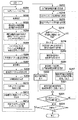
図2は、実施形態1の収音装置が実行する収音処理を示すフローチャートである。 FIG. 2 is a flowchart illustrating sound collection processing executed by the sound collection device according to the first embodiment.
まず、ステップS1で、マイクロフォンユニット1によって目的音を含む周囲の音を電気信号に変換し、マイクロフォンアンプ2によって増幅し、ADC3において、デジタル信号に変換し、所定サンプル長の処理単位フレームに切り出して出力する。
First, in step S1, ambient sound including the target sound is converted into an electric signal by the
ステップS2で、雑音推定器101において、ステップS1で切り出した収音信号の処理フレームに含まれる雑音信号を推定する。実施形態1において、モノラル音響信号から非定常雑音を推定する方法としては、線形予測を用いて予測できなかった成分を非定常雑音とする方法や、予め学習した音源(音声)信号モデルに合致しない成分を非定常雑音とする方法等を用いる。尚、これらの雑音推定処理は公知であり、一般的に利用されているものであるため、詳細な説明は行わない。
In step S2, the
ステップS3で、無雑音状態検出器102において、ステップS2で得られた推定雑音信号の当該処理フレームにおける時間振幅絶対値の平均(雑音レベル)を計算する。これは、以下の式(1)によって計算できる。
In step S3, the

但し、Tはフレームサンプル数、atはフレーム内の時間tにおける推定雑音信号の時間振幅である。 However, T is the frame number of samples, a t is the time amplitude of the estimated noise signal at time t in the frame.
ステップS4で、無雑音状態検出器102において、ステップS3で計算した時間振幅絶対値の平均が、予め定められた閾値以下であるか否かを判定する。時間振幅絶対値の平均が閾値より大きい場合(ステップS4でNO)、無雑音状態検出器102は、当該処理フレームの時間区間を雑音状態と判定して、ステップS7へ進む。この場合、無雑音状態検出器102は、信号を出力しない。
In step S4, the
一方、時間振幅絶対値の平均が閾値以下である場合(ステップS4でYES)、無雑音状態検出器102は、当該処理フレームの時間区間を無雑音状態であると判定し、ステップS5へ進む。この場合、無雑音状態検出器102は、スイッチON信号をスイッチ108に出力する。これにより、スイッチ108が接続されるため、目的音学習器103に収音信号が入力される。
On the other hand, if the average of the time amplitude absolute values is equal to or less than the threshold (YES in step S4), the
ステップS5で、目的音学習器103において、当該処理フレームの収音信号を目的音として、その特性を解析する。この解析によって、収音信号のスペクトル包絡や調波構造、時間波形包絡等が解析結果として得られる。
In step S5, the target
ステップS6で、目的音学習器103において、ステップS5で得られた収音信号の特性を目的音モデル変数として目的音モデル104に追加することにより、目的音モデル104の再構築を行う。
In step S6, the
以上の処理により、ステップS4で無雑音状態と判定した処理フレームの収音信号を目的音信号としてステップS5で解析し、ステップS6でその特性を目的音モデル変数として追加することにより目的音モデル104を再構築する。これにより、非定常雑音の影響を避けつつ、より正確な目的音モデル変数を収音信号から学習することができる。
Through the above processing, the collected sound signal of the processing frame determined to be noise-free in step S4 is analyzed as a target sound signal in step S5, and the characteristic is added as a target sound model variable in step S6, thereby the
ステップS7で、雑音抑制器105において、ステップS2で得られた推定雑音信号に基づいて、当該処理フレームの収音信号に対して雑音抑制を行う。実施形態1において、この処理は、収音信号のスペクトル振幅から推定雑音信号のスペクトル振幅を減算することによって行われる。
In step S7, the
尚、実施形態1において、スペクトル減算を用いるのはあくまでも一例である。例えば、推定雑音信号のスペクトルエネルギー分布に基づいてカットオフ周波数を定めたハイパスフィルタ処理を行うようにしても、同様な処理が可能である。あるいは、処理単位フレームの周波数成分毎に、推定雑音が占めるエネルギーの割合を計算することで、ウィーナーフィルタを設計して収音信号から推定雑音成分を除去する処理を行ってもよく、本発明の範囲を限定するものではない。 In the first embodiment, the use of spectral subtraction is merely an example. For example, the same processing can be performed by performing high-pass filter processing in which the cutoff frequency is determined based on the spectral energy distribution of the estimated noise signal. Alternatively, by calculating the ratio of the energy occupied by the estimated noise for each frequency component of the processing unit frame, the Wiener filter may be designed to perform the process of removing the estimated noise component from the collected sound signal. It does not limit the range.
ステップS8で、目的音復元器106において、収音信号の特性を解析して、目的音モデル104に格納されている目的音モデル変数を用いてモデリングを行うことにより、目的音を復元する。具体的には、収音信号を解析して得られるスペクトル包絡や調波構造等の特性と、目的音モデル104に格納されている目的音モデル変数とのパターンマッチングを行う。次に、マッチングしたパターンを組み合わせることにより収音信号をモデル化することによって、目的音信号を復元し、出力する。
In step S8, the target
例えば、実施形態1では、スペクトル包絡のモデル変数として、当分野で一般的に用いられているLPC(Linear Prediction Coding:線形予測符号)スペクトル包絡を用いる。処理対象フレームの収音信号を線形予測分析して得られるLPCスペクトル包絡をg(λ)、目的音モデル104に格納されているi番目のLPCスペクトル包絡をfi(λ)とする。実施形態1では、この2つのマッチングをcosh尺度によって計算する。cosh尺度は、以下の式(2)で計算する。
For example, in the first embodiment, an LPC (Linear Prediction Coding) spectrum envelope generally used in this field is used as a model variable of the spectrum envelope. The LPC spectral envelope obtained by the sound collection signal of the frame to be processed by linear prediction analysis g (lambda), the i-th LPC spectral envelope stored in the
但し、λは角周波数(−π<λ≦π)である。 Where λ is an angular frequency (−π <λ ≦ π).
ここで、fi(λ)とg(λ)の対数スペクトル差分をV(λ)とする。 Here, the logarithmic spectral difference between f i (λ) and g (λ) is V (λ).
式(2)より、COSHfiの値は、V(λ)を用いて、以下の式(4)で記述できる。 From equation (2), the value of COSH fi can be described by equation (4) below using V (λ).
式(4)の積分項をV(λ)=0のまわりでテーラー展開すると、以下の式(5)になる。 When the integral term of Equation (4) is Taylor-expanded around V (λ) = 0, the following Equation (5) is obtained.
よって、|V(λ)|が小さい場合、すなわち、マッチング度合いが高い場合は、COSHfiの値はその値の二乗に極めて近い重みになる。一方、|V(λ)|が大きい場合、すなわち、マッチング度合いが低い場合は、COSHfiの値は指数関数e|V(λ)|の重みになる。 Therefore, when | V (λ) | is small, that is, when the degree of matching is high, the value of COSH fi is very close to the square of the value. On the other hand, when | V (λ) | is large, that is, when the degree of matching is low, the value of COSH fi becomes the weight of the exponential function e | V (λ) | .
以上のように、式(2)の計算を目的音モデル104に格納されている全てのLPCスペクトル包絡に対して行い、COSH値が最も小さい値となるLPCスペクトル包絡fを目的音復元に用いるモデル変数として使用する。
As described above, the model in which the calculation of Expression (2) is performed on all the LPC spectrum envelopes stored in the
このとき、選択したLPCスペクトル包絡fの活性度αspctrを、以下の式(6)で計算する。 At this time, the activity α spctr of the selected LPC spectrum envelope f is calculated by the following equation (6).
モデル変数として参照されるLPCスペクトル包絡と収音信号のLPCスペクトル包絡との差が少ないほど、COSH値の値は小さくなり限りなく0に近づくため、モデル変数とのマッチング度合いが高いほどαspctrの値は1に近づく。また、マッチング度合いが小さいほどCOSH値は大きくなるため、αspctrの値は0に近づく。 The smaller the difference between the LPC spectrum envelope referred to as the model variable and the LPC spectrum envelope of the collected sound signal, the smaller the value of the CASH value, so that it approaches 0 as much as possible . The value approaches 1. Further, since the CASH value increases as the matching degree decreases , the value of α spctr approaches 0.
次に、目的音復元器106は、目的音モデル104に格納されている全ての調波構造と、収音信号の調波構造とのマッチングを取り、最もマッチングする調波構造を目的音復元に用いるモデル変数として選択する。さらに、その活性度αharmをαspctrと同様な値域を取るように計算する。
Next, the target
次に、目的音復元器106は、最も活性度が大きいスペクトル包絡と調波構造を周波数領域で畳み込み、逆FFTを行うことにより、時間領域の目的音復元信号を復元する。
Next, the target
このとき、目的音モデル104全体の活性度αを、以下の式(7)で計算する。
At this time, the activity α of the entire
目的音復元器106は、活性度αを目的音復元信号と同時に信号選択・混合器107に出力する。
The target
ステップS9で、信号選択・混合器107において、ステップS8で計算した目的音モデル104の活性度αの値を確認し、予め定められた閾値、A、Bと比較する。尚、A>Bである。
In step S9, in the signal selector /
ここで、A、Bの実際の値は、例えば、様々なα値の条件で復元した目的音復元信号と実際の目的音信号との聴感上の比較実験を行い、その結果において、5%の有意水準で有意性が認められたα値とする。つまり、目的音復元信号と目的音信号がほぼ等しいことが5%の有意水準で有意性が認められた場合のα値の内、最小値をAとする。また、目的音復元信号と目的音信号が全く異なっていることが5%の有意水準で有意性が認められた場合のα値の内、最大値をBとする。 Here, the actual values of A and B are, for example, an audible comparison experiment between the target sound restoration signal restored under various α value conditions and the actual target sound signal. As a result, 5% The α value is significant at the significance level. That is, let A be the minimum value among the α values when significance is recognized at the significance level of 5% that the target sound restoration signal and the target sound signal are substantially equal. In addition, the maximum value of the α values when the significance is recognized at the significance level of 5% that the target sound restoration signal and the target sound signal are completely different is B.
ステップS9における比較の結果、α≧Aとなる場合は、信号選択・混合器107において、ステップS8で得られた目的音復元信号が実際の目的音とほぼ等しいと判定する。そして、ステップS10で、信号選択・混合器107において、目的音復元器106から入力した目的音復元信号をそのまま出力する(第1の出力形態)。
If α ≧ A as a result of the comparison in step S9, the signal selector /
ステップS9における比較の結果、B≦α<Aとなる場合は、信号選択・混合器107において、ステップS8で得られた目的音復元信号には実際の目的音がある程度含まれていると判定する。そして、ステップS11で、信号選択・混合器107において、雑音抑制信号と目的音復元信号の混合率βを計算する。これは、例えば、目的音モデル104の活性度αに基づいて、以下の式(8)で計算する。
If B ≦ α <A as a result of the comparison in step S9, the signal selector /
ステップS12で、ステップS11で計算した混合率βに基づいて、雑音抑制信号と目的音復元信号を混合して出力する(第2の出力形態)。ある時間tに対する雑音抑制信号の時間振幅をzt、目的音復元信号の時間振幅をstとすると、時間tに対する混合信号mtは、以下の式(9)で計算する。 In step S12, the noise suppression signal and the target sound restoration signal are mixed and output based on the mixing ratio β calculated in step S11 (second output form). Time amplitude z t of the noise suppression signal for a time t, when the time amplitude of the target sound restoration signal and s t, mixed signal m t to time (t) is calculated by the following equation (9).
式(8)より、活性度αが大きいほど、混合率βは小さくなるので、式(9)より混合信号における目的音復元信号の割合が大きくなることになる。 From equation (8), the greater the activity α, the smaller the mixing ratio β. Therefore, the proportion of the target sound restoration signal in the mixed signal increases from equation (9).
尚、実施形態1では、時間領域信号において混合しているが、周波数領域で混合してもよい。 In the first embodiment, the time domain signal is mixed, but it may be mixed in the frequency domain.
ステップS9における比較の結果、α<Bとなる場合は、信号選択・混合器107において、ステップS8で得られた目的音復元信号には実際の目的音はほぼ含まれていないと判定する。そして、ステップS13で、信号選択・混合器107において、ステップS7で生成した雑音抑制信号を出力する(第3の出力形態)。このようにすることによって、学習モデルが活性化されない場合に、誤って復元された信号が最終的な出力に反映されることを防止することができる。
If α <B as a result of the comparison in step S9, the signal selector /
ステップS9からステップS13までの処理を実行することによって、学習した目的音モデルの活性度αに応じて、目的音復元信号の確からしさを判定し、それによって目的音復元信号と雑音抑制信号の置換・混合の出力形態を決定することができる。このようにすることで、雑音によって失われる目的音成分を補完しつつ、不完全な学習モデルによる不完全な目的音復元信号が混入することを避けることが可能になるため、より正確な目的音信号を取り出すことができる。 By executing the processing from step S9 to step S13, the probability of the target sound restoration signal is determined according to the degree of activity α of the learned target sound model, thereby replacing the target sound restoration signal and the noise suppression signal. -The output form of mixing can be determined. In this way, it is possible to avoid mixing incomplete target sound restoration signals due to an incomplete learning model while complementing the target sound components lost due to noise. The signal can be extracted.
ステップS14で、収音処理を終了する制御部(不図示)による指示があるか否かを判定する。指示がない場合(ステップS14でNO)、ステップS1へ戻る。一方、指示がある場合(ステップS14でYES)、収音処理を終了する。 In step S14, it is determined whether there is an instruction from a control unit (not shown) that ends the sound collection process. If there is no instruction (NO in step S14), the process returns to step S1. On the other hand, if there is an instruction (YES in step S14), the sound collection process is terminated.
以上説明したように、実施形態1によれば、無雑音区間における入力信号から目的音の特性を学習し、雑音抑制で失われる目的音成分を学習モデルによって復元する。また、学習モデルと入力信号による学習モデルの活性度に応じて雑音抑制信号を補正する。これによって、風雑音を抑制しつつ、音色変化や目的音成分の欠落を防止することができる。 As described above, according to the first embodiment, the characteristics of the target sound are learned from the input signal in the noiseless section, and the target sound component lost by noise suppression is restored by the learning model. Further, the noise suppression signal is corrected according to the learning model and the activity of the learning model based on the input signal. As a result, it is possible to prevent timbre changes and missing target sound components while suppressing wind noise.
より具体的には、雑音の非定常性を利用することにより、雑音が弱い、もしくは、雑音が発生していない区間(無雑音区間)において、目的音の特性を学習し、学習モデルと入力信号のマッチング状態に応じて雑音抑制後の信号補正を制御する。これにより、たとえ、調波性を持たない目的音信号であっても、雑音抑制処理によって欠落する目的音信号を学習したモデルにより復元し、風雑音抑制後の信号をより精密に補正することができる。 More specifically, by using non-stationarity of noise, the characteristics of the target sound are learned in a section where noise is weak or no noise is generated (no-noise section). The signal correction after noise suppression is controlled according to the matching state. As a result, even if the target sound signal does not have harmonics, the target sound signal lost by the noise suppression process can be restored by the learned model, and the signal after wind noise suppression can be corrected more precisely. it can.
<実施形態2>
実施形態2では、入力信号が複数で、かつ、目的音の学習方法として非負値行列因子分解(NMF:Nonnegative Matrix Factorization)を用いる構成について説明する。
<
In the second embodiment, a configuration using a plurality of input signals and using non-negative matrix factorization (NMF) as a target sound learning method will be described.
図3は、実施形態2の収音装置の構成を示すブロック図である。 FIG. 3 is a block diagram illustrating a configuration of the sound collection device according to the second embodiment.
図中のマイクロフォンユニット1、マイクロフォンアンプ2、ADC3は、図1の構成と同様であるので説明を省略する。実施形態2の構成では、マイクロフォンユニット1、マイクロフォンアンプ2、ADC3の各々が、1chからLchまでのL個(Lチャンネル:Lは自然数)分用意され、Lchの収音信号を収音する。L個のマイクロフォンユニット1は、同一球面上の上下左右前後の様々な方向に向けられていてもよいし、同一の平面上、もしくは線上において、全て同じ方向に並行して向けられていてもよい。
The
201は風雑音推定器であり、Lchの収音信号から各チャンネルの風雑音信号を推定して、推定雑音信号を出力する。202は無雑音状態検出器であり、Lchの推定雑音信号各々に対して、無雑音状態であるか否かを判定し、無雑音状態であると判定したチャンネルに対するスイッチON信号をスイッチ109各々に出力する。203は無雑音信号DB(データベース)であり、当該フレームの無雑音状態であると判定された各チャンネルの入力信号を記憶、保存する。
204は目的音基底スペクトル学習器であり、NMFを用いて無雑音信号DB203に記憶されている入力信号の学習を行う。205は目的音モデルであり、目的音基底スペクトル学習器204における目的音学習結果として出力される基底スペクトルを格納し、必要に応じて出力する。206は風雑音抑制器であり、Lchの収音信号に対して、風雑音推定器201によって出力されるLchの推定雑音信号に基づいて風雑音の抑制処理を行い、雑音抑制後信号を出力する。
207は目的音復元器であり、Lchの収音信号に対して、目的音モデル205に格納された基底スペクトルによる制限付NMFを行い、Lch分の基底アクティベートを計算し、それによって収音信号に含まれるLch分の目的音信号を復元し、目的音復元信号として出力する。208は信号選択・混合器であり、風雑音抑制器206から出力されるLch分の雑音抑制後信号と、目的音復元器207から出力されるLch分の目的音復元信号を、各チャンネル毎に選択・混合して出力する。尚、選択・混合の判断は、目的音復元器207から出力されるLch分の基底アクティベートの係数の大きさに基づいて行う。
以下、図3の構成において、収音信号に含まれる非定常雑音(風雑音)を抑制しつつ、NMFにより学習したモデルに基づいて雑音抑制によって欠落する目的音の補正を行う一連の動作をフローに従って説明する。 Hereinafter, in the configuration of FIG. 3, a flow of a series of operations for correcting a target sound missing by noise suppression based on a model learned by NMF while suppressing unsteady noise (wind noise) included in the collected sound signal is performed. It explains according to.
図4は、実施形態2の収音装置が実行する収音処理を示すフローチャートである。 FIG. 4 is a flowchart illustrating sound collection processing executed by the sound collection device according to the second embodiment.
まず、ステップS101で、マイクロフォンユニット1で周囲の音を収音して電気信号に変換し、マイクロフォンアンプ2によって増幅し、ADC3において、デジタル信号に変換し、所定サンプル長の処理単位のフレームに切り出して出力する。ステップS101では、この処理をLch分並行して行う。
First, in step S101, the surrounding sound is picked up by the
ステップS102で、風雑音推定器201において、ステップS1で切り出したLch分の収音信号を分析し、それらに含まれる風雑音を推定する。多チャンネル収音信号から風雑音のような拡散性のある雑音を推定する方法としては、次のようなものがある。ビームフォーマーを用いて、指向性を持つ成分、つまり、目的音の到来する方向にヌルを向けるようにすることで、無指向性の雑音を取り出す方法がある。また、ICA(独立成分分析)を用いて拡散性を持つ信号だけを取り出す方法がある。風雑音と目的音では、空間における拡散性や指向性が全く異なるため、このような方法を用いることで有効に風雑音を推定することができる。
In step S102, the
尚、これらの方法で推定した推定雑音信号は、手法によってはLch分全てがモノラル信号に統合されて出力される場合もあるが、推定する際の多チャンネル処理の逆変換を推定雑音信号に対して行うことにより、Lch分の信号に変換することができる。実施形態2では、ステップS102によって収音信号の各チャンネルに対応するLch分の推定雑音信号が得られるものとする。これらの方法は、音源分離技術として一般に用いられており、公知であるため、詳細な説明は行わない。 Note that the estimated noise signal estimated by these methods may be output by integrating all Lch components into a monaural signal depending on the method, but the inverse transformation of the multi-channel processing at the time of estimation is performed on the estimated noise signal. This can be converted into a signal for Lch. In the second embodiment, it is assumed that an estimated noise signal for Lch corresponding to each channel of the collected sound signal is obtained in step S102. Since these methods are generally used as a sound source separation technique and are publicly known, detailed description thereof will not be given.
ステップS103で、無雑音状態検出器202において、ステップS102で推定したLch分の推定雑音信号各々に対して、時間振幅絶対値の平均を計算する。この計算は、図2のステップS3と同様に、式(1)で計算する。
In step S103, the
ステップS104で、無雑音状態検出器202において、ステップS103で計算した各チャンネルの時間振幅絶対値の平均が、予め定められた閾値以下であるか否かを判定し、閾値以下のチャンネルのスイッチON信号をスイッチ209それぞれに出力する。この処理によって、スイッチON信号が出力されたチャンネルの収音信号と無雑音信号DB203を接続するスイッチ209がONになる。
In step S104, the
ステップS105で、無雑音信号DB203において、ステップS104によってスイッチON信号が出力されたチャンネルの収音信号を、それぞれ無雑音信号として保存する。
In step S105, in the
ステップS106で、目的音基底スペクトル学習器204において、ステップS105によって更新した無雑音信号DB203に基づいて、NMFによる学習を行う。具体的には、この学習は、以下のように行う。
In step S106, the target sound base
まず、無雑音信号DB203に新たに格納された収音信号の各々に対して、短時間フーリエ変換を行って、スペクトログラムを作成し、これまでのフレーム処理で作成したスペクトログラムの最後尾に追加する。このスペクトログラムをM×Nの大きさの二次元行列Vで表現する。ここで、Mはスペクトルの分解能、Nはスペクトログラムの時間サンプルである。次に、これを、K個の基底スペクトルとその各々の活性度に分解する。つまり、M×Kの非負値の基底スペクトル行列HとK×Nの非負値の基底アクティベートUの積に分解する。
First, a short-time Fourier transform is performed on each of the collected sound signals newly stored in the
ここで、コスト関数は、以下の式(11)のようになる。 Here, the cost function is represented by the following equation (11).
式(11)は、Frobeniusノルム規準と呼ばれる。 Equation (11) is called the Frobenius norm criterion.
実施形態2では、式(11)の値が最小となるように基底スペクトルと基底アクティベートを最適化することにより学習を行う。Frobeniusノルム規準の一般的な解法として、Jensenの不等式を用いて補助関数を作成し、それを最適化する式を代入することによって、次の最適化式が得られる。 In the second embodiment, learning is performed by optimizing the base spectrum and base activation so that the value of equation (11) is minimized. As a general solution to the Frobenius norm criterion, an auxiliary function is created using Jensen's inequality, and the following optimization expression is obtained by substituting an expression that optimizes the auxiliary function.
式(12)と式(13)による基底スペクトルと基底アクティベートの更新を、値が収束するまで繰り返すことにより、最適化、つまり、目的音モデル変数の学習を行う。 The updating of the base spectrum and the base activation according to the equations (12) and (13) is repeated until the values converge to optimize, that is, learn the target sound model variable.
この処理の結果、上記のように更新された目的音基底スペクトル行列Hが目的音モデル205に出力される。また、作成したスペクトログラムと基底スペクトル行列H、基底アクティベート行列Uは次フレームにおけるNMF処理の初期値として用いるために、無雑音信号DB203に格納される。このようにすることで、無雑音信号DB203に保存される無雑音信号が増えるほど、基底スペクトル行列Hをより目的音信号に忠実に学習させることができる。
As a result of this processing, the target sound base spectrum matrix H updated as described above is output to the
ステップS107で、風雑音抑制器206において、チャンネル毎に収音信号に対する風雑音抑制を行う。これは、図2のステップS7と同様な手法を用いて、チャンネル毎に行う。
In step S107, the
ステップS108で、目的音復元器207において、目的音モデル205に格納された基底スペクトルを変化させずに最適化を行う。まず、各チャンネルの収音信号を、M×Tのスペクトログラム行列Vchに変換する。ここで、Tは収音信号の当該処理フレームの時間サンプル数である。次に、式(13)のVをVch、nをtに各々置き換えた計算式を用いて、基底アクティベートのみを値が収束するまで繰り返し計算する。
In step S108, the
このようにして、各チャンネルの収音信号に対するK×Tの大きさの基底アクティベート行列Uchを計算する。また、同時に、計算した基底アクティベートと基底スペクトルを用いて、各チャンネルの目的音復元信号Schを生成する。これは、以下の式(14)によって計算する。 In this way, a base activation matrix U ch having a size of K × T is calculated for the collected sound signal of each channel. At the same time, the target sound restoration signal S ch of each channel is generated using the calculated base activation and base spectrum. This is calculated by the following equation (14).
基底アクティベートと目的音復元信号は、信号選択・混合器208に出力される。
The base activation and the target sound restoration signal are output to the signal selector /
ステップS109からステップS116までの処理は、収音信号の全てのチャンネルに対して、個別の処理を繰り返して行う。 The processing from step S109 to step S116 is performed by repeating individual processing for all the channels of the collected sound signal.
ステップS109で、信号選択・混合器208において、処理対象となる次のチャンネルを選択する。処理対象のチャンネルは、収音信号の1chからLchまで順に選択する。
In step S109, the signal selector /
ステップS110で、処理対象のチャンネルに対応する収音信号に対して、ステップS108で計算した基底アクティベートの処理フレーム全体の基底アクティベート平均値α(係数の大きさ)を計算する。 In step S110, the base activation average value α (magnitude of coefficient) of the entire processing frame of the base activation calculated in step S108 is calculated for the collected sound signal corresponding to the channel to be processed.
基底スペクトルkのt番目の時間サンプルにおける基底アクティベートの振幅をAk,t、スペクトル基底の数をK、フレームの時間サンプル数をTとすると、基底アクティベート平均値αは以下の式(15)で計算する。 If the amplitude of the basis activation in the t-th time sample of the basis spectrum k is A k, t , the number of spectrum bases is K, and the number of time samples of the frame is T, the basis activation average value α is expressed by the following equation (15). calculate.
ステップS111で、信号選択・混合器208において、ステップS110で計算した目的音モデル変数の基底アクティベート平均値αの値を確認し、予め定められた閾値、A、Bと比較する。尚、A>Bである。
In step S111, the signal selector /
ステップS111における比較の結果、α≧Aとなる場合は、信号選択・混合器208において、ステップS108で得られた目的音復元信号が実際の目的音とほぼ等しいと判定し、ステップS112へ進む。
If α ≧ A as a result of the comparison in step S111, the signal selector /
また、ステップS111における比較の結果、B≦α<Aとなる場合は、信号選択・混合器208において、ステップS108で得られた目的音復元信号には実際の目的音がある程度含まれていると判定し、ステップS113へ進む。
If B ≦ α <A as a result of the comparison in step S111, the target sound restoration signal obtained in step S108 includes a certain amount of actual target sound in the signal selector /
また、ステップS111における比較の結果、α<Bとなる場合は、信号選択・混合器208において、ステップS108で得られた目的音復元信号には実際の目的音はほぼ含まれていないと判定し、ステップS115へ進む。
If α <B as a result of the comparison in step S111, the signal selector /
ステップS112からステップS115までの処理は、実施形態1における図2のステップS10からステップS13までの処理と同様であるので、説明を省略する。これらの処理を終えると、ステップS116へ進む。 The processing from step S112 to step S115 is the same as the processing from step S10 to step S13 in FIG. When these processes are completed, the process proceeds to step S116.
ステップS116で、全てのチャンネルに対して、信号選択・混合処理が終了したか否かを判定する。全てのチャンネルに対する処理が終了していない場合(ステップS116でNO)、ステップS109へ戻る。一方、全てのチャンネルに対する処理が終了した場合(ステップS116でYES)、ステップS117へ進む。 In step S116, it is determined whether or not the signal selection / mixing process has been completed for all channels. If the processing for all channels has not been completed (NO in step S116), the process returns to step S109. On the other hand, when the processing for all the channels is completed (YES in step S116), the process proceeds to step S117.
ステップS109からステップS116の処理を実行することによって、収音信号の各チャンネル毎に、基底スペクトルの活性度に応じて、目的音復元信号の確からしさを判定し、それによって目的音復元信号と雑音抑制信号の選択、混合を決定することができる。このようにすることで、雑音によって失われる目的音成分を補完しつつ、不完全な学習モデルによる不完全な目的音復元信号が混入することを避けることが可能になるため、より正確な目的音信号を取り出すことができる。 By executing the processing from step S109 to step S116, the probability of the target sound restoration signal is determined for each channel of the collected sound signal according to the activity of the base spectrum, and thereby the target sound restoration signal and the noise are determined. The selection and mixing of the suppression signal can be determined. In this way, it is possible to avoid mixing incomplete target sound restoration signals due to an incomplete learning model while complementing the target sound components lost due to noise. The signal can be extracted.
ステップS117で、収音処理を終了する制御部(不図示)による指示があるか否かを判定する。指示がない場合(ステップS117でNO)、ステップS101へ戻る。一方、指示がある場合(ステップS117でYES)、収音処理を終了する。 In step S117, it is determined whether there is an instruction from a control unit (not shown) that ends the sound collection processing. If there is no instruction (NO in step S117), the process returns to step S101. On the other hand, if there is an instruction (YES in step S117), the sound collection process is terminated.
以上説明したように、実施形態2によれば、無雑音区間における入力信号から目的音の特性を学習し、雑音抑制で失われる目的音成分を学習した目的音モデルによって復元する。また、目的音モデルと入力信号による目的音モデルの活性度に応じて雑音抑制信号を補正する。これによって、風雑音を抑制しつつ、音色変化や目的音成分の欠落を防止することができる。 As described above, according to the second embodiment, the characteristics of the target sound are learned from the input signal in the noiseless section, and the target sound component lost by noise suppression is restored by the target sound model. The noise suppression signal is corrected according to the target sound model and the activity of the target sound model based on the input signal. As a result, it is possible to prevent timbre changes and missing target sound components while suppressing wind noise.
尚、実施形態2では、図4のステップS104において、各チャンネルの時間振幅絶対値の平均が予め定められた閾値以下のチャンネルの推定雑音信号を、それぞれ無雑音信号としているが、その他の雑音の性質に基づいて判定することもできる。例えば、風雑音はマイクユニット毎に独立して生じる現象によって生じるため、チャンネル間の相関性を持たない。この性質を利用して、各チャンネル間の相関を調べ、他のチャンネルとの相関度が一つでも予め定められた閾値より大きい場合、無雑音信号として判定することができる。 In the second embodiment, in step S104 of FIG. 4, the estimated noise signals of the channels whose average time amplitude absolute value of each channel is equal to or less than a predetermined threshold value are set as noiseless signals. It can also be determined based on properties. For example, wind noise is caused by a phenomenon that occurs independently for each microphone unit, and thus has no correlation between channels. Using this property, the correlation between each channel is examined, and if any one of the correlation degrees with other channels is larger than a predetermined threshold, it can be determined as a noiseless signal.
<実施形態3>
実施形態3では、NMFによって目的音を復元する場合に、基底スペクトルの高域をキーにしてマッチングを行うことによって、処理量を抑えつつマッチング時の風雑音の影響を抑える構成について説明する。また、実施形態3では、風雑音の影響を受ける低域のみを補正することによって、より正確な目的音を得る場合について説明する。
<
In the third embodiment, a configuration will be described in which when the target sound is restored by NMF, matching is performed using the high frequency of the base spectrum as a key, thereby suppressing the influence of wind noise during matching while suppressing the processing amount. In the third embodiment, a case will be described in which a more accurate target sound is obtained by correcting only the low frequency range affected by wind noise.
図5(a)は、実施形態3の収音装置の構成を示すブロック図である。 FIG. 5A is a block diagram illustrating a configuration of the sound collection device according to the third embodiment.
図5(a)において、1から3と、201から206までの構成は、実施形態2における図3と同一であるため、説明を省略する。 In FIG. 5A, the configurations from 1 to 3 and 201 to 206 are the same as those in FIG.
301は風雑音スペクトル分布計算器であり、風雑音推定器201によって出力されたLch分の推定雑音信号に対して、チャンネル毎に周波数成分に変換する。そして、風雑音スペクトル分布計算器301は、各周波数成分のチャンネル平均を取ることによって、Lch分の推定雑音信号全体のスペクトル分布を計算して出力する。
302は分割周波数決定器であり、風雑音スペクトル分布計算器301によって出力されたスペクトル分布に基づいて、収音信号を低域と高域に分割する周波数を決定する。ここで、風雑音のスペクトルエネルギーは低域に偏っている。そのため、分割周波数決定器302は、低域から高域にかけて急激にスペクトルエネルギーが減衰し、かつ、それより高域には大きなエネルギーが存在しない周波数を探索し、それを分割周波数として出力する。
303は目的音復元器であり、Lchの収音信号の各チャンネル信号に対して、分割周波数より高域のスペクトル基底を用いてNMF処理を行い、各チャンネルに対する基底アクティベートを計算する。また、目的音復元器303は、計算した基底アクティベートと低域の基底スペクトルを用いて、目的音低域復元信号を生成して出力する。尚、303の詳細構成は図5(b)を用いて後述する。
304は信号選択・混合器であり、風雑音抑制器206から出力されるLch分の雑音抑制後信号の低域成分と、目的音復元器303から出力されるLch分の目的音低域復元信号(低域成分の目的音復元信号)を、チャンネル毎に選択・混合して出力する。尚、選択・混合の判断は、分割周波数決定器302から出力される分割周波数に基づいて行う。
A signal selector /
図5(b)は、目的音復元器303の詳細構成を示すブロック図である。
FIG. 5B is a block diagram showing a detailed configuration of the
図5(b)において、311は基底スペクトル分割器であり、分割周波数決定器302が出力する分割周波数に従って、目的音モデル205に格納されている基底スペクトルを低域、高域に分割して出力する。
In FIG. 5B,
312は高域スペクトログラム生成器であり、Lch分の収音信号の各チャンネル信号に対して、短時間フーリエ変換を行い、時間周波数情報であるスペクトログラムを生成する。さらに、分割周波数決定器302が出力する分割周波数に基づき、収音信号において雑音の影響を受けていない分割周波数以上の高周波成分を抜き出して出力する。
313は制限付NMFであり、基底スペクトル分割器311が出力する高域基底スペクトルを変化させずに、Lch分の収音信号の高域成分をNMFによって分解することで、Lch分の基底アクティベートを計算する。
314は目的音復元信号生成器であり、基底スペクトル分割器311が出力する低域基底スペクトルと、制限付NMF313が出力するLch分の基底アクティベートの行列積を取ることにより、Lch分の目的音低域復元信号を生成して出力する。
以下、図5の構成において、NMFによる目的音復元処理時に、雑音の影響を受けていない高域において基底アクティベートを計算することで正確に目的音信号を復元し、かつ、雑音の影響を受けている目的音信号の低域を基底アクティベートによって復元して補正することにより、風雑音抑制後の信号をより正確に補正する一連の動作をフローに従って説明する。 In the configuration shown in FIG. 5, the target sound signal is accurately restored by calculating the base activation in the high frequency range not affected by the noise during the target sound restoration processing by the NMF, and is affected by the noise. A series of operations for correcting the signal after wind noise suppression more accurately by restoring and correcting the low frequency range of the target sound signal will be described according to the flow.
図6は、実施形態3の収音装置が実行する収音処理を示すフローチャートである。 FIG. 6 is a flowchart illustrating sound collection processing executed by the sound collection device according to the third embodiment.
ステップS201からステップS207までの処理は、実施形態2の図4におけるステップS101からステップS107までの処理と同一であるため説明を省略する。 The processing from step S201 to step S207 is the same as the processing from step S101 to step S107 in FIG.
ステップS208で、風雑音スペクトル分布計算器301において、風雑音推定器201によって出力したLch分の推定雑音信号に対して、チャンネル毎に時間周波数変換処理(FFT等)を行って周波数成分に変換する。次に、風雑音スペクトル分布計算器301において、各周波数成分の振幅絶対値のチャンネル平均を取ることによって、Lch分の推定雑音信号全体のスペクトル分布を計算して出力する。このような処理は当分野において公知であるので詳細説明はしない。
In step S208, the wind noise
ステップS209で、分割周波数決定器302において、ステップS208で計算した風雑音スペクトル分布を解析し、風雑音成分の大部分が集中する低周波数域と、風雑音成分があまり存在しない高周波数域とを分割する分割周波数を決定する。これは、例えば、風雑音スペクトル分布において、振幅が急激に減衰する変化点となる周波数を探索し、変化点から高域の全ての周波数振幅の平均が、ピーク振幅を基準として、予め定められた閾値以下のdB差となる最低周波数を分割周波数とする。
In step S209, the
ステップS210で、基底スペクトル分割器311において、目的音モデル205に格納されている基底スペクトルをステップS209で決定した分割周波数に基づいて低域と高域に分割する。実施形態3における基底スペクトルは行列で表現されている。この行列において、各行は特定の周波数成分を示し、周波数順にソートされている。また、各列が個別の基底スペクトルを表現している。よって、この分割は、分割周波数前後の行となる部分で、行列を上下に分割することによってなされる。
In step S210, the
ステップS211で、高域スペクトログラム生成器312において、Lch分の収音信号の高域スペクトログラムを生成する。この処理の詳細は、高域スペクトログラム生成器312の説明において前述しているので省略する。
In step S211, the high-
ステップS212で、制限付NMF313において、ステップS211で生成したLch分の高域スペクトログラムを、ステップS210で分割した高域基底スペクトルでNMFによる分解を行うことにより、Lch分の基底アクティベートを計算する。
In step S212, the restricted
ステップS213で、目的音復元信号生成器314において、ステップS210で分割した低域基底スペクトルと、ステップS212で算出されたLch分の基底アクティベートの行列積を計算することにより、Lch分の目的音低域復元信号を生成する。
In step S213, the target sound
ステップS214からステップS223までの処理は、実施形態2の図4と同様に、Lchの収音信号の全てのチャンネルに対して、個別の処理を繰り返して行う。 The processing from step S214 to step S223 is performed by repeating individual processing for all channels of the Lch sound collection signal, as in FIG. 4 of the second embodiment.
ステップS214からステップS216までの処理は、実施形態2の図4におけるステップS109からステップS111までの処理と同様であるため、説明を省略する。 The processing from step S214 to step S216 is the same as the processing from step S109 to step S111 in FIG.
ステップS217で、信号選択・混合器304において、分割周波数決定器302が出力する分割周波数に基づき、ステップS207で生成したLch分の雑音抑制信号の低域成分を、ステップS213で生成した対応するチャンネルの目的音低域復元信号に置換する。
In step S217, in the signal selector /
ステップS218の処理は、実施形態2の図4におけるステップS113と同様であるため説明を省略する。 The process in step S218 is the same as step S113 in FIG.
ステップS219で、信号選択・混合器304において、ステップS207で生成したLch分の雑音抑制信号の各チャンネルに対して、分割周波数以下の低域成分を取り出す。
In step S219, the signal selector /
ステップS220で、信号選択・混合器304において、ステップS219で取り出した雑音抑制信号の低域成分と、ステップS213で生成した目的音低域復元信号を、ステップS218で算出した混合率で混合する。
In step S220, in the signal selector /
ステップS221で、信号選択・混合器304において、雑音抑制信号の低域成分を、ステップS220で生成した混合信号に置換する。このようにすることで、基底アクティベートに応じて目的音低域復元信号を雑音抑制信号に反映させることができるため、より正確な補正が可能になる。
In step S221, the signal selector /
ステップS222からステップS224までの処理は、実施形態2の図4におけるステップS115からステップS117までの処理と同様であるため、説明を省略する。 The processing from step S222 to step S224 is the same as the processing from step S115 to step S117 in FIG.
以上説明したように、実施形態3によれば、NMFによる目的音復元処理時に、雑音の影響を受けていない高域収音信号を分解することによって基底アクティベートを正確に計算する。また、低域基底スペクトルによって目的音信号の低域を復元する。これにより、風雑音抑制後の信号をより正確に復元することができる。 As described above, according to the third embodiment, the base activation is accurately calculated by decomposing the high-frequency sound collection signal that is not affected by noise during the target sound restoration processing by NMF. Further, the low frequency range of the target sound signal is restored by the low frequency base spectrum. Thereby, the signal after wind noise suppression can be restored more accurately.
尚、本発明は、以下の処理を実行することによっても実現される。即ち、上述した実施形態の機能を実現するソフトウェア(プログラム)を、ネットワーク又は各種記憶媒体を介してシステムまたは装置に供給し、そのシステムまたは装置のコンピュータ(またはCPUやMPU等)がプログラムを読み出して実行する処理である。 The present invention can also be realized by executing the following processing. That is, software (program) that realizes the functions of the above-described embodiments is supplied to a system or apparatus via a network or various storage media, and a computer (or CPU, MPU, or the like) of the system or apparatus reads the program. It is a process to be executed.
Claims (18)
前記取得手段により取得される第1収音信号に含まれる雑音を抑制する抑制手段と、
前記取得手段により前記第1収音信号よりも前に取得された第2収音信号を用いた学習の結果に基づいて、前記第1収音信号に対応する目的音信号を生成する生成手段と、
前記生成手段により生成される前記第1収音信号に対応する目的音信号を出力する第1の出力形態と、前記抑制手段により前記第1収音信号から雑音が抑制された雑音抑制後信号を出力する第2の出力形態とを含む複数の出力形態から、適用すべき出力形態を決定する決定手段と、
前記決定手段により決定される出力形態に応じた信号を出力する出力手段と、
を備えることを特徴とする信号処理装置。 Obtaining means for obtaining a collected sound signal collected by the sound collecting means;
Suppression means for suppressing noise included in the first collected sound signal acquired by the acquisition means ;
Generating means for generating a target sound signal corresponding to the first sound pickup signal based on a learning result using the second sound pickup signal acquired by the acquisition means before the first sound pickup signal ; ,
A first output mode for outputting the target sound signal corresponding to the first collected signal generated by said generating means, the noise suppression signal after the noise has been suppressed from the first collected signal by said suppressing means Determining means for determining an output form to be applied from a plurality of output forms including a second output form to be output ;
Output means for outputting a signal according to the output form determined by the determining means;
Signal processing apparatus characterized by obtaining Bei a.
ことを特徴とする請求項1に記載の信号処理装置。The signal processing apparatus according to claim 1.
前記第2収音信号に含まれる雑音が前記所定の大きさより小さいことが前記検出手段により検出された場合に、前記第2収音信号を用いて学習を行う学習手段と、 Learning means for performing learning using the second sound pickup signal when the detection means detects that the noise included in the second sound pickup signal is smaller than the predetermined magnitude;
を更に備え、Further comprising
前記生成手段は、前記学習手段による学習の結果に基づいて前記第1収音信号に対応する目的音信号を生成する The generation unit generates a target sound signal corresponding to the first sound pickup signal based on a learning result by the learning unit.
ことを特徴とする請求項1又は2に記載の信号処理装置。The signal processing apparatus according to claim 1, wherein the signal processing apparatus is a signal processing apparatus.
前記検出手段は、前記取得手段により取得される収音信号に含まれる雑音が前記所定の大きさより小さいかを、前記推定手段により推定される雑音信号に基づいて検出し、 The detection means detects whether the noise included in the collected sound signal acquired by the acquisition means is smaller than the predetermined magnitude based on the noise signal estimated by the estimation means,
前記抑制手段は、前記取得手段により取得される収音信号に含まれる雑音を、前記推定手段により推定される雑音信号に基づいて抑制する The suppression means suppresses noise included in the collected sound signal acquired by the acquisition means based on the noise signal estimated by the estimation means.
ことを特徴とする請求項3に記載の信号処理装置。The signal processing apparatus according to claim 3.
前記生成手段は、前記学習手段により生成される目的音モデルによって前記第1収音信号をモデリングすることで前記第1収音信号に対応する目的音信号を生成する The generating means generates a target sound signal corresponding to the first sound pickup signal by modeling the first sound pickup signal by a target sound model generated by the learning means.
ことを特徴とする請求項3に記載の信号処理装置。The signal processing apparatus according to claim 3.
ことを特徴とする請求項5に記載の信号処理装置。 Said determining means in accordance with the activity of the target sound model, the signal processing apparatus according to claim 5, characterized in that to determine the output format to be the application.
ことを特徴とする請求項4に記載の信号処理装置。 Said detection means, the mean value of the time the amplitude absolute value in the processing unit frame of the noise signal estimated by the estimating means is equal to or less than a predetermined threshold, collected sound signal obtained by the acquisition unit 5. The signal processing apparatus according to claim 4 , wherein the signal processing apparatus detects that the noise included in the signal is smaller than the predetermined magnitude .
ことを特徴とする請求項4に記載の信号処理装置。 When the correlation between the collected sound signals collected by each of the plurality of sound collecting means in the processing unit frame is greater than a predetermined threshold, the detection means detects noise contained in the collected sound signal. The signal processing device according to claim 4 , wherein the signal processing device detects that the size is smaller than a predetermined size .
前記第2収音信号に含まれる雑音が前記所定の大きさより小さいことが前記検出手段により検出された場合に、前記第2収音信号を記憶する記憶手段と、
前記記憶手段に記憶されている収音信号を用いて、非負値行列因子分解を繰り返し行うことにより、基底スペクトルを学習する学習手段と、
を更に備え、
前記生成手段は、前記学習手段で学習した基底スペクトルを用いて、前記第1収音信号の非負値行列因子分解を行って基底アクティベートを計算し、当該計算の結果に基づいて目的音を生成し、
前記決定手段は、前記生成手段が出力する基底アクティベートの係数の大きさに応じて、前記適用すべき出力形態を決定する
ことを特徴とする請求項1に記載の信号処理装置。 Detecting means for detecting whether noise included in the collected sound signal acquired by the acquiring means is smaller than a predetermined magnitude ;
If it noise included in the second voice collecting signal is less than said predetermined size is detected by the detecting means, storage means for storing the second voice collecting signal,
Using sound collecting signals that have been stored in the storage means, by repeating a non-negative matrix factorization, and learning means for learning the group bottom spectrum,
Further comprising
The generating means calculates a base activate by performing non-negative matrix factorization of the first collected sound signal using the base spectrum learned by the learning means, and generates a target sound based on the result of the calculation. ,
The signal processing apparatus according to claim 1 , wherein the determination unit determines the output form to be applied according to a magnitude of a coefficient of base activation output from the generation unit.
前記推定手段により推定される雑音信号のスペクトル分布に応じて、収音信号を低域と高域に分割する分割周波数を決定する第2決定手段と、
を更に備え、
前記生成手段は、前記第2決定手段で決定した分割周波数より高域の基底スペクトルに基づいて、前記取得手段により取得される収音信号の非負値行列因子分解を行って基底アクティベートを計算する
ことを特徴とする請求項9に記載の信号処理装置。 Estimating means for estimating a noise signal from the collected sound signal acquired by the acquiring means;
Depending on the spectral distribution of the noise signal estimated by the estimating means, second determining means for determining a division frequency of dividing the sound collecting signal into high and low range,
Further comprising
The generation means calculates a base activation by performing non-negative matrix factorization of the collected sound signal acquired by the acquisition means based on a base spectrum higher than the division frequency determined by the second determination means. The signal processing device according to claim 9 .
ことを特徴とする請求項10に記載の信号処理装置。 The output means, when the third output form is determined as the output form to be applied by the determining means , according to the magnitude of the coefficient of the base activation output by the generating means, the signal after noise suppression wherein the low-frequency component of the dividing frequency low-band signal processing apparatus according to claim 10, characterized in that the output is replaced with the low-frequency components of the target sound signal of.
ことを特徴とする請求項10に記載の信号処理装置。 The output means, when the third output form is determined as the output form to be applied by the determining means , according to the magnitude of the coefficient of the base activation output by the generating means, the signal after noise suppression wherein the low-frequency component of the dividing frequency low-band signal processing apparatus according to claim 10, characterized in that the output by mixing the low frequency components of the target sound signal of.
ことを特徴とする請求項1乃至12のいずれか1項に記載の信号処理装置。 The said suppression means suppresses the noise contained in the sound collection signal acquired by the said acquisition means using at least any one of a spectrum subtraction, a high-pass filter, and a Wiener filter, The any one of Claim 1 thru | or 12 characterized by the above-mentioned. The signal processing device according to claim 1.
前記推定手段は、ビームフォーマー及び独立成分分析の少なくともいずれかを用いて、前記取得手段により取得される収音信号から雑音信号を推定する
ことを特徴とする請求項4又は10に記載の信号処理装置。 A plurality of sound collecting means,
It said estimating means uses at least one of beamformer and independent component analysis, signal according to claim 4 or 10, characterized in that estimating the noise signal from the collected sound signal obtained by the acquisition unit Processing equipment.
収音手段により収音される収音信号を取得する取得工程と、 An acquisition step of acquiring a sound pickup signal picked up by the sound pickup means;
前記取得工程において取得される第1収音信号に含まれる雑音を抑制する抑制工程と、 A suppressing step of suppressing noise included in the first collected sound signal acquired in the acquiring step;
前記取得工程において前記第1収音信号よりも前に取得された第2収音信号を用いた学習の結果に基づいて、前記第1収音信号に対応する目的音信号を生成する生成工程と、 A generating step of generating a target sound signal corresponding to the first sound pickup signal based on a learning result using the second sound pickup signal acquired before the first sound pickup signal in the acquisition step; ,
前記生成工程において生成される前記第1収音信号に対応する目的音信号を出力する第1の出力形態と、前記抑制工程において前記第1収音信号から雑音が抑制された雑音抑制後信号を出力する第2の出力形態とを含む複数の出力形態から、適用すべき出力形態を決定する決定工程と、 A first output form for outputting a target sound signal corresponding to the first collected sound signal generated in the generating step, and a noise-suppressed signal in which noise is suppressed from the first collected sound signal in the suppressing step. A determination step of determining an output form to be applied from a plurality of output forms including a second output form to be output;
前記決定工程において決定される出力形態に応じた信号を出力する出力工程と、 An output step of outputting a signal according to the output form determined in the determination step;
を含むことを特徴とする制御方法。The control method characterized by including.
ことを特徴とする請求項15に記載の制御方法。The control method according to claim 15.
前記第2収音信号に含まれる雑音が前記所定の大きさより小さいことが前記検出工程において検出された場合に、前記第2収音信号を用いて学習を行う学習工程と、 A learning step of performing learning using the second sound pickup signal when it is detected in the detection step that noise included in the second sound pickup signal is smaller than the predetermined magnitude;
を更に含み、Further including
前記生成工程においては、前記学習工程における学習の結果に基づいて前記第1収音信号に対応する目的音信号が生成される In the generation step, a target sound signal corresponding to the first sound pickup signal is generated based on a learning result in the learning step.
ことを特徴とする請求項15又は16に記載の制御方法。The control method according to claim 15 or 16, characterized in that:
Priority Applications (2)
| Application Number | Priority Date | Filing Date | Title |
|---|---|---|---|
| JP2013237350A JP6334895B2 (en) | 2013-11-15 | 2013-11-15 | Signal processing apparatus, control method therefor, and program |
| US14/534,035 US10021483B2 (en) | 2013-11-15 | 2014-11-05 | Sound capture apparatus, control method therefor, and computer-readable storage medium |
Applications Claiming Priority (1)
| Application Number | Priority Date | Filing Date | Title |
|---|---|---|---|
| JP2013237350A JP6334895B2 (en) | 2013-11-15 | 2013-11-15 | Signal processing apparatus, control method therefor, and program |
Publications (3)
| Publication Number | Publication Date |
|---|---|
| JP2015097355A JP2015097355A (en) | 2015-05-21 |
| JP2015097355A5 JP2015097355A5 (en) | 2017-01-05 |
| JP6334895B2 true JP6334895B2 (en) | 2018-05-30 |
Family
ID=53173323
Family Applications (1)
| Application Number | Title | Priority Date | Filing Date |
|---|---|---|---|
| JP2013237350A Active JP6334895B2 (en) | 2013-11-15 | 2013-11-15 | Signal processing apparatus, control method therefor, and program |
Country Status (2)
| Country | Link |
|---|---|
| US (1) | US10021483B2 (en) |
| JP (1) | JP6334895B2 (en) |
Families Citing this family (9)
| Publication number | Priority date | Publication date | Assignee | Title |
|---|---|---|---|---|
| US9721580B2 (en) * | 2014-03-31 | 2017-08-01 | Google Inc. | Situation dependent transient suppression |
| CN105976829B (en) * | 2015-03-10 | 2021-08-20 | 松下知识产权经营株式会社 | Audio processing device and audio processing method |
| EP3387648B1 (en) * | 2015-12-22 | 2020-02-12 | Huawei Technologies Duesseldorf GmbH | Localization algorithm for sound sources with known statistics |
| JP6888627B2 (en) * | 2016-08-23 | 2021-06-16 | ソニーグループ株式会社 | Information processing equipment, information processing methods and programs |
| US9741360B1 (en) * | 2016-10-09 | 2017-08-22 | Spectimbre Inc. | Speech enhancement for target speakers |
| US10311889B2 (en) * | 2017-03-20 | 2019-06-04 | Bose Corporation | Audio signal processing for noise reduction |
| US11587575B2 (en) * | 2019-10-11 | 2023-02-21 | Plantronics, Inc. | Hybrid noise suppression |
| JP7420144B2 (en) * | 2019-10-15 | 2024-01-23 | 日本電気株式会社 | Model generation method, model generation device, program |
| CN112204999A (en) * | 2020-03-02 | 2021-01-08 | 深圳市大疆创新科技有限公司 | Audio processing method, device, removable platform and computer readable storage medium |
Family Cites Families (7)
| Publication number | Priority date | Publication date | Assignee | Title |
|---|---|---|---|---|
| JP2003241787A (en) * | 2002-02-14 | 2003-08-29 | Sony Corp | Device, method, and program for speech recognition |
| US7991167B2 (en) * | 2005-04-29 | 2011-08-02 | Lifesize Communications, Inc. | Forming beams with nulls directed at noise sources |
| US8428275B2 (en) | 2007-06-22 | 2013-04-23 | Sanyo Electric Co., Ltd. | Wind noise reduction device |
| JP5219499B2 (en) | 2007-08-01 | 2013-06-26 | 三洋電機株式会社 | Wind noise reduction device |
| US8015003B2 (en) * | 2007-11-19 | 2011-09-06 | Mitsubishi Electric Research Laboratories, Inc. | Denoising acoustic signals using constrained non-negative matrix factorization |
| US9094645B2 (en) * | 2009-07-17 | 2015-07-28 | Lg Electronics Inc. | Method for processing sound source in terminal and terminal using the same |
| JP5662276B2 (en) * | 2011-08-05 | 2015-01-28 | 株式会社東芝 | Acoustic signal processing apparatus and acoustic signal processing method |
-
2013
- 2013-11-15 JP JP2013237350A patent/JP6334895B2/en active Active
-
2014
- 2014-11-05 US US14/534,035 patent/US10021483B2/en active Active
Also Published As
| Publication number | Publication date |
|---|---|
| JP2015097355A (en) | 2015-05-21 |
| US10021483B2 (en) | 2018-07-10 |
| US20150139433A1 (en) | 2015-05-21 |
Similar Documents
| Publication | Publication Date | Title |
|---|---|---|
| JP6334895B2 (en) | Signal processing apparatus, control method therefor, and program | |
| Van Kuyk et al. | An evaluation of intrusive instrumental intelligibility metrics | |
| Xie et al. | Bioacoustic signal denoising: a review | |
| US9485597B2 (en) | System and method of processing a sound signal including transforming the sound signal into a frequency-chirp domain | |
| EP2164066B1 (en) | Noise spectrum tracking in noisy acoustical signals | |
| US20180075864A1 (en) | Methods and systems for improved signal decomposition | |
| CN109256144B (en) | Speech enhancement method based on ensemble learning and noise perception training | |
| JP6371516B2 (en) | Acoustic signal processing apparatus and method | |
| Tsao et al. | Generalized maximum a posteriori spectral amplitude estimation for speech enhancement | |
| EP2912660B1 (en) | Method for determining a dictionary of base components from an audio signal | |
| JP6482173B2 (en) | Acoustic signal processing apparatus and method | |
| US20140177853A1 (en) | Sound processing device, sound processing method, and program | |
| JP2014145838A (en) | Sound processing device and sound processing method | |
| CN113077806B (en) | Audio processing method and device, model training method and device, medium and equipment | |
| CN108764184B (en) | Method, device and equipment for separating heart-lung sound signals and storage medium | |
| Pandey et al. | Monoaural Audio Source Separation Using Variational Autoencoders. | |
| JP6348427B2 (en) | Noise removal apparatus and noise removal program | |
| Wiem et al. | Unsupervised single channel speech separation based on optimized subspace separation | |
| JP4871191B2 (en) | Target signal section estimation device, target signal section estimation method, target signal section estimation program, and recording medium | |
| EP3242295B1 (en) | A signal processor | |
| Agcaer et al. | Optimization of amplitude modulation features for low-resource acoustic scene classification | |
| JP6274872B2 (en) | Sound processing apparatus and sound processing method | |
| Nower et al. | Restoration scheme of instantaneous amplitude and phase using Kalman filter with efficient linear prediction for speech enhancement | |
| Bavkar et al. | PCA based single channel speech enhancement method for highly noisy environment | |
| Mohammadiha et al. | A new approach for speech enhancement based on a constrained nonnegative matrix factorization |
Legal Events
| Date | Code | Title | Description |
|---|---|---|---|
| A521 | Written amendment |
Free format text: JAPANESE INTERMEDIATE CODE: A523 Effective date: 20161114 |
|
| A621 | Written request for application examination |
Free format text: JAPANESE INTERMEDIATE CODE: A621 Effective date: 20161114 |
|
| A977 | Report on retrieval |
Free format text: JAPANESE INTERMEDIATE CODE: A971007 Effective date: 20170814 |
|
| A131 | Notification of reasons for refusal |
Free format text: JAPANESE INTERMEDIATE CODE: A131 Effective date: 20170828 |
|
| A521 | Written amendment |
Free format text: JAPANESE INTERMEDIATE CODE: A523 Effective date: 20171024 |
|
| TRDD | Decision of grant or rejection written | ||
| A01 | Written decision to grant a patent or to grant a registration (utility model) |
Free format text: JAPANESE INTERMEDIATE CODE: A01 Effective date: 20180330 |
|
| A61 | First payment of annual fees (during grant procedure) |
Free format text: JAPANESE INTERMEDIATE CODE: A61 Effective date: 20180427 |
|
| R151 | Written notification of patent or utility model registration |
Ref document number: 6334895 Country of ref document: JP Free format text: JAPANESE INTERMEDIATE CODE: R151 |