JP6332115B2 - Goods storage equipment - Google Patents
Goods storage equipment Download PDFInfo
- Publication number
- JP6332115B2 JP6332115B2 JP2015077897A JP2015077897A JP6332115B2 JP 6332115 B2 JP6332115 B2 JP 6332115B2 JP 2015077897 A JP2015077897 A JP 2015077897A JP 2015077897 A JP2015077897 A JP 2015077897A JP 6332115 B2 JP6332115 B2 JP 6332115B2
- Authority
- JP
- Japan
- Prior art keywords
- support
- storage
- stop position
- target stop
- moving
- Prior art date
- Legal status (The legal status is an assumption and is not a legal conclusion. Google has not performed a legal analysis and makes no representation as to the accuracy of the status listed.)
- Active
Links
- 238000000034 method Methods 0.000 claims description 151
- 238000003384 imaging method Methods 0.000 claims description 94
- 238000012546 transfer Methods 0.000 claims description 81
- 238000001514 detection method Methods 0.000 claims description 29
- 238000006073 displacement reaction Methods 0.000 claims description 28
- 238000012937 correction Methods 0.000 claims description 24
- 238000012545 processing Methods 0.000 claims description 24
- 230000002159 abnormal effect Effects 0.000 claims description 14
- 230000005856 abnormality Effects 0.000 claims description 6
- 238000005259 measurement Methods 0.000 claims description 5
- 238000012790 confirmation Methods 0.000 description 7
- 239000011261 inert gas Substances 0.000 description 6
- 230000003028 elevating effect Effects 0.000 description 5
- 238000013461 design Methods 0.000 description 4
- 238000010586 diagram Methods 0.000 description 4
- 238000004891 communication Methods 0.000 description 2
- 238000009434 installation Methods 0.000 description 2
- 239000000523 sample Substances 0.000 description 2
- 240000006829 Ficus sundaica Species 0.000 description 1
- 230000004308 accommodation Effects 0.000 description 1
- 239000012535 impurity Substances 0.000 description 1
- 238000007726 management method Methods 0.000 description 1
- 239000004065 semiconductor Substances 0.000 description 1
- 229920002050 silicone resin Polymers 0.000 description 1
- 239000000758 substrate Substances 0.000 description 1
- 238000013519 translation Methods 0.000 description 1
Images


Classifications
-
- H—ELECTRICITY
- H01—ELECTRIC ELEMENTS
- H01L—SEMICONDUCTOR DEVICES NOT COVERED BY CLASS H10
- H01L21/00—Processes or apparatus adapted for the manufacture or treatment of semiconductor or solid state devices or of parts thereof
- H01L21/67—Apparatus specially adapted for handling semiconductor or electric solid state devices during manufacture or treatment thereof; Apparatus specially adapted for handling wafers during manufacture or treatment of semiconductor or electric solid state devices or components ; Apparatus not specifically provided for elsewhere
- H01L21/677—Apparatus specially adapted for handling semiconductor or electric solid state devices during manufacture or treatment thereof; Apparatus specially adapted for handling wafers during manufacture or treatment of semiconductor or electric solid state devices or components ; Apparatus not specifically provided for elsewhere for conveying, e.g. between different workstations
- H01L21/67703—Apparatus specially adapted for handling semiconductor or electric solid state devices during manufacture or treatment thereof; Apparatus specially adapted for handling wafers during manufacture or treatment of semiconductor or electric solid state devices or components ; Apparatus not specifically provided for elsewhere for conveying, e.g. between different workstations between different workstations
- H01L21/6773—Conveying cassettes, containers or carriers
-
- B—PERFORMING OPERATIONS; TRANSPORTING
- B65—CONVEYING; PACKING; STORING; HANDLING THIN OR FILAMENTARY MATERIAL
- B65G—TRANSPORT OR STORAGE DEVICES, e.g. CONVEYORS FOR LOADING OR TIPPING, SHOP CONVEYOR SYSTEMS OR PNEUMATIC TUBE CONVEYORS
- B65G1/00—Storing articles, individually or in orderly arrangement, in warehouses or magazines
- B65G1/02—Storage devices
- B65G1/04—Storage devices mechanical
- B65G1/0407—Storage devices mechanical using stacker cranes
- B65G1/0421—Storage devices mechanical using stacker cranes with control for stacker crane operations
-
- B—PERFORMING OPERATIONS; TRANSPORTING
- B65—CONVEYING; PACKING; STORING; HANDLING THIN OR FILAMENTARY MATERIAL
- B65G—TRANSPORT OR STORAGE DEVICES, e.g. CONVEYORS FOR LOADING OR TIPPING, SHOP CONVEYOR SYSTEMS OR PNEUMATIC TUBE CONVEYORS
- B65G1/00—Storing articles, individually or in orderly arrangement, in warehouses or magazines
- B65G1/02—Storage devices
- B65G1/04—Storage devices mechanical
- B65G1/06—Storage devices mechanical with means for presenting articles for removal at predetermined position or level
-
- B—PERFORMING OPERATIONS; TRANSPORTING
- B65—CONVEYING; PACKING; STORING; HANDLING THIN OR FILAMENTARY MATERIAL
- B65G—TRANSPORT OR STORAGE DEVICES, e.g. CONVEYORS FOR LOADING OR TIPPING, SHOP CONVEYOR SYSTEMS OR PNEUMATIC TUBE CONVEYORS
- B65G1/00—Storing articles, individually or in orderly arrangement, in warehouses or magazines
- B65G1/02—Storage devices
- B65G1/04—Storage devices mechanical
- B65G1/137—Storage devices mechanical with arrangements or automatic control means for selecting which articles are to be removed
-
- B—PERFORMING OPERATIONS; TRANSPORTING
- B66—HOISTING; LIFTING; HAULING
- B66F—HOISTING, LIFTING, HAULING OR PUSHING, NOT OTHERWISE PROVIDED FOR, e.g. DEVICES WHICH APPLY A LIFTING OR PUSHING FORCE DIRECTLY TO THE SURFACE OF A LOAD
- B66F9/00—Devices for lifting or lowering bulky or heavy goods for loading or unloading purposes
- B66F9/06—Devices for lifting or lowering bulky or heavy goods for loading or unloading purposes movable, with their loads, on wheels or the like, e.g. fork-lift trucks
- B66F9/075—Constructional features or details
- B66F9/0755—Position control; Position detectors
-
- B—PERFORMING OPERATIONS; TRANSPORTING
- B66—HOISTING; LIFTING; HAULING
- B66F—HOISTING, LIFTING, HAULING OR PUSHING, NOT OTHERWISE PROVIDED FOR, e.g. DEVICES WHICH APPLY A LIFTING OR PUSHING FORCE DIRECTLY TO THE SURFACE OF A LOAD
- B66F9/00—Devices for lifting or lowering bulky or heavy goods for loading or unloading purposes
- B66F9/06—Devices for lifting or lowering bulky or heavy goods for loading or unloading purposes movable, with their loads, on wheels or the like, e.g. fork-lift trucks
- B66F9/075—Constructional features or details
- B66F9/20—Means for actuating or controlling masts, platforms, or forks
- B66F9/24—Electrical devices or systems
-
- H—ELECTRICITY
- H01—ELECTRIC ELEMENTS
- H01L—SEMICONDUCTOR DEVICES NOT COVERED BY CLASS H10
- H01L21/00—Processes or apparatus adapted for the manufacture or treatment of semiconductor or solid state devices or of parts thereof
- H01L21/67—Apparatus specially adapted for handling semiconductor or electric solid state devices during manufacture or treatment thereof; Apparatus specially adapted for handling wafers during manufacture or treatment of semiconductor or electric solid state devices or components ; Apparatus not specifically provided for elsewhere
- H01L21/67005—Apparatus not specifically provided for elsewhere
- H01L21/67242—Apparatus for monitoring, sorting or marking
- H01L21/67259—Position monitoring, e.g. misposition detection or presence detection
-
- H—ELECTRICITY
- H01—ELECTRIC ELEMENTS
- H01L—SEMICONDUCTOR DEVICES NOT COVERED BY CLASS H10
- H01L21/00—Processes or apparatus adapted for the manufacture or treatment of semiconductor or solid state devices or of parts thereof
- H01L21/67—Apparatus specially adapted for handling semiconductor or electric solid state devices during manufacture or treatment thereof; Apparatus specially adapted for handling wafers during manufacture or treatment of semiconductor or electric solid state devices or components ; Apparatus not specifically provided for elsewhere
- H01L21/677—Apparatus specially adapted for handling semiconductor or electric solid state devices during manufacture or treatment thereof; Apparatus specially adapted for handling wafers during manufacture or treatment of semiconductor or electric solid state devices or components ; Apparatus not specifically provided for elsewhere for conveying, e.g. between different workstations
- H01L21/67703—Apparatus specially adapted for handling semiconductor or electric solid state devices during manufacture or treatment thereof; Apparatus specially adapted for handling wafers during manufacture or treatment of semiconductor or electric solid state devices or components ; Apparatus not specifically provided for elsewhere for conveying, e.g. between different workstations between different workstations
- H01L21/67712—Apparatus specially adapted for handling semiconductor or electric solid state devices during manufacture or treatment thereof; Apparatus specially adapted for handling wafers during manufacture or treatment of semiconductor or electric solid state devices or components ; Apparatus not specifically provided for elsewhere for conveying, e.g. between different workstations between different workstations the substrate being handled substantially vertically
-
- H—ELECTRICITY
- H01—ELECTRIC ELEMENTS
- H01L—SEMICONDUCTOR DEVICES NOT COVERED BY CLASS H10
- H01L21/00—Processes or apparatus adapted for the manufacture or treatment of semiconductor or solid state devices or of parts thereof
- H01L21/67—Apparatus specially adapted for handling semiconductor or electric solid state devices during manufacture or treatment thereof; Apparatus specially adapted for handling wafers during manufacture or treatment of semiconductor or electric solid state devices or components ; Apparatus not specifically provided for elsewhere
- H01L21/677—Apparatus specially adapted for handling semiconductor or electric solid state devices during manufacture or treatment thereof; Apparatus specially adapted for handling wafers during manufacture or treatment of semiconductor or electric solid state devices or components ; Apparatus not specifically provided for elsewhere for conveying, e.g. between different workstations
- H01L21/67703—Apparatus specially adapted for handling semiconductor or electric solid state devices during manufacture or treatment thereof; Apparatus specially adapted for handling wafers during manufacture or treatment of semiconductor or electric solid state devices or components ; Apparatus not specifically provided for elsewhere for conveying, e.g. between different workstations between different workstations
- H01L21/67715—Changing the direction of the conveying path
-
- H—ELECTRICITY
- H01—ELECTRIC ELEMENTS
- H01L—SEMICONDUCTOR DEVICES NOT COVERED BY CLASS H10
- H01L21/00—Processes or apparatus adapted for the manufacture or treatment of semiconductor or solid state devices or of parts thereof
- H01L21/67—Apparatus specially adapted for handling semiconductor or electric solid state devices during manufacture or treatment thereof; Apparatus specially adapted for handling wafers during manufacture or treatment of semiconductor or electric solid state devices or components ; Apparatus not specifically provided for elsewhere
- H01L21/68—Apparatus specially adapted for handling semiconductor or electric solid state devices during manufacture or treatment thereof; Apparatus specially adapted for handling wafers during manufacture or treatment of semiconductor or electric solid state devices or components ; Apparatus not specifically provided for elsewhere for positioning, orientation or alignment
- H01L21/681—Apparatus specially adapted for handling semiconductor or electric solid state devices during manufacture or treatment thereof; Apparatus specially adapted for handling wafers during manufacture or treatment of semiconductor or electric solid state devices or components ; Apparatus not specifically provided for elsewhere for positioning, orientation or alignment using optical controlling means
-
- H—ELECTRICITY
- H01—ELECTRIC ELEMENTS
- H01L—SEMICONDUCTOR DEVICES NOT COVERED BY CLASS H10
- H01L22/00—Testing or measuring during manufacture or treatment; Reliability measurements, i.e. testing of parts without further processing to modify the parts as such; Structural arrangements therefor
- H01L22/30—Structural arrangements specially adapted for testing or measuring during manufacture or treatment, or specially adapted for reliability measurements
-
- B—PERFORMING OPERATIONS; TRANSPORTING
- B65—CONVEYING; PACKING; STORING; HANDLING THIN OR FILAMENTARY MATERIAL
- B65G—TRANSPORT OR STORAGE DEVICES, e.g. CONVEYORS FOR LOADING OR TIPPING, SHOP CONVEYOR SYSTEMS OR PNEUMATIC TUBE CONVEYORS
- B65G2201/00—Indexing codes relating to handling devices, e.g. conveyors, characterised by the type of product or load being conveyed or handled
- B65G2201/02—Articles
- B65G2201/0297—Wafer cassette
-
- B—PERFORMING OPERATIONS; TRANSPORTING
- B65—CONVEYING; PACKING; STORING; HANDLING THIN OR FILAMENTARY MATERIAL
- B65G—TRANSPORT OR STORAGE DEVICES, e.g. CONVEYORS FOR LOADING OR TIPPING, SHOP CONVEYOR SYSTEMS OR PNEUMATIC TUBE CONVEYORS
- B65G2203/00—Indexing code relating to control or detection of the articles or the load carriers during conveying
- B65G2203/04—Detection means
Landscapes
- Engineering & Computer Science (AREA)
- Mechanical Engineering (AREA)
- Manufacturing & Machinery (AREA)
- Computer Hardware Design (AREA)
- Microelectronics & Electronic Packaging (AREA)
- Power Engineering (AREA)
- General Physics & Mathematics (AREA)
- Physics & Mathematics (AREA)
- Condensed Matter Physics & Semiconductors (AREA)
- Transportation (AREA)
- Structural Engineering (AREA)
- Civil Engineering (AREA)
- Life Sciences & Earth Sciences (AREA)
- Geology (AREA)
- Chemical & Material Sciences (AREA)
- Combustion & Propulsion (AREA)
- Warehouses Or Storage Devices (AREA)
- Container, Conveyance, Adherence, Positioning, Of Wafer (AREA)
Description
本発明は、複数の収納部が上下方向及び左右方向に並んで配置された棚であって、前記収納部の夫々が物品を下方から支持する収納用支持体を備えている物品収納棚と、前記物品を支持する移動支持体と、前記物品収納棚の前面に沿って設けられた移動用空間において前記移動支持体を前記上下方向及び前記左右方向に移動させるとともに、前記移動用空間と前記物品収納棚との並び方向である前後方向に沿って前記移動支持体を移動させる移動機構と、前記移動機構を制御する制御部と、を備えている物品収納設備に関する。 The present invention is a shelf in which a plurality of storage units are arranged side by side in the up-down direction and the left-right direction, each of the storage unit is provided with a storage support body for supporting articles from below, In the movement support provided along the front surface of the article storage shelf, the movement support is moved in the up-down direction and the left-right direction in the movement support provided to support the article, and the movement space and the article The present invention relates to an article storage facility including a moving mechanism that moves the moving support along a front-rear direction that is an alignment direction with a storage shelf, and a control unit that controls the moving mechanism.
上記のような物品収納設備において、制御部は、複数の収納部の夫々に対応して設定された目標停止位置まで移動支持体を移動させ、当該目標停止位置に停止させる移動動作と、目標停止位置において移動支持体を下降させて収納用支持体に物品を受け渡す移載動作と、を移動機構に実行させる。目標停止位置は、移動支持体が支持している物品を収納用支持体における適正収納位置に移載動作により受け渡すことが可能な当該移動支持体の位置である適正位置に設定されることが求められる。しかしながら、複数の収納部における収納用支持体の位置は、設備を設置する際の設置誤差により設計上の位置から微妙にずれることになる。そのため、移動支持体を設計上与えられた目標停止位置に位置させても、実際に設置されている収容用支持体に対する適正位置となっていない場合がある。 In the article storage facility as described above, the control unit moves the moving support body to a target stop position set corresponding to each of the plurality of storage units, and stops the target support position. The moving mechanism is caused to perform a transfer operation of lowering the moving support at the position and delivering the article to the storage support. The target stop position may be set to an appropriate position that is a position of the moving support body that can transfer the article supported by the moving support body to an appropriate storage position in the storage support body by a transfer operation. Desired. However, the positions of the storage supports in the plurality of storage units slightly deviate from the design positions due to installation errors when installing the equipment. Therefore, even if the moving support is positioned at the target stop position given in the design, it may not be an appropriate position with respect to the support for accommodation actually installed.
このため、例えば、特開2010−83593号公報(特許文献1)では、各収納部の収納用支持体の特定箇所にターゲットマークを取付け、撮像方向が交差する姿勢で移動支持体に支持させた一対の撮像装置で収納部の前面側からターゲットマークを撮像し、撮像されたターゲットマークの2つの画像に基づき、移動支持体と収納用支持体との上下方向の位置ずれ量、並びに、左右方向及び前後方向での位置ずれ量を算出して、その位置ずれ量に基づいて目標停止位置を補正する技術が開示されている。 For this reason, for example, in Japanese Patent Application Laid-Open No. 2010-83593 (Patent Document 1), a target mark is attached to a specific portion of the storage support in each storage unit and is supported by the movable support in a posture in which the imaging directions intersect. A pair of imaging devices captures the target mark from the front side of the storage unit, and based on the two images of the captured target mark, the amount of vertical displacement between the moving support and the storage support, and the horizontal direction In addition, a technique is disclosed in which a positional deviation amount in the front-rear direction is calculated and the target stop position is corrected based on the positional deviation amount.
しかしながら、特許文献1の技術では、収納部の前面側から撮像した画像におけるターゲットマークの位置に基づいて収納用支持体の位置を補正するので、以下のような問題がある。
すなわち、ターゲットマークは収納用支持体にて物品を支持するときに支障とならない位置に設けなければならないという制約があるため、ターゲットマークの設置位置は、当該収納用支持体にて物品が支持される部分を避けた位置としなければならない。そのため、実際に取り付けられている収納用支持体にて物品を支持する部分の位置を直接計測することができず、補正後の目標停止位置が当該収納用支持体に対する適正位置からずれた位置となってしまうおそれがある。
特に、実際に設置されている収容用支持体の平面視での姿勢が設計上の姿勢からずれた姿勢となっていても、そのずれが平面視でターゲットマークを中心とした回転方向のずれである場合、当該平面視姿勢のずれ量はターゲットマークの位置には反映されない。そのため、実際に取り付けられている収納用支持体のターゲットマークの位置をいくら精度よく計測できても、当該収納用支持体の平面視の姿勢が設計上の姿勢からずれている場合は、当該収納用支持体にて物品を支持する部分の位置を把握することができず、適切な目標停止位置に補正することができない。
さらに、特許文献1における異なる撮像方向による画像はいずれも、収納部の前面側からターゲットマークを撮像した画像であるため、ターゲットマークの前後方向の位置については左右方向及び上下方向の位置ほど精度よく計測できない。そのため、移動支持体を目標停止位置に位置させた場合の左右方向、上下方向、及び前後方向での適正位置からの位置ずれを算出する場合、左右方向及び上下方向については位置ずれを精度よく算出できるものの、前後方向の位置ずれについては左右方向及び上下方向ほど精度よく算出できないため、目標停止位置のうち前後方向での位置を適切な位置に補正することができない。
However, the technique of Patent Document 1 has the following problems because the position of the storage support is corrected based on the position of the target mark in the image captured from the front side of the storage unit.
That is, since the target mark there is a restriction that must be provided at a position that does not interfere when supporting an article in accommodating support, the installation position of the target mark, the article is supported by the housing for the support The position must be avoided. Therefore, the position of the part that supports the article cannot be directly measured by the storage support that is actually attached, and the corrected target stop position is shifted from the appropriate position with respect to the storage support. There is a risk of becoming.
In particular, even if the orientation of the storage support that is actually installed is shifted from the designed position, the shift is a shift in the rotational direction around the target mark in the plan view. In some cases, the deviation amount of the planar view posture is not reflected in the position of the target mark. For this reason, even if the position of the target mark of the storage support actually attached can be measured with high accuracy, if the orientation of the storage support in plan view deviates from the design orientation, the storage support The position of the part that supports the article cannot be grasped by the support for the object, and cannot be corrected to an appropriate target stop position.
Furthermore, since the images in different imaging directions in Patent Document 1 are images obtained by imaging the target mark from the front side of the storage unit, the position of the target mark in the front-rear direction is more accurate in the left-right direction and the vertical direction. Cannot measure. Therefore, when calculating the displacement from the appropriate position in the left-right direction, the up-down direction, and the front-rear direction when the movable support is positioned at the target stop position, the displacement is accurately calculated in the left-right direction and the up-down direction. Although it is possible, the positional deviation in the front-rear direction cannot be calculated with higher accuracy in the left-right direction and the vertical direction, and therefore, the position in the front-rear direction among the target stop positions cannot be corrected to an appropriate position.
一方、特開2001−225909号公報(特許文献2)には、実際に物品を支持する収納用支持体についての適正位置のうち、左右方向及び前後方向についての位置を計測する技術が記載されている。引用文献2の技術では、ターゲットマークが取付けられた治具プレートを、収納用支持体に対する平面視での位置が一定の位置となる状態で収納用支持体に取付けこのターゲットマークを、移動支持体に設けられた検出装置により検出することで、移動支持体の適正位置のうち左右方向及び前後方向の位置を取得するようになっている。
この特許文献2では、左右方向及び前後方向についての目標停止位置を取得する場合には、目標位置を取得しようとする収納用支持体における適正収納位置に治具プレートを取付けて、移動支持体に装着した検出装置で上記治具プレートに取付けられたターゲットマークを検出することにより、移動支持体の目標停止位置のうち左右方向及び前後方向の位置を取得している。
On the other hand, Japanese Patent Laid-Open No. 2001-225909 (Patent Document 2) describes a technique for measuring positions in the left-right direction and the front-rear direction among appropriate positions for a storage support that actually supports an article. Yes. In the technique of the cited document 2, the jig plate to which the target mark is attached is attached to the storage support in a state where the position in plan view with respect to the storage support is a fixed position. By detecting with a detection device provided in the position, the positions in the left-right direction and the front-rear direction among the appropriate positions of the movable support are obtained.
In Patent Document 2, when acquiring the target stop positions in the left-right direction and the front-rear direction, a jig plate is attached to an appropriate storage position in the storage support body from which the target position is to be acquired. By detecting the target mark attached to the jig plate with the mounted detection device, the position in the left-right direction and the front-rear direction among the target stop positions of the movable support are obtained.
特許文献2の技術によれば、収納用支持体に対する移動支持体の適正位置の取得に先立って対象とする収納用支持体に作業者が治具プレートを取付け、適正位置の取得が終了した後は取り外さなければならない。
そして、このような作業は、適正位置を取得しようとする収納用支持体の数だけ繰り返さなければならない。したがって、物品収納棚が多数の収納部を備えている場合は、治具プレートの着脱作業量が膨大になる。また、収納部が高所に存在する場合には、治具プレートを収納用支持体に取付ける作業が行い難い。
According to the technique of Patent Document 2, after the operator attaches the jig plate to the target storage support prior to acquisition of the proper position of the movable support relative to the storage support, and acquisition of the proper position ends. Must be removed.
And such an operation | work must be repeated by the number of the support bodies for storage which are going to acquire an appropriate position. Therefore, when the article storage shelf includes a large number of storage units, the jig plate attachment / detachment work amount becomes enormous. Further, when the storage portion exists at a high place, it is difficult to perform the work of attaching the jig plate to the storage support.
そこで、作業者の負担を極力低減しつつ、収納用支持体に対する移動支持体の目標停止位置を適正位置に補正可能な物品保管設備が望まれる。 Therefore, an article storage facility that can correct the target stop position of the moving support relative to the storage support to an appropriate position while reducing the burden on the operator as much as possible is desired.
本発明に係る物品保管設備は、複数の収納部が上下方向及び左右方向に並んで配置された棚であって、前記収納部の夫々が物品を下方から支持する収納用支持体を備えている物品収納棚と、前記物品を支持する移動支持体と、前記物品収納棚の前面に沿って設けられた移動用空間において前記移動支持体を前記上下方向及び前記左右方向に移動させるとともに、前記移動用空間と前記物品収納棚との並び方向である前後方向に沿って前記移動支持体を移動させる移動機構と、前記移動機構を制御する制御部と、を備え、
前記制御部は、複数の前記収納部の夫々に対応して設定された目標停止位置まで前記移動支持体を移動させ、当該目標停止位置に停止させる移動動作と、前記目標停止位置において前記移動支持体を下降させて前記収納用支持体に前記物品を受け渡す移載動作と、を前記移動機構に実行させるものであって、
前記移動支持体は、撮像装置を着脱自在に構成され、前記収納用支持体に対する前記移動支持体の前記上下方向及び前記左右方向の位置が、前記前後方向に沿って前記移動支持体を移動させることが許容される適正正面位置であることを検出する検出装置を備え、
前記撮像装置は、前記制御部に制御されて、前記移動支持体が前記目標停止位置にある状態で、当該目標停止位置に対応する前記収納部における前記収納用支持体に設定された撮像対象箇所を上方又は下方から撮像するように構成され、
前記制御部は、前記撮像装置が装着された状態の前記移動支持体を、前記目標停止位置として予め設定された予備目標停止位置まで移動させ、当該予備目標停止位置に停止させる予備移動動作を、前記移動機構に実行させる予備移動処理と、前記移動支持体を前記予備目標停止位置に停止させた状態で、前記撮像装置に前記撮像対象箇所を撮像させる撮像処理と、前記撮像処理により得られた撮像画像に基づいて、前記移動支持体が支持している物品を前記収納用支持体における適正収納位置に前記移載動作により受け渡すことが可能な当該移動支持体の位置である適正位置からの前記移動支持体の前記前後方向及び前記左右方向の位置ずれ量を算出するずれ量算出処理と、前記ずれ量算出処理により算出した前記位置ずれ量に基づいて、前記予備目標停止位置を補正して前記目標停止位置を設定する補正処理と、を実行するように構成されると共に、
前記予備移動処理として前記移動支持体を前記上下方向及び前記左右方向に移動させる第1移動処理を実行した後に、当該移動支持体を前記前後方向に沿って移動させる第2移動処理を実行するように構成され、かつ、前記第1移動処理の実行後でかつ前記第2移動処理の実行前に、前記移動支持体に装着された前記検出装置の検出情報に基づいて前記第2移動処理の実行の可否を判別する第2移動可否判別処理を実行するように構成され、
さらに、前記制御部は、前記第2移動可否判別処理において前記第2移動処理の実行が可と判別された場合には前記第2移動処理の実行を開始し、前記第2移動処理の実行が不可と判別された場合は、前記第2移動処理の実行を開始しない点を特徴とする。
An article storage facility according to the present invention is a shelf in which a plurality of storage units are arranged side by side in the vertical direction and the horizontal direction, and each of the storage units includes a storage support body that supports an article from below. Moving the moving support in the up and down direction and the left and right direction in a space for movement provided along the front surface of the article storing shelf; A moving mechanism for moving the moving support along the front-rear direction, which is the direction in which the space for use and the article storage shelf are arranged, and a control unit for controlling the moving mechanism,
The control unit moves the moving support to a target stop position set corresponding to each of the plurality of storage units, and stops the movement support at the target stop position, and the movement support at the target stop position. A transfer operation of lowering the body and delivering the article to the storage support, and causing the movement mechanism to execute,
The moving support is configured to be detachable from the imaging device, and the vertical and horizontal positions of the moving support relative to the storage support move the moving support along the front-rear direction. A detection device that detects that the front position is acceptable and
The imaging device is controlled by the control unit, and in a state where the moving support is at the target stop position, an imaging target location set in the storage support in the storage corresponding to the target stop position Configured to image from above or below,
The control unit moves the moving support in a state where the imaging device is mounted to a preliminary target stop position set in advance as the target stop position, and performs a preliminary movement operation for stopping at the preliminary target stop position. Obtained by the preliminary movement process to be executed by the moving mechanism, the imaging process for causing the imaging device to image the imaging target portion in a state where the movable support is stopped at the preliminary target stop position, and the imaging process. Based on the captured image, the article supported by the moving support can be transferred from the proper position, which is the position of the moving support that can be transferred to the proper storage position in the storage support by the transfer operation. Based on the displacement amount calculation process for calculating the displacement amount of the movable support in the front-rear direction and the left-right direction, and the displacement amount calculated by the displacement amount calculation process, Rutotomoni is configured to perform a correction processing for setting the target stop position by correcting the preliminary target stop position, a
As the preliminary movement process, after performing the first movement process for moving the moving support body in the up-down direction and the left-right direction, the second movement process for moving the movement support body in the front-rear direction is performed. And the execution of the second movement process based on the detection information of the detection device mounted on the movement support after the execution of the first movement process and before the execution of the second movement process. Configured to execute a second movement availability determination process for determining whether or not
Further, the control unit starts executing the second movement process when it is determined in the second movement availability determination process that the second movement process can be executed, and the second movement process is executed. If it is determined that it is impossible, the second movement process is not started .
すなわち、撮像装置を装着した移動支持体を予備目標停止位置に停止させて上方又は下方から撮像した撮像対象箇所の撮像画像に基づいて、適正位置からの移動支持体の前後方向及び左右方向の位置ずれ量を算出するずれ量算出処理を実行するから、物品収納棚の前面から収納用支持体に設けたターゲットマークを撮像し、その撮像画像に基づいて収納用支持体の前後方向及び左右方向の位置ずれ量を検出する構成に比べて、例えば、撮像対象箇所に、収納用支持体において適正収納位置で支持される物品を支持する部分を含ませること等が可能となり、予備目標停止位置で規定されている収納用支持体の平面視での位置及び姿勢と実際の取付状態における収納用支持体の平面視での位置及び姿勢とのずれ量を精度よく算出することができる。
しかも、特許文献2のように複数の収納部に対して治具プレートを着脱させなくても済むため、作業者が収納用支持体ごとに被検出用治具を取付ける必要がなく、作業者の負荷を軽減することができる。
そして、上記のようにして精度よく算出した位置ずれ量に基づいて、予備目標停止位置を補正して目標停止位置を設定するから、目標停止位置を、移動支持体を適正位置に位置させることが可能な位置に補正できる。
このように、作業者の負担を極力低減しつつ、収納用支持体に対する移動支持体の位置ずれ量を算出して目標停止位置を補正可能な物品保管設備を提供することができる。
また、予備目標停止位置は、移動支持体を前後方向に沿って収納用支持体側に移動させたときに移動支持体と収納用支持体とが干渉しない高さとして設定されている。しかしながら、収納用支持体の取付け精度が不十分である等の問題により、予備目標停止位置に対応する高さで移動支持体を収納用支持体側に移動させた場合に移動支持体と収納用支持体とが干渉する位置に収納用支持体が存在する可能性もある。
このような場合、当初予定されていた予備目標停止位置に向けて移動支持体を移動させると、当該移動支持体と収納用支持体とが接触する等のトラブルが生じ得る。
本特徴構成によれば、予備移動処理として移動支持体を上下方向及び左右方向に移動させる第1移動処理を実行した後に、検出装置の検出情報に基づいて、収納用支持体に対する移動支持体の上下方向及び左右方向の位置が適正正面位置であるか否かを判別する第2移動可否判別処理を実行し、第2移動可否判別処理において第2移動処理を実行可と判別した場合に移動支持体を前後方向に沿って移動させる第2移動処理を実行することになるから、移動支持体と収納用支持体とが接触する等のトラブルを生じさせることなく予備移動処理を行うことができる。
That is, the position of the moving support body in the front-rear direction and the left-right direction from the appropriate position based on the captured image of the imaging target portion captured from above or below by stopping the moving support body mounted with the imaging device at the preliminary target stop position. Since the shift amount calculation process for calculating the shift amount is executed, the target mark provided on the storage support body is imaged from the front surface of the article storage shelf, and the front and rear direction and the left and right direction of the storage support body are based on the captured image. Compared to a configuration that detects the amount of misalignment, for example, the portion to be imaged can include a portion that supports an article that is supported at an appropriate storage position in the storage support, and is defined at the preliminary target stop position. The amount of deviation between the position and posture of the storage support in plan view and the position and posture of the storage support in plan view in the actual mounting state can be calculated with high accuracy.
Moreover, since it is not necessary to attach / detach the jig plate to / from the plurality of storage portions as in Patent Document 2, it is not necessary for the operator to attach the jig for detection to each support for storage. The load can be reduced.
Since the preliminary target stop position is corrected and the target stop position is set based on the positional deviation amount calculated with high accuracy as described above, the target stop position can be set at the proper position. It can be corrected to a possible position.
In this way, it is possible to provide an article storage facility that can correct the target stop position by calculating the amount of displacement of the moving support relative to the storage support while reducing the burden on the operator as much as possible.
The preliminary target stop position is set as a height at which the movable support and the storage support do not interfere when the movable support is moved to the storage support along the front-rear direction. However, when the moving support is moved to the storing support side at a height corresponding to the preliminary target stop position due to problems such as insufficient mounting accuracy of the storing support, the moving support and the storing support There is a possibility that the support for storage is present at a position where the body interferes.
In such a case, if the moving support is moved toward the initially planned preliminary target stop position, troubles such as contact between the moving support and the storage support may occur.
According to this characteristic configuration, after performing the first movement process for moving the moving support body in the vertical direction and the left-right direction as the preliminary movement process, based on the detection information of the detection device, the movement support body is moved relative to the storage support body. A second movement availability determination process is performed to determine whether the vertical and horizontal positions are appropriate front positions, and movement support is provided when it is determined that the second movement process is executable in the second movement availability determination process. Since the second movement process for moving the body along the front-rear direction is performed, the preliminary movement process can be performed without causing troubles such as contact between the moving support and the storage support.
本発明に係る物品保管設備は、複数の収納部が上下方向及び左右方向に並んで配置された棚であって、前記収納部の夫々が物品を下方から支持する収納用支持体を備えている物品収納棚と、前記物品を支持する移動支持体と、前記物品収納棚の前面に沿って設けられた移動用空間において前記移動支持体を前記上下方向及び前記左右方向に移動させるとともに、前記移動用空間と前記物品収納棚との並び方向である前後方向に沿って前記移動支持体を移動させる移動機構と、前記移動機構を制御する制御部と、を備え、 An article storage facility according to the present invention is a shelf in which a plurality of storage units are arranged side by side in the vertical direction and the horizontal direction, and each of the storage units includes a storage support body that supports an article from below. Moving the moving support in the up and down direction and the left and right direction in a space for movement provided along the front surface of the article storing shelf; A moving mechanism for moving the moving support along the front-rear direction, which is the direction in which the space for use and the article storage shelf are arranged, and a control unit for controlling the moving mechanism,
前記制御部は、複数の前記収納部の夫々に対応して設定された目標停止位置まで前記移動支持体を移動させ、当該目標停止位置に停止させる移動動作と、前記目標停止位置において前記移動支持体を下降させて前記収納用支持体に前記物品を受け渡す移載動作と、を前記移動機構に実行させるものであって、 The control unit moves the moving support to a target stop position set corresponding to each of the plurality of storage units, and stops the movement support at the target stop position, and the movement support at the target stop position. A transfer operation of lowering the body and delivering the article to the storage support, and causing the movement mechanism to execute,
前記移動支持体は、撮像装置を着脱自在に構成され、前記目標停止位置にある当該移動支持体と前記収納用支持体との前記上下方向での距離である上下距離を計測する上下距離計測部を備え、 The moving support is configured to be detachable from the imaging device, and a vertical distance measuring unit that measures a vertical distance that is a distance in the vertical direction between the moving support at the target stop position and the storage support. With
前記撮像装置は、前記制御部に制御されて、前記移動支持体が前記目標停止位置にある状態で、当該目標停止位置に対応する前記収納部における前記収納用支持体に設定された撮像対象箇所を上方又は下方から撮像するように構成され、 The imaging device is controlled by the control unit, and in a state where the moving support is at the target stop position, an imaging target location set in the storage support in the storage corresponding to the target stop position Configured to image from above or below,
前記制御部は、前記撮像装置が装着された状態の前記移動支持体を、前記目標停止位置として予め設定された予備目標停止位置まで移動させ、当該予備目標停止位置に停止させる予備移動動作を、前記移動機構に実行させる予備移動処理と、前記移動支持体を前記予備目標停止位置に停止させた状態で、前記撮像装置に前記撮像対象箇所を撮像させる撮像処理と、前記撮像処理により得られた撮像画像に基づいて、前記移動支持体が支持している物品を前記収納用支持体における適正収納位置に前記移載動作により受け渡すことが可能な当該移動支持体の位置である適正位置からの前記移動支持体の前記前後方向及び前記左右方向の位置ずれ量を算出するずれ量算出処理と、前記ずれ量算出処理により算出した前記位置ずれ量に基づいて、前記予備目標停止位置を補正して前記目標停止位置を設定する補正処理と、を実行するように構成されると共に、 The control unit moves the moving support in a state where the imaging device is mounted to a preliminary target stop position set in advance as the target stop position, and performs a preliminary movement operation for stopping at the preliminary target stop position. Obtained by the preliminary movement process to be executed by the moving mechanism, the imaging process for causing the imaging device to image the imaging target portion in a state where the movable support is stopped at the preliminary target stop position, and the imaging process. Based on the captured image, the article supported by the moving support can be transferred from the proper position, which is the position of the moving support that can be transferred to the proper storage position in the storage support by the transfer operation. Based on the displacement amount calculation process for calculating the displacement amount of the movable support in the front-rear direction and the left-right direction, and the displacement amount calculated by the displacement amount calculation process, And correction processing for setting the target stop position by correcting the preliminary target stop position, the adapted to run,
前記適正位置の前記移動支持体と前記収納用支持体との前記上下方向での距離である適正距離と、前記予備移動動作によって前記移動支持体が前記予備目標停止位置に位置している状態で前記上下距離計測部によって計測した前記上下距離と、の差である高さずれ量を算出する高さずれ量算出処理、及び、前記高さずれ量算出処理により算出した前記高さずれ量が許容量より大きい異常高さ状態であるか否かを判別する異常判別処理を実行するように構成されている点を特徴とする。 In the state where the movable support is positioned at the preliminary target stop position by the preliminary movement and the proper distance that is the distance in the vertical direction between the movable support and the storage support at the proper position. The height deviation amount calculation process for calculating a height deviation amount that is a difference between the vertical distance measured by the vertical distance measurement unit and the height deviation amount calculated by the height deviation amount calculation process is permitted. The present invention is characterized in that it is configured to execute an abnormality determination process for determining whether or not the abnormal height state is larger than the capacity.
すなわち、撮像装置を装着した移動支持体を予備目標停止位置に停止させて上方又は下方から撮像した撮像対象箇所の撮像画像に基づいて、適正位置からの移動支持体の前後方向及び左右方向の位置ずれ量を算出するずれ量算出処理を実行するから、物品収納棚の前面から収納用支持体に設けたターゲットマークを撮像し、その撮像画像に基づいて収納用支持体の前後方向及び左右方向の位置ずれ量を検出する構成に比べて、例えば、撮像対象箇所に、収納用支持体において適正収納位置で支持される物品を支持する部分を含ませること等が可能となり、予備目標停止位置で規定されている収納用支持体の平面視での位置及び姿勢と実際の取付状態における収納用支持体の平面視での位置及び姿勢とのずれ量を精度よく算出することができる。 That is, the position of the moving support body in the front-rear direction and the left-right direction from the appropriate position based on the captured image of the imaging target portion captured from above or below by stopping the moving support body mounted with the imaging device at the preliminary target stop position. Since the shift amount calculation process for calculating the shift amount is executed, the target mark provided on the storage support is imaged from the front surface of the article storage shelf, and the front and rear direction and the left and right direction of the storage support are based on the captured image. Compared to a configuration that detects the amount of misalignment, for example, the portion to be imaged can include a portion that supports an article that is supported at an appropriate storage position in the storage support, and is defined at the preliminary target stop position. The amount of deviation between the position and posture of the storage support in plan view and the position and posture of the storage support in plan view in the actual mounting state can be calculated with high accuracy.
しかも、特許文献2のように複数の収納部に対して治具プレートを着脱させなくても済むため、作業者が収納用支持体ごとに被検出用治具を取付ける必要がなく、作業者の負荷を軽減することができる。 Moreover, since it is not necessary to attach / detach the jig plate to / from the plurality of storage portions as in Patent Document 2, it is not necessary for the operator to attach the jig for detection to each support for storage. The load can be reduced.
そして、上記のようにして精度よく算出した位置ずれ量に基づいて、予備目標停止位置を補正して目標停止位置を設定するから、目標停止位置を、移動支持体を適正位置に位置させることが可能な位置に補正できる。 Since the preliminary target stop position is corrected and the target stop position is set based on the positional deviation amount calculated with high accuracy as described above, the target stop position can be set at the proper position. It can be corrected to a possible position.
このように、作業者の負担を極力低減しつつ、収納用支持体に対する移動支持体の位置ずれ量を算出して目標停止位置を補正可能な物品保管設備を提供することができる。 In this way, it is possible to provide an article storage facility that can correct the target stop position by calculating the amount of displacement of the moving support relative to the storage support while reducing the burden on the operator as much as possible.
また、高さずれ算出処理によって算出した高さずれ量が許容量より大きい場合は、収納用支持体の取付状態が異常である(例えば、取付ビスが緩んで前傾姿勢になっている等)と想定できる。このため、例えば、上記高さずれ量に基づいて予備目標停止位置を補正したとしても、収納用支持体が物品を適切に支持できない可能性がある。 In addition, when the amount of height deviation calculated by the height deviation calculation process is larger than the allowable amount, the mounting state of the storage support is abnormal (for example, the mounting screw is loosened to be in a forward inclined posture). Can be assumed. For this reason, for example, even if the preliminary target stop position is corrected based on the height deviation amount, there is a possibility that the storage support cannot appropriately support the article.
そこで、異常判別処理において異常高さ状態であると判別した場合には、例えばその後に高さずれ量に基づいて予備目標停止位置を補正して目標停止位置を設定する処理を行うことなく、収納用支持体が改修の必要な状態であることを作業者に通知したり、当該収納用支持体に物品を支持させることを禁止するようにデータベースに記憶する等の措置をとることができ、取付状態が異常となっている収納用支持体に物品を支持してしまう事態を事前に防ぐことができる。 Therefore, if it is determined in the abnormality determination process that the vehicle is in an abnormal height state, for example, the preliminary target stop position is corrected based on the amount of height deviation and stored without performing the process of setting the target stop position. Measures can be taken, such as notifying the operator that the support for repair is in a state of needing repair or storing it in a database so as to prohibit the storage support from supporting the article. It is possible to prevent in advance a situation in which the article is supported on the storage support in an abnormal state.
本発明に係る物品保管設備においては、前記制御部が、前記異常判別処理において前記異常高さ状態でないと判別した場合に、前記高さずれ量に基づいて前記予備目標停止位置を補正して前記目標停止位置を設定する高さ補正処理を実行するように構成されていることが好ましい。 In the article storage facility according to the present invention, when the control unit determines that the abnormal height state is not present in the abnormality determination process, the preliminary target stop position is corrected based on the height deviation amount, and It is preferable that the height correction process for setting the target stop position is executed .
すなわち、異常判別処理において異常高さ状態でないと判別した場合には、収納用支持体が適正な高さからずれているものの、取付状態が異常とまでは言えない状態であると想定できる。このため、上記高さずれ量に基づいて予備目標停止位置を補正して目標停止位置を設定することで、移動支持体が、移載作動によって物品を適切に収納用支持体に受け渡すことができるようにすることができる。 That is, when it is determined in the abnormality determination process that the state is not an abnormal height state, it can be assumed that the mounting state is not abnormal even though the storage support is deviated from an appropriate height. Therefore, by correcting the preliminary target stop position based on the height deviation amount and setting the target stop position, the moving support can appropriately transfer the article to the storage support by the transfer operation. Can be able to.
本発明に係る物品保管設備においては、前記収納用支持体は、前記物品を前記適正収納位置に位置決めする位置決め部材を平面視で分散して備え、前記撮像装置は、前記位置決め部材が設けられた箇所を前記撮像対象箇所として、当該撮像対象箇所を撮像するように構成され、前記制御部は、前記撮像画像における実際の前記位置決め部材の位置と、前記移動支持体が前記適正位置に位置している場合に前記撮像装置にて撮像した前記撮像画像における前記位置決め部材の位置と、に基づいて、前記ずれ量算出処理を実行することが好ましい。 In the article storage facility according to the present invention, the storage support includes a positioning member for positioning the article at the proper storage position in a plan view, and the imaging apparatus includes the positioning member. The location is set as the imaging target location, and the control portion is configured to image the imaging target location, and the control unit is configured so that the actual position of the positioning member in the captured image and the movable support are positioned at the appropriate position. It is preferable that the shift amount calculation process is executed based on the position of the positioning member in the captured image captured by the imaging device.
すなわち、収納用支持体が物品を適正収納位置に位置決めするためにそもそも備えている位置決め部材が設けられた箇所を撮像装置で撮像し、その撮像画像に基づいてずれ量算出処理を実行することができる。 In other words, the location where the positioning support member originally provided for positioning the article at the proper storage position is imaged by the imaging device, and the deviation amount calculation processing is executed based on the captured image. it can.
したがって、ずれ量算出処理を実行するために収納用支持体又はそれが備えられる物品収納棚に特別の構成を備える必要がなく、ずれ量算出処理を実行するための設備コストの上昇を抑制することができる。 Therefore, it is not necessary to provide a special structure for the storage support or the article storage shelf in which the storage support is provided in order to execute the deviation amount calculation process, and it is possible to suppress an increase in equipment cost for executing the deviation amount calculation process. Can do.
本発明に係る物品保管設備は、複数の収納部が上下方向及び左右方向に並んで配置された棚であって、前記収納部の夫々が物品を下方から支持する収納用支持体を備えている物品収納棚と、前記物品を支持する移動支持体と、前記物品収納棚の前面に沿って設けられた移動用空間において前記移動支持体を前記上下方向及び前記左右方向に移動させるとともに、前記移動用空間と前記物品収納棚との並び方向である前後方向に沿って前記移動支持体を移動させる移動機構と、前記移動機構を制御する制御部と、を備え、 An article storage facility according to the present invention is a shelf in which a plurality of storage units are arranged side by side in the vertical direction and the horizontal direction, and each of the storage units includes a storage support body that supports an article from below. Moving the moving support in the up and down direction and the left and right direction in a space for movement provided along the front surface of the article storing shelf; A moving mechanism for moving the moving support along the front-rear direction, which is the direction in which the space for use and the article storage shelf are arranged, and a control unit for controlling the moving mechanism,
前記制御部は、複数の前記収納部の夫々に対応して設定された目標停止位置まで前記移動支持体を移動させ、当該目標停止位置に停止させる移動動作と、前記目標停止位置において前記移動支持体を下降させて前記収納用支持体に前記物品を受け渡す移載動作と、を前記移動機構に実行させるものであって、 The control unit moves the moving support to a target stop position set corresponding to each of the plurality of storage units, and stops the movement support at the target stop position, and the movement support at the target stop position. A transfer operation of lowering the body and delivering the article to the storage support, and causing the movement mechanism to execute,
前記移動支持体は、撮像装置を着脱自在に構成され、前記物品を適正な支持用位置に位置決めする第1位置決め部材を平面視で分散して備え、 The movable support is configured to be detachable from an imaging device, and includes first positioning members that are positioned in proper support positions and dispersed in a plan view.
前記収納用支持体は、前記物品を前記適正収納位置に位置決めする第2位置決め部材を平面視で分散して備え、 The storage support includes a second positioning member for positioning the article at the proper storage position in a plan view,
前記撮像装置は、前記第1位置決め部材によって移動支持体に対して位置決めされると共に、前記制御部に制御されて、前記移動支持体が前記目標停止位置にある状態で、当該目標停止位置に対応する前記収納部の前記収納用支持体における前記第2位置決め部材が設けられた箇所を撮像対象箇所として、当該撮像対象箇所を上方から撮像するように構成され、 The imaging device is positioned with respect to the moving support by the first positioning member and controlled by the control unit so as to correspond to the target stop position in a state where the moving support is at the target stop position. The location where the second positioning member is provided in the storage support of the storage portion is set as an imaging target location, and the imaging target location is imaged from above,
前記制御部は、前記撮像装置が装着された状態の前記移動支持体を、前記目標停止位置として予め設定された予備目標停止位置まで移動させ、当該予備目標停止位置に停止させる予備移動動作を、前記移動機構に実行させる予備移動処理と、前記移動支持体を前記予備目標停止位置に停止させた状態で、前記撮像装置に前記撮像対象箇所を撮像させる撮像処理と、前記撮像処理により得られた撮像画像に基づいて、前記移動支持体が支持している物品を前記収納用支持体における適正収納位置に前記移載動作により受け渡すことが可能な当該移動支持体の位置である適正位置からの前記移動支持体の前記前後方向及び前記左右方向の位置ずれ量を算出するずれ量算出処理と、前記ずれ量算出処理により算出した前記位置ずれ量に基づいて、前記予備目標停止位置を補正して前記目標停止位置を設定する補正処理と、を実行するように構成されている点を特徴とする。 The control unit moves the moving support in a state where the imaging device is mounted to a preliminary target stop position set in advance as the target stop position, and performs a preliminary movement operation for stopping at the preliminary target stop position. Obtained by the preliminary movement process to be executed by the moving mechanism, the imaging process for causing the imaging device to image the imaging target portion in a state where the movable support is stopped at the preliminary target stop position, and the imaging process. Based on the captured image, the article supported by the moving support can be transferred from the proper position, which is the position of the moving support that can be transferred to the proper storage position in the storage support by the transfer operation. Based on the displacement amount calculation process for calculating the displacement amount of the movable support in the front-rear direction and the left-right direction, and the displacement amount calculated by the displacement amount calculation process, It characterized that it is configured to perform a correction processing for setting the target stop position by correcting the preliminary target stop position.
すなわち、撮像装置を装着した移動支持体を予備目標停止位置に停止させて上方から撮像した撮像対象箇所の撮像画像に基づいて、適正位置からの移動支持体の前後方向及び左右方向の位置ずれ量を算出するずれ量算出処理を実行するから、物品収納棚の前面から収納用支持体に設けたターゲットマークを撮像し、その撮像画像に基づいて収納用支持体の前後方向及び左右方向の位置ずれ量を検出する構成に比べて、例えば、撮像対象箇所に、収納用支持体において適正収納位置で支持される物品を支持する部分を含ませること等が可能となり、予備目標停止位置で規定されている収納用支持体の平面視での位置及び姿勢と実際の取付状態における収納用支持体の平面視での位置及び姿勢とのずれ量を精度よく算出することができる。 That is, based on the picked-up image of the place to be picked up from which the moving support equipped with the imaging device is stopped at the preliminary target stop position, the amount of displacement of the moving support in the front-rear direction and the left-right direction from the appropriate position Therefore, the target mark provided on the storage support body is imaged from the front surface of the article storage shelf, and the positional shift of the storage support body in the front-rear direction and the left-right direction is performed based on the captured image. Compared to the configuration for detecting the amount, for example, the portion to be imaged can include a part that supports an article supported at an appropriate storage position in the storage support, and is defined at the preliminary target stop position. The amount of deviation between the position and orientation of the storage support in plan view and the position and orientation of the storage support in plan view in the actual attachment state can be calculated with high accuracy.
しかも、特許文献2のように複数の収納部に対して治具プレートを着脱させなくても済むため、作業者が収納用支持体ごとに被検出用治具を取付ける必要がなく、作業者の負荷を軽減することができる。 Moreover, since it is not necessary to attach / detach the jig plate to / from the plurality of storage portions as in Patent Document 2, it is not necessary for the operator to attach the jig for detection to each support for storage. The load can be reduced.
そして、上記のようにして精度よく算出した位置ずれ量に基づいて、予備目標停止位置を補正して目標停止位置を設定するから、目標停止位置を、移動支持体を適正位置に位置させることが可能な位置に補正できる。 Since the preliminary target stop position is corrected and the target stop position is set based on the positional deviation amount calculated with high accuracy as described above, the target stop position can be set at the proper position. It can be corrected to a possible position.
このように、作業者の負担を極力低減しつつ、収納用支持体に対する移動支持体の位置ずれ量を算出して目標停止位置を補正可能な物品保管設備を提供することができる。 In this way, it is possible to provide an article storage facility that can correct the target stop position by calculating the amount of displacement of the moving support relative to the storage support while reducing the burden on the operator as much as possible.
本発明に係る物品保管設備においては、前記撮像装置は、基台部に固定され、前記基台部は、前記第1位置決め部材によって前記移動支持体に対して位置決めされた状態で前記移動支持体に装着可能に構成されていることが好ましい。 In the article storage facility according to the present invention, the imaging device is fixed to a base part, and the base part is positioned with respect to the mobile support by the first positioning member. It is preferable that it is configured so as to be attachable to.
本発明に係る物品保管設備においては、前記制御部は、前記撮像画像における実際の前記第2位置決め部材の位置と、前記移動支持体が前記適正位置に位置している場合に前記撮像装置にて撮像した前記撮像画像における前記第2位置決め部材の位置と、に基づいて、前記ずれ量算出処理を実行することが好ましい。 In the article storage facility according to the present invention, the control unit uses the imaging device when the actual position of the second positioning member in the captured image and the movable support are positioned at the appropriate position. It is preferable that the shift amount calculation process is executed based on the position of the second positioning member in the captured image .
以下、本発明の物品収納設備の実施形態を図面に基づいて説明する。
図1に示すように、物品収納設備は、複数の半導体基板を収容するFOUPと称される容器B(物品の一例)を下方から支持する収納用支持体12を備えた収納部Sを上下方向及び左右方向に複数並べて備えた物品収納棚10Aと、物品収納棚10Aの前面側の移動用空間Wを移動自在でかつ容器Bを収納用支持体12との間で移載可能な移載フォーク25を備えるスタッカークレーン20とが設けられている。
Hereinafter, an embodiment of an article storage facility of the present invention will be described based on the drawings.
As shown in FIG. 1, the article storage facility includes a storage section S including a
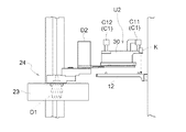
スタッカークレーン20は、図1及び図2に示すように、物品収納棚10Aの前面に左右方向に沿って敷設された走行レールR1上を走行する台車部21と、台車部21に立設された昇降マスト22と、昇降マスト22に沿って昇降可能な昇降体23と、を備えている。また、移載フォーク25は、昇降体23に支持されて、スカラアーム24によって昇降体23に対して出退可能に構成されている。
As shown in FIGS. 1 and 2, the stacker crane 20 is erected on a
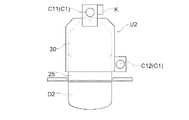
収納用支持体12は、平面視で矩形状の部材に移動用空間W側が開口するU字状の切欠き部12Kが形成され、収納用支持体12の上面側で且つ切欠き部12Kの周囲に容器Bの底部に備えられた位置決め用の溝部と係合する3つの位置決めピンPが分散して配置されている。収納用支持体12の開口側端部12EにはターゲットマークTが取り付けられている。
位置決めピンPは、図3及び図4に示すように、物品収納棚10Aと移動用空間Wとの並び方向である前後方向(図4のZ方向)で移動用空間W側に位置し且つ左右方向で切欠き部12Kの存在領域の左側に位置する第3ピンP3と、前後方向で移動用空間W側に位置し且つ左右方向で切欠き部の右側に位置する第2ピンP2と、前後方向で移動用空間Wから離間する奥側に位置し且つ左右方向で切欠き部存在領域のほぼ中央に位置する第1ピンP1と、を備えている。
The
As shown in FIGS. 3 and 4, the positioning pin P is located on the moving space W side in the front-rear direction (the Z direction in FIG. 4), which is the direction in which the article storage shelf 10 </ b> A and the moving space W are arranged. A third pin P3 located on the left side of the region where the
また、図示は省略するが、容器Bの底部には、当該容器Bを収納用支持体12に支持したときに第1ピンP1と係合する第1溝部、第2ピンP2と係合する第2溝部、第3ピンP3と係合する第3溝部が設けられ、この3つの溝部とに第1ピンP1〜に第3ピンP3の係合によって、容器Bが平面視で収納用支持体12に対して所定の位置(適正収納位置)となるように位置決めされるようになっている。本実施形態において、位置決めピンP(第1ピンP1〜に第3ピンP3)が位置決め部材に相当する。すなわち、収納用支持体12は、容器Bを適正収納位置に位置決めする位置決めピンPを平面視で分散して備えている。
Although not shown, the bottom of the container B has a first groove that engages with the first pin P1 when the container B is supported by the
さらに、図示は省略するが、容器Bの底面には、不活性気体を当該容器Bの内部に導入するための孔部を備えた接続部が設けられ、収納用支持体12の上面には、支持姿勢の容器Bの接続部に接続されて不活性気体を供給する不活性気体供給部が設けられている。
不活性気体供給部は、例えばシリコーン樹脂等で形成された緩衝体が設けられ、容器Bを受け渡す際に接続部と不活性気体供給部とが接触したときの衝撃を吸収するようになっている。
Further, although not shown in the figure, the bottom surface of the container B is provided with a connecting portion having a hole for introducing an inert gas into the container B, and the top surface of the
The inert gas supply unit is provided with a buffer formed of, for example, a silicone resin and absorbs an impact when the connection unit and the inert gas supply unit come into contact with each other when the container B is delivered. Yes.
移載フォーク25の上面には位置決めピンQが分散して配置されている。位置決めピンQは、第1溝部に係合する第1ピンQ1、第2溝部に係合する第2ピンQ2、及び、第3溝部に係合する第3ピンQ3とから構成される。移載フォーク25は、位置決めピンQによって、移載フォーク25における適正な支持用位置に位置決めした状態で、容器Bを支持するようになっている。
Positioning pins Q are distributed on the upper surface of the
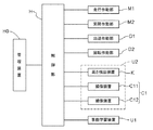
スタッカークレーン20には、図5に示すように、台車部21を走行作動させる走行作動部M1、昇降体23を昇降作動させる昇降作動部M2、スカラアーム24を操作して移載フォーク25を前後方向に出退移動させる出退作動部D1、スカラアーム24の先端に設けられた上下方向に沿う回転軸周りで移載フォーク25を回転作動させる回転作動部D2とが設けられ、これら走行作動部M1、昇降作動部M2、出退作動部D1、及び回転作動部D2は、スタッカークレーン20の作動を制御する制御部Hに接続されてその作動を制御されるようになっている。なお、走行作動部M1、昇降作動部M2、出退作動部D1、及び回転作動部D2から制御部Hにはそれらの作動量を示すフィードバック情報が入力されており、制御部Hは、必要な作動量だけ走行作動部M1、昇降作動部M2、出退作動部D1、及び回転作動部D2を作動させることができるようになっている。
As shown in FIG. 5, the stacker crane 20 moves the
本実施形態においては、移載フォーク25が移動支持体に相当し、スタッカークレーン20に備える走行作動部M1、昇降作動部M2、出退作動部D1、及び回転作動部D2が移動機構に相当する。すなわち、物品収納棚10Aの前面に沿って設けられた移動用空間Wにおいて移載フォーク25を上下方向(Y方向)及び左右方向(X方向)に移動させるとともに、移動用空間Wと物品収納棚10Aとの並び方向である前後方向(Z方向)に沿って移載フォーク25を移動させる移動機構と、移動機構を制御する制御部Hとが設けられている。
In the present embodiment, the
また、図5に示すように、制御部Hには、収納部Sへの容器Bの搬入または搬出を指令する管理装置H0が制御部Hと通信可能に接続されている。加えて、制御部Hには、後述する学習装置U2に備えるレーザー測距計等の高さ検出装置Kの検出情報と、第1撮像装置C11及び第2撮像装置C12の撮像画像が入力されるようになっている。さらに、制御部Hには、後述する事前学習装置U1に備える第1撮像装置C21及び第2撮像装置C22の撮像画像が入力されるようになっている。
さらに、制御部Hは、物品収納棚10Aに備える各収納部Sの夫々に対応して、当該収納部Sの収納用支持体12に容器Bを受け渡すときの移載フォーク25のX方向、Y方向、及びZ方向の夫々の位置を、収納部Sに対応付けて、自己が保持するデータベースに記憶している。以降、収納部Sに対応してデータベースが記憶している移載フォーク25のX方向、Y方向、及びZ方向の夫々の位置を、DB記憶位置と称する。
As shown in FIG. 5, the control unit H is connected to the control unit H so as to be communicable with the control unit H. The management device H0 commands the loading or unloading of the container B into the storage unit S. In addition, the detection information of the height detection device K such as a laser range finder provided in the learning device U2 described later and the captured images of the first imaging device C11 and the second imaging device C12 are input to the control unit H. It is like that. Furthermore, captured images of the first imaging device C21 and the second imaging device C22 provided in the pre-learning device U1 described later are input to the control unit H.
Further, the control unit H corresponds to each of the storage units S provided in the
そして、移載フォーク25から収納用支持体12に容器Bを受け渡す(卸す)場合には、制御部Hは、図2(a)に示すように、DB記憶位置を目標停止位置として、移載フォーク25を移動させるべく走行作動部M1及び昇降作動部M2を作動させて容器B受渡し対象の収納部Sの前面に移載フォーク25を位置させ、その後、出退作動部D1を作動させて移載フォーク25を収納部S側に突出させるべく、移動機構を制御する。すなわち、制御部Hは、複数の収納部Sの夫々に対応して設定された目標停止位置まで移載フォーク25を移動させ、当該目標停止位置に停止させる移動動作を移動機構に実行させる。
When the container B is transferred (shipped) from the
つづいて、図2(b)に示すように、制御部Hは、目標停止位置において移載フォーク25を図2(c)の位置まで下降させることにより、収納用支持体12に容器Bを受け渡す。すなわち、制御部Hは、目標停止位置において移載フォーク25を下降させて収納用支持体12に容器Bを受け渡す移載動作を移動機構に実行させる。
Subsequently, as shown in FIG. 2B, the control unit H lowers the
ところで、上記のDB記憶位置は、収納用支持体12が物品収納棚10Aの上下支柱に対して、適正な状態で取付けられていることを前提とした設計上の目標停止位置として設定されている。
目標停止位置をDB記憶位置に設定すると、DB記憶位置が適正であれば、DB記憶位置に位置する移載フォーク25と収納用支持体12との平面視での適正な位置関係は、図3(a)に示すように、平面視での位置決めピンPの配置が左右対称となる軸J1と、平面視での位置決めピンQの配置が左右対称となる軸J2とが重複するような位置関係となっている。このような位置関係となっているときには移載フォーク25が支持している容器Bを収納用支持体12における適正収納位置に移載動作により受け渡すことが可能である。このような移載フォーク25の位置を適正位置と称する。
By the way, the DB storage position is set as a design target stop position on the assumption that the
When the target stop position is set to the DB storage position, if the DB storage position is appropriate, the appropriate positional relationship in plan view between the
一方、収納用支持体12の取付け精度が悪い等の事情により、図3(b)に示すように、収納用支持体12が上記のような適正な状態で上下支柱に取付けられていない場合、すなわち平面視で軸J1と軸J2とが互いにΔθ傾斜している場合、DB記憶位置と実際に移載フォーク25が支持している容器Bを収納用支持体12における適正収納位置に移載動作により受け渡すことができる移載フォーク25のX方向、Y方向、及びZ方向の夫々の位置とがずれてしまう虞がある。このようなずれが生じたまま移載フォーク25が支持している容器Bを収納用支持体12に受け渡す場合、容器Bが備える位置決め用の溝部により容器Bが適正収納位置に案内されることになるが、適正収納位置まで案内される過程で振動が生じたり、不活性気体供給部の緩衝体が擦れて不純物粒子が発生したりする虞がある。
On the other hand, due to circumstances such as poor mounting accuracy of the
そこで、本実施形態では、各収納部Sの夫々に対して、目標停止位置に停止した移載フォーク25の位置が適正位置からずれている場合には、その位置ずれ量を算出して、目標停止位置を補正するようにしている。以降、このように目標停止位置の補正を行うことを、「学習」と称する。制御部Hは、物品収納棚10Aに備えるすべての収納部Sについて、予め定められた順序で学習を行う「学習運転」を実行可能に構成されている。
Therefore, in the present embodiment, when the position of the
学習に当たっては、図4に示す事前学習装置U1と、図6〜図8に示す学習装置U2とを用いる。事前学習装置U1は、図4に示すように、収納部Sの収納用支持体12を正面から撮像する第1撮像装置C21と、平面視で傾斜した方向から第1撮像装置C21と同じ箇所を撮像する第2撮像装置C22とを備えている。事前学習装置U1は、位置決めピンQによって移載フォーク25に対して位置決めされた状態で、移載フォーク25に装着可能となっている。
In learning, a pre-learning device U1 shown in FIG. 4 and a learning device U2 shown in FIGS. 6 to 8 are used. As shown in FIG. 4, the pre-learning device U1 includes the first imaging device C21 that images the
また、学習装置U2は、図6〜図8に示すように、収納用支持体12の上面に設けられる第1ピンP1を上方から撮像する第1撮像装置C11と、収納用支持体12の上面に設けられる第2ピンP2を上方から撮像する第2撮像装置C12と、収納用支持体12の上面までの距離を計測する高さ検出装置Kと、が固定状態で取付けられた基台部30を備えている。基台部30は、位置決めピンQによって移載フォーク25に対して位置決めされた状態で移載フォーク25に装着可能となっている。本実施形態では、学習装置U2の第1撮像装置C11及び第2撮像装置C12が撮像装置C1に相当し、高さ検出装置Kが上下距離計測部に相当する。すなわち、移載フォーク25は、撮像装置C1を着脱自在に構成され、撮像装置C1は、制御部Hに制御されて、移載フォーク25が目標停止位置にある状態で、当該目標停止位置に対応する収納部Sにおける収納用支持体12に設定された撮像対象箇所としての位置決めピンPを上方から撮像するように構成されている。また、移載フォーク25は、目標停止位置にある当該移載フォーク25と収納用支持体12との上下方向での距離である上下距離を計測するレーザー測距式の高さ検出装置Kを備えている。
Further, as shown in FIGS. 6 to 8, the learning device U <b> 2 includes a first imaging device C <b> 11 that images the first pin P <b> 1 provided on the upper surface of the
学習運転として、まず、事前学習装置U1を移載フォーク25に装着して、各収納部Sについての目標停止位置におけるX座標とY座標とを求める事前学習処理を行う。なお、事前学習装置U1を移載フォーク25に装着するに当たっては、移載フォーク25が備えるコネクタとの間で制御部Hとの通信ケーブルや電源ケーブルを接続することになるが、ここでは説明を割愛する。移載フォーク25に事前学習装置U1を装着後、制御部Hは、移載フォーク25をX方向及びY方向に移動させ、第1撮像装置C21及び第2撮像装置C22で収納用支持体12の開口側端部12Eに取付けられたターゲットマークTを撮像し、その撮像画像に基づいて目標停止位置におけるX方向、Y方向、Z方向の位置のうちX方向の位置とY方向の位置とを求める事前学習処理をすべての収納部Sについて行う。事前学習処理で求めたX方向及びY方向の位置は、DB記憶位置におけるX方向及びY方向の位置に上書きしてデータベースに記憶される。
As the learning operation, first, the pre-learning device U1 is attached to the
事前学習処理が完了すると、制御部Hは、引き続き仕上げ学習処理を行う。仕上げ学習処理は、学習装置U2を移載フォーク25に装着して行う。なお、学習装置U2を移載フォーク25に装着するに当たっては、移載フォーク25が備えるコネクタとの間で制御部Hとの通信ケーブルや電源ケーブルを接続することになるが、ここでは説明を割愛する。
When the pre-learning process is completed, the control unit H continues to perform the finishing learning process. The finishing learning process is performed by attaching the learning device U2 to the
以下、仕上げ学習処理における制御を図9のフローチャートに基づいて説明する。
仕上げ学習処理における学習の開始が指令されると(#11:Yes)、制御部Hは、学習対象の収納部S(学習対象収納部と称する)を設定する(#12)。そして、目標停止位置として学習対象収納部に対応するDB記憶位置に対してY方向に学習用設定高さ(例えば2〜5cm程度)を付加した位置を予備目標停止位置として、移載フォーク25を予備目標停止位置まで移動させ、当該予備目標停止位置に停止させる予備移動動作を移動機構に実行させる予備移動処理を実行する(#13)。
予備移動処理として、制御部Hは、移載フォーク25をY方向及びX方向に移動させる処理(第1移動処理)を実行した後に、当該移載フォーク25をZ方向に沿って移動させる処理(第2移動処理)を実行するように構成されている。
Hereinafter, the control in the finishing learning process will be described based on the flowchart of FIG.
When the start of learning in the finishing learning process is commanded (# 11: Yes), the control unit H sets a learning target storage unit S (referred to as a learning target storage unit) (# 12). Then, the
As the preliminary movement process, the control unit H performs a process (first movement process) for moving the
つづいて、制御部Hは、移載フォーク25を予備目標停止位置に停止させた状態で、撮像装置C1に撮像対象箇所を撮像させる撮像処理を行う(#14)。
そして、制御部Hは、#14の撮像処理により得られた撮像画像における実際の位置決めピンPの位置と、移載フォーク25が適正位置に位置している場合に撮像装置C1にて撮像した撮像画像における位置決めピンPの位置と、に基づいて、からの移載フォーク25のZ方向及びX方向の位置ずれ量を算出するずれ量算出処理を実行する(#15)。ここで、適正位置とは、移載フォーク25が支持している容器Bを収納用支持体12における適正収納位置に移載動作により受け渡すことが可能な当該移載フォーク25の位置である。また、ずれ量算出処理の実行に当たっては、撮像画像についてパターンマッチングを行っているが、この方法については既知であるため、ここでは説明を割愛する。
Subsequently, the control unit H performs an imaging process in which the imaging device C1 captures an imaging target location in a state where the
And the control part H imaged with the imaging device C1, when the position of the actual positioning pin P in the captured image obtained by the imaging process of # 14 and the
つづいて、制御部Hは、当該ずれ量算出処理により算出した位置ずれ量に基づいて、予備目標停止位置を補正して目標停止位置を設定し、当該目標停止位置の値によって上記DB記憶位置を上書きしてデータベースに記憶する補正処理を実行する(#16)。
また、補正処理に引き続き、制御部Hは、図12に示す高さずれ量確認処理を実行する(#17)。高さずれ量確認処理は、図12に示すように、高さ検出装置Kで検出した収納用支持体12の上面からの高さ情報に基づいて、適正位置の移載フォーク25と収納用支持体12との上下方向での距離である適正距離と、予備移動動作によって移載フォーク25が予備目標停止位置に位置している状態で高さ検出装置Kによって計測した上下距離と、の差である高さずれ量を算出する高さずれ算出処理(#41)を行い、当該収納部Sの識別情報と対応付けて記憶する(#42)。制御部Hは、高さずれ算出処理にて算出した高さずれ量が許容量より大きい異常高さ状態である場合(#43:Yes)は、当該収納部における収納用支持体12の取付状態が異常となっていると判別して、当該収納部Sを使用禁止とするようにデータベースに記憶する(#44)。異常高さ状態でない場合、及び、#44の処理が終了すると、高さずれ量確認処理のルーチンを抜けてリターンする。
Subsequently, the control unit H corrects the preliminary target stop position based on the position shift amount calculated by the shift amount calculation process, sets the target stop position, and sets the DB storage position based on the value of the target stop position. Correction processing overwritten and stored in the database is executed (# 16).
Further, following the correction process, the control unit H executes a height deviation amount confirmation process shown in FIG. 12 (# 17). As shown in FIG. 12, the height deviation amount confirmation processing is performed based on the height information from the upper surface of the
その後、制御部Hは、学習を終了するか否かを判別する(#18)。なお、学習を終了する条件としては、すべての収納部Sについて学習を完了した、又は、学習対象として指定された収納部Sについての学習を完了した等の条件を満たした場合である。#17において学習を終了すると判別した場合(#18:Yes)は、学習運転を終了する。また、学習運転を終了しないと判別した場合(#18:No)は、学習対象の収納部Sを、予め定められた順序において次に予定される収納部に変更し(#19)、続いて#13の予備移動処理に戻る。また、#11において、学習開始を指令されなかった場合(#11:No)は、処理を終了する。 Thereafter, the control unit H determines whether or not to end learning (# 18). The condition for ending the learning is a case where the learning is completed for all the storage units S or the learning is completed for the storage unit S designated as a learning target. If it is determined in # 17 that learning is to be terminated (# 18: Yes), the learning operation is terminated. If it is determined that the learning operation is not finished (# 18: No), the storage unit S to be learned is changed to the storage unit scheduled next in a predetermined order (# 19), and then The process returns to the # 13 preliminary movement process. Further, when the learning start is not instructed in # 11 (# 11: No), the process is terminated.
ここで、ずれ量算出処理の概略を図10に基づいて説明する。
図10(a)は、収納用支持体12が適正に取付けられていた場合の第1ピンP11及び第2ピンP21の平面視位置(補正前位置と称する)と、撮像処理によって取得した撮像画像における実際の第1ピンP11及び第2ピンP21の平面視位置(補正後位置と称する)とを同一平面状にプロットした図である。
これより分かるように、補正後位置は補正前位置に対してZ方向でΔzずれていると同時に、補正前位置における軸J1と重複する仮想線KL1と補正後位置における軸J1と重複する仮想線KL2とが平面視で互いに角度Δθだけ傾斜している。
Here, an outline of the shift amount calculation processing will be described with reference to FIG.
FIG. 10A shows a plan view position (referred to as a pre-correction position) of the first pin P11 and the second pin P21 when the
As can be seen, the post-correction position is shifted by Δz in the Z direction with respect to the pre-correction position, and at the same time, the virtual line KL1 overlapping the axis J1 at the pre-correction position and the virtual line overlapping the axis J1 at the post-correction position. KL2 is inclined with respect to each other by an angle Δθ in plan view.
この場合の位置ずれ量を算出するために、図10(b)に示すように、まず、仮想線KL1と仮想線KL2とが平行となるように補正前位置をプロットした平面を角度Δθだけ回転操作する。その後、図10(c)に示すようにΔz分だけZ方向に並進操作することによって、補正前位置での第1ピンP11と補正後位置での第1ピンP12、及び、補正前位置での第2ピンP21と補正後位置での第2ピンP22とを重複させる。
このとき、図10(c)に示すように、仮想線KL1から算出される移載フォーク25基端部のX方向の位置ずれはΔx2となり、補正後位置での仮想線KL2の出退方向での位置ずれはΔz2となる。
したがって、予備目標停止位置をΔx2及びΔz2で補正することによって、目標停止位置を補正することができる。
In order to calculate the displacement amount in this case, as shown in FIG. 10B, first, the plane on which the pre-correction position is plotted is rotated by an angle Δθ so that the virtual line KL1 and the virtual line KL2 are parallel to each other. Manipulate. Then, as shown in FIG. 10C, by performing translation operation in the Z direction by Δz, the first pin P11 at the pre-correction position, the first pin P12 at the post-correction position, and the position at the pre-correction position. The second pin P21 and the second pin P22 at the corrected position are overlapped.
At this time, as shown in FIG. 10C, the positional deviation in the X direction of the base end portion of the
Therefore, the target stop position can be corrected by correcting the preliminary target stop position with Δx2 and Δz2.
〔別実施形態〕
(1)上記実施形態では、補正処理として、物品収納棚10Aにおける全ての収納部Sに対して事前学習処理及び仕上げ学習処理を順次行って、DB記憶位置を更新記憶する例を示したが、補正処理として、全ての収納部Sのうち指定した収納部Sのみについて事前学習処理及び仕上げ学習処理を行う構成としてもよい。
[Another embodiment]
(1) In the above embodiment, as the correction process, the example in which the preliminary learning process and the finish learning process are sequentially performed on all the storage units S in the
(2)上記実施形態では、学習装置U2にレーザー測距式の高さ検出装置Kを備える構成としたが、高さ検出装置Kとしてレーザー測距式以外の方式のものを用いてもよい。例えば、下方に向けてプローブ端子を伸縮自在に構成し、プローブ端子が収納用支持体12の上面に接触した位置をもって移載フォーク25と収納用支持体12との上下距離を計測するように構成下もよい。また、高さ検出装置Kを学習装置U2ではなく移載フォーク25に備えることも可能である。さらに、高さ検出装置Kを何れにも備えない構成としてもよい。
(2) In the above embodiment, the learning device U2 includes the laser distance measurement type height detection device K. However, the height detection device K may be of a system other than the laser distance measurement type. For example, the probe terminal is configured to be extendable downward, and the vertical distance between the
(3)上記実施形態では、制御部Hが、撮像画像における位置決めピンPの位置に基づいてずれ量算出処理を実行する構成を説明したが、撮像画像における位置決めピンP以外の構成の位置に基づいてずれ量算出処理を実行してもよい。すなわち、例えば矩形状で切欠き部12Kが設けられた収納用支持体12の全体を撮像対象箇所とし、当該収納用支持体12の形状に基づいてずれ量算出処理を実行することができる。このように、撮像画像上でずれ量を判別可能な部分が存在すれば、それに基づいてずれ量算出処理を実行することが可能である。
(3) In the above embodiment, the configuration in which the control unit H executes the shift amount calculation processing based on the position of the positioning pin P in the captured image has been described. However, based on the position of the configuration other than the positioning pin P in the captured image. The deviation amount calculation process may be executed. That is, for example, the
(4)上記実施形態において、学習装置U2に収納用支持体12に対する移載フォーク25のY方向及びX方向の位置が適正正面位置であることを検出する検出装置を備えさせる構成としてもよい。このような構成として、収納用支持体12における所定の箇所に取付けられた反射体を検出するレーザー検出装置を用いてもよい。この構成によって、適正正面位置を反射体の位置に基づいて検出することができる。この場合、学習運転を、図11のフローチャートに示す処理とすることができる。このフローチャートでは、図9のフローチャートの#13〜#16の処理を#23〜#29及び#31の処理に変更している。すなわち学習対象の収納部Sを設定(#22)し、第1移動処理を実行する(#23)。そして、第1移動処理の実行後でかつ第2移動処理の実行前に、移載フォーク25に装着された検出装置の検出情報に基づいて、第2移動処理の実行の可否を判別する第2移動可否判別処理を実行する(#24)。
(4) In the above-described embodiment, the learning device U2 may include a detection device that detects that the positions of the
第2移動可否判別処理において第2移動処理が可と判別された場合(#25:Yes)には、引き続き、第2移動処理(#26)、撮像処理(#27)、ずれ量算出処理(#28)、及び補正処理(#29)を実行する。引き続き、制御部Hは、図12の高さずれ量確認処理(#30)を実行する。 If it is determined that the second movement process is possible in the second movement availability determination process (# 25: Yes), the second movement process (# 26), the imaging process (# 27), and the deviation amount calculation process ( # 28) and correction processing (# 29) are executed. Subsequently, the controller H executes the height deviation amount confirmation process (# 30) of FIG.
第2移動可否判別処理において第2移動処理が可と判別されなかった場合(#25:No)には、その収納用支持体12を非学習支持体としてデータベースに記憶させる(#32)、#31の処理に進む。非学習支持体としてデータベースに記憶された収納用支持体12は、例えば、改修が必要な収納用支持体12として記憶され、制御部Hは、その後改修されて第2移動処理が可と判別される状態にならない限り、当該収納用支持体12を有する収納部Sを、容器Bを収納する収納対象の収納部Sとして引き当てないように構成されることが望ましい。
なお、事前学習装置U1によってX方向の位置及びY方向の位置を予備目標停止位置として取得する場合は、事前学習処理によって既に第2移動処理をさせることが可能なX方向及びY方向の位置がデータベースに更新記憶されていると考えられるため、#24の第2移動可否判別処理を実行せずに、第1移動処理に引き続いて第2移動処理を実行するようにしてもよい。
If the second movement process is not determined to be possible in the second movement determination process (# 25: No), the
In addition, when the position in the X direction and the position in the Y direction are acquired as the preliminary target stop positions by the pre-learning device U1, there are positions in the X direction and the Y direction that can be already subjected to the second movement process by the pre-learning process. Since it is considered that the data is updated and stored in the database, the second movement process may be executed subsequent to the first movement process without executing the second movement availability determination process of # 24.
(5)上記実施形態及び上記別実施形態(4)では、高さずれ量算出処理で算出した高さずれ量を収納部Sの識別情報と対応付けて記憶し、高さずれ量算出処理にて算出した高さずれ量が許容量より大きい異常高さ状態である場合は、当該収納部における収納用支持体12の取付状態が異常となっていると判別して、当該収納部Sを使用禁止とするようにデータベースに記憶する例を示したが、このような処理に加えて、高さずれ量算出処理にて算出した高さずれ量が許容量より大きい異常高さ状態でない場合には、高さずれ量に基づいて予備目標停止位置を補正して目標停止位置を設定する高さ補正処理を実行するように構成してもよい。
また、上記実施形態及び上記別実施形態(4)では、学習処理において高さずれ量確認処理を実行する形態を記載したが、高さずれ量確認処理を実行しない構成としてもよい。
(5) In the above embodiment and another embodiment (4), the height deviation amount calculated in the height deviation amount calculation process is stored in association with the identification information of the storage unit S, and the height deviation amount calculation process is performed. If the height deviation amount calculated in the above is an abnormal height state larger than the allowable amount, it is determined that the mounting state of the
Further, in the above-described embodiment and the above-described another embodiment (4), the form in which the height deviation amount confirmation process is executed in the learning process is described. However, the height deviation amount confirmation process may not be executed.
(6)上記実施形態では、制御部Hが、学習処理において事前学習装置U1によって学習したX方向の位置及びY方向の位置を予備目標停止位置として取得する例を説明したが、このような構成に限定されるものではなく、例えば、事前学習装置U1による学習は行わず、物品収納棚10Aの設計時におけるX方向の位置及びY方向の位置を予備目標停止位置として取得するように構成してもよい。
(6) In the above-described embodiment, an example has been described in which the control unit H acquires the position in the X direction and the position in the Y direction learned by the pre-learning device U1 in the learning process as the preliminary target stop position. For example, the learning by the pre-learning device U1 is not performed and the position in the X direction and the position in the Y direction at the time of designing the
10A 物品収納棚
12 収納用支持体
25 移載フォーク(移動支持体)
B 容器(物品)
C1 撮像装置
D1 出退作動部(移動機構)
D2 回転作動部(移動機構)
M1 走行作動部(移動機構)
M2 昇降作動部(移動機構)
H 制御部
K 高さ検出装置
P 位置決めピン(位置決め部材)
S 収納部
W 移動用空間
10A
B Container (goods)
C1 imaging device D1 exit / retreat operation unit (movement mechanism)
D2 Rotation actuator (movement mechanism)
M1 traveling operation part (movement mechanism)
M2 lifting / lowering actuator (moving mechanism)
H Control part K Height detection device P Positioning pin (positioning member)
S storage part W space for movement
Claims (7)
前記物品を支持する移動支持体と、
前記物品収納棚の前面に沿って設けられた移動用空間において前記移動支持体を前記上下方向及び前記左右方向に移動させるとともに、前記移動用空間と前記物品収納棚との並び方向である前後方向に沿って前記移動支持体を移動させる移動機構と、
前記移動機構を制御する制御部と、を備え、
前記制御部は、
複数の前記収納部の夫々に対応して設定された目標停止位置まで前記移動支持体を移動させ、当該目標停止位置に停止させる移動動作と、前記目標停止位置において前記移動支持体を下降させて前記収納用支持体に前記物品を受け渡す移載動作と、を前記移動機構に実行させる物品収納設備であって、
前記移動支持体は、撮像装置を着脱自在に構成され、前記収納用支持体に対する前記移動支持体の前記上下方向及び前記左右方向の位置が、前記前後方向に沿って前記移動支持体を移動させることが許容される適正正面位置であることを検出する検出装置を備え、
前記撮像装置は、前記制御部に制御されて、前記移動支持体が前記目標停止位置にある状態で、当該目標停止位置に対応する前記収納部における前記収納用支持体に設定された撮像対象箇所を上方又は下方から撮像するように構成され、
前記制御部は、
前記撮像装置が装着された状態の前記移動支持体を、前記目標停止位置として予め設定された予備目標停止位置まで移動させ、当該予備目標停止位置に停止させる予備移動動作を、前記移動機構に実行させる予備移動処理と、
前記移動支持体を前記予備目標停止位置に停止させた状態で、前記撮像装置に前記撮像対象箇所を撮像させる撮像処理と、
前記撮像処理により得られた撮像画像に基づいて、前記移動支持体が支持している物品を前記収納用支持体における適正収納位置に前記移載動作により受け渡すことが可能な当該移動支持体の位置である適正位置からの前記移動支持体の前記前後方向及び前記左右方向の位置ずれ量を算出するずれ量算出処理と、
前記ずれ量算出処理により算出した前記位置ずれ量に基づいて、前記予備目標停止位置を補正して前記目標停止位置を設定する補正処理と、を実行するように構成されると共に、
前記予備移動処理として前記移動支持体を前記上下方向及び前記左右方向に移動させる第1移動処理を実行した後に、当該移動支持体を前記前後方向に沿って移動させる第2移動処理を実行するように構成され、かつ、前記第1移動処理の実行後でかつ前記第2移動処理の実行前に、前記移動支持体に装着された前記検出装置の検出情報に基づいて前記第2移動処理の実行の可否を判別する第2移動可否判別処理を実行するように構成され、
さらに、前記制御部は、前記第2移動可否判別処理において前記第2移動処理の実行が可と判別された場合には前記第2移動処理の実行を開始し、前記第2移動処理の実行が不可と判別された場合は、前記第2移動処理の実行を開始しない物品収納設備。 A shelf in which a plurality of storage units are arranged side by side in the up-down direction and the left-right direction, each of the storage units includes a storage support that supports the article from below,
A moving support for supporting the article;
In the movement space provided along the front surface of the article storage shelf, the movement support is moved in the vertical direction and the left-right direction, and the front-rear direction is an arrangement direction of the movement space and the article storage shelf. A moving mechanism for moving the movable support along
A control unit for controlling the moving mechanism,
The controller is
Moving the moving support body to a target stop position set corresponding to each of the plurality of storage units, and stopping the mobile support body at the target stop position; and lowering the moving support body at the target stop position. An article storage facility for causing the moving mechanism to perform a transfer operation of delivering the article to the storage support;
The moving support is configured to be detachable from the imaging device, and the vertical and horizontal positions of the moving support relative to the storage support move the moving support along the front-rear direction. A detection device that detects that the front position is acceptable and
The imaging device is controlled by the control unit, and in a state where the moving support is at the target stop position, an imaging target location set in the storage support in the storage corresponding to the target stop position Configured to image from above or below,
The controller is
The moving mechanism is moved to the preliminary target stop position set in advance as the target stop position, and the preliminary movement operation for stopping at the preliminary target stop position is performed on the moving mechanism. A preliminary movement process
An imaging process for causing the imaging device to image the imaging target location in a state where the movable support is stopped at the preliminary target stop position;
Based on the captured image obtained by the imaging process, the moving support body can transfer the article supported by the moving support body to an appropriate storage position in the storage support body by the transfer operation. A displacement amount calculation process for calculating a displacement amount in the front-rear direction and the left-right direction of the movable support from an appropriate position as a position;
The deviation amount calculation process based on the positional deviation amount calculated by the correction processing for setting the target stop position by correcting the preliminary target stop position, is configured to run Rutotomoni,
As the preliminary movement process, after performing the first movement process for moving the moving support body in the up-down direction and the left-right direction, the second movement process for moving the movement support body in the front-rear direction is performed. And the execution of the second movement process based on the detection information of the detection device mounted on the movement support after the execution of the first movement process and before the execution of the second movement process. Configured to execute a second movement availability determination process for determining whether or not
Further, the control unit starts executing the second movement process when it is determined in the second movement availability determination process that the second movement process can be executed, and the second movement process is executed. The article storage facility that does not start the execution of the second movement process when it is determined as impossible .
前記物品を支持する移動支持体と、
前記物品収納棚の前面に沿って設けられた移動用空間において前記移動支持体を前記上下方向及び前記左右方向に移動させるとともに、前記移動用空間と前記物品収納棚との並び方向である前後方向に沿って前記移動支持体を移動させる移動機構と、
前記移動機構を制御する制御部と、を備え、
前記制御部は、
複数の前記収納部の夫々に対応して設定された目標停止位置まで前記移動支持体を移動させ、当該目標停止位置に停止させる移動動作と、前記目標停止位置において前記移動支持体を下降させて前記収納用支持体に前記物品を受け渡す移載動作と、を前記移動機構に実行させる物品収納設備であって、
前記移動支持体は、撮像装置を着脱自在に構成され、前記目標停止位置にある当該移動支持体と前記収納用支持体との前記上下方向での距離である上下距離を計測する上下距離計測部を備え、
前記撮像装置は、前記制御部に制御されて、前記移動支持体が前記目標停止位置にある状態で、当該目標停止位置に対応する前記収納部における前記収納用支持体に設定された撮像対象箇所を上方又は下方から撮像するように構成され、
前記制御部は、
前記撮像装置が装着された状態の前記移動支持体を、前記目標停止位置として予め設定された予備目標停止位置まで移動させ、当該予備目標停止位置に停止させる予備移動動作を、前記移動機構に実行させる予備移動処理と、
前記移動支持体を前記予備目標停止位置に停止させた状態で、前記撮像装置に前記撮像対象箇所を撮像させる撮像処理と、
前記撮像処理により得られた撮像画像に基づいて、前記移動支持体が支持している物品を前記収納用支持体における適正収納位置に前記移載動作により受け渡すことが可能な当該移動支持体の位置である適正位置からの前記移動支持体の前記前後方向及び前記左右方向の位置ずれ量を算出するずれ量算出処理と、
前記ずれ量算出処理により算出した前記位置ずれ量に基づいて、前記予備目標停止位置を補正して前記目標停止位置を設定する補正処理と、を実行するように構成されると共に、
前記適正位置の前記移動支持体と前記収納用支持体との前記上下方向での距離である適正距離と、前記予備移動動作によって前記移動支持体が前記予備目標停止位置に位置している状態で前記上下距離計測部によって計測した前記上下距離と、の差である高さずれ量を算出する高さずれ量算出処理、及び、前記高さずれ量算出処理により算出した前記高さずれ量が許容量より大きい異常高さ状態であるか否かを判別する異常判別処理を実行するように構成されている物品収納設備。 A shelf in which a plurality of storage units are arranged side by side in the up-down direction and the left-right direction, each of the storage units includes a storage support that supports the article from below,
A moving support for supporting the article;
In the movement space provided along the front surface of the article storage shelf, the movement support is moved in the vertical direction and the left-right direction, and the front-rear direction is an arrangement direction of the movement space and the article storage shelf. A moving mechanism for moving the movable support along
A control unit for controlling the moving mechanism,
The controller is
Moving the moving support body to a target stop position set corresponding to each of the plurality of storage units, and stopping the mobile support body at the target stop position; and lowering the moving support body at the target stop position. An article storage facility for causing the moving mechanism to perform a transfer operation of delivering the article to the storage support;
The moving support is configured to be detachable from the imaging device, and a vertical distance measuring unit that measures a vertical distance that is a distance in the vertical direction between the moving support at the target stop position and the storage support. With
The imaging device is controlled by the control unit, and in a state where the moving support is at the target stop position, an imaging target location set in the storage support in the storage corresponding to the target stop position Configured to image from above or below,
The controller is
The moving mechanism is moved to the preliminary target stop position set in advance as the target stop position, and the preliminary movement operation for stopping at the preliminary target stop position is performed on the moving mechanism. A preliminary movement process
An imaging process for causing the imaging device to image the imaging target location in a state where the movable support is stopped at the preliminary target stop position;
Based on the captured image obtained by the imaging process, the moving support body can transfer the article supported by the moving support body to an appropriate storage position in the storage support body by the transfer operation. A displacement amount calculation process for calculating a displacement amount in the front-rear direction and the left-right direction of the movable support from an appropriate position as a position;
The deviation amount calculation process based on the positional deviation amount calculated by the correction processing for setting the target stop position by correcting the preliminary target stop position, is configured to run Rutotomoni,
In the state where the movable support is positioned at the preliminary target stop position by the preliminary movement and the proper distance that is the distance in the vertical direction between the movable support and the storage support at the proper position. The height deviation amount calculation process for calculating a height deviation amount that is a difference between the vertical distance measured by the vertical distance measurement unit and the height deviation amount calculated by the height deviation amount calculation process is permitted. An article storage facility configured to execute an abnormality determination process for determining whether or not an abnormal height state is greater than a capacity .
視で分散して備え、
前記撮像装置は、前記位置決め部材が設けられた箇所を前記撮像対象箇所として、当該
撮像対象箇所を撮像するように構成され、
前記制御部は、前記撮像画像における実際の前記位置決め部材の位置と、前記移動支持
体が前記適正位置に位置している場合に前記撮像装置にて撮像した前記撮像画像における
前記位置決め部材の位置と、に基づいて、前記ずれ量算出処理を実行する請求項1〜3の何れか1項に記載の物品収納設備。 The storage support includes a positioning member for positioning the article at the proper storage position in a plan view,
The imaging device is configured to take an image of the imaging target location using the location where the positioning member is provided as the imaging target location,
The control unit includes: an actual position of the positioning member in the captured image; and a position of the positioning member in the captured image captured by the imaging device when the movable support is positioned at the appropriate position. The article storage facility according to any one of claims 1 to 3 , wherein the shift amount calculation process is executed based on the information .
前記物品を支持する移動支持体と、
前記物品収納棚の前面に沿って設けられた移動用空間において前記移動支持体を前記上下方向及び前記左右方向に移動させるとともに、前記移動用空間と前記物品収納棚との並び方向である前後方向に沿って前記移動支持体を移動させる移動機構と、
前記移動機構を制御する制御部と、を備え、
前記制御部は、
複数の前記収納部の夫々に対応して設定された目標停止位置まで前記移動支持体を移動させ、当該目標停止位置に停止させる移動動作と、前記目標停止位置において前記移動支持体を下降させて前記収納用支持体に前記物品を受け渡す移載動作と、を前記移動機構に実行させる物品収納設備であって、
前記移動支持体は、撮像装置を着脱自在に構成され、前記物品を適正な支持用位置に位置決めする第1位置決め部材を平面視で分散して備え、
前記収納用支持体は、前記物品を前記適正収納位置に位置決めする第2位置決め部材を平面視で分散して備え、
前記撮像装置は、前記第1位置決め部材によって移動支持体に対して位置決めされると共に、前記制御部に制御されて、前記移動支持体が前記目標停止位置にある状態で、当該目標停止位置に対応する前記収納部の前記収納用支持体における前記第2位置決め部材が設けられた箇所を撮像対象箇所として、当該撮像対象箇所を上方から撮像するように構成され、
前記制御部は、
前記撮像装置が装着された状態の前記移動支持体を、前記目標停止位置として予め設定された予備目標停止位置まで移動させ、当該予備目標停止位置に停止させる予備移動動作を、前記移動機構に実行させる予備移動処理と、
前記移動支持体を前記予備目標停止位置に停止させた状態で、前記撮像装置に前記撮像対象箇所を撮像させる撮像処理と、
前記撮像処理により得られた撮像画像に基づいて、前記移動支持体が支持している物品を前記収納用支持体における適正収納位置に前記移載動作により受け渡すことが可能な当該移動支持体の位置である適正位置からの前記移動支持体の前記前後方向及び前記左右方向の位置ずれ量を算出するずれ量算出処理と、
前記ずれ量算出処理により算出した前記位置ずれ量に基づいて、前記予備目標停止位置を補正して前記目標停止位置を設定する補正処理と、を実行するように構成されている物品収納設備。 A shelf in which a plurality of storage units are arranged side by side in the up-down direction and the left-right direction, each of the storage units includes a storage support that supports the article from below,
A moving support for supporting the article;
In the movement space provided along the front surface of the article storage shelf, the movement support is moved in the vertical direction and the left-right direction, and the front-rear direction is an arrangement direction of the movement space and the article storage shelf. A moving mechanism for moving the movable support along
A control unit for controlling the moving mechanism,
The controller is
Moving the moving support body to a target stop position set corresponding to each of the plurality of storage units, and stopping the mobile support body at the target stop position; and lowering the moving support body at the target stop position. An article storage facility for causing the moving mechanism to perform a transfer operation of delivering the article to the storage support;
The movable support is configured to be detachable from an imaging device, and includes first positioning members that are positioned in proper support positions and dispersed in a plan view.
The storage support includes a second positioning member for positioning the article at the proper storage position in a plan view,
The imaging device is positioned with respect to the moving support by the first positioning member and controlled by the control unit so as to correspond to the target stop position in a state where the moving support is at the target stop position. wherein a portion of the second positioning member is provided in the housing for support of the housing portion as an imaging target portion, it is configured to image the imaging target portion from above to,
The controller is
The moving mechanism is moved to the preliminary target stop position set in advance as the target stop position, and the preliminary movement operation for stopping at the preliminary target stop position is performed on the moving mechanism. A preliminary movement process
An imaging process for causing the imaging device to image the imaging target location in a state where the movable support is stopped at the preliminary target stop position;
Based on the captured image obtained by the imaging process, the moving support body can transfer the article supported by the moving support body to an appropriate storage position in the storage support body by the transfer operation. A displacement amount calculation process for calculating a displacement amount in the front-rear direction and the left-right direction of the movable support from an appropriate position as a position;
An article storage facility configured to execute correction processing for correcting the preliminary target stop position and setting the target stop position based on the positional shift amount calculated by the shift amount calculation processing.
前記基台部は、前記第1位置決め部材によって前記移動支持体に対して位置決めされた状態で前記移動支持体に装着可能に構成されている請求項5に記載の物品収納設備。 The article storage facility according to claim 5, wherein the base is configured to be attachable to the moving support in a state where the base is positioned with respect to the moving support by the first positioning member.
Priority Applications (4)
| Application Number | Priority Date | Filing Date | Title |
|---|---|---|---|
| JP2015077897A JP6332115B2 (en) | 2015-04-06 | 2015-04-06 | Goods storage equipment |
| KR1020160041596A KR102418497B1 (en) | 2015-04-06 | 2016-04-05 | Article storage facility |
| US15/091,662 US9669996B2 (en) | 2015-04-06 | 2016-04-06 | Article storage facility |
| TW105110756A TWI667180B (en) | 2015-04-06 | 2016-04-06 | Article storage facility |
Applications Claiming Priority (1)
| Application Number | Priority Date | Filing Date | Title |
|---|---|---|---|
| JP2015077897A JP6332115B2 (en) | 2015-04-06 | 2015-04-06 | Goods storage equipment |
Publications (3)
| Publication Number | Publication Date |
|---|---|
| JP2016196360A JP2016196360A (en) | 2016-11-24 |
| JP2016196360A5 JP2016196360A5 (en) | 2017-01-05 |
| JP6332115B2 true JP6332115B2 (en) | 2018-05-30 |
Family
ID=57016898
Family Applications (1)
| Application Number | Title | Priority Date | Filing Date |
|---|---|---|---|
| JP2015077897A Active JP6332115B2 (en) | 2015-04-06 | 2015-04-06 | Goods storage equipment |
Country Status (4)
| Country | Link |
|---|---|
| US (1) | US9669996B2 (en) |
| JP (1) | JP6332115B2 (en) |
| KR (1) | KR102418497B1 (en) |
| TW (1) | TWI667180B (en) |
Families Citing this family (15)
| Publication number | Priority date | Publication date | Assignee | Title |
|---|---|---|---|---|
| JP6891898B2 (en) * | 2016-10-07 | 2021-06-18 | 村田機械株式会社 | Automatic warehouse |
| EP3530592A4 (en) * | 2016-10-18 | 2020-07-01 | Murata Machinery, Ltd. | Stacker crane |
| JP6597551B2 (en) * | 2016-10-21 | 2019-10-30 | 株式会社ダイフク | Goods transport equipment |
| EP3453646A1 (en) * | 2017-09-11 | 2019-03-13 | Nekos Oy | System for storing storage units |
| JP6924112B2 (en) * | 2017-09-29 | 2021-08-25 | 川崎重工業株式会社 | A method for obtaining the positional relationship between the board transfer device and the board transfer robot and the board mounting portion. |
| US20220371821A1 (en) | 2017-11-14 | 2022-11-24 | Hai Robotics Co., Ltd. | Handling robot |
| US11465840B2 (en) | 2017-11-14 | 2022-10-11 | Hai Robotics Co., Ltd. | Handling robot |
| US11396424B2 (en) | 2017-11-14 | 2022-07-26 | Hai Robotics Co., Ltd. | Handling robot |
| AU2018368407B2 (en) | 2017-11-14 | 2021-08-12 | Hai Robotics Co., Ltd. | Handling robot and method for retrieving inventory item based on handling robot |
| US11597598B2 (en) | 2019-02-01 | 2023-03-07 | Hai Robotics Co., Ltd. | Handling robot |
| US11542135B2 (en) | 2019-02-01 | 2023-01-03 | Hai Robotics Co., Ltd. | Handling robot |
| JP7238612B2 (en) * | 2019-06-04 | 2023-03-14 | 村田機械株式会社 | Camera attitude deviation evaluation method and camera system |
| JP7453114B2 (en) | 2020-09-29 | 2024-03-19 | 株式会社Fuji | Measuring device, transfer device, and measuring method |
| JP7322924B2 (en) | 2021-05-28 | 2023-08-08 | 株式会社ダイフク | Goods storage facility |
| CN117916683A (en) * | 2021-09-09 | 2024-04-19 | 村田机械株式会社 | Traveling vehicle system and traveling vehicle |
Family Cites Families (15)
| Publication number | Priority date | Publication date | Assignee | Title |
|---|---|---|---|---|
| KR940006241A (en) * | 1992-06-05 | 1994-03-23 | 이노우에 아키라 | Substrate transfer device and transfer method |
| TW314630B (en) * | 1994-06-30 | 1997-09-01 | Hitachi Ltd | |
| JP2001225909A (en) | 2000-02-10 | 2001-08-21 | Daifuku Co Ltd | Learning method for load taking in/out device |
| JP2002002909A (en) * | 2000-06-19 | 2002-01-09 | Shinko Electric Co Ltd | Teaching confirmation method for robot for stocker |
| DE60235963D1 (en) * | 2001-02-16 | 2010-05-27 | Toyoda Automatic Loom Works | CAMERA LIFTING DEVICE AND LOAD HANDLING ARRANGEMENT OF A LIFTING WAGON AND LIFTING WAGON |
| JP4696373B2 (en) * | 2001-02-20 | 2011-06-08 | 東京エレクトロン株式会社 | Processing system and method of conveying object |
| WO2003062127A1 (en) * | 2002-01-23 | 2003-07-31 | Kabushiki Kaisha Toyota Jidoshokki | Position control device and position control method of stevedoring apparatus in industrial vehicle |
| JP4573105B2 (en) * | 2004-12-10 | 2010-11-04 | 株式会社ダイフク | Article conveying device |
| TW200736870A (en) * | 2005-11-04 | 2007-10-01 | Murata Machinery Ltd | Control device for movable body |
| JP5170554B2 (en) * | 2008-09-29 | 2013-03-27 | 株式会社ダイフク | Learning device in article storage facility |
| JP5524139B2 (en) * | 2010-09-28 | 2014-06-18 | 東京エレクトロン株式会社 | Substrate position detection apparatus, film forming apparatus including the same, and substrate position detection method |
| JP5692363B2 (en) * | 2011-03-29 | 2015-04-01 | 村田機械株式会社 | Automatic warehouse |
| JP5800193B2 (en) * | 2011-11-07 | 2015-10-28 | 株式会社ダイフク | Goods storage equipment |
| US9171278B1 (en) * | 2013-09-25 | 2015-10-27 | Amazon Technologies, Inc. | Item illumination based on image recognition |
| US9959610B2 (en) * | 2014-10-30 | 2018-05-01 | Applied Materials, Inc. | System and method to detect substrate and/or substrate support misalignment using imaging |
-
2015
- 2015-04-06 JP JP2015077897A patent/JP6332115B2/en active Active
-
2016
- 2016-04-05 KR KR1020160041596A patent/KR102418497B1/en active IP Right Grant
- 2016-04-06 TW TW105110756A patent/TWI667180B/en active
- 2016-04-06 US US15/091,662 patent/US9669996B2/en active Active
Also Published As
| Publication number | Publication date |
|---|---|
| JP2016196360A (en) | 2016-11-24 |
| US20160289002A1 (en) | 2016-10-06 |
| KR102418497B1 (en) | 2022-07-06 |
| KR20160119714A (en) | 2016-10-14 |
| TWI667180B (en) | 2019-08-01 |
| US9669996B2 (en) | 2017-06-06 |
| TW201643088A (en) | 2016-12-16 |
Similar Documents
| Publication | Publication Date | Title |
|---|---|---|
| JP6332115B2 (en) | Goods storage equipment | |
| JP4257570B2 (en) | Transfer robot teaching device and transfer robot teaching method | |
| KR100680413B1 (en) | Robot instruction program for instructing robot, cassette using the same, location measurement apparatus and method of operating robot using the same | |
| US9782896B2 (en) | Robot system and control method for robot system | |
| CN106002966B (en) | Automatic assembly equipment and automatic assemble method | |
| US6817829B2 (en) | Work loading method for automatic palletizer, work loading method, work loading apparatus and attachment replacing method thereof | |
| JP5468366B2 (en) | Robot control system and robot control method | |
| KR20190002560A (en) | Automatic cassette feeder and robotic arm for cassette holding. | |
| KR20080016461A (en) | Article storage facility and method for operating same | |
| CN109789971B (en) | Conveying device and conveying method | |
| US11325261B2 (en) | Transfer device and delivery system | |
| CN110228063B (en) | Robot system, device manufacturing apparatus, device manufacturing method, and teaching position adjustment method | |
| KR20190047902A (en) | Method of correcting position of hoist module | |
| JP2017127933A (en) | Control method of production line, and assembly device | |
| CN110303505B (en) | Position information recovery method for robot | |
| JP4941728B2 (en) | Article conveying device | |
| JP2020116717A (en) | Robot control system | |
| KR20190099122A (en) | Method for restoring positional information of robot | |
| JP2000263382A (en) | Unmanned carrier and article carrying system | |
| KR101266714B1 (en) | Componemt mounting method of component placement apparatus and component placement apparatus | |
| JP5582360B2 (en) | Goods storage facility | |
| CN113665404A (en) | Battery bin positioning system and battery bin positioning method | |
| US7361920B2 (en) | Substrate processing apparatus and transfer positioning method thereof | |
| US20170259997A1 (en) | Method for a fully automatic and/or semiautomatic setup or calibration of a pick and/or place position | |
| CN114535947A (en) | Elevator operation device |
Legal Events
| Date | Code | Title | Description |
|---|---|---|---|
| A521 | Request for written amendment filed |
Free format text: JAPANESE INTERMEDIATE CODE: A523 Effective date: 20161107 |
|
| A621 | Written request for application examination |
Free format text: JAPANESE INTERMEDIATE CODE: A621 Effective date: 20170210 |
|
| A977 | Report on retrieval |
Free format text: JAPANESE INTERMEDIATE CODE: A971007 Effective date: 20171107 |
|
| A131 | Notification of reasons for refusal |
Free format text: JAPANESE INTERMEDIATE CODE: A131 Effective date: 20171205 |
|
| A521 | Request for written amendment filed |
Free format text: JAPANESE INTERMEDIATE CODE: A523 Effective date: 20180129 |
|
| TRDD | Decision of grant or rejection written | ||
| A01 | Written decision to grant a patent or to grant a registration (utility model) |
Free format text: JAPANESE INTERMEDIATE CODE: A01 Effective date: 20180403 |
|
| A61 | First payment of annual fees (during grant procedure) |
Free format text: JAPANESE INTERMEDIATE CODE: A61 Effective date: 20180416 |
|
| R150 | Certificate of patent or registration of utility model |
Ref document number: 6332115 Country of ref document: JP Free format text: JAPANESE INTERMEDIATE CODE: R150 |
|
| R250 | Receipt of annual fees |
Free format text: JAPANESE INTERMEDIATE CODE: R250 |
|
| R250 | Receipt of annual fees |
Free format text: JAPANESE INTERMEDIATE CODE: R250 |
|
| R250 | Receipt of annual fees |
Free format text: JAPANESE INTERMEDIATE CODE: R250 |
|
| R250 | Receipt of annual fees |
Free format text: JAPANESE INTERMEDIATE CODE: R250 |