JP6331340B2 - Display device and control method of display device - Google Patents
Display device and control method of display device Download PDFInfo
- Publication number
- JP6331340B2 JP6331340B2 JP2013231918A JP2013231918A JP6331340B2 JP 6331340 B2 JP6331340 B2 JP 6331340B2 JP 2013231918 A JP2013231918 A JP 2013231918A JP 2013231918 A JP2013231918 A JP 2013231918A JP 6331340 B2 JP6331340 B2 JP 6331340B2
- Authority
- JP
- Japan
- Prior art keywords
- image
- color
- correction
- display
- light
- Prior art date
- Legal status (The legal status is an assumption and is not a legal conclusion. Google has not performed a legal analysis and makes no representation as to the accuracy of the status listed.)
- Expired - Fee Related
Links
Images


Classifications
-
- G—PHYSICS
- G09—EDUCATION; CRYPTOGRAPHY; DISPLAY; ADVERTISING; SEALS
- G09G—ARRANGEMENTS OR CIRCUITS FOR CONTROL OF INDICATING DEVICES USING STATIC MEANS TO PRESENT VARIABLE INFORMATION
- G09G5/00—Control arrangements or circuits for visual indicators common to cathode-ray tube indicators and other visual indicators
- G09G5/02—Control arrangements or circuits for visual indicators common to cathode-ray tube indicators and other visual indicators characterised by the way in which colour is displayed
- G09G5/06—Control arrangements or circuits for visual indicators common to cathode-ray tube indicators and other visual indicators characterised by the way in which colour is displayed using colour palettes, e.g. look-up tables
-
- H—ELECTRICITY
- H04—ELECTRIC COMMUNICATION TECHNIQUE
- H04N—PICTORIAL COMMUNICATION, e.g. TELEVISION
- H04N9/00—Details of colour television systems
- H04N9/12—Picture reproducers
- H04N9/31—Projection devices for colour picture display, e.g. using electronic spatial light modulators [ESLM]
- H04N9/3179—Video signal processing therefor
- H04N9/3182—Colour adjustment, e.g. white balance, shading or gamut
-
- H—ELECTRICITY
- H04—ELECTRIC COMMUNICATION TECHNIQUE
- H04N—PICTORIAL COMMUNICATION, e.g. TELEVISION
- H04N9/00—Details of colour television systems
- H04N9/12—Picture reproducers
- H04N9/31—Projection devices for colour picture display, e.g. using electronic spatial light modulators [ESLM]
- H04N9/3191—Testing thereof
- H04N9/3194—Testing thereof including sensor feedback
-
- G—PHYSICS
- G09—EDUCATION; CRYPTOGRAPHY; DISPLAY; ADVERTISING; SEALS
- G09G—ARRANGEMENTS OR CIRCUITS FOR CONTROL OF INDICATING DEVICES USING STATIC MEANS TO PRESENT VARIABLE INFORMATION
- G09G2320/00—Control of display operating conditions
- G09G2320/06—Adjustment of display parameters
- G09G2320/0666—Adjustment of display parameters for control of colour parameters, e.g. colour temperature
-
- G—PHYSICS
- G09—EDUCATION; CRYPTOGRAPHY; DISPLAY; ADVERTISING; SEALS
- G09G—ARRANGEMENTS OR CIRCUITS FOR CONTROL OF INDICATING DEVICES USING STATIC MEANS TO PRESENT VARIABLE INFORMATION
- G09G2320/00—Control of display operating conditions
- G09G2320/06—Adjustment of display parameters
- G09G2320/0673—Adjustment of display parameters for control of gamma adjustment, e.g. selecting another gamma curve
-
- G—PHYSICS
- G09—EDUCATION; CRYPTOGRAPHY; DISPLAY; ADVERTISING; SEALS
- G09G—ARRANGEMENTS OR CIRCUITS FOR CONTROL OF INDICATING DEVICES USING STATIC MEANS TO PRESENT VARIABLE INFORMATION
- G09G2360/00—Aspects of the architecture of display systems
- G09G2360/14—Detecting light within display terminals, e.g. using a single or a plurality of photosensors
- G09G2360/145—Detecting light within display terminals, e.g. using a single or a plurality of photosensors the light originating from the display screen
-
- G—PHYSICS
- G09—EDUCATION; CRYPTOGRAPHY; DISPLAY; ADVERTISING; SEALS
- G09G—ARRANGEMENTS OR CIRCUITS FOR CONTROL OF INDICATING DEVICES USING STATIC MEANS TO PRESENT VARIABLE INFORMATION
- G09G3/00—Control arrangements or circuits, of interest only in connection with visual indicators other than cathode-ray tubes
- G09G3/001—Control arrangements or circuits, of interest only in connection with visual indicators other than cathode-ray tubes using specific devices not provided for in groups G09G3/02 - G09G3/36, e.g. using an intermediate record carrier such as a film slide; Projection systems; Display of non-alphanumerical information, solely or in combination with alphanumerical information, e.g. digital display on projected diapositive as background
- G09G3/002—Control arrangements or circuits, of interest only in connection with visual indicators other than cathode-ray tubes using specific devices not provided for in groups G09G3/02 - G09G3/36, e.g. using an intermediate record carrier such as a film slide; Projection systems; Display of non-alphanumerical information, solely or in combination with alphanumerical information, e.g. digital display on projected diapositive as background to project the image of a two-dimensional display, such as an array of light emitting or modulating elements or a CRT
Landscapes
- Engineering & Computer Science (AREA)
- Multimedia (AREA)
- Signal Processing (AREA)
- General Physics & Mathematics (AREA)
- Theoretical Computer Science (AREA)
- Physics & Mathematics (AREA)
- Computer Hardware Design (AREA)
- Liquid Crystal Display Device Control (AREA)
- Control Of Indicators Other Than Cathode Ray Tubes (AREA)
- Controls And Circuits For Display Device (AREA)
- Video Image Reproduction Devices For Color Tv Systems (AREA)
- Processing Of Color Television Signals (AREA)
- Liquid Crystal (AREA)
Description
本発明は、画像を表示する表示装置、及び、表示装置の制御方法に関する。 The present invention relates to a display device that displays an image and a control method of the display device.
従来、表示装置の色再現性を高めるために、表示装置の特性による表示色の差を補正する手法が知られている(例えば、特許文献1参照)。特許文献1には、液晶パネル、PDP、有機ELパネル等の表示体を備えた表示装置において、階調を変化させた場合のホワイトバランスの乱れ等を防止するため、表示体を駆動する駆動信号をLUT(LookUp Table:ルックアップテーブル)により補正する例が開示されている。
Conventionally, in order to improve the color reproducibility of a display device, a method of correcting a display color difference due to the characteristics of the display device is known (for example, see Patent Document 1). In
ところで、表示装置の表示色を補正する場合、明るさの低下が問題となる。すなわち、表示体である液晶表示パネル等は階調値の上限があるから、色の調整を行う場合には階調値を低下させる方向に行うことになる。階調値を高めるように補正を行うと、最大階調値の色を表示するときに、表示体に入力される階調値が補正によって最大階調値を超える値となってしまうためである。例えば、液晶表示パネルにおいて画面の中央部と周縁部とで色が異なる現象(いわゆる、色むら)を補正する場合、画面内の暗い部分に合わせて、明るい部分の表示色を調整することになるので、色の均一性が向上する一方で明るさが低下する。近年では省電力化のために光源の輝度を低下させる場合があるが、このような場合には、補正による明るさの低下が、より顕著に感じられてしまう。このため、できるだけ明るさを低下させずに、色を補正する手法が望まれていた。
本発明は、上述した事情に鑑みてなされたものであり、明るさの低下を抑えながら表示色を補正できる表示装置、及び、表示装置の制御方法を提供することを目的とする。
By the way, when correcting the display color of the display device, a decrease in brightness becomes a problem. That is, since the liquid crystal display panel or the like which is a display body has an upper limit of the gradation value, when the color is adjusted, the gradation value is decreased. This is because when the correction is performed so as to increase the gradation value, the gradation value input to the display body exceeds the maximum gradation value by the correction when displaying the color of the maximum gradation value. . For example, when correcting a phenomenon (so-called color unevenness) in which the color is different between the central portion and the peripheral portion of the screen in the liquid crystal display panel, the display color of the bright portion is adjusted in accordance with the dark portion in the screen. Therefore, the color uniformity is improved while the brightness is lowered. In recent years, the brightness of the light source may be reduced to save power, but in such a case, a reduction in brightness due to correction will be felt more prominently. For this reason, there has been a demand for a method for correcting the color without reducing the brightness as much as possible.
The present invention has been made in view of the above-described circumstances, and an object thereof is to provide a display device capable of correcting a display color while suppressing a decrease in brightness, and a control method for the display device.
上記目的を達成するために、本発明は、光源を備え、画像データに基づいて表示画像を表示する表示手段と、前記画像データを補正データに基づいて補正する画像補正手段と、を備え、前記画像補正手段は、前記表示画像の表示色を基準色に合わせる補正を可能とする第1の補正データと、前記表示画像の表示色を前記基準色から予め設定された許容範囲内の色にする補正を可能とする第2の補正データとを切り替えて、前記画像の色を補正すること、を特徴とする。
この構成によれば、表示画像の表示色を基準色に合わせる補正をして高い色再現性や色均一性を実現すること、及び、色を基準色から許容範囲内の色にする補正を行うことができる。色を基準色から許容範囲内の色にする補正を行う場合には、例えば明るさの低下を抑えることを優先して表示色を補正できる。この場合、色を基準色から許容範囲内とするので、色再現性や色均一性が低下する心配はない。従って、色再現性や色均一性を優先した表示色の補正と、明るさの低下を抑制することを優先した表示色の補正とを行うことが可能となる。また、これらの補正を切り替えて行うことにより、例えばユーザーの要求に応じて明るさや色再現性を優先することができ、利便性を高めることができる。
In order to achieve the above object, the present invention includes a display unit that includes a light source and displays a display image based on image data, and an image correction unit that corrects the image data based on correction data. The image correction means makes first correction data enabling correction to match the display color of the display image with a reference color, and sets the display color of the display image to a color within a preset allowable range from the reference color. The color of the image is corrected by switching to the second correction data that enables correction.
According to this configuration, the display color of the display image is corrected to match the reference color to achieve high color reproducibility and color uniformity, and the color is corrected from the reference color to an allowable range. be able to. When the color is corrected from the reference color to an allowable range, the display color can be corrected with priority given to, for example, suppressing the decrease in brightness. In this case, since the color is within the allowable range from the reference color, there is no concern that the color reproducibility or color uniformity is deteriorated. Accordingly, it is possible to perform display color correction that prioritizes color reproducibility and color uniformity, and display color correction that prioritizes suppression of a decrease in brightness. In addition, by performing these corrections by switching, priority can be given to brightness and color reproducibility, for example, according to a user's request, and convenience can be improved.
また、本発明は、上記表示装置において、前記表示手段は、前記画像データに基づいて前記光源が発する光を変調して画像光を生成する変調手段を備え、前記画像光により前記表示画像を表示し、前記画像光の光量を制御する光量制御手段を備え、前記画像補正手段は、前記光量制御手段により前記画像光の光量を低下させる場合に、前記第1の補正データと、前記表示画像の輝度を優先して前記表示画像の表示色を前記基準色から予め設定された許容範囲内の色にする補正を可能とする前記第2の補正データとを切り替えて、前記画像の色を補正すること、を特徴とする。
この構成によれば、表示画像を構成する画像光の光量を低下させた場合に、表示画像の明るさの低下を抑えるように表示色を補正できる。
In the display device according to the present invention, the display unit includes a modulation unit that generates image light by modulating light emitted from the light source based on the image data, and displays the display image by the image light. And a light amount control means for controlling the light quantity of the image light, wherein the image correction means reduces the first correction data and the display image when the light quantity control means reduces the light quantity of the image light. The color of the image is corrected by switching to the second correction data that enables correction to change the display color of the display image from the reference color to a color within a preset allowable range with priority on luminance. It is characterized by this.
According to this configuration, when the amount of image light constituting the display image is reduced, the display color can be corrected so as to suppress a decrease in the brightness of the display image.
また、本発明は、上記表示装置において、前記第1の補正データは、前記画像光の光量を低下させる場合の前記表示画像の白色を無彩色に合わせる補正を可能とするデータを含み、前記第2の補正データは、前記画像光の光量を低下させる場合の前記表示画像の白色を、L*u*v*色空間において無彩色を示す座標から前記許容範囲内の色にする補正を可能とするデータを含むこと、を特徴とする。
この構成によれば、表示画像の白色を無彩色にして高い色再現性を実現する補正、及び、例えば明るさの低下を抑えるように、表示画像の白色を違和感のない程度にする補正を行うことができる。
Further, in the display device according to the present invention, the first correction data includes data that enables correction to match a white color of the display image to an achromatic color when the light amount of the image light is reduced. The correction data of 2 makes it possible to correct the white color of the display image when the light amount of the image light is reduced from a coordinate indicating an achromatic color in the L * u * v * color space to a color within the allowable range. Including the data to be processed.
According to this configuration, correction for realizing high color reproducibility by making the white color of the display image achromatic, and correction for reducing the white color of the display image to a level that does not cause a sense of incongruity, for example, to suppress a decrease in brightness, are performed. be able to.
また、本発明は、上記表示装置において、前記第1の補正データおよび前記第2の補正データは、前記表示画像の面内の色むらを補正する色むら補正LUTであり、前記画像補正手段は、前記表示手段が画像データに基づいて描画する画像のガンマ補正を行うガンマ補正LUTと、前記色むら補正LUTとを用いて前記画像を補正すること、を特徴とする。
この構成によれば、ガンマ補正LUTと表示画像の面内の色むらを補正する色むら補正LUTとを組み合わせることにより、表示画像の色再現性を高めることができ、かつ、軽負荷の処理によって色むらを補正して、高品位の表示を実現できる。
In the display device, the first correction data and the second correction data may be a color unevenness correction LUT that corrects color unevenness in a plane of the display image. The display means corrects the image using a gamma correction LUT for performing gamma correction of an image to be drawn based on image data, and the color unevenness correction LUT.
According to this configuration, the color reproducibility of the display image can be improved by combining the gamma correction LUT and the color unevenness correction LUT that corrects the color unevenness in the surface of the display image, and light load processing is performed. High-quality display can be realized by correcting color unevenness.
また、本発明は、上記表示装置において、前記画像補正手段は、前記画像光の光量に対応する複数の前記第1の補正データ、および、複数の前記第2の補正データを切り替えて、前記画像の色を補正すること、を特徴とする。
この構成によれば、画像光の光量を変化させた場合に、この変化に対応して補正を行い、色再現性や色均一性の高い表示を実現できる。
In the display device according to the aspect of the invention, the image correction unit may switch the plurality of first correction data and the plurality of second correction data corresponding to the amount of the image light to switch the image. It is characterized by correcting the color of the color.
According to this configuration, when the amount of image light is changed, correction is performed in accordance with the change, and display with high color reproducibility and color uniformity can be realized.
また、本発明は、上記表示装置において、前記変調手段は、前記画像データに基づき画像を表示して前記光源が発した光を変調し、前記画像補正手段は、前記第1または第2の補正データに基づいて、前記変調手段により表示される画像の色を補正すること、を特徴とする。
この構成によれば、画像を投射するプロジェクターにおいて、色再現性や色均一性を優先する表示色の補正、及び、明るさの低下を抑制することを優先した表示色の補正を行うことが可能となる。
In the display device according to the aspect of the invention, the modulation unit may display an image based on the image data to modulate light emitted from the light source, and the image correction unit may perform the first or second correction. The color of the image displayed by the modulation means is corrected based on the data.
According to this configuration, in a projector that projects an image, it is possible to perform display color correction that prioritizes color reproducibility and color uniformity, and display color correction that prioritizes suppression of brightness reduction. It becomes.
また、本発明は、上記表示装置において、前記光量制御手段により前記画像光の光量を低下させた場合の前記表示画像の表示色に基づいて、少なくとも前記第2の補正データを生成する補正データ生成手段を備えたこと、を特徴とする請求項1から6のいずれかに記載の表示装置。
この構成によれば、表示装置が生成する補正データを利用して、色再現性や色均一性を優先した表示色の補正、及び、明るさの低下を抑制することを優先した表示色の補正を行うことが可能となる。このため、光源等の経時変化により発生する色むらや色ずれを適切に補正できる。また、表示装置の設置環境に合わせた補正を行うことができる。
According to the present invention, in the display device, correction data generation for generating at least the second correction data based on a display color of the display image when the light amount of the image light is reduced by the light amount control means. The display device according to
According to this configuration, correction of display color that prioritizes color reproducibility and color uniformity, and correction of display color that prioritizes suppression of brightness reduction, using correction data generated by the display device. Can be performed. For this reason, it is possible to appropriately correct the color unevenness and the color misregistration caused by the temporal change of the light source and the like. Further, it is possible to perform correction in accordance with the installation environment of the display device.
また、上記目的を達成するために、本発明は、光源を備え、画像データに基づいて表示画像を表示する表示装置を制御する制御方法において、前記光源を発光させ、前記表示画像の色を補正データに基づいて補正する画像補正処理を行い、前記画像補正処理において、前記表示画像の表示色を基準色に合わせる補正を可能とする第1の補正データと、前記表示画像の表示色を前記基準色から予め設定された許容範囲内の色にする補正を可能とする第2の補正データとを切り替えて補正を行うこと、を特徴とする。
この方法によれば、表示画像の表示色を基準色に合わせる補正をして高い色再現性や色均一性を実現すること、及び、色を基準色から許容範囲内の色にする補正を行うことができる。色を基準色から許容範囲内の色にする補正を行う場合には、例えば明るさの低下を抑えることを優先して表示色を補正できる。この場合、色を基準色から許容範囲内とするので色再現性や色均一性が低下する心配はない。従って、色再現性や色均一性を優先した表示色の補正と、明るさの低下を抑制することを優先した表示色の補正とを行うことが可能となる。また、これらの補正を切り替えて行うことにより、例えばユーザーの要求に応じて明るさや色再現性を優先することができ、利便性を高めることができる。
In order to achieve the above object, the present invention provides a control method for controlling a display device that includes a light source and displays a display image based on image data, and that causes the light source to emit light and corrects the color of the display image. An image correction process for correcting based on the data is performed, and in the image correction process, the first correction data enabling correction to match the display color of the display image with a reference color and the display color of the display image are set to the reference color The correction is performed by switching between the second correction data that enables the correction from the color to a color within a preset allowable range.
According to this method, the display color of the display image is corrected to match the reference color to achieve high color reproducibility and color uniformity, and the color is corrected from the reference color to an allowable range. be able to. When the color is corrected from the reference color to an allowable range, the display color can be corrected with priority given to, for example, suppressing the decrease in brightness. In this case, since the color is within the allowable range from the reference color, there is no concern that the color reproducibility or color uniformity is lowered. Accordingly, it is possible to perform display color correction that prioritizes color reproducibility and color uniformity, and display color correction that prioritizes suppression of a decrease in brightness. In addition, by performing these corrections by switching, priority can be given to brightness and color reproducibility, for example, according to a user's request, and convenience can be improved.
本発明によれば、色再現性や色均一性を優先した表示色の補正、及び、明るさの低下を抑制することを優先した表示色の補正を行うことが可能となる。 According to the present invention, it is possible to perform display color correction that prioritizes color reproducibility and color uniformity, and display color correction that prioritizes suppression of a decrease in brightness.
以下、図面を参照して本発明を適用した実施形態について説明する。
図1は、本発明を適用した実施形態に係るプロジェクター1と、プロジェクター1に接続される各種周辺装置の機能ブロック図である。
表示装置としてのプロジェクター1には、画像データD1を出力する画像供給装置2が接続されている。画像供給装置2は、静止画像または動画像の画像データD1を、プロジェクター1に出力する。プロジェクター1は、画像供給装置2から入力される画像データD1に基づく投射画像P(表示画像)を、スクリーンSC(投射面)に画像を投射する。
画像供給装置2は、例えば、DVDプレーヤー等の画像再生装置、デジタルテレビチューナー等の放送受信装置、ビデオゲーム機やパーソナルコンピューター等の映像出力装置、パーソナルコンピューター等と通信して画像データを受信する通信装置等から選択される。また、画像供給装置2は、デジタル画像データD1を出力する装置に限定されず、アナログ画像信号を出力する装置であってもよい。この場合、画像供給装置2の出力側またはプロジェクター1の入力側に、アナログ画像信号からデジタル画像データD1を生成するA/D変換器を設けることが好ましい。また、画像供給装置2とプロジェクター1とを接続するインターフェイスの具体的な仕様やインターフェイスの数は任意である。
Embodiments to which the present invention is applied will be described below with reference to the drawings.
FIG. 1 is a functional block diagram of a
An
The
プロジェクター1は、画像データD1を処理して、投射画像Pを形成するためのデータD3を出力する画像処理部10と、画像処理部10が出力するデータD3に基づいて画像を投射する画像形成部30とを備えている。
画像形成部30(表示手段)は、光源31、変調部32(変調手段)、投射光学系33(投射手段)、光源制御部34(光源制御手段)、および、表示制御部35を備える。
光源31は、キセノンランプ、超高圧水銀ランプ等のランプ類、或いは、LEDやレーザー光源等の固体光源により構成される。光源31は、光源制御部34から供給される電力により点灯し、変調部32に向けて光L1を発する。光源制御部34は、後述するデータD5に従って、光源31の発光輝度(光L1の光量)を、定格(100%)、および定格よりも低輝度の減光状態に切り替える。光源制御部34は、輝度の異なる複数段階の減光状態を切り替える構成としてもよい。光源制御部34は、光源31がランプである場合、光源31に供給する電圧または電流を調整することにより輝度を調整できる。また、光源31が固体光源である場合、光源制御部34は、例えばPWM制御を行って輝度を調整できる。
The
The image forming unit 30 (display unit) includes a
The
変調部32は、赤色(R)、緑色(G)、及び、青色(B)の各色に対応する3つの液晶ライトバルブを備える。変調部32は、光源31が発した光L1を液晶ライトバルブに透過させ、透過光を投射光学系33に導く。変調部32の液晶ライトバルブには表示制御部35が接続される。表示制御部35は、液晶ライトバルブの各画素を駆動して、液晶ライトバルブにフレーム(画面)単位で画像を描画する。光L1は液晶ライトバルブに描画された画像により変調されて画像光L2となり、投射光学系33を介してスクリーンSCに投射され、スクリーンSC上に投射画像Pを形成する。
The
光源31と変調部32との間の光路または変調部32には、光源31が発した光を変調部32に導くリフレクターを設けてもよい。また、光源31が発する光の光学特性を高めるためのレンズ群(図示略)、偏光板、或いは光源31が発した光の光量を低減させる調光素子を設けてもよい。
また、変調部32は、反射型の液晶パネルを用いた構成とすることができる。この場合、変調部32は、光L1を液晶パネルに反射させ、反射光を投射光学系33に導く。また、変調部32を、デジタルミラーデバイス(DMD)を用いた構成とすることもでき、1枚のDMDとカラーホイールを備えた構成とすることもできる。
A reflector that guides light emitted from the
In addition, the
投射光学系33は、変調部32により変調された画像光L2をスクリーンSCに向けて導き、スクリーンSC上で結像させる各種光学素子を備える。投射光学系33が備える光学素子は、例えば、3つの液晶ライトバルブを通った光を合成するプリズム、画像光L2を導くレンズ群やミラーである。さらに、投射光学系33は、投射画像Pの拡大・縮小および焦点の調整を行うズームレンズ、ズームの度合いを調整するズーム調整用モーター、フォーカスの調整を行うフォーカス調整用モーター等を備えていてもよい。
The projection
画像処理部10は、画像供給装置2から入力される画像データD1を補正する処理を実行する。画像処理部10が行う処理は、例えば、変調部32の液晶ライトバルブの解像度に合わせる解像度変換処理、フレームレートを変換する処理、台形歪みや樽型歪みを補正する歪み補正処理等である。画像補正部11が処理した画像データはガンマ補正実行部13に入力される。
The
ガンマ補正実行部13および色むら補正実行部14は、画像補正手段として機能し、投射画像Pにおける色ずれおよび色むらを補正して、色再現性および色均一性を高める。すなわち、投射画像Pには、変調部32が備える液晶ライトバルブの色特性等により、色ずれが発生する。色ずれは、光源31の輝度を変化させた場合にも発生し、例えば光源31を定格で発光させる場合と減光する場合とで、投射画像Pの色が変化する。また、投射画像Pにおいて、中央部と周縁部との色の差が発生する。これらの色ずれおよび色むらを、画像処理部10は、LUTを用いた処理により補正する。
The gamma
ガンマ補正実行部13は、画像補正部11により補正された画像データに対し、変調部32が備える液晶ライトバルブの色ずれを補償するように、ガンマ補正を行う。ガンマ補正実行部13には、SRAM等の記憶素子により構成され、1または複数のLUTを記憶するガンマ補正LUT保存部12が接続される。ガンマ補正実行部13は、ガンマ補正LUT保存部12からガンマ補正LUTを読み出し、このガンマ補正LUTに基づいてガンマ補正を実行し、補正後の画像データを色むら補正実行部14に出力する。本実施形態では、ガンマ補正実行部13は、画像補正部11から入力された画像データの1フレームを構成する全画素に対し、ガンマ補正を行う。
The gamma
色むら補正実行部14は、ガンマ補正実行部13から入力された画像データに対し、1フレームの中央部と周辺部(周縁部)との間の色の差、すなわち色むらを補償するように、補正を行う。
色むら補正実行部14には、SRAM等の記憶素子により構成され、複数のLUTを記憶する色むら補正LUT保存部15が接続される。本実施形態の色むら補正実行部14は、入力された画像データのフレーム内の全ての画素について、各画素の位置に対応する補正を行う。色むら補正実行部14が使用するLUTは、フレーム内の画素の位置毎に階調を補正するデータを含み、より具体的には、フレームの画素の座標および階調値に対応付けて補正後の階調値を定義するデータを、座標ごと、および階調値ごとに含んでいる。このLUTは全ての座標および階調値に対応するデータを含まなくてもよく、例えば、フレームの座標と階調値の所定数の代表点に対応するデータを含むLUTであってもよい。この場合、色むら補正実行部14は、代表点についてはLUTのデータに従って補正し、代表点の間に位置する画素の階調値については線形補間や曲線補間などの補間演算を行って補正後の階調値を求め、補正すればよい。
The color unevenness
The color unevenness
色むら補正実行部14が実行する補正は、投射画像Pの中央部と周縁部との色の差を解消または低減するため、投射画像Pの周縁部の色を中央部の色に近づける処理である。従って、色むら補正実行部14は、ガンマ補正実行部13がガンマ補正をした階調値の補正量(LUT値)を、画素の位置および階調値に応じて加算する処理ということができる。このため、色むら補正実行部14が使用するLUTは画素の座標と階調値に対応した加算量を含むということができる。
The correction performed by the uneven color
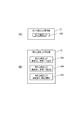
図2は、ガンマ補正LUT保存部12および色むら補正LUT保存部15の説明図であり、図2(A)はガンマ補正LUT保存部12がLUTを記憶した状態を模式的に示し、図2(B)は色むら補正LUT保存部15がLUTを記憶した状態を模式的に示す。
ガンマ補正LUT保存部12には、ガンマ補正LUT12Aが記憶される。ガンマ補正LUT12Aは、変調部32が備える液晶ライトバルブの色特性に合わせて、投射画像Pの色が、本来の画像データD1の表示色となるように補正するためのデータを含む。ガンマ補正LUT保存部12は、図2(A)に示すように少なくとも1つのガンマ補正LUT12Aを記憶する。ガンマ補正実行部13は、ガンマ補正LUT12Aを用いて、画像補正部11から入力された画像データの多階調化や再割り当ての処理を行う。
2 is an explanatory diagram of the gamma correction
The gamma correction
図2(B)に示すように、色むら補正LUT保存部15には、複数の色むら補正LUTを記憶する。図2(B)の例では色むら補正LUT保存部15に3つの色むら補正LUT15A〜15Cが記憶される。
本実施形態の色むら補正LUT15Aは、光源31が定格(輝度100%)、すなわち減光をしないで発光する場合に使用されるLUTである。色むら補正LUT15Aは色均一性を高めることを優先して補正するデータを含み、補正により投射画像Pの明るさが低下することがある。
色むら補正LUT15Bは、光源31が定格より低い輝度で発光する場合、すなわち減光する場合に使用されるLUTである。色むら補正LUT15Bは、色均一性を高めることを優先して補正するデータを含み、補正により投射画像Pの明るさが低下することがある。しかしながら、投射画像Pの中央部と周縁部との色の差が小さく色均一性が高い上に、投射画像Pの色が基準の色に近づけられ、再現性が高められる。光源31の輝度を定格より低くした場合、液晶ライトバルブの特性により、輝度100%の場合との投射画像Pの色差を生じることがあるが、色むら補正LUT15Bは、このような色の差を補正する。このため、例えば省電力化を目的として光源31の輝度を低下させた場合の、色再現性の低下を防止できる。
As shown in FIG. 2B, the color unevenness correction
The color
The color unevenness correction LUT 15B is an LUT used when the
色むら補正LUT15Cは、光源31が定格より低い輝度で発光する場合、すなわち減光する場合に使用されるLUTであり、明るさをできるだけ低下させないように色均一性を高めるよう補正するデータを含む。色むら補正実行部14が色むら補正LUT15Cを用いて補正を行うと、投射画像Pの色均一性、および、色再現性は許容できる範囲内となる。言い換えれば、色むら補正実行部14は、許容できる範囲内で投射画像Pの色むら、および、色再現性の低下を許容し、かつ、補正による投射画像Pの明るさの低下を抑えるように、補正を行う。
The color
図3は、色むら補正LUT保存部15が記憶する色むら補正LUTの説明図である。
図3はL*u*v*表色系における色域を示し、L*軸を縦軸、u*v*軸を横軸としている。図3中央の縦軸はグレイ軸に相当し、この軸上の色は無彩色すなわち黒、グレイおよび白を含む。
図3には光源31の輝度を100%とした場合の投射画像Pの色域(色再現域)を実線で示す。色域C1は投射画像Pの中央における色域であり、色域C2は投射画像Pの周縁部における色域である。また、図3には光源31の輝度を低輝度(例えば、80%)とした場合の投射画像Pの色域を破線で示す。色域C11は投射画像Pの中央における色域であり、色域C12は投射画像Pの周縁部における色域である。これらの色域C1、C2、C11、C12はいずれも説明のための例であって本発明を限定するものではない。
FIG. 3 is an explanatory diagram of the color unevenness correction LUT stored in the color unevenness correction
FIG. 3 shows a color gamut in the L * u * v * color system, where the L * axis is the vertical axis and the u * v * axis is the horizontal axis. The vertical axis in the center of FIG. 3 corresponds to the gray axis, and the colors on this axis include achromatic colors, ie, black, gray, and white.
In FIG. 3, the color gamut (color reproduction gamut) of the projected image P when the luminance of the
まず、光源31の減光をしない場合の投射画像Pの中央部の色について説明する。色域C1内で、L*軸に重なり、かつ最も明るい色は、点CP1の色である。この色が、色域C1で白色に最も近い色となる。また、投射画像Pの周縁部の色は、光源31の減光をしない場合に、色域C2内の色となる。色域C1に比べて色域C2は小さく、明るさが低い。色域C2で白色に最も近い色は、色域C2内でL*軸に重なりかつ最も明るい色、すなわち点CP2の色である。
色むら補正LUT15Aは、投射画像Pの中央部については、白色に相当する階調値(例えば8ビットの階調値(R,G,B)=(256,256,256))の色の目標値をCP1の色に設定し、投射画像Pの周縁部については、白色に相当する階調値の色の目標値をCP2の色に設定して、求められたLUTである。色むら補正LUT15Aを用いれば、光源31の輝度100%の場合の投射画像Pの中央部の白色は、点CP1の色か、これとほぼ同じ色に補正される。また、投射画像Pを構成するフレームの周縁部の白色は、点CP2の色か、これとほぼ同じ色に補正される。
First, the color at the center of the projection image P when the
The color
光源31の減光をする場合の投射画像Pの中央部の色は、色域C11内で選択される。色域C11内でL*軸に重なりかつ最も明るい色は、点CP11の色である。また、光源31の減光をする場合の投射画像Pの周縁部の色は色域C12内で選択され、色域C12内でL*軸に重なりかつ最も明るい色は、点CP12の色である。色むら補正LUT15Bは、投射画像Pの中央部については、白色に相当する階調値の色の目標値をCP11の色に設定し、投射画像Pの周縁部については、白色に相当する階調値の色の目標値をCP12の色に設定して、求められたLUTである。色むら補正LUT15Bを用いれば、光源31を減光した場合の投射画像Pの中央部の白色は、点CP11の色か、これとほぼ同じ色に補正される。また、投射画像Pを構成するフレームの周縁部の白色は、点CP12の色か、これとほぼ同じ色に補正される。
色むら補正LUT15Bは、色域C11、C12のいずれに対しても白色をL*軸上の色とするので、色再現性に優れた補正を可能とし、投射画像Pの中央部と周縁部の色の差もない。その一方で、色域C1、C2の白色に比べてL*軸上の位置が下方にシフトしており、明るさの低下が小さいとはいえない。従って、色むら補正LUT15Bは、明るさの低下を許容し、色均一性を優先した補正が可能なLUTといえる。
The color at the center of the projection image P when the
The color unevenness correction LUT 15B uses white as the color on the L * axis for both of the color gamuts C11 and C12, so that correction with excellent color reproducibility is possible, and the central portion and the peripheral portion of the projected image P can be corrected. There is no color difference. On the other hand, the position on the L * axis is shifted downward as compared with the white colors of the color gamuts C1 and C2, and it cannot be said that the decrease in brightness is small. Therefore, the color unevenness correction LUT 15B can be said to be a LUT that allows a reduction in brightness and can be corrected with priority on color uniformity.
ここで、白色がグレイ軸(L*軸)から離れることを許容すれば、点CP11、CP12より明るい色を目標値にすることができる。例えば、L*軸から許容範囲E1の点を目標値とする場合、色域C11で最も明るい色は点CP21である。このCP21の色を目標値とすれば、投射画像Pの色を、より明るい色に補正できる。点CP21はL*軸上の点ではないから、CP21の色は厳密には無彩色とはいえないが、予め設定された範囲E1の中であれば、人間の視覚により、ほぼ無彩色と知覚され、違和感を生じない。従って、CP21の色を目標値として作成された色むら補正LUT15Cを用いれば、投射画像Pの中央部の色を、違和感なく明るい色に補正できる。
投射画像Pの周縁部についても、L*軸から離れた色を目標値とすることで、より明るい色に補正できる。周縁部の色については、中央部の目標値(ここではCP21)基準として、予め設定された許容範囲E2で最も明るい色を、目標値とする。許容範囲E2は投射画像Pの色均一性を許容する範囲として予め設定される。
このように、CP21、CP22を目標値として作成された色むら補正LUT15Cを用いれば、投射画像Pの色再現性および色均一性を高める補正を、明るさの低下を抑えながら実行できる。色均一性については色むら補正LUT15Bを用いる方が優れているが、図3のCP11とCP21の明るさの差、および、CP12とCP22の明るさの差から、色むら補正LUT15Cを用いれば明るさの低下を抑制できることが明らかである。
許容範囲E1およびE2の具体的な値は、光源31の輝度に対応して複数設定されることが好ましい。光源31の輝度によって、人間が知覚する白色の色ずれの程度が異なるためである。
Here, if white is allowed to be separated from the gray axis (L * axis), a color brighter than the points CP11 and CP12 can be set as the target value. For example, when the target value is a point within the allowable range E1 from the L * axis, the brightest color in the color gamut C11 is the point CP21. If the color of this CP21 is set as a target value, the color of the projection image P can be corrected to a brighter color. Since the point CP21 is not a point on the L * axis, the color of the CP21 is not strictly an achromatic color, but within the preset range E1, it is almost perceived as an achromatic color by human vision. It does not cause a sense of incongruity. Therefore, if the color
The peripheral edge of the projection image P can also be corrected to a brighter color by setting the color away from the L * axis as the target value. As for the color of the peripheral portion, the brightest color in the preset allowable range E2 is set as the target value based on the target value (here, CP21) in the central portion. The allowable range E2 is set in advance as a range that allows the color uniformity of the projection image P.
As described above, by using the color
A plurality of specific values of the allowable ranges E1 and E2 are preferably set corresponding to the luminance of the
このように、色むら補正LUT保存部15は、光源31の輝度に応じて複数の色むら補正LUT15A〜15Cを記憶する。また、色むら補正LUT保存部15は、投射画像Pの色均一性を優先する補正と明るさを優先する補正との各々に対応して、複数の色むら補正LUT15B、15Cを記憶する。そして、これらの色むら補正LUTを切り替えて用いることにより、色むら補正実行部14は、ユーザーの要求やプロジェクター1の設置環境等に対応して、適切な補正を行い、高品位の表示を実現できる。
As described above, the color unevenness correction
ガンマ補正LUT保存部12および色むら補正LUT保存部15がSRAM等を用いた揮発性の記憶装置で構成される場合、ガンマ補正LUT12Aおよび色むら補正LUT15A〜15Cを不揮発的に記憶するLUT記憶部を、画像処理部10に設けてもよい。この場合、プロジェクター1の電源がオンにされた後、LUT記憶部(図示略)からガンマ補正LUT12Aがガンマ補正LUT保存部12にロードされ、色むら補正LUT15A〜15Cが色むら補正LUT保存部15にロードされる。
When the gamma correction
図1に示すように、色むら補正LUT保存部15には、色むら補正LUT選択部16が接続されている。色むら補正LUT選択部16は、色むら補正LUT保存部15に記憶された複数の色むら補正LUT15A〜15Cのうち、色むら補正実行部14が使用する色むら補正LUTを選択する。色むら補正LUT選択部16により選択された色むら補正LUTが、色むら補正LUT保存部15から色むら補正実行部14に出力され、補正に利用される。
As shown in FIG. 1, the color unevenness correction
色むら補正LUT選択部16には、光源輝度決定部17が出力するデータD5が入力される。光源輝度決定部17は、光源31を発光させる輝度を決定する処理を行い、決定した輝度を示す画像データD1を出力する。色むら補正LUT選択部16は、光源輝度決定部17が決定した光源31の輝度に基づき、LUTを選択する。
光源輝度決定部17には、ユーザーの入力操作を受け付ける操作部21、および、プロジェクター1またはスクリーンSCの設置場所における明るさを検出するセンサー22が接続されている。操作部21は、スイッチを備えた操作パネルやリモコン装置(図示略)の信号を受信する赤外線受光部として構成できる。また、センサー22は、例えばプロジェクター1の筐体に設けられた照度センサーである。操作部21が検出したユーザーの操作を示す信号、および、センサー22の検出値が、光源輝度決定部17に入力される。光源輝度決定部17は、ユーザーの操作やセンサー22の検出値、および、画像供給装置2から入力される画像データD1に基づき、光源31の輝度を決定できる。例えば、ユーザーが光源31の輝度を直接指定した場合は、この指定に従って輝度を決定する。また、例えば、画像データD1が暗い映像のデータである場合や、センサー22が検出した周囲の明るさが暗い場合には、光源31の輝度を減光する。光源輝度決定部17が決定した光源31の輝度はデータD5として色むら補正LUT選択部16、および、光源制御部34に出力される。
Data D5 output from the light source luminance determination unit 17 is input to the color unevenness correction
Connected to the light source luminance determination unit 17 are an
ガンマ補正LUT12Aおよび色むら補正LUT15A〜15Cは、画像調整装置4により作成される。
画像調整装置4は、スクリーンSC上の投射画像Pの色を検出する面測定装置3に接続される。画像調整装置4は、面測定装置3が出力するデータD11に基づいて処理を行うガンマ補正目標演算部41、色むら補正目標演算部43、ガンマ補正LUT作成部45および色むら補正LUT作成部47を備える。
The
The image adjusting device 4 is connected to the surface measuring device 3 that detects the color of the projected image P on the screen SC. The image adjustment device 4 includes a gamma correction
面測定装置3および画像調整装置4は、例えばプロジェクター1の出荷前の工程において設置され、プロジェクター1に接続される。
面測定装置3は、CCDやCMOS等からなるイメージセンサーを備え、プロジェクター1が投射する投射画像Pを撮影し、撮影画像データからX,Y,Z三刺激値の面内二次元分布画像データを生成する。面測定装置3は、生成した面内二次元分布画像データから投射画像Pの画面内の位置毎の色特性(VT特性)を示すデータD11を生成し、画像調整装置4に出力する。
The surface measurement device 3 and the image adjustment device 4 are installed, for example, in a process before shipment of the
The surface measuring device 3 includes an image sensor composed of a CCD, a CMOS, or the like, captures a projection image P projected by the
面測定装置3が投射画像Pを撮影する場合、プロジェクター1には画像供給装置2としてコンピューターが接続され、このコンピューターが、面測定用のパターン画像のデータを画像データD1として出力する。このパターン画像は、RGB各単色の全面均一画像(ラスター画像)であり、測定する階調数分、表示される。画像供給装置2としてのコンピューターはパターン画像をソフトウェアにより生成し、或いは予め用意されたパターン画像を読み出して出力する。また、面測定装置3を、画像供給装置2としてのコンピューターが制御して、パターン画像の表示と面測定装置3による撮影とを同期させてもよい。また、パターン画像をプロジェクター1が投射する場合の光源31の輝度を、画像供給装置2としてのコンピューターが制御してもよい。
When the surface measurement device 3 captures the projection image P, a computer is connected to the
ガンマ補正目標演算部41は、目標色空間(例えば、sRGB)と、データD11に含まれる色特性とに基づいて、ガンマ補正LUT12Aを作成する際のターゲットXYZ値を求める。
色むら補正目標演算部43は、図1に示したように、面測定装置3から入力されるデータD11に含まれる色特性のデータに基づき、色むら補正のターゲットXYZ値を求める。色むら補正目標演算部43は、光源31の輝度と、色均一性を優先するか明るさを優先するかに応じて、それぞれ、ターゲットXYZ値を求める。例えば、光源31を減光しない場合の色むら補正LUT15Aを作成する場合、色均一性を優先する色むら補正LUT15Bを作成する場合、および、明るさを優先する色むら補正LUT15Cを作成する場合の各々についてターゲットXYZ値を求める。
The gamma correction
As shown in FIG. 1 , the color unevenness correction
ガンマ補正LUT作成部45は、ガンマ補正目標演算部41が求めたターゲットXYZ値に基づいてガンマ補正LUT12Aを作成する。ガンマ補正LUT作成部45が行う具体的な処理は、例えば、上述した特許文献1に記載された公知の方法を用いることができる。
色むら補正LUT作成部47は、色むら補正目標演算部43により求めたターゲットXYZ値に基づいて、色むら補正LUT15A〜15Cを作成する。色むら補正LUT作成部47が行う具体的な処理は、例えば、上述した特許文献1に記載された公知の方法を用いることができる。
The gamma correction
The color unevenness correction
画像調整装置4は、ガンマ補正LUT作成部45が作成したガンマ補正LUT12Aを、データD13としてガンマ補正LUT保存部12に出力し、ガンマ補正LUT保存部12に記憶させる。また、画像調整装置4は、色むら補正LUT作成部47が作成した色むら補正LUT15A〜15Cを、データD15として色むら補正LUT保存部15に出力し、色むら補正LUT保存部15に記憶させる。これにより、プロジェクター1が変調部32の特性に対応して画像データを補正することができ、色再現性および色均一性の向上を図ることができる。また、プロジェクター1の出荷前に、個々のプロジェクター1に対して画像調整装置4がLUTを作成することで、プロジェクター1の個体差に対応したLUTを作成し、全てのプロジェクター1の色再現性および色均一性の向上を図ることができる。
The image adjustment apparatus 4 outputs the
図1には面測定装置3および画像調整装置4がプロジェクター1の外部装置として接続された構成を例示したが、プロジェクター1が、面測定装置3および画像調整装置4を備えた構成とすることもできる。この場合、面測定装置3はスクリーンSC上の投射画像Pを撮影できればよく、プロジェクター1が台形歪み補正用に撮像部(図示略)を備えていれば、これを用いることができる。また、画像処理部10を構成するCPU等のプロセッサーが、ソフトウェアを実行することにより、画像調整装置4の各部の機能を実現できる。さらに、画像供給装置2がプロジェクター1に出力するパターン画像を画像処理部10が記憶していてもよい。この場合、プロジェクター1が単独で、ガンマ補正LUT12Aおよび色むら補正LUT15A〜15Cを作成できる。この場合、プロジェクター1の個体ごとの色特性に対応した補正を行うことが可能な上、プロジェクター1が設置された後であってもLUTを作成できる。このため、プロジェクター1が備える光源31の発光特性や変調部32の色特性の経時的変化に対応して、最適なガンマ補正LUT12A、色むら補正LUT15A〜15Cを用いて画像データを補正できる。また、光源31を交換した場合にも、光源31の発光特性の変化に対応したLUTを作成できるという利点がある。
Although FIG. 1 illustrates a configuration in which the surface measuring device 3 and the image adjusting device 4 are connected as external devices of the
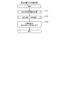
図4は、プロジェクター1の動作を示すフローチャートであり、より詳細には、色むら補正LUT保存部15に記憶された色むら補正LUT15A〜15Cを選択するLUT選択処理を示す。
プロジェクター1は、投射を開始する際、或いは投射中に、図4のLUT選択処理を実行する。例えば、プロジェクター1の電源投入時、画像供給装置2から画像データD1が入力された時、操作部21の操作により投射開始が指示されたときに、LUT選択処理を実行する。また、プロジェクター1は、投射画像Pを投射している間に、予め設定された時間が経過する毎に、LUT選択処理を実行してもよい。
FIG. 4 is a flowchart showing the operation of the
The
画像処理部10は、まず、光源輝度決定部17の機能により、操作部21の操作や事前の設定によって光源31の輝度が100%に指定されているか否かを判定する(ステップS11)。操作部21の操作は、例えば、プロジェクター1の設定メニュー画面を利用した設定操作である。
光源の輝度が100%に指定されている場合(ステップS11;Yes)、色むら補正LUT選択部16は、輝度100%に対応する色むら補正LUT15Aを選択し、色むら補正LUT保存部15から色むら補正実行部14に出力させる(ステップS12)。
First, the
When the luminance of the light source is specified as 100% (step S11; Yes), the color unevenness correction
一方、光源の輝度が100%に指定されていない場合(ステップS11;No)、画像処理部10は、操作部21の操作や事前の設定によって、色均一性を優先する補正を行うよう指定されているか否かを判定する(ステップS13)。色均一性を優先する補正を行うよう指定された場合(ステップS13;Yes)、色むら補正LUT選択部16は、色均一性を優先する色むら補正LUT15Bを選択し、色むら補正LUT保存部15から色むら補正実行部14に出力させる(ステップS14)。
On the other hand, when the luminance of the light source is not designated as 100% (step S11; No), the
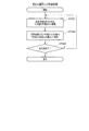
色均一性を優先する補正を行うよう指定されていない場合(ステップS13;No)、画像処理部10は、光源輝度決定部17により画像データD1を解析する(ステップS15)。ここで、画像処理部10は、画像データD1にグレイ軸の色(無彩色)およびグレイ軸に近い色が多いか否かを判定する(ステップS16)。ステップS16では、例えば、1フレームの各画素のRGB階調値に基づき、無彩色および無彩色に近い色の画素の割合を、予め設定された閾値と比較することで判定が行われる。
グレイ軸の色(無彩色)およびグレイ軸に近い色が多い場合(ステップS16;Yes)、画像処理部10は後述するステップS22に移行する。
When it is not designated to perform correction giving priority to color uniformity (step S13; No), the
When there are many gray axis colors (achromatic colors) and many colors close to the gray axis (step S16; Yes), the
また、グレイ軸の色(無彩色)およびグレイ軸に近い色が多くない場合(ステップS16;No)、画像処理部10は、センサー22の検出値を取得する(ステップS17)。センサー22の検出値は、プロジェクター1の設置場所の明るさの指標となる。画像処理部10は、センサー22の検出値から得られる周辺光量が、予め設定された値以上か否かを判定する(ステップS18)。周辺光量が設定値以上の場合(ステップS18;Yes)、画像処理部10は後述するステップS22に移行する。また、周辺光量が設定値未満の場合(ステップS18;No)、画像処理部10は、スクリーンSCにおける投射画像Pのサイズを取得する(ステップS19)。投射画像Pのサイズは、操作部21の操作により設定された設定内容、投射光学系33の状態に基づき取得できる。また、プロジェクター1が台形歪み補正用にスクリーンSCを撮影する撮像部(図示略)を備えている場合、この撮像部を用いて投射画像Pのサイズを検出できる。画像処理部10は、投射画像Pのサイズが設定値以上か否かを判定し(ステップS20)、設定値以上の場合は(ステップS20;Yes)、後述するステップS22に移行する。
Further, when there are not many gray axis colors (achromatic colors) and colors close to the gray axis (step S16; No), the
投射画像Pのサイズが設定値未満の場合(ステップS20;No)、画像処理部10は、色むら補正LUT選択部16により、色むら補正LUT15Aを選択し(ステップS21)、本処理を終了する。
また、ステップS22で、画像処理部10は、光源輝度決定部17の機能により光源31の輝度を定格より低輝度にして、色むら補正LUT選択部16により色むら補正LUT15Cを選択し、本処理を終了する。
When the size of the projection image P is less than the set value (step S20; No), the
In step S22, the
このLUT選択処理により、光源31の輝度が100%に指定されている場合には、この指定が優先され、輝度100%に対応した色むら補正LUT15Aが選択される。また、光源31の輝度が指定されていない場合には、光源31を減光させることも可能である。この場合、フレーム内に無彩色が多い場合、周辺光量が多い場合、および、投射画像Pのサイズが大きい場合には、光源31を減光させた上で、明るさを優先する色むら補正LUT15Cが選択される。これらの場合には、投射画像Pの明るさが低下しても、投射画像Pを見る人にとって違和感が生じにくい。さらに、明るさを優先する色むら補正LUT15Cを用いることで、投射画像Pの明るさを低下させないように画像を補正できるので、より違和感のないように、光源31の輝度を低下させて、例えば省電力化を図ることができる。
When the luminance of the
なお、本発明のプロジェクター1は、図4に示した処理の全てを実行するものに限定されず、一部のみを実行してもよい。すなわち、ステップS11〜S12の動作、および、ステップS13〜S14の動作は、いずれか一方を実行してもよいし、両方とも実行しない構成としてもよい。また、ステップS15〜S16の判定、ステップS17〜S18の判定、および、ステップS19〜S20の判定は、少なくとも1つを実行すればよい。また、これらの判定を全て省略して、ステップS11〜S12の動作、および、ステップS13〜S14の動作のいずれか又は両方を実行してもよい。
Note that the
図5〜図10は、画像調整装置4によりガンマ補正LUT12Aおよび色むら補正LUT15A〜15Cを作成する処理を示すフローチャートである。これらの図を参照して、LUTの作成処理について説明する。
まず、図5に示すように、面測定装置3による色特性測定処理が実行される(ステップST1)。ステップST1の色特性測定処理の詳細は図6に示す通りであり、まず、プロジェクター1によって各階調のラスター画像が投射画像Pとして表示(投射)される(ステップST11)。面測定装置3は、投射画像Pとして投射されたラスター画像を撮影して、撮影画像データからX,Y,Z三刺激値の面内二次元分布画像データを生成する。面測定装置3は、生成した面内二次元分布画像データから、その階調の色特性(VT特性)を示すデータD11を生成し、画像調整装置4に出力する(ステップST12)。面測定装置3は、予め設定された全ての階調値についてステップST11〜ST12の処理を繰り返し実行し(ステップST13)、全階調値について処理が済むと、図5のステップST2に戻る。
5 to 10 are flowcharts showing processing for creating the
First, as shown in FIG. 5, color characteristic measurement processing by the surface measuring device 3 is executed (step ST1). Details of the color characteristic measurement processing in step ST1 are as shown in FIG. 6, and first, a raster image of each gradation is displayed (projected) by the
ここで、面測定装置3が生成した色特性のデータD11に基づき、画像調整装置4によって、ガンマ補正LUT12Aが作成される(ステップST2)。
ステップST2のガンマ補正LUT作成処理の詳細は図7に示す通りであり、まず、ガンマ補正目標演算部41により各階調のターゲットXYZ値が設定される(ステップST21)。続いて、ガンマ補正LUT作成部45により、ガンマ補正目標演算部41が設定したガンマ補正目標値(ターゲットXYZ値)に基づきマトリクス演算が繰り返し実行され、黒(最小階調値)〜白(最大階調値)間の各階調値を実現する入力RGB値が求められる。この演算が全階調について実行され(ステップST23)、ガンマ補正LUT12Aが作成される。作成されたガンマ補正LUT12Aは画像調整装置4からプロジェクター1に出力され、ガンマ補正LUT保存部12に保存され(ステップS24)、図5のステップST3の動作に戻る。
Here, the
The details of the gamma correction LUT creation process in step ST2 are as shown in FIG. 7, and first, the target XYZ value of each gradation is set by the gamma correction target calculation unit 41 (step ST21). Subsequently, the matrix calculation is repeatedly performed by the gamma correction
次に、プロジェクター1が、光源輝度決定部17の機能により、光源31の輝度を、作成するLUTに対応する輝度に調整する(ステップST3)。輝度100%に対応するLUTを作成する場合には、実際に光源31の輝度を100%に調整する。ステップST3の動作は、画像供給装置2、面測定装置3、画像調整装置4或いは他の装置がプロジェクター1を制御して実行させる。
その後、面測定装置3が、図6に示したステップST11〜ST13の処理を再び実行し、光源31の輝度を調整した後の色特性を生成する(ステップST4)。
Next, the
Thereafter, the surface measuring device 3 executes the processes of steps ST11 to ST13 shown in FIG. 6 again to generate the color characteristics after adjusting the luminance of the light source 31 (step ST4).
面測定装置3が生成した色特性のデータD11に基づき、画像調整装置4が、色むら補正LUT15A〜15Cを作成する色むら補正LUT作成処理を実行する(ステップS5)。この色むら補正LUT作成処理は図8を参照して後述する。
プロジェクター1、画像供給装置2、面測定装置3および画像調整装置4を制御する装置は、ステップST1〜ST5の処理を、設定された全ての光源31の輝度について実行したか否かを判定する(ステップST6)。例えば、光源31の輝度を段階的に設定可能な場合、各段階についてステップST1〜ST5の処理が実行されたか否かを判定し、処理が済んだ場合にはLUT作成処理が完了する。
Based on the color characteristic data D11 generated by the surface measuring device 3, the image adjustment device 4 executes color unevenness correction LUT creation processing for creating the color
The apparatus that controls the
図8には、ステップST5(図5)で実行される色むら補正LUT作成処理を詳細に示す。まず、色むら補正目標演算部43により、色むら補正LUTを作成するための目標値が算出される(ステップST51)。ステップST51の処理の詳細は図9に示す通りである。色むら補正目標演算部43は、フレームの中央部における目標白色点を算出する(ステップST511)。
ステップST511で、色むら補正目標演算部43は、輝度100%の場合に対応した色むら補正LUT15Aには、図3の色域C1内かつグレイ軸L*上で最も明るい点を目標白色点として設定する。また、色均一性を優先する色むら補正LUT15Bを作成する場合、色域C11内かつグレイ軸L*上で最も明るい点を目標白色点として設定する。
また、色むら補正目標演算部43は、明るさ優先の色むら補正LUT15Cを作成する場合、色域C11内かつグレイ軸L*上で最も明るい点を目標白色点として設定した後、目標白色点を色域C11内かつ許容範囲E1内で移動させる。そして、色域C11内でより明るい点があれば、その点を目標白色点に再設定する。
FIG. 8 shows the color unevenness correction LUT creation process executed in step ST5 (FIG. 5) in detail. First, the target value for creating the color unevenness correction LUT is calculated by the color unevenness correction target calculation unit 43 (step ST51). Details of the processing in step ST51 are as shown in FIG. The uneven color correction
In step ST511, the color unevenness correction
Further, when creating the
次に、色むら補正目標演算部43は、フレームの周縁部における目標白色点を算出する(ステップST512)。ステップST512で、色むら補正目標演算部43は、輝度100%の場合に対応した色むら補正LUT15Aには、図3の色域C2内かつグレイ軸L*上で最も明るい点を目標白色点として設定する。また、色均一性を優先する色むら補正LUT15Bを作成する場合、色域C12内かつグレイ軸L*上で最も明るい点を目標白色点として設定する。
また、色むら補正目標演算部43は、明るさ優先の色むら補正LUT15Cを作成する場合、色域C12内かつグレイ軸L*上で最も明るい点を目標白色点として設定した後、目標白色点を色域C12内かつ許容範囲E2内で移動させる。そして、色域C12内でより明るい点があれば、その点を目標白色点に再設定する。ここで、再設定する目標白色点の明度が、ステップST511で設定したフレーム中央部の目標白色点よりも高い場合、色むら補正目標演算部43は、目標白色点を再度設定する。ここで、色むら補正目標演算部43は、ステップST511で設定した目標白色点と同じ明度で、この目標白色点に近く色域C12内の点を探索し、目標白色点とする。
Next, the uneven color correction
Further, when creating the
ステップST511、およびステップS512で、色むら補正目標演算部43は、求めた目標白色点のXYZ三刺激値を求め、これを目標値とする。
続いて、色むら補正目標演算部43は、ステップST511、ST512で算出した目標白色点をもとに、白色以外の階調についてXYZ目標値を求める(ステップST513)。ステップST513では、ステップST511、ST512で求めた目標白色点から黒を示す点すなわちグレイ軸の下端に至る曲線(図3中の符号G)を描くように、各階調の目標値を定める。この処理の後、画像調整装置4はステップST52(図8)に戻る。
In step ST511 and step S512, the color unevenness correction
Subsequently, the uneven color correction
続いて、色むら補正LUT作成部47により、色むら補正LUTが作成される(ステップST52)。ステップST52の処理の詳細は図10に示す通りである。色むら補正LUT作成部47は、色むら補正目標演算部43により求めたターゲットXYZ値に基づきマトリクス演算を実行し、ターゲットXYZ値を実現する入力RGB値を探索する(ステップST521)。色むら補正LUT作成部47は、探索した結果と、図7のガンマ補正LUT作成処理でガンマ補正LUT作成部45が作成したガンマ補正LUT12Aとの差分を求めて、差分を色むら補正LUTとして保存する(ステップS522)。色むら補正LUT作成部47は、全ての階調についてステップST521、ST522の処理を実行し、色むら補正LUTを作成する(ステップST523)。
その後、画像調整装置4はステップST53(図8)に戻り、色むら補正LUT作成部47により作成された色むら補正LUTは画像調整装置4からプロジェクター1に出力され、色むら補正LUT保存部15に保存される(ステップST53)。
Subsequently, the color unevenness correction
Thereafter, the image adjustment device 4 returns to step ST53 (FIG. 8), and the color unevenness correction LUT created by the color unevenness correction
以上説明したように、本発明を適用した実施形態に係るプロジェクター1は、光源31を有する画像形成部30および画像処理部10を備える。画像形成部30は、入力される画像データD1に基づいて投射画像Pを表示する。画像処理部10は、画像データを補正データに基づいて補正する。ここで、画像処理部10は、補正データとして、色むら補正LUT15B(第1の補正データ)と、色むら補正LUT15C(第2の補正データ)とを切り替えて、変調部32が描画する色を補正する。色むら補正LUT15Bは、投射画像Pの表示色を基準色に合わせる補正を可能とするLUTであり、色むら補正LUT15Cは、投射画像Pの表示色を基準色から予め設定された許容範囲内の色にする補正を可能とするLUTである。
このため、色むら補正LUT15Aや色むら補正LUT15Bを用いて、投射画像Pの表示色を基準色に合わせる補正をして高い色再現性や色均一性を実現できる。また、色むら補正LUT15Cを用いて、色を基準色から許容範囲内の色にする補正を行うことができる。色むら補正LUT15Cを利用する場合、例えば明るさの低下を抑えることを優先して表示色を補正できる。この場合、色を基準色から許容範囲内に補正するので色再現性や色均一性が低下する心配はない。従って、色再現性や色均一性を優先した表示色の補正と、明るさの低下を抑制することを優先した表示色の補正とを行うことが可能となる。また、これらの補正を切り替えて行うことにより、例えばユーザーの要求に応じて明るさや色再現性を優先することができ、利便性を高めることができる。
As described above, the
Therefore, high color reproducibility and color uniformity can be realized by correcting the display color of the projection image P to the reference color using the color
また、画像形成部30は、画像データに基づいて光源31が発する光を変調して画像光L2を発する変調部32を備える。プロジェクター1は、スクリーンSCに投射する画像光の光量を制御する光量制御手段として、光源制御部34を備える。光源制御部34は、光源31を定格で発光させる通常状態と定格より低輝度で発光させる減光状態とを切り替えて、光源31を発光させる。光源制御部34が光源31を減光状態にすると、画像光の光量が低下した状態となる。画像処理部10は、減光状態において、色むら補正LUT15Bと、投射画像Pの輝度を優先して投射画像Pの表示色を基準色から予め設定された許容範囲内の色にする補正を可能とする色むら補正LUT15Cとを切り替えて補正を行う。このため、投射画像Pを構成する画像光の光量を低下させた場合に、投射画像Pの明るさの低下を抑えて表示色を補正できる。
Further, the
また、色むら補正LUT15Bは、光源31を減光状態で発光させる場合の投射画像Pの白色を無彩色に合わせる補正を可能とするデータを含む。色むら補正LUT15Cは、光源31を減光状態で発光させる場合の投射画像Pの白色を、L*u*v*色空間において無彩色を示す座標から許容範囲E1内の色にする補正を可能とするデータを含む。このため、投射画像Pの白色を無彩色にして高い色再現性を実現する補正、及び、例えば投射画像Pの明るさの低下を抑えるように、投射画像Pの白色を違和感のない程度に補正することができる。
In addition, the color unevenness correction LUT 15B includes data that enables correction to match the white color of the projected image P with an achromatic color when the
また、画像処理部10は、画像形成部30が画像データに基づいて描画する画像のガンマ補正を行うガンマ補正LUT12Aと、投射画像Pの面内の色むらを補正する色むら補正LUT15A〜15Cとを有する。このため、投射画像Pの色再現性を高めることができ、かつ、軽負荷の処理によって色むらを補正して、高品位の表示を実現できる。
The
また、画像処理部10は、光源制御部34が光源31を発光させる輝度に対応して、複数の色むら補正LUT15Bと、複数の色むら補正LUT15Cとを記憶していてもよく、この場合、光源31の輝度に対応する色むら補正LUTを選択してもよい。この場合、様々な光源31の輝度の変化に対応して、色再現性や色均一性の高い表示を実現できる。
In addition, the
なお、上述した実施形態は本発明を適用した具体的態様の例に過ぎず、本発明を限定するものではなく、上記実施形態とは異なる態様として本発明を適用することも可能である。例えば、投射光学系33から発する画像光の光量を制御する光量制御手段として、光L1を減光させる減光部を設けてもよい。減光部の具体的な構成としては、例えば、光源31と変調部32との間の光路で光を遮る遮光板を、この遮光板を動かして光L1の光量を調整する駆動部を設けることができる。また、光量制御手段として、光源31と変調部32との間の光路に光L1を透過させるフィルターを設け、このフィルターの透過率を変化させる手段を設けてもよい。また、この種のフィルターを、変調部32と投射光学系33との間の光路や投射光学系33の内部に設けることもできる。このような構成を用いれば、光源31の発光輝度を変化させなくても、スクリーンSCに投射される画像光の光量を制御できる。
The above-described embodiment is merely an example of a specific mode to which the present invention is applied, and the present invention is not limited. The present invention can be applied as a mode different from the above-described embodiment. For example, as a light amount control means for controlling the light amount of the image light emitted from the projection
また、上記実施形態では、プロジェクター1において、変調部32の液晶ライトバルブの色特性に起因する投射画像Pの色ずれ、色むらを防止するため、画像データを補正する構成を例示して説明した。本発明はこれに限定されず、光源が発した光により画像を表示する表示装置において、表示画像の色ずれ、色むらを防止するために画像データを補正する全ての場合に適用可能である。
また、図1に示したプロジェクター1および周辺装置の各機能部は機能的構成を示すものであって、具体的な実装形態は特に制限されない。つまり、必ずしも各機能部に個別に対応するハードウェアが実装される必要はなく、一つのプロセッサーがプログラムを実行することで複数の機能部の機能を実現する構成とすることも勿論可能である。また、上記実施形態においてソフトウェアで実現されている機能の一部をハードウェアで実現してもよく、あるいは、ハードウェアで実現されている機能の一部をソフトウェアで実現してもよい。その他の他の各部の具体的な細部構成についても、本発明の趣旨を逸脱しない範囲で任意に変更可能である。
Further, in the above-described embodiment, the
Further, each functional unit of the
1…プロジェクター(表示装置)、2…画像供給装置、3…面測定装置、4…画像調整装置、10…画像処理部(画像補正手段)、11…画像補正部、12…ガンマ補正LUT保存部、12A…ガンマ補正LUT、13…ガンマ補正実行部、14…色むら補正実行部、15…色むら補正LUT保存部、15A〜15C…色むら補正LUT(第1の補正データ、第2の補正データ)、16…色むら補正LUT選択部、17…光源輝度決定部、21…操作部、22…センサー、30…画像形成部(表示手段)、31…光源、32…変調部(変調手段)、33…投射光学系(投射手段)、34…光源制御部(光源制御手段)、35…表示制御部、41…ガンマ補正目標演算部、43…色むら補正目標演算部、45…ガンマ補正LUT作成部、47…色むら補正LUT作成部、P…投射画像、SC…スクリーン。
DESCRIPTION OF
Claims (8)
前記画像データを補正データに基づいて補正する画像補正手段と、を備え、
前記画像補正手段は、前記表示画像の表示色を基準色に合わせる補正を可能とする第1の補正データと、前記表示画像の表示色を前記基準色から予め設定された許容範囲内の色にする補正を可能とする第2の補正データとを切り替えて、前記表示画像の表示色を補正し、
前記表示手段は、前記画像データに基づいて前記光源が発する光を変調して画像光を生成する変調手段を備え、前記画像光により前記表示画像を表示し、
前記画像光の光量を制御する光量制御手段を備え、
前記画像補正手段は、前記光量制御手段により前記画像光の光量を低下させる場合に、前記第1の補正データと、前記表示画像の輝度を優先して前記表示画像の表示色を前記基準色から予め設定された許容範囲内の色にする補正を可能とする前記第2の補正データとを切り替えて、前記表示画像の表示色を補正し、
前記第1の補正データは、前記画像光の光量を低下させる場合の前記表示画像の白色を無彩色に合わせる補正を可能とするデータを含み、
前記第2の補正データは、前記画像光の光量を低下させる場合の前記表示画像の白色を、L * u * v * 色空間において無彩色を示す座標から前記許容範囲内の色にする補正を可能とするデータを含むこと、
を特徴とする表示装置。 Display means comprising a light source and displaying a display image based on the image data;
Image correction means for correcting the image data based on the correction data,
The image correction means includes first correction data that enables correction to match the display color of the display image with a reference color, and sets the display color of the display image to a color within a preset allowable range from the reference color. Switching the second correction data that enables correction to be performed, correcting the display color of the display image ,
The display means includes modulation means for generating image light by modulating light emitted from the light source based on the image data, and displays the display image with the image light.
A light amount control means for controlling the light amount of the image light;
The image correction means prioritizes the first correction data and the brightness of the display image from the reference color when the light quantity control means reduces the light quantity of the image light. Switching between the second correction data that enables correction to a color within a preset allowable range, correcting the display color of the display image,
The first correction data includes data that enables correction to adjust the white color of the display image to an achromatic color when the light amount of the image light is reduced,
The second correction data is a correction in which the white color of the display image when the light amount of the image light is reduced is changed from a coordinate indicating an achromatic color in an L * u * v * color space to a color within the allowable range. Including data to enable ,
A display device.
前記画像データを補正データに基づいて補正する画像補正手段と、を備え、Image correction means for correcting the image data based on the correction data,
前記画像補正手段は、前記表示画像の表示色を基準色に合わせる補正を可能とする第1の補正データと、前記表示画像の表示色を前記基準色から予め設定された許容範囲内の色にする補正を可能とする第2の補正データとを切り替えて、前記表示画像の表示色を補正し、The image correction means includes first correction data that enables correction to match the display color of the display image with a reference color, and sets the display color of the display image to a color within a preset allowable range from the reference color. Switching the second correction data that enables correction to be performed, correcting the display color of the display image,
前記表示手段は、前記画像データに基づいて前記光源が発する光を変調して画像光を生成する変調手段を備え、前記画像光により前記表示画像を表示し、The display means includes modulation means for generating image light by modulating light emitted from the light source based on the image data, and displays the display image with the image light.
前記画像光の光量を制御する光量制御手段を備え、A light amount control means for controlling the light amount of the image light;
前記画像補正手段は、前記光量制御手段により前記画像光の光量を低下させる場合に、前記第1の補正データと、前記表示画像の輝度を優先して前記表示画像の表示色を前記基準色から予め設定された許容範囲内の色にする補正を可能とする前記第2の補正データとを切り替えて、前記表示画像の表示色を補正し、The image correction means prioritizes the first correction data and the brightness of the display image from the reference color when the light quantity control means reduces the light quantity of the image light. Switching between the second correction data that enables correction to a color within a preset allowable range, correcting the display color of the display image,
前記第1の補正データおよび前記第2の補正データは、前記表示画像の面内の色むらを補正する色むら補正LUTであり、The first correction data and the second correction data are color unevenness correction LUTs for correcting color unevenness in the surface of the display image,
前記画像補正手段は、前記表示手段が画像データに基づいて描画する画像のガンマ補正を行うガンマ補正LUTと、前記色むら補正LUTとを用いて前記画像を補正すること、The image correcting unit corrects the image using a gamma correction LUT for performing gamma correction of an image drawn by the display unit based on image data, and the color unevenness correction LUT;
を特徴とする表示装置。A display device.
前記画像データを補正データに基づいて補正する画像補正手段と、を備え、Image correction means for correcting the image data based on the correction data,
前記画像補正手段は、前記表示画像の表示色を基準色に合わせる補正を可能とする第1の補正データと、前記表示画像の表示色を前記基準色から予め設定された許容範囲内の色にする補正を可能とする第2の補正データとを切り替えて、前記表示画像の表示色を補正し、The image correction means includes first correction data that enables correction to match the display color of the display image with a reference color, and sets the display color of the display image to a color within a preset allowable range from the reference color. Switching the second correction data that enables correction to be performed, correcting the display color of the display image,
前記表示手段は、前記画像データに基づいて前記光源が発する光を変調して画像光を生成する変調手段を備え、前記画像光により前記表示画像を表示し、The display means includes modulation means for generating image light by modulating light emitted from the light source based on the image data, and displays the display image with the image light.
前記画像光の光量を制御する光量制御手段を備え、A light amount control means for controlling the light amount of the image light;
前記画像補正手段は、前記光量制御手段により前記画像光の光量を低下させる場合に、前記第1の補正データと、前記表示画像の輝度を優先して前記表示画像の表示色を前記基準色から予め設定された許容範囲内の色にする補正を可能とする前記第2の補正データとを切り替えて、前記表示画像の表示色を補正し、The image correction means prioritizes the first correction data and the brightness of the display image from the reference color when the light quantity control means reduces the light quantity of the image light. Switching between the second correction data that enables correction to a color within a preset allowable range, correcting the display color of the display image,
前記画像補正手段は、前記画像光の光量に対応する複数の前記第1の補正データ、および、複数の前記第2の補正データを切り替えて、前記表示画像の表示色を補正すること、The image correction means switches the plurality of first correction data corresponding to the light amount of the image light and the plurality of second correction data to correct the display color of the display image;
を特徴とする表示装置。A display device.
前記画像データを補正データに基づいて補正する画像補正手段と、を備え、Image correction means for correcting the image data based on the correction data,
前記画像補正手段は、前記表示画像の表示色を基準色に合わせる補正を可能とする第1の補正データと、前記表示画像の表示色を前記基準色から予め設定された許容範囲内の色にする補正を可能とする第2の補正データとを切り替えて、前記表示画像の表示色を補正し、The image correction means includes first correction data that enables correction to match the display color of the display image with a reference color, and sets the display color of the display image to a color within a preset allowable range from the reference color. Switching the second correction data that enables correction to be performed, correcting the display color of the display image,
前記表示手段は、前記画像データに基づいて前記光源が発する光を変調して画像光を生成する変調手段を備え、前記画像光により前記表示画像を表示し、The display means includes modulation means for generating image light by modulating light emitted from the light source based on the image data, and displays the display image with the image light.
前記画像光の光量を制御する光量制御手段を備え、A light amount control means for controlling the light amount of the image light;
前記画像補正手段は、前記光量制御手段により前記画像光の光量を低下させる場合に、前記第1の補正データと、前記表示画像の輝度を優先して前記表示画像の表示色を前記基準色から予め設定された許容範囲内の色にする補正を可能とする前記第2の補正データとを切り替えて、前記表示画像の表示色を補正し、The image correction means prioritizes the first correction data and the brightness of the display image from the reference color when the light quantity control means reduces the light quantity of the image light. Switching between the second correction data that enables correction to a color within a preset allowable range, correcting the display color of the display image,
前記光量制御手段により前記画像光の光量を低下させた場合の前記表示画像の表示色に基づいて、少なくとも前記第2の補正データを生成する補正データ生成手段を備えたこと、Correction data generation means for generating at least the second correction data based on the display color of the display image when the light quantity of the image light is reduced by the light quantity control means;
を特徴とする表示装置。A display device.
前記表示画像の表示色を補正データに基づいて補正する画像補正処理を行い、
前記画像補正処理において、前記表示画像の表示色を基準色に合わせる補正を可能とする第1の補正データと、前記表示画像の表示色を前記基準色から予め設定された許容範囲内の色にする補正を可能とする第2の補正データとを切り替えて補正を行い、
前記画像データに基づいて前記光源が発する光を変調して画像光を生成する変調手段を備え、前記画像光により前記表示画像を表示し、
前記画像光の光量を制御する光量制御手段を備え、
前記画像補正処理において、前記光量制御手段により前記画像光の光量を低下させる場合に、前記第1の補正データと、前記表示画像の輝度を優先して前記表示画像の表示色を前記基準色から予め設定された許容範囲内の色にする補正を可能とする前記第2の補正データとを切り替えて、前記表示画像の表示色を補正し、
前記第1の補正データは、前記画像光の光量を低下させる場合の前記表示画像の白色を無彩色に合わせる補正を可能とするデータを含み、
前記第2の補正データは、前記画像光の光量を低下させる場合の前記表示画像の白色を、L * u * v * 色空間において無彩色を示す座標から前記許容範囲内の色にする補正を可能とするデータを含むこと、
を特徴とする表示装置の制御方法。 In a control method for controlling a display device that includes a light source and displays a display image based on image data,
Performing image correction processing for correcting the display color of the display image based on correction data;
In the image correction process, first correction data that enables correction to match the display color of the display image with a reference color, and the display color of the display image to a color within a preset allowable range from the reference color There line correction by switching between the second correction data that enables correction for,
Modulation means for generating image light by modulating light emitted from the light source based on the image data, displaying the display image by the image light;
A light amount control means for controlling the light amount of the image light;
In the image correction process, when the light amount of the image light is reduced by the light amount control means, the display color of the display image is changed from the reference color with priority given to the luminance of the first correction data and the display image. Switching between the second correction data that enables correction to a color within a preset allowable range, correcting the display color of the display image,
The first correction data includes data that enables correction to adjust the white color of the display image to an achromatic color when the light amount of the image light is reduced,
The second correction data is a correction in which the white color of the display image when the light amount of the image light is reduced is changed from a coordinate indicating an achromatic color in an L * u * v * color space to a color within the allowable range. Including data to enable ,
A control method of a display device characterized by the above.
前記表示画像の表示色を補正データに基づいて補正する画像補正処理を行い、Performing image correction processing for correcting the display color of the display image based on correction data;
前記画像補正処理において、前記表示画像の表示色を基準色に合わせる補正を可能とする第1の補正データと、前記表示画像の表示色を前記基準色から予め設定された許容範囲内の色にする補正を可能とする第2の補正データとを切り替えて補正を行い、In the image correction process, first correction data that enables correction to match the display color of the display image with a reference color, and the display color of the display image to a color within a preset allowable range from the reference color The correction is performed by switching the second correction data that enables the correction to be performed,
前記画像データに基づいて前記光源が発する光を変調して画像光を生成する変調手段を備え、前記画像光により前記表示画像を表示し、Modulation means for generating image light by modulating light emitted from the light source based on the image data, displaying the display image by the image light;
前記画像光の光量を制御する光量制御手段を備え、A light amount control means for controlling the light amount of the image light;
前記画像補正処理において、前記光量制御手段により前記画像光の光量を低下させる場合に、前記第1の補正データと、前記表示画像の輝度を優先して前記表示画像の表示色を前記基準色から予め設定された許容範囲内の色にする補正を可能とする前記第2の補正データとを切り替えて、前記表示画像の表示色を補正し、In the image correction process, when the light amount of the image light is reduced by the light amount control means, the display color of the display image is changed from the reference color with priority given to the luminance of the first correction data and the display image. Switching between the second correction data that enables correction to a color within a preset allowable range, correcting the display color of the display image,
前記第1の補正データおよび前記第2の補正データは、前記表示画像の面内の色むらを補正する色むら補正LUTであり、The first correction data and the second correction data are color unevenness correction LUTs for correcting color unevenness in the surface of the display image,
前記画像補正処理において、前記画像データに基づいて描画する画像のガンマ補正を行うガンマ補正LUTと、前記色むら補正LUTとを用いて前記画像を補正すること、Correcting the image using a gamma correction LUT for performing gamma correction of an image to be drawn based on the image data and the color unevenness correction LUT in the image correction process;
を特徴とする表示装置の制御方法。A control method of a display device characterized by the above.
前記表示画像の表示色を補正データに基づいて補正する画像補正処理を行い、Performing image correction processing for correcting the display color of the display image based on correction data;
前記画像補正処理において、前記表示画像の表示色を基準色に合わせる補正を可能とする第1の補正データと、前記表示画像の表示色を前記基準色から予め設定された許容範囲内の色にする補正を可能とする第2の補正データとを切り替えて補正を行い、In the image correction process, first correction data that enables correction to match the display color of the display image with a reference color, and the display color of the display image to a color within a preset allowable range from the reference color The correction is performed by switching the second correction data that enables the correction to be performed,
前記画像データに基づいて前記光源が発する光を変調して画像光を生成する変調手段を備え、前記画像光により前記表示画像を表示し、Modulation means for generating image light by modulating light emitted from the light source based on the image data, displaying the display image by the image light;
前記画像光の光量を制御する光量制御手段を備え、A light amount control means for controlling the light amount of the image light;
前記画像補正処理において、前記光量制御手段により前記画像光の光量を低下させる場合に、前記第1の補正データと、前記表示画像の輝度を優先して前記表示画像の表示色を前記基準色から予め設定された許容範囲内の色にする補正を可能とする前記第2の補正データとを切り替えて、前記表示画像の表示色を補正し、In the image correction process, when the light amount of the image light is reduced by the light amount control means, the display color of the display image is changed from the reference color with priority given to the luminance of the first correction data and the display image. Switching between the second correction data that enables correction to a color within a preset allowable range, correcting the display color of the display image,
前記画像補正処理において、前記画像光の光量に対応する複数の前記第1の補正データ、および、複数の前記第2の補正データを切り替えて、前記表示画像の表示色を補正すること、In the image correction process, the display color of the display image is corrected by switching between the plurality of first correction data and the plurality of second correction data corresponding to the light amount of the image light.
を特徴とする表示装置の制御方法。A control method of a display device characterized by the above.
前記表示画像の表示色を補正データに基づいて補正する画像補正処理を行い、Performing image correction processing for correcting the display color of the display image based on correction data;
前記画像補正処理において、前記表示画像の表示色を基準色に合わせる補正を可能とする第1の補正データと、前記表示画像の表示色を前記基準色から予め設定された許容範囲内の色にする補正を可能とする第2の補正データとを切り替えて補正を行い、In the image correction process, first correction data that enables correction to match the display color of the display image with a reference color, and the display color of the display image to a color within a preset allowable range from the reference color The correction is performed by switching the second correction data that enables the correction to be performed,
前記画像データに基づいて前記光源が発する光を変調して画像光を生成する変調手段を備え、前記画像光により前記表示画像を表示し、Modulation means for generating image light by modulating light emitted from the light source based on the image data, displaying the display image by the image light;
前記画像光の光量を制御する光量制御手段を備え、A light amount control means for controlling the light amount of the image light;
前記画像補正処理において、前記光量制御手段により前記画像光の光量を低下させる場合に、前記第1の補正データと、前記表示画像の輝度を優先して前記表示画像の表示色を前記基準色から予め設定された許容範囲内の色にする補正を可能とする前記第2の補正データとを切り替えて、前記表示画像の表示色を補正し、In the image correction process, when the light amount of the image light is reduced by the light amount control means, the display color of the display image is changed from the reference color with priority given to the luminance of the first correction data and the display image. Switching between the second correction data that enables correction to a color within a preset allowable range, correcting the display color of the display image,
前記光量制御手段により前記画像光の光量を低下させた場合の前記表示画像の表示色に基づいて、少なくとも前記第2の補正データを生成すること、Generating at least the second correction data based on the display color of the display image when the light amount of the image light is reduced by the light amount control means;
を特徴とする表示装置の制御方法。A control method of a display device characterized by the above.
Priority Applications (3)
| Application Number | Priority Date | Filing Date | Title |
|---|---|---|---|
| JP2013231918A JP6331340B2 (en) | 2013-11-08 | 2013-11-08 | Display device and control method of display device |
| US14/532,598 US10002587B2 (en) | 2013-11-08 | 2014-11-04 | Display apparatus and method for controlling display apparatus |
| CN201410643380.0A CN104637457B (en) | 2013-11-08 | 2014-11-06 | The control method of display device and display device |
Applications Claiming Priority (1)
| Application Number | Priority Date | Filing Date | Title |
|---|---|---|---|
| JP2013231918A JP6331340B2 (en) | 2013-11-08 | 2013-11-08 | Display device and control method of display device |
Publications (3)
| Publication Number | Publication Date |
|---|---|
| JP2015094767A JP2015094767A (en) | 2015-05-18 |
| JP2015094767A5 JP2015094767A5 (en) | 2016-12-08 |
| JP6331340B2 true JP6331340B2 (en) | 2018-05-30 |
Family
ID=53043436
Family Applications (1)
| Application Number | Title | Priority Date | Filing Date |
|---|---|---|---|
| JP2013231918A Expired - Fee Related JP6331340B2 (en) | 2013-11-08 | 2013-11-08 | Display device and control method of display device |
Country Status (3)
| Country | Link |
|---|---|
| US (1) | US10002587B2 (en) |
| JP (1) | JP6331340B2 (en) |
| CN (1) | CN104637457B (en) |
Families Citing this family (12)
| Publication number | Priority date | Publication date | Assignee | Title |
|---|---|---|---|---|
| US10217438B2 (en) * | 2014-05-30 | 2019-02-26 | Apple Inc. | User interface and method for directly setting display white point |
| CN104766585B (en) * | 2015-04-29 | 2017-08-25 | 深圳市华星光电技术有限公司 | The method of the grey decision-making of pixel during setting liquid crystal panel imaging |
| KR102368596B1 (en) * | 2015-06-26 | 2022-03-03 | 삼성디스플레이 주식회사 | Image processing apparatus and image processing method |
| KR20170038967A (en) * | 2015-09-30 | 2017-04-10 | 삼성디스플레이 주식회사 | Display panel driving apparatus, method of driving display panel using the same and display apparatus having the same |
| US20170374331A1 (en) * | 2016-06-27 | 2017-12-28 | Intel Corporation | Auto keystone correction and auto focus adjustment |
| CN109937444B (en) * | 2016-11-15 | 2021-08-31 | 夏普株式会社 | Display device |
| US10750148B2 (en) * | 2016-12-19 | 2020-08-18 | Iix Inc. | Unevenness correction system, unevenness correction apparatus and panel drive circuit |
| CN109429045B (en) * | 2017-08-30 | 2021-11-09 | 深圳光峰科技股份有限公司 | Image processing apparatus, image display apparatus, image processing method, and image display method |
| US11302234B2 (en) | 2018-08-07 | 2022-04-12 | Facebook Technologies, Llc | Error correction for display device |
| US10847075B1 (en) * | 2019-04-10 | 2020-11-24 | Facebook Technologies, Llc | Error correction for display device |
| US20230344970A1 (en) * | 2020-01-30 | 2023-10-26 | Dolby Laboratories Licensing Corporation | Projection system and method for uniformity correction |
| KR102397201B1 (en) * | 2020-09-16 | 2022-05-12 | 엘지전자 주식회사 | A display device and method of the same |
Family Cites Families (13)
| Publication number | Priority date | Publication date | Assignee | Title |
|---|---|---|---|---|
| JP2000330504A (en) * | 1999-05-18 | 2000-11-30 | Toshiba Corp | Video display device |
| JP2002204374A (en) * | 2000-10-23 | 2002-07-19 | Seiko Epson Corp | Creation method for color correction table, apparatus for image processing, method therefor and recording medium |
| JP4065517B2 (en) * | 2002-11-27 | 2008-03-26 | キヤノン株式会社 | Color difference determination apparatus and method |
| JP2004184852A (en) * | 2002-12-05 | 2004-07-02 | Olympus Corp | Display device, light source device and illuminator |
| JP2006113151A (en) | 2004-10-12 | 2006-04-27 | Seiko Epson Corp | Image quality adjusting method of display device, image quality adjusting device and display device |
| JP4810249B2 (en) | 2006-02-15 | 2011-11-09 | Necディスプレイソリューションズ株式会社 | Image display device and luminance range correction method |
| US7796144B2 (en) * | 2006-05-30 | 2010-09-14 | Himax Technologies Limited | Gamma correction device of display apparatus and method thereof |
| JP4222392B2 (en) | 2006-08-04 | 2009-02-12 | セイコーエプソン株式会社 | Image display device and image display method |
| JP2008209796A (en) | 2007-02-27 | 2008-09-11 | Seiko Epson Corp | Projection system, projector, and image information processor |
| JP2009092983A (en) * | 2007-10-10 | 2009-04-30 | Seiko Epson Corp | Image processing device, image processing method and program |
| JP5381363B2 (en) * | 2008-09-01 | 2014-01-08 | セイコーエプソン株式会社 | projector |
| JP2010127994A (en) * | 2008-11-25 | 2010-06-10 | Sony Corp | Method of calculating correction value, and display device |
| US8648868B2 (en) * | 2010-01-06 | 2014-02-11 | Apple Inc. | Color correction to facilitate switching between graphics-processing units |
-
2013
- 2013-11-08 JP JP2013231918A patent/JP6331340B2/en not_active Expired - Fee Related
-
2014
- 2014-11-04 US US14/532,598 patent/US10002587B2/en active Active
- 2014-11-06 CN CN201410643380.0A patent/CN104637457B/en active Active
Also Published As
| Publication number | Publication date |
|---|---|
| US10002587B2 (en) | 2018-06-19 |
| US20150130827A1 (en) | 2015-05-14 |
| CN104637457A (en) | 2015-05-20 |
| JP2015094767A (en) | 2015-05-18 |
| CN104637457B (en) | 2019-03-08 |
Similar Documents
| Publication | Publication Date | Title |
|---|---|---|
| JP6331340B2 (en) | Display device and control method of display device | |
| JP5320865B2 (en) | Projector and projector control method | |
| US10681319B2 (en) | Image projection system, projector, and method for controlling image projection system | |
| JP4210863B2 (en) | Image processing system, display device, program, and information storage medium | |
| JP4341597B2 (en) | Gamma curve adjustment device and adjustment point setting method | |
| EP1391870B1 (en) | Image display system, projector, information storage medium and image processing method | |
| JP7338404B2 (en) | Display system control method and control device | |
| US9583068B2 (en) | Image display apparatus and method of controlling image display apparatus | |
| JP4810944B2 (en) | Luminance unevenness and / or color unevenness correction data calculation method, brightness unevenness and / or color unevenness correction method, and display device | |
| WO2016157670A1 (en) | Image display device, image display method, information processing device, information processing method, and program | |
| JP2015018051A (en) | Image projection device and image display system | |
| JP2010010754A (en) | Display device | |
| US20190320148A1 (en) | Projection apparatus, control method, and non-transitory storage medium | |
| JP2006251445A (en) | Projector, image display method and image display program | |
| JP6035718B2 (en) | Projection apparatus, projection method, and program | |
| JP2016186556A (en) | Image display device and control method for image display device | |
| JP2016109840A (en) | Display device and method for controlling display device | |
| JP4591618B2 (en) | Gamma curve adjustment device and minimum increase / decrease setting method | |
| JP2016149047A (en) | Image processing apparatus, display device, and image processing method | |
| JP2016156911A (en) | Image processing apparatus, display device, and control method of image processing apparatus | |
| JP2019041189A (en) | Image projection apparatus and control method of the same | |
| JP2019201271A (en) | Projection type display device | |
| JP2019028130A (en) | Display device and display device control program | |
| JP2016109841A (en) | Display device and method for controlling display device | |
| JP2024008045A (en) | Control device, projection device, projection system, control method, and program |
Legal Events
| Date | Code | Title | Description |
|---|---|---|---|
| RD04 | Notification of resignation of power of attorney |
Free format text: JAPANESE INTERMEDIATE CODE: A7424 Effective date: 20160617 |
|
| RD03 | Notification of appointment of power of attorney |
Free format text: JAPANESE INTERMEDIATE CODE: A7423 Effective date: 20160627 |
|
| A521 | Request for written amendment filed |
Free format text: JAPANESE INTERMEDIATE CODE: A523 Effective date: 20161020 |
|
| A621 | Written request for application examination |
Free format text: JAPANESE INTERMEDIATE CODE: A621 Effective date: 20161020 |
|
| A977 | Report on retrieval |
Free format text: JAPANESE INTERMEDIATE CODE: A971007 Effective date: 20170731 |
|
| A131 | Notification of reasons for refusal |
Free format text: JAPANESE INTERMEDIATE CODE: A131 Effective date: 20170905 |
|
| A521 | Request for written amendment filed |
Free format text: JAPANESE INTERMEDIATE CODE: A523 Effective date: 20171101 |
|
| TRDD | Decision of grant or rejection written | ||
| A01 | Written decision to grant a patent or to grant a registration (utility model) |
Free format text: JAPANESE INTERMEDIATE CODE: A01 Effective date: 20180403 |
|
| A61 | First payment of annual fees (during grant procedure) |
Free format text: JAPANESE INTERMEDIATE CODE: A61 Effective date: 20180416 |
|
| R150 | Certificate of patent or registration of utility model |
Ref document number: 6331340 Country of ref document: JP Free format text: JAPANESE INTERMEDIATE CODE: R150 |
|
| LAPS | Cancellation because of no payment of annual fees |