JP6327802B2 - Radiation generating tube, radiation generating apparatus and radiation imaging system using the same - Google Patents
Radiation generating tube, radiation generating apparatus and radiation imaging system using the same Download PDFInfo
- Publication number
- JP6327802B2 JP6327802B2 JP2013123299A JP2013123299A JP6327802B2 JP 6327802 B2 JP6327802 B2 JP 6327802B2 JP 2013123299 A JP2013123299 A JP 2013123299A JP 2013123299 A JP2013123299 A JP 2013123299A JP 6327802 B2 JP6327802 B2 JP 6327802B2
- Authority
- JP
- Japan
- Prior art keywords
- tube
- radiation
- insulating
- insulating tube
- cathode
- Prior art date
- Legal status (The legal status is an assumption and is not a legal conclusion. Google has not performed a legal analysis and makes no representation as to the accuracy of the status listed.)
- Active
Links
Images


Classifications
-
- H—ELECTRICITY
- H01—ELECTRIC ELEMENTS
- H01J—ELECTRIC DISCHARGE TUBES OR DISCHARGE LAMPS
- H01J35/00—X-ray tubes
- H01J35/02—Details
- H01J35/16—Vessels; Containers; Shields associated therewith
-
- H—ELECTRICITY
- H01—ELECTRIC ELEMENTS
- H01J—ELECTRIC DISCHARGE TUBES OR DISCHARGE LAMPS
- H01J19/00—Details of vacuum tubes of the types covered by group H01J21/00
- H01J19/42—Mounting, supporting, spacing, or insulating of electrodes or of electrode assemblies
-
- H—ELECTRICITY
- H01—ELECTRIC ELEMENTS
- H01J—ELECTRIC DISCHARGE TUBES OR DISCHARGE LAMPS
- H01J35/00—X-ray tubes
- H01J35/02—Details
- H01J35/04—Electrodes ; Mutual position thereof; Constructional adaptations therefor
- H01J35/08—Anodes; Anti cathodes
-
- H—ELECTRICITY
- H01—ELECTRIC ELEMENTS
- H01J—ELECTRIC DISCHARGE TUBES OR DISCHARGE LAMPS
- H01J35/00—X-ray tubes
- H01J35/02—Details
- H01J35/04—Electrodes ; Mutual position thereof; Constructional adaptations therefor
- H01J35/08—Anodes; Anti cathodes
- H01J35/112—Non-rotating anodes
- H01J35/116—Transmissive anodes
-
- H—ELECTRICITY
- H01—ELECTRIC ELEMENTS
- H01J—ELECTRIC DISCHARGE TUBES OR DISCHARGE LAMPS
- H01J37/00—Discharge tubes with provision for introducing objects or material to be exposed to the discharge, e.g. for the purpose of examination or processing thereof
- H01J37/02—Details
- H01J37/16—Vessels; Containers
-
- G—PHYSICS
- G21—NUCLEAR PHYSICS; NUCLEAR ENGINEERING
- G21G—CONVERSION OF CHEMICAL ELEMENTS; RADIOACTIVE SOURCES
- G21G4/00—Radioactive sources
- G21G4/04—Radioactive sources other than neutron sources
- G21G4/06—Radioactive sources other than neutron sources characterised by constructional features
- G21G4/08—Radioactive sources other than neutron sources characterised by constructional features specially adapted for medical application
-
- H—ELECTRICITY
- H01—ELECTRIC ELEMENTS
- H01J—ELECTRIC DISCHARGE TUBES OR DISCHARGE LAMPS
- H01J19/00—Details of vacuum tubes of the types covered by group H01J21/00
- H01J19/54—Vessels; Containers; Shields associated therewith
- H01J19/56—Vessels; Containers; Shields associated therewith characterised by the material of the vessel or container
-
- H—ELECTRICITY
- H01—ELECTRIC ELEMENTS
- H01J—ELECTRIC DISCHARGE TUBES OR DISCHARGE LAMPS
- H01J2229/00—Details of cathode ray tubes or electron beam tubes
- H01J2229/48—Electron guns
- H01J2229/4824—Constructional arrangements of electrodes
- H01J2229/4827—Electrodes formed on surface of common cylindrical support
-
- H—ELECTRICITY
- H01—ELECTRIC ELEMENTS
- H01J—ELECTRIC DISCHARGE TUBES OR DISCHARGE LAMPS
- H01J2229/00—Details of cathode ray tubes or electron beam tubes
- H01J2229/86—Vessels and containers
-
- H—ELECTRICITY
- H01—ELECTRIC ELEMENTS
- H01J—ELECTRIC DISCHARGE TUBES OR DISCHARGE LAMPS
- H01J2235/00—X-ray tubes
- H01J2235/16—Vessels
-
- H—ELECTRICITY
- H01—ELECTRIC ELEMENTS
- H01J—ELECTRIC DISCHARGE TUBES OR DISCHARGE LAMPS
- H01J2235/00—X-ray tubes
- H01J2235/16—Vessels
- H01J2235/165—Shielding arrangements
-
- H—ELECTRICITY
- H01—ELECTRIC ELEMENTS
- H01J—ELECTRIC DISCHARGE TUBES OR DISCHARGE LAMPS
- H01J2235/00—X-ray tubes
- H01J2235/16—Vessels
- H01J2235/165—Shielding arrangements
- H01J2235/166—Shielding arrangements against electromagnetic radiation
-
- H—ELECTRICITY
- H01—ELECTRIC ELEMENTS
- H01J—ELECTRIC DISCHARGE TUBES OR DISCHARGE LAMPS
- H01J2237/00—Discharge tubes exposing object to beam, e.g. for analysis treatment, etching, imaging
- H01J2237/16—Vessels
-
- H—ELECTRICITY
- H05—ELECTRIC TECHNIQUES NOT OTHERWISE PROVIDED FOR
- H05G—X-RAY TECHNIQUE
- H05G1/00—X-ray apparatus involving X-ray tubes; Circuits therefor
- H05G1/02—Constructional details
- H05G1/04—Mounting the X-ray tube within a closed housing
-
- H—ELECTRICITY
- H05—ELECTRIC TECHNIQUES NOT OTHERWISE PROVIDED FOR
- H05G—X-RAY TECHNIQUE
- H05G1/00—X-ray apparatus involving X-ray tubes; Circuits therefor
- H05G1/02—Constructional details
- H05G1/04—Mounting the X-ray tube within a closed housing
- H05G1/06—X-ray tube and at least part of the power supply apparatus being mounted within the same housing
Landscapes
- Chemical & Material Sciences (AREA)
- Analytical Chemistry (AREA)
- X-Ray Techniques (AREA)
- Physics & Mathematics (AREA)
- Health & Medical Sciences (AREA)
- Life Sciences & Earth Sciences (AREA)
- Biochemistry (AREA)
- General Health & Medical Sciences (AREA)
- General Physics & Mathematics (AREA)
- Immunology (AREA)
- Pathology (AREA)
Description
本発明は、例えば医療機器、非破壊検査装置等に適用できる放射線発生管及びそれを備えた放射線発生装置と放射線撮影システムに関する。 The present invention relates to a radiation generating tube applicable to, for example, a medical device, a nondestructive inspection apparatus, and the like, and a radiation generating apparatus and a radiation imaging system including the same.
一般に、放射線発生装置は、放射線源として、放射線発生管を内蔵している。放射線発生管は、絶縁管の開口の一方に陰極を、他方に陽極を取り付けた真空容器で構成され、陰極には電子放出源が接続され、陽極はターゲットを備えている。放射線発生管は、陰極と陽極との間に高電圧を印加することにより、電子放出源から放出される電子をターゲットに照射し、X線等の放射線を発生させている。 In general, a radiation generating apparatus has a built-in radiation generating tube as a radiation source. The radiation generating tube is composed of a vacuum vessel in which a cathode is attached to one of openings of an insulating tube and an anode is attached to the other. An electron emission source is connected to the cathode, and the anode includes a target. The radiation generating tube irradiates the target with electrons emitted from an electron emission source by applying a high voltage between the cathode and the anode, and generates radiation such as X-rays.
電子放出源を良好に保つためには真空容器を作製する際に部材の接合信頼性を高める必要があり、例えば、特許文献1には、絶縁管の陰極が絶縁管の長手方向と半径方向の両方向において接合された構成が開示されている。
In order to keep the electron emission source good, it is necessary to increase the joining reliability of the members when manufacturing the vacuum container. For example, in
電子放出源から放出された電子線がターゲットに衝突するとターゲットからは放射線が発生するが、ほとんどが熱に変わるため、ターゲットが発熱し、その熱がターゲットを保持している陽極に伝わって陽極の温度が上昇する。 When the electron beam emitted from the electron emission source collides with the target, radiation is generated from the target. However, most of the radiation is converted into heat, so the target generates heat, and the heat is transmitted to the anode holding the target and The temperature rises.
放射線発生装置においては、放射線発生管の高温部を冷却して放射線発生管全体の均熱化を図るため、冷媒として絶縁性流体が充填されているが、陽極の急激な温度上昇に絶縁性流体による均熱化が追いつかない場合があった。具体的には、医療用のX線撮影装置において、循環器等の動きや患者の体の動きに対応して短時間での撮影となる場合など、解像度を高めるために、短パルス・大管電流が必要となり、ターゲットが急激に温度上昇する場合があった。また、産業分野においても、デバイスの高集積化に伴い、検査時の透過像の高解像度化が求められており、そのためには、ターゲットに入射する電子線の焦点を絞った撮影が要求される場合があり、ターゲットが急激に温度上昇する場合があった。 In a radiation generator, an insulating fluid is filled as a refrigerant in order to cool the high temperature part of the radiation generating tube so as to equalize the temperature of the entire radiation generating tube. In some cases, the soaking could not keep up. Specifically, in a medical X-ray imaging apparatus, in order to increase the resolution, such as when imaging is performed in a short time corresponding to the movement of the circulatory organ or the like, or the movement of the patient's body, In some cases, current was required, and the temperature of the target suddenly increased. Also, in the industrial field, with the higher integration of devices, there is a demand for higher resolution of transmitted images at the time of inspection. For this purpose, photographing with a focused electron beam incident on the target is required. In some cases, the temperature of the target suddenly increased.
セラミック等の絶縁体で構成される絶縁管は、線膨張係数が、金属等の導電体で構成される陽極の線膨張係数よりも低い。そのため、陽極及び絶縁管の温度が上昇した場合、この線膨張係数の違いにより熱応力が発生する。係る熱応力は、破壊靭性値が低い絶縁管の陽極との接合部に集中する。さらに、上記したように、陽極が急激に温度上昇した場合には、陽極と絶縁管の温度差が大きくなり、上記線膨張係数の違いによる熱応力がより大きくなり、絶縁管の陽極との接合部において、クラック等のダメージを生じる場合があった。このような絶縁管のダメージは真空容器の真空度を低下させる原因となり、放射線発生装置の信頼性を損なう一因であった。 An insulating tube made of an insulator such as ceramic has a linear expansion coefficient lower than that of an anode made of a conductor such as metal. Therefore, when the temperature of the anode and the insulating tube rises, thermal stress is generated due to the difference in the linear expansion coefficient. Such thermal stress is concentrated at the junction with the anode of the insulating tube having a low fracture toughness value. Furthermore, as described above, when the temperature of the anode suddenly rises, the temperature difference between the anode and the insulating tube increases, the thermal stress due to the difference in the linear expansion coefficient increases, and the insulating tube joins with the anode. In some parts, damage such as cracks may occur. Such damage of the insulating tube is a cause of lowering the vacuum degree of the vacuum vessel, which is one factor that impairs the reliability of the radiation generator.
また、陰極においても、熱陰極型の電子放出源を用いた場合には、該電子放出源が駆動によって発熱し、陰極の温度が急激に上昇して、上記陽極と同様に、絶縁管の陰極との接合部周辺に熱応力が集中して、絶縁管にクラック等のダメージが生じる場合があった。 In addition, when a hot cathode type electron emission source is used for the cathode, the electron emission source generates heat by driving, and the temperature of the cathode rapidly rises. In some cases, thermal stress concentrates on the periphery of the joint portion, causing damage such as cracks in the insulating tube.
本発明の課題は、駆動時のターゲットや電子放出源の発熱による絶縁管のダメージの発生を防止した放射線発生管及び該放射線発生管を備えた放射線発生装置を提供し、高解像度の撮影が可能な放射線撮影システムを提供することにある。 An object of the present invention is to provide a radiation generating tube that prevents damage to an insulating tube due to heat generated by a target and an electron emission source during driving, and a radiation generating device including the radiation generating tube, and can perform high-resolution imaging. Is to provide a simple radiography system.
本発明の第1は、絶縁管と、電子放出源を有し前記絶縁管の管軸方向における一端の側に接合される陰極と、ターゲットを有し前記絶縁管の管軸方向における他端の側に接合される陽極と、を備えた放射線発生管であって、
前記陰極及び前記陽極の一方は、前記陰極及び陽極の他方に向けて管状に突出し前記絶縁管の管内周面または管外周面に接合される管状延出部を備え、
前記絶縁管は、前記管状延出部と接合された部分における管厚よりも管厚が薄い領域を、前記陰極及び前記陽極の前記絶縁管との接合部のそれぞれから前記管軸方向において離間した位置に有し、前記陰極及び前記陽極の他方と前記絶縁管との接合部においては前記領域よりも管厚が厚いことを特徴とする。
また、本発明の第2は、絶縁管と、電子放出源を有し前記絶縁管の管軸方向における一端の側に接合される陰極と、ターゲットを有し前記絶縁管の管軸方向における他端の側に接合される陽極と、を備えた放射線発生管であって、
前記陰極及び前記陽極は、それぞれ、前記陽極及び前記陰極に向けて管状に突出し前記絶縁管の管内周面または管外周面に接合される管状延出部を備え、
前記絶縁管は、前記管状延出部と接合された部分における管厚よりも管厚が薄い領域を、前記陰極及び前記陽極の前記管状延出部との接合部のそれぞれから離間した位置に有していることを特徴とする放射線発生管である。
According to a first aspect of the present invention, an insulating tube, a cathode having an electron emission source and bonded to one end side in the tube axial direction of the insulating tube, and a target having the other end in the tube axial direction of the insulating tube are provided. A radiation generating tube comprising: an anode joined to the side;
The cathode and hand of the anode is provided with the cathode and the tubular extending portion which is joined to the tube circumference or Kangaishu surface of projecting the insulating tube into the tubular toward the other of the anode,
The insulating tube is spaced apart regions tube is thinner than the wall thickness of said tubular extension portion and the joining portion, in the tube axis direction from the respective junction with the insulating tube before Symbol cathode and the anode The tube is thicker than the region at the junction between the other of the cathode and the anode and the insulating tube .
A second aspect of the present invention includes an insulating tube, a cathode having an electron emission source and joined to one end side in the tube axis direction of the insulating tube, and a target having a target in the tube axis direction of the insulating tube. A radiation generating tube having an anode joined to an end side,
Each of the cathode and the anode includes a tubular extending portion that protrudes in a tubular shape toward the anode and the cathode and is joined to a tube inner peripheral surface or a tube outer peripheral surface of the insulating tube,
The insulating tube has a region where the tube thickness is thinner than the tube thickness at the portion joined to the tubular extension portion at a position spaced apart from each of the junction portions of the cathode and the anode with the tubular extension portion. It is the radiation generating tube characterized by having carried out.
本発明の第3は、上記本発明第1または第2の放射線発生管と、前記放射線発生管を収容し、前記放射線発生管から生じる放射線を取り出すための放出窓を有する収納容器と、を備え、前記収納容器の内部の余空間が絶縁性流体で満たされていることを特徴とする放射線発生装置である。 A third aspect of the present invention includes the above-described first or second radiation generating tube of the present invention, and a storage container that houses the radiation generating tube and has a discharge window for taking out radiation generated from the radiation generating tube. The radiation generator is characterized in that the extra space inside the storage container is filled with an insulating fluid.
本発明の第4は、上記本発明第3の放射線発生装置と、
前記放射線発生装置から放出され、被検体を透過した放射線を検出する放射線検出装置と、
前記放射線発生装置と前記放射線検出装置とを連携制御する制御装置とを備えることを特徴とする放射線撮影システム。
A fourth aspect of the present invention is the above-described third radiation generator of the present invention,
A radiation detector that detects radiation emitted from the radiation generator and transmitted through the subject;
A radiation imaging system comprising: a control device that controls the radiation generation device and the radiation detection device in a coordinated manner.
本発明によれば、陽極及び陰極の少なくとも一方に延出部を設けて絶縁管と接合して接合部の強度を高めると同時に、絶縁管の長手方向の中間部に管厚の薄い領域を設けたことにより、上記接合部に集中する熱応力を係る管厚の薄い領域で解消することができる。よって、駆動時に陽極や陰極が急激に温度上昇しても、放射線発生管の絶縁管にクラック等のダメージが発生する恐れがなく、真空容器の真空度を悪化させることなく、長期にわたって駆動が可能な放射線発生装置及び放射線撮影システムが提供される。 According to the present invention, at least one of the anode and the cathode is provided with an extension portion and joined to the insulating tube to increase the strength of the joint portion, and at the same time, a region having a thin tube thickness is provided in the middle portion of the insulating tube in the longitudinal direction. As a result, the thermal stress concentrated on the joint can be eliminated in the thin region of the tube. Therefore, even if the temperature of the anode or cathode suddenly rises during driving, there is no risk of damage such as cracks in the insulation tube of the radiation generating tube, and it can be driven for a long time without deteriorating the vacuum degree of the vacuum vessel A radiation generator and a radiation imaging system are provided.
以下、図面を参照して本発明の放射線発生管、放射線発生装置、放射線撮影システムについて説明する。 Hereinafter, a radiation generating tube, a radiation generating apparatus, and a radiation imaging system of the present invention will be described with reference to the drawings.
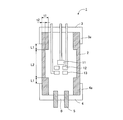
図1に示すように、本発明の放射線発生管1は、絶縁管2の一方の開口を陰極3が、他方の開口を陽極4が覆い、絶縁管2の開口の端面に陰極3及び陽極4の周縁部が接合されて真空容器が構成された透過型の放射線発生管である。陰極3は電子放出源11を備えており、陽極4は透過型のターゲット6を備えている。
As shown in FIG. 1, the
絶縁管2には、アルミナ等のセラミックス材料やガラス等の電気的に絶縁性の材料が用いられる。また、陰極3及び陽極4はNiCuFeMn合金、NiCrFe系合金、FeNiCo合金等の低線膨張係数合金やステンレスなどの金属から形成される。NiCuFeMn合金としては、MONEL(登録商標)が、NiCrFe系合金としてはINCONEL(登録商標)が、FeNiCo合金としてはKOVAR(米国登録商標)がそれぞれ市販されている。
For the
また、本例では陰極3及び陽極4がそれぞれ、絶縁管2の外周に突出する延出部3a、4aを備えており、係る延出部3a、4aと絶縁管2の外周とがそれぞれ接合されている。本発明では陰極3及び陽極4の少なくとも一方に延出部3a,4aを設けて絶縁管2と接合する。
Further, in this example, the
電子放出源11は、真空容器の内部、陽極4に設けたターゲット6に対向して配置されている。本発明ではさらに、図1に示すように引き出し電極12とレンズ電極13を設けても良い。これらを電子放出源11の近傍に設けた場合、引き出し電極12によって形成される電界によって放出された電子は、レンズ電極13で収束され、ターゲット6に入射する。
The
電子放出源11にはタングステンフィラメントや、含浸型カソードのような熱陰極、又はカーボンナノチューブ等の冷陰極を用いることができる。この際に含浸型カソードのような熱陰極型を使用するとヒータの熱により電子放出源11を有する陰極3の温度が上昇する。
The
ターゲット6はそれ自身が電子の照射で放射線を放出する材料で構成しても、放射線を透過する基材にターゲット金属を成膜した構成であってもよい。放射線を透過する基材としては、ターゲット金属を支持できる強度を有し、ターゲット金属で発生した放射線の吸収が少なく、且つターゲット金属で発生した熱をすばやく放熱できるよう熱伝導率の高いものが好ましい。例えばダイヤモンド、炭化シリコン、窒化アルミニウム等を用いることができる。
The
ターゲット金属を構成する材料は、融点が高く、放射線発生効率の高いものが好ましい。例えばタングステン、タンタル、モリブデン等を用いることができる。発生した放射線がターゲット金属を透過する際に生じる吸収を軽減するため、ターゲット金属の厚みは数μm乃至十数μm程度が適当である。 The material constituting the target metal is preferably a material having a high melting point and high radiation generation efficiency. For example, tungsten, tantalum, molybdenum, or the like can be used. In order to reduce absorption generated when the generated radiation passes through the target metal, the thickness of the target metal is suitably about several μm to several tens of μm.
図1の構成例では、ターゲット6を、電子通過路を有する放射線遮蔽体5の該電子通過路内に接合して保持し、該放射線遮蔽体5を陽極4に接合している。放射線遮蔽体5は、不要な放射線を遮蔽するためのものであり、鉛やタングステンを用いることができるが、材料はこれに限定されない。本例では、放射線遮蔽体5を介してターゲット6及び陽極4の電位を制御する。
In the configuration example of FIG. 1, the
ターゲット6と放射線遮蔽体5との接合、放射線遮蔽体5と陽極4との接合、陰極3と絶縁管2との接合、及び陽極4と絶縁管2との接合は真空気密接合である。真空気密接合としては、ろう付け、鋳こみ、ハンダ付け、溶接、レーザー溶接、ネジこみ、焼きバメ、テーパーはめ込み、接着剤による接合手段が用いられる。
The bonding between the
放射線を発生させるために、電子放出源11とターゲット6との間に印加される電圧Vaは、放射線の使用用途によって異なるものの、概ね40kV乃至120kV程度である。電子放出源11から放出された電子線が衝突するとターゲット6からは放射線が発生するが、ほとんどが熱に変わるため、ターゲット6は発熱し、ターゲット6を有する陽極4の温度が上昇する。
In order to generate radiation, the voltage Va applied between the
上記したような陰極3や陽極4の温度上昇は、これらが接合された絶縁管2に伝わり、接合部において絶縁管2に熱応力が発生する。上記したように、絶縁管2は陰極3や陽極4よりも破壊靭性値が低く、急激に陰極3や陽極4の温度が上昇し、熱膨張を生じた場合には、絶縁管2の陰極3や陽極4との接合部に熱応力が集中し、絶縁管2にクラック等のダメージが生じてしまう。図1の構成においては、係る熱応力は主として、絶縁管2の、延伸部3a,4aとの接合部に集中する。
The temperature rise of the
本発明では、この絶縁管2の接合部に集中する熱応力を緩和するために、図1に示すように、絶縁管2の長手方向の中間部に管厚の薄い領域を設けている。このように、延伸部3a,4aが接合された領域の絶縁管2の管厚よりも薄い領域を設けることで、係る領域で絶縁管2の変形が容易になり、係る領域の変形によって熱応力を解消することができる。その結果、絶縁管2の接合部における熱応力の集中を避けることができ、絶縁管2におけるクラックの発生等、ダメージの発生を防止することができる。
In the present invention, in order to relieve the thermal stress concentrated on the joint portion of the insulating
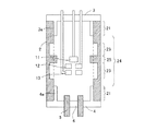
本発明では、少なくとも放射線発生管1の長手方向の中間部において、延伸部3a、4aが接合された領域の絶縁管2の管厚よりも管厚が薄い領域を有していればよい。よって、図2に示すように、絶縁管2の中間部24において、接合領域21の管厚よりも管厚が厚い領域25と薄い領域23とを有している形態も本発明に含まれる。尚、本発明において絶縁管2の長手方向の中間部とは、図2に示すように、絶縁管2の延伸部3a、4aと接合された領域21以外の領域24を言う。本発明においては、図1に示すように、絶縁管2の長手方向の中央部に管厚の薄い領域を設けることが好ましい。
In the present invention, it is only necessary that at least an intermediate portion in the longitudinal direction of the
絶縁管2が変形して応力集中を低減するメカニズムからすれば、絶縁管2全体の厚さが薄い方が変形は容易となるが、陰極3や陽極4との接続箇所は接続信頼性を上げるためには面積が広い方が良く、管厚は厚い方が望ましい。さらに、接合部での絶縁管2の管厚が薄い場合、応力集中に対する破壊耐圧が低下してしまう。よって絶縁管2の管厚が薄くなる領域は、延出部3a,4aの先端より、前記延出部3a,4aと接合された領域の絶縁管2の管厚以上離れている、即ち図1においてはt1<L1であることが好ましい。
If the
また、逆に、絶縁管2の管厚の薄い領域が狭すぎると、熱応力の集中を低減する効果が劣るため、係る領域L2は絶縁管2の長さの40%以上であることが好ましい。
Conversely, if the region where the insulating
さらに、絶縁管2の管厚の薄い領域が薄すぎると強度に劣るため、管厚の薄い領域の管厚t2は、管厚の厚い領域の管厚t1の10%乃至80%であることが好ましい。
Furthermore, since the strength of the insulating
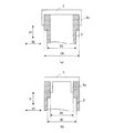
図1に示した実施形態では、陰極3,陽極4と絶縁管2とは、延出部3a,4bが絶縁管2の外周と接合し、且つ、絶縁管2の管厚の薄い領域は、管厚の厚い領域よりも絶縁管2の内周の直径が大きくなっているが、本発明は係る形態に限定されない。図3,図4は陰極3と絶縁管2との接合形態と絶縁管2の断面形状の他の形態を示す断面模式図である。また、図3,図4には陰極3と絶縁管2との接合形態のみを示すが、本発明においては、陽極4と絶縁管2との接合にも係る形態を適用することができる。
In the embodiment shown in FIG. 1, the
図3において、矢印31は絶縁管2の長手方向、即ち、管軸方向であり、矢印32は該長手方向に直交する方向、即ち、絶縁管2が円筒の場合には、直径方向である。本例においては絶縁管2は円筒の場合を例に挙げて説明するが、本発明においては絶縁管2は角筒であっても良い。図3(a)は、絶縁管2の管厚の薄い領域の外周の直径33が、管厚の厚い領域の外周の直径34よりも小さくなる形態である。また、図3(b)は陰極3の延出部3aが陰極3の周縁部よりも内側に形成され、係る延出部3aが絶縁管2の内周と接合されている形態である。また、図3(b)は、絶縁管2の管厚の薄い領域の内周の直径35が、管厚の厚い領域の内周の直径36よりも大きくなる形態である。図4(a)は、絶縁管2の管厚の厚い領域から管厚の薄い領域に向かって、管厚が曲線的に連続して薄くなる形態である。図4(b)は、絶縁管2の管厚の厚い領域から管厚の薄い領域に向かって、管厚が直線的に連続して薄くなる形態である。図4(c)は、図4(a)と同様に、絶縁管2の管厚の厚い領域から管厚の薄い領域に向かって、管厚が曲線的に連続して薄くなる形態であるが、断面において絶縁管2の側面がコーナー部を持たないため、熱応力の集中を緩和する効果が高く、好ましい。
In FIG. 3, the
尚、図3(b)、図4(a)乃至(c)においては、絶縁管2の管厚が薄い領域は、直径方向32における絶縁管2の内周の位置が、管軸方向31において変化する形態としたが、本発明はこれに限定されない。図3(a)のように、直径方向32における絶縁管2の外周の位置が、管軸方向31において変化する形態としてもよく、また、これらを組み合わせた形態としても良い。
3B and 4A to 4C, the region where the tube thickness of the insulating
放射線発生管1は、不図示の排気管を通じて管内を真空に排気した後、該排気管を封止することで、内部を真空にすることができる。このように作製した放射線発生管1の内部には、さらに真空度を高めるために、不図示のゲッターを配置しても良い。
The
次に、本発明の放射線発生管を備える放射線発生装置について説明する。図5は図1の放射線発生管1を備える放射線発生装置の構成の一例を示す断面模式図である。
Next, a radiation generator provided with the radiation generating tube of the present invention will be described. FIG. 5 is a schematic cross-sectional view showing an example of the configuration of a radiation generating apparatus including the
図5の放射線発生装置100は、透過型の放射発生管1を備えており、この放射線発生管1は収納容器50の内部に収容されている。この収納容器50内に放射線発生管1を収容した余剰空間には絶縁性流体51が充填されている。収納容器50の内部には、不図示の回路基板及び絶縁トランス等から構成される駆動回路56を設けても良い。駆動回路56を設けた場合、例えば放射線発生管1に端子55,57,58,59を介して駆動回路56から電圧信号が印加され放射線の発生を制御することができる。
The
収納容器50は、容器としての十分な強度を有していれば良く、金属やプラスチック材料等から構成される。収納容器50には、放射線を透過し収納容器50の外部に放射線を取り出すための放出窓52が設けられている。放射線発生管1から放出された放射線はこの放出窓52を通して外部に放出される。放出窓52には、ガラス、アルミニウム、ベリリウム等が用いられる。
The
絶縁性流体51は、電気絶縁性を有していれば良く、液体でも気体でも良い。例えば絶縁媒体及び放射線発生管1の冷却効果を重視すれば、冷却媒体としての役割を有する電気絶縁油を用いるのが好ましい。電気絶縁油としては、鉱油、シリコーン油、フッ素系電気絶縁性液体等が好適に用いられる。一方、軽量、小型化を重視するならば、気体を用いた方が絶縁性液体よりも装置を軽くすることができる。気体では空気や六フッ化硫黄等が用いられ、六フッ化硫黄がより好適に用いられる。
The insulating
次に、図6に基づいて、本発明に係る放射線撮影システムの一実施形態を説明する。 Next, an embodiment of a radiation imaging system according to the present invention will be described with reference to FIG.
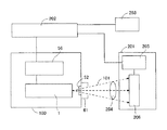
図6に示すように、本発明の放射線発生装置200は、その放射線放出窓52部分に設けられた可動絞りユニット61を備えている。可動絞りユニット61は、放射線発生装置100から照射される放射線101の照射野の広さを調整する機能を有する。また、可動絞りユニット61として、放射線の照射野を可視光により模擬表示できる機能が付加されたものを用いることもできる。
As shown in FIG. 6, the radiation generating apparatus 200 of the present invention includes a
システム制御装置202は、放射線発生装置100と放射線検出装置201とを連携制御する。駆動回路56は、システム制御装置202による制御の下に、放射線発生管1に各種の制御信号を出力する。この制御信号により、放射線発生装置100から放出される放射線101の放出状態が制御される。放射線発生装置100から放出された放射線101は、被検体204を透過して検出器206で検出される。検出器206は、検出した放射線を画像信号に変換して信号処理部205に出力する。信号処理部205は、システム制御装置202による制御の下に、画像信号に所定の信号処理を施し、処理された画像信号をシステム制御装置202に出力する。システム制御装置202は、処理された画像信号に基づいて、表示装置203に画像を表示させるための表示信号を表示装置203に出力する。表示装置203は、表示信号に基づく画像を、被検体204の撮影画像としてスクリーンに表示する。
The
放射線の代表例はX線であり、本発明の放射線発生装置と放射線撮影システムは、X線発生装置とX線撮影システムとして利用することができる。X線撮影システムは、工業製品の非破壊検査や人体や動物の病理診断に用いることができる。 A representative example of radiation is X-rays, and the radiation generator and radiography system of the present invention can be used as an X-ray generator and X-ray imaging system. The X-ray imaging system can be used for nondestructive inspection of industrial products and pathological diagnosis of human bodies and animals.
(参考実施例1)
図7(a)に概略構成を示す放射線発生管を備えた、図5に示す放射線発生装置を作製した。
( Reference Example 1)
A radiation generating apparatus shown in FIG. 5 having a radiation generating tube having a schematic configuration shown in FIG.
絶縁管2としては長さが80mm、外周の直径が50mm、管厚の厚い部分の内周の直径が40mm、管厚の薄い部分の内周の直径が44mmのアルミナ製の円筒の絶縁管を用いた。管厚は厚い部分が5mm、薄い部分が3mmである。絶縁管2の管厚の厚い部分は一方の開口から他方の開口に向けて11mmの範囲とした。管厚の厚い部分と薄い部分との間には、一方の開口から11mmの位置から他方の開口に向けて23mmの位置までを、図4(b)に示したように管厚が直線的に連続して薄くなるように管厚変化領域として形成した。管厚の厚い部分は、陰極3の延出部3a端部から6mmの位置までである。
As the insulating
陰極3は直径が51.5mm、厚さが3mmの円盤状の周縁から長さ5mm、厚さ0.75mmの管状の延出部3aが突出する形態とした。陽極4は直径が50mm、厚さが8mmの円盤状であり、延出部を持たない形態とした。陰極3,陽極4はKOVAR(米国登録商標)を用いて形成した。
The
陰極3にはタングステンフィラメントからなる電子放出源11と、引き出し電極12,レンズ電極13とを取り付けた。
An
ダイヤモンドからなる基材の内側にターゲット金属としてタングステンを塗布したターゲット6をろう付けによりタングステンからなる放射線遮蔽体5に取り付け、さらに、該放射線遮蔽体5を陽極4に溶接で取り付けた。
A
上記絶縁管2の管厚が厚い側の開口に陰極3を、薄い側の開口に陽極4をそれぞれ接合し、不図示の排気管を用いて内部を真空にした後、排気管を封止し、放射線発生管1とした。
The
上記放射線発生管1を、放射線を透過するベリリウム製の放射線放出窓52を備えたステンレス製の収納容器50に収納し、絶縁性流体51として耐電圧確保のため絶縁油を充填し、放射線発生装置とした。
The
本例の放射線発生管1においては、電子放出源11の発熱により陰極3の温度が上昇し、さらに、陰極3の温度上昇は絶縁管2に伝わる。絶縁管2と陰極3とは素材が異なり、線膨張係数が異なるため、温度上昇による膨張によって絶縁管2と陰極3との接合部に熱応力が集中する。特に、陰極3が急激に温度上昇して絶縁管2との間に温度差を生じた場合には、線膨張係数の低い絶縁管2に熱応力が集中してダメージを受けてしまう。しかしながら、本例では、管厚の薄い領域において絶縁管2が変形し、上記接合部への熱応力の集中を緩和することができ、絶縁管2に係る最大熱応力を約15%低減することができる。よって、絶縁管2のクラック発生等のダメージによる放射線発生管1の真空度低下を防止することができる。
In the
(参考実施例2)
図7(b)に示すように、参考実施例1とは陰極3と陽極4の形状及び絶縁管2の管厚の厚い領域の位置を逆にした以外は、参考実施例1と同様にして放射線発生装置を作製した。
( Reference Example 2)
As shown in FIG. 7B, the same as Reference Example 1 except that the shape of the
本例においては、ターゲット6の発熱による陽極4の温度上昇は絶縁管2に伝わり、熱応力が絶縁管2の陽極4との接合部に集中する。しかしながら、本例においても、管厚の薄い領域において絶縁管2が変形し、上記接合部への熱応力の集中を緩和することができ、絶縁管2のクラック発生等のダメージによる放射線発生管1の真空度低下を防止することができる。
In this example, the temperature rise of the anode 4 due to the heat generation of the
(実施例3)
参考実施例1と参考実施例2を組み合わせて図1に示す放射線発生管とする以外は参考実施例1,2と同様にして放射線発生装置を作製した。
(Example 3)
A radiation generator was produced in the same manner as in Reference Examples 1 and 2, except that Reference Example 1 and Reference Example 2 were combined to form the radiation generating tube shown in FIG.
本例では、陰極3,陽極4の両方の温度上昇による絶縁管2の陰極3,陽極4との接合部における熱応力の集中を緩和することができ、絶縁管2のクラック発生等のダメージによる放射線発生管1の真空度低下を防止することができる。
In this example, the concentration of thermal stress at the junction of the insulating
1:放射線発生管、2:絶縁管、3:陰極、3a:延出部、4:陽極、4a:延出部、6:ターゲット、11:電子放出源、50:収容容器、51:絶縁性流体、52:放射線放出窓、56:駆動回路、61:可動絞りユニット、100:放射線発生装置、101:放射線、201:放射線検出装置、202:制御装置、204:被検体 1: Radiation generating tube, 2: Insulating tube, 3: Cathode, 3a: Extension part, 4: Anode, 4a: Extension part, 6: Target, 11: Electron emission source, 50: Container, 51: Insulation Fluid: 52: Radiation emission window, 56: Drive circuit, 61: Movable aperture unit, 100: Radiation generator, 101: Radiation, 201: Radiation detection device, 202: Control device, 204: Subject
Claims (15)
前記陰極及び前記陽極の一方は、前記陰極及び陽極の他方に向けて管状に突出し前記絶縁管の管内周面または管外周面に接合される管状延出部を備え、
前記絶縁管は、前記管状延出部と接合された部分における管厚よりも管厚が薄い領域を、前記陰極及び前記陽極の前記絶縁管との接合部のそれぞれから前記管軸方向において離間した位置に有し、前記陰極及び前記陽極の他方と前記絶縁管との接合部においては前記領域よりも管厚が厚いことを特徴とする放射線発生管。 An insulating tube, a cathode having an electron emission source and bonded to one end side in the tube axis direction of the insulating tube, and an anode having a target and bonded to the other end side in the tube axis direction of the insulating tube; A radiation generating tube comprising:
The cathode and hand of the anode is provided with the cathode and the tubular extending portion which is joined to the tube circumference or Kangaishu surface of projecting the insulating tube into the tubular toward the other of the anode,
The insulating tube is spaced apart regions tube is thinner than the wall thickness of said tubular extension portion and the joining portion, in the tube axis direction from the respective junction with the insulating tube before Symbol cathode and the anode A radiation generating tube having a thickness greater than that of the region at the junction between the other of the cathode and the anode and the insulating tube.
前記陰極及び前記陽極は、それぞれ、前記陽極及び前記陰極に向けて管状に突出し前記絶縁管の管内周面または管外周面に接合される管状延出部を備え、
前記絶縁管は、前記管状延出部と接合された部分における管厚よりも管厚が薄い領域を、前記陰極及び前記陽極の前記管状延出部との接合部のそれぞれから離間した位置に有していることを特徴とする放射線発生管。 An insulating tube, a cathode having an electron emission source and bonded to one end side in the tube axis direction of the insulating tube, and an anode having a target and bonded to the other end side in the tube axis direction of the insulating tube; A radiation generating tube comprising:
The cathode and the anode, respectively, with the anode and the tubular extending portion which is joined towards Ke in the tubular cathode tube circumference or Kangaishu surface of projecting the insulating tube,
The insulating tube has a region where the tube thickness is thinner than the tube thickness at the portion joined to the tubular extension portion at a position spaced apart from each of the junction portions of the cathode and the anode with the tubular extension portion. A radiation generating tube characterized by that.
前記放射線発生装置から放出され、被検体を透過した放射線を検出する放射線検出装置と、
前記放射線発生装置と前記放射線検出装置とを連携制御する制御装置とを備えることを特徴とする放射線撮影システム。 The radiation generator according to claim 13 or 14,
A radiation detector that detects radiation emitted from the radiation generator and transmitted through the subject;
A radiation imaging system comprising: a control device that controls the radiation generation device and the radiation detection device in a coordinated manner.
Priority Applications (2)
| Application Number | Priority Date | Filing Date | Title |
|---|---|---|---|
| JP2013123299A JP6327802B2 (en) | 2013-06-12 | 2013-06-12 | Radiation generating tube, radiation generating apparatus and radiation imaging system using the same |
| US14/293,493 US9401259B2 (en) | 2013-06-12 | 2014-06-02 | Radiation generating tube, and radiation generating apparatus and radiation imaging system using the same |
Applications Claiming Priority (1)
| Application Number | Priority Date | Filing Date | Title |
|---|---|---|---|
| JP2013123299A JP6327802B2 (en) | 2013-06-12 | 2013-06-12 | Radiation generating tube, radiation generating apparatus and radiation imaging system using the same |
Publications (3)
| Publication Number | Publication Date |
|---|---|
| JP2014241230A JP2014241230A (en) | 2014-12-25 |
| JP2014241230A5 JP2014241230A5 (en) | 2016-06-23 |
| JP6327802B2 true JP6327802B2 (en) | 2018-05-23 |
Family
ID=52019211
Family Applications (1)
| Application Number | Title | Priority Date | Filing Date |
|---|---|---|---|
| JP2013123299A Active JP6327802B2 (en) | 2013-06-12 | 2013-06-12 | Radiation generating tube, radiation generating apparatus and radiation imaging system using the same |
Country Status (2)
| Country | Link |
|---|---|
| US (1) | US9401259B2 (en) |
| JP (1) | JP6327802B2 (en) |
Families Citing this family (9)
| Publication number | Priority date | Publication date | Assignee | Title |
|---|---|---|---|---|
| JP6230389B2 (en) | 2013-06-05 | 2017-11-15 | キヤノン株式会社 | X-ray generator tube, X-ray generator and X-ray imaging system using the same |
| JP6272043B2 (en) | 2014-01-16 | 2018-01-31 | キヤノン株式会社 | X-ray generator tube, X-ray generator using the same, and X-ray imaging system |
| JP6468821B2 (en) | 2014-11-28 | 2019-02-13 | キヤノン株式会社 | X-ray generator tube, X-ray generator and X-ray imaging system |
| JP6456172B2 (en) | 2015-02-04 | 2019-01-23 | キヤノン株式会社 | Anode, X-ray generator tube, X-ray generator, X-ray imaging system using the same |
| JP6573380B2 (en) * | 2015-07-27 | 2019-09-11 | キヤノン株式会社 | X-ray generator and X-ray imaging system |
| JP6659167B2 (en) | 2016-03-30 | 2020-03-04 | キヤノン株式会社 | X-ray generating tube equipped with electron gun and X-ray imaging apparatus |
| KR101966794B1 (en) * | 2017-07-12 | 2019-08-27 | (주)선재하이테크 | X-ray tube for improving electron focusing |
| EP3905301A4 (en) * | 2018-12-28 | 2022-04-06 | Canon Anelva Corporation | X-ray generation tube, x-ray generation device, and x-ray imaging device |
| US11315751B2 (en) * | 2019-04-25 | 2022-04-26 | The Boeing Company | Electromagnetic X-ray control |
Family Cites Families (26)
| Publication number | Priority date | Publication date | Assignee | Title |
|---|---|---|---|---|
| JPS5013807B1 (en) * | 1970-11-13 | 1975-05-22 | ||
| US5090043A (en) * | 1990-11-21 | 1992-02-18 | Parker Micro-Tubes, Inc. | X-ray micro-tube and method of use in radiation oncology |
| US5627871A (en) * | 1993-06-10 | 1997-05-06 | Nanodynamics, Inc. | X-ray tube and microelectronics alignment process |
| JP2710914B2 (en) * | 1993-06-18 | 1998-02-10 | 浜松ホトニクス株式会社 | X-ray generating tube |
| JP3594716B2 (en) * | 1995-12-25 | 2004-12-02 | 浜松ホトニクス株式会社 | Transmission X-ray tube |
| JP3090314B2 (en) * | 1998-06-24 | 2000-09-18 | エックスアールティー コーポレイション | Apparatus for applying localized X-ray radiation inside a target object and method for manufacturing the same |
| DE19854199C1 (en) * | 1998-11-24 | 2000-03-30 | Siemens Ag | X-ray picture enhancer comprises an anode ceramic sleeve which surrounds the anode and which forms part of the vacuum housing, and an inner electrode. |
| JP2004236752A (en) * | 2003-02-04 | 2004-08-26 | Toshiba Medical System Co Ltd | X-ray computerized tomographic system and radiographic system |
| US7236568B2 (en) * | 2004-03-23 | 2007-06-26 | Twx, Llc | Miniature x-ray source with improved output stability and voltage standoff |
| WO2006051698A1 (en) * | 2005-01-07 | 2006-05-18 | Sharp Kabushiki Kaisha | Cold-cathode tube lamp, lighting equipment and display device |
| JP2007026921A (en) * | 2005-07-19 | 2007-02-01 | Koito Mfg Co Ltd | Discharge bulb for automobile |
| US7382862B2 (en) | 2005-09-30 | 2008-06-03 | Moxtek, Inc. | X-ray tube cathode with reduced unintended electrical field emission |
| JP2009164038A (en) * | 2008-01-09 | 2009-07-23 | Toshiba Corp | Fixed anode type x-ray tube and integrated x-ray generator |
| JP5455880B2 (en) | 2010-12-10 | 2014-03-26 | キヤノン株式会社 | Radiation generating tube, radiation generating apparatus and radiographic apparatus |
| US9373478B2 (en) | 2010-12-10 | 2016-06-21 | Canon Kabushiki Kaisha | Radiation generating apparatus and radiation imaging apparatus |
| JP5800578B2 (en) * | 2011-05-31 | 2015-10-28 | キヤノン株式会社 | X-ray tube |
| JP2012256559A (en) * | 2011-06-10 | 2012-12-27 | Canon Inc | Radiation transmission target |
| JP2013020792A (en) | 2011-07-11 | 2013-01-31 | Canon Inc | Radiation generating device and radiography device using it |
| JP5825892B2 (en) | 2011-07-11 | 2015-12-02 | キヤノン株式会社 | Radiation generator and radiation imaging apparatus using the same |
| JP5791401B2 (en) | 2011-07-11 | 2015-10-07 | キヤノン株式会社 | Radiation generator and radiation imaging apparatus using the same |
| JP5713832B2 (en) * | 2011-08-03 | 2015-05-07 | キヤノン株式会社 | Radiation generator and radiation imaging apparatus using the same |
| EP2740331B1 (en) | 2011-08-05 | 2018-05-30 | Canon Kabushiki Kaisha | Radiation generating apparatus and radiation imaging apparatus |
| JP6039282B2 (en) | 2011-08-05 | 2016-12-07 | キヤノン株式会社 | Radiation generator and radiation imaging apparatus |
| JP5875297B2 (en) | 2011-08-31 | 2016-03-02 | キヤノン株式会社 | Radiation generator tube, radiation generator using the same, and radiation imaging system |
| JP5896649B2 (en) | 2011-08-31 | 2016-03-30 | キヤノン株式会社 | Target structure and X-ray generator |
| JP5893350B2 (en) * | 2011-11-10 | 2016-03-23 | キヤノン株式会社 | Radiation tube and radiation generator using the same |
-
2013
- 2013-06-12 JP JP2013123299A patent/JP6327802B2/en active Active
-
2014
- 2014-06-02 US US14/293,493 patent/US9401259B2/en active Active
Also Published As
| Publication number | Publication date |
|---|---|
| JP2014241230A (en) | 2014-12-25 |
| US20140369470A1 (en) | 2014-12-18 |
| US9401259B2 (en) | 2016-07-26 |
Similar Documents
| Publication | Publication Date | Title |
|---|---|---|
| JP6327802B2 (en) | Radiation generating tube, radiation generating apparatus and radiation imaging system using the same | |
| JP6039282B2 (en) | Radiation generator and radiation imaging apparatus | |
| JP6039283B2 (en) | Radiation generator and radiation imaging apparatus | |
| JP5791401B2 (en) | Radiation generator and radiation imaging apparatus using the same | |
| JP6388400B2 (en) | X-ray generator and X-ray imaging system using the same | |
| JP6230389B2 (en) | X-ray generator tube, X-ray generator and X-ray imaging system using the same | |
| CN108933072B (en) | Anode and X-ray generating tube, X-ray generating apparatus and radiography system | |
| JP6552289B2 (en) | X-ray generator tube, X-ray generator, X-ray imaging system | |
| JP6456172B2 (en) | Anode, X-ray generator tube, X-ray generator, X-ray imaging system using the same | |
| TWI612943B (en) | X-ray generating apparatus and radiography system including the same | |
| JP6153314B2 (en) | X-ray transmission type target and manufacturing method thereof | |
| JP6659167B2 (en) | X-ray generating tube equipped with electron gun and X-ray imaging apparatus | |
| JP2015076213A (en) | Radiation tube, radiation generating device and radiographic system | |
| JP6272539B1 (en) | X-ray generator tube, X-ray generator and X-ray imaging system using the same | |
| JP2005228696A (en) | Fixed anode x-ray tube | |
| JP2015005337A (en) | Radiation generation target, radiation generation tube using the same, radiation generation device, and radiation imaging system | |
| JP6611495B2 (en) | X-ray generator tube, X-ray generator and X-ray imaging system | |
| JP6580231B2 (en) | X-ray generator tube, X-ray generator and X-ray imaging system | |
| JP2014241188A (en) | Radiation generating tube, and radiation generating apparatus and radiation imaging system using the same | |
| JP2016085946A (en) | X-ray generation tube, x-ray generator and radiography system | |
| JP2016042425A (en) | Radiation generator and radiation imaging system using the same |
Legal Events
| Date | Code | Title | Description |
|---|---|---|---|
| A521 | Written amendment |
Free format text: JAPANESE INTERMEDIATE CODE: A523 Effective date: 20160510 |
|
| A621 | Written request for application examination |
Free format text: JAPANESE INTERMEDIATE CODE: A621 Effective date: 20160510 |
|
| A977 | Report on retrieval |
Free format text: JAPANESE INTERMEDIATE CODE: A971007 Effective date: 20170207 |
|
| A131 | Notification of reasons for refusal |
Free format text: JAPANESE INTERMEDIATE CODE: A131 Effective date: 20170214 |
|
| A521 | Written amendment |
Free format text: JAPANESE INTERMEDIATE CODE: A523 Effective date: 20170414 |
|
| A131 | Notification of reasons for refusal |
Free format text: JAPANESE INTERMEDIATE CODE: A131 Effective date: 20171003 |
|
| A521 | Written amendment |
Free format text: JAPANESE INTERMEDIATE CODE: A523 Effective date: 20171204 |
|
| TRDD | Decision of grant or rejection written | ||
| A01 | Written decision to grant a patent or to grant a registration (utility model) |
Free format text: JAPANESE INTERMEDIATE CODE: A01 Effective date: 20180320 |
|
| A61 | First payment of annual fees (during grant procedure) |
Free format text: JAPANESE INTERMEDIATE CODE: A61 Effective date: 20180417 |
|
| R151 | Written notification of patent or utility model registration |
Ref document number: 6327802 Country of ref document: JP Free format text: JAPANESE INTERMEDIATE CODE: R151 |