JP6323339B2 - COMMUNICATION SYSTEM, CONTROL DEVICE, COMMUNICATION METHOD, CONTROL METHOD, AND PROGRAM - Google Patents
COMMUNICATION SYSTEM, CONTROL DEVICE, COMMUNICATION METHOD, CONTROL METHOD, AND PROGRAM Download PDFInfo
- Publication number
- JP6323339B2 JP6323339B2 JP2014560154A JP2014560154A JP6323339B2 JP 6323339 B2 JP6323339 B2 JP 6323339B2 JP 2014560154 A JP2014560154 A JP 2014560154A JP 2014560154 A JP2014560154 A JP 2014560154A JP 6323339 B2 JP6323339 B2 JP 6323339B2
- Authority
- JP
- Japan
- Prior art keywords
- control device
- packet processing
- packet
- processing means
- control
- Prior art date
- Legal status (The legal status is an assumption and is not a legal conclusion. Google has not performed a legal analysis and makes no representation as to the accuracy of the status listed.)
- Active
Links
Images


Classifications
-
- H—ELECTRICITY
- H04—ELECTRIC COMMUNICATION TECHNIQUE
- H04L—TRANSMISSION OF DIGITAL INFORMATION, e.g. TELEGRAPHIC COMMUNICATION
- H04L12/00—Data switching networks
-
- H—ELECTRICITY
- H04—ELECTRIC COMMUNICATION TECHNIQUE
- H04L—TRANSMISSION OF DIGITAL INFORMATION, e.g. TELEGRAPHIC COMMUNICATION
- H04L47/00—Traffic control in data switching networks
- H04L47/10—Flow control; Congestion control
-
- H—ELECTRICITY
- H04—ELECTRIC COMMUNICATION TECHNIQUE
- H04L—TRANSMISSION OF DIGITAL INFORMATION, e.g. TELEGRAPHIC COMMUNICATION
- H04L45/00—Routing or path finding of packets in data switching networks
- H04L45/38—Flow based routing
-
- H—ELECTRICITY
- H04—ELECTRIC COMMUNICATION TECHNIQUE
- H04L—TRANSMISSION OF DIGITAL INFORMATION, e.g. TELEGRAPHIC COMMUNICATION
- H04L45/00—Routing or path finding of packets in data switching networks
- H04L45/42—Centralised routing
-
- H—ELECTRICITY
- H04—ELECTRIC COMMUNICATION TECHNIQUE
- H04L—TRANSMISSION OF DIGITAL INFORMATION, e.g. TELEGRAPHIC COMMUNICATION
- H04L45/00—Routing or path finding of packets in data switching networks
- H04L45/58—Association of routers
- H04L45/586—Association of routers of virtual routers
-
- H—ELECTRICITY
- H04—ELECTRIC COMMUNICATION TECHNIQUE
- H04L—TRANSMISSION OF DIGITAL INFORMATION, e.g. TELEGRAPHIC COMMUNICATION
- H04L45/00—Routing or path finding of packets in data switching networks
- H04L45/64—Routing or path finding of packets in data switching networks using an overlay routing layer
Landscapes
- Engineering & Computer Science (AREA)
- Computer Networks & Wireless Communication (AREA)
- Signal Processing (AREA)
- Data Exchanges In Wide-Area Networks (AREA)
- Selective Calling Equipment (AREA)
Description
本発明は、日本国特許出願:特願2012−135031号(2012年6月14日出願)の優先権主張に基づくものであり、同出願の全記載内容は引用をもって本書に組み込み記載されているものとする。
本発明は、通信システム、制御装置、通信方法、制御方法及びプログラムに関し、制御装置の制御に従ってパケットを処理する通信システム、制御装置、通信方法、制御方法及びプログラムに関する。
The present invention is based on the priority claim of Japanese Patent Application: Japanese Patent Application No. 2012-135031 (filed on June 14, 2012), the entire description of which is incorporated herein by reference. Shall.
The present invention relates to a communication system, a control device, a communication method, a control method, and a program, and relates to a communication system, a control device, a communication method, a control method, and a program that process packets according to the control of the control device.
近年、コンピュータがスイッチやルータ等の通信機器によるパケット転送を集中制御する技術が提案されている。 In recent years, a technique has been proposed in which a computer centrally controls packet transfer by a communication device such as a switch or router.
特許文献1は、通信システムのスイッチが、制御装置から通知された指示に従って、パケットを処理する技術を開示する。制御装置は、通信システム上の複数のスイッチを集中制御する。
非特許文献1は、複数の制御装置が通信システム上の複数のスイッチの制御を分担する技術を開示する。
Non-Patent
上記の特許文献および非特許文献の全開示内容は、本書に引用をもって繰り込み記載されているものとする。特許文献1のように、制御装置が複数の通信機器(スイッチやルータ等)を集中制御すると、制御装置の負荷が増大する可能性がある。制御装置の負荷増大は、通信システムのパフォーマンス低下の要因となる可能性がある。
The entire disclosure of the above patent documents and non-patent documents is incorporated herein by reference. If the control device centrally controls a plurality of communication devices (switches, routers, etc.) as in
非特許文献1のように、複数の制御装置で通信機器の制御を分担することが開示されているが、制御装置の障害回避等の、複数の制御装置の運用管理を容易にする構成については開示がない。
As disclosed in
本発明の第1の視点において、通信システムは、パケットの処理規則を検索する複数の制御装置と、制御装置から通知された処理規則に従ってパケットを処理する複数のパケット処理手段と、パケット処理手段の各々に対して、当該パケット処理手段を制御する制御装置を割当てる割当手段と、複数の制御装置により共有され、前記処理規則に関する情報を格納するデータベースと、を含み、制御装置の各々は、パケット処理手段から処理規則の通知を要求されると、前記データベースを参照して前記パケットを処理するための処理規則を検索し、前記制御装置に割当てられたパケット処理手段のうち、処理規則の通知を要求した前記パケット処理手段に、検索した処理規則を通知する。 In a first aspect of the present invention, a communication system includes a plurality of control devices that searches the processing rules of a packet, a plurality of packet processing means for processing the packet in accordance with the notified processing rule from the control unit, the packet processing unit for each, the assigning means for assigning a control device for controlling the packet processing means is shared by a plurality of control devices, wherein the a database for storing information relating to the processing rules, each of the control device, the packet When a processing rule notification is requested by the processing means, the processing rule for processing the packet is searched with reference to the database , and the processing rule notification is sent out of the packet processing means assigned to the control device. the requested the packet processing means, it notifies the retrieved processing rules.
本発明の第2の視点において、制御装置は、パケットの処理を制御する制御装置であって、パケット処理手段から処理規則の通知を要求されると、制御装置と他の制御装置とで共有されるデータベースを参照し、前記パケットの処理方法に関する処理規則を検索する第一の手段と、検索した処理規則を、前記制御装置に割当てられたパケット処理手段のうち、処理規則の通知を要求した前記パケット処理手段に対して通知する第二の手段と、を含む。 In the second aspect of the present invention, the control device is a control device that controls packet processing , and is shared between the control device and other control devices when a notification of a processing rule is requested from the packet processing means. refers to the database that, first means you search processing rules on how to process the packet, the retrieved processing rules, among the packet processing unit assigned to the control device, the notification processing rules including a second means to be notified to the requested pre Kipa packet processing means.
本発明の第3の視点において、通信方法は、複数の制御装置がパケットの処理を制御する通信方法であって、複数のパケット処理手段の各々に、当該パケット処理手段を制御する制御装置を割当て、制御装置の各々が、パケット処理手段から処理規則の通知を要求されると、複数の制御装置で共有されるデータベースを参照して、前記パケットを処理するための処理規則を検索し、制御装置の各々が、割当てられたパケット処理手段に対して、検索した前記処理規則を通知する。 In a third aspect of the present invention, a communication method is a communication method in which a plurality of control devices control packet processing, and a control device that controls the packet processing means is assigned to each of the plurality of packet processing means. each of the control device is requested notification processing rules from the packet processing means, by referring to the database shared by a plurality of control devices, searching processing rules for processing the packet, the control device each, for the assigned packet processing means, and notifies the found the processing rules.
本発明の第4の視点において、制御方法は、パケットの処理を制御する制御装置における制御方法であって、パケット処理手段から処理規則の通知を要求されると、制御装置と他の制御装置とで共有されるデータベースを参照し、パケットの処理方法に関する処理規則を検索し、決定した前記処理規則を、前記制御装置に割当てられたパケット処理手段のうち、処理規則の通知を要求した前記パケット処理手段に対して通知する。 In a fourth aspect of the present invention, a control method is a control method in a control device that controls processing of a packet. When a notification of a processing rule is requested from a packet processing means, the control device and other control devices in reference to the database that is shared, searching processing rules on how to handle a packet, determined the processing rules, among the packet processing unit assigned to the control device, wherein the packets that have requested notification processing rules Notify the processing means.
本発明の第5の視点において、プログラムは、パケットの処理を制御する制御装置に、パケット処理手段から処理規則の通知を要求されると、制御装置と他の制御装置とで共有されるデータベースを参照し、パケットの処理方法に関する処理規則を検索する処理と、検索した前記処理規則を、前記制御装置に割当てられたパケット処理手段のうち、処理規則の通知を要求した前記パケット処理手段に対して通知する処理と、を実行させる。このプログラムは、コンピュータが読み取り可能な、非トランジェントな記憶媒体に記録することができる。即ち、本発明は、コンピュータプログラム製品として具現することも可能である。 In the fifth aspect of the present invention, when the control device that controls packet processing is requested by the packet processing means to notify the processing rules , the program creates a database shared between the control device and other control devices. reference, a process that searches the processing rules on how to process a packet, the found the processing rule of the packet processing unit assigned to the control device, the packet processing unit which requested the notification of the processing rules And a process of notifying to. This program can be recorded on a computer-readable non-transient storage medium. That is, the present invention can be embodied as a computer program product.
本発明は、制御装置の負荷を分散させ、複数の制御装置の運用管理を容易化できるという効果を奏する。 The present invention has an effect of distributing the load of the control device and facilitating operation management of a plurality of control devices.
[第1の実施形態]
図1は、第1の実施形態の通信システムの構成例を示す。図1は例示であり、本発明の通信システムの構成は、図1に限定されない。
[First Embodiment]
FIG. 1 shows a configuration example of a communication system according to the first embodiment. FIG. 1 is an example, and the configuration of the communication system of the present invention is not limited to FIG.
通信システムは、複数の制御装置1、割当ユニット2、複数のパケット処理ユニット3、制御情報DB(Database)4を含む。制御装置1の各々は、制御情報DB4を共有し、制御情報DB4を参照してパケット処理ユニット3を制御する。各制御装置1がデータベースを共有するので、各制御装置1は、パケット処理ユニットを制御するための制御情報を記憶しなくてもよい。よって、制御対象となるパケット処理ユニットの切り替えた場合や、障害が発生した制御装置1を交換した場合等に、各制御装置1は、制御装置間で制御情報の引継ぎ等の処理を実行しなくてもよく、制御装置の運用管理が容易となる。
The communication system includes a plurality of
それぞれのパケット処理ユニット3は、制御装置1から通知された処理規則に従ってパケットを処理する。例えば、パケット処理ユニット3は、制御装置1から通知された処理規則に従って、パケットの転送、パケットヘッダの書き換え、パケットの廃棄等の処理を実行する。なお、パケット処理ユニット3は、例えば、スイッチやルータ等の通信機器である。また、パケット処理ユニット3は、スイッチやルータ等の通信機器と同等の機能をソフトウェア(仮想スイッチ)で構成されてもよい。
Each
図2は、制御装置1がパケット処理ユニット3に通知する処理規則の例を示す。
FIG. 2 shows an example of processing rules that the
制御装置1は、例えば、パケットの処理方法と、その処理方法の対象となるパケットを識別するための条件(照合ルール)とを含む処理規則を、パケット処理ユニットに送信する。照合ルールは、例えば、所定の宛先に送信されるパケット、所定の送信元から送信されたパケット等、パケットに含まれる情報に基づいて特定されるルールである。
The
パケット処理ユニット3は、照合ルールに適合するパケットを、その照合ルールに対応する処理方法に従って処理する。
The
割当ユニット2は、それぞれのパケット処理ユニット3に対して、当該パケット処理ユニット3を制御する制御装置1を割り当てる。割当ユニット2は、例えば、図3の例のように、パケット処理ユニット3−1に対して、制御装置1−1を割り当てる。なお、割当ユニット2は、システムに存在する制御装置1とパケット処理ユニット3とを管理しているものとする。
The
なお、割当ユニット2は、パケット処理ユニット3から処理規則の問い合わせが送信される度に、パケット処理ユニット3に対して割り当てる制御装置1を決定してもよい。また、割当ユニット2は、制御装置1がパケット処理ユニットに対して処理規則を送信する度に、処理規則を送信した制御装置1に対応するパケット処理ユニット3を決定してもよい。つまり、割当ユニット2は、任意の契機で、各パケット処理ユニット3に対して制御装置を割り当ててよい。
The
割当ユニット2は、制御装置1に対応するパケット処理ユニット3を複数選択してもよい。
The
パケット処理ユニット3は、割当ユニット2により割り当てられた制御装置1から通知された指示に従って、パケットを処理する。つまり、制御装置1は、割当ユニット2により割り当てられたパケット処理ユニット3のみを制御すればよい。なお、割当ユニット2は、制御装置1に複数のパケット処理ユニット3を割り当ててもよい。
The
割当ユニット2は、例えば、パケット処理ユニット3の識別情報(例えば、IPアドレスやDatapath ID等)に基づいて、各パケット処理ユニット3に対して、対応する制御装置1を割り当てる。また、割当ユニット2は、例えば、それぞれの制御装置1の間で負荷が分散されるように、制御装置1を割り当てる。例えば、割当ユニット2は、ラウンドロビンで、パケット処理ユニット3に対して制御装置1を割り振る。
For example, the
制御情報DB4は、各制御装置1が、割り当てられたパケット処理ユニット3に通知する処理規則に関する情報を管理する。なお、制御情報DB4は、複数のデータベースで構成され、複数のデータベースがそれぞれの制御装置1に共有されてもよい。複数のデータベースで構成することで、制御情報DB4が冗長化される。
The
図4は、制御情報DB4が記憶する情報の例を示す。図4は例であり、制御情報DB4が記憶する情報は、図4に限定されない。制御情報DB4は、例えば、パケット処理ユニット3に通知するための処理規則の候補を管理する。また、例えば、制御情報DB4は、制御装置1が処理規則を生成するために用いる情報(制御ポリシー等)を管理してもよい。
FIG. 4 shows an example of information stored in the
図4の例では、制御情報DB4は、パケット処理ユニット3に通知する処理規則の候補を管理する。各処理規則は、例えば、照合ルールと処理方法を含む。パケット処理ユニット3は、処理規則に規定される処理方法に従って、パケットを処理する。パケット処理ユニット3は、照合ルールと受信パケットとを対比する。パケット処理ユニット3は、受信パケットが照合ルールにマッチする場合、その照合ルールに対応する処理方法で受信パケットを処理する。照合ルールは、例えば、パケットを通信フローとして識別するための条件である。通信フローは、所定の条件で識別される一連のパケットの流れである。照合ルールは、例えば、所定の宛先に送信されるパケット、所定の送信元から送信されたパケット等、パケットに含まれる情報に基づいて特定されるルールである。
In the example of FIG. 4, the
それぞれの制御装置1は、制御情報DB4を参照し、割り当てられたパケット処理ユニット3に対して通知する処理規則を決定する。また、それぞれの制御装置1は、制御情報DB4の内容を更新してもよい。
Each
図5は、第1の実施形態の動作例を示すフローチャートである。 FIG. 5 is a flowchart illustrating an operation example of the first embodiment.
割当ユニット2は、パケット処理ユニット3に対して制御装置1を割り当てる(S1)。
The
制御装置1は、複数の制御装置により共有される制御情報DB4を参照し、割り当てられたパケット処理ユニット3に通知するための処理規則を決定する(S2)。
The
制御装置1は、決定した処理規則をパケット処理ユニット3に送信する(S3)。パケット処理ユニット3は、割り当てられた制御装置1から通知された処理規則に従って、パケットを処理する。
The
それぞれの制御装置1が担当するパケット処理ユニット3の数が分散されるため、制御装置1の負荷が分散される。
Since the number of
また、制御装置1に障害が発生した場合、例えば、他の制御装置1が、障害が発生した制御装置1に代替して動作する。この場合、制御装置1は、共有された制御情報DB4を参照するだけで障害が発生した制御装置1に代わって動作することができ、制御装置1は、障害が発生した制御装置からの情報の引継ぎ等の動作を考慮しなくてもよい。よって、本実施形態は、システムの障害回避を容易に実現できる。
[第2の実施形態]
第2の実施形態の通信システムの構成例は、図1と同様である。
Further, when a failure occurs in the
[Second Embodiment]
A configuration example of a communication system according to the second embodiment is the same as that shown in FIG.
図6は、第2の実施形態における割当ユニット2の構成例を示す。第2の実施形態では、割当ユニット2がパケット処理ユニット3に制御装置1を割り当てる動作例を説明する。
FIG. 6 shows a configuration example of the
割当ユニット2は、制御部20、管理DB(Data Base)21を含む。
The
制御部20は、管理DB21を参照し、パケット処理ユニット3に割り当てる制御装置1を決定する。
The
図7は、管理DB21が有するデータベースの例を示す。管理DB21が有するデータベースの構成は、図7に限定されない。 FIG. 7 shows an example of a database that the management DB 21 has. The configuration of the database included in the management DB 21 is not limited to FIG.
管理DB21は、例えば、制御装置1毎に、制御装置1の負荷と、制御装置1に割り当てられているパケット処理ユニット3とを管理する。制御部20は、それぞれの制御装置1の負荷を考慮して、パケット処理ユニット3に制御装置1を割り当てる。制御部20は、例えば、パケット処理ユニット3に、最も負荷が低い制御装置1を割り当てる。なお、管理DB21は、各制御装置の動作状態(例えば、動作中もしくは停止中であることを示すステータス)を管理してもよい。
For example, the management DB 21 manages the load of the
制御部20は、例えば、通信システムの起動時や、通信システムに新たなパケット処理ユニット3が追加されたときに、管理DB21を参照して、制御装置1の割り当てを行う。制御部20は、通信システムに新たな制御装置1が追加されたときに、通信システム全体で、パケット処理ユニット3に対する制御装置1の割り当てを変更してもよい。
For example, when the communication system is activated or when a new
制御部20は、管理DB21を参照して各制御装置1の負荷状況をモニタし、負荷状況に応じて、パケット処理ユニット3に対する制御装置1の割り当てを動的に変更してもよい。制御部20は、例えば、各制御装置1の負荷が、システム全体の制御装置1の負荷の平均値に近づくように、パケット処理ユニット3の割り当てを動的に変更する。例えば、制御部20は、ある制御装置1の負荷が、それぞれの制御装置の負荷の平均値よりも所定のしきい値以上高くなった場合、パケット処理ユニット3の割り当てを変更する。また、例えば、制御部20は、ある制御装置1の負荷が、それぞれの制御装置の負荷の平均値よりも所定にしきい値以上低い場合、パケット処理ユニット3の割り当てを変更する。
The
割当ユニット2は、パケット処理ユニット3の位置に関する情報に基づいて、制御装置の割り当てを行ってもよい。
The
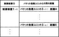
割当ユニット2は、位置に関する情報として、例えば、制御装置1とパケット処理ユニット3との間の距離を参照して、制御装置1の割当てを行ってもよい。管理DB21は、図8の例のように、制御装置1とパケット処理ユニット3との間の距離に関する情報を管理する。管理DB21は、例えば、各制御装置1について、通信システムに含まれるそれぞれのパケット処理ユニット3との間の距離を管理する。なお、割当ユニット2は、図7で例示した負荷状況と、図8で例示した距離とを考慮して、制御装置1の割り当てを行ってもよい。
The
制御装置1とパケット処理ユニット3との間の距離は、例えば、制御装置とパケット処理ユニットの位置関係に依存した距離や、通信システムのネットワーク構成(ネットワークトポロジ)に基づいて決定される距離である。また、制御装置1とパケット処理ユニット3との間の距離は、通信ホップ数であってもよい。
The distance between the
制御部20は、例えば、パケット処理ユニット3に割り当てる候補となる制御装置1のうち、パケット処理ユニット3との距離が最小となる制御装置を、パケット処理ユニットに割り当てる。
For example, among the
割当ユニット2は、位置に関する情報として、制御装置1とパケット処理ユニット3との間の通信コストを参照して、制御装置1の割当を行ってもよい。管理DB21は、図9の例のように、制御装置1とパケット処理ユニット3との間の通信コストに関する情報を管理する。管理DB21は、例えば、各制御装置1について、通信システムに含まれるそれぞれのパケット処理ユニット3との間の通信コストを管理する。なお、割当ユニット2は、図7で例示した負荷状況と、図9で例示した通信コストとを考慮して、制御装置1の割り当てを行ってもよい。
The
通信コストは、例えば、制御装置1とパケット処理ユニット3との間のラウンドトリップタイムや、制御装置1とパケット処理ユニット3との間の通信ホップ数等から求められる。
The communication cost is obtained from, for example, the round trip time between the
制御部20は、例えば、パケット処理ユニット3に割り当てる候補となる制御装置1のうち、パケット処理ユニット3との通信コストが最小となる制御装置を、パケット処理ユニットに割り当てる。
For example, among the
割当ユニット2が負荷を考慮して制御装置を割り当てるので、パケット処理ユニットを制御するための各制御装置の負荷が分散される。また、パケット処理ユニットの位置に基づいて制御装置を割り当てるので、パケット処理ユニットと制御装置間の通信スループットが向上する。
[第3の実施形態]
図10は、制御情報DB4の構成例を示す。
Since the
[Third Embodiment]
FIG. 10 shows a configuration example of the
制御情報DB4は、例えば、図10の例のように、パケット処理ユニット3毎に、制御情報を管理する。各制御装置1は、割り当てられたパケット処理ユニット3に対応する領域を参照し、パケット処理ユニット3に通知する処理規則を決定する。また、各制御装置1は、割り当てられたパケット処理ユニット3に対応する領域の情報を更新してもよい。
The
制御装置1は、例えば、パケット処理ユニット3から処理規則の通知を要求された場合に、制御情報DB4を参照して処理規則を決定する。また、制御装置1は、例えば、定期的に制御情報DB4を参照し、パケット処理ユニット3に通知すべき処理規則が確認された場合、パケット処理ユニット3に処理規則を通知してもよい。また、制御装置1は、制御情報DB4から、データベースが更新されたことを示す制御メッセージを受信したことに応じて、制御情報DB4を参照してもよい。
For example, when the notification of the processing rule is requested from the
図11は、あるパケット処理ユニット3に割り当てられた制御装置1が切り替わった場合の動作例を示す。図11の例では、パケット処理ユニット3−1に割り当てられた制御装置が、制御装置1−1から制御装置1−2に切り替わった例を示す。
FIG. 11 shows an operation example when the
割当ユニット2は、例えば、制御装置1に障害が発生した場合、障害が発生した制御装置に代替してパケット処理ユニット3を制御する制御装置1を決定する。割当ユニット2は、障害が発生した制御装置1を、決定した制御装置1に切り替える。
For example, when a failure occurs in the
制御装置1−1は、パケット処理ユニット3−1用の制御情報の参照を停止する。パケット処理ユニット3−1の制御を新たに担当する制御装置1−2は、パケット処理ユニット3−1用の制御情報の参照を開始し、パケット処理ユニット3−1の制御を引き継ぐ。
なお、制御装置1−1と1−2が制御情報DB4を共有しているため、制御装置1−2は、制御装置1−1との間で制御の引継ぎに関する処理を実行しなくてもよい。
The control device 1-1 stops referring to the control information for the packet processing unit 3-1. The control device 1-2 that newly takes charge of the control of the packet processing unit 3-1 starts referencing the control information for the packet processing unit 3-1, and takes over the control of the packet processing unit 3-1.
In addition, since the control apparatuses 1-1 and 1-2 share the
図12は、システムに新たな制御装置1が追加された場合の動作例を示す。図12の例では、システムに制御装置1−xが追加された例を示す。
FIG. 12 shows an operation example when a
割当ユニット2は、追加された制御装置1−xに、パケット処理ユニット3−xを割り当てる。制御装置1−xは、パケット処理ユニット3−x用の制御情報を参照し、パケット処理ユニット3−xを制御する。
The
第3の実施形態のように、各制御装置が制御情報DB4を共有することで、制御装置の増設によるスケールアウトや、障害回避が容易になる。制御装置は、単に共有データベースを参照するだけで、パケット処理ユニット3の制御を開始できるからである。制御装置1が複数のパケット処理ユニット3を集中制御する場合、制御装置1の負荷増大を抑止するため、制御装置1の数を増加させることが考えられる。第3の実施形態により、システム運用者は、非常に容易に制御装置1を増設することができる。また、障害回避のために制御装置を切り替える場合、データベースの参照先を変更するだけで、制御装置を切り替えることができ、システム運用者は、非常に容易に制御装置を切り替えることができる。
As in the third embodiment, since each control device shares the
また、各制御装置1が個別に制御情報を持たないので、パケット処理ユニット3の割当変更も容易になる。パケット処理ユニット3の割り当てが変更された場合、制御装置1は、制御情報DB4の参照先を変更するだけでよい。各制御装置1が個別に制御情報を持つ場合、割当変更時には、制御情報の移行が必要となる。しかし、各制御装置1が制御情報DB4を共有する構成とすることで、制御情報の移行等の処理は実行しなくてもよい。
[第4の実施形態]
第4の実施形態は、本願開示を、集中制御型のアーキテクチャを有するオープンフロー(OpenFlow)という技術を改良して実施する例を示す。
Further, since each
[Fourth Embodiment]
The fourth embodiment shows an example in which the present disclosure is implemented by improving a technique called OpenFlow having a central control type architecture.
図13及び図14を参照し、オープンフローについて説明する。 The open flow will be described with reference to FIGS. 13 and 14.
オープンフローは、通信をエンドツーエンドのフローとして認識し、フロー単位で経路制御、障害回復、負荷分散等を実行する。図13に、オープンフローにより構成された通信システムの概要を示す。なお、フローとは、例えば、所定の属性を有する一連の通信パケット群である。オープンフロースイッチ600は、オープンフロー技術を採用したネットワークスイッチである。オープンフローコントローラ700は、オープンフロースイッチ600を制御する情報処理装置である。
OpenFlow recognizes communication as an end-to-end flow, and performs path control, failure recovery, load balancing, and the like on a per-flow basis. FIG. 13 shows an outline of a communication system configured by OpenFlow. A flow is a series of communication packet groups having predetermined attributes, for example. The
オープンフロースイッチ600は、オープンフローコントローラ700との間に設定されたセキュアチャネル701を介して、オープンフローコントローラと通信する。オープンフローコントローラ700は、セキュアチャネル701を介して、オープンフロースイッチ600のフローテーブル601の設定を行う。なお、セキュアチャネル701は、スイッチとコントローラ間の通信の盗聴や改ざん等を防止するための処置がなされた通信経路である。
The
図14は、フローテーブル601の各エントリ(フローエントリ)の構成例を示す。フローエントリは、スイッチが受信したパケットの情報(例えば、宛先IPアドレスやVLAN ID等)と照合するためのマッチングルールと、パケットフロー毎の統計情報である統計情報(Counters)と、マッチングルールにマッチするパケットの処理方法を規定するアクション(Actions)とで構成される。 FIG. 14 shows a configuration example of each entry (flow entry) in the flow table 601. The flow entry matches a matching rule for matching with packet information (for example, destination IP address, VLAN ID, etc.) received by the switch, statistical information (Counters) that is statistical information for each packet flow, and the matching rule. And actions (Actions) that define the processing method of the packet to be processed.
オープンフロースイッチ600は、パケットを受信すると、フローテーブル601を参照する。オープンフロースイッチ600は、受信したパケットのヘッダ情報にマッチするフローエントリを検索する。受信パケットのヘッダ情報にマッチするエントリが検索された場合、オープンフロースイッチ600は、検索されたエントリのアクションフィールドに定義された処理方法に従って、受信パケットを処理する。処理方法は、例えば、“受信パケットを所定のポートから転送する”、“受信したパケットを廃棄する”、“受信パケットのヘッダの一部を書き換えて、所定のポートから転送する”といったことが規定されている。
When the
一方、受信パケットのヘッダ情報にマッチするエントリが見つからない場合、オープンフロースイッチ600は、例えば、セキュアチャネル701を介して、オープンフローコントローラ700に対して受信パケットを転送する。オープンフロースイッチ600は、受信パケットを転送することにより、コントローラに対して、受信パケットの処理方法を規定したフローエントリの設定を要求する。なお、受信パケットが、オープンフローコントローラ700へフローエントリの設定を要求することを規定したエントリにマッチした場合、オープンフロースイッチ600は、オープンフローコントローラ700に対してフローエントリの設定を要求してもよい。
On the other hand, if no entry matching the header information of the received packet is found, the
オープンフローコントローラ700は、受信パケットの処理方法を決定し、決定した処理方法を含むフローエントリをフローテーブル601に設定する。その後、オープンフロースイッチ600は、設定されたフローエントリにより、受信パケットと同一のフローに属する後続のパケットを処理する。
The
第4の実施形態のシステム構成は、第1、第2もしくは第3の実施形態と同様である。
図15、図16は、それぞれ、第4の実施形態の制御装置1Aとパケット処理ユニット3Aの構成の例を示す。図15の制御装置は、第3の実施形態のように、制御情報DB4を他の制御装置と共有する構成を有する。
The system configuration of the fourth embodiment is the same as that of the first, second, or third embodiment.
FIGS. 15 and 16 show examples of the configurations of the control device 1A and the packet processing unit 3A according to the fourth embodiment, respectively. The control device in FIG. 15 has a configuration in which the
図15は、第4の実施形態の制御装置1Aの構成の例を示す。制御装置1Aは、通信部10、制御部11、割当管理DB12を含む。 FIG. 15 shows an example of the configuration of the control device 1A of the fourth embodiment. The control device 1A includes a communication unit 10, a control unit 11, and an allocation management DB 12.
通信部10は、制御装置1Aに割り当てられたパケット処理ユニット3Aと通信する。
通信部10は、パケット処理ユニット3Aに、処理規則を通知する。通信部10は、パケット処理ユニット3Aから、処理規則の送信要求を受信する。通信部10は、パケット処理ユニット3Aとの間に構築された制御チャネルを介して、パケット処理ユニット3Aと通信する。
The communication unit 10 communicates with the packet processing unit 3A assigned to the control device 1A.
The communication unit 10 notifies the processing rules to the packet processing unit 3A. The communication unit 10 receives a processing rule transmission request from the packet processing unit 3A. The communication unit 10 communicates with the packet processing unit 3A via a control channel established with the packet processing unit 3A.
割当管理DB12は、制御装置1Aに割り当てられているパケット処理ユニット3Aを管理する。例えば、割当管理DB12は、制御装置1Aに割り当てられたパケット処理ユニットの識別情報を管理する。 The assignment management DB 12 manages the packet processing unit 3A assigned to the control device 1A. For example, the assignment management DB 12 manages the identification information of the packet processing unit assigned to the control device 1A.
制御部11は、割当管理DB12を参照し、制御装置1Aに割り当てられたパケット処理ユニット3Aを確認する。制御部11は、制御情報DB4から、制御装置1Aに割り当てられたパケット処理ユニット3Aに関する制御情報を参照する。制御部11は、参照した制御情報に基づいて、パケット処理ユニット3Aに通知する処理規則を決定する。制御部11は、例えば、パケット処理ユニット3Aからの要求に応じて、処理規則を決定する。また、制御部11は、例えば、自律的に制御情報DB4を参照し、予めパケット処理ユニット3Aに処理規則を通知してもよい。
The control unit 11 refers to the assignment management DB 12 and confirms the packet processing unit 3A assigned to the control device 1A. The control unit 11 refers to control information regarding the packet processing unit 3A assigned to the control device 1A from the control information DB4. The control unit 11 determines a processing rule to be notified to the packet processing unit 3A based on the referenced control information. For example, the control unit 11 determines a processing rule in response to a request from the packet processing unit 3A. For example, the control unit 11 may autonomously refer to the
図16は、第4の実施形態のパケット処理ユニット3Aの構成の例を示す。パケット処理ユニット3Aは、通信部30、パケット処理部31、処理規則DB32を含む。 FIG. 16 shows an example of the configuration of the packet processing unit 3A of the fourth embodiment. The packet processing unit 3A includes a communication unit 30, a packet processing unit 31, and a processing rule DB 32.
パケット処理部31は、パケットを受信すると、処理規則DB32から、受信したパケットに対応する処理規則を検索する。パケット処理部31は、例えば、処理規則の照合ルールと受信パケットのヘッダ情報とを比較し、パケットにマッチする照合ルールを有する処理規則を検索する。 When receiving the packet, the packet processing unit 31 searches the processing rule DB 32 for a processing rule corresponding to the received packet. For example, the packet processing unit 31 compares the processing rule matching rule with the header information of the received packet, and searches for a processing rule having a matching rule matching the packet.
パケット処理部31は、受信したパケットに対応する処理規則に規定された処理方法に従って、パケットを処理する。 The packet processing unit 31 processes a packet according to a processing method defined in a processing rule corresponding to the received packet.
パケット処理部31は、例えば、受信したパケットに対応する処理規則が存在しない場合や、検索された処理規則が制御装置への問い合わせを指示している場合に、制御装置に、受信パケットに対応する処理規則を問い合わせる。 For example, when there is no processing rule corresponding to the received packet, or when the retrieved processing rule instructs the control device to inquire, the packet processing unit 31 corresponds to the received packet. Queries processing rules.
割当ユニット2は、パケット処理ユニット3Aから受信した問い合わせを、パケット処理ユニット3Aに割り当てられている制御装置1Aに転送する。割当ユニット2は、例えば、パケット処理ユニット3Aに割り当てられている制御装置1Aを管理するデータベースを有する。例えば、割当ユニット2は、パケット処理ユニット3Aに割り当てられた制御情報の識別情報や通信アドレス(例えばIPアドレス)を管理するデータベースを有する。
The
図17は、第4の実施形態の動作例を示すシーケンス図である。図17は例であり、第4の実施形態の動作は図17に限定されない。 FIG. 17 is a sequence diagram illustrating an operation example of the fourth embodiment. FIG. 17 is an example, and the operation of the fourth embodiment is not limited to FIG.
割当ユニット2は、パケット処理ユニット3Aに対して、制御装置1Aを割り当てる。
割当ユニット2は、例えば、第2の実施形態に示された方法に基づいて、パケット処理ユニット3Aに割り当てる制御装置1Aを決定する。
The
The
パケット処理ユニット3Aは、割り当てられた制御装置1Aに対して、受信パケットに対応する処理規則を問い合わせる。 The packet processing unit 3A inquires the assigned control device 1A about the processing rule corresponding to the received packet.
問い合わせを受信した制御装置1Aは、処理規則を決定し、決定した処理規則をパケット処理ユニット3Aに通知する。 The control device 1A that has received the inquiry determines a processing rule and notifies the packet processing unit 3A of the determined processing rule.
パケット処理ユニット3Aは、通知された処理規則に従ってパケットを処理する。 The packet processing unit 3A processes the packet according to the notified processing rule.
第4の実施形態によれば、オープンフロー技術を利用して、本発明を実施することができる。
[第5の実施形態]
図18は、第5の実施形態のシステム構成の例を示す。
According to the fourth embodiment, the present invention can be implemented using the open flow technology.
[Fifth Embodiment]
FIG. 18 shows an example of the system configuration of the fifth embodiment.
第5の実施形態のシステムは、複数の制御装置1B、割当ユニット2、仮想スイッチ(vSwitch)3B、サーバ5、物理スイッチ6、仮想マシン(VM;Virtual Machine)7を含む。
The system of the fifth embodiment includes a plurality of control devices 1B, an
仮想スイッチ3Bは、サーバ5で動作するソフトウェアで構成されたネットワークスイッチである。仮想スイッチ3Bは、他の実施形態のパケット処理ユニット3に対応する機能を有する。つまり、仮想スイッチ3Bは、制御装置1Bによる制御に基づいて、パケットを処理する。なお、仮想スイッチ3Bは、例えば、物理スイッチ6で構成されるネットワークの端点(エッジ)に位置する。
The
複数の制御装置1Bは、制御情報DB4を共有する。 The plurality of control devices 1B share the control information DB4.
サーバ5では、ソフトウェアにより構成されたコンピュータである仮想マシン(VM)7が動作している。仮想マシン7は、仮想スイッチ3Bを介して、他の仮想マシン7と通信する。
In the server 5, a virtual machine (VM) 7 that is a computer configured by software operates. The virtual machine 7 communicates with other virtual machines 7 via the
割当ユニット2は、各仮想スイッチ3Bに対して、制御装置1Bを割り当てる。仮想スイッチ3Bは、割り当てられた制御装置1Bから通知された処理規則に従って、パケットを処理する。
The
サーバ5は、例えば、物理スイッチ6で構成されたネットワークの端部(エッジ)に位置する。この場合、制御装置1Bは、ネットワークのエッジに存在する仮想スイッチ3Bの動作を制御する。
For example, the server 5 is located at an end (edge) of a network constituted by the physical switches 6. In this case, the control device 1B controls the operation of the
仮想マシン7は、物理スイッチ6上に構築された仮想ネットワークを介して、他の仮想マシン7と通信する。仮想ネットワークは、例えば、VLAN(Virtual LAN)やNVGRE(Network Virtualization using Generic Routing Encapsulation)等のプロトコルに基づいて構築される。 The virtual machine 7 communicates with other virtual machines 7 via a virtual network constructed on the physical switch 6. The virtual network is constructed based on a protocol such as VLAN (Virtual LAN) or NVGRE (Network Virtualizing using Generic Routing Encapsulation).
図19を参照し、仮想マシン7間の通信動作の例を説明する。 An example of the communication operation between the virtual machines 7 will be described with reference to FIG.
他の仮想マシン7と通信する場合、仮想マシン7は、物理スイッチ6上に構築された仮想ネットワークを介して通信する。図19の例では、仮想マシン7−1と仮想マシン7−3との通信は、仮想ネットワークIDが“A”のトンネルを介して実行され、仮想マシン7−2と仮想マシン7−4との通信は、仮想ネットワークIDが“B”のトンネルを介して実行される。 When communicating with another virtual machine 7, the virtual machine 7 communicates via a virtual network constructed on the physical switch 6. In the example of FIG. 19, the communication between the virtual machine 7-1 and the virtual machine 7-3 is executed through a tunnel whose virtual network ID is “A”, and the virtual machine 7-2 and the virtual machine 7-4 The communication is executed through a tunnel having a virtual network ID “B”.
仮想スイッチ3B−1に割り当てられた制御装置1Bは、例えば、仮想マシン7−3宛のパケットに仮想ネットワークID“A”のタグ(例えば、VLANタグ)を付与することを規定した処理規則を、仮想スイッチ3B−1に通知する。仮想スイッチ3B−1は、例えば、仮想マシン7−1から仮想マシン7−3宛のパケットを受信すると、制御装置1Bの指示に従い、パケットに対して仮想ネットワークID“A”を示すタグを付与してパケットを転送する。
For example, the control device 1B assigned to the
仮想スイッチ3B−2に割り当てられた制御装置1Bは、例えば、仮想マシン7−4宛のパケットに仮想ネットワークID“B”のタグ(例えば、VLANタグ)を付与することを規定した処理規則を、仮想スイッチ3B−2に通知する。仮想スイッチ3B−2は、例えば、仮想マシン7−2から仮想マシン7−4宛のパケットを受信すると、制御装置1Bの指示に従い、パケットに対して仮想ネットワークID“B”を示すタグを付与してパケットを転送する。
For example, the control device 1B assigned to the
物理スイッチ6は、仮想ネットワークIDタグに基づくパケットの転送方法の設定(例えば、仮想ネットワークID“A”のパケットを転送すべきポート番号)を予め有しているものとする。 It is assumed that the physical switch 6 has a packet transfer method setting based on the virtual network ID tag (for example, a port number to which a packet of the virtual network ID “A” is to be transferred) in advance.
第5の実施形態のように、制御装置1Bが仮想スイッチ3Bのみを制御する構成により、制御装置1Bの負荷増大を抑止できる。また、通信システムの既存設備(例えば、物理スイッチ6)を置き換えることなく、制御装置による集中制御型のネットワークを導入できる。
As in the fifth embodiment, the configuration in which the control device 1B controls only the
最後に、本発明の好ましい形態を以下に要約する。
[形態1]
パケットの処理規則を決定する複数の制御装置と、
前記制御装置から通知された処理規則に従ってパケットを処理する複数のパケット処理手段と、
パケット処理手段の各々に対して、当該パケット処理手段を制御する制御装置を割当てる割当手段と、
前記複数の制御装置により共有され、前記処理規則に関する情報を格納するデータベースと、を含み、
前記制御装置の各々は、前記データベースを参照して前記処理規則を決定する、
通信システム。
[形態2]
前記制御装置の各々は、制御対象のパケット処理手段に対応する情報を前記データベースから検索し、検索された情報に基づいて、前記制御対象のパケット処理手段に送信する前記処理規則を決定する、
形態1の通信システム。
[形態3]
前記制御装置の各々は、制御対象のパケット処理手段が変更されたことに応じて、前記データベースの参照領域を変更する、
形態1又は2の通信システム。
[形態4]
前記データベースは、前記情報を、複数のパケット処理手段の各々に対応する領域に区分して格納する、
形態1乃至3のいずれか一項に記載の通信システム。
[形態5]
前記制御装置の各々は、所定の周期で前記データベースを参照し、前記割当手段により割当てられたパケット処理手段に通知する処理規則があるか否かを確認する、
形態1乃至4のいずれか一項に記載の通信システム。
[形態6]
前記制御装置の各々は、前記データベースの内容が変更されたことを示す通知を受信したことに応じて、前記データベースを参照する、
形態1乃至5のいずれか一項に記載の通信システム。
[形態7]
前記割当手段は、所定の規則に基づいて、それぞれのパケット処理手段に対して、当該パケット処理手段を制御する制御装置を割当てる、
形態1乃至6のいずれかの一項に記載の通信システム。
[形態8]
前記割当手段は、制御装置の負荷状況に基づいて、それぞれのパケット処理手段に対して、当該パケット処理手段を制御する制御装置を割当てる、
形態1乃至7のいずれか一項に記載の通信システム。
[形態9]
前記割当手段は、パケット処理手段の位置に関する情報に基づいて、それぞれのパケット処理手段に対して、当該パケット処理手段を制御する制御装置を割当てる、
形態1乃至8のいずれか一項に記載の通信システム。
[形態10]
前記割当手段は、それぞれのパケット処理手段に割り当てられた制御装置を他の制御装置に変更する機能を有する、
形態1乃至9のいずれか一項に記載の通信システム。
[形態11]
前記割当手段は、制御装置が停止した場合に、前記停止した制御装置に代わってパケット処理手段を制御する制御装置を決定する、
形態1乃至10のいずれか一項に記載の通信システム。
[形態12]
パケットの処理を制御する制御装置であって、
前記制御装置と他の制御装置とで共有されるデータベースを参照し、前記パケットの処理方法に関する処理規則を決定する第一の手段と、
決定した処理規則を、複数のパケット処理手段のうち、前記制御装置に割当てられたパケット処理手段に対して通知する第二の手段と、
を含む制御装置。
[形態13]
前記第一の手段は、前記制御装置に割当てられたパケット処理手段に対応する情報を前記データベースから検索し、検索された情報に基づいて、当該パケット処理手段に送信する前記処理規則を決定する、
形態12の制御装置。
[形態14]
前記第一の手段は、制御対象のパケット処理手段が変更されたことに応じて、前記データベースの参照領域を変更する、
形態12又は13の制御装置。
[形態15]
前記データベースは、前記情報を、複数のパケット処理手段の各々に対応する領域に区分して格納する、
形態12乃至14のいずれか一項に記載の制御装置。
[形態16]
前記制御装置は、所定の周期で前記データベースを参照し、割当手段により割当てられたパケット処理手段に通知する処理規則があるか否かを確認する、
形態12乃至15のいずれか一項に記載の制御装置。
[形態17]
前記制御装置は、前記データベースの内容が変更されたことを示す通知を受信したことに応じて、前記データベースを参照する、
形態12乃至16のいずれか一項に記載の制御装置。
[形態18]
複数の制御装置がパケットの処理を制御する通信方法であって、
複数のパケット処理手段の各々に、当該パケット処理手段を制御する制御装置を割当て、
前記制御装置の各々が、複数の制御装置で共有されるデータベースを参照して、パケットを処理するための処理規則を決定し、
前記制御装置の各々が、割当てられたパケット処理手段に対して、決定した処理規則を通知する、
通信方法。
[形態19]
パケットの処理を制御する制御装置における制御方法であって、
前記制御装置と他の制御装置とで共有されるデータベースを参照し、前記パケットの処理方法に関する処理規則を決定し、
決定した処理規則を、複数のパケット処理手段のうち、前記制御装置に割当てられたパケット処理手段に対して通知する、
制御方法。
[形態20]
パケットの処理を制御する制御装置に、
前記制御装置と他の制御装置とで共有されるデータベースを参照し、前記パケットの処理方法に関する処理規則を決定する処理と、
決定した処理規則を、複数のパケット処理手段のうち、前記制御装置に割当てられたパケット処理手段に対して通知する処理と、
を実行させるプログラム。
Finally, preferred forms of the invention are summarized below.
[Form 1]
A plurality of control devices for determining packet processing rules;
A plurality of packet processing means for processing packets according to the processing rule notified from the control device;
Assigning means for assigning a control device for controlling the packet processing means to each of the packet processing means;
A database that is shared by the plurality of control devices and stores information on the processing rules,
Each of the control devices determines the processing rule with reference to the database.
Communications system.
[Form 2]
Each of the control devices retrieves information corresponding to the packet processing unit to be controlled from the database, and determines the processing rule to be transmitted to the packet processing unit to be controlled based on the retrieved information.
The communication system of
[Form 3]
Each of the control devices changes the reference area of the database in response to the change of the packet processing means to be controlled.
The communication system of
[Form 4]
The database stores the information divided into areas corresponding to each of a plurality of packet processing means,
The communication system according to any one of
[Form 5]
Each of the control devices refers to the database at a predetermined cycle, and confirms whether there is a processing rule to notify the packet processing means allocated by the allocation means,
The communication system according to any one of
[Form 6]
Each of the control devices refers to the database in response to receiving a notification indicating that the contents of the database have been changed.
The communication system according to any one of
[Form 7]
The assigning means assigns a control device for controlling the packet processing means to each packet processing means based on a predetermined rule.
The communication system according to any one of
[Form 8]
The assigning means assigns a control device for controlling the packet processing means to each packet processing means based on the load status of the control device.
The communication system according to any one of
[Form 9]
The assigning means assigns a control device for controlling the packet processing means to each packet processing means based on information on the position of the packet processing means.
The communication system according to any one of
[Mode 10]
The assigning means has a function of changing a control device assigned to each packet processing means to another control device,
The communication system according to any one of
[Form 11]
The assigning means determines a control device for controlling the packet processing means in place of the stopped control device when the control device is stopped;
The communication system according to any one of
[Form 12]
A control device for controlling packet processing,
Referring to a database shared by the control device and another control device, a first means for determining a processing rule relating to the packet processing method;
A second means for notifying the determined processing rule to a packet processing means assigned to the control device among a plurality of packet processing means;
Control device including.
[Form 13]
The first means searches the database for information corresponding to the packet processing means assigned to the control device, and determines the processing rule to be transmitted to the packet processing means based on the searched information.
The control apparatus of form 12.
[Form 14]
The first means changes the reference area of the database in response to the change of the packet processing means to be controlled.
The control apparatus of form 12 or 13.
[Form 15]
The database stores the information divided into areas corresponding to each of a plurality of packet processing means,
The control device according to any one of forms 12 to 14.
[Form 16]
The control device refers to the database at a predetermined cycle, and confirms whether there is a processing rule to notify the packet processing means allocated by the allocation means,
The control device according to any one of forms 12 to 15.
[Form 17]
In response to receiving a notification indicating that the contents of the database have been changed, the control device refers to the database.
The control device according to any one of Forms 12 to 16.
[Form 18]
A communication method in which a plurality of control devices control packet processing,
A control device for controlling the packet processing means is assigned to each of the plurality of packet processing means,
Each of the control devices refers to a database shared by a plurality of control devices, determines a processing rule for processing a packet,
Each of the control devices notifies the assigned packet processing means of the determined processing rule.
Communication method.
[Form 19]
A control method in a control device for controlling packet processing,
Refer to a database shared by the control device and other control devices, determine a processing rule regarding the packet processing method,
Notifying the determined processing rule to the packet processing means allocated to the control device among the plurality of packet processing means.
Control method.
[Mode 20]
To the control device that controls packet processing,
A process of referring to a database shared by the control device and another control device, and determining a processing rule related to the packet processing method;
A process of notifying the determined processing rule to a packet processing means allocated to the control device among a plurality of packet processing means;
A program that executes
なお、引用した上記の特許文献等の各開示は、本書に引用をもって繰り込むものとする。本発明の全開示(請求の範囲を含む)の枠内において、さらにその基本的技術思想に基づいて、実施形態ないし実施例の変更・調整が可能である。また、本発明の請求の範囲の枠内において種々の開示要素(各請求項の各要素、各実施形態ないし実施例の各要素、各図面の各要素等を含む)の多様な組み合わせ、ないし、選択が可能である。すなわち、本発明は、請求の範囲を含む全開示、技術的思想にしたがって当業者であればなし得るであろう各種変形、修正を含むことは勿論である。特に、本書に記載した数値範囲については、当該範囲内に含まれる任意の数値ないし小範囲が、別段の記載のない場合でも具体的に記載されているものと解釈されるべきである。 Each disclosure of the cited patent documents and the like cited above is incorporated herein by reference. Within the scope of the entire disclosure (including claims) of the present invention, the embodiments and examples can be changed and adjusted based on the basic technical concept. Various disclosed elements (including each element of each claim, each element of each embodiment or example, each element of each drawing, etc.) within the scope of the claims of the present invention, Selection is possible. That is, the present invention of course includes various variations and modifications that could be made by those skilled in the art according to the entire disclosure including the claims and the technical idea. In particular, with respect to the numerical ranges described in this document, any numerical value or small range included in the range should be construed as being specifically described even if there is no specific description.
1、1A、1B 制御装置
10 通信部
11、20 制御部
12 割当管理DB
2 割当ユニット
21 管理DB
3、3A パケット処理ユニット
3B 仮想スイッチ
30 通信部
31 パケット処理部
32 処理規則DB
4 制御情報DB
5 サーバ
6 物理スイッチ
7 仮想マシン(VM)
600 オープンフロースイッチ
601 フローテーブル
700 オープンフローコントローラ
701 セキュアチャネル
1, 1A, 1B Control device 10
2 Allocation unit 21 Management DB
3, 3A
4 Control information DB
5 Server 6 Physical switch 7 Virtual machine (VM)
600
Claims (20)
前記制御装置から通知された処理規則に従ってパケットを処理する複数のパケット処理手段と、
パケット処理手段の各々に対して、当該パケット処理手段を制御する制御装置を割当てる割当手段と、
前記複数の制御装置により共有され、前記処理規則に関する情報を格納するデータベースと、を含み、
前記制御装置の各々は、パケット処理手段から処理規則の通知を要求されると、前記データベースを参照して前記パケットを処理するための処理規則を検索し、前記制御装置に割当てられたパケット処理手段のうち、処理規則の通知を要求した前記パケット処理手段に、検索した処理規則を通知する、
通信システム。 A plurality of control devices for retrieving packet processing rules;
A plurality of packet processing means for processing packets according to the processing rule notified from the control device;
Assigning means for assigning a control device for controlling the packet processing means to each of the packet processing means;
A database that is shared by the plurality of control devices and stores information on the processing rules,
Each of the control devices, when requested by the packet processing means to notify the processing rules, searches the processing rules for processing the packets with reference to the database, and packet processing means assigned to the control devices Among them, the packet processing means that has requested the processing rule notification is notified of the searched processing rule.
Communications system.
請求項1の通信システム。 Each of the control devices retrieves information corresponding to the packet processing unit to be controlled from the database, and determines the processing rule to be transmitted to the packet processing unit to be controlled based on the retrieved information.
The communication system according to claim 1.
請求項1又は2の通信システム。 Each of the control devices changes the reference area of the database in response to the change of the packet processing means to be controlled.
The communication system according to claim 1 or 2.
請求項1乃至3のいずれか一項に記載の通信システム。 The database stores the information divided into areas corresponding to each of a plurality of packet processing means,
The communication system according to any one of claims 1 to 3.
請求項1乃至4のいずれか一項に記載の通信システム。 Each of the control devices refers to the database at a predetermined cycle, and confirms whether there is a processing rule to notify the packet processing means allocated by the allocation means,
The communication system according to any one of claims 1 to 4.
請求項1乃至5のいずれか一項に記載の通信システム。 Each of the control devices refers to the database in response to receiving a notification indicating that the contents of the database have been changed.
The communication system according to any one of claims 1 to 5.
請求項1乃至6のいずれかの一項に記載の通信システム。 The assigning means assigns a control device for controlling the packet processing means to each packet processing means based on a predetermined rule.
The communication system according to any one of claims 1 to 6.
請求項1乃至7のいずれか一項に記載の通信システム。 The assigning means assigns a control device for controlling the packet processing means to each packet processing means based on the load status of the control device.
The communication system according to any one of claims 1 to 7.
請求項1乃至8のいずれか一項に記載の通信システム。 The assigning means assigns a control device for controlling the packet processing means to each packet processing means based on information on the position of the packet processing means.
The communication system according to any one of claims 1 to 8.
請求項1乃至9のいずれか一項に記載の通信システム。 The assigning means has a function of changing a control device assigned to each packet processing means to another control device,
The communication system according to any one of claims 1 to 9.
請求項1乃至10のいずれか一項に記載の通信システム。 The assigning means determines a control device for controlling the packet processing means in place of the stopped control device when the control device is stopped;
The communication system according to any one of claims 1 to 10.
パケット処理手段から処理規則の通知を要求されると、前記制御装置と他の制御装置とで共有されるデータベースを参照し、前記パケットの処理方法に関する処理規則を検索する第一の手段と、
検索した前記処理規則を、前記制御装置に割当てられたパケット処理手段のうち、処理規則の通知を要求した前記パケット処理手段に対して通知する第二の手段と、
を含む制御装置。 A control device for controlling packet processing,
When a notification of a processing rule is requested from the packet processing means, a first means for searching a processing rule related to the packet processing method with reference to a database shared by the control device and another control device;
A second means for notifying the packet processing means assigned to the control device of the retrieved processing rule to the packet processing means that has requested the notification of the processing rule;
Control device including.
請求項12の制御装置。 The first means searches the database for information corresponding to the packet processing means assigned to the control device, and determines the processing rule to be transmitted to the packet processing means based on the searched information.
The control device according to claim 12.
請求項12又は13の制御装置。 The first means changes the reference area of the database in response to the change of the packet processing means to be controlled.
The control device according to claim 12 or 13.
請求項13の制御装置。 The database stores the information divided into areas corresponding to each of a plurality of packet processing means,
The control device according to claim 13 .
請求項12乃至15のいずれか一項に記載の制御装置。 The control device refers to the database at a predetermined cycle, and confirms whether there is a processing rule to notify the packet processing means allocated by the allocation means,
The control device according to any one of claims 12 to 15.
請求項12乃至16のいずれか一項に記載の制御装置。 In response to receiving a notification indicating that the contents of the database have been changed, the control device refers to the database.
The control device according to any one of claims 12 to 16.
複数のパケット処理手段の各々に、当該パケット処理手段を制御する制御装置を割当て、
前記制御装置の各々が、パケット処理手段から処理規則の通知を要求されると、複数の制御装置で共有されるデータベースを参照して、前記パケットを処理するための処理規則を検索し、
前記制御装置の各々が、割当てられたパケット処理手段に対して、検索した前記処理規則を通知する、
通信方法。 A communication method in which a plurality of control devices control packet processing,
A control device for controlling the packet processing means is assigned to each of the plurality of packet processing means,
When each of the control devices is requested to notify the processing rules from the packet processing means, the processing devices for processing the packets are searched with reference to a database shared by a plurality of control devices,
Each of the control devices notifies the assigned packet processing means of the searched processing rule.
Communication method.
パケット処理手段から処理規則の通知を要求されると、前記制御装置と他の制御装置とで共有されるデータベースを参照し、前記パケットの処理方法に関する処理規則を検索し、
検索した前記処理規則を、前記制御装置に割当てられたパケット処理手段のうち、処理規則の通知を要求した前記パケット処理手段に対して通知する、
制御方法。 A control method in a control device for controlling packet processing,
When a notification of a processing rule is requested from the packet processing means, a database shared by the control device and another control device is referred to search for a processing rule related to the packet processing method,
Notifying the packet processing means allocated to the control device to the packet processing means that has requested notification of the processing rule, the searched processing rules.
Control method.
パケット処理手段から処理規則の通知を要求されると、前記制御装置と他の制御装置とで共有されるデータベースを参照し、前記パケットの処理方法に関する処理規則を検索する処理と、
検索した前記処理規則を、前記制御装置に割当てられたパケット処理手段のうち、処理規則の通知を要求した前記パケット処理手段に対して通知する処理と、
を実行させるプログラム。 To the control device that controls packet processing,
When a notification of a processing rule is requested from the packet processing means, a process for referring to a database shared by the control device and another control device and searching for a processing rule related to the packet processing method;
A process of notifying the packet processing means assigned to the control device of the retrieved processing rule to the packet processing means that has requested the notification of the processing rule;
A program that executes
Priority Applications (1)
| Application Number | Priority Date | Filing Date | Title |
|---|---|---|---|
| JP2014560154A JP6323339B2 (en) | 2012-06-14 | 2013-06-12 | COMMUNICATION SYSTEM, CONTROL DEVICE, COMMUNICATION METHOD, CONTROL METHOD, AND PROGRAM |
Applications Claiming Priority (4)
| Application Number | Priority Date | Filing Date | Title |
|---|---|---|---|
| JP2012135031 | 2012-06-14 | ||
| JP2012135031 | 2012-06-14 | ||
| JP2014560154A JP6323339B2 (en) | 2012-06-14 | 2013-06-12 | COMMUNICATION SYSTEM, CONTROL DEVICE, COMMUNICATION METHOD, CONTROL METHOD, AND PROGRAM |
| PCT/JP2013/003673 WO2013187054A1 (en) | 2012-06-14 | 2013-06-12 | Communication system, control apparatus, communication method, control method and program |
Publications (2)
| Publication Number | Publication Date |
|---|---|
| JP2015519765A JP2015519765A (en) | 2015-07-09 |
| JP6323339B2 true JP6323339B2 (en) | 2018-05-16 |
Family
ID=49757899
Family Applications (1)
| Application Number | Title | Priority Date | Filing Date |
|---|---|---|---|
| JP2014560154A Active JP6323339B2 (en) | 2012-06-14 | 2013-06-12 | COMMUNICATION SYSTEM, CONTROL DEVICE, COMMUNICATION METHOD, CONTROL METHOD, AND PROGRAM |
Country Status (8)
| Country | Link |
|---|---|
| US (1) | US10212084B2 (en) |
| EP (1) | EP2862322B1 (en) |
| JP (1) | JP6323339B2 (en) |
| KR (1) | KR20150016314A (en) |
| CN (1) | CN104365069A (en) |
| HK (1) | HK1208572A1 (en) |
| IN (1) | IN2014DN10624A (en) |
| WO (1) | WO2013187054A1 (en) |
Families Citing this family (7)
| Publication number | Priority date | Publication date | Assignee | Title |
|---|---|---|---|---|
| US9397917B2 (en) | 2014-01-10 | 2016-07-19 | Huawei Technologies Co., Ltd. | System and method for zoning in software defined networks |
| EP3116176A4 (en) * | 2014-03-06 | 2017-11-08 | Nec Corporation | Communication system, control device, communication device, and communication method |
| US9445279B2 (en) | 2014-12-05 | 2016-09-13 | Huawei Technologies Co., Ltd. | Systems and methods for placing virtual serving gateways for mobility management |
| JP6787475B2 (en) | 2016-07-21 | 2020-11-18 | 日本電気株式会社 | Communication equipment, systems, rollback methods and programs |
| JP6543600B2 (en) * | 2016-08-17 | 2019-07-10 | 日本電信電話株式会社 | Management system and management method |
| CN107592226A (en) * | 2017-09-15 | 2018-01-16 | 厦门拓宝科技有限公司 | The centralized management method of a variety of distinct device types |
| JP7003864B2 (en) * | 2018-07-24 | 2022-02-10 | 日本電信電話株式会社 | Sorting device, communication system and sorting method |
Family Cites Families (15)
| Publication number | Priority date | Publication date | Assignee | Title |
|---|---|---|---|---|
| JP4169710B2 (en) | 2004-02-23 | 2008-10-22 | 日本電信電話株式会社 | BGP route information management system and program thereof |
| JP2006227963A (en) * | 2005-02-18 | 2006-08-31 | Fujitsu Ltd | Multistage load balancer and its method and program |
| US7536481B2 (en) * | 2005-02-25 | 2009-05-19 | Microsoft Corporation | Method and system for re-synchronizing end points when an intermediary detects that the end points may be unsynchronized |
| CN100389392C (en) * | 2006-05-29 | 2008-05-21 | 杭州华三通信技术有限公司 | Method for realizing load uniform in clustering system, system and storage controller |
| US20080189769A1 (en) | 2007-02-01 | 2008-08-07 | Martin Casado | Secure network switching infrastructure |
| JP2009213097A (en) * | 2008-03-06 | 2009-09-17 | Nippon Telegr & Teleph Corp <Ntt> | Information recording system and information recording method |
| JP4559512B2 (en) * | 2008-08-11 | 2010-10-06 | 日本電信電話株式会社 | Packet transfer system and packet transfer method |
| US20120250496A1 (en) | 2009-11-26 | 2012-10-04 | Takeshi Kato | Load distribution system, load distribution method, and program |
| WO2011120000A2 (en) * | 2010-03-26 | 2011-09-29 | Citrix Systems, Inc. | Systems and methods for link load balancing on a multi-core device |
| JP5670796B2 (en) * | 2010-09-06 | 2015-02-18 | 西日本電信電話株式会社 | Method and communication apparatus for realizing virtual system operation |
| US9001827B2 (en) * | 2010-12-17 | 2015-04-07 | Big Switch Networks, Inc. | Methods for configuring network switches |
| US9185056B2 (en) * | 2011-09-20 | 2015-11-10 | Big Switch Networks, Inc. | System and methods for controlling network traffic through virtual switches |
| US8705536B2 (en) * | 2012-03-05 | 2014-04-22 | Telefonaktiebolaget L M Ericsson (Publ) | Methods of operating forwarding elements including shadow tables and related forwarding elements |
| US8730806B2 (en) * | 2012-04-03 | 2014-05-20 | Telefonaktiebolaget L M Ericsson (Publ) | Congestion control and resource allocation in split architecture networks |
| US8908539B1 (en) * | 2012-05-25 | 2014-12-09 | Google Inc. | Systems and methods for testing network connections of a centrally-controlled network |
-
2013
- 2013-06-12 IN IN10624DEN2014 patent/IN2014DN10624A/en unknown
- 2013-06-12 US US14/407,434 patent/US10212084B2/en active Active
- 2013-06-12 WO PCT/JP2013/003673 patent/WO2013187054A1/en active Application Filing
- 2013-06-12 EP EP13803867.4A patent/EP2862322B1/en active Active
- 2013-06-12 CN CN201380030383.0A patent/CN104365069A/en active Pending
- 2013-06-12 JP JP2014560154A patent/JP6323339B2/en active Active
- 2013-06-12 KR KR1020147034165A patent/KR20150016314A/en not_active Application Discontinuation
-
2015
- 2015-09-15 HK HK15109019.1A patent/HK1208572A1/en unknown
Also Published As
| Publication number | Publication date |
|---|---|
| JP2015519765A (en) | 2015-07-09 |
| CN104365069A (en) | 2015-02-18 |
| US20150156113A1 (en) | 2015-06-04 |
| US10212084B2 (en) | 2019-02-19 |
| WO2013187054A1 (en) | 2013-12-19 |
| HK1208572A1 (en) | 2016-03-04 |
| EP2862322A1 (en) | 2015-04-22 |
| EP2862322A4 (en) | 2016-01-20 |
| IN2014DN10624A (en) | 2015-09-11 |
| KR20150016314A (en) | 2015-02-11 |
| EP2862322B1 (en) | 2019-10-02 |
Similar Documents
| Publication | Publication Date | Title |
|---|---|---|
| JP6323339B2 (en) | COMMUNICATION SYSTEM, CONTROL DEVICE, COMMUNICATION METHOD, CONTROL METHOD, AND PROGRAM | |
| JP5850068B2 (en) | Control device, communication system, communication method, and program | |
| WO2014136864A1 (en) | Packet rewriting apparatus, control apparatus, communication system, packet transmitting method and program | |
| WO2012133290A1 (en) | Computer system, and communication method | |
| US20120170477A1 (en) | Computer, communication system, network connection switching method, and program | |
| US20130286844A1 (en) | Information system, control apparatus, communication method, and program | |
| US9614754B2 (en) | Method, device, and system for packet routing in a network | |
| US20180077048A1 (en) | Controller, control method and program | |
| US9130886B2 (en) | Communication system, controller, switch, storage managing apparatus and communication method | |
| JP2010161473A (en) | Communication system, management computer, stacked switch, flow route determination method | |
| US20170295035A1 (en) | Selecting an optimal network device for reporting flow table misses upon expiry of a flow in a software defined network | |
| WO2014112616A1 (en) | Control apparatus, communication apparatus, communication system, switch control method and program | |
| JP5904285B2 (en) | Communication system, virtual network management device, communication node, communication method, and program | |
| WO2014157512A1 (en) | System for providing virtual machines, device for determining paths, method for controlling paths, and program | |
| WO2017090535A1 (en) | Flow control device, communication system, method for controlling flow, and recording medium | |
| WO2014133025A1 (en) | Communication system, host controller, network control method, and program | |
| JP2015525982A (en) | COMMUNICATION METHOD, COMMUNICATION SYSTEM, INFORMATION PROCESSING DEVICE, COMMUNICATION TERMINAL, AND PROGRAM | |
| US20150381775A1 (en) | Communication system, communication method, control apparatus, control apparatus control method, and program | |
| JP6292128B2 (en) | COMMUNICATION SYSTEM, NODE, CONTROL DEVICE, COMMUNICATION METHOD, AND PROGRAM | |
| WO2015133561A1 (en) | Communication system, control device, communication device, and communication method | |
| JP5889813B2 (en) | Communication system and program | |
| US9860178B2 (en) | Control message relay apparatus, control message relay method, and program | |
| WO2017110712A1 (en) | Controller, switch, communication system, method for setting flow entries, method for processing packets, and program | |
| JP5768600B2 (en) | COMMUNICATION SYSTEM, CONTROL DEVICE, PACKET TRANSFER METHOD, AND PROGRAM | |
| WO2014142081A1 (en) | Transfer node, control device, communication system, packet processing method and program |
Legal Events
| Date | Code | Title | Description |
|---|---|---|---|
| A621 | Written request for application examination |
Free format text: JAPANESE INTERMEDIATE CODE: A621 Effective date: 20160511 |
|
| A131 | Notification of reasons for refusal |
Free format text: JAPANESE INTERMEDIATE CODE: A131 Effective date: 20170425 |
|
| A521 | Request for written amendment filed |
Free format text: JAPANESE INTERMEDIATE CODE: A523 Effective date: 20170626 |
|
| A131 | Notification of reasons for refusal |
Free format text: JAPANESE INTERMEDIATE CODE: A131 Effective date: 20171205 |
|
| A521 | Request for written amendment filed |
Free format text: JAPANESE INTERMEDIATE CODE: A523 Effective date: 20171228 |
|
| TRDD | Decision of grant or rejection written | ||
| A01 | Written decision to grant a patent or to grant a registration (utility model) |
Free format text: JAPANESE INTERMEDIATE CODE: A01 Effective date: 20180313 |
|
| A61 | First payment of annual fees (during grant procedure) |
Free format text: JAPANESE INTERMEDIATE CODE: A61 Effective date: 20180326 |
|
| R150 | Certificate of patent or registration of utility model |
Ref document number: 6323339 Country of ref document: JP Free format text: JAPANESE INTERMEDIATE CODE: R150 |