JP6317690B2 - Transdermal absorption sheet and method for producing the same - Google Patents
Transdermal absorption sheet and method for producing the same Download PDFInfo
- Publication number
- JP6317690B2 JP6317690B2 JP2015041385A JP2015041385A JP6317690B2 JP 6317690 B2 JP6317690 B2 JP 6317690B2 JP 2015041385 A JP2015041385 A JP 2015041385A JP 2015041385 A JP2015041385 A JP 2015041385A JP 6317690 B2 JP6317690 B2 JP 6317690B2
- Authority
- JP
- Japan
- Prior art keywords
- needle
- mold
- drug
- sheet
- convex
- Prior art date
- Legal status (The legal status is an assumption and is not a legal conclusion. Google has not performed a legal analysis and makes no representation as to the accuracy of the status listed.)
- Active
Links
Images


Classifications
-
- A—HUMAN NECESSITIES
- A61—MEDICAL OR VETERINARY SCIENCE; HYGIENE
- A61M—DEVICES FOR INTRODUCING MEDIA INTO, OR ONTO, THE BODY; DEVICES FOR TRANSDUCING BODY MEDIA OR FOR TAKING MEDIA FROM THE BODY; DEVICES FOR PRODUCING OR ENDING SLEEP OR STUPOR
- A61M37/00—Other apparatus for introducing media into the body; Percutany, i.e. introducing medicines into the body by diffusion through the skin
- A61M37/0015—Other apparatus for introducing media into the body; Percutany, i.e. introducing medicines into the body by diffusion through the skin by using microneedles
-
- A—HUMAN NECESSITIES
- A61—MEDICAL OR VETERINARY SCIENCE; HYGIENE
- A61M—DEVICES FOR INTRODUCING MEDIA INTO, OR ONTO, THE BODY; DEVICES FOR TRANSDUCING BODY MEDIA OR FOR TAKING MEDIA FROM THE BODY; DEVICES FOR PRODUCING OR ENDING SLEEP OR STUPOR
- A61M37/00—Other apparatus for introducing media into the body; Percutany, i.e. introducing medicines into the body by diffusion through the skin
-
- B—PERFORMING OPERATIONS; TRANSPORTING
- B29—WORKING OF PLASTICS; WORKING OF SUBSTANCES IN A PLASTIC STATE IN GENERAL
- B29C—SHAPING OR JOINING OF PLASTICS; SHAPING OF MATERIAL IN A PLASTIC STATE, NOT OTHERWISE PROVIDED FOR; AFTER-TREATMENT OF THE SHAPED PRODUCTS, e.g. REPAIRING
- B29C39/00—Shaping by casting, i.e. introducing the moulding material into a mould or between confining surfaces without significant moulding pressure; Apparatus therefor
- B29C39/02—Shaping by casting, i.e. introducing the moulding material into a mould or between confining surfaces without significant moulding pressure; Apparatus therefor for making articles of definite length, i.e. discrete articles
- B29C39/026—Shaping by casting, i.e. introducing the moulding material into a mould or between confining surfaces without significant moulding pressure; Apparatus therefor for making articles of definite length, i.e. discrete articles characterised by the shape of the surface
-
- B—PERFORMING OPERATIONS; TRANSPORTING
- B29—WORKING OF PLASTICS; WORKING OF SUBSTANCES IN A PLASTIC STATE IN GENERAL
- B29C—SHAPING OR JOINING OF PLASTICS; SHAPING OF MATERIAL IN A PLASTIC STATE, NOT OTHERWISE PROVIDED FOR; AFTER-TREATMENT OF THE SHAPED PRODUCTS, e.g. REPAIRING
- B29C39/00—Shaping by casting, i.e. introducing the moulding material into a mould or between confining surfaces without significant moulding pressure; Apparatus therefor
- B29C39/22—Component parts, details or accessories; Auxiliary operations
- B29C39/26—Moulds or cores
-
- B—PERFORMING OPERATIONS; TRANSPORTING
- B81—MICROSTRUCTURAL TECHNOLOGY
- B81B—MICROSTRUCTURAL DEVICES OR SYSTEMS, e.g. MICROMECHANICAL DEVICES
- B81B1/00—Devices without movable or flexible elements, e.g. microcapillary devices
-
- B—PERFORMING OPERATIONS; TRANSPORTING
- B81—MICROSTRUCTURAL TECHNOLOGY
- B81B—MICROSTRUCTURAL DEVICES OR SYSTEMS, e.g. MICROMECHANICAL DEVICES
- B81B1/00—Devices without movable or flexible elements, e.g. microcapillary devices
- B81B1/006—Microdevices formed as a single homogeneous piece, i.e. wherein the mechanical function is obtained by the use of the device, e.g. cutters
- B81B1/008—Microtips
-
- B—PERFORMING OPERATIONS; TRANSPORTING
- B81—MICROSTRUCTURAL TECHNOLOGY
- B81B—MICROSTRUCTURAL DEVICES OR SYSTEMS, e.g. MICROMECHANICAL DEVICES
- B81B7/00—Microstructural systems; Auxiliary parts of microstructural devices or systems
- B81B7/04—Networks or arrays of similar microstructural devices
-
- B—PERFORMING OPERATIONS; TRANSPORTING
- B81—MICROSTRUCTURAL TECHNOLOGY
- B81C—PROCESSES OR APPARATUS SPECIALLY ADAPTED FOR THE MANUFACTURE OR TREATMENT OF MICROSTRUCTURAL DEVICES OR SYSTEMS
- B81C1/00—Manufacture or treatment of devices or systems in or on a substrate
-
- B—PERFORMING OPERATIONS; TRANSPORTING
- B81—MICROSTRUCTURAL TECHNOLOGY
- B81C—PROCESSES OR APPARATUS SPECIALLY ADAPTED FOR THE MANUFACTURE OR TREATMENT OF MICROSTRUCTURAL DEVICES OR SYSTEMS
- B81C1/00—Manufacture or treatment of devices or systems in or on a substrate
- B81C1/00015—Manufacture or treatment of devices or systems in or on a substrate for manufacturing microsystems
- B81C1/00023—Manufacture or treatment of devices or systems in or on a substrate for manufacturing microsystems without movable or flexible elements
- B81C1/00111—Tips, pillars, i.e. raised structures
-
- A—HUMAN NECESSITIES
- A61—MEDICAL OR VETERINARY SCIENCE; HYGIENE
- A61M—DEVICES FOR INTRODUCING MEDIA INTO, OR ONTO, THE BODY; DEVICES FOR TRANSDUCING BODY MEDIA OR FOR TAKING MEDIA FROM THE BODY; DEVICES FOR PRODUCING OR ENDING SLEEP OR STUPOR
- A61M37/00—Other apparatus for introducing media into the body; Percutany, i.e. introducing medicines into the body by diffusion through the skin
- A61M37/0015—Other apparatus for introducing media into the body; Percutany, i.e. introducing medicines into the body by diffusion through the skin by using microneedles
- A61M2037/0023—Drug applicators using microneedles
-
- A—HUMAN NECESSITIES
- A61—MEDICAL OR VETERINARY SCIENCE; HYGIENE
- A61M—DEVICES FOR INTRODUCING MEDIA INTO, OR ONTO, THE BODY; DEVICES FOR TRANSDUCING BODY MEDIA OR FOR TAKING MEDIA FROM THE BODY; DEVICES FOR PRODUCING OR ENDING SLEEP OR STUPOR
- A61M37/00—Other apparatus for introducing media into the body; Percutany, i.e. introducing medicines into the body by diffusion through the skin
- A61M37/0015—Other apparatus for introducing media into the body; Percutany, i.e. introducing medicines into the body by diffusion through the skin by using microneedles
- A61M2037/0046—Solid microneedles
-
- A—HUMAN NECESSITIES
- A61—MEDICAL OR VETERINARY SCIENCE; HYGIENE
- A61M—DEVICES FOR INTRODUCING MEDIA INTO, OR ONTO, THE BODY; DEVICES FOR TRANSDUCING BODY MEDIA OR FOR TAKING MEDIA FROM THE BODY; DEVICES FOR PRODUCING OR ENDING SLEEP OR STUPOR
- A61M37/00—Other apparatus for introducing media into the body; Percutany, i.e. introducing medicines into the body by diffusion through the skin
- A61M37/0015—Other apparatus for introducing media into the body; Percutany, i.e. introducing medicines into the body by diffusion through the skin by using microneedles
- A61M2037/0053—Methods for producing microneedles
-
- B—PERFORMING OPERATIONS; TRANSPORTING
- B29—WORKING OF PLASTICS; WORKING OF SUBSTANCES IN A PLASTIC STATE IN GENERAL
- B29K—INDEXING SCHEME ASSOCIATED WITH SUBCLASSES B29B, B29C OR B29D, RELATING TO MOULDING MATERIALS OR TO MATERIALS FOR MOULDS, REINFORCEMENTS, FILLERS OR PREFORMED PARTS, e.g. INSERTS
- B29K2105/00—Condition, form or state of moulded material or of the material to be shaped
- B29K2105/0005—Condition, form or state of moulded material or of the material to be shaped containing compounding ingredients
- B29K2105/0035—Medical or pharmaceutical agents
-
- B—PERFORMING OPERATIONS; TRANSPORTING
- B29—WORKING OF PLASTICS; WORKING OF SUBSTANCES IN A PLASTIC STATE IN GENERAL
- B29K—INDEXING SCHEME ASSOCIATED WITH SUBCLASSES B29B, B29C OR B29D, RELATING TO MOULDING MATERIALS OR TO MATERIALS FOR MOULDS, REINFORCEMENTS, FILLERS OR PREFORMED PARTS, e.g. INSERTS
- B29K2105/00—Condition, form or state of moulded material or of the material to be shaped
- B29K2105/0058—Liquid or visquous
- B29K2105/0073—Solution
-
- B—PERFORMING OPERATIONS; TRANSPORTING
- B29—WORKING OF PLASTICS; WORKING OF SUBSTANCES IN A PLASTIC STATE IN GENERAL
- B29K—INDEXING SCHEME ASSOCIATED WITH SUBCLASSES B29B, B29C OR B29D, RELATING TO MOULDING MATERIALS OR TO MATERIALS FOR MOULDS, REINFORCEMENTS, FILLERS OR PREFORMED PARTS, e.g. INSERTS
- B29K2883/00—Use of polymers having silicon, with or without sulfur, nitrogen, oxygen, or carbon only, in the main chain, as mould material
-
- B—PERFORMING OPERATIONS; TRANSPORTING
- B29—WORKING OF PLASTICS; WORKING OF SUBSTANCES IN A PLASTIC STATE IN GENERAL
- B29L—INDEXING SCHEME ASSOCIATED WITH SUBCLASS B29C, RELATING TO PARTICULAR ARTICLES
- B29L2031/00—Other particular articles
- B29L2031/753—Medical equipment; Accessories therefor
- B29L2031/7544—Injection needles, syringes
-
- B—PERFORMING OPERATIONS; TRANSPORTING
- B81—MICROSTRUCTURAL TECHNOLOGY
- B81B—MICROSTRUCTURAL DEVICES OR SYSTEMS, e.g. MICROMECHANICAL DEVICES
- B81B2201/00—Specific applications of microelectromechanical systems
- B81B2201/05—Microfluidics
- B81B2201/055—Microneedles
Landscapes
- Engineering & Computer Science (AREA)
- Health & Medical Sciences (AREA)
- Microelectronics & Electronic Packaging (AREA)
- Computer Hardware Design (AREA)
- Manufacturing & Machinery (AREA)
- Heart & Thoracic Surgery (AREA)
- Life Sciences & Earth Sciences (AREA)
- Medical Informatics (AREA)
- Anesthesiology (AREA)
- Biomedical Technology (AREA)
- Veterinary Medicine (AREA)
- Hematology (AREA)
- Dermatology (AREA)
- Animal Behavior & Ethology (AREA)
- General Health & Medical Sciences (AREA)
- Public Health (AREA)
- Analytical Chemistry (AREA)
- Chemical & Material Sciences (AREA)
- Media Introduction/Drainage Providing Device (AREA)
- Micromachines (AREA)
- Medicinal Preparation (AREA)
Description
本発明は、経皮吸収シート、及びその製造方法に関する。 The present invention relates to a transdermal absorption sheet and a method for producing the same.
近年、薬剤を含有する複数の針状凸部(微小針又はマイクロニードルとも称する。)を有する経皮吸収シートが、薬剤を皮膚内に送達するために用いられている。一般的には、経皮吸収シートを皮膚に押し付けて、針状凸部を皮膚内に挿入することにより、針状凸部の薬剤が皮膚内に送達される。 In recent years, a percutaneous absorption sheet having a plurality of needle-like convex portions (also referred to as microneedles or microneedles) containing a drug has been used to deliver the drug into the skin. In general, the drug on the needle-like convex portion is delivered into the skin by pressing the transdermal absorption sheet against the skin and inserting the needle-like convex portion into the skin.
このような経皮吸収シートに対して、薬剤を皮膚内に送達するため、種々の提案がなされている。例えば、特許文献1には、目的物質である薬剤の投与量を正確にするため、針状の形状を有する経皮吸収製剤の表面の一部にくびれ又は割線を設け、皮膚に挿入した後にくびれ又は割線に沿って切断することが記載されている。
Various proposals have been made for such a transdermal absorption sheet in order to deliver a drug into the skin. For example, in
また、特許文献2には、薬剤を含む中空針状凸部を有するポリマーシートと、その中空部に薬剤を充填した針状凸部を有するポリマーシートとが開示されている。 Patent Document 2 discloses a polymer sheet having hollow needle-like convex portions containing a drug and a polymer sheet having needle-like convex portions filled with a drug in the hollow portion.
特許文献1では、皮膚に挿入した後にくびれ又は割線より下の部分の針状部のみが皮膚に投与される。しかしながら、製造時に目的物質である薬剤が針状部内で拡散している場合、皮膚に投与されない薬剤が針状部ではない経皮吸収製剤にも残る。経皮吸収製剤に残された薬剤は皮膚内に送達されないため、その薬剤が無駄となる懸念がある。
In
また、特許文献2では、中空針状凸部に薬剤を含ませるか、又は中空部に薬剤を含ませているので、薬剤が皮膚に投与されず針状凸部に残る場合がある。そのため、皮膚内に送達されない薬剤が無駄となる懸念がある。 Moreover, in patent document 2, since a chemical | medical agent is included in a hollow needle-like convex part or a chemical | medical agent is contained in a hollow part, a chemical | medical agent may not be administered to skin but may remain on a needle-like convex part. Therefore, there is a concern that a drug that is not delivered into the skin is wasted.
一方、経皮吸収シートには、薬液が基材液側に拡散するのを抑制したい要望や、皮膚内への薬剤の送達速度、つまり、皮膚内での薬剤を含む針状凸部の溶解速度を制御したい要望がある。特に、穿刺後に針を刺した状態で薬剤が皮内に拡散するまで保持する必要があり、溶解速度が遅いと保持時間が長くなり、利便性が悪い。 On the other hand, in the percutaneous absorption sheet, there is a desire to suppress the diffusion of the drug solution to the base material side, the delivery rate of the drug into the skin, that is, the dissolution rate of the needle-like convex portion containing the drug in the skin There is a desire to control. In particular, it is necessary to hold the needle until the drug diffuses into the skin after the puncture. If the dissolution rate is low, the holding time becomes long and the convenience is poor.
本発明はこのような事情に鑑みてなされたもので、溶解速度の制御と薬剤の拡散の抑制を達成できる経皮吸収シート、及びその製造方法を提供することを目的とする。 This invention is made | formed in view of such a situation, and it aims at providing the transdermal absorption sheet which can achieve the control of a dissolution rate, and suppression of spreading | diffusion of a chemical | medical agent, and its manufacturing method.
本実施の形態の経皮吸収シートは、シート状のシート部と、シート部の上に配置され、錐台部とニードル部とで構成された複数の針状凸部であって、錐台部の広い方の底面とシート部とが接続され、錐台部の狭い方の底面とニードル部の広い底面とが接続された複数の針状凸部と、を有し、複数のニードル部の各々が薬剤を含む第1層と薬剤を含まない第2層とを含み、複数の針状凸部の少なくとも一つの針状凸部が、シート部から錐台部に延びる空洞部を有する。 The percutaneous absorption sheet of the present embodiment is a plurality of needle-like convex portions that are arranged on a sheet-like sheet portion and on the sheet portion, and are composed of a frustum portion and a needle portion. Each having a plurality of needle-like convex portions connected to the bottom surface of the wider one and the seat portion, and to the bottom surface of the narrower frustum portion and the wide bottom surface of the needle portion. Includes a first layer containing a drug and a second layer not containing a drug, and at least one of the plurality of needle-like convex parts has a cavity extending from the sheet part to the frustum part.
発明者は、溶解速度の制御と薬剤の拡散の抑制を達成できる経皮吸収シート、及びその製造方法について鋭意検討した。その結果、発明者は、複数の針状凸部の少なくとも一つの針状凸部の内部に空洞部を設けることにより、薬剤拡散に対して障壁となること、溶解速度が向上することを見出し、本発明に至った。 The inventor diligently studied a percutaneous absorption sheet that can achieve dissolution rate control and suppression of drug diffusion, and a method for producing the same. As a result, the inventor found that by providing a hollow portion inside at least one needle-like convex portion of the plurality of needle-like convex portions, it becomes a barrier against drug diffusion, and the dissolution rate is improved. The present invention has been reached.
好ましくは、複数の針状凸部の少なくとも一つの針状凸部が、シート部から錐台部を超えてニードル部に延びる空洞部を有する。 Preferably, at least one needle-like convex portion of the plurality of needle-like convex portions has a hollow portion extending from the sheet portion to the needle portion beyond the frustum portion.
好ましくは、空洞部の全部、又は一部がドーム形状を有している。 Preferably, all or a part of the hollow portion has a dome shape.
好ましくは、ドーム形状を規定する曲率半径が10μm以上である。 Preferably, the radius of curvature defining the dome shape is 10 μm or more.
好ましくは、空洞部を有する針状凸部の最も薄い部分の厚さが、シート部の厚さ以下である。 Preferably, the thickness of the thinnest part of the needle-like convex part having the hollow part is equal to or less than the thickness of the sheet part.
好ましくは、最も薄い部分の厚さが100〜500μmの範囲内である。 Preferably, the thickness of the thinnest part is in the range of 100 to 500 μm.
好ましくは、空洞部は第2層の中に留まる。 Preferably, the cavity remains in the second layer.
好ましくは、薬剤は、ペプチド、タンパク質、核酸、多糖類、ワクチン、医薬化合物、及び化粧品成分のうちの少なくとも1つである。 Preferably, the drug is at least one of a peptide, protein, nucleic acid, polysaccharide, vaccine, pharmaceutical compound, and cosmetic ingredient.
本実施の形態の経皮吸収シートの製造方法は、2次元配列された針状凹部を有するモールドの針状凹部に薬剤を含むポリマー溶解液である薬液を充填する薬液充填工程と、針状凹部に充填された薬液を乾燥させて、薬剤を含む第1層を形成する薬液乾燥工程と、第1層の上に薬剤を含まないポリマー溶解液である基材液を、針状凹部に充填する基材液充填工程と、基材液を乾燥させて薬剤を含まない第2層を第1層の上に形成することで、錐台部とニードル部とから構成される針状凸部、及びシート部を形成する基材液乾燥工程と、シート部、及び針状凸部をモールドから剥離する剥離工程と、をこの順で備える経皮吸収シートの製造方法であって、基材液乾燥工程において、基材液を乾燥収縮することにより針状凸部にシート部から錐台部に延びる空洞部、又は針状凸部にシート部から錐台部を超えてニードル部に延びる空洞部を形成する。 The method for producing a transdermal absorption sheet according to the present embodiment includes a chemical solution filling step of filling a drug solution, which is a polymer solution containing a drug, into a needle-like recess of a mold having needle-like recesses arranged two-dimensionally, and a needle-like recess. The chemical solution filled in is dried to form a first layer containing the drug, and the base liquid which is a polymer solution not containing the drug is filled on the first layer into the needle-shaped recess. A needle-like convex portion composed of a frustum portion and a needle portion by forming a second layer on the first layer by drying the base material solution and drying the base material solution, and A substrate liquid drying process comprising: a base material liquid drying step for forming a sheet portion; and a peeling step for peeling the sheet portion and the needle-like convex portion from the mold in this order. In the frustum portion from the sheet portion to the needle-like convex portion by drying and shrinking the base material liquid Cavity extending or acicular protrusions beyond the frustum portion from the seat portion to form a cavity extending needle unit.
好ましくは、基材液乾燥工程において、モールドを冷却しながら基材液を乾燥させることを含む。 Preferably, the substrate liquid drying step includes drying the substrate liquid while cooling the mold.
好ましくは、モールドを冷却する冷却温度が1℃〜20℃の範囲である。 Preferably, the cooling temperature for cooling the mold is in the range of 1 ° C to 20 ° C.
本発明の経皮吸収シート、及び経皮吸収シートの製造方法によれば、溶解速度を制御でき、薬剤の拡散を抑制できる。 According to the transdermal absorption sheet and the method for producing a transdermal absorption sheet of the present invention, the dissolution rate can be controlled and the diffusion of the drug can be suppressed.
以下、添付図面にしたがって本発明の好ましい実施の形態について説明する。本発明は以下の好ましい実施の形態により説明される。本発明の範囲を逸脱すること無く、多くの手法により変更を行うことができ、本実施の形態以外の他の実施の形態を利用することができる。したがって、本発明の範囲内における全ての変更が特許請求の範囲に含まれる。 Hereinafter, preferred embodiments of the present invention will be described with reference to the accompanying drawings. The present invention is illustrated by the following preferred embodiments. Changes can be made by many techniques without departing from the scope of the present invention, and other embodiments than the present embodiment can be utilized. Accordingly, all modifications within the scope of the present invention are included in the claims.
ここで、図中、同一の記号で示される部分は、同様の機能を有する同様の要素である。また、本明細書中で、数値範囲を“ 〜 ”を用いて表す場合は、“ 〜 ”で示される上限、下限の数値も数値範囲に含むものとする。 Here, in the drawing, portions indicated by the same symbols are similar elements having similar functions. In addition, in the present specification, when a numerical range is expressed using “˜”, upper and lower numerical values indicated by “˜” are also included in the numerical range.
本実施の形態で製造される経皮吸収シートについて説明する。図1、図2は、経皮吸収シート100の一部拡大図である針状凸部110(微小針、マイクロニードルとも称する)を示している。
The percutaneous absorption sheet manufactured by this Embodiment is demonstrated. 1 and 2 show a needle-like convex portion 110 (also referred to as a microneedle or a microneedle) that is a partially enlarged view of the
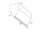
経皮吸収シート100は、皮膚に貼付することにより、皮膚内に薬剤を送達する。図1に示すように、経皮吸収シート100は、先細り形状のニードル部112と、ニードル部112と接続された錐台部114と、錐台部114と接続されたシート状のシート部116とを有している。先細り形状のニードル部112と錐台部114とにより針状凸部110が構成される。シート状とは、面積の広い主面に対して厚さが薄い、全体として平たい形状を意味し、主面が完全に平坦である必要はない。
The
シート部116の表面には複数個の錐台部114が形成される(図1においては一つの錐台部114のみ表示)。錐台部114は、2つの底面を有し、錐体面で囲まれた立体構造を有している。錐台部114の2つの底面のうち面積の広い底面(下底)がシート部116と接続される。錐台部114の2つの底面のうち面積の狭い底面(上底)がニードル部112と接続される。つまり、錐台部114の2つの底面のうち、シート部116と離れる方向にある底面の面積が小さくなっている。
A plurality of
ニードル部112は先細りの形状を有しており、ニードル部112は、面積の広い底面と、底面から離れた先端が最も狭い面積となる形状を有している。ニードル部112の面積の広い底面が、錐台部114の面積の狭い底面と接続されているので、ニードル部112は錐台部114と離れる方向に先細り形状となる。したがって、ニードル部112は錐台部114とで構成される針状凸部110は、全体としてシート部116から先端に向けて先細り形状を有している。シート部116の上には4〜2500本の複数の針状凸部110が設けられる。但し、この本数には限定されない。
The
図1において、錐台部114は円錐台の形状を有し、ニードル部112は円錐の形状を有している。ニードル部112の皮膚への挿入の程度に応じて、ニードル部112の先端の形状を、0.01μm以上50μm以下の曲率半径の曲面や、平坦面等に適宜変更することができる。
In FIG. 1, the
図2は、別の形状を有する針状凸部110を示している。図2においては、錐台部114は四角錐台の形状を有し、ニードル部112は四角錐の形状を有している。
FIG. 2 shows a needle-like
図3は、図1、図2に示される経皮吸収シート100の断面図である。図3(A)(B)に示されるように、経皮吸収シート100は薬剤を含む第1層120と、薬剤を含まない第2層122とにより構成されている。
FIG. 3 is a cross-sectional view of the
ここで、薬剤を含むとは、体表に穿刺した際に薬効を発揮する量の薬剤を含むことを意味する。また、薬剤を含まないとは、薬効を発揮する量の薬剤を含んでいないことを意味し、薬剤の量の範囲が、全く含まない0から薬効を発揮しない量までの範囲を含んでいる。薬剤を含む第1層120は針状凸部110の先端(ニードル部112の先端)に形成されている。第1層120を針状凸部110の先端に形成することにより、皮膚内に効率よく薬剤を送達することができる。以下、「所定量の薬剤を含む」を「薬剤を含む」と、「所定量の薬剤を含まない」を「薬剤を含まない」と必要に応じて称する場合がある。
Here, including a drug means including an amount of drug that exhibits a medicinal effect when puncturing the body surface. Moreover, the term “not containing a drug” means that the drug does not contain an amount of a drug that exhibits a medicinal effect, and the range of the amount of the drug includes a range from 0 that does not include a drug to an amount that does not exhibit a drug effect. The
ニードル部112の第1層120を除く部分には、薬剤を含まない第2層122が形成されている。錐台部114は第2層122により構成されている。シート部116は第2層122により構成されている。ニードル部112、錐台部114、及びシート部116を構成する第1層120、及び第2層122の配分は、適宜設定することができる。
A
シート部116の厚さTは、好ましくは10μm〜2000μmの範囲であり、より好ましくは10μm〜1000μmの範囲である。錐台部114とシート部116との接する底面(下底)の幅W1は、好ましくは100μm〜1500μmの範囲であり、より好ましくは100μm〜1000μmの範囲である。錐台部114とニードル部112との接する底面(上底)の幅W2は、好ましくは100μm〜1500μmの範囲であり、より好ましくは100μm〜1000μmの範囲である。幅W1と幅W2は、上記の数値範囲内で、W1>W2を満たすことが好ましい。
The thickness T of the
針状凸部110の高さHは、好ましくは100μm〜2000μmの範囲であり、より好ましくは200μm〜1500μmの範囲である。また、ニードル部112の高さH1と錐台部114の高さH2との比であるH1/H2は、好ましくは1〜10の範囲であり、より好ましくは1.5〜8の範囲である。また、錐台部114の高さH2は10μm〜1000μmの範囲であることが好ましい。
The height H of the needle-like
錐台部114の側面とシート部116の表面に平行な面とのなす角度αは、好ましくは10°〜60°の範囲であり、より好ましくは20°〜50°の範囲である。また、ニードル部112の側面と錐台部114の上底に平行な面とのなす角度βは、好ましくは45°〜85°の範囲であり、より好ましくは60°〜80°の範囲である。
The angle α formed between the side surface of the
角度βは角度αと等しくても良いが、角度βは角度α以上であることが好ましい。針状凸部110を皮膚に穿刺しやすくなるからである。
The angle β may be equal to the angle α, but the angle β is preferably equal to or greater than the angle α. This is because it becomes easier to puncture the needle-like
第一の実施形態では、図3(A)に示すように、少なくとも一つの針状凸部110は、シート部116から錐台部114に延びる空洞部124を有している。また図3(B)に示すように、少なくとも一つの針状凸部110は、シート部116から錐台部114を超えてニードル部112に延びる空洞部124を有している。
In a first implementation mode, as shown in FIG. 3 (A), at least one needle-
空洞部124は、シート部116の側に開口126を有し、針状凸部110内、即ち錐台部114に留まる空間、又は錐台部114を通過し、ニードル部112に留まる空間を意味し、空洞部124は針状凸部110内に完全に内包されず、また針状凸部110を貫通していない空間である。
The
空洞部124は、少なくとも錐台部114にまで延びている限り、その形状は特に限定されることはない。しかしながら、空洞部124の形状に関して、図3(A)に示すように空洞部124の全部がドーム形状、又は、図3(B)に示すように空洞部124の一部がドーム形状を有していることが好ましい。
The shape of the
ドーム形状とは、ある曲率半径を有する湾曲面を有する形状で、例えば半球状を例示できる。但し、半球状に限定されることなく、また、曲率半径が全体で同じである必要はない。 The dome shape is a shape having a curved surface having a certain radius of curvature, for example, a hemispherical shape. However, it is not limited to a hemispherical shape, and the radius of curvature does not have to be the same throughout.
空洞部124の全部がドーム形状とは、図3(A)に示すように空洞部124が湾曲面で構成されている場合を意味する。
The whole dome shape of the
空洞部124の一部がドーム形状とは、図3(B)に示すように空洞部124の先端部で、ニードル部112に含まれる部分が湾曲面で構成されている場合を意味する。先端部のドーム形状はニードル部112ではなく、錐台部114に存在する場合でも良い。
A part of the
空洞部124をドーム形状とすることで、穿刺時の衝撃や圧力に対して針状凸部110の構造を維持することができる。
By forming the
空洞部124をドーム形状とした場合、湾曲面を規定する曲率半径が10μm以上であることが好ましい。つまり、曲率半径10μm未満の角を持たない構造をしていることが好ましい。曲率半径を10μm以上とすることにより、応力が集中することを抑制することができ、針状凸部110が崩れてしまうことを抑制することができる。曲率半径は針状凸部110の大きさを考慮すると200μm以下であることが好ましい。
When the
空洞部124の大きさについて、特に限定されることはない。しかしながら、空洞部124の大きさは、空洞部124を有する針状凸部110の最も薄い部分の厚さTminが、シート部116の厚さT以下となる程度の大きさとすることが好ましい。シート部116の厚さTは、シート部116の平均厚さを意味する。厚さTminは、好ましくは、10μm〜500μmの範囲であり、より好ましくは10μm〜100μmの範囲である。最も薄い部分の厚さTminは、空洞部124から見て針状凸部110の肉厚の最も薄い部分の厚さである。
The size of the
また、針状凸部110に占める空洞部124の比率は、10%〜80%が好ましく、20〜60%がより好ましい。この範囲であれば、針状凸部110の強度を維持することができる。
Moreover, 10 to 80% is preferable and, as for the ratio of the
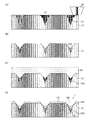
図4は、経皮吸収シートの薬剤が皮膚内に送達される状態を示す説明図である。図4(A)は経皮吸収シート100の針状凸部110を皮膚130に刺した直後の状態を示している。ニードル部112が皮膚130内に位置し、薬剤を含む第1層120が皮膚130内に配置される。空洞部124はシート部116から錐台部114の一部にまで延びている。
FIG. 4 is an explanatory view showing a state in which the medicine of the transdermal absorption sheet is delivered into the skin. FIG. 4A shows a state immediately after the needle-like
図4(B)は、経皮吸収シート100の針状凸部110を皮膚130に刺した後、数分間経過した状態を示している。ニードル部112を構成する第1層120が溶解し、第1層120に含まれる薬剤が皮膚130内に送達される。第1層120が溶解しているので、皮膚130に刺した直後と比較して、第1層120のサイズは小さくなっている。同様に、皮膚130内にある第2層122も溶解し、第2層122のサイズは小さくなっている。
FIG. 4B shows a state in which several minutes have elapsed after the needle-like
図4(C)は、図4(B)の状態から、数分間経過した状態を示している。ニードル部112を構成する第1層120、及び第2層122が更に溶解する。空洞部124に達するまで第2層122が溶解すると、第1層120、及び第2層122を含む針状凸部110がシート部116から分離するので、針状凸部110を皮膚130内に残すことができる。
FIG. 4C shows a state in which several minutes have elapsed from the state of FIG. The
針状凸部110の周囲全体が、皮膚130及び体液及びニードル溶解液と接触する。針状凸部110と皮膚130及び体液及びニードル溶解液との接触面積が大きくなるので、第2層122の溶解速度が促進され、第1層120の周囲全体が皮膚130及び体液及びニードル溶解液と接触するようになる。その結果、第1層120と皮膚130及び体液及びニードル溶解液との接触面積が大きくなるので、第1層120の溶解速度を促進することができる。
The entire circumference of the needle-like
空洞部124は、針状凸部110において、シート部116から少なくとも錐台部114に延びるように、つまり、図3(A)に示すように、錐台部114の一部に空洞部124が形成されていれば良い。さらに、空洞部124は、針状凸部110において、図3(B)に示すように、シート部116からニードル部112に延びるように、つまりニードル部112に形成されていることが好ましい。空洞部124をニードル部112に配置させることにより、第1層120と第2層122とを早期に分離した状態とできる。
The
また、空洞部124を有する針状凸部110の最も薄い部分の厚さTminが、シート部116の厚さT以下となる程度の大きさとすることが好ましい。厚さTminを上述の範囲とすることで、穿刺時にシート部の形状を保持することができ、穿刺圧を均一に保つことができるからである。
Further, it is preferable that the thickness T min of the thinnest portion of the needle-like
仮に、厚さTminよりもシート部116の厚さTが薄くなると、穿刺時にシート部116と皮膚が接触した場合、針状凸部110よりもシート部116が先に溶解してしまう可能性がある。穿刺時にシート部116の形状が保持されていないと、穿刺圧を均一に保つことは困難となる場合がある。
If the thickness T of the
一つの経皮吸収シート100に形成される複数の針状凸部110の少なくとも一つの針状凸部110が、シート部116から錐台部114に延びる空洞部124を有していれば良い。一つの経皮吸収シート100に錐台部114まで延びる空洞部124を含む針状凸部110と、空洞部124を含まない針状凸部110とを混在させることにより一つの経皮吸収シート100の薬剤の溶解速度を制御することができる。空洞部124を含む針状凸部110を、一つの経皮吸収シート100の特定の位置に配置しても良いし、又は一つの経皮吸収シート100のランダムな位置に配置してもよい。
It suffices that at least one needle-like
空洞部124を有する針状凸部110の数は、針状凸部110全体の数に対して20%〜100%の範囲が好ましい。この範囲であれば溶解速度の制御が容易となるからである。
The number of the needle-like
図5、図6は別の形状を有する針状凸部110を示している。図1と図5とに示される経皮吸収シート100と、図2と図6とに示される経皮吸収シート100は、錐台部114の形状が同一で、ニードル部112の形状がそれぞれ異なっている。図5と図6に示めされるニードル部112は、先細り針状部112Aと筒形状の胴体部112Bとを有している。先細り針状部112Aは面積の広い底面と、底面から離れた先端が最も狭い面積となる形状を有している。筒形状の胴体部112Bは、対向する2つの底面を有し、2つの底面の面積がほぼ同一である。針状部112Aの面積の広い方の底面と胴体部112Bの一方の底面とが接続されている。また、胴体部112Bの他方の底面と錐台部114の面積の狭い方の底面とが接続される。
5 and 6 show a needle-like
図5に示される針状部112Aは円錐の形状を有し、胴体部112Bは円柱の形状を有している。図6に示される針状部112Aは四角錐の形状を有し、胴体部112Bは四角柱の形状を有している。
The needle-
ニードル部112は胴体部112Bを有しているので、ニードル部112は錐台部114と離れる方向に一定の断面積を有する形状となる。ニードル部112の針状部112Aは、胴体部112Bから離れる方向に先細りの形状を有している。ニードル部112は全体として先細りの形状を有している。ニードル部112の皮膚への挿入の程度に応じて、ニードル部112の先端の形状を0.01μm以上50μm以下の曲率半径の曲面や、平坦面等に適宜変更することができる。
Since the
図7は、図5、図6に示される経皮吸収シート100の断面図である。図7(A),(B)に示されるように、経皮吸収シート100は薬剤を含む第1層120と、薬剤を含まない第2層122とにより構成されている。薬剤を含む第1層120は針状凸部110の先端(ニードル部112の先端)に形成されている。第1層120を針状凸部110の先端に形成することにより、皮膚内に効率よく薬剤を送達することができる。
FIG. 7 is a cross-sectional view of the
ニードル部112の第1層120を除く部分には、薬剤を含まない第2層122が形成されている。錐台部114は第2層122により構成されている。シート部116は第2層122により構成されている。ニードル部112、錐台部114、及びシート部116を構成する第1層120、及び第2層122の配分は、適宜設定することができる。
A
シート部116の厚さT、錐台部114の下底の幅W1、錐台部114の上底の幅W2、針状凸部110の高さH、及び錐台部114の高さH2を、図3に示す経皮吸収シート100と同様の長さにすることができる。ニードル部112の高さH1と錐台部114の高さH2との比であるH1/H2について、図3に示す経皮吸収シート100と同様の比にすることができる。
The thickness T of the
針状部112Aの高さH1Aと胴体部112Bの高さH1Bの比であるH1B/H1Aについて、H1B/H1Aは0.1〜4の範囲であり、好ましくは0.3〜2の範囲である。
Regarding H1B / H1A, which is the ratio of the height H1A of the needle-
錐台部114の側面とシート部116の表面に平行な面とのなす角度αは、10°〜60°の範囲であり、好ましくは20°〜50°の範囲である。また、針状部112Aの側面と胴体部112Bの底面に平行な面とのなす角度βは、45°〜85°の範囲であり、好ましくは60°〜80°の範囲である。
The angle α formed between the side surface of the
なお、角度βは角度α以上であることが好ましい。皮膚に対して針状凸部110を挿入しやすくなるからである。
The angle β is preferably equal to or larger than the angle α. This is because it becomes easier to insert the needle-like
第二の実施形態では、図7(A)に示すように、少なくとも一つの針状凸部110は、シート部116から錐台部114に延びる空洞部124を有している。また図7(B)に示すように、少なくとも一つの針状凸部110は、シート部116から錐台部114を超えてニードル部112に延びる空洞部124を有している。
In the second implementation embodiment, as shown in FIG. 7 (A), at least one needle-
空洞部124は、図3で説明したのと同様の形状を有している。また、空洞部124の形状、大きさに関しても図3に説明したのと同様である。空洞部124の全部がドーム形状であること、空洞部124の一部がドーム形状であることについても図3の説明と同様である。空洞部124を有する針状凸部110の最も薄い部分の厚さTminについても図3の説明と同様である。
The
本実施の形態では、図1,2,5,6に示す針状凸部110を有する経皮吸収シート100を示したが、経皮吸収シート100はこれらの形状に限定されない。
In the present embodiment, the
(モールド)
図8は、モールド(型)の作製の工程図である。
(mold)
FIG. 8 is a process diagram for producing a mold.
図8(A)に示すように、最初に、経皮吸収シートを製造するためのモールドを作製するための原版を作製する。 As shown in FIG. 8A, first, an original plate for producing a mold for producing a transdermal absorption sheet is produced.
この原版11の作製方法は2種類あり、1番目の方法は、Si基板上にフォトレジストを塗布した後、露光、現像を行う。そして、RIE(リアクティブイオンエッチング:Reactive Ion Etching)等のエッチングを行うことにより、原版11の表面に、経皮吸収シートの針状凸部と同形状である複数の凸部12をアレイ状に作製する。尚、原版11の表面に凸部12を形成するためにRIE等のエッチングを行う際には、Si基板を回転させながら斜め方向からのエッチングを行うことにより、凸部12を形成することが可能である。
There are two methods for producing the original 11, and in the first method, a photoresist is applied on a Si substrate, followed by exposure and development. Then, by performing etching such as RIE (Reactive Ion Etching), a plurality of
2番目の方法は、ステンレス、アルミニウム合金、Ni等の金属基板に、ダイヤモンドバイト等の切削工具を用いた加工により、原版11の表面に複数の凸部12をアレイ状に作製する方法がある。
The second method is a method in which a plurality of
次に、図8(B)に示すように、原版11を利用してモールド13を作製する。通常のモールド13の作製には、Ni電鋳などによる方法が用いられる。原版11は、先端が鋭角な円錐の形状又は角錐の形状(例えば四角錐)の形状の凸部12を有しているため、モールド13に形状が正確に転写され、モールド13を原版11から剥離することができる。しかも安価に製造することが可能な4つの方法が考えられる。
Next, as shown in FIG. 8B, a
1番目の方法は、原版11にPDMS(polydimethylsiloxane:ポリジメチルシロキサン、例えば、ダウコーニング社製シルガード184)に硬化剤を添加したシリコーン樹脂を流し込み、100℃で加熱処理し硬化した後に、原版11からモールド13を剥離する方法である。2番目の方法は、紫外線を照射することにより硬化する紫外線硬化樹脂を原版11に流し込み、窒素雰囲気中で紫外線を照射した後に、原版11からモールド13を剥離する方法である。3番目の方法は、ポリスチレンやPMMA(polymethyl methacrylate:ポリメチルメタクリレート)等のプラスチック樹脂を有機溶剤に溶解させたものを剥離剤の塗布された原版11に流し込み、乾燥させることにより有機溶剤を揮発させて硬化させた後に、原版11からモールド13を剥離する方法である。4番目の方法は、Ni電鋳により反転品を作成する方法である。
In the first method, a silicone resin with a curing agent added to PDMS (polydimethylsiloxane, eg, Sylgard 184 manufactured by Dow Corning) is poured into the
これにより、原版11の凸部12の反転形状である針状凹部15を2次元で配列したモールド13が作製される。このようにして作製されたモールド13を図8(C)に示す。原版11の凸部12は経皮吸収シートの針状凸部の形状と同じであるので、図8(C)に示すように、経皮吸収シートの針状凸部の反転型である複数の針状凹部を有するモールド13が製造される。尚、上記3つのいずれの方法においてもモールド13は、何度でも容易に作製することが可能である。
As a result, a
図9は、図8(C)で製造されたモールド13に枠14を設置した図である。図9(A)は、モールド13の表面の周囲に枠を設けた図である。図9(B)は、つなぎ合わされた複数のモールド13の周囲及び内部に枠14を設けた図である。枠14を設けることにより、機能性膜を所望の膜厚に形成する際、ポリマー樹脂の溶解液(以下、「ポリマー溶解液」ともいう)がモールド13の外に流れることを防止することができる。
FIG. 9 is a diagram in which a
このとき、モールド13と枠14との段差が50μm以上10mm以下とすることが好ましい。また、図9の型は、モールド13と枠14を分離できる構成であるが、一体型で構成することも可能である。分離型で構成した場合は、充填工程後の乾燥工程、剥離工程において、枠14を外すことが可能である。
At this time, the step between the
図9(B)に示すように、基板17上で、複数のモールド13同士を、接着剤を用いてつなぎ合わせる。そして、つなぎ合わされたモールド13の周囲、及び内部に枠14を設置する。
As shown in FIG. 9 (B), on the
図10はモールド13の部分拡大図である。針状凹部15は、モールド13の表面から深さ方向に狭くなるテーパ状の入口部15Aと、深さ方向に先細りの先端凹部15Bとを備えている。入口部15Aのテーパの角度α1は、経皮吸収シートの錐台部の側面とシート部とで構成される角度αと基本的に一致する。また、先端凹部15Bのテーパの角度β1は、ニードル部の側面と錐台部の上底とで構成される角度βと基本的に一致する。
FIG. 10 is a partially enlarged view of the
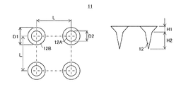
図11は、経皮吸収シートの製造方法を行う上で、より好ましいモールド複合体18の態様を示したものである。図11に示すように、モールド複合体18は、針状凹部15の先端に貫通孔15Cが形成されたモールド13と、モールド13の貫通孔15Cの側に貼り合わされ、気体は透過するが液体は透過しない材料で形成された気体透過シート19と、で構成される。貫通孔15Cにより、針状凹部15の先端は気体透過シート19を介して大気と連通する。針状凹部15の先端とは、モールド13の深さ方向に先細りなっている側を意味し、薬液、基材液が充填される側と反対側を意味する。
FIG. 11 shows a more preferable embodiment of the
このようなモールド複合体18を使用することで、針状凹部15に充填される経皮吸収材料溶液は透過せず、針状凹部15に存在する空気のみを針状凹部15から貫通孔15Cを介して抜くことができる。針状凹部15の形状を経皮吸収材料に転写する際の転写性が良くなり、よりシャープな針状凸部を形成することができる。
By using such a
貫通孔15Cの径D(直径)としては、1〜50μmの範囲が好ましい。この範囲とすることで、空気の抜けが容易となり、また、経皮吸収シートの針状凸部の先端部をシャープな形状とすることができる。気体は透過するが液体は透過しない材料で形成された気体透過シート19としては、例えばポアフロン(登録商標、住友電気工業株式会社)を好適に使用できる。
The diameter D (diameter) of the through
モールド13に用いる材料としては、弾性のある素材、金属製の素材を用いることができる。中でも弾性のある素材であることが好ましく、気体透過性の高い素材であることが更に好ましい。気体透過性の代表である酸素透過性は、1×10⁻¹²(mL/s・m・Pa)より大きいことが好ましく、1×10−10(mL/s・m・Pa)より大きいことがさらに好ましい。気体透過性を上記範囲とすることにより、モールド13の針状凹部15に存在する空気をモールド13側から追い出すことができる。欠陥の少ない経皮吸収シートを製造することができる。このような材料として、具体的には、シリコーン樹脂(例えば、シルガード184、1310ST)、紫外線硬化樹脂、プラスチック樹脂(例えば、ポリスチレン、PMMA(ポリメチルメタクリレート))を溶融、又は溶剤に溶解させたものなどを挙げることができる。これらの中でもシリコーンゴム系の素材は繰り返し加圧による転写に耐久性があり、且つ、素材との剥離性がよいため、好適に用いることができる。また、金属製の素材としては、Ni、Cu、Cr、Mo、W、Ir、Tr、Fe、Co、MgO、Ti、Zr、Hf、V、Nb、Ta、α−酸化アルミニウム,酸化ジルコニウム、ステンレス(スタバックス材)などやその合金を挙げることができる。枠14の材質としては、モールド13の材質と同様の材質のものを用いることができる。
As a material used for the
(ポリマー溶解液)
本実施形態に使用されるポリマー樹脂の溶解液であるポリマー溶解液について説明する。
(Polymer solution)
A polymer solution that is a polymer resin solution used in the present embodiment will be described.
本実施の形態では、薬剤を含むポリマー溶解液、又は薬剤を含む溶解液とは、所定量の薬剤を含有するポリマー溶解液、又は所定量の薬剤を含有する溶解液を意味する。また、薬剤を含まないポリマー溶解液、又は薬剤を含まない溶解液とは、所定量の薬剤を含有していないポリマー溶解液、又は所定量の薬剤を含有していない溶解液を意味する。 In the present embodiment, a polymer solution containing a drug or a solution containing a drug means a polymer solution containing a predetermined amount of drug or a solution containing a predetermined amount of drug. In addition, a polymer solution not containing a drug or a solution not containing a drug means a polymer solution that does not contain a predetermined amount of drug or a solution that does not contain a predetermined amount of drug.
また、薬剤を含むポリマー溶解液を薬液と称し、薬剤を含まないポリマー溶解液を基材液と称する場合がある。 Further, a polymer solution containing a drug may be referred to as a drug solution, and a polymer solution containing no drug may be referred to as a base material solution.
所定量の薬剤を含むか否かは、体表に穿刺した際に薬効を発揮できるか否かで判断される。したがって、所定量の薬剤を含むとは、体表に穿刺した際に薬効を発揮する量の薬剤を含むことを意味する。所定量の薬剤を含まないとは、薬効を発揮する量の薬剤を含んでいないことを意味し、薬剤の量の範囲が、全く含まない0から薬効を発揮しない量までの範囲を含んでいる。 Whether or not a predetermined amount of drug is contained is determined by whether or not the drug effect can be exhibited when the body surface is punctured. Therefore, the phrase “containing a predetermined amount of drug” means including an amount of drug that exhibits a medicinal effect when puncturing the body surface. The phrase “not containing a predetermined amount of drug” means that it does not contain an amount of drug that exhibits a medicinal effect, and the range of the amount of drug includes a range from 0 that does not include any drug to an amount that does not exhibit a medicinal effect. .
ポリマー溶解液に用いられる樹脂ポリマーの素材としては、生体適合性のある樹脂を用いることが好ましい。このような樹脂としては、グルコース、マルトース、プルラン、コンドロイチン硫酸、ヒアルロン酸ナトリウム、ヒドロキシエチルデンプン、ヒドロキシプロピルセルロースなどの糖類、ゼラチンなどのタンパク質、ポリ乳酸、乳酸グリコール酸共重合体などの生分解性ポリマーを使用することが好ましい。これらの中でもゼラチン系の素材は多くの基材と密着性をもち、ゲル化する材料としても強固なゲル強度を持つため、後述する剥離工程において、基材と密着させることができ、モールドから基材を用いてポリマーシートを剥離することができるので、好適に利用することができる。濃度は材料によっても異なるが、薬剤を含まないポリマー溶解液中に樹脂ポリマーが10〜50質量%含まれる濃度とすることが好ましい。また、溶解に用いる溶媒は、温水以外であっても揮発性を有するものであればよく、メチルエチルケトン、アルコールなどを用いることができる。そして、ポリマー樹脂の溶解液中には、用途に応じて体内に供給するための薬剤を共に溶解させることが可能である。薬剤を含むポリマー溶解液のポリマー濃度(薬剤自体がポリマーである場合は薬剤を除いたポリマーの濃度)としては、0〜40質量%であることが好ましい。 As a material of the resin polymer used for the polymer solution, it is preferable to use a biocompatible resin. Such resins include glucose, maltose, pullulan, chondroitin sulfate, sodium hyaluronate, saccharides such as hydroxyethyl starch and hydroxypropylcellulose, proteins such as gelatin, biodegradable such as polylactic acid and lactic acid glycolic acid copolymer. It is preferred to use a polymer. Among these materials, gelatin-based materials have adhesive properties with many substrates, and have strong gel strength as a material to be gelled. Since a polymer sheet can be peeled off using a material, it can be suitably used. Although the concentration varies depending on the material, it is preferable that the concentration is such that 10 to 50% by mass of the resin polymer is contained in the polymer solution not containing the drug. Further, the solvent used for dissolution may be volatile even if it is other than warm water, and methyl ethyl ketone, alcohol, or the like can be used. And in the solution of polymer resin, it is possible to dissolve together the medicine for supplying into the body according to the use. The polymer concentration of the polymer solution containing the drug (when the drug itself is a polymer, the concentration of the polymer excluding the drug) is preferably 0 to 40% by mass.
ポリマー溶解液の調製方法としては、水溶性の高分子(ゼラチンなど)を用いる場合は、水溶性粉体を水に溶解し、溶解後に薬剤を添加してもよいし、薬剤が溶解した液体に水溶性高分子の粉体を入れて溶かしても良い。水に溶解しにくい場合、加温して溶解してもよい。温度は高分子材料の種類により、適宜選択可能であるが、約60℃以下の温度で加温することが好ましい。ポリマー樹脂の溶解液の粘度は、薬剤を含む溶解液では100Pa・s以下であることが好ましく、より好ましくは10Pa・s以下とすることが好ましい。薬剤を含まない溶解液では2000Pa・s以下であることが好ましく、より好ましくは1000Pa・s以下とすることが好ましい。ポリマー樹脂の溶解液の粘度を適切に調整することにより、モールドの針状凹部に容易に溶解液を注入することが容易となる。例えば、ポリマー樹脂の溶解液の粘度は、細管式粘度計、落球式粘度計、回転式粘度計、又は振動式粘度計で測定することができる。 As a method for preparing a polymer solution, when a water-soluble polymer (such as gelatin) is used, a water-soluble powder may be dissolved in water, and a drug may be added after the dissolution. A water-soluble polymer powder may be added and dissolved. If it is difficult to dissolve in water, it may be dissolved by heating. The temperature can be appropriately selected depending on the type of the polymer material, but it is preferable to heat at a temperature of about 60 ° C. or lower. The viscosity of the polymer resin solution is preferably 100 Pa · s or less, more preferably 10 Pa · s or less, in the case of a solution containing a drug. In the case of a solution that does not contain a drug, it is preferably 2000 Pa · s or less, more preferably 1000 Pa · s or less. By appropriately adjusting the viscosity of the polymer resin solution, it becomes easy to inject the solution into the needle-shaped recess of the mold. For example, the viscosity of the polymer resin solution can be measured with a capillary tube viscometer, falling ball viscometer, rotary viscometer, or vibration viscometer.
(薬剤)
ポリマー溶解液に含有させる薬剤は、生理活性を有する物質であればよく、特に限定されない。薬剤として、ペプチド、タンパク質、核酸、多糖類、ワクチン、医薬化合物、又は化粧品成分から選択することが好ましい。また、医薬化合物は水溶性低分子化合物に属するものであることが好ましい。ここで、低分子化合物とは数百から数千の分子量の範囲の化合物である。
(Drug)
The drug contained in the polymer solution is not particularly limited as long as it has a physiological activity. The drug is preferably selected from peptides, proteins, nucleic acids, polysaccharides, vaccines, pharmaceutical compounds, or cosmetic ingredients. Moreover, it is preferable that a pharmaceutical compound belongs to a water-soluble low molecular weight compound. Here, the low molecular compound is a compound having a molecular weight in the range of several hundred to several thousand.
(経皮吸収シートの製造方法)
本実施の形態の経皮吸収シートの製造方法は、図12に示すように、薬液充填工程と、薬液乾燥工程と、基材液充填工程と、基材液乾燥工程と、剥離工程との少なくとも5つの工程をこの順で備えている。
(Method for producing transdermal absorption sheet)
As shown in FIG. 12, the method for producing a transdermal absorption sheet of the present embodiment includes at least a chemical liquid filling step, a chemical liquid drying step, a base liquid filling step, a base liquid drying step, and a peeling step. Five steps are provided in this order.
(薬液充填工程)
モールド13を用いた経皮吸収シートの製造方法について説明する。図13(A)に示すように、2次元配列された針状凹部15を有するモールド13が、基台20の上に配置される。モールド13には、5×5の2次元配列された、2組の複数の針状凹部15が形成されている。薬剤を含むポリマー溶解液である薬液22を収容する送液タンク30と、送液タンク30に接続される配管32と、配管32の先端に接続されたノズル34と、を有する液供給装置36が準備される。薬液22はノズル34の先端から吐出される。
(Chemical solution filling process)
A method for producing a transdermal absorption sheet using the
図14はノズルの先端部の概略斜視図を示している。図14に示すように、ノズル34は、先端側に平坦面であるリップ部34Aと、スリット形状の開口部34Bと、リップ部34Aに沿って開口部34Bから離れる方向に広がる2つの傾斜面34Cと、を備えている。スリット形状の開口部34Bにより、例えば、1列を構成する複数の針状凹部15に同時に、薬液22を充填することが可能となる。開口部34Bの大きさ(長さと幅)は、一度に充填すべき針状凹部15の数に応じて適宜選択される。
FIG. 14 shows a schematic perspective view of the tip of the nozzle. As shown in FIG. 14, the
開口部34Bの長さを長くすることで、より多くの針状凹部15に一度に薬液22を充填することができる。これにより生産性を向上させることが可能となる。
By increasing the length of the
図15は別のノズルの先端部の概略斜視図を示している。図15に示すように、ノズル34は、先端側に平坦面であるリップ部34Aと、2つのスリット形状の開口部34Bと、リップ部34Aに沿って開口部34Bから離れる方向に広がる2つの傾斜面34Cと、を備えている。2つの開口部34Bにより、例えば、2列を構成する複数の針状凹部15に同時に、薬剤を含む薬液22を充填することが可能となる。
FIG. 15 shows a schematic perspective view of the tip of another nozzle. As shown in FIG. 15, the
ノズル34に用いる材料としては、弾性のある素材、金属製の素材を用いることができる。例えば、テフロン(登録商標)、ステンレス鋼、チタン等が挙げられる。
As a material used for the
図13(B)を参照して充填工程を説明する。図13(B)に示すように、ノズル34の開口部34Bが針状凹部15の上に位置調整される。薬液22を吐出するノズル34がモールド13に押し付けられるので、ノズル34のリップ部34Aとモールド13の表面とは接触している。液供給装置36から薬液22がモールド13に供給され、ノズル34の開口部34Bから薬液22が針状凹部15に充填される。本実施形態では、1列を構成する複数の針状凹部15に薬液22が同時に充填される。ただし、これに限定されず、針状凹部15に一つずつ充填することができる。また、図15に示すノズル34を使用することで、複数列を構成する複数の針状凹部15に対し、複数列毎に薬液22を同時に充填することもできる。
The filling process will be described with reference to FIG. As shown in FIG. 13B, the position of the
モールド13が気体透過性を有する素材で構成される場合、モールド13の裏面から吸引することで薬液22を吸引でき、針状凹部15内への薬液22の充填を促進させることができる。
When the
図13(B)の充填工程に次いで、図13(C)に示すように、ノズル34のリップ部34Aとモールド13の表面とを接触させながら、開口部34Bの長さ方向と垂直方向に液供給装置36を相対的に走査させている。ノズル34をモールド13の上を走査させ、薬液22が充填されていない針状凹部15にノズル34を移動させる。ノズル34の開口部34Bが針状凹部15の上に位置調整される。本実施の形態では、ノズル34を走査させる例で説明したが、モールド13を走査させてもよい。
After the filling step of FIG. 13B, as shown in FIG. 13C, the liquid is applied in a direction perpendicular to the length direction of the
ノズル34のリップ部34Aとモールド13の表面とを接触させてノズル34をモールド13の上を走査させているので、ノズル34がモールド13の針状凹部15以外の表面に残る薬液22を掻き取ることができる。薬剤を含む薬液22をモールド13の針状凹部15以外に残らないようにすることができる。また、本実施の形態では、ノズル34は、傾斜面34Cを矢印で示す走査方向に対して直交する位置となるよう配置されている。したがって、ノズル34はモールド13の上をスムーズに走査させることができる。
Since the
モールド13へのダメージを減らし、モールド13の圧縮による変形をできるだけ抑制するため、走査される際のノズル34のモールド13への押し付け程度を制御することが好ましい。例えば、ノズル34のモールド13への押し付け力や、ノズル34のモールド13への押し込み距離を制御することが好ましい。また、薬液22がモールド13の針状凹部15以外に残らないようにするため、モールド13もしくはノズル34の少なくとも一方がフレキシブルな弾性変形する素材であることが望ましい。
In order to reduce damage to the
図13(B)の充填工程と、図13(C)の移動工程とを繰り返すことで、5×5の2次元配列された針状凹部15に薬液22が充填される。5×5の2次元配列された針状凹部15に薬液22が充填されると、隣接する5×5の2次元配列された針状凹部15に液供給装置36を移動し、図13(B)の充填工程と、図13(C)の移動工程とを繰り返す。隣接する5×5の2次元配列された針状凹部15にも薬液22が充填される。
By repeating the filling step in FIG. 13B and the moving step in FIG. 13C, the
上述の充填工程と走査工程について、(1)ノズル34を走査させながら薬液22を針状凹部15に充填する態様でもよいし、(2)ノズル34の走査中に針状凹部15の上でノズル34を一旦静止して薬液22を充填し、充填後にノズル34を再度走査させる態様でもよい。充填工程と走査工程との間、ノズル34のリップ部34Aがモールド13の表面に押し付けられている。液供給装置36から吐出される薬液22の量は、充填されるモールド13の複数の針状凹部15の総体積と等しい量とすることが好ましい。薬液22をモールド13の針状凹部15以外の表面に残らないようにし、薬剤のロスを低減することができる。
With respect to the above-described filling step and scanning step, (1) the
図16は、薬液22を針状凹部15に充填中におけるノズル34の先端とモールド13との部分拡大図である。図16に示すように、ノズル34内に加圧力P1を加えることで、針状凹部15内へ薬液22を充填するのを促進することができる。さらに、針状凹部15内へ薬液22を充填する際、ノズル34をモールド13の表面に接触させる押し付け力P2を、ノズル34内の加圧力P1以上とすることが好ましい。押し付け力P2≧加圧力P1とすることにより、薬液22が針状凹部15からモールド13の表面に漏れ出すのを抑制することができる。
FIG. 16 is a partially enlarged view of the tip of the
図17は、ノズル34の移動中における、ノズル34の先端とモールド13との部分拡大図である。ノズル34をモールド13に対して相対的に走査する際、ノズル34をモールド13の表面に接触させる押し付け力P3を、充填中のノズル34をモールド13の表面に接触させる押し付け力P2より小さくすることが好ましい。モールド13へのダメージを減らし、モールド13の圧縮による変形を抑制するためである。
FIG. 17 is a partially enlarged view of the tip of the
ノズル34のリップ部34Aはモールド13の表面に対して平行であることが好ましい。ノズル34の取り付け部に関節駆動機構を設けることにより、ノズル34の姿勢を制御してもよい。
The
モールド13の表面形状に合わせてZ軸方向にノズル34を駆動して、ノズル34のモールド13への押し付け力及び/又は押し込み距離を制御することが好ましい。図18は、押し付け力、及び/又は押し込み距離を制御することができる薬液充填装置48の概略構成図である。薬液充填装置48は、薬液を貯留する送液タンク30と送液タンク30に取り付けられたノズル34とを有する液供給装置36と、送液タンク30とノズル34とをZ軸方向に駆動するZ軸駆動部50と、モールド13を載置するための吸引台52と、吸引台52をX軸方向に駆動するX軸駆動部54と、上記装置を支持する架台56と、制御システム58と、を有している。
It is preferable to control the pressing force and / or the pressing distance of the
押し付け力を一定に制御する場合について説明する。所望の押し付け力となるZ座標までZ軸駆動部50によりノズル34をモールド13に近づける。モールド13に接触したノズル34をX軸駆動部54により走査させながら、押し付け力が一定となるようにZ軸座標を制御しつつ薬液22を吐出する。接触圧力測定の方式は特に限定はしないが、例えば、各種ロードセルを、例えば吸引台52の下に、又は吸引台52に代えて用いることができる。ロードセルとは厚み方向に圧縮する力を測定できる測定器具を意味する。押し付け力は、モールド13に対して1〜1000kPaの範囲内の任意の圧力で一定に制御可能であることが好ましい。
A case where the pressing force is controlled to be constant will be described. The
押し込み距離を一定に制御する場合について説明する。ノズル34を接触する前に、モールド13の表面形状をあらかじめ測定する。モールド13に接触したノズル34をX軸駆動部54により走査させながら、モールド13の表面形状に対して所望の押し込み距離になるようにZ軸座標をオフセットさせた値をZ軸駆動部50にフィードバックしつつ薬液22を吐出する。
A case where the pushing distance is controlled to be constant will be described. Before contacting the
形状測定の方式は特に限定はしないが、例えば、非接触式のレーザー変位計60などの光学測定機器、接触式の触針式段差計等を用いることができる。さらに、ノズル34のスリット方向の姿勢をモールド13の表面形状に合わせて制御してもよい。押し込み距離は、モールド13の厚みに対して1〜15%の範囲で制御されることが好ましい。モールド13の形状に合わせてノズル34とモールド13と距離を、Z軸駆動部50によりZ軸方向に制御しながら動作することで、圧縮変形率が均一化され、充填量精度を向上できる。
The method of shape measurement is not particularly limited, and for example, an optical measuring instrument such as a non-contact type laser displacement meter 60, a contact type stylus type step gauge, or the like can be used. Further, the posture of the
押し付け力、及び押し込み距離の制御に関して、押し込み距離が小さい場合は押し付け力を制御することが好ましく、押し込み距離が大きい場合は、押し込み距離を直接制御することが好ましい。 Regarding the control of the pressing force and the pressing distance, it is preferable to control the pressing force when the pressing distance is small, and it is preferable to directly control the pressing distance when the pressing distance is large.
図19は、ノズル内の液圧と薬剤を含む溶解液の供給との関係を示す説明図である。図19に示すように薬液22の供給は、ノズル34が針状凹部15の上に位置する前から開始される。薬液22を針状凹部15に確実に充填するためである。5×5で構成される複数の針状凹部15への充填が完了するまで、薬液22はモールド13に連続して供給される。ノズル34が5列目の針状凹部15の上に位置する前に、薬液22をモールド13に供給するのを停止する。薬液22が針状凹部15からあふれ出るのを防止できる。ノズル34内の液圧に関して、薬液22の供給が開始されると、ノズル34が針状凹部15に位置しない領域では高くなる。一方、ノズル34が針状凹部15の上に位置すると、薬液22が針状凹部15に充填され、ノズル34内の液圧が低くなるので、液圧の変動が繰り返される。
FIG. 19 is an explanatory diagram showing the relationship between the fluid pressure in the nozzle and the supply of a solution containing a drug. As shown in FIG. 19, the supply of the
5×5で構成される複数の針状凹部15への充填が完了すると、ノズル34は、隣接する5×5で構成される複数の針状凹部15へ移動される。液供給に関して、隣接する5×5で構成される複数の針状凹部15へ移動する際、薬液22の供給を停止するのが好ましい。5列目の針状凹部15から次の1列目の針状凹部15までは距離がある。その間をノズル34が走査される間、薬液22を供給し続けると、ノズル34内の液圧が高くなりすぎる場合がある。その結果、ノズル34から薬液22がモールド13の針状凹部15以外に流れ出る場合があり、これを抑制するため薬液22の供給を停止するのが好ましい。
When the filling of the plurality of needle-
薬液充填を行う際には、ノズル34の先端をクリーニングしてから使用することが好ましい。充填前にノズル34のリップ部34Aの表面に付着物があると、薬液22の充填量の精度が低下してしまうためである。クリーニングは、不織布によるワイプが一般的である。ワイプの際に、不織布を水や溶剤などで浸潤させると効果的にクリーニングできる。薬液22の充填後、ノズル34をモールド13から離す際に、モールド13の表面に薬液が残留する可能性がある。針状凹部15への充填が完了後、ノズル34の開口部34Bから薬液を吸引するサックバック制御を行うことで、吐出余剰分の薬液22を吸い上げ、モールド13の表面への液残りを低減することもできる。
When filling the chemical solution, it is preferable to use after cleaning the tip of the
薬液充填工程について、図11に示すモールド複合体18を利用し、貫通孔15C側から吸引して、薬液22を針状凹部15内に充填させることができる。特に、薬液22に気泡が取り込まれると、薬剤の含有量にバラつきが生じ、好ましくないからである。
About the chemical | medical solution filling process, it can attract | suck from the through-
薬液22の針状凹部15への充填が完了すると、薬液乾燥工程、基材液充填工程、基材液乾燥工程、剥離工程へと進む。
When the filling of the
図20(A)に示すように、薬液充填工程にてモールド13の針状凹部15に薬液22をノズル34から充填する。薬液充填工程は上述した方法で実施される。
As shown in FIG. 20 (A), the
(薬液乾燥工程)
図20(B)に示すように、薬液乾燥工程では、薬液22を乾燥し、固化させることで、薬剤を含む第1層120を針状凹部15内に形成する。
(Chemical solution drying process)
As shown in FIG. 20B, in the chemical liquid drying step, the
薬液乾燥工程は、モールド13の針状凹部15に充填された薬液22を乾燥し、薬剤を含む第1層120を針状凹部15の先端に局在させる工程である。
The chemical solution drying step is a step of drying the
また、薬液乾燥工程の温湿度条件を制御して乾燥速度を最適化することにより、針状凹部15のモールド13の壁面に薬液22が固着するのを低減することができ、乾燥により薬液22が針状凹部15の先端に集まりながら乾燥が進む。例えば、温度23℃、相対湿度40〜60%RHの環境下では、乾燥速度が速いため針状凹部15のモールド13壁面に薬液22が固着し、薬液22を針状凹部15の先端に局在させることが難しくなる場合がある。
Further, by controlling the temperature and humidity conditions in the chemical solution drying process and optimizing the drying speed, it is possible to reduce the adhesion of the
薬液乾燥工程を温度1℃〜10℃の環境下で行うことにより、薬液22の乾燥速度は遅くできる。したがって、モールド13の壁面に薬液22が固着することなく、薬液22を針状凹部15の先端に局在させることができる。温度1℃〜10℃の環境下の薬液乾燥工程において、湿度が高い場合、薬液22の乾燥速度が遅くなるため、生産性の低下をもたらす。そこで、薬液乾燥工程を温度1℃〜10℃の環境下で行う場合、好ましくは相対湿度1〜59%の環境下とし、より好ましくは21〜39%の環境下とする。温度1℃〜10℃で、相対湿度1〜59%の温湿度範囲の環境下であれば、針状凹部15の先端への薬液22の局在化と生産性を両立することができる。
By performing the chemical solution drying step in an environment at a temperature of 1 ° C. to 10 ° C., the drying speed of the
相対湿度1〜59%の環境下にするために、例えば、湿度調整機能を有する恒温室、又は恒温槽内で薬液乾燥工程を行うことが好ましい。 In order to obtain an environment with a relative humidity of 1 to 59%, for example, it is preferable to perform the chemical solution drying step in a thermostatic chamber or a thermostatic chamber having a humidity adjusting function.
薬液乾燥工程における薬液22の乾燥は無風状態で行うことが好ましい。不均一な風が薬液22に直接当たると乾燥ムラが生じる。強く風が当たる部分は乾燥速度が上昇し、モールド13の壁面への薬液22の固着が発生し、針状凹部15の先端への薬液22が局在化することを妨げる可能性があるからである。
It is preferable to dry the
無風状態での乾燥実現するため、例えば、風防を設置することが好ましい。風防は、モールド13に直接風が当たらないように設置される。風防として、蓋、庇、衝立、囲いなどの物理的障害物を設置する方法が簡便であるので好ましい。また、風防を設置する際は、モールド13の設置空間が密閉状態にならないように通気口等を確保することが好ましい。密閉状態にしてしまうと密閉空間の水蒸気が飽和し、薬液22の乾燥が進行しなくなる可能性がある。通気口は蒸気の出入りができれば好ましく、風防内の気流を安定化するには水蒸気透過性のフィルムなどで通気口を覆うことが更に好ましい。なお、乾燥時間は、針状凹部15の形状、針状凹部15の配置や数、薬剤の種類、薬液22の充填量や濃度、などを考慮して適宜調整される。
In order to achieve drying in a windless state, for example, it is preferable to install a windshield. The windshield is installed so that the wind does not directly hit the
無風状態とは、風が全くない状態に加えて、風速が0.5m/s以下である場合をいう。この範囲であれば、乾燥ムラがほとんど生じないからである。 The windless state refers to a case where the wind speed is 0.5 m / s or less in addition to a state where there is no wind. This is because within this range, drying unevenness hardly occurs.
薬液乾燥工程では、薬液22を乾燥させることにより固化し、薬液22を充填した際の状態よりも縮小させている。これにより、剥離工程において、モールド13の針状凹部15から第1層120を容易に剥離することが可能となる。
In the chemical solution drying step, the
(基材液充填工程)
次に、図20(C)に示すように、薬剤を含む第1層120の上に薬剤を含まないポリマー溶解液である基材液24をディスペンサーにより塗布し、基材液24を針状凹部15に充填する。針状凹部15の空間を超える量の基材液24は充填される。ディスペンサーによる塗布に代えて、バー塗布やスピン塗布、スプレーなどによる塗布などを適用することができる。
(Substrate liquid filling process)
Next, as shown in FIG. 20 (C), a
基材液24の量が多すぎると、次の基材液乾燥工程における乾燥収縮により形成される空洞部124が錐台部114まで延びない場合がある。したがって、基材液24の組成、濃度、粘度、乾燥速度などを考慮し、所望の空洞部124が得られる基材液24の塗布量をあらかじめ求めておくことが好ましい。
If the amount of the
適切な塗布量で基材液24を乾燥させることにより、空洞部124をドーム形状とすることができ、また、空洞部124を有する針状凸部110の最も薄い部分の厚さTminを、シート部116の厚さT以下とすることができる(図3,7)。
By drying the
(基材液乾燥工程)
次に、図20(D)に示すように、基材液乾燥工程において、基材液24を乾燥させて薬剤を含まない第2層122を第1層120の上に形成することで、シート部116、及び錐台部114とニードル部112とから構成される針状凸部110を形成する。この基材液乾燥工程で、基材液24を乾燥収縮することにより針状凸部110にシート部116から錐台部114に延びる空洞部124を形成し、ポリマーシート1(モールド13から剥離する前の経皮吸収シート100)を製造する。
(Substrate liquid drying process)
Next, as shown in FIG. 20D, in the base material liquid drying step, the
基材液乾燥工程においては、針状凸部110にシート部116から錐台部114を超えてニードル部112に延びる空洞部124を形成することもできる。
In the base material liquid drying step, a
本実施形態において、発明者は、針状凸部110に空洞部124を形成する方法を鋭意検討した。基材液乾燥工程において、基材液24を乾燥収縮することにより空洞部124を形成することができることを見出した。特に、空洞部124を形成する際に、基材液24を緩やかに乾燥させることが空洞部124の形成に適していること見出した。緩やかな乾燥は、例えば、高湿、低温又は低風速環境下で乾燥することにより実現することが可能である。
In the present embodiment, the inventors diligently studied a method for forming the
基材液24を緩やかに乾燥させることにより、(1)基材液の表面が皮バリ(表面が乾燥して皮を張る現象)してシート部116に皺がよったり、(2)ニードル部112の基材液が急激に乾燥収縮することによりモールド13の表面から基材液24がはがれて針状凸部110の先端形状がくずれたりし、良好な針形状が得られなくなることを抑制することができる。
By slowly drying the
特に、低温環境にすることにより、空洞部124の形成と、第1層120から第2層122への薬剤の拡散の抑制とを達成することが可能となる。
In particular, the formation of the
本実施の形態では、基材液乾燥工程が温度1℃〜30℃の環境下で行われることが好ましい。基材液乾燥工程を温度30℃より大きい環境下にすると、急速に基材液24が乾燥し、基材液表面の皮バリやニードル部の針形状不良を引き起こしてしまう可能性がある。
In this Embodiment, it is preferable that a base-material liquid drying process is performed in the environment of
針状凹部15の先端部には薬剤を含む第1層120が固化した状態で存在する。基材液24を充填した際に空洞部124が存在しなければ、第1層120に基材液24が浸透し、第1層120の基材液24への拡散を招く問題がある。この第1層120の拡散が錐台部114やシート部116に到達すると、穿刺時に薬剤は皮膚内に浸透せず、ロスになってしまう。本実施の形態では空洞部124が存在するので、結果的に錐台部114及び/又はニードル部112内に存在する基材液体積が減少し、乾燥前に拡散した薬剤は空洞部124の形成に伴い針状凹部15の先端に集まる。更には、乾燥の過程で第1層120が拡散する基材液24の通り道を大幅に狭めることができるため、大部分の第1層120の成分をニードル部112内に留まらせることができる。したがって、基材液24の第1層120への浸透を抑制でき、結果として第1層120が基材液24に拡散するのを抑制することができる。
The
本実施の形態において、温度と相対湿度とは以下の環境であることが好ましい。
温度20℃より大きく30℃以下では、相対湿度40%RH〜80%RHが好ましい。温度10℃より大きく20℃以下では、相対湿度35%RH〜80%RHが好ましい。温度1℃以上10℃以下では、相対湿度30%RH〜80%RHが好ましい。また、乾燥を実施する際の風速は、0m/s〜5m/sが好ましい。
In the present embodiment, the temperature and the relative humidity are preferably the following environments.
When the temperature is higher than 20 ° C and lower than 30 ° C, the relative humidity is preferably 40% RH to 80% RH. When the temperature is higher than 10 ° C and lower than 20 ° C, the relative humidity is preferably 35% RH to 80% RH. When the temperature is 1 ° C. or higher and 10 ° C. or lower, the relative humidity is preferably 30% RH to 80% RH. In addition, the wind speed at the time of drying is preferably 0 m / s to 5 m / s.
空洞部124を形成するには、乾燥過程で基材液24を流動させる必要がある。基材液24の表層の含水率を流動する程度に調整する必要がある。一般的に、物質の平衡含水率は、一定の気温においては周囲の水蒸気圧が高くなると増加し、一定の水蒸気圧においては気温が高くなると減少する。一方で、低温下では水分の蒸発速度が遅くなるため、基材液24内の水分拡散の方が優位となり、平衡含水率が低くても基材液24は流動する。以上に鑑みて鋭意検討した結果、上記条件の範囲内で環境を制御することにより空洞部124を成形できることを見出した。なお、乾燥時間は基材液の量や組成や濃度、周囲の温湿度や風の有無などに応じて変化する。
In order to form the
所望の温湿度環境下にするために、例えば、温湿度調整機能を有する恒温室、又は恒温槽内で基材液乾燥工程を行うことが好ましい。 In order to obtain a desired temperature and humidity environment, for example, it is preferable to perform the base material liquid drying step in a thermostatic chamber or a thermostatic chamber having a temperature and humidity adjusting function.
基材液乾燥工程では、基材液24が乾燥により体積が縮小する。基材液24が乾燥中にモールド13に密着していれば体積の縮小はシートの膜厚方向に起こり、膜厚が薄くなる。この現象を利用して、錐台部114及びニードル部112に空洞部124を形成することができる。
In the substrate liquid drying step, the volume of the
なお、低温環境は、基材液乾燥工程全体を低温化することで実現することができる。しかしながら、少なくともモールド13を冷却するだけでも針状凸部110に空洞部124を形成することを発明者は見出した。モールド13の冷却温度は、基材液の組成や濃度、周囲の温湿度や風の有無などに応じて適宜設定するが、温度1℃〜20℃が好ましく、温度1℃〜15℃がさらに好ましい。モールド13の冷却温度は、モールド13を直接測定することにより求めることができる。
The low temperature environment can be realized by lowering the temperature of the entire substrate liquid drying process. However, the inventor has found that the
基材液乾燥工程を温度1℃以上20℃以下の環境下にするために、例えば、基材液乾燥工程を恒温室、又は恒温槽内に設置してもよい。 In order to bring the base material liquid drying step into an environment having a temperature of 1 ° C. or higher and 20 ° C. or lower, for example, the base material liquid drying step may be installed in a thermostatic chamber or a thermostatic bath.
また、基材液乾燥工程において、例えば、チラーやペルテェ素子などを使用して基材液24が液体状態で滞留するモールド13のみを局所的に冷却をすることが可能である。
In the base material liquid drying step, for example, it is possible to locally cool only the
本実施の形態の経皮吸収シートの製造方法によれば、空洞部124を安定的に形成することができる。また、基材液乾燥工程で生じる、急速乾燥に起因する基材液表面の皮バリやニードル部112の針形状不良を抑制することができる。また、空洞部124の存在により、薬剤を含む第1層120が薬剤を含まない第2層122の側に拡散するのを抑制することができる。
According to the method for manufacturing a percutaneous absorption sheet of the present embodiment, the
また、空洞部124は第2層122の中に留まることが好ましい。薬剤を含む第1層120を針状凹部15の先端部に維持することができるので好ましい。
The
空洞部124を形成する方法として基材液乾燥工程で実施する場合について説明したが、特に、限定されない。例えば、空洞部124を形成するための別の方法として、(1)モールド13の針状凹部15の開口側から空洞部124の形状に応じた型を当てた状態で乾燥する方法や、(2)乾燥後にシート部116の側から針状凸部110の錐台部114を削ることによって空洞部124を形成する方法、などが挙げられる。
If implemented in base liquid drying process as a method of forming a
なお、乾燥中に基材液24がモールド13から剥離してしまうと、ポリマーシート1が面方向にも収縮するため歪んでしまったり、カールしたりする場合がある。また、針状凹部15内の基材液24が十分に乾燥していない状態でポリマーシート1がモールド13から剥離してしまうと、ポリマーシート1の針状凸部の形状が折れたり、曲がったりする不良が発生しやすい。このため、乾燥中にポリマーシート1がモールド13から剥離しないことが好ましい。また、カールを抑制するためにポリマーシート1の裏面(針状凸部の形成される面と反対の面)に針状凸部のある表面と同程度に収縮する層を形成してもよい。例えば、裏面側にも表面側と同じポリマー溶解液を塗布し、カール抑制の効果を予め確認した膜厚となるように層形成する。
If the
(剥離工程)
ポリマーシート1をモールド13から剥離する方法は限定されるものではない。剥離の際に針状凸部が曲がったり折れたりしないことが望まれる。具体的には、図21に示すように、ポリマーシート1の上に、粘着性の粘着層が形成されているシート状の基材40を付着させた後、端部から基材40をめくるように剥離を行うことができる。ただしこの方法では針状凸部が曲がる可能性がある。そのため、図22に示すように、ポリマーシート1の裏面に吸盤(不図示)を設置し、エアーで吸引しながら垂直に引き上げる方法を適用することができる。ポリマーシート1をモールド13から剥離することにより、経皮吸収シート100を製造する。
(Peeling process)
The method for peeling the
通常、本実施の形態のように、アスペクト比の高い針状凸部の構造物をモールド13から剥離する場合では、接触面積が大きいことから、強い応力が加わる。針状凸部である微小針が破壊され、モールド13から剥離されることなく針状凹部15内に残存し、作製される経皮吸収シートは欠陥を有するものとなる。本実施の形態においては、モールド13を構成する材料を、剥離が非常にしやすい材料により構成することが好ましい。また、モールド13を構成する材料を弾性が高く柔らかい材料とすることにより、剥離する際における微小針に加えられる応力を緩和することができる。
Normally, when a structure having a needle-like convex portion having a high aspect ratio is peeled off from the
(脱気工程)
薬液充填工程の前、及び/又は基材液充填工程の前、薬液22、及び/又は基材液24を脱気することが好ましい。脱気することにより、モールド13の針状凹部15に充填する前に、薬液22、及び基材液24に含まれる気泡を除去することができる。例えば、脱気工程では100μm〜数mmの直径の気泡が除去される。薬液22、及び基材液24の少なくとも一方を脱気することで、ポリマー溶解液に気泡を溶解させることを促進することができる。
(Deaeration process)
It is preferable to deaerate the
脱気方法として、例えば、(1)薬液22を1〜15分間減圧環境下に晒す方法、(2)薬液22を貯留する容器を5〜10分間超音波振動させる方法、(3)薬液22を減圧環境下に晒しながら超音波を印加する方法、(4)薬液22の中にヘリウムガスを送り込むことで溶存気体をヘリウムに置換する方法、等が挙げられる。基材液24についても(1)〜(4)の脱気方法を適用することができる。
As a degassing method, for example, (1) a method of exposing the
以下に、本発明の実施例を挙げて本発明をさらに具体的に説明する。なお、以下の実施例に示される材料、使用量、割合、処理内容、処理手順等は、本発明の趣旨を逸脱しない限り適宜変更することができる。したがって、本発明の範囲は以下に示す具体例により限定的に解釈されるべきものではない。 Hereinafter, the present invention will be described more specifically with reference to examples of the present invention. In addition, the material, usage-amount, ratio, processing content, processing procedure, etc. which are shown in the following Examples can be changed suitably unless it deviates from the meaning of this invention. Therefore, the scope of the present invention should not be construed as being limited by the specific examples shown below.
<実施例1>
(モールドの作製)
一辺40mmの平滑なNi板の表面に、図23に示すような、底面が500μmの直径D1で、150μmの高さH1の円錐台12B上に、300μmの直径D2で,500μmの高さH2の円錐12Aが形成された針状構造の凸部12を、1000μmのピッチLにて10列×10行の2次元配列に研削加工することで、原版11を作製した。この原版11の上に、シリコーンゴム(ダウコーニング社製SILASTIC MDX4−4210)を0.6mmの厚みで膜を形成し、膜面から原版11の円錐先端部50μmを突出させた状態で熱硬化させ、剥離した。これにより、約30μmの直径の貫通孔を有するシリコーンゴムの反転品を作製した。このシリコーンゴム反転品の、中央部に10列×10行の2次元配列された針状凹部が形成された、一辺30mmの平面部外を切り落としたものをモールドとして用いた。針状凹部の開口部が広い方をモールドの表面とし、30μmの直径の貫通孔(空気抜き孔)を有する面をモールドの裏面とした。
<Example 1>
(Mold production)
On the surface of the smooth Ni plate of one
(薬剤を含むポリマー溶解液の調製)
ヒドロキシエチルスターチ(Fresenius Kabi社製)を水で溶解し、8%
の水溶液に調液したものに、薬剤としてヒト血清アルブミン(和光純薬社製)を2質量%、エバンスブルー色素(和光純薬社製)を0.01質量%添加し、薬剤を含む薬液とした。
(Preparation of polymer solution containing drug)
Hydroxyethyl starch (Fresenius Kabi) dissolved in water, 8%
2% by mass of human serum albumin (manufactured by Wako Pure Chemical Industries, Ltd.) and 0.01% by mass of Evans Blue dye (manufactured by Wako Pure Chemical Industries, Ltd.) did.
(薬剤を含まないポリマー溶解液の調製)
コンドロイチン硫酸(マルハニチロ食品社製)を水で溶解し、40%の水溶液に調液したものを、薬剤を含まない溶解液とした。
(Preparation of polymer solution without drug)
Chondroitin sulfate (manufactured by Maruha Nichiro Foods Co., Ltd.) was dissolved in water and prepared into a 40% aqueous solution to obtain a solution containing no drug.
以下、薬液充填工程と薬液乾燥工程と基材液乾燥工程とを温度10℃の環境下で、かつ基材液充填工程と温度15℃の環境下で実施した。 Hereinafter, the chemical solution filling step, the chemical solution drying step, and the base material liquid drying step were performed in an environment at a temperature of 10 ° C., and under an environment at a base material solution filling step and a temperature of 15 ° C.
(薬液充填工程、薬液乾燥工程)
薬液充填装置は、モールドとノズルの相対位置座標を制御するX軸駆動部、Z軸駆動部を有する駆動部、ノズルを取り付け可能な液供給装置(武蔵エンジニアリング社製超微量定量ディスペンサーSMP−III)、モールドを固定する吸引台、モールド表面形状を測定するレーザー変位計(パナソニック社製HL−C201A)、ノズル押し込み圧力を測定するロードセル(共和電業製LCX−A−500N)、表面形状及び押し付け圧力の測定値のデータを基にZ軸を制御する制御システム、を備える。
(Chemical solution filling process, chemical solution drying process)
The chemical liquid filling device includes an X-axis drive unit that controls the relative position coordinates of the mold and the nozzle, a drive unit that has a Z-axis drive unit, and a liquid supply device that can be attached with a nozzle (Ultra Trace Quantity Dispenser SMP-III manufactured by Musashi Engineering Co., Ltd.) , Suction table for fixing the mold, laser displacement meter for measuring the mold surface shape (HL-C201A made by Panasonic), load cell for measuring the nozzle pushing pressure (LCX-A-500N made by Kyowa Denki), surface shape and pressing pressure A control system for controlling the Z-axis based on the measured value data.
水平な吸引台上に一辺15mmの気体透過性フィルム(住友電工社製ポアフロンFP−010)を置き、その上に表面が上になるようにモールドを設置した。モールド裏面方向からゲージ圧90kPaの吸引圧で減圧して、気体透過性フィルムとモールドとをバキューム台に固定した。 A gas permeable film having a side of 15 mm (Pureflon FP-010, manufactured by Sumitomo Electric Industries, Ltd.) was placed on a horizontal suction table, and a mold was placed thereon so that the surface was on top. The gas permeable film and the mold were fixed to a vacuum table by reducing the pressure from the back side of the mold with a suction pressure of 90 kPa gauge pressure.
図14に示すような形状のステンレス鋼のノズルを準備し、長さ20mm、幅2mmのリップ部の中央に、長さ12mm、幅0.2mmのスリット状の開口部を形成した。このノズルを薬液タンクに接続した。3mLの薬剤を含む溶解液を薬液タンクとノズル内部に装填した。開口部を、モールドの表面に形成された複数の針状凹部で構成される1列目と平行となるようにノズルを調整した。1列目に対して2列目と反対方向に2mmの間隔をおいた位置で、ノズルを0.14kgf/cm2(1.4N/cm2)の圧力(押し付け力)でモールドに押し付けた。ノズルを押し付けたまま、押し付け力の変動が±0.05kgf/cm2(0.49N/cm2)に収まるようにZ軸を制御しつつ、1mm/secで開口部の長さ方向と垂直方向に移動させながら、液供給装置にて、薬剤を含む溶解液を、0.31μL/secで10秒間、開口部から放出した。2次元配列された複数の針状凹部の10列目に対して9列目と反対方向に2mm間隔を置いた位置でノズルの移動を停止し、ノズルをモールドから離した。 A stainless steel nozzle having a shape as shown in FIG. 14 was prepared, and a slit-shaped opening having a length of 12 mm and a width of 0.2 mm was formed in the center of a lip portion having a length of 20 mm and a width of 2 mm. This nozzle was connected to a chemical tank. A solution containing 3 mL of drug was loaded into the chemical tank and the nozzle. The nozzles were adjusted so that the openings were parallel to the first row composed of a plurality of needle-like recesses formed on the surface of the mold. The nozzle was pressed against the mold with a pressure (pressing force) of 0.14 kgf / cm 2 (1.4 N / cm 2 ) at a position 2 mm away from the first row in the direction opposite to the second row. While controlling the Z axis so that the fluctuation of the pressing force is within ± 0.05 kgf / cm 2 (0.49 N / cm 2 ) with the nozzle pressed, the direction perpendicular to the length direction of the opening is 1 mm / sec. The solution containing the drug was discharged from the opening at 0.31 μL / sec for 10 seconds with the liquid supply device. The movement of the nozzle was stopped at a position spaced by 2 mm in the opposite direction to the ninth row with respect to the tenth row of the plurality of needle-shaped concave portions arranged two-dimensionally, and the nozzle was separated from the mold.
薬液を充填したモールドを、直径5mm開口部を持った風防(25cm3)内に収め、乾燥した。ここでいう風防は、開口部に気体透過性フィルム(住友電工社製ポアフロンFP−010)が装着されており、直接風が当たらない無風状態となるような構造を有している。 The mold filled with the chemical solution was placed in a windshield (25 cm 3 ) having an opening with a diameter of 5 mm and dried. The windshield here has a structure in which a gas permeable film (Poreflon FP-010 manufactured by Sumitomo Electric Industries, Ltd.) is attached to the opening, and a windless state in which no direct wind is applied.
(基材液充填工程、基材液乾燥工程)
モールドの表面に直径16mmの開口部を持つ厚さ300μmのステンレス製の薄板を用意した。薬液を充填したモールドを吸引台に吸引固定し、針状凹部の領域が開口部の中に入るように位置を合わせて、モールドとステンレス薄板を重ね合わせた。ステンレス薄板開口部に基材液を流し込み、過剰な基材液をスキージ、又は丸棒で掻きとり、温度23℃、相対湿度50%RH、風速0.5m/sの環境下でモールドを15℃に冷却し、3時間静置乾燥した。
(Base liquid filling process, base liquid drying process)
A 300 μm-thick stainless steel plate having an opening with a diameter of 16 mm on the surface of the mold was prepared. The mold filled with the drug solution was aspirated fixed on the suction stage, the region of the needle-shaped recess is aligned to enter into the opening, superposed mold and stainless sheet. Pour base material into the stainless steel plate opening, scrape excess base material with a squeegee or round bar, and mold at 15 ° C in an environment of temperature 23 ° C,
(剥離工程)
端部からめくるようにしてモールドから、ポリマーシートを剥離した。シート部の上に、先端にヒト血清アルブミンが偏在する、薬剤を含む第1層と薬剤を含まない第2層を含み、錐台部とニードル部とで構成される針状凸部が配列された経皮吸収シートを作製した。
(Peeling process)
From the mold so as to come end or lame, it was peeled off the polymer sheet. On the sheet portion, a needle-like convex portion including a frustum portion and a needle portion is arranged, including a first layer containing a drug and a second layer not containing a drug, in which human serum albumin is unevenly distributed at the tip. A transdermal absorption sheet was prepared.
剥離後、マイクロスコープ (キーエンス社製、VHX−600)にて経皮吸収シートを観察した。針状凸部の錐台部にはシート部から延びるドーム形状の空洞部が形成され、空洞部を有する針状凸部の最も薄い部分の厚さは、シート部の厚さ以下であった。 After peeling, the percutaneous absorption sheet was observed with a microscope (manufactured by Keyence Corporation, VHX-600). A dome-shaped cavity extending from the sheet part is formed in the frustum part of the needle-like convex part, and the thickness of the thinnest part of the needle-like convex part having the cavity part is less than the thickness of the sheet part.
<実施例2>
基材液充填工程にて直径16mmの開口部を持つ厚さ200μmのステンレス製の薄板を用いた以外は、実施例1と同様の条件で針状凸部が配列された経皮吸収シートを作製した。
<Example 2>
A percutaneous absorption sheet in which needle-like convex portions are arranged under the same conditions as in Example 1 except that a 200 μm-thick stainless steel plate having an opening with a diameter of 16 mm is used in the base material liquid filling step is produced. did.
剥離後、マイクロスコープ (キーエンス社製、VHX−600)にて経皮吸収シートを観察した。針状凸部のニードル部には、シート部から延びるドーム形状の空洞部が形成され、空洞部を有する針状凸部の最も薄い部分の厚さは、シート部の厚さ以下であった。 After peeling, the percutaneous absorption sheet was observed with a microscope (manufactured by Keyence Corporation, VHX-600). A dome-shaped cavity extending from the sheet part is formed in the needle part of the needle-like convex part, and the thickness of the thinnest part of the needle-like convex part having the cavity part is equal to or less than the thickness of the sheet part.
<比較例>
基材液充填工程にて直径16mmの開口部を持つ厚さ1000μmのステンレス製の薄板を用い、温度23℃、相対湿度50%RH、風速0.5m/sの環境下でモールドを冷却せずに、12時間静置乾燥した以外は、実施例1と同様の条件で経皮吸収シートを作製した。
<Comparative example>
Without cooling the mold in an environment of temperature 23 ° C,
剥離後、マイクロスコープ (キーエンス社製、VHX−600)にて経皮吸収シートを観察し、空洞部を有さないニードルからなる経皮吸収シートが形成されたことを確認した。 After peeling, the percutaneous absorption sheet was observed with a microscope (manufactured by Keyence Corporation, VHX-600), and it was confirmed that a percutaneous absorption sheet composed of a needle having no cavity was formed.
(評価結果)
溶解速度に関して、ラット皮膚に穿刺し、穿刺3分後に皮膚内に残っている針状凸部の長さを比較して評価した。空洞部を有する針状凸部を持つ経皮吸収シートは、空洞部を有さない経皮吸収シートに対して、溶解速度が速かった。即ち、針状凸部に空洞部を設けることで溶解速度を制御できることを理解できる。
(Evaluation results)
Respect dissolution rate, then punctures the rat skin was evaluated by comparing the length of the needle-like protrusions remaining in the skin 3 minutes after puncturing. The percutaneous absorption sheet having a needle-like convex part having a cavity part had a higher dissolution rate than the percutaneous absorption sheet having no cavity part. That is, it can be understood that the dissolution rate can be controlled by providing a hollow portion in the needle-like convex portion.
また、薬剤拡散に関して、エバンスブルーを0.01%添加した薬剤を含むポリマー溶解液を用いて、経皮吸収シートを作製し、マイクロスコープから側面の色素分布を観察し、針先端からの色素拡散距離を評価した。 In addition, for drug diffusion, a percutaneous absorption sheet was prepared using a polymer solution containing a drug with 0.01% of Evans Blue, the side dye distribution was observed from the microscope, and the dye diffusion from the needle tip Distance was evaluated.
空洞部を有する経皮吸収シートは、空洞部を有さない経皮吸収シートに対して、拡散距離が短かった。即ち、針状凸部に空洞部を設けることにより、第1層から第2層への拡散距離を短くでき、第1層の薬剤が第2層へ拡散することを抑制できることを理解できる。 The percutaneous absorption sheet having a cavity portion had a shorter diffusion distance than the percutaneous absorption sheet having no cavity portion. That is, it can be understood that by providing a hollow portion in the needle-like convex portion, the diffusion distance from the first layer to the second layer can be shortened, and the diffusion of the drug in the first layer into the second layer can be suppressed.
11…原版、12…凸部、13…モールド、14…枠、15…針状凹部、18…モールド複合体、19…気体透過シート、20…基台、22…薬液、24…基材液、30…送液タンク、32…配管、34…ノズル、34A…リップ部、34B…開口部、36…液供給装置、48…薬液充填装置、50…Z軸駆動部、52…吸引台、54…X軸駆動部、56…架台、58…制御システム、60…レーザー変位計、100…経皮吸収シート、110…針状凸部、112…ニードル部、114…錐台部、116…シート部、120…第1層、122…第2層、124…空洞部、126…開口
DESCRIPTION OF
Claims (11)
前記シート部の上に配置され、錐台部とニードル部とで構成された複数の針状凸部であって、前記錐台部の広い方の底面と前記シート部とが接続され、前記錐台部の狭い方の底面と前記ニードル部の広い底面とが接続された複数の針状凸部と、
を有し、
前記複数のニードル部の各々が薬剤を含む第1層と薬剤を含まない第2層とを含み、
前記複数の針状凸部の少なくとも一つの針状凸部が、前記シート部から前記錐台部に延びる空洞部を有し、
前記空洞部が、前記シート部の側に開口を有し前記錐台部に留まる空間、又は前記錐台部を通過し、前記ニードル部に留まる空間であって、前記針状凸部内に完全に内包されず、かつ前記針状凸部を貫通していない空間である経皮吸収シート。 A sheet-like sheet portion;
A plurality of needle-like convex portions arranged on the sheet portion and configured by a frustum portion and a needle portion, wherein a wider bottom surface of the frustum portion and the sheet portion are connected, and the cone A plurality of needle-like convex portions connected to the bottom surface of the narrower base portion and the wide bottom surface of the needle portion;
Have
Each of the plurality of needle parts includes a first layer containing a drug and a second layer not containing the drug,
Said at least one needle-shaped convex portions of a plurality of needle-shaped convex portions, have a hollow portion extending in the frustum portion from said sheet portion,
The cavity is a space that has an opening on the side of the seat portion and stays in the frustum portion, or a space that passes through the frustum portion and stays in the needle portion, and is completely in the needle-like convex portion. A transdermal absorption sheet, which is a space that is not encapsulated and does not penetrate the needle-like convex portion .
前記針状凹部に充填された前記薬液を乾燥させて、薬剤を含む第1層を形成する薬液乾燥工程と、
前記第1層の上に薬剤を含まないポリマー溶解液である基材液を、前記針状凹部に充填する基材液充填工程と、
前記基材液を乾燥させて薬剤を含まない第2層を前記第1層の上に形成することで、錐台部とニードル部とから構成される針状凸部、及びシート部を形成する基材液乾燥工程と、
前記シート部、及び前記針状凸部を前記モールドから剥離する剥離工程と、をこの順で備える経皮吸収シートの製造方法であって、
前記基材液乾燥工程において、前記基材液を乾燥収縮することにより前記針状凸部に前記シート部から前記錐台部に延びる空洞部、又は前記針状凸部に前記シート部から前記錐台部を超えて前記ニードル部に延びる空洞部を形成する経皮吸収シートの製造方法。 A chemical solution filling step of filling the needle-shaped concave portion of the mold having needle-shaped concave portions arranged two-dimensionally with a chemical solution that is a polymer solution containing a drug;
A chemical solution drying step of drying the chemical solution filled in the needle-shaped recess to form a first layer containing a drug; and
A base material liquid filling step of filling the needle-shaped recess with a base material liquid which is a polymer solution not containing a drug on the first layer;
The base liquid is dried to form a second layer that does not contain a drug on the first layer, thereby forming a needle-like convex portion composed of a frustum portion and a needle portion, and a sheet portion. A base material liquid drying step;
A peeling method for peeling the sheet part and the needle-like convex part from the mold, in this order, a method for producing a transdermal absorption sheet,
In the substrate liquid drying step, by drying and shrinking the substrate liquid, the needle-like convex portion extends from the sheet portion to the frustum portion, or the needle-like convex portion extends from the sheet portion to the cone. A method for producing a percutaneous absorption sheet, wherein a cavity extending beyond the platform and extending into the needle is formed.
Priority Applications (4)
| Application Number | Priority Date | Filing Date | Title |
|---|---|---|---|
| JP2015041385A JP6317690B2 (en) | 2015-03-03 | 2015-03-03 | Transdermal absorption sheet and method for producing the same |
| PCT/JP2016/056002 WO2016140174A1 (en) | 2015-03-03 | 2016-02-29 | Transdermal absorption sheet, and method for manufacturing same |
| EP16758867.2A EP3266493B1 (en) | 2015-03-03 | 2016-02-29 | Transdermal absorption sheet, and method for manufacturing same |
| US15/694,409 US10596361B2 (en) | 2015-03-03 | 2017-09-01 | Transdermal absorption sheet and method of producing the same |
Applications Claiming Priority (1)
| Application Number | Priority Date | Filing Date | Title |
|---|---|---|---|
| JP2015041385A JP6317690B2 (en) | 2015-03-03 | 2015-03-03 | Transdermal absorption sheet and method for producing the same |
Publications (3)
| Publication Number | Publication Date |
|---|---|
| JP2016158930A JP2016158930A (en) | 2016-09-05 |
| JP2016158930A5 JP2016158930A5 (en) | 2017-06-22 |
| JP6317690B2 true JP6317690B2 (en) | 2018-04-25 |
Family
ID=56843757
Family Applications (1)
| Application Number | Title | Priority Date | Filing Date |
|---|---|---|---|
| JP2015041385A Active JP6317690B2 (en) | 2015-03-03 | 2015-03-03 | Transdermal absorption sheet and method for producing the same |
Country Status (4)
| Country | Link |
|---|---|
| US (1) | US10596361B2 (en) |
| EP (1) | EP3266493B1 (en) |
| JP (1) | JP6317690B2 (en) |
| WO (1) | WO2016140174A1 (en) |
Cited By (1)
| Publication number | Priority date | Publication date | Assignee | Title |
|---|---|---|---|---|
| KR20200016018A (en) * | 2018-08-06 | 2020-02-14 | 주식회사 코스칼드바이오 | Biosoluble microniddle array and manufacutring method thereof |
Families Citing this family (6)
| Publication number | Priority date | Publication date | Assignee | Title |
|---|---|---|---|---|
| US11504512B2 (en) * | 2017-05-10 | 2022-11-22 | Chee Yen Lim | Method of fabricating microneedle patches |
| ES2967307T3 (en) * | 2018-05-18 | 2024-04-29 | Postech Acad Ind Found | Method for manufacturing a transdermal drug delivery patch |
| WO2019221318A1 (en) * | 2018-05-18 | 2019-11-21 | 포항공과대학교 산학협력단 | Transdermal drug delivery patch and method for preparing same |
| JP6823009B2 (en) * | 2018-05-30 | 2021-01-27 | 花王株式会社 | Manufacturing method of fine hollow protrusions and fine hollow protrusions |
| KR102227989B1 (en) * | 2018-09-18 | 2021-03-15 | 한국기계연구원 | Microstructure-based drug injection device and manufacturing method thereof |
| JP7464465B2 (en) | 2020-06-29 | 2024-04-09 | 花王株式会社 | Micro hollow protrusion tool |
Family Cites Families (22)
| Publication number | Priority date | Publication date | Assignee | Title |
|---|---|---|---|---|
| US6749792B2 (en) * | 2001-07-09 | 2004-06-15 | Lifescan, Inc. | Micro-needles and methods of manufacture and use thereof |
| EP1789127A2 (en) * | 2004-08-05 | 2007-05-30 | Apogee Technology, Inc. | System and method for drug delivery and microfluidic applications using microneedles |
| JP4913030B2 (en) | 2005-01-31 | 2012-04-11 | 株式会社バイオセレンタック | Transdermal absorption preparation, transdermal absorption preparation holding sheet, and transdermal absorption preparation holding tool |
| KR100612891B1 (en) * | 2005-02-24 | 2006-08-14 | 삼성전자주식회사 | Microneedle and method of fabricating the same |
| JP2008006178A (en) | 2006-06-30 | 2008-01-17 | Fujifilm Corp | Manufacturing method and device for microneedle sheet |
| US8865288B2 (en) | 2006-07-17 | 2014-10-21 | University Of Utah Research Foundation | Micro-needle arrays having non-planar tips and methods of manufacture thereof |
| JPWO2008020632A1 (en) | 2006-08-18 | 2010-01-07 | 凸版印刷株式会社 | Microneedle and microneedle patch |
| WO2008130587A2 (en) | 2007-04-16 | 2008-10-30 | Corium International, Inc. | Solvent-cast microneedle arrays containing active |
| US9220678B2 (en) | 2007-12-24 | 2015-12-29 | The University Of Queensland | Coating method |
| JP2009233808A (en) * | 2008-03-27 | 2009-10-15 | Fujifilm Corp | Hollow needle sheet and manufacturing method for the same |
| JP5572310B2 (en) | 2008-12-19 | 2014-08-13 | 凸版印刷株式会社 | Manufacturing method of needle-shaped body |
| JP2010233674A (en) | 2009-03-30 | 2010-10-21 | Fujifilm Corp | Microneedle sheet, its use method and method for producing the same |
| EP2462978A4 (en) | 2009-08-07 | 2013-01-02 | Medrx Co Ltd | Applicator device of pinholder type microneedle |
| JP5558772B2 (en) | 2009-10-08 | 2014-07-23 | 東レエンジニアリング株式会社 | STAMPER FOR MICRO NEEDLE SHEET, PROCESS FOR PRODUCING THE SAME, AND METHOD FOR MANUFACTURING MICRO NEEDLE USING THE SAME |
| DE102010001667A1 (en) | 2010-02-08 | 2011-08-11 | Robert Bosch GmbH, 70469 | A method of manufacturing a porous microneedle assembly with backside connector and corresponding porous microneedle assembly |
| JP5587647B2 (en) * | 2010-03-29 | 2014-09-10 | 東レエンジニアリング株式会社 | Manufacturing method of microneedle sheet |
| JP5770055B2 (en) | 2010-09-29 | 2015-08-26 | 富士フイルム株式会社 | Method for manufacturing needle-like array transdermal absorption sheet |
| JP2013153866A (en) | 2012-01-27 | 2013-08-15 | Fujifilm Corp | Transdermal absorption sheet and method for manufacturing transdermal absorption sheet |
| JP6074889B2 (en) | 2012-02-08 | 2017-02-08 | 凸版印刷株式会社 | Micro needle tip |
| CA2903583C (en) * | 2013-03-15 | 2021-12-28 | Corium International, Inc. | Microarray for delivery of therapeutic agent, methods of use, and methods of making |
| US10099043B2 (en) * | 2013-07-16 | 2018-10-16 | 3M Innovative Properties Company | Hollow microneedle array article |
| JP6285277B2 (en) * | 2014-05-15 | 2018-02-28 | 富士フイルム株式会社 | Transdermal absorption sheet and method for producing percutaneous absorption sheet |
-
2015
- 2015-03-03 JP JP2015041385A patent/JP6317690B2/en active Active
-
2016
- 2016-02-29 WO PCT/JP2016/056002 patent/WO2016140174A1/en active Application Filing
- 2016-02-29 EP EP16758867.2A patent/EP3266493B1/en active Active
-
2017
- 2017-09-01 US US15/694,409 patent/US10596361B2/en not_active Expired - Fee Related
Cited By (2)
| Publication number | Priority date | Publication date | Assignee | Title |
|---|---|---|---|---|
| KR20200016018A (en) * | 2018-08-06 | 2020-02-14 | 주식회사 코스칼드바이오 | Biosoluble microniddle array and manufacutring method thereof |
| KR102166065B1 (en) * | 2018-08-06 | 2020-10-15 | 주식회사 코스칼드바이오 | Biosoluble microniddle array and manufacutring method thereof |
Also Published As
| Publication number | Publication date |
|---|---|
| EP3266493A4 (en) | 2018-03-07 |
| EP3266493B1 (en) | 2019-12-11 |
| US10596361B2 (en) | 2020-03-24 |
| WO2016140174A1 (en) | 2016-09-09 |
| JP2016158930A (en) | 2016-09-05 |
| EP3266493A1 (en) | 2018-01-10 |
| US20170361080A1 (en) | 2017-12-21 |
Similar Documents
| Publication | Publication Date | Title |
|---|---|---|
| JP6285277B2 (en) | Transdermal absorption sheet and method for producing percutaneous absorption sheet | |
| JP6207459B2 (en) | Method for producing transdermal absorption sheet | |
| JP6317690B2 (en) | Transdermal absorption sheet and method for producing the same | |
| JP6038173B2 (en) | Method for producing transdermal absorption sheet | |
| JP6411395B2 (en) | Method for producing transdermal absorption sheet | |
| US10814118B2 (en) | Transdermal absorption sheet | |
| US10441532B2 (en) | Method of producing transdermal absorption sheet | |
| JP6751035B2 (en) | Method for manufacturing sheet having needle-shaped protrusions | |
| WO2016143792A1 (en) | Process for producing sheet for percutaneous absorption | |
| JP6461761B2 (en) | Method for producing transdermal absorption sheet | |
| JP6997866B2 (en) | Microneedle array containing Japanese encephalitis vaccine | |
| WO2020090845A1 (en) | Micro-needle array device |
Legal Events
| Date | Code | Title | Description |
|---|---|---|---|
| A621 | Written request for application examination |
Free format text: JAPANESE INTERMEDIATE CODE: A621 Effective date: 20170214 |
|
| A521 | Written amendment |
Free format text: JAPANESE INTERMEDIATE CODE: A523 Effective date: 20170509 |
|
| A131 | Notification of reasons for refusal |
Free format text: JAPANESE INTERMEDIATE CODE: A131 Effective date: 20170927 |
|
| A521 | Written amendment |
Free format text: JAPANESE INTERMEDIATE CODE: A523 Effective date: 20171018 |
|
| TRDD | Decision of grant or rejection written | ||
| A01 | Written decision to grant a patent or to grant a registration (utility model) |
Free format text: JAPANESE INTERMEDIATE CODE: A01 Effective date: 20180320 |
|
| A61 | First payment of annual fees (during grant procedure) |
Free format text: JAPANESE INTERMEDIATE CODE: A61 Effective date: 20180330 |
|
| R150 | Certificate of patent or registration of utility model |
Ref document number: 6317690 Country of ref document: JP Free format text: JAPANESE INTERMEDIATE CODE: R150 |