JP6308263B2 - Engine evaporative fuel processing device - Google Patents
Engine evaporative fuel processing device Download PDFInfo
- Publication number
- JP6308263B2 JP6308263B2 JP2016165729A JP2016165729A JP6308263B2 JP 6308263 B2 JP6308263 B2 JP 6308263B2 JP 2016165729 A JP2016165729 A JP 2016165729A JP 2016165729 A JP2016165729 A JP 2016165729A JP 6308263 B2 JP6308263 B2 JP 6308263B2
- Authority
- JP
- Japan
- Prior art keywords
- passage
- purge
- supercharger
- engine
- valve
- Prior art date
- Legal status (The legal status is an assumption and is not a legal conclusion. Google has not performed a legal analysis and makes no representation as to the accuracy of the status listed.)
- Expired - Fee Related
Links
Images


Landscapes
- Supercharger (AREA)
- Supplying Secondary Fuel Or The Like To Fuel, Air Or Fuel-Air Mixtures (AREA)
Description
本発明は、過給機を経由した吸気を行う過給状態と、過給機を迂回した吸気を行う自然吸気状態との間で切り換え可能に構成されたエンジンの吸気系に対して、燃料タンクで発生した蒸発燃料をパージするためのエンジンの蒸発燃料処理装置に関する。 The present invention relates to a fuel tank for an intake system of an engine configured to be switchable between a supercharged state in which intake via a supercharger is performed and a natural intake state in which intake is performed bypassing the supercharger. The present invention relates to an evaporated fuel processing apparatus for an engine for purging the evaporated fuel generated in the above.
自動車のエンジンの吸気系には過給機が設けられることがあり、該過給機を作動させることによって、出力トルクの低下を抑制しながら、リーンバーン運転による燃費性能の向上を図ったり、エンジンを小型化したりすることが可能になる。 A supercharger may be provided in the intake system of an automobile engine. By operating the supercharger, fuel consumption performance is improved by lean burn operation while suppressing a decrease in output torque. Can be miniaturized.
過給機としては、排気タービンを駆動源とするターボチャージャとは別に、例えば特許文献1に開示されているようなエンジン駆動の機械式スーパーチャージャ、さらには、電動モータによって駆動される電動式のスーパーチャージャなどが知られている。これらのスーパーチャージャと駆動源との間にクラッチが設けられると、該クラッチのオン・オフ制御によって、スーパーチャージャの作動と停止との切り換えを運転状態に応じて制御することができる。
As a supercharger, in addition to a turbocharger that uses an exhaust turbine as a driving source, for example, an engine-driven mechanical supercharger as disclosed in
この種の過給機を搭載したエンジンの吸気系では、吸気通路における過給機の上流側部分と下流側部分とがバイパス通路を介して繋がれ、該バイパス通路にバイパス弁が設けられることがある。この場合、過給運転領域では、バイパス弁が閉じられた状態で過給機が作動され、非過給運転領域では、バイパス弁が全開にされた状態で過給機の作動が停止されて、過給機を迂回した自然吸気が行われる。 In an intake system of an engine equipped with this type of supercharger, an upstream portion and a downstream portion of the supercharger in the intake passage are connected via a bypass passage, and a bypass valve is provided in the bypass passage. is there. In this case, in the supercharging operation region, the supercharger is operated with the bypass valve closed, and in the non-supercharging operation region, the operation of the supercharger is stopped with the bypass valve fully opened, Natural air intake bypassing the turbocharger is performed.
また、このように構成された吸気系では、吸気通路における過給機よりも上流側部分に、パージ通路、ブローバイ通路及びEGR通路などが接続されることがある。例えば、燃料タンク内で発生した蒸発燃料を吸着させるキャニスタが、パージ通路を介して吸気通路に接続されると、キャニスタに捕集された蒸発燃料がパージ通路を経由して吸気通路にパージ(導入)されることができる。また、エンジンのクランクケースと吸気通路とがブローバイ通路を経由して連通されると、クランクケースから吸い出されたブローバイガスがブローバイ通路を経由して吸気通路に戻ることができ、排気通路と吸気通路との間がEGR通路を介して繋げられると、排気ガスの一部がEGR通路を経由して吸気側に戻ることができる。 In the intake system configured as described above, a purge passage, a blow-by passage, an EGR passage, and the like may be connected to a portion of the intake passage upstream of the supercharger. For example, when a canister that adsorbs the evaporated fuel generated in the fuel tank is connected to the intake passage via the purge passage, the evaporated fuel collected in the canister is purged (introduced) into the intake passage via the purge passage. ) Can be. Further, when the engine crankcase and the intake passage communicate with each other via the blow-by passage, the blow-by gas sucked from the crankcase can return to the intake passage via the blow-by passage, and the exhaust passage and the intake passage When the passage is connected to the passage through the EGR passage, a part of the exhaust gas can return to the intake side through the EGR passage.
なお、自己着火燃焼を行う予混合圧縮着火(HCCI)技術を採用したガソリンエンジン等では、スロットル弁が全開状態とされることが多くなることで、吸気通路が負圧になるような運転状態が生じ難くなるが、このような場合には、吸気通路への蒸発燃料の強制的なパージを可能にするために、電動ポンプ等からなるパージアシスタがパージ通路に設けられることがある。 In a gasoline engine or the like that employs premixed compression ignition (HCCI) technology that performs self-ignition combustion, the throttle valve is often fully opened, so that an operation state in which the intake passage becomes negative pressure is caused. In such a case, in order to make it possible to forcibly purge the evaporated fuel into the intake passage, a purge assister composed of an electric pump or the like may be provided in the purge passage.
ところで、上記のように過給機の非作動状態においてバイパス通路を経由した自然吸気が行われるとき、吸気通路における空気の流れは過給機によって妨げられる。特に、リショルム式のスーパーチャージャが設けられた吸気通路では、空気の流れがほぼ完全に遮断される。そのため、非作動状態の過給機の上流側の空気は、専らバイパス通路を通って過給機の下流側に送られる。 By the way, when the natural intake via the bypass passage is performed in the non-operating state of the supercharger as described above, the air flow in the intake passage is blocked by the supercharger. In particular, in the intake passage provided with the Rishorum type supercharger, the air flow is almost completely cut off. Therefore, the air on the upstream side of the non-operating supercharger is sent to the downstream side of the supercharger exclusively through the bypass passage.
このように構成されたエンジンの吸気系において、バイパス弁が閉じられた状態での過給機の作動中には、吸気通路における過給機の下流側が上流側に比べて高圧となる。この状態で過給運転領域から非過給運転領域に移行することで、過給機の作動が停止されてバイパス弁が全開されると、吸気通路における過給機の下流側において比較的高圧となった空気は、バイパス通路を通って過給機の上流側に逆流しやすくなる。 In the engine intake system configured as described above, during operation of the supercharger with the bypass valve closed, the downstream side of the supercharger in the intake passage is at a higher pressure than the upstream side. By shifting from the supercharging operation region to the non-supercharging operation region in this state, when the operation of the supercharger is stopped and the bypass valve is fully opened, the intake passage has a relatively high pressure on the downstream side of the supercharger. The air that has become easy to flow back to the upstream side of the supercharger through the bypass passage.
このとき、吸気通路における空気の流れは過給機によって妨げられているため、バイパス通路を通って過給機の上流側に逆流した空気は、上記のパージ通路に入り込んでさらに逆流する可能性がある。これにより、吸気通路への蒸発燃料のパージが阻害されたり、パージ通路を逆流した空気がキャニスタを経由して蒸発燃料と共に大気に放出されたりする可能性がある。 At this time, since the air flow in the intake passage is hindered by the supercharger, the air that has flowed back to the upstream side of the supercharger through the bypass passage may enter the purge passage and further back flow. is there. As a result, purging of the evaporated fuel into the intake passage may be hindered, or air that has flowed back through the purge passage may be released to the atmosphere together with the evaporated fuel via the canister.
また、このとき、エンジン内部から吸い出されて吸気系に存在するブローバイガスが、バイパス通路及びパージ通路を逆流する空気の流れに引き連れられて、パージ通路に入り込む可能性がある。これにより、パージ通路を開閉するパージ弁にブローバイガスが付着すると、パージ通路の詰まりが生じやすくなる可能性もある。 At this time, blow-by gas that is sucked out from the engine and exists in the intake system may be drawn into the purge passage by being drawn by the flow of air that flows back through the bypass passage and the purge passage. As a result, when blowby gas adheres to the purge valve that opens and closes the purge passage, the purge passage may be clogged easily.
このようなブローバイガスの逆流を規制するために、パージ通路におけるパージ弁の下流側部分に逆止弁を設けることが考えられるが、かかる対策は、パージ通路の通路抵抗の増大を招くことから、吸気通路への蒸発燃料のパージの促進、ないし、パージアシスタの吐出圧の低減を図る上で望ましくない。 In order to regulate such a reverse flow of blow-by gas, it is conceivable to provide a check valve in the downstream portion of the purge valve in the purge passage, but such a measure causes an increase in the passage resistance of the purge passage. This is not desirable for promoting the purge of the evaporated fuel into the intake passage or reducing the discharge pressure of the purge assister.
そこで、本発明は、過給機の作動が停止されるときに、バイパス通路を逆流した空気がパージ通路に入り込むことを抑制することを課題とする。 Then, this invention makes it a subject to suppress that the air which flowed back in the bypass passage enters into a purge passage when the operation of a supercharger is stopped.
前記課題を解決するため、本発明に係るエンジンの蒸発燃料処理装置は、次のように構成したことを特徴とする。 In order to solve the above-described problems, an evaporated fuel processing apparatus for an engine according to the present invention is configured as follows.
まず、本願の請求項1に記載の発明は、
エンジンの燃焼室に空気を導く吸気通路と、
該吸気通路に設けられた過給機と、
前記吸気通路における前記過給機の上流側と下流側とを繋ぐバイパス通路と、
前記バイパス通路を開閉する制御弁と、
第1運転領域において前記過給機を作動させると共に前記制御弁を閉状態に制御し、第1運転領域とは異なる第2運転領域において前記過給機の作動を停止させると共に前記制御弁を開状態に制御する過給制御手段と、
燃料タンクで発生した蒸発燃料を前記吸気通路に導くために、該吸気通路における前記過給機の上流側に接続されたパージ通路と、
前記パージ通路を開閉するパージ弁と、
前記パージ通路に設けられた加圧手段と、
前記パージ弁の開閉、及び、前記加圧手段の出力を制御するパージ制御手段と、を備えたエンジンの蒸発燃料処理装置であって、
前記パージ制御手段は、前記パージ弁を開き且つ前記加圧手段の出力を第1出力に制御した状態で前記第1運転領域から前記第2運転領域に移行されたとき、前記パージ弁を所定時間閉じて、該所定時間が経過したとき、前記パージ弁を開き、前記加圧手段の出力を前記第1出力よりも大きな第2出力に制御することを特徴とする。
First, the invention according to
An intake passage for guiding air to the combustion chamber of the engine;
A supercharger provided in the intake passage;
A bypass passage connecting the upstream side and the downstream side of the supercharger in the intake passage;
A control valve for opening and closing the bypass passage;
The supercharger is operated in the first operation region and the control valve is controlled to be closed, and the operation of the supercharger is stopped and the control valve is opened in a second operation region different from the first operation region. Supercharging control means for controlling the state,
A purge passage connected to the upstream side of the supercharger in the intake passage in order to guide the evaporated fuel generated in the fuel tank to the intake passage;
A purge valve for opening and closing the purge passage;
Pressurizing means provided in the purge passage;
An evaporative fuel processing device for an engine comprising: opening and closing of the purge valve; and purge control means for controlling the output of the pressurizing means;
The purge control means opens the purge valve for a predetermined time when the purge valve is opened and the output of the pressurizing means is controlled to the first output and is shifted from the first operation area to the second operation area. When the predetermined time has elapsed after closing, the purge valve is opened, and the output of the pressurizing means is controlled to a second output larger than the first output.
なお、本明細書でいう制御弁の「閉状態」には、制御弁が完全に閉じられた全閉状態だけでなく、過給圧の制御等のために制御弁が全閉状態に比べて若干開かれた状態も含まれるものとする。 In addition, the “closed state” of the control valve in this specification includes not only the fully closed state in which the control valve is completely closed, but also the control valve in comparison with the fully closed state for supercharging pressure control or the like. A slightly opened state is also included.
請求項2に記載の発明は、前記請求項1に記載の発明において、
前記所定時間は、前記第1運転領域から前記第2運転領域に移行されたときの過給圧に応じて該過給圧が高いほど長くなるように設定された時間であることを特徴とする。
The invention according to claim 2 is the invention according to
The predetermined time is a time that is set to be longer as the supercharging pressure is higher in accordance with the supercharging pressure when the first operating region is shifted to the second operating region. .
請求項3に記載の発明は、前記請求項1又は請求項2に記載の発明において、
前記第2出力は、前記第1運転領域から前記第2運転領域に移行されたときの過給圧に応じて該過給圧が高いほど大きくなるように設定された出力であることを特徴とする。
The invention according to claim 3 is the invention according to
The second output is an output that is set so as to increase as the supercharging pressure increases in accordance with the supercharging pressure when the first operating region is shifted to the second operating region. To do.
請求項4に記載の発明は、前記請求項1から請求項3のいずれか1項に記載の発明において、
前記過給機は、所定の断接手段を介してエンジンに連結された機械式の過給機であり、
前記過給制御手段は、前記断接手段を制御することで前記過給機の作動状態と作動停止状態との間の切り換えを行うことを特徴とする。
The invention according to claim 4 is the invention according to any one of
The supercharger is a mechanical supercharger connected to the engine via a predetermined connection / disconnection means,
The supercharging control means controls the connection / disconnection means to switch between an operating state and an operating stop state of the supercharger.
まず、請求項1に記載の発明に係るエンジンの蒸発燃料処理装置によれば、パージ通路から吸気通路へ蒸発燃料がパージされている状態において、過給が行われる第1運転領域から、過給の必要がない第2運転領域に移行されたとき、パージ弁が所定時間閉じられることで、一旦パージが休止される。そのため、第1運転領域から第2運転領域への移行に伴って過給機が停止されてバイパス通路が開放されるときに、過給機の下流側における比較的高圧の空気がバイパス通路を通って比較的低圧の過給機上流側へ逆流しても、逆流した空気がパージ通路に流入することを防止できる。 First, according to the evaporated fuel processing apparatus for an engine according to the first aspect of the present invention, in the state where the evaporated fuel is purged from the purge passage to the intake passage, the supercharging is performed from the first operating region where the supercharging is performed. When the operation is shifted to the second operation region where there is no need for the purge, the purge is temporarily stopped by closing the purge valve for a predetermined time. Therefore, when the supercharger is stopped and the bypass passage is opened with the transition from the first operation region to the second operation region, relatively high-pressure air on the downstream side of the supercharger passes through the bypass passage. Therefore, even if the air flows backward to the upstream side of the relatively low pressure supercharger, it is possible to prevent the air that has flowed back into the purge passage.
したがって、所定時間パージ弁が閉じられている間、パージ通路での空気の逆流が抑制されることで、パージ通路を逆流した空気がキャニスタを経由して蒸発燃料と共に大気に放出されることを抑制できる。また、この間、吸気系に存在するブローバイガスがパージ通路に入り込むことを抑制できるため、パージ通路に設けられたバルブ等にブローバイガスが付着することを抑制でき、これにより、パージ通路の詰まりを抑制できる。 Therefore, the backflow of air in the purge passage is suppressed while the purge valve is closed for a predetermined time, so that the air that has flowed back in the purge passage is prevented from being released into the atmosphere along with the evaporated fuel via the canister. it can. During this time, the blow-by gas existing in the intake system can be prevented from entering the purge passage, so that the blow-by gas can be prevented from adhering to a valve or the like provided in the purge passage, thereby suppressing the clogging of the purge passage. it can.
さらに、その後、所定時間が経過したとき、パージ弁が開かれると共に、第2運転領域への移行前よりも加圧手段の出力が増大されることにより、パージ通路におけるパージ弁よりも下流側部分に入り込んだブローバイガスを、吸気通路側へ効果的に排出することができる。また、加圧手段の出力増大によって蒸発燃料のパージ量が増大されるため、パージを一旦休止していたことによるパージ量の低減分を相殺することができる。 Further, when a predetermined time has passed after that, the purge valve is opened and the output of the pressurizing means is increased as compared with that before the transition to the second operation region, so that the portion on the downstream side of the purge valve in the purge passage. The blow-by gas that has entered can be effectively discharged to the intake passage side. Moreover, since the purge amount of the evaporated fuel is increased by the increase in the output of the pressurizing means, it is possible to cancel out the decrease in the purge amount caused by temporarily stopping the purge.
請求項2に記載の発明によれば、第2運転領域への移行時の過給圧が高いほど、その後のバイパス通路での逆流現象の解消に要する時間が長くなる傾向に対応して、第2運転領域への移行時の過給圧が高いほど長い時間、パージ弁が閉じられることで、バイパス通路を逆流した空気がパージ通路に入り込むことを確実に抑制できる。 According to the second aspect of the present invention, the higher the supercharging pressure at the time of transition to the second operation region, the longer the time required to eliminate the backflow phenomenon in the bypass passage, Since the purge valve is closed for a longer time as the supercharging pressure at the time of shifting to the two operation region is higher, it is possible to reliably suppress the air that has flowed back through the bypass passage from entering the purge passage.
請求項3に記載の発明によれば、第2運転領域への移行時の過給圧が高いほど、パージ通路におけるパージ弁よりも下流側部分に入り込むブローバイガスの量が多くなる傾向に対応して、第2運転領域への移行時の過給圧が高いほど高い出力で加圧手段が駆動されることで、パージ通路から吸気通路へブローバイガスを効果的に排出することができる。 According to the third aspect of the invention, the higher the supercharging pressure at the time of transition to the second operation region, the greater the amount of blow-by gas that enters the downstream side of the purge valve in the purge passage. Thus, the higher the supercharging pressure at the time of shifting to the second operation region, the higher the output, the higher the pressure is driven, so that blow-by gas can be effectively discharged from the purge passage to the intake passage.
請求項4に記載の発明によれば、所定の断接手段を介してエンジンに連結された機械式の過給機の作動状態と作動停止状態との間の切り換えが、過給機の駆動源を作動させたままで、断接手段の制御によって容易に行われる構成において、上述の効果を得ることができる。 According to the fourth aspect of the present invention, the switching between the operation state and the operation stop state of the mechanical supercharger connected to the engine via the predetermined connecting / disconnecting means is performed by the drive source of the supercharger. The above-described effects can be obtained in a configuration that is easily performed by controlling the connecting / disconnecting means while the is operated.
以下、添付図面を参照しながら、本発明の実施形態について説明する。 Hereinafter, embodiments of the present invention will be described with reference to the accompanying drawings.
[全体構成]
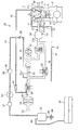
先ず、図1の全体構成図と図2の制御システム図を併せて参照しながら、本実施形態に係るエンジンの蒸発燃料処理装置の全体構成について説明する。
[overall structure]
First, the overall configuration of the evaporated fuel processing apparatus for an engine according to the present embodiment will be described with reference to the overall configuration diagram of FIG. 1 and the control system diagram of FIG.
エンジン1は、例えば直列4気筒型のガソリンエンジンである。ただし、図1において、エンジン1は1気筒のみが図示されており、残りの3気筒の図示は省略されている。なお、本実施形態で説明するエンジン1の構成は一例に過ぎず、本発明において、エンジンの種類や具体的構成は特に限定されるものでない。
The
本実施形態において、エンジン1は、例えば直噴式の燃料供給装置16(図2参照)と、例えば火花点火式の点火装置18(図2参照)とを備えている。
In the present embodiment, the
燃料供給装置16は、エンジン1の燃焼室7を臨むように配設された燃料噴射弁(図示せず)を有し、燃料噴射タイミングにおいて、燃料タンク90から供給されたガソリン燃料を燃料噴射弁から燃焼室7に直接噴射するように構成されている。
The
燃料タンク90は、蒸発燃料通路94を介してキャニスタ92に接続されている。キャニスタ92の内部空間は、外気導入通路96を介して大気に連通されている。燃料タンク90で発生した蒸発燃料は、蒸発燃料通路94を経由して一時的にキャニスタ92に取り込まれた後、大気から外気導入通路96を介してキャニスタ92に導入された空気と共に、後述の吸気系20にパージ(導入)されて、最終的に燃焼室7で燃焼される。なお、外気導入通路96には、蒸発燃料の通過を規制するフィルタ98が設けられており、これにより、キャニスタ92から大気への蒸発燃料の漏出が抑制されている。
The
キャニスタ92から吸気系20へ蒸発燃料をパージするための具体的構成については、後に説明する。
A specific configuration for purging the evaporated fuel from the
点火装置18は、先端電極が燃焼室7を臨むように配設された点火プラグ19を有し、点火タイミングにおいて、点火プラグ19の先端電極から放電火花を発生させるように構成されている。ただし、燃焼室7での着火は、運転状態に応じて、点火プラグ19の点火による着火と、予混合圧縮着火(HCCI)技術による自己着火との間で適宜切り換えられるようにしてもよい。
The
エンジン1は、シリンダブロック3と、該シリンダブロック3の上部に固定されたシリンダヘッド4とを備えている。
The
シリンダブロック3は、気筒毎に、上下方向に延びるシリンダ5を有する。各シリンダ5内には、クランク軸(図示せず)に連結されたピストン6が往復動可能に嵌挿されており、該ピストン6の上方に燃焼室7が形成されている。ピストン6の下方には、クランク軸を収容するクランクケース8が形成されている。
The cylinder block 3 has a cylinder 5 extending in the vertical direction for each cylinder. A piston 6 connected to a crankshaft (not shown) is fitted in each cylinder 5 so as to be able to reciprocate, and a
また、シリンダブロック3には、例えばクランク軸の回転角度を検出することで、エンジン1の回転数を検出するエンジン回転数センサ83(図2参照)と、ウォータジャケット(図示せず)内を流れるエンジン冷却水の温度を検出するエンジン水温センサ84(図2参照)とが配設されている。
Further, the cylinder block 3 flows through an engine speed sensor 83 (see FIG. 2) for detecting the speed of the
シリンダヘッド4には、燃焼室7に連通可能な吸気ポート11と排気ポート12とが、燃焼室7毎に例えば2つずつ形成されている。吸気ポート11のポート開口部には吸気弁13が、排気ポート12のポート開口部には排気弁14がそれぞれ設けられている。吸気弁13及び排気弁14は、例えば電磁VVT(電磁式の可変バルブタイミング機構)によって所定タイミングで独立に開閉動作が行われるようになっている。
In the cylinder head 4, for example, two intake ports 11 and two
各吸気ポート11には吸気系20の吸気通路21が接続され、各排気ポート12には排気系の排気通路60が接続されている。なお、吸気通路21と排気通路60とはEGR通路(図示せず)を介して接続されてもよく、この場合、EGR通路を介して排気通路60の排気ガスの一部を吸気通路21に還流可能となる。
An
エンジン1の吸気系20は、吸気通路21、バイパス通路36、換気通路40及びパージ通路50を備えている。
The
吸気通路21には、その上流側から順に、大気に開放された入口22、入口22から吸入された空気をろ過するエアクリーナ24、吸気通路21を絞るスロットル弁26、吸入空気を圧縮して過給圧を生成する過給機28、過給機28により圧縮された空気を冷却するインタクーラ32、吸入空気を吸気ポート11への供給前に一時的に溜めるサージタンク34が配設されている。
In order from the upstream side to the
吸気通路21におけるエアクリーナ24とスロットル弁26との間の部分には、吸気流量を検出するエアフローセンサ85が設けられている。エアフローセンサ85は例えばホットワイヤ式であり、該エアフローセンサ85には吸気温センサ86(図2参照)が内蔵されている。
An
吸気通路21における過給機28よりも上流側に位置する上流側通路部21a、より具体的には、上流側通路部21aにおけるスロットル弁26と過給機28との間の部分には、当該通路部分の負圧を検出する負圧センサ87が設けられている。
An
吸気通路21における過給機28よりも下流側に位置する下流側通路部21b、より具体的には、下流側通路部21bに位置するサージタンク34には、過給圧を検出する過給圧センサ88が設けられている。
A supercharging pressure for detecting a supercharging pressure is applied to a
吸気通路21の最下流部は、サージタンク34と共にインテークマニホールドを構成する複数の延長通路部21cに分岐されている。延長通路部21cは吸気ポート11毎に設けられており、各吸気ポート11は、延長通路部21cを介してサージタンク34に接続されている。
The most downstream portion of the
過給機28は、例えばベルトを介してエンジン1のクランク軸に駆動連結された機械式のスーパーチャージャである。過給機28の圧縮方式は例えばリショルム式とされるが、特にこれに限定されるものでない。過給機28は、電磁クラッチ30を介してクランク軸に接続されており、電磁クラッチ30が締結ないしスリップ制御されたときにエンジン1の動力が伝達されることで作動し、電磁クラッチ30が解放されることでクランク軸との接続が解除されると作動が停止される。
The
バイパス通路36は、過給機28をバイパスするように吸気通路21に接続されている。つまり、バイパス通路36の一端は、吸気通路21の上流側通路部21aに接続されており、バイパス通路36の他端は、吸気通路21の下流側通路部21bに接続されている。
The
吸気通路21の上流側通路部21aにおいて、バイパス通路36との接続部は、スロットル弁26と過給機28との間に配置され、且つ、負圧センサ87よりも上流側に配置されている。吸気通路21の下流側通路部21bにおいて、バイパス通路36との接続部は、インタクーラ32とサージタンク34との間に配置されている。
In the
バイパス通路36には、該バイパス通路36を開閉する例えばバタフライ式のバイパス制御弁38が設けられている。バイパス制御弁38は、過給機28の作動時に閉じられることでバイパス通路36を遮断して、過給機28による空気の圧縮を促進させる。また、バイパス制御弁38は、過給機28の作動停止時に開放されることで、過給機28を迂回した自然吸気を実現させる。
The
換気通路40は、エンジン1のクランクケース8の換気に用いられる通路であり、第1換気通路としてのブローバイ通路41と、第2換気通路としての空気導入通路42とで構成されている。
The
ブローバイ通路41の一端は、例えばシリンダヘッド4を介してクランクケース8に接続されており、ブローバイ通路41の他端は、吸気通路21の上流側通路部21aに接続されている。上流側通路部21aにおいて、ブローバイ通路41との接続部は、スロットル弁26と過給機28との間、且つ、負圧センサ87よりも上流側に配置されている。
One end of the blow-
ブローバイ通路41には、PCV(Positive Crankcase Ventiration)バルブ44が設けられている。PCVバルブ44は、クランクケース8側から吸気通路21側に向かう方向のみの空気の通過を許容する逆止弁である。PCVバルブ44は、クランクケース8の圧力に比べて吸気通路21の上流側通路部21aの圧力が低いときに開かれるように構成されている。PCVバルブ44が開かれた状態において、燃焼室7からクランクケース8に漏れ出たブローバイガスは、ブローバイ通路41を経由して上流側通路部21aに吸い出される。
A PCV (Positive Crankcase Ventiration) valve 44 is provided in the blow-
PCVバルブ44は、吸気通路21の上流側通路部21aの負圧に応じて開度が変化するように構成されており、これにより、クランクケース8から上流側通路部21aに吸い出されるブローバイガスの流量が、上流側通路部21aの負圧に応じて適量に調整されるようになっている。
The PCV valve 44 is configured so that the opening degree thereof changes in accordance with the negative pressure of the
換気通路40の空気導入通路42の一端は、吸気通路21の上流側通路部21aに接続されており、空気導入通路42の他端は、シリンダヘッド4を介してクランクケース8に接続されている。吸気通路21の上流側通路部21aにおいて、空気導入通路42との接続部は、エアクリーナ24とスロットル弁26との間に配置されている。空気導入通路42には、吸気通路21側からクランクケース8側へ向かう方向のみの空気の通過を許容するワンウェイバルブ46が設けられている。
One end of the
クランクケース8からブローバイ通路41を経由して吸気通路21にブローバイガスが吸い出されるとき、クランクケース8には、大気から吸気通路21に導入されてエアクリーナ24でろ過された空気が空気導入通路42を経由して導入され、これにより、クランクケース8が換気される。
When blow-by gas is sucked into the
パージ通路50の一端は、吸気通路21の上流側通路部21aに接続されており、パージ通路50の他端は、キャニスタ92に接続されている。吸気通路21の上流側通路部21aにおいて、パージ通路50との接続部は、スロットル弁26と過給機28との間、且つ、負圧センサ87よりも上流側に配置されている。
One end of the
パージ通路50には、該パージ通路50を開閉するパージ弁52が設けられている。パージ弁52は、例えば電磁弁で構成されており、パージ弁52の開閉及び開度を電気的に制御可能となっている。
The
パージ弁52が開いた状態において、吸気通路21の上流側通路部21a側に負圧が生じると、キャニスタ92に捕集された蒸発燃料は、大気から外気導入通路96を介してキャニスタ92に導入された空気と共に、パージ通路50を経由して吸気通路21の上流側通路部21aにパージされ、さらに、吸気通路21を経由ないしバイパス通路36と吸気通路21の両方を経由して燃焼室7に供給されて、燃料供給装置16によって供給された燃料と共に燃焼室7で燃焼される。
If a negative pressure is generated on the
また、パージ通路50には、パージ弁52よりも上流側(キャニスタ92側)に、パージ通路50内の圧力を上昇させる加圧手段としてのパージアシスタ54が設けられている。パージアシスタ54は、例えば電動式の遠心ポンプで構成されている。パージ通路50において、パージアシスタ54の上流側及び下流側にはそれぞれチャンバ56,58が設けられている。下流側のチャンバ58には、パージアシスタ54の吐出圧を検出する吐出圧センサ89が設けられている。
The
パージアシスタ54を作動させることにより、パージ通路50内の圧力が高められると、吸気通路21の上流側通路部21a側に負圧が生じていない状態でも、パージ通路50から吸気通路21への蒸発燃料のパージが可能になる。
When the pressure in the
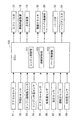
[制御システム]
図2に示すように、エンジン1の動作に関連する各種制御は、制御装置としてのECU(Electronic Control Unit)100によって行われる。ECU100は、例えばマイクロプロセッサを主要部として構成されている。
[Control system]
As shown in FIG. 2, various controls related to the operation of the
ECU100は、アクセルペダル(図示せず)の操作量及び操作速度を検出するアクセルセンサ81、排気通路60(図1参照)に設けられた空燃比センサ82、並びに、上述したエンジン回転数センサ83、エンジン水温センサ84、エアフローセンサ85、吸気温センサ86、負圧センサ87、過給圧センサ88及び吐出圧センサ89に電気的に接続されており、これらのセンサ81〜89の出力信号が入力されるようになっている。
The
また、ECU100は、上述したスロットル弁26、燃料供給装置16、点火装置18、電磁クラッチ30、バイパス制御弁38、パージ弁52及びパージアシスタ54など、エンジン1の動作に関連する各種機器に電気的に接続されており、上述した各種センサ81〜89から受信した信号に基づく制御信号を各種機器に送信することで、エンジン1の種々の動作を制御するように構成されている。
Further, the
ECU100は、エンジン1の基本的な動作を制御するエンジン制御部101、過給機28に関連する動作を制御する過給制御部102、及び、蒸発燃料のパージに関連する動作を制御するパージ制御部103を有する。
The
エンジン制御部101は、アクセルセンサ81、空燃比センサ82、エンジン回転数センサ83、エンジン水温センサ84、エアフローセンサ85、吸気温センサ86等からの入力信号に基づいて、スロットル弁26、燃料供給装置16及び点火装置18の各種動作を制御する。例えば、エンジン制御部101による空燃比制御は、エンジン水温センサ84により検出された水温が所定温度であるときに、空燃比センサ82の出力値とエアフローセンサ85の出力値等に基づいて燃料供給装置16による燃料噴射量が調整されることで行われる。
The
過給制御部102は、エンジン回転数センサ83、エアフローセンサ85等からの入力信号に基づいて、主として、電磁クラッチ30のオン・オフ、並びに、バイパス制御弁38の開閉ないし開度を制御する。
The supercharging
過給制御部102による制御では、エンジン回転数センサ83の出力値とエアフローセンサ85の出力値等によって得られる運転状態が、所定の過給領域に属するときは、バイパス制御弁38が閉状態とされると共に、電磁クラッチ30がオン(締結)されることで、過給機28が作動される。これにより、バイパス通路36が遮断された状態で、過給機28によって効率的に空気を圧縮できる。
In the control by the supercharging
このとき、バイパス制御弁38は、必ずしも全閉状態でなくてもよく、過給圧の過剰な上昇を抑制するためにバイパス制御弁38が若干開かれるようにしてもよい。この場合、過給制御部102は、過給圧センサ88の出力値に基づいて、所望の過給圧が得られるようにバイパス制御弁38の開度を制御するようにしてもよい。
At this time, the
なお、過給領域は、過給を必要とする領域として予め設定された第1運転領域である。具体的には、例えば、エンジン負荷及びエンジン回転数が所定値以上である高負荷・高回転状態の運転領域が過給領域として設定される。また、過給領域以外の第2運転領域は、過給を必要としない非過給領域として設定されている。 The supercharging area is a first operation area that is set in advance as an area that requires supercharging. Specifically, for example, an operation region in a high load / high rotation state in which the engine load and the engine speed are equal to or higher than predetermined values is set as the supercharging region. Further, the second operation region other than the supercharging region is set as a non-supercharging region that does not require supercharging.
エアフローセンサ85の出力値とエンジン回転数センサ83の出力値等によって得られる運転状態が非過給領域に属するとき、過給制御部102による制御では、バイパス制御弁38が開状態(例えば全開状態)とされると共に、電磁クラッチ30がオフ(解放)されることで、過給機28の作動が停止される。これにより、過給機28を迂回した自然吸気が実現される。
When the operating state obtained by the output value of the
パージ制御部103は、主として、パージ弁52の開閉、及び、パージアシスタ54のオン・オフ及び回転数を制御する。
The
パージ制御部103は、所定のパージ条件が成立しているとき、パージ弁52を開状態に制御し、これにより、パージ通路50から吸気通路21への蒸発燃料のパージが可能になる。パージ条件は、例えば、エンジン制御部101によって空燃比制御を適正に行い得る状態であること、より具体的には、例えば、エンジン回転数センサ83によって検出される水温が所定値以上であることである。
The
また、パージ制御部103は、パージ弁52を開いた状態において、必要に応じてパージアシスタ54を作動させる。具体的には、例えば、負圧センサ87の出力値に基づいて吸気通路21の上流側通路部21aに負圧が生じていないときなどに、パージアシスタ54が作動される。
In addition, the
パージ制御部103は、蒸発燃料のパージを実行するとき、運転状態に応じたパージ量になるように、パージ弁52の開度及び/又はパージアシスタ54の回転数が適宜制御される。より具体的に、パージ弁52の開度及び/又はパージアシスタ54の回転数は、エンジン回転数及びエンジン負荷等に基づいて算出されるパージ可能量、燃料タンクの温度等に基づいて算出される蒸発燃料発生量、並びに、負圧センサ87の出力値等に基づいて算出されるパージ容易性等に基づいて適宜制御される。
When purging the evaporated fuel, the
パージ通路50を流れる空気における蒸発燃料の濃度は、吐出圧センサ89の出力値に基づいて算出され得る。この濃度の算出には、ECU100のメモリに予め記憶されたマップが用いられる。
The concentration of the evaporated fuel in the air flowing through the
例えば図3に示すように、該マップは、パージアシスタ54の回転数、流入気体密度及び吐出圧の関係を規定する情報である。図3のマップに示すパージアシスタ54の回転数、流入気体密度及び吐出圧の関係は、回転数が一定であれば吐出圧が高いほど流入気体密度が大きな値となり、吐出圧が一定であれば回転数が低いほど流入気体密度が大きな値となるような関係となっている。
For example, as shown in FIG. 3, the map is information that defines the relationship among the rotational speed of the
したがって、パージ制御部103では、図3に示すマップと、パージ制御部103によるパージアシスタ54の回転数の指令値と、吐出圧センサ89によって検出されるパージアシスタ54の吐出圧とに基づいて、キャニスタ92側からパージアシスタ54に流入される空気の密度が算出され、これにより、該密度に対応する蒸発燃料の濃度が得られる。このようにして算出された蒸発燃料の濃度の値は、エンジン制御部101による空燃比制御に利用される。
Therefore, the
[パージ制御部の制御例]
以下、図4のフローチャートと図5のタイムチャートを併せて参照しながら、パージ制御部103による制御動作の一例について説明する。
[Control example of purge control unit]
Hereinafter, an example of the control operation by the
図4に示す制御動作は、エンジン1が駆動されているとき、パージ制御部103によって繰り返し実行される。
The control operation shown in FIG. 4 is repeatedly executed by the
図4の制御動作において、先ず、ステップS1では、上記のパージ条件が成立しているか否かが判定される。 In the control operation of FIG. 4, first, in step S1, it is determined whether or not the purge condition is satisfied.
ステップS1の判定の結果、パージ条件が成立していない場合、パージ弁52は閉状態に制御されることで(ステップS18)、キャニスタ92からパージ通路50を経由した吸気通路21への蒸発燃料のパージは停止され、パージアシスタ54の作動は停止される(ステップS19)。
If the purge condition is not satisfied as a result of the determination in step S1, the
一方、ステップS1の判定の結果、パージ条件が成立しているときは、ステップS2で、運転状態が過給領域から非過給領域に移行した直後であるか否かが判定される。より具体的に、ステップS2では、過給領域から非過給領域への移行時からの経過時間が予め設定された所定期間以下であるか否かが判定される。 On the other hand, if the purge condition is satisfied as a result of the determination in step S1, it is determined in step S2 whether or not the operating state has just shifted from the supercharging region to the non-supercharging region. More specifically, in step S2, it is determined whether or not the elapsed time from the transition from the supercharging region to the non-supercharging region is equal to or less than a predetermined period set in advance.
ステップS2の判定の結果、過給領域から非過給領域への移行直後でない場合、すなわち、運転状態が過給領域に属する場合、あるいは、運転状態が前記所定期間よりも長く継続して非過給領域に属している場合、パージ弁52が開状態に制御されることで(ステップS20)(図5(b)の符号A参照)、蒸発燃料のパージが実行される。このとき、パージアシスタ54は、回転数N1で駆動される(ステップS17)(図5(c)の符号B参照)。
As a result of the determination in step S2, if it is not immediately after the transition from the supercharging region to the non-supercharging region, that is, if the operating state belongs to the supercharging region, or if the operating state continues longer than the predetermined period, When belonging to the supply region, purge of the evaporated fuel is executed by controlling the
ここで、パージアシスタ54の回転数N1は、運転状態に関係なく予め決められた一定の値であってもよいし、運転状態に応じて適宜制御される値であってもよい。なお、運転状態に応じて回転数N1が制御される場合、パージアシスタ54を作動させることなく適切なパージを行い得る運転状態であれば、回転数N1はゼロに制御される。
Here, the rotational speed N1 of the
一方、ステップS2の判定の結果、過給領域から非過給領域への移行直後である場合、ステップS3で、非過給領域への移行時から蒸発燃料のパージを開始するまでのカウントダウンを行う第1タイマの時間T1が設定済みであるか否かが判定される。 On the other hand, if the result of determination in step S2 is immediately after the transition from the supercharging region to the non-supercharging region, in step S3, a countdown is performed from the time of transition to the non-supercharging region to the start of purge of evaporated fuel. It is determined whether or not the time T1 of the first timer has been set.
ステップS3の判定の結果、時間T1が設定されていない場合、ステップS4で、過給圧センサ88によって検出された非過給領域への移行時の過給圧が読み込まれると共に、ステップS5において、ステップS4で読み込まれた過給圧に応じて、第1タイマの時間T1が設定される。より具体的に、時間T1は、過給圧が高いほど長い時間に設定される。ここで、過給圧と時間T1の関係は、例えば比例関係とされる。
If the time T1 is not set as a result of the determination in step S3, the supercharging pressure at the time of transition to the non-supercharging region detected by the supercharging
したがって、例えば図5(d)の符号Cに示すように、非過給領域への移行時の過給圧が圧力P1であるときの第1タイマの設定時間T1が時間t1である場合、図5(d)の符号Dに示すように、非過給領域への移行時の過給圧が圧力P1よりも高い圧力P2であるときの第1タイマの時間T1は、時間t1よりも長い時間t2に設定される。 Therefore, for example, as shown by reference C in FIG. 5D, when the set time T1 of the first timer when the supercharging pressure at the time of transition to the non-supercharging region is the pressure P1, the time t1 As indicated by reference numeral D in 5 (d), the time T1 of the first timer when the supercharging pressure at the time of transition to the non-supercharging region is a pressure P2 higher than the pressure P1 is longer than the time t1. Set to t2.
続くステップS6では、後述のように第1タイマのカウントダウン終了に伴ってパージが開始されるとき(後述のステップS11参照)のパージアシスタ54の回転数N2(後述のステップS12参照)が、ステップS4で読み込まれた過給圧に応じて設定される。回転数N2は、上記の回転数N1よりも高い値であり、非過給領域への移行時の過給圧が高いほど回転数N2は高い値に設定される。ここで、過給圧と回転数N2の関係は、例えば比例関係とされる。
In the following step S6, the rotation speed N2 (see step S12 described later) of the
ステップS5,S6の時間T1及び回転数N2の設定が完了すると、あるいは、ステップS3において時間T1が設定済みであると判定されたときは、該時間T1がカウントダウンされる(ステップS7)。 When the setting of the time T1 and the rotation speed N2 in steps S5 and S6 is completed, or when it is determined in step S3 that the time T1 has been set, the time T1 is counted down (step S7).
続くステップS8では、第1タイマのカウントダウンが開始されたときからの経過時間が時間T1を経過したか否か、すなわち、第1タイマの残り時間T1がゼロよりも大きいか否かが判定される。 In the following step S8, it is determined whether or not the elapsed time from the start of the countdown of the first timer has passed the time T1, that is, whether or not the remaining time T1 of the first timer is greater than zero. .
ステップS8の判定に基づき、時間T1が経過するまでは、パージ弁52が閉状態に制御されることで(ステップS9)(図5(b)の符号E参照)、パージの実行が停止され、パージアシスタ54の作動は停止される(ステップS10)(図5(c)の符号F参照)。
Based on the determination in step S8, until the time T1 elapses, the
これにより、過給の停止に伴って、自然吸気を行うためにバイパス通路36が開放されるとき、下流側通路部21bにおける比較的高圧の空気がバイパス通路36を通って比較的低圧の上流側通路部21aへ逆流しても、パージ通路50では、閉状態のパージ弁52によって空気の逆流を遮断できる。
Thereby, when the
バイパス通路36での逆流現象が解消されるのに要する時間は、非過給領域への移行時の過給圧が高いほど長くなる傾向があるが、上記のステップS5の時間T1の設定により、非過給領域への移行時の過給圧が高いほど長い時間、パージ弁52が閉じられることから(図5(b)の符号E参照)、バイパス通路36を逆流した空気がパージ通路50に入り込むことを確実に抑制できる。
The time required to eliminate the backflow phenomenon in the
したがって、過給領域から非過給領域へ移行されたときに、パージ通路50での空気の逆流が効果的に抑制されるため、パージ通路50を逆流した空気がキャニスタ92及び外気導入通路96を経由して蒸発燃料と共に大気に放出されることを抑制できる。
Therefore, when the transition is made from the supercharging region to the non-supercharging region, the backflow of air in the
また、吸気系20において特にバイパス通路36及びその周辺部に存在するブローバイガスが、バイパス通路36を逆流する空気に引き連れられてパージ通路50に入り込むことを抑制できるため、パージ弁52等にブローバイガスが付着することを抑制でき、これにより、パージ通路50の詰まりを抑制できる。
Further, in the
その後、ステップS8の判定に基づき、時間T1が経過すると、パージ弁52が開放されることで(ステップS11)(図5(b)の符号G参照)、蒸発燃料のパージが開始され、パージアシスタ54は、ステップS6で設定された回転数N2で駆動される(ステップS12)(図5(c)の符号H参照)。
Thereafter, when the time T1 elapses based on the determination in step S8, the
非過給領域へ移行された後、時間T1が経過するまでの間、パージ通路50における閉状態のパージ弁52よりも下流側部分には、バイパス通路36を逆流する空気と共にブローバイガスが入り込む可能性がある。
After the transition to the non-supercharging region, until the time T1 elapses, blow-by gas can enter the downstream portion of the
これに対して、時間T1が経過したとき、ステップS12において駆動されるパージアシスタ54の吐出圧を利用して、パージ通路50に入り込んだブローバイガスを吸気通路21に追い出すことができる。このとき、パージアシスタ54の回転数N2は、通常時の回転数N1よりも高いことから、パージアシスタ54の高い吐出圧を利用して、効果的にブローバイガスを追い出すことができる。
On the other hand, when the time T1 has elapsed, the blow-by gas that has entered the
また、非過給領域へ移行された後、時間T1が経過するまでの間にパージ通路50に入り込むブローバイガスの量は、非過給領域への移行時の過給圧が高いほど多くなる傾向がある。これに対して、ステップS12で駆動されるパージアシスタ54の回転数N2は、上述のステップS6において、非過給領域への移行時の過給圧が高いほど高い値に設定される。
The amount of blow-by gas that enters the
そのため、より多くのブローバイガスがパージ通路50に溜まっている場合には、例えば図5(c)の符号Iに示すように、パージアシスタ54は、より高い回転数N2で駆動される。このように、パージ通路50に溜まったブローバイガスの量に応じた回転数N2でパージアシスタ54が駆動されることで、パージ通路50から吸気通路21へブローバイガスを確実に追い出すことができる。
Therefore, when a larger amount of blow-by gas is accumulated in the
また、このようにしてパージアシスタ54の吐出圧が通常時よりも上昇されている間、蒸発燃料のパージ量が増大される。そのため、時間T1が経過するまでの間にパージを休止していたことによるパージ量の低減分を相殺することができる。
Further, while the discharge pressure of the
続くステップS13では、回転数N2でのパージアシスタ54の駆動を開始したときから通常時の回転数N2に戻すまでのカウントダウンを行う第2タイマの時間T2が設定済みであるか否かが判定される。
In the subsequent step S13, it is determined whether or not the time T2 of the second timer for performing the countdown from the start of driving the
ステップS13の判定の結果、時間T2が設定されていない場合、ステップS14で、第2タイマの時間T2が設定される。時間T2は、例えば、予め決められた一定の値に設定される。 When the time T2 is not set as a result of the determination in step S13, the time T2 of the second timer is set in step S14. The time T2 is set to a predetermined constant value, for example.
ただし、ステップS14において、時間T2は、ステップS6における回転数N2の設定と同様、ステップS4で読み込まれた非過給領域への移行時の過給圧に応じて、該過給圧が高いほど長い時間に設定されてもよい。また、回転数N2と時間T2のうちいずれか一方を予め決められた一定の値に設定し、他方を、非過給領域への移行時の過給圧が高いほど大きな値に設定するようにしてもよい。 However, in step S14, the time T2 is higher as the supercharging pressure is higher in accordance with the supercharging pressure at the time of transition to the non-supercharging region read in step S4, as in the setting of the rotational speed N2 in step S6. It may be set to a long time. Also, one of the rotational speed N2 and time T2 is set to a predetermined value, and the other is set to a larger value as the supercharging pressure at the time of transition to the non-supercharging region is higher. May be.
ステップS14の時間T2の設定が完了すると、あるいは、ステップS13において時間T2が設定済みであると判定されたときは、該時間T2がカウントダウンされる(ステップS15)。 When the setting of the time T2 in step S14 is completed, or when it is determined in step S13 that the time T2 has been set, the time T2 is counted down (step S15).
続くステップS16では、第2タイマの残り時間T2がゼロよりも大きいか否か、すなわち、回転数N2でのパージアシスタ54の駆動が開始されたときからの経過時間が時間T2未満であるか否かが判定される。
In the subsequent step S16, it is determined whether or not the remaining time T2 of the second timer is greater than zero, that is, whether or not the elapsed time from the start of driving of the
ステップS16の判定に基づき、回転数N2でのパージアシスタ54の駆動が開始されたときから時間T2が経過するまでの間は、パージ弁52が開放された状態で(ステップS11)(図5(b)の符号G参照)、回転数N2でのパージアシスタ54の駆動(ステップS12)(図5(c)の符号H参照)が継続される。
Based on the determination in step S16, the
ステップS16の判定に基づき、回転数N2でのパージアシスタ54の駆動が開始されたときから時間T2が経過すると、パージアシスタ54の回転数N2が通常時の回転数N1に戻される。これ以降は、パージ条件が成立している限り(ステップS1)、パージ弁52を開放した状態でパージアシスタ54を回転数N1で駆動させる通常のパージが行われる。
Based on the determination in step S16, when the time T2 elapses from the start of driving of the
以上、上述の実施形態を挙げて本発明を説明したが、本発明は上述の実施形態に限定されるものではない。 While the present invention has been described with reference to the above-described embodiments, the present invention is not limited to the above-described embodiments.
例えば、上述の本実施形態では、過給機28が、エンジン1の動力によって駆動されるスーパーチャージャである例を説明したが、本発明において、過給機の種類はこれに限られるものでなく、例えば、電動モータの動力によって駆動される電動式のものであってもよい。
For example, in the above-described embodiment, the
以上のように、本発明によれば、スーパーチャージャの作動が停止されるときに、バイパス通路を逆流した空気がパージ通路に入り込むことを抑制することが可能となるから、スーパーチャージャを搭載した自動車の製造産業分野において好適に利用される可能性がある。 As described above, according to the present invention, when the operation of the supercharger is stopped, it is possible to suppress the air that has flowed back through the bypass passage from entering the purge passage. It may be suitably used in the manufacturing industry field.
1 エンジン
3 シリンダブロック
4 シリンダヘッド
8 クランクケース
20 吸気系
21 吸気通路
21a 上流側通路部
21b 下流側通路部
21c 延長通路部
26 スロットル弁
28 過給機
30 電磁クラッチ
36 バイパス通路
38 バイパス制御弁
40 換気通路
41 ブローバイ通路
42 空気導入通路
44 PCVバルブ
50 パージ通路
52 パージ弁
54 パージアシスタ
60 排気通路
88 過給圧センサ
90 燃料タンク
92 キャニスタ
100 ECU
101 エンジン制御部
102 過給制御部(過給制御手段)
103 パージ制御部(パージ制御手段)
DESCRIPTION OF
101
103 Purge control unit (purge control means)
Claims (4)
該吸気通路に設けられた過給機と、
前記吸気通路における前記過給機の上流側と下流側とを繋ぐバイパス通路と、
前記バイパス通路を開閉する制御弁と、
第1運転領域において前記過給機を作動させると共に前記制御弁を閉状態に制御し、第1運転領域とは異なる第2運転領域において前記過給機の作動を停止させると共に前記制御弁を開状態に制御する過給制御手段と、
燃料タンクで発生した蒸発燃料を前記吸気通路に導くために、該吸気通路における前記過給機の上流側に接続されたパージ通路と、
前記パージ通路を開閉するパージ弁と、
前記パージ通路に設けられた加圧手段と、
前記パージ弁の開閉、及び、前記加圧手段の出力を制御するパージ制御手段と、を備えたエンジンの蒸発燃料処理装置であって、
前記パージ制御手段は、前記パージ弁を開き且つ前記加圧手段の出力を第1出力に制御した状態で前記第1運転領域から前記第2運転領域に移行されたとき、前記パージ弁を所定時間閉じて、該所定時間が経過したとき、前記パージ弁を開き、前記加圧手段の出力を前記第1出力よりも大きな第2出力に制御することを特徴とするエンジンの蒸発燃料処理装置。 An intake passage for guiding air to the combustion chamber of the engine;
A supercharger provided in the intake passage;
A bypass passage connecting the upstream side and the downstream side of the supercharger in the intake passage;
A control valve for opening and closing the bypass passage;
The supercharger is operated in the first operation region and the control valve is controlled to be closed, and the operation of the supercharger is stopped and the control valve is opened in a second operation region different from the first operation region. Supercharging control means for controlling the state,
A purge passage connected to the upstream side of the supercharger in the intake passage in order to guide the evaporated fuel generated in the fuel tank to the intake passage;
A purge valve for opening and closing the purge passage;
Pressurizing means provided in the purge passage;
An evaporative fuel processing device for an engine comprising: opening and closing of the purge valve; and purge control means for controlling the output of the pressurizing means;
The purge control means opens the purge valve for a predetermined time when the purge valve is opened and the output of the pressurizing means is controlled to the first output and is shifted from the first operation area to the second operation area. When the engine is closed and the predetermined time has elapsed, the purge valve is opened, and the output of the pressurizing means is controlled to a second output larger than the first output.
前記過給制御手段は、前記断接手段を制御することで前記過給機の作動状態と作動停止状態との間の切り換えを行うことを特徴とする請求項1から請求項3のいずれか1項に記載のエンジンの蒸発燃料処理装置。 The supercharger is a mechanical supercharger connected to the engine via a predetermined connection / disconnection means,
The supercharging control means performs switching between an operating state and an operating stop state of the supercharger by controlling the connecting / disconnecting means. The fuel vapor processing apparatus for an engine according to the item.
Priority Applications (1)
| Application Number | Priority Date | Filing Date | Title |
|---|---|---|---|
| JP2016165729A JP6308263B2 (en) | 2016-08-26 | 2016-08-26 | Engine evaporative fuel processing device |
Applications Claiming Priority (1)
| Application Number | Priority Date | Filing Date | Title |
|---|---|---|---|
| JP2016165729A JP6308263B2 (en) | 2016-08-26 | 2016-08-26 | Engine evaporative fuel processing device |
Publications (2)
| Publication Number | Publication Date |
|---|---|
| JP2018031351A JP2018031351A (en) | 2018-03-01 |
| JP6308263B2 true JP6308263B2 (en) | 2018-04-11 |
Family
ID=61302958
Family Applications (1)
| Application Number | Title | Priority Date | Filing Date |
|---|---|---|---|
| JP2016165729A Expired - Fee Related JP6308263B2 (en) | 2016-08-26 | 2016-08-26 | Engine evaporative fuel processing device |
Country Status (1)
| Country | Link |
|---|---|
| JP (1) | JP6308263B2 (en) |
Families Citing this family (1)
| Publication number | Priority date | Publication date | Assignee | Title |
|---|---|---|---|---|
| JP6414572B2 (en) * | 2016-08-26 | 2018-10-31 | マツダ株式会社 | Engine supercharger |
Family Cites Families (3)
| Publication number | Priority date | Publication date | Assignee | Title |
|---|---|---|---|---|
| JP3338644B2 (en) * | 1997-12-09 | 2002-10-28 | 株式会社ユニシアジェックス | Evaporative fuel treatment system for internal combustion engine |
| JP2007071090A (en) * | 2005-09-06 | 2007-03-22 | Toyota Motor Corp | Control device of internal combustion engine |
| JP2007278094A (en) * | 2006-04-03 | 2007-10-25 | Denso Corp | Purge device |
-
2016
- 2016-08-26 JP JP2016165729A patent/JP6308263B2/en not_active Expired - Fee Related
Also Published As
| Publication number | Publication date |
|---|---|
| JP2018031351A (en) | 2018-03-01 |
Similar Documents
| Publication | Publication Date | Title |
|---|---|---|
| US9109505B2 (en) | Methods and systems for condensation control | |
| JP6414572B2 (en) | Engine supercharger | |
| US8960167B2 (en) | Ventilation control apparatus for internal combustion engine | |
| US8042335B2 (en) | Intake air heating and exhaust cooling | |
| JP5545654B2 (en) | Turbocharged internal combustion engine | |
| US9464586B2 (en) | Exhaust gas recirculation system of engine | |
| JP5649343B2 (en) | Intake throttle control method for internal combustion engine | |
| JP2009174493A (en) | Supercharging device of diesel engine | |
| JP6308264B2 (en) | Engine evaporative fuel processing device | |
| JP2008075589A (en) | Egr gas scavenging device for internal combustion engine | |
| JP2009209784A (en) | Egr control device of engine with supercharger | |
| JP5332674B2 (en) | Exhaust gas recirculation device for internal combustion engine | |
| JP6308263B2 (en) | Engine evaporative fuel processing device | |
| JP2012067609A (en) | Internal combustion engine with turbocharger | |
| WO2018047286A1 (en) | Control method and control device for internal combustion engine | |
| CN110637150B (en) | Air intake and exhaust structure of compressed natural gas engine | |
| JP5688959B2 (en) | Control device for internal combustion engine | |
| JP2010223077A (en) | Internal combustion engine | |
| JP2009526156A (en) | Supercharging system | |
| WO2017110189A1 (en) | Engine control device | |
| JP5769402B2 (en) | Control device for internal combustion engine | |
| JP4206934B2 (en) | Supercharging system for internal combustion engines | |
| JP4232636B2 (en) | Control device for internal combustion engine | |
| JP6613882B2 (en) | Engine control device | |
| JP2014231821A (en) | Controller for internal combustion engine equipped with supercharger |
Legal Events
| Date | Code | Title | Description |
|---|---|---|---|
| TRDD | Decision of grant or rejection written | ||
| A01 | Written decision to grant a patent or to grant a registration (utility model) |
Free format text: JAPANESE INTERMEDIATE CODE: A01 Effective date: 20180213 |
|
| A61 | First payment of annual fees (during grant procedure) |
Free format text: JAPANESE INTERMEDIATE CODE: A61 Effective date: 20180226 |
|
| R150 | Certificate of patent or registration of utility model |
Ref document number: 6308263 Country of ref document: JP Free format text: JAPANESE INTERMEDIATE CODE: R150 |
|
| LAPS | Cancellation because of no payment of annual fees |