JP6307048B2 - Vehicle structure - Google Patents
Vehicle structure Download PDFInfo
- Publication number
- JP6307048B2 JP6307048B2 JP2015122624A JP2015122624A JP6307048B2 JP 6307048 B2 JP6307048 B2 JP 6307048B2 JP 2015122624 A JP2015122624 A JP 2015122624A JP 2015122624 A JP2015122624 A JP 2015122624A JP 6307048 B2 JP6307048 B2 JP 6307048B2
- Authority
- JP
- Japan
- Prior art keywords
- horn
- opening
- vehicle
- air guide
- intercooler
- Prior art date
- Legal status (The legal status is an assumption and is not a legal conclusion. Google has not performed a legal analysis and makes no representation as to the accuracy of the status listed.)
- Active
Links
Images


Classifications
-
- B—PERFORMING OPERATIONS; TRANSPORTING
- B60—VEHICLES IN GENERAL
- B60K—ARRANGEMENT OR MOUNTING OF PROPULSION UNITS OR OF TRANSMISSIONS IN VEHICLES; ARRANGEMENT OR MOUNTING OF PLURAL DIVERSE PRIME-MOVERS IN VEHICLES; AUXILIARY DRIVES FOR VEHICLES; INSTRUMENTATION OR DASHBOARDS FOR VEHICLES; ARRANGEMENTS IN CONNECTION WITH COOLING, AIR INTAKE, GAS EXHAUST OR FUEL SUPPLY OF PROPULSION UNITS IN VEHICLES
- B60K11/00—Arrangement in connection with cooling of propulsion units
- B60K11/08—Air inlets for cooling; Shutters or blinds therefor
-
- G—PHYSICS
- G10—MUSICAL INSTRUMENTS; ACOUSTICS
- G10K—SOUND-PRODUCING DEVICES; METHODS OR DEVICES FOR PROTECTING AGAINST, OR FOR DAMPING, NOISE OR OTHER ACOUSTIC WAVES IN GENERAL; ACOUSTICS NOT OTHERWISE PROVIDED FOR
- G10K9/00—Devices in which sound is produced by vibrating a diaphragm or analogous element, e.g. fog horns, vehicle hooters or buzzers
- G10K9/18—Details, e.g. bulbs, pumps, pistons, switches or casings
- G10K9/22—Mountings; Casings
-
- B—PERFORMING OPERATIONS; TRANSPORTING
- B60—VEHICLES IN GENERAL
- B60C—VEHICLE TYRES; TYRE INFLATION; TYRE CHANGING; CONNECTING VALVES TO INFLATABLE ELASTIC BODIES IN GENERAL; DEVICES OR ARRANGEMENTS RELATED TO TYRES
- B60C5/00—Inflatable pneumatic tyres or inner tubes
-
- B—PERFORMING OPERATIONS; TRANSPORTING
- B60—VEHICLES IN GENERAL
- B60Q—ARRANGEMENT OF SIGNALLING OR LIGHTING DEVICES, THE MOUNTING OR SUPPORTING THEREOF OR CIRCUITS THEREFOR, FOR VEHICLES IN GENERAL
- B60Q5/00—Arrangement or adaptation of acoustic signal devices
Description
本発明は、冷却装置に対して走行風を導風する導風部材を備える車両構造に関する。 The present invention relates to a vehicle structure including an air guide member that guides traveling air to a cooling device.
例えば、特許文献1には、車両のラジエータの車両前側にラジエータグリルを配置し、このラジエータグリルの開口にホーンを配置することが開示されている。 For example, Patent Document 1 discloses disposing a radiator grille on the front side of a vehicle radiator and disposing a horn at the opening of the radiator grille.
特許文献1に開示された構造では、ラジエータの送風範囲内にホーンが配置されているため、ラジエータの冷却能力が低下するおそれがある。このようなラジエータの冷却能力の低下を回避するため、送風範囲外である、例えば、ラジエータの側方にホーンを並設して配置することが考えられる。 In the structure disclosed in Patent Document 1, since the horn is disposed within the blowing range of the radiator, the cooling capacity of the radiator may be reduced. In order to avoid such a decrease in the cooling capacity of the radiator, it is conceivable to arrange a horn in parallel with the radiator, for example, on the side of the radiator.
しかしながら、ラジエータとホーンとを車幅方向で並設した場合、ラジエータへ走行風を導く導風ダクトと、ホーンの拡声部分(例えば、警告音を拡声するメガホーン状の筒体)とをそれぞれ別個に配置する必要がある。このため、走行風を導入する導風ダクトの開口面積が制限され、ラジエータの冷却に必要な十分な開口面積を得るためのレイアウトが困難となる。 However, when the radiator and the horn are arranged side by side in the vehicle width direction, the wind guide duct that guides the traveling wind to the radiator and the horn loudspeaker (for example, a megahorn-like cylinder that louds the warning sound) are separately provided. Need to be placed. For this reason, the opening area of the air guide duct for introducing the traveling wind is limited, and the layout for obtaining a sufficient opening area necessary for cooling the radiator becomes difficult.
本発明は、前記の点に鑑みてなされたものであり、導風部材の導風能力及びホーンの拡声能力をそれぞれ向上させると共に、導風能力と拡声能力とを互いに調和させることが可能な車両構造を提供することを目的とする。 The present invention has been made in view of the above points, and is a vehicle capable of improving the wind guide capability of the wind guide member and the sound output capability of the horn, and harmonizing the wind guide capability and the sound output capability with each other. The purpose is to provide a structure.
前記の目的を達成するために、本発明は、車両への走行風によって冷却される冷却装置と、前記冷却装置へ走行風を導風する導風部材と、前記導風部材の側部に配置されるホーンとを有する車両構造において、前記冷却装置と前記ホーンとは、車幅方向に並設され、
前記導風部材は、前記冷却装置と前記ホーンとの両方にわたる単一の開口を車両前方側に有することを特徴とする。
In order to achieve the above object, the present invention provides a cooling device that is cooled by running wind to a vehicle, a wind guide member that guides running wind to the cooling device, and a side portion of the wind guide member. In the vehicle structure having a horn, the cooling device and the horn are juxtaposed in the vehicle width direction,
The air guide member has a single opening on the vehicle front side that extends over both the cooling device and the horn.
本発明によれば、冷却装置とホーンとを車幅方向で並設し、冷却装置とホーンとの両方にわたる開口を車両前方側に有することで、導風部材の開口によって走行風を冷却装置に好適に導風することができると共に、ホーンによる外部への警告音の伝音を遮ることなく併有することができる。この結果、本発明では、冷却装置とホーンとの両方にわたる開口により、導風部材の導風能力及びホーンの拡声能力をそれぞれ向上させると共に、導風能力と拡声能力とを互いに調和させることができる。 According to the present invention, the cooling device and the horn are juxtaposed in the vehicle width direction, and the opening extending over both the cooling device and the horn is provided on the front side of the vehicle. While being able to guide suitably, it can have together without interrupting the sound transmission of the warning sound to the exterior by a horn. As a result, according to the present invention, the opening extending over both the cooling device and the horn can improve the wind guiding capability of the wind guide member and the horn sounding capability of the horn, respectively, and can harmonize the wind guiding capability and the sound enhancement capability with each other. .
換言すると、本発明では、車幅方向に沿って並設された冷却装置及びホーンがそれぞれ共通して臨む単一の開口を車両前方側に形成することで、この開口から導風される走行風の流量増大による冷却装置の冷却機能の向上と、ホーンの適正な音圧確保機能とを、互いに損なうことなくそれぞれの機能を併有することができる。 In other words, in the present invention, by forming a single opening on the front side of the vehicle in which the cooling device and the horn arranged in parallel along the vehicle width direction face each other, the traveling wind guided from this opening The improvement of the cooling function of the cooling device by the increase in the flow rate of the horn and the function of ensuring the appropriate sound pressure of the horn can be combined with each other without impairing each other.
また、本発明は、前記導風部材が、前記開口に対し前記冷却装置近傍で縮径する出口と、前記開口と前記出口とを繋ぐ斜辺部とを有し、前記ホーンは、前記斜辺部の途中に配置されることを特徴とする。 Further, according to the present invention, the air guide member includes an outlet having a diameter reduced in the vicinity of the cooling device with respect to the opening, and a hypotenuse part connecting the opening and the exit, and the horn is provided on the hypotenuse part. It is arranged in the middle.
本発明によれば、開口に対して出口が縮径する略漏斗状の斜辺部を設け、この斜辺部の途中にホーンを配置することで、斜辺部をホーンの拡声器形状部として機能させることができる。 According to the present invention, by providing a substantially funnel-shaped oblique side portion whose outlet diameter is reduced with respect to the opening and disposing the horn in the middle of the oblique side portion, the oblique side portion functions as a loudspeaker shape portion of the horn. Can do.
さらに、本発明は、前記斜辺部の途中に、前記導風部材の外側に位置する前記ホーンに向かって膨出する膨出部が設けられ、前記膨出部は、車両後方に位置するホーンが臨む膨出部開口と、前記膨出部開口から前記導風部材に連続する裾部とを有することを特徴とする。 Further, according to the present invention, a bulge portion that bulges toward the horn located outside the air guide member is provided in the middle of the oblique side portion, and the bulge portion includes a horn located at the rear of the vehicle. It has a bulging part opening that faces and a skirt part that continues from the bulging part opening to the air guide member.
本発明によれば、斜辺部の途中に、導風部材の外側に位置するホーン側に向かって膨出する膨出部を設けることで、開口から導風された走行風が斜辺部に沿って流通する際、膨出部の裾部が壁面抵抗となって走行風がホーン側に向かって流れづらくなり冷却装置側に向かう流れとすることができる。また、膨出部を膨出部開口と裾部からなる簡素な構造とすることで、膨出部を導風部材と容易に一体成形することができる。 According to the present invention, by providing the bulging portion that bulges toward the horn located outside the air guide member in the middle of the oblique side portion, the traveling wind guided from the opening extends along the oblique side portion. When it circulates, the skirt of the bulging portion becomes a wall resistance, making it difficult for the traveling wind to flow toward the horn and to flow toward the cooling device. In addition, since the bulging portion has a simple structure including the bulging portion opening and the bottom portion, the bulging portion can be easily integrally formed with the air guide member.
さらに、本発明は、前記膨出部開口の開口縁の少なくとも一部が、車幅方向において前記ホーンと重畳するように設けられることを特徴する。 Furthermore, the present invention is characterized in that at least a part of the opening edge of the bulge opening is provided so as to overlap the horn in the vehicle width direction.
本発明によれば、膨出部開口の開口縁の少なくとも一部が、車幅方向においてホーンと重畳することで、例えば、車幅方向における膨出部開口の開口縁とホーンとの間のクリアランスを大きく確保した場合と比較して、冷却装置側への走行風の流れを増大させることができる。 According to the present invention, at least a part of the opening edge of the bulging portion opening overlaps with the horn in the vehicle width direction, for example, the clearance between the opening edge of the bulging portion opening in the vehicle width direction and the horn. Compared with the case where the large is secured, the flow of the traveling wind toward the cooling device can be increased.
さらにまた、本発明は、前記膨出部開口に、該膨出部開口の中心に向かって突出するリップ部が設けられることを特徴とする。 Furthermore, the present invention is characterized in that a lip portion protruding toward the center of the bulge portion opening is provided in the bulge portion opening.
本発明によれば、膨出部開口にリップ部を設けることで、リップ部によって走行風の流れ方向を変更して、冷却装置側への走行風の流れを増大させることができる。 According to the present invention, by providing the lip portion at the bulging portion opening, the flow direction of the traveling wind can be changed by the lip portion, and the flow of the traveling wind toward the cooling device can be increased.
さらにまた、本発明は、前記リップ部が、前記膨出部開口のうち、前記冷却装置と車幅方向において反対側に位置する前記膨出部開口の略半周にわたって設けられることを特徴とする。 Furthermore, the present invention is characterized in that the lip portion is provided over a substantially half circumference of the bulging portion opening located on the opposite side of the bulging portion opening in the vehicle width direction.
本発明によれば、リップ部を、膨出部開口のうち、冷却装置と車幅方向の反対側に位置する膨出部開口の略半周にわたって設けることで、リップ部に当接する走行風の流れを効率良く変更することができると共に、例えば、樹脂成形等によって容易に製造することができる。 According to the present invention, by providing the lip portion over substantially a half circumference of the bulge portion opening located on the opposite side of the cooling device and the vehicle width direction in the bulge portion opening, the flow of the traveling wind contacting the lip portion Can be efficiently changed, and can be easily manufactured by, for example, resin molding.
本発明では、導風部材の導風能力及びホーンの拡声能力をそれぞれ向上させると共に、導風能力と拡声能力とを互いに調和させることが可能な車両構造を得ることができる。 According to the present invention, it is possible to obtain a vehicle structure that can improve the wind guide ability of the wind guide member and the sound enhancement ability of the horn, and can harmonize the wind guide ability and the sound enhancement ability.
次に、本発明の実施形態について、適宜図面を参照しながら詳細に説明する。
なお、各図中において、「前後」は、車両前後方向、「左右」は、運転席から見た左右方向(車幅方向)、「上下」は、鉛直上下方向をそれぞれ示している。
Next, embodiments of the present invention will be described in detail with reference to the drawings as appropriate.
In each figure, “front and rear” indicates the vehicle longitudinal direction, “left and right” indicates the left and right direction (vehicle width direction) viewed from the driver's seat, and “up and down” indicates the vertical vertical direction.
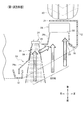
図1に示されるように、車体10は、車体前面に配置されて車幅方向に延在するフロントバンパ12と、フロントバンパ12の下側に設けられるフロントグリル14と、フロントバンパ12に形成されるバンパ開口16(後記する図7参照)に装着され複数の孔部(図示せず)を有するメッシュ18とを備えて構成されている。なお、図1中において、参照数字20は、車体10の左前部側でフロントバンパ12の車両後方に配置された左前輪を示している。また、後記する図7において、参照数字21は、左前輪の一部を被覆するインナフェンダを、それぞれ示している。さらに、図1中において、メッシュ18は、網形状等の詳細な形状を省略し、透過した状態で描出されている。
As shown in FIG. 1, the
図1及び図2に示されるように、メッシュ18の車両後方には、後記するインタクーラ26へ走行風を導風する導風ダクト(導風部材)22と、平面視して導風ダクト22の右側の側部に配置される単一のホーン24(図3参照)と、車両への走行風によって冷却されるインタクーラ(冷却装置)26とが、車両前方から車両後方に向かって概ね順に配置されている。インタクーラ26の車両後方には、左前輪20の一部を被覆するインナフェンダ21が設けられている(後記する図7参照)。
As shown in FIG. 1 and FIG. 2, on the rear side of the
図2に示されるように、導風ダクト22は、例えば、樹脂製材料で一体成形されたダクト本体28を有する。ダクト本体28は、全体として、車幅方向に沿った縦断面が略矩形状に形成されていると共に、車両最後方に位置する出口32(後記する)から車両前方側に向かって徐々に拡径するように形成されている。また、ダクト本体28は、上壁部28aと、上壁部28aに対向する下壁部28bと、車両前方からみて車幅内側に位置する右側壁部28cと、車両前方から見て車幅外側に位置する左側壁部28dとから構成される。ダクト本体28は、車両前方に形成される単一の開口30と、車両後方に形成され開口30に対しインタクーラ26の近傍位置で縮径する出口32とを有する(図3(a)参照)。図3(a)に示されるように、右側壁部28cは、開口30と出口32を繋ぐ斜辺部として機能するものであり、車幅方向内側に偏って張り出す断面湾曲形状に形成されている。これに対して、左側壁部28dは、車両前後方向に沿って断面略直線状に延在するように形成されている。なお、導風ダクト22は、図示しない締結部材を介してバルクヘッド(図示せず)に固定されている。また、メッシュ18は、導風ダクト22の開口30内への塵埃等の進入を阻止すると共に、外観性向上のために設けられている。
As shown in FIG. 2, the
この開口30は、導風ダクト22の車両前方においてインタクーラ26とホーン24との両方にわたって形成されている。換言すると、導風ダクト22の車両前方には、インタクーラ26とホーン24とが共通して臨む単一の開口30が形成されている。右側壁部28cの途中には、図3(a)に示されるように、ホーン24側に向かって車両後方に膨出する膨出部34が形成されている。なお、膨出部34は、後記するように、ホーン24側において拡声器形状部として機能すると共に、導風ダクト22側において、壁面抵抗部として機能するものである。
The
膨出部34は、図3(a)及び図3(b)に示されるように、ホーン24から所定距離だけ離間する円形状開口(膨出部開口)36と、円形状開口36に沿って周回し、且つ、円形状開口36から右側壁部28cに向かって連続する略円弧状の裾部38とを有する。ホーン24に臨む円形状開口36の直径に対し、右側壁部28cに連続する裾部38の部分の直径は、大きく設定されている。このため、円形状開口36及び裾部38によって構成される膨出部34全体は、略漏斗状に形成されている。なお、円形状開口36は、ホーン24の適正な音圧を確保するホーン音圧確保用孔部として機能するものである。
As shown in FIGS. 3A and 3B, the bulging
また、円形状開口36と右側壁部28cとの間における裾部38の幅寸法W(図3(b)参照)は、最も大きい最大部を起点として、一方の周方向及び他方の周方向に向かって徐々に幅狭となり、最大部と円形状開口36の中心を通る反対側で最も幅狭となるように形成されている。膨出部34の円形状開口36の内径は、略円板状からなるホーン24の外径よりも僅かに大きくなるように設定されている。円形状開口36の中心とホーン24の中心とは、一致又は略一致するように設定されている。
Further, the width dimension W (see FIG. 3B) of the
ホーン24は、略円板状の本体部を有し、本体部に形成される前面開口から周囲に警告音を発生させる部品である。ホーン24は、膨出部34に対して車両後方に配置されている。また、図3(a)に示されるように、膨出部34の円形状開口36の円形状開口面37と、ホーン24の前面開口の前面開口面39とは、車両前後方向で相互に対向し、且つ、車幅方向(左右方向)において略平行となるように配置されている。ホーン24とインタクーラ26とは、車幅方向に沿って互いに重畳しないように並設されている。ホーン24の本体部に形成される前面開口面39は、車両前後方向と直交するように配置されている(図3(a)参照)。なお、ホーン24は、図示しない取付部材を介して車体フレームに固定されている。
The
導風ダクト22の出口32には、所定のクリアランスを介して略ボックス状のインタクーラ26が配置されている。フロントバンパ12のバンパ開口16及び導風ダクト22の開口30から導入された走行風は、出口32を介してインタクーラ26に当接するように構成されている。インタクーラ26は、周知のものからなり、走行風が出入する入口部と出口部との間に図示しない複数のフィン及びチューブが配設されている。
A substantially box-shaped
次に、導風ダクト22の膨出部34の円形状開口36とホーン24との間のクリアランスの設定について説明する。図4(a)は、第1実施形態におけるクリアランス設定手法を示す説明図、図4(b)は、比較例におけるクリアランス設定手法を示す説明図である。なお、このクリアランスは、導風ダクト22及びホーン24が互いに異なる部品に固定されているため(導風ダクト22はバルクヘッドに固定、ホーン24は車体フレームに固定)、それらの公差を考慮する必要があると共に、車両の振動による干渉を回避するために必要となる。
Next, the setting of the clearance between the
図4(b)に示されるように、比較例では、膨出部34の円形状開口36とホーン24の前面開口面39との間の車幅方向(左右方向)のクリアランスE2を極力零とする代わりに、車幅方向のクリアランスC2が大きく確保されている。比較例では、導風ダクト22の開口30から導風され右側壁部28cに沿って流通する走行風が、円形状開口36とホーン24との間の車幅方向の大きなクリアランスC2を通過して外部に流出する。このため、比較例では、インタクーラ26側へ向かう走行風の流量が小さくなり、インタクーラ26の冷却に寄与させることが困難である。
As shown in FIG. 4B, in the comparative example, the clearance E2 in the vehicle width direction (left-right direction) between the
これに対して、図4(a)に示されるように、第1実施形態では、比較例に対して、ホーン24が車幅方向(左右方向)において右側壁部28cに寄せて(近接させて)配置されている。これにより、円形状開口36の右端に位置する開口縁36aとホーン24の前面開口の右端は、車幅方向(左右方向)において重畳し(C1=0)、又は、極力零(C1≒0)として配置される代わりに、円形状開口36の開口縁36aとホーン24の前面開口面39との車両前後方向のクリアランスE1を大きく確保することができる。
On the other hand, as shown in FIG. 4A, in the first embodiment, the
第1実施形態では、導風ダクト22の開口30から導風され右側壁部28cに沿って車両後方且つ左方向へ流通する走行風がホーン24の前面に衝突し、走行風の流れ方向がインタクーラ26側とクリアランスE1側へと変更される。走行風の流れ方向はインタクーラ26側とクリアランスE1側へと分かれるが、走行風は元々右側壁部28cに沿って右から左方向へ向けて流れているため、走行風のクリアランスE1側への流れは小さくなる。この結果、本実施形態では、流れ方向がインタクーラ26側へ変更された走行風が発生することにより、比較例と比較して、インタクーラ26側へ向かう走行風の流量が大きくなり、インタクーラ26の冷却に寄与させることができる。
In the first embodiment, the traveling wind that is guided from the
図5(a)は、本発明の第2実施形態に係る車両構造であって、膨出部の円形状開口にリップ部を設けた状態を示す概略構造図、図5(b)は、図5(a)の矢印B方向からみた矢視図である。 FIG. 5A is a schematic diagram showing a vehicle structure according to a second embodiment of the present invention, in which a lip portion is provided in a circular opening of a bulging portion, and FIG. It is an arrow view seen from the arrow B direction of 5 (a).
図5(a)に示す第2実施形態では、膨出部34の円形状開口36に車幅外側方向に向かって僅かに突出するリップ部40を設けている。このリップ部40は、円形状開口36のインタクーラ26と反対側に配置され、円形状開口36の略半周(左右方向における右側略半周)にわたって形成されている。このリップ部40を設けることにより、導風ダクト22の開口30から導風され右側壁部28cに沿って流通する走行風がリップ部40に衝突し、走行風の流れ方向がインタクーラ26側へと変更される。第2実施形態では、流れ方向がインタクーラ26側へ変更された走行風が発生することにより、インタクーラ26側へ向かう走行風の流量が大きくなり、インタクーラ26の冷却に寄与させることができる。第2実施形態では、仮に、膨出部34の円形状開口36とホーン24の前面開口面39との車両前後方向のクリアランスが大きい場合であっても、リップ部40を設けることで、走行風をインタクーラ側へ送ることができる。なお、車両前後方向のクリアランスは、必ずしも大きいことが必要ではなく、例えば、図4(a)に示されるように、車両前後方向のクリアランスE1が小さい場合であっても、さらにリップ部40を設けるようにしてもよい。
In the second embodiment shown in FIG. 5A, a
また、リップ部40を円形状開口36のインタクーラ26と反対側に配置し、且つ、円形状開口36の略半周にわたって設けることで、リップ部40に当接する走行風の流れを効率良く変更することができると共に、例えば、樹脂成形等によって容易に製造することができる。なお、図5(a)に示す第2実施形態では、リップ部40を膨出部34の裾部38と一体的に設けているが、これに限定されるものではなく、リップ部40を裾部38と別体で構成するようにしてもよい。
In addition, by arranging the
図6は、膨出部の壁面抵抗部としての機能の説明に供される部分横断面図である。
膨出部34の裾部38は、導風ダクト22の右側壁部28cから屈曲部41を起点として外方(右側且つ後方)へ屈曲して形成されているため裾部38の内側壁面が抵抗(流路抵抗)となると共に、ホーン24の前面開口の前面開口面39によって膨出部34の膨出部開口36を略閉塞するように、膨出部開口36に対してホーン24を近接配置している。これにより、車両後方のホーン24側に向かって突出して形成される膨出部34の裾部38は、壁面抵抗部として機能する。すなわち、導風ダクト22の開口30から導風された走行風が右側壁部28cに沿って流通する際、膨出部34の裾部38が走行風の流れ方向に対して外側に屈曲して形成されているため、裾部38の壁面抵抗によって屈曲部41から膨出部34の裾部38の内側領域(図6中の網点部分参照)における走行風の流れが遅くなる。一般的に圧力流体は、流れの遅い方から流れの速い方に引っ張られる性質がある。これにより、走行風は、裾部38の壁面抵抗によって走行風の流れが遅い裾部38の内側領域(図6中の網点部分参照)に流れにくくなると共に、インタクーラ26へ向かう速い流れに引っ張られて走行風の強い流れ(太線矢印参照)となる。
FIG. 6 is a partial cross-sectional view for explaining the function of the bulging portion as the wall surface resistance portion.
The
以下の説明では、図1〜図5に示される第1及び第2実施形態の両方を併せて「本実施形態」という。
本実施形態では、導風ダクト22の開口30から導風された走行風の流れを、裾部38の内側領域(図6中の網点部分参照)を除いて乱すことなく、主としてインタクーラ26側へ向かう走行風の強い流れとすることができる。この結果、本実施形態では、インタクーラ26側へ向かう走行風の流量が大きくなり、インタクーラ26の冷却に寄与させることができる。
In the following description, both the first and second embodiments shown in FIGS. 1 to 5 are collectively referred to as “this embodiment”.
In this embodiment, the flow of the traveling wind guided from the
なお、本実施形態では、走行風によって冷却される冷却装置としてインタクーラ26を例示しているが、これに限定されるものではなく、例えば、図示しないラジエータ等の走行風によって冷却される装置であればよい。
In the present embodiment, the
また、本実施形態では、導風部材として導風ダクト22を例示して説明しているが、この場合の「ダクト」とは、導管(筒体)に限定されるものではない。さらに、導風ダクト22は、開口30から出口32に向かって一定の縮径勾配を有するものに限定されるものではなく、例えば、断面段差形状で徐々に内径が小さくなるようなものや、円筒状部とテーパ状部とが組み合われた形状も含まれる。
In the present embodiment, the
さらに、本実施形態では、導風ダクト22、ホーン24、及び、インタクーラ26を車両前方に配置した場合を例示しているが、これに限定されるものではなく、例えば、ミッドシップエンジンのように車両後方に配置してもよい。「車両前方側」とは、導風ダクト22、ホーン24、及び、インタクーラ26を車両後方に配置した場合も含まれる。
Furthermore, in this embodiment, the case where the
本実施形態に係る車両構造が適用された車体10は、基本的に以上のように構成されるものであり、次にその作用効果について説明する。
The
図7は、本実施形態において、走行風の流れ方向及びホーンの音圧領域を示す概略構造断面図、図8は、導風ダクトとホーンとをそれぞれ別個に並設した比較例において、走行風の流れ方向及びホーンの音圧領域を示す概略構造断面図である。なお、図7及び図8において、図1〜図5に示される第1及び第2実施形態と同一の構成要素には、同一の参照符号を付して説明する。また、図7中では、第2実施形態におけるリップ部40の図示を省略している。
FIG. 7 is a schematic sectional view showing the flow direction of the traveling wind and the sound pressure area of the horn in this embodiment. FIG. 8 is a comparative example in which the air guide duct and the horn are separately arranged in parallel. FIG. 2 is a schematic cross-sectional view showing the flow direction and the sound pressure region of the horn. 7 and 8, the same components as those in the first and second embodiments shown in FIGS. 1 to 5 will be described with the same reference numerals. Moreover, in FIG. 7, illustration of the lip | rip
図8に示されるように、導風ダクト22とホーン24とをそれぞれ別個に並設した比較例では、インタクーラ26に対して走行風を導入するための開口(バンパ開口16、開口30)と、ホーン24の音圧確保用の開口との2つの開口がそれぞれ別個に必要となる。このため、車体前部のエンジンルーム等の狭小な空間部において、スペースの有効利用を達成することが困難となる。
As shown in FIG. 8, in the comparative example in which the
また、比較例では、ホーン24とインタクーラ26とをそれぞれ別のスペースに配置しなければならないため、例えば、車幅方向において、ホーン24の配置スペースとインタクーラ26の配置スペースとが加算された広いスペースが必要となる。
In the comparative example, since the
さらに、比較例では、インタクーラ26の冷却能力を向上させるために導風ダクト22の開口面積を大きくした場合、導風ダクト22の開口部分がホーン24の音圧領域(網点領域)に侵入して障害となり、ホーン24の適正な音圧を確保することが困難となる。この結果、比較例では、インタクーラ26の開口面積を大きく設定することができない。
Further, in the comparative example, when the opening area of the
これに対して、本実施形態では、インタクーラ26とホーン24とを車幅方向で並設し、インタクーラ26とホーン24との両方にわたる開口30を車両前方に有することで、導風ダクト22の開口30によって走行風をインタクーラ26に好適に導風することができると共に、ホーン24による外部への警告音の伝音を遮ることなく併有することができる。この結果、本実施形態では、インタクーラ26とホーン24との両方にわたる開口30により、導風ダクト22の導風能力及びホーン24の拡声能力をそれぞれ向上させると共に、導風能力と拡声能力とを互いに調和させることができる。
On the other hand, in this embodiment, the
換言すると、本実施形態では、インタクーラ26及びホーン24がそれぞれ共通して臨む単一の開口30を車両前方に形成することで、この開口30から導風される走行風の流量増大によるインタクーラ26の冷却機能の向上と、ホーン24の適正な音圧確保機能とを、互いに損なうことなくそれぞれの機能を併有することができる。
In other words, in this embodiment, by forming a
また、本実施形態では、開口30に対して出口32が縮径する略漏斗状の右側壁部28cを設け、右側壁部28cの途中にホーンを配置することで、右側壁部28cをホーン24の拡声器形状部として機能させることができる。さらに、右側壁部28cの途中において、右側壁部28cの一部を外方(右側且つ後方)へ膨出させて膨出部34を形成することで、膨出部34の裾部38が壁面抵抗となってホーン24側に向かって流れづらくなりインタクーラ26側に向かう流れとすることができる。さらに、膨出部34を円形状開口36と裾部38とからなる簡素な構造とすることで、膨出部34を導風ダクト22と容易に一体成形することができる。さらにまた、本実施形態では、導風ダクト22に対してホーン24の音圧確保用の孔部(円形状開口36)を形成すると共に、膨出部34自体が拡声器形状部として警報音の拡声機能を有することによって、ホーン24の適正な音圧を確保することができる。
Further, in the present embodiment, a substantially funnel-shaped right
さらに、本実施形態では、車幅方向において、比較例のホーン配置スペース及び音圧領域が不要となるため、導風ダクト22の開口面積をホーン配置スペース及び音圧領域分だけ増大させることができる。この結果、本実施形態では、導風ダクト22の開口面積の増大に伴ってインタクーラ26に導入される走行風の流量を大きくして冷却能力を向上させることができる。
Furthermore, in the present embodiment, the horn arrangement space and the sound pressure region of the comparative example are not required in the vehicle width direction, so that the opening area of the
さらにまた、本実施形態では、ホーン24の音圧領域(図7の網点部分参照)が導風ダクト22内に設定されると共に、ホーン24の伝音を遮断する障害物が何ら配置されていないため、ホーン24の伝音機能を向上させることができる。
Furthermore, in this embodiment, the sound pressure region of the horn 24 (see the halftone dot portion in FIG. 7) is set in the
さらにまた、本実施形態では、導風ダクト22の膨出部34を拡声器形状部として機能させると共に、さらに、導風ダクト22全体をホーン24の警告音を拡声させる拡声器として機能させることができ、ホーン24の拡声機能をより一層向上させることができる。
Furthermore, in the present embodiment, the bulging
さらにまた、本実施形態では、車体正面における適正な音圧確保のためにホーン24を車両正面に向けて配置しているが、インタクーラ26への走行風の流量をより一層増大させるために、適正な音圧が確保されることを条件として、例えば、インタクーラ26側からその反対側に向かって立ち下がるようにホーン24を傾斜して配置するようにしてもよい。
Furthermore, in the present embodiment, the
さらにまた、本実施形態では、比較例と比較してインタクーラ26に導入される走行風の流量を増大させるようにしているが、走行風の流量の増大に伴って風量が増大し、この風量を適正に設定することで、バンパ開口16の開口面積を小さくすることができる。バンパ開口16の開口面積を小さくすることで、車両に対する空力特性が改善し、燃費/最高車速に寄与することができる。
Furthermore, in the present embodiment, the flow rate of the traveling wind introduced into the
さらにまた、本実施形態では、ホーン24の前面に当接する走行風によってインタクーラ26側へ向かう走行風を発生させているが、このホーン24に当接した走行風の流速を遅くさせて走行風の流速をコントロールすることで、右側壁部28cから走行風が剥離することを低減して、インタクーラ26の入口部に導入される走行風を平準化(略均一化)することができる。
Furthermore, in this embodiment, the traveling wind toward the
図9(a)は、第1実施形態における走行風の流れ状態を示す説明図、図9(b)は、導風ダクトの外方にホーンを並設した比較例における走行風の流れ状態を示す説明図である。 FIG. 9A is an explanatory view showing a flow state of the traveling wind in the first embodiment, and FIG. 9B is a flow state of the traveling wind in the comparative example in which a horn is arranged in parallel outside the air guide duct. It is explanatory drawing shown.
図9(b)に示される比較例では、ホーン24に当接する走行風が無いため走行風の流速が速くなり、右側壁部28cから走行風が剥離をして、インタクーラ26の車幅方向の内側領域Dに走行風を導入することが困難となる。これに対して、図9(a)に示される第1実施形態では、ホーン24に当接した走行風の流速が遅くなり、インタクーラ26の車幅方向の内側領域Dに走行風を導入することができる。これにより、第1実施形態では、比較例と比較してインタクーラ26の入口部に導入される走行風の平準化を達成することができる。
In the comparative example shown in FIG. 9B, since there is no traveling wind contacting the
次に、本発明の第3実施形態に係る車体構造について説明する。
図10は、本発明の第3実施形態に係る車両構造が適用された車体の左前部であって、フロントバンパ及びメッシュを取り外した状態を示す斜視図、図11は、図10のXI−XI線に沿った横断面図、図12は、第3実施形態において、走行風の流れ方向及びホーンの音圧・音色領域を示す概略構造断面図である。なお、第3実施形態において、第1及び第2実施形態と同一の構成要素には、同一の参照符号を付してその説明を省略する。
Next, a vehicle body structure according to a third embodiment of the invention will be described.
FIG. 10 is a left front portion of a vehicle body to which the vehicle structure according to the third embodiment of the present invention is applied, and is a perspective view showing a state in which a front bumper and a mesh are removed. FIG. 11 is a cross-sectional view taken along line XI-XI in FIG. FIG. 12 is a schematic structural cross-sectional view showing the flow direction of the traveling wind and the sound pressure / tone color region of the horn in the third embodiment. Note that, in the third embodiment, the same components as those in the first and second embodiments are denoted by the same reference numerals, and description thereof is omitted.
図1〜図3等に示される第1実施形態では、単一のホーン24が設けられているが、第3実施形態では、音圧確保用の第1のホーン24と、音色用の第2のホーン24aとがそれぞれ配置されている点で相違している。第2のホーン24aは、第1のホーン24に対して車幅方向の外側で、且つ、車両後方に配置されている。なお、第2のホーン24aは、第1のホーン24と同様に、図示しない取付部材を介して車体フレームに固定されている。
Although the
導風ダクト22の右側壁部28cには、第2のホーン24aの一部を導風ダクト22内に配置するための切欠部42が形成されている。切欠部42の下面には、断面略半円からなる円弧状切欠部44が形成されている。
A
第3実施形態では、インタクーラ26と、第1のホーン24及び第2のホーン24aとを車幅方向で並設した場合であっても、車両前方においてインタクーラ26と第1のホーン24及び第2のホーン24aとの両方にわたる開口30を有することで、導風ダクト22の導風能力及び第1のホーン24の拡声能力をそれぞれ向上させると共に、導風能力と拡声能力とを互いに調和させることができる。
In the third embodiment, even when the
第3実施形態では、第1のホーン24及び第2のホーン24aからなる2つのホーンを配置した場合であっても、導風ダクト22の開口30を大きくすることで、インタクーラ26の冷却効果を向上させることができる。
In the third embodiment, even when two horns including the
また、第3実施形態では、導風ダクト22の右側壁部28cに切欠部42を形成することで、第2のホーン24aの障害物を無くして、導風ダクト22全体を拡声器構造とすることができる。
Moreover, in 3rd Embodiment, the obstruction of the
なお、その他の作用効果は、第1及び第2実施形態と同一であるため、その詳細な説明を省略する。 Since other operational effects are the same as those of the first and second embodiments, detailed description thereof is omitted.
10、10a 車体
22 導風ダクト(導風部材)
24 ホーン
26 インタクーラ(冷却装置)
28c 右側壁部(斜辺部)
30 開口
32 出口
34 膨出部
36 円形状開口(膨出部開口)
38 裾部
40 リップ部
10,
24
28c Right side wall (slope side)
30
38
Claims (6)
前記冷却装置へ走行風を導風する導風部材と、
前記導風部材の側部に配置されるホーンとを有する車両構造において、
前記冷却装置と前記ホーンとは、車幅方向に並設され、
前記導風部材は、前記冷却装置と前記ホーンとの両方にわたる単一の開口を車両前方側
に有することを特徴とする車両構造。 A cooling device that is cooled by the driving wind to the vehicle;
A wind guide member for guiding running air to the cooling device;
In a vehicle structure having a horn disposed on a side portion of the air guide member,
The cooling device and the horn are juxtaposed in the vehicle width direction,
The vehicle structure according to claim 1, wherein the air guide member has a single opening on the vehicle front side that extends over both the cooling device and the horn.
前記導風部材は、前記開口に対し前記冷却装置近傍で縮径する出口と、前記開口と前記
出口とを繋ぐ斜辺部とを有し、
前記ホーンは、前記斜辺部の途中に配置されることを特徴とする車両構造。 The vehicle structure according to claim 1,
The air guide member has an outlet that is reduced in diameter in the vicinity of the cooling device with respect to the opening, and a hypotenuse that connects the opening and the outlet,
The horn is disposed in the middle of the oblique side portion.
前記斜辺部の途中には、前記導風部材の外側に位置する前記ホーンに向かって膨出する
膨出部が設けられ、
前記膨出部は、車両後方に位置するホーンが臨む膨出部開口と、前記膨出部開口から前
記導風部材に連続する裾部とを有することを特徴とする車両構造。 The vehicle structure according to claim 2, wherein
In the middle of the oblique side portion, a bulging portion that bulges toward the horn located outside the air guide member is provided,
The bulge portion has a bulge portion opening facing a horn located at the rear of the vehicle, and a skirt portion that continues from the bulge portion opening to the air guide member.
前記膨出部開口の開口縁の少なくとも一部は、車幅方向において前記ホーンと重畳する
ように設けられることを特徴する車両構造。 The vehicle structure according to claim 3,
At least a part of the opening edge of the bulge opening is provided so as to overlap the horn in the vehicle width direction.
前記膨出部開口には、該膨出部開口の中心に向かって突出するリップ部が設けられるこ
とを特徴とする車両構造。 In the vehicle structure according to claim 3 or 4,
The bulge portion opening is provided with a lip portion that protrudes toward the center of the bulge portion opening.
前記リップ部は、前記膨出部開口のうち、前記冷却装置と車幅方向において反対側に位
置する前記膨出部開口の略半周にわたって設けられることを特徴とする車両構造。 The vehicle structure according to claim 5, wherein
The vehicle structure according to claim 1, wherein the lip portion is provided over a substantially half circumference of the bulge portion opening located on the opposite side in the vehicle width direction to the cooling device in the bulge portion opening.
Priority Applications (3)
| Application Number | Priority Date | Filing Date | Title |
|---|---|---|---|
| JP2015122624A JP6307048B2 (en) | 2015-06-18 | 2015-06-18 | Vehicle structure |
| CN201610325897.4A CN106256585B (en) | 2015-06-18 | 2016-05-17 | Vehicle structure |
| US15/172,154 US9834087B2 (en) | 2015-06-18 | 2016-06-03 | Vehicle structure |
Applications Claiming Priority (1)
| Application Number | Priority Date | Filing Date | Title |
|---|---|---|---|
| JP2015122624A JP6307048B2 (en) | 2015-06-18 | 2015-06-18 | Vehicle structure |
Publications (3)
| Publication Number | Publication Date |
|---|---|
| JP2017008748A JP2017008748A (en) | 2017-01-12 |
| JP2017008748A5 JP2017008748A5 (en) | 2017-12-14 |
| JP6307048B2 true JP6307048B2 (en) | 2018-04-04 |
Family
ID=57587613
Family Applications (1)
| Application Number | Title | Priority Date | Filing Date |
|---|---|---|---|
| JP2015122624A Active JP6307048B2 (en) | 2015-06-18 | 2015-06-18 | Vehicle structure |
Country Status (3)
| Country | Link |
|---|---|
| US (1) | US9834087B2 (en) |
| JP (1) | JP6307048B2 (en) |
| CN (1) | CN106256585B (en) |
Families Citing this family (11)
| Publication number | Priority date | Publication date | Assignee | Title |
|---|---|---|---|---|
| JP6870473B2 (en) * | 2017-05-23 | 2021-05-12 | スズキ株式会社 | Cooling structure of internal combustion engine for vehicles |
| DE102017129245A1 (en) * | 2017-12-08 | 2019-06-13 | Dr. Ing. H.C. F. Porsche Aktiengesellschaft | Air intake device for a cooling device of an electric vehicle |
| EP3536555B1 (en) * | 2018-03-05 | 2022-07-27 | Volvo Car Corporation | Vehicle front structure comprising a horn |
| DE102018105725A1 (en) * | 2018-03-13 | 2019-09-19 | Dr. Ing. H.C. F. Porsche Aktiengesellschaft | Front part for a motor vehicle |
| US11089372B2 (en) * | 2018-03-28 | 2021-08-10 | Rovi Guides, Inc. | Systems and methods to provide media asset recommendations based on positioning of internet connected objects on an network-connected surface |
| DE102018218520A1 (en) * | 2018-10-30 | 2020-04-30 | Volkswagen Aktiengesellschaft | Arrangement of an air guide element made of foam on a cooler element and cooler element and air guide element made of foam |
| JP6934502B2 (en) * | 2019-10-18 | 2021-09-15 | 本田技研工業株式会社 | Vehicle front structure |
| JP7260492B2 (en) * | 2020-01-30 | 2023-04-18 | トヨタ自動車株式会社 | car |
| JP7339216B2 (en) * | 2020-07-27 | 2023-09-05 | トヨタ自動車株式会社 | vehicle front structure |
| DE102020123969A1 (en) | 2020-09-15 | 2022-03-17 | Bayerische Motoren Werke Aktiengesellschaft | Arrangement for a motor vehicle and motor vehicle comprising such an arrangement |
| US11458891B1 (en) * | 2021-04-05 | 2022-10-04 | Toyota Research Institute, Inc. | Secondary horn system for a vehicle |
Family Cites Families (16)
| Publication number | Priority date | Publication date | Assignee | Title |
|---|---|---|---|---|
| JPS61192958U (en) * | 1985-05-27 | 1986-12-01 | ||
| JPH02110532U (en) * | 1989-02-22 | 1990-09-04 | ||
| DE3927227A1 (en) * | 1989-08-18 | 1991-02-21 | Krantz H Gmbh & Co | AIR OUTLET |
| JP2528539B2 (en) * | 1990-07-17 | 1996-08-28 | 日産自動車株式会社 | Automotive horn mounting structure |
| JP2001260748A (en) * | 2000-03-15 | 2001-09-26 | Denso Corp | Front end panel |
| JP4304806B2 (en) * | 2000-01-28 | 2009-07-29 | 株式会社デンソー | Front end panel |
| JP2004353265A (en) * | 2003-05-28 | 2004-12-16 | Shin Caterpillar Mitsubishi Ltd | Bottom guard of construction machine, engine room structure of construction machine and engine cooling device of construction machine |
| JP4563869B2 (en) * | 2005-05-25 | 2010-10-13 | 本田技研工業株式会社 | Automobile intake structure |
| JP4702014B2 (en) * | 2005-11-30 | 2011-06-15 | マツダ株式会社 | Vehicle cooling device |
| US20070243818A1 (en) * | 2006-03-30 | 2007-10-18 | Calsonickansei North America, Inc. | Air Guide for front end cooling |
| JP2009166803A (en) * | 2008-01-21 | 2009-07-30 | Mazda Motor Corp | Arrangement structure of horn for vehicle |
| JP2010163075A (en) | 2009-01-16 | 2010-07-29 | Toyota Motor Corp | Control method of grille shutter for vehicle |
| DE102010017320B4 (en) * | 2010-06-10 | 2024-01-04 | Dr. Ing. H.C. F. Porsche Aktiengesellschaft | Motor vehicle with sound conducting element |
| US8998293B2 (en) * | 2010-06-22 | 2015-04-07 | Ford Global Technologies, Llc | Airflow control device for an automotive vehicle |
| JP5976512B2 (en) * | 2012-09-27 | 2016-08-23 | ダイハツ工業株式会社 | Vehicle horn protection structure |
| FR3010947B1 (en) * | 2013-09-20 | 2015-09-04 | Renault Sa | COOLING DEVICE FOR A FRONT TECHNICAL FRONT STRUCTURE OF A MOTOR VEHICLE C |
-
2015
- 2015-06-18 JP JP2015122624A patent/JP6307048B2/en active Active
-
2016
- 2016-05-17 CN CN201610325897.4A patent/CN106256585B/en active Active
- 2016-06-03 US US15/172,154 patent/US9834087B2/en active Active
Also Published As
| Publication number | Publication date |
|---|---|
| CN106256585A (en) | 2016-12-28 |
| CN106256585B (en) | 2018-08-07 |
| JP2017008748A (en) | 2017-01-12 |
| US20160368364A1 (en) | 2016-12-22 |
| US9834087B2 (en) | 2017-12-05 |
Similar Documents
| Publication | Publication Date | Title |
|---|---|---|
| JP6307048B2 (en) | Vehicle structure | |
| US8128158B1 (en) | Method and device for attenuating aerodynamically induced noises caused by vehicle grille | |
| US11712996B2 (en) | Sound-producing device for vehicle | |
| JP2017193223A (en) | Attachment structure of peripheral information detection sensor | |
| JP4968096B2 (en) | Intake device for internal combustion engine for vehicle | |
| JP5803185B2 (en) | Rear spoiler | |
| JP4563869B2 (en) | Automobile intake structure | |
| JP2012017036A (en) | Mounting structure of horn for vehicle | |
| JP6699578B2 (en) | Vehicle front structure | |
| JP2006335087A (en) | Ventilation structure of vehicle | |
| JP4985010B2 (en) | Automotive front structure | |
| JP6191550B2 (en) | Aerodynamic structure for vehicles | |
| JP6642548B2 (en) | Lower body structure | |
| JP6919483B2 (en) | Warning structure | |
| JP6851439B2 (en) | Vehicle front structure | |
| JP2020083108A (en) | Front structure of vehicle | |
| JP7347399B2 (en) | Heat shield structure for turbocharger | |
| JP7192515B2 (en) | engine cover | |
| JP2018047779A (en) | Vehicle undercover structure | |
| JP7322677B2 (en) | vehicle undercarriage | |
| JP2016068808A (en) | Deflector of vehicle | |
| JP6182078B2 (en) | Instrument panel structure | |
| JP2011143867A (en) | Grille of vehicle body front part | |
| JP2008162419A (en) | Vehicular ventilation device | |
| JP2020124954A (en) | Vehicle front part structure |
Legal Events
| Date | Code | Title | Description |
|---|---|---|---|
| A521 | Written amendment |
Free format text: JAPANESE INTERMEDIATE CODE: A523 Effective date: 20171102 |
|
| A621 | Written request for application examination |
Free format text: JAPANESE INTERMEDIATE CODE: A621 Effective date: 20171102 |
|
| A871 | Explanation of circumstances concerning accelerated examination |
Free format text: JAPANESE INTERMEDIATE CODE: A871 Effective date: 20171102 |
|
| A621 | Written request for application examination |
Free format text: JAPANESE INTERMEDIATE CODE: A621 Effective date: 20171129 |
|
| A975 | Report on accelerated examination |
Free format text: JAPANESE INTERMEDIATE CODE: A971005 Effective date: 20171204 |
|
| A131 | Notification of reasons for refusal |
Free format text: JAPANESE INTERMEDIATE CODE: A131 Effective date: 20171212 |
|
| A521 | Written amendment |
Free format text: JAPANESE INTERMEDIATE CODE: A523 Effective date: 20180213 |
|
| TRDD | Decision of grant or rejection written | ||
| A01 | Written decision to grant a patent or to grant a registration (utility model) |
Free format text: JAPANESE INTERMEDIATE CODE: A01 Effective date: 20180227 |
|
| A61 | First payment of annual fees (during grant procedure) |
Free format text: JAPANESE INTERMEDIATE CODE: A61 Effective date: 20180309 |
|
| R150 | Certificate of patent or registration of utility model |
Ref document number: 6307048 Country of ref document: JP Free format text: JAPANESE INTERMEDIATE CODE: R150 |