JP6302249B2 - Sulfur-containing nanoporous materials, nanoparticles, methods and applications - Google Patents
Sulfur-containing nanoporous materials, nanoparticles, methods and applications Download PDFInfo
- Publication number
- JP6302249B2 JP6302249B2 JP2013538819A JP2013538819A JP6302249B2 JP 6302249 B2 JP6302249 B2 JP 6302249B2 JP 2013538819 A JP2013538819 A JP 2013538819A JP 2013538819 A JP2013538819 A JP 2013538819A JP 6302249 B2 JP6302249 B2 JP 6302249B2
- Authority
- JP
- Japan
- Prior art keywords
- sulfur
- carbon material
- nanoparticles
- cyclic voltammogram
- carbon
- Prior art date
- Legal status (The legal status is an assumption and is not a legal conclusion. Google has not performed a legal analysis and makes no representation as to the accuracy of the status listed.)
- Expired - Fee Related
Links
Images


Classifications
-
- H—ELECTRICITY
- H01—ELECTRIC ELEMENTS
- H01M—PROCESSES OR MEANS, e.g. BATTERIES, FOR THE DIRECT CONVERSION OF CHEMICAL ENERGY INTO ELECTRICAL ENERGY
- H01M4/00—Electrodes
- H01M4/02—Electrodes composed of, or comprising, active material
- H01M4/36—Selection of substances as active materials, active masses, active liquids
- H01M4/58—Selection of substances as active materials, active masses, active liquids of inorganic compounds other than oxides or hydroxides, e.g. sulfides, selenides, tellurides, halogenides or LiCoFy; of polyanionic structures, e.g. phosphates, silicates or borates
- H01M4/583—Carbonaceous material, e.g. graphite-intercalation compounds or CFx
- H01M4/587—Carbonaceous material, e.g. graphite-intercalation compounds or CFx for inserting or intercalating light metals
-
- H—ELECTRICITY
- H01—ELECTRIC ELEMENTS
- H01M—PROCESSES OR MEANS, e.g. BATTERIES, FOR THE DIRECT CONVERSION OF CHEMICAL ENERGY INTO ELECTRICAL ENERGY
- H01M4/00—Electrodes
- H01M4/02—Electrodes composed of, or comprising, active material
- H01M4/13—Electrodes for accumulators with non-aqueous electrolyte, e.g. for lithium-accumulators; Processes of manufacture thereof
- H01M4/136—Electrodes based on inorganic compounds other than oxides or hydroxides, e.g. sulfides, selenides, tellurides, halogenides or LiCoFy
-
- B—PERFORMING OPERATIONS; TRANSPORTING
- B82—NANOTECHNOLOGY
- B82B—NANOSTRUCTURES FORMED BY MANIPULATION OF INDIVIDUAL ATOMS, MOLECULES, OR LIMITED COLLECTIONS OF ATOMS OR MOLECULES AS DISCRETE UNITS; MANUFACTURE OR TREATMENT THEREOF
- B82B3/00—Manufacture or treatment of nanostructures by manipulation of individual atoms or molecules, or limited collections of atoms or molecules as discrete units
-
- H—ELECTRICITY
- H01—ELECTRIC ELEMENTS
- H01M—PROCESSES OR MEANS, e.g. BATTERIES, FOR THE DIRECT CONVERSION OF CHEMICAL ENERGY INTO ELECTRICAL ENERGY
- H01M10/00—Secondary cells; Manufacture thereof
- H01M10/05—Accumulators with non-aqueous electrolyte
- H01M10/052—Li-accumulators
-
- H—ELECTRICITY
- H01—ELECTRIC ELEMENTS
- H01M—PROCESSES OR MEANS, e.g. BATTERIES, FOR THE DIRECT CONVERSION OF CHEMICAL ENERGY INTO ELECTRICAL ENERGY
- H01M10/00—Secondary cells; Manufacture thereof
- H01M10/05—Accumulators with non-aqueous electrolyte
- H01M10/052—Li-accumulators
- H01M10/0525—Rocking-chair batteries, i.e. batteries with lithium insertion or intercalation in both electrodes; Lithium-ion batteries
-
- H—ELECTRICITY
- H01—ELECTRIC ELEMENTS
- H01M—PROCESSES OR MEANS, e.g. BATTERIES, FOR THE DIRECT CONVERSION OF CHEMICAL ENERGY INTO ELECTRICAL ENERGY
- H01M10/00—Secondary cells; Manufacture thereof
- H01M10/36—Accumulators not provided for in groups H01M10/05-H01M10/34
- H01M10/39—Accumulators not provided for in groups H01M10/05-H01M10/34 working at high temperature
-
- H—ELECTRICITY
- H01—ELECTRIC ELEMENTS
- H01M—PROCESSES OR MEANS, e.g. BATTERIES, FOR THE DIRECT CONVERSION OF CHEMICAL ENERGY INTO ELECTRICAL ENERGY
- H01M4/00—Electrodes
- H01M4/02—Electrodes composed of, or comprising, active material
- H01M4/04—Processes of manufacture in general
- H01M4/0402—Methods of deposition of the material
- H01M4/0416—Methods of deposition of the material involving impregnation with a solution, dispersion, paste or dry powder
-
- H—ELECTRICITY
- H01—ELECTRIC ELEMENTS
- H01M—PROCESSES OR MEANS, e.g. BATTERIES, FOR THE DIRECT CONVERSION OF CHEMICAL ENERGY INTO ELECTRICAL ENERGY
- H01M4/00—Electrodes
- H01M4/02—Electrodes composed of, or comprising, active material
- H01M4/13—Electrodes for accumulators with non-aqueous electrolyte, e.g. for lithium-accumulators; Processes of manufacture thereof
- H01M4/133—Electrodes based on carbonaceous material, e.g. graphite-intercalation compounds or CFx
-
- H—ELECTRICITY
- H01—ELECTRIC ELEMENTS
- H01M—PROCESSES OR MEANS, e.g. BATTERIES, FOR THE DIRECT CONVERSION OF CHEMICAL ENERGY INTO ELECTRICAL ENERGY
- H01M4/00—Electrodes
- H01M4/02—Electrodes composed of, or comprising, active material
- H01M4/13—Electrodes for accumulators with non-aqueous electrolyte, e.g. for lithium-accumulators; Processes of manufacture thereof
- H01M4/137—Electrodes based on electro-active polymers
-
- H—ELECTRICITY
- H01—ELECTRIC ELEMENTS
- H01M—PROCESSES OR MEANS, e.g. BATTERIES, FOR THE DIRECT CONVERSION OF CHEMICAL ENERGY INTO ELECTRICAL ENERGY
- H01M4/00—Electrodes
- H01M4/02—Electrodes composed of, or comprising, active material
- H01M4/13—Electrodes for accumulators with non-aqueous electrolyte, e.g. for lithium-accumulators; Processes of manufacture thereof
- H01M4/139—Processes of manufacture
- H01M4/1397—Processes of manufacture of electrodes based on inorganic compounds other than oxides or hydroxides, e.g. sulfides, selenides, tellurides, halogenides or LiCoFy
-
- H—ELECTRICITY
- H01—ELECTRIC ELEMENTS
- H01M—PROCESSES OR MEANS, e.g. BATTERIES, FOR THE DIRECT CONVERSION OF CHEMICAL ENERGY INTO ELECTRICAL ENERGY
- H01M4/00—Electrodes
- H01M4/02—Electrodes composed of, or comprising, active material
- H01M4/13—Electrodes for accumulators with non-aqueous electrolyte, e.g. for lithium-accumulators; Processes of manufacture thereof
- H01M4/139—Processes of manufacture
- H01M4/1399—Processes of manufacture of electrodes based on electro-active polymers
-
- H—ELECTRICITY
- H01—ELECTRIC ELEMENTS
- H01M—PROCESSES OR MEANS, e.g. BATTERIES, FOR THE DIRECT CONVERSION OF CHEMICAL ENERGY INTO ELECTRICAL ENERGY
- H01M4/00—Electrodes
- H01M4/02—Electrodes composed of, or comprising, active material
- H01M4/36—Selection of substances as active materials, active masses, active liquids
- H01M4/58—Selection of substances as active materials, active masses, active liquids of inorganic compounds other than oxides or hydroxides, e.g. sulfides, selenides, tellurides, halogenides or LiCoFy; of polyanionic structures, e.g. phosphates, silicates or borates
- H01M4/583—Carbonaceous material, e.g. graphite-intercalation compounds or CFx
-
- H—ELECTRICITY
- H01—ELECTRIC ELEMENTS
- H01M—PROCESSES OR MEANS, e.g. BATTERIES, FOR THE DIRECT CONVERSION OF CHEMICAL ENERGY INTO ELECTRICAL ENERGY
- H01M4/00—Electrodes
- H01M4/02—Electrodes composed of, or comprising, active material
- H01M4/64—Carriers or collectors
- H01M4/66—Selection of materials
- H01M4/663—Selection of materials containing carbon or carbonaceous materials as conductive part, e.g. graphite, carbon fibres
-
- H—ELECTRICITY
- H01—ELECTRIC ELEMENTS
- H01M—PROCESSES OR MEANS, e.g. BATTERIES, FOR THE DIRECT CONVERSION OF CHEMICAL ENERGY INTO ELECTRICAL ENERGY
- H01M4/00—Electrodes
- H01M4/02—Electrodes composed of, or comprising, active material
- H01M4/64—Carriers or collectors
- H01M4/66—Selection of materials
- H01M4/664—Ceramic materials
-
- H—ELECTRICITY
- H01—ELECTRIC ELEMENTS
- H01M—PROCESSES OR MEANS, e.g. BATTERIES, FOR THE DIRECT CONVERSION OF CHEMICAL ENERGY INTO ELECTRICAL ENERGY
- H01M10/00—Secondary cells; Manufacture thereof
- H01M10/36—Accumulators not provided for in groups H01M10/05-H01M10/34
- H01M10/39—Accumulators not provided for in groups H01M10/05-H01M10/34 working at high temperature
- H01M10/3909—Sodium-sulfur cells
-
- Y—GENERAL TAGGING OF NEW TECHNOLOGICAL DEVELOPMENTS; GENERAL TAGGING OF CROSS-SECTIONAL TECHNOLOGIES SPANNING OVER SEVERAL SECTIONS OF THE IPC; TECHNICAL SUBJECTS COVERED BY FORMER USPC CROSS-REFERENCE ART COLLECTIONS [XRACs] AND DIGESTS
- Y02—TECHNOLOGIES OR APPLICATIONS FOR MITIGATION OR ADAPTATION AGAINST CLIMATE CHANGE
- Y02E—REDUCTION OF GREENHOUSE GAS [GHG] EMISSIONS, RELATED TO ENERGY GENERATION, TRANSMISSION OR DISTRIBUTION
- Y02E60/00—Enabling technologies; Technologies with a potential or indirect contribution to GHG emissions mitigation
- Y02E60/10—Energy storage using batteries
Landscapes
- Chemical & Material Sciences (AREA)
- Engineering & Computer Science (AREA)
- General Chemical & Material Sciences (AREA)
- Chemical Kinetics & Catalysis (AREA)
- Electrochemistry (AREA)
- Materials Engineering (AREA)
- Manufacturing & Machinery (AREA)
- Inorganic Chemistry (AREA)
- Crystallography & Structural Chemistry (AREA)
- Nanotechnology (AREA)
- Ceramic Engineering (AREA)
- Dispersion Chemistry (AREA)
- Battery Electrode And Active Subsutance (AREA)
- Secondary Cells (AREA)
- Carbon And Carbon Compounds (AREA)
Description
(関連出願の相互参照)
本出願は、2010年11月9日に提出され、発明の名称が、リチウムバッテリーのためのナノ複合材料、装置、方法、およびアプリケーションとされた、米国仮特許出願第61/411,645号に関連し、当該仮特許出願に基づく優先権を主張する。当該仮特許出願の内容は、本明細書に引用して援用する。
(Cross-reference of related applications)
This application is filed on Nov. 9, 2010 and the title of the invention is in US Provisional Patent Application No. 61 / 411,645, which is a nanocomposite material, apparatus, method, and application for a lithium battery. Relevant and claim priority based on the provisional patent application. The contents of the provisional patent application are incorporated herein by reference.
(発明の分野)
本実施態様は、概して、硫黄含有ナノポーラス材料およびナノ粒子に関する。より詳細には、本実施態様は、硫黄含有ナノポーラス材料、ナノ粒子、方法およびアプリケーションに関する。
(Field of Invention)
This embodiment generally relates to sulfur-containing nanoporous materials and nanoparticles. More particularly, this embodiment relates to sulfur-containing nanoporous materials, nanoparticles, methods and applications.
従来技術の説明
二次リチウムバッテリーのためのカソード材料の中で、元素である硫黄は、リチウムを基準として非常に高い理論キャパシティー1672mAhg−1を有する。これは、多くの商業的に使用されている遷移金属リン酸塩および遷移金属酸化物の理論キャパシティーより極めて大きい。さらに、元素の硫黄により、二次リチウムバッテリーのためのカソード材料として他のいくつかの利点(特にコストが安いとか広く普及しているという利点を含む)が得られる。それゆえ、硫黄は、二次リチウムバッテリーのためのカソード材料として幅広く研究され、電気自動車およびハイブリッド電気自動車において使用されうる二次リチウムバッテリーのためのカソード材料の有望な候補と考えられている。
Description of the Prior Art Among the cathode materials for secondary lithium batteries, the elemental sulfur has a very high theoretical capacity of 1672 mAhg −1 based on lithium. This is much greater than the theoretical capacity of many commercially used transition metal phosphates and transition metal oxides. In addition, elemental sulfur provides several other advantages as cathode materials for secondary lithium batteries, including particularly low cost and widespread use. Therefore, sulfur has been extensively studied as a cathode material for secondary lithium batteries and is considered a promising candidate for cathode materials for secondary lithium batteries that can be used in electric and hybrid electric vehicles.
このようにLi−S二次バッテリーシステムは有望であるけれども、Li−S二次バッテリーシステムをハイパワーアプリケーションのために推進することは、様々な理由のため問題が多かった。そのため、Li−S二次バッテリーシステム内のカソード材料として硫黄を用いることの利点をより完全に実現するための機会を提供する方法および材料が望まれている。 Although Li-S secondary battery systems are promising in this way, promoting Li-S secondary battery systems for high power applications has been problematic for a variety of reasons. Therefore, methods and materials are desired that provide an opportunity to more fully realize the benefits of using sulfur as the cathode material in Li-S secondary battery systems.
本実施態様は、硫黄含有ナノポーラス材料、ナノ粒子、および硫黄含有ナノポーラス材料およびナノ粒子を製造するための方法を提供する。当該実施態様に係る硫黄含有ナノポーラス材料およびナノ粒子は、リチウムイオンバッテリー内のカソード中の活性材料(若しくは活性材料のソース)として使用し、向上した性能および特性を有するリチウム−硫黄二次バッテリーシステムを提供してもよい。当該実施態様に係る硫黄含有ナノポーラス材料およびナノ粒子並びに硫黄含有ナノポーラス材料およびナノ粒子を製造するための方法に加えて、イオン含有ナノ粒子が組み込まれた、得られたカソードおよび得られたリチウムイオンバッテリーは、また、当該実施態様に含まれる。 This embodiment provides sulfur-containing nanoporous materials, nanoparticles, and methods for producing sulfur-containing nanoporous materials and nanoparticles. The sulfur-containing nanoporous material and nanoparticles according to this embodiment can be used as an active material (or source of active material) in a cathode in a lithium ion battery to provide a lithium-sulfur secondary battery system with improved performance and properties. May be provided. The resulting cathode and resulting lithium ion battery incorporating ion-containing nanoparticles in addition to sulfur-containing nanoporous materials and nanoparticles and methods for producing sulfur-containing nanoporous materials and nanoparticles according to this embodiment Are also included in this embodiment.
一つの特定の実施態様に係るナノ粒子は、硫黄材料注入されたカーボン材料ひな形ナノ粒子(すなわち、典型的には中空状球状体)であって、テンプレートナノ粒子の上でカーボン前駆物質を熱分解し、その後上記テンプレートのナノ粒子を溶解し、結果として得られる中空状のカーボン材料ひな形ナノ粒子に硫黄材料を注入して作製しても良い。これらの特定のナノ粒子は、リチウム−硫黄電気化学セル内において使用されるカソードに活性材料として組み込まれる場合に、安定な2つのステップの酸化プロセスおよび安定な2つのステップの還元プロセスを示すサイクリックボルタモグラムを提供する(すなわち、当該安定な2つのステップの酸化プロセスおよび当該安定な2つのステップの還元プロセスは、感知可能な程度の電圧シフト(すなわち約0.2ボルト未満)若しくは感知可能な程度のピーク高さ変動(すなわち、約20%未満の変動)を示さず、繰り返されるバッテリーチャージサイクルとバッテリーディスチャージサイクルが少なくとも約100サイクル以下である)。 The nanoparticle according to one particular embodiment is a carbon material template nanoparticle (ie, typically a hollow sphere) infused with a sulfur material that heats the carbon precursor on the template nanoparticle. It may be prepared by decomposing and then dissolving the template nanoparticles, and injecting a sulfur material into the resulting hollow carbon material template nanoparticles. These specific nanoparticles, when incorporated as active materials in cathodes used in lithium-sulfur electrochemical cells, exhibit cyclic two-step oxidation processes and stable two-step reduction processes Providing a voltammogram (ie, the stable two-step oxidation process and the stable two-step reduction process have a detectable voltage shift (ie, less than about 0.2 volts) or No peak height variation (i.e., less than about 20% variation) and repeated battery charge and discharge cycles are at least about 100 cycles or less).
上述の特定のナノ粒子の実施態様に係るナノポーラス材料は、より大きな”バルク”(すなわち、少なくともミリメートルサイズ、センチメートルサイズ、センチメートルサイズより大きい)のナノポーラスカーボン材料ひな形を含んでいてもよい。これは、同様に硫黄が注入されている。このより大きな”バルク”の硫黄材料注入ナノポーラスカーボン材料ひな形は磨り潰されてナノ粒子となりうる。当該ナノ粒子は、リチウム−硫黄電気化学セル内において使用されるカソード中に活性材料として組み込まれるとき、上述した、安定した2つのステップの酸化プロセスおよび安定した2つのステップの還元プロセスを示すサイクリックボルタモグラムを提供する。そのため、この特定の第一の実施の形態は、最初に適切なサイズのカーボン材料ひな形ナノ粒子が形成され、その後所望の硫黄材料が注入されることが考えられる。この特定の第一の実施の形態は、より大きな”バルク”のナノポーラスカーボン材料ひな形に最初に所望の硫黄材料が注入され、その後磨り潰されて所望の最終製品である硫黄注入炭素材料ひな形ナノ粒子としてもよい。 Nanoporous materials according to certain nanoparticle embodiments described above may include larger “bulk” (ie, at least millimeter, centimeter, greater than centimeter) nanoporous carbon material templates. This is similarly injected with sulfur. This larger “bulk” sulfur material-implanted nanoporous carbon material template can be ground into nanoparticles. The nanoparticles are lithium - when incorporated as the active material in the cathode used in the sulfur electrochemical cell, described above, cyclic indicating reduction process two stable oxidation process and stable two steps of Step Provide a voltammogram . For this reason, this particular first embodiment can be considered where carbon material template nanoparticles of appropriate size are formed first, and then the desired sulfur material is injected. This particular first embodiment is that a larger “bulk” nanoporous carbon material template is first injected with the desired sulfur material and then ground to form the desired end product sulfur-implanted carbon material template. It is good also as a nanoparticle.
他の特定の実施の形態は、金属酸化物のコアのナノ粒子であって、加硫処理されたポリマルチエンポリマー材料およびイオン伝導性ポリマー材料シェルが組み合わされたコアナノ粒子を提供する。リチウム−硫黄電気化学セル内において使用されるカソードに活性材料として組み込まれるとき、これらの特定のナノ粒子は、また、当該リチウム−硫黄電気化学セルのチャージサイクルおよびディスチャージサイクル中において高い電気化学的性能を示す。 Another particular embodiment provides a core nanoparticle of a metal oxide core that combines a vulcanized polymultiene polymer material and an ion conducting polymer material shell. When incorporated as an active material in a cathode used in a lithium-sulfur electrochemical cell, these particular nanoparticles also have high electrochemical performance during the charge and discharge cycles of the lithium-sulfur electrochemical cell. Indicates.
実施の形態に係る特定のナノ粒子は、カーボン材料担持体を含む。当該特定のナノ粒子は、また、カーボン材料担持体の上にサポートされた硫黄材料を含む。カソード内に活性材料としてナノ粒子を含むリチウム−硫黄セルのサイクリックボルタモグラムは、約2.4ボルトにおいて安定な還元ピークを示す。 The specific nanoparticles according to the embodiment include a carbon material carrier. The specific nanoparticles also include a sulfur material supported on a carbon material support. Cyclic voltammograms of lithium-sulfur cells containing nanoparticles as the active material in the cathode show a stable reduction peak at about 2.4 volts.
当該実施の形態に係る特定のナノポーラス材料は、バルクのカーボン材料担持体を含む。このような特定のナノポーラス材料は、また、当該バルクのカーボン材料担持体上に担持された硫黄材料を含む。ナノポーラス材料に由来するナノ粒子をカソード内に含むリチウム−硫黄セルのサイクリックボルタモグラムは、約2.4ボルトにおいて安定した還元ピークを示す。 The specific nanoporous material according to the embodiment includes a bulk carbon material carrier. Such specific nanoporous materials also include a sulfur material supported on the bulk carbon material support. A cyclic voltammogram of a lithium-sulfur cell containing nanoparticles derived from a nanoporous material in the cathode shows a stable reduction peak at about 2.4 volts.
本実施の形態に係る上述の特定のナノ粒子を製造する方法は、少なくとも約450℃の温度、少なくとも約2気圧の蒸気圧において、ポーラスのカーボン材料担持体に硫黄材料ソースを注入し、硫黄注入ポーラスカーボン材料支持体を提供することを含む。 The method for producing the above-mentioned specific nanoparticles according to the present embodiment includes injecting a sulfur material source into a porous carbon material carrier at a temperature of at least about 450 ° C. and a vapor pressure of at least about 2 atmospheres, Providing a porous carbon material support.
当該実施の形態に係るナノ粒子を製造する他の特定の方法は、少なくとも約450℃の温度、少なくとも約2気圧の蒸気圧において、バルクのポーラスカーボン材料担持体に硫黄材料ソースを注入し、硫黄注入バルクポーラスカーボン材料担持体を提供する。この他の特定の方法は、また、硫黄注入バルクポーラスカーボン材料担持体を磨り潰して、ナノ粒子を形成することを含む。 Another particular method for producing nanoparticles according to this embodiment is to inject a sulfur material source into a bulk porous carbon material support at a temperature of at least about 450 ° C. and a vapor pressure of at least about 2 atmospheres, An implanted bulk porous carbon material carrier is provided. This other particular method also includes grinding the sulfur-implanted bulk porous carbon material support to form nanoparticles.
当該実施の形態に係る他の特定のナノ粒子は、金属酸化物材料を含むコアを備える。この他の特定のナノ粒子は、また、コアをカプセル化し、イオン伝導性ポリマー材料により架橋された硫黄クロスリンクポリマルチエンポリマー材料を含むシェル層を備える。 Another specific nanoparticle according to this embodiment comprises a core comprising a metal oxide material. This other particular nanoparticle also comprises a shell layer comprising a sulfur cross-linked polymultiene polymer material encapsulating the core and crosslinked by an ion conducting polymer material.
当該実施の形態に係るこの他の特定のナノ粒子を製造するための他の方法は、有機官能性の金属酸化物のコアを形成することを含む。この他の方法は、また、有機官能性の金属酸化物コアを多官能性ポリマルチエンポリマー材料および多官能性イオン伝導性ポリマー材料のいずれかと反応させ部分的にシースされた金属酸化物コアを形成することを含む。この他の方法は、また、部分的にシースされた金属酸化物コアを、官能性ポリマルチエンポリマー材料および官能性イオン伝導性ポリマー材料の相補的なものと反応させ、ポリマルチエンポリマー材料と、上記有機官能性金属酸化物コアに結合されたイオン伝導性ポリマー材料を形成することを含む。この他の方法は、また、当該ポリマルチエンポリマー材料を硫黄材料で加硫処理することを含む。 Another method for producing other specific nanoparticles according to this embodiment involves forming an organofunctional metal oxide core. This other method also reacts an organofunctional metal oxide core with either a polyfunctional polymultiene polymer material or a polyfunctional ion conductive polymer material to form a partially sheathed metal oxide core. Including doing. This other method also reacts a partially sheathed metal oxide core with a complementary one of a functional polymultiene polymer material and a functional ion conducting polymer material to form a polymultiene polymer material, as described above. Forming an ion conductive polymer material bonded to the organofunctional metal oxide core. This other method also includes vulcanizing the polymultiene polymer material with a sulfur material.
これらの実施の形態の目的、特徴、利点は、以下詳細に説明するように、実施の形態の詳細な説明において理解される。実施の形態の詳細な説明は、添付の図面の内容内で理解され、これらは本明細書のマテリアル部分を形成する。 The purpose, features, and advantages of these embodiments are understood in the detailed description of the embodiments, as will be described in detail below. The detailed description of the embodiments is understood within the context of the accompanying drawings, which form the material part of this specification.
本実施の形態は、リチウムイオンバッテリーのカソード内において使用されうる複数の硫黄含有ナノポーラス材料およびナノ粒子、リチウムイオンバッテリーのカソード内において使用されうる複数の硫黄含有ナノポーラス材料およびナノ粒子を製造するために使用されうる方法を提供する。当該硫黄含有ナノ粒子を使用するカソードおよびリチウムイオンバッテリーは、また、当該実施の形態に含まれる。 This embodiment is for producing a plurality of sulfur-containing nanoporous materials and nanoparticles that can be used in a cathode of a lithium ion battery, and a plurality of sulfur-containing nanoporous materials and nanoparticles that can be used in a cathode of a lithium ion battery. Provide a method that can be used. Cathodes and lithium ion batteries that use the sulfur-containing nanoparticles are also included in the embodiment.
一つの特定の実施の形態によれば、当該硫黄含有ナノポーラス材料およびナノ粒子は、硫黄材料注入カーボン材料ひな形ナノ粒子(以下に限定される訳ではないが、球状若しくは他の形状の中空カプセルひな形、若しくはこれとは別の非中空状ひな形)を含む。当該硫黄材料(すなわち、典型的には元素硫黄)は、カーボン材料ひな形に注入され、少なくとも約450℃の温度、少なくとも約2気圧の比較的高圧で、硫黄注入カーボンナノポーラス材料ひな形若しくはナノ粒子が提供される。 According to one particular embodiment, the sulfur-containing nanoporous material and nanoparticles are sulfur material-injected carbon material template nanoparticles (including, but not limited to, spherical or other shaped hollow capsule templates). Shape, or another non-hollow pattern). The sulfur material (ie, typically elemental sulfur) is injected into the carbon material template, and at a temperature of at least about 450 ° C. and a relatively high pressure of at least about 2 atmospheres, the sulfur implanted carbon nanoporous material template or nanoparticles. Is provided.
他の特定の実施の形態によれば、当該硫黄含有ナノ粒子は、金属酸化物のコアを有する。当該コアに、加硫処理されたポリマルチエンポリマー材料(すなわち、典型的には、以下に限定される訳ではないが、ポリブタジエンポリマー材料)およびイオン伝導性ポリマー材料(すなわち、典型的には、以下に限定される訳ではないがが、ポリエチレングリコールポリマー材料)を含むシェルが組み合わされている。当該他の特定の硫黄含有ナノ粒子は、典型的には、(1)約2質量%〜約20質量%の金属酸化物材料、(2)約10質量%〜約40質量%のポリマルチエンポリマー材料、(3)約2質量%〜約5質量%のイオン伝導性ポリマー材料、および(4)約2質量%〜約80質量%の硫黄材料を含む。 According to another particular embodiment, the sulfur-containing nanoparticles have a metal oxide core. The core includes a vulcanized polymultiene polymer material (ie, typically, but not limited to, a polybutadiene polymer material) and an ion conductive polymer material (ie, typically Shells including, but not limited to, polyethylene glycol polymer materials) are combined. The other specific sulfur-containing nanoparticles typically include (1) about 2 wt% to about 20 wt% metal oxide material, and (2) about 10 wt% to about 40 wt% polymultiene polymer. A material, (3) about 2% to about 5% by weight of an ion conducting polymer material, and (4) about 2% to about 80% by weight of a sulfur material.
上述の2つの特定の実施の形態のそれぞれを以下より詳細に記載する。 Each of the two specific embodiments described above will be described in more detail below.
I.硫黄材料注入中空状カーボン材料ひな形ナノ粒子を含む硫黄含有ナノ粒子
当該特定の第1の実施の形態は、それらの内部およびポーラスシェルの内側に硫黄材料(特に元素の硫黄材料)を包み隔離するメソポーラス中空状カーボン材料ひな形(以下に限定される訳ではないが球状等のカプセル)を合成するための簡便かつ拡張可能な方法を含む。内側のスペース、メソポーラスシェル構造、当該シェルの化学構造、当該カーボン材料ひな形に硫黄を注入するために使用される方法は、4つの特定の目的を考慮の上設計されている。当該4つの特定の目的は、Li−S二次バッテリーにおいて、硫黄材料により注入された中空状カーボン材料ひな形がカソード材料に組み込まれる条件下、(i)カーボン材料のカプセルにより隔離された硫黄材料の量を最大とすること、(ii)電解質において、リチウムポリ硫化物溶解およびシャトリングを最小とすること、(iii)良好な電解質陥入を確実なものとすることにより、隔離された硫黄に対するリチウムイオンの速い輸送を維持すること、(iv)伝導性が悪い硫黄から電子を良好に輸送することを容易にすることを含む。以下、より詳細に議論されているように、調製されたS@Cカーボン−硫黄ナノ複合材料ひな形は、100サイクル、850mA/g(0.5C)の拡張されたサイクルにおいて電気化学的挙動を促進することを示すことが分かった。これは、中空状カーボン材料ひな形を設計する際所望の目的と一致する。S@C複合材料の電気化学的安定性は、拡張されたスキャンサイクリックボルタメトリー測定を用いて確かめられた。
I. Sulfur-containing nanoparticles containing hollow carbon material template nanoparticles containing sulfur material The particular first embodiment encloses and isolates sulfur materials (especially elemental sulfur materials) inside and inside the porous shell. Includes a simple and expandable method for synthesizing a mesoporous hollow carbon material template (but not limited to spherical capsules, etc.). The inner space, the mesoporous shell structure, the chemical structure of the shell, and the method used to inject sulfur into the carbon material template are designed with four specific objectives in mind. The four specific purposes are: (i) a sulfur material isolated by a capsule of carbon material under the condition that a hollow carbon material template injected with the sulfur material is incorporated into the cathode material in a Li-S secondary battery. (Ii) minimizing lithium polysulfide dissolution and shuttling in the electrolyte; (iii) ensuring good electrolyte intrusion; Including maintaining fast transport of lithium ions, and (iv) facilitating good transport of electrons from sulfur with poor conductivity. As discussed in more detail below, the prepared S @ C carbon-sulfur nanocomposite template exhibits electrochemical behavior in an extended cycle of 100 cycles, 850 mA / g (0.5 C). It turns out to show that it promotes. This is consistent with the desired objective in designing the hollow carbon material template. The electrochemical stability of the S @ C composite was confirmed using extended scan cyclic voltammetry measurements.
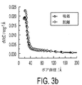
S@C複合材料の合成の第1ステップにおいて、カーボン球状体は、低価格カーボン前駆材料(具体的には、ピッチマテリアル、しかしながら以下にさらに議論されているように、他のカーボン前駆材料は排除される訳ではない)の熱分解により、製造した。当該低価格カーボン前駆材料は、ポーラス金属酸化物テンプレートナノ粒子のポアにおよび当該ポア内において均一に析出する(具体的には、第1の実施の形態に係るシリカテンプレートナノ粒子のTEMイメージに係る図1aおよび第1の実施の形態のカーボン被覆シリカテンプレートナノ粒子のTEMイメージに係る図1b参照)。その後の、シリカテンプレートのナノ粒子サポートの溶解により、良好に規定された中空状カーボンひな形が生成された。これは、図2aのTEMイメージにより説明されている。金属酸化物のテンプレートナノ粒子のサイズおよび気孔率を調整することにより、648m2g−1という高い比表面積(具体的には、図3a参照;一般的には、約100〜約1500m2g−1の特定の表面積範囲に含まれる)、1nmという平均ポア直径(具体的には、図3b参照;一般的には、約0.5〜約20nmのポア直径範囲に含まれる)、大きな内部ボイドスペース(具体的には、図2a参照)を有する中空状のカーボン球状体を容易に製造することができた。当該合成の最終ステップにおいて、比較的低い硫黄の昇華温度を利用して、図4に説明されているように、閉じられた、2つの区分に分離されたチューブの一つの区分に存在するメソポーラス中空状カーボン球状ひな形担持体に、高い圧力で気体状の硫黄を注入した。当該方法は、速く、効率的で、そして制御された、高圧(すなわち、少なくとも約2気圧、より好ましくは少なくとも約5気圧、さらに好ましくは少なくとも約8気圧であるが、より具体的には、約2、5、若しくは8気圧〜約20気圧)での元素硫黄のホストポーラスカーボンひな形への注入を容易にし、少なくとも約0.82gcm−3という高いタップ密度を有するカーボン−硫黄粒子が生成された。この特定の方法は、また、不活性ガス(すなわち、以下に限定される訳ではないが、例えばヘリウム、ネオン、若しくはアルゴン等)の使用が予定されている。不活性ガスは、硫黄の注入と同時に、上述した高い圧力を提供することを助力するため、元素硫黄とともに加熱される。図5において例示されているように、熱質量測定分析により、およそ35%の硫黄がシングルパスにおいて当該粒子に組み込まれうることが示され、3つのパス(気体状の硫黄を中空状のカーボンひな形にさらすことを繰り返すこと)により、ポーラス状の中空カーボンひな形の質量の70%近くが、注入された硫黄から構成される。 In the first step of the synthesis of the S @ C composite material, the carbon spheres are replaced with low-cost carbon precursors (specifically, pitch materials, but other carbon precursors are excluded as discussed further below). Produced by thermal decomposition. The low-cost carbon precursor material is uniformly deposited in and within the pores of the porous metal oxide template nanoparticles (specifically, according to the TEM image of the silica template nanoparticles according to the first embodiment) FIG. 1a and FIG. 1b according to the TEM image of the carbon-coated silica template nanoparticles of the first embodiment). Subsequent dissolution of the silica-templated nanoparticle support produced a well-defined hollow carbon template. This is illustrated by the TEM image in FIG. By adjusting the size and porosity of the metal oxide template nanoparticles, a high specific surface area of 648 m 2 g −1 (see specifically FIG. 3 a; generally from about 100 to about 1500 m 2 g − included in the specific surface area ranging from 1), the average pore diameter (specifically called 1 nm, see Fig. 3b; in general, be included in the pore diameter range of from about 0.5 to about 20 nm), large internal voids A hollow carbon sphere having a space (specifically, see FIG. 2a) could be easily produced. In the final step of the synthesis, a relatively low sulfur sublimation temperature is used, as illustrated in FIG. 4, to close the mesoporous hollow that is present in one section of the tube that is closed into two sections. Gaseous sulfur was injected at a high pressure into a cylindrical carbon spherical pattern carrier. The method is fast, efficient and controlled at high pressure (ie, at least about 2 atmospheres, more preferably at least about 5 atmospheres, more preferably at least about 8 atmospheres, but more specifically, about Facilitated injection of elemental sulfur into the host porous carbon template at 2, 5, or 8 atmospheres to about 20 atmospheres, and produced carbon-sulfur particles having a high tap density of at least about 0.82 gcm −3 . . This particular method is also intended to use an inert gas (ie, but not limited to, for example, helium, neon, or argon). The inert gas is heated with elemental sulfur to help provide the high pressure described above, simultaneously with the sulfur injection. As illustrated in FIG. 5, thermal mass spectrometry analysis shows that approximately 35% of the sulfur can be incorporated into the particles in a single pass, with three passes (gaseous sulfur and hollow carbon By repeating the exposure to shape), nearly 70% of the mass of the porous hollow carbon template is composed of the injected sulfur.
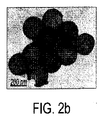
図2aおよび図2bは、硫黄材料注入前および後の典型的な中空状カーボン材料ひな形球状体の透過型電子顕微鏡(TEM)イメージを示している。高い表面積を有し比較的大きなメソポーラスサイズの中空状カーボン材料球状体は魅力的である。これは、Li−S酸化還元反応により発生した電解質およびLiイオンが、中空状の炭素材料球状体を透過できると考えられているからである。中空状のカーボン材料球状体(具体的には、図2bにおける、底部が最も中空状であるカーボン材料球状体参照)の壁部において亀裂が発生する一方、硫黄注入のために使用されるパイレックスチューブ内に発生した圧力は、上述したように、所望の電気化学的特性を提供する方法で中空状のカーボン材料球状体ホストに硫黄を完全に組み込むことを容易にするために必要不可欠である。エネルギー分散型X線(EDX)ミクロ分析により分析されたS@Cナノ複合材料の元素成分が図2(c)に示されている。メソポーラスS@C材料内の異なる位置から収集されたEDXスペクトルは、また、ポーラス中空状カーボン材料球状体に亘って硫黄材料が存在することを示している。 2a and 2b show transmission electron microscope (TEM) images of typical hollow carbon material stationery spheres before and after sulfur material injection. Hollow carbon material spheres having a high surface area and relatively large mesoporous size are attractive. This is because it is believed that the electrolyte and Li ions generated by the Li—S redox reaction can permeate through the hollow carbon material sphere. Pyrex tubes used for sulfur injection while cracks occur in the wall of the hollow carbon material sphere (specifically, in FIG. 2b, the carbon material sphere with the bottom being the most hollow). The pressure generated within, as described above, is essential to facilitate the complete incorporation of sulfur into the hollow carbon material sphere host in a manner that provides the desired electrochemical properties. The elemental components of the S @ C nanocomposite analyzed by energy dispersive X-ray (EDX) microanalysis are shown in FIG. 2 (c). EDX spectra collected from different locations within the mesoporous S @ C material also indicate the presence of sulfur material across the porous hollow carbon material sphere.
元素硫黄は、概して、非常に安定な斜方晶系結晶構造として存在する。図6のx線回折スペクトルにおいて結晶性硫黄に特徴的なピークが存在することは、第1の実施の形態に係るS@Cナノ複合材料において硫黄結晶化の程度が非常に低いことを示している。このことは、昇華され注入された硫黄がアモルファスであること、若しくは、メソポーラス中空状カーボン球状体の最も微細なポアに捕捉された硫黄粒子が結晶化できないことを示している。しかしながら、XRDは、カーボン材料がいくらかの結晶オーダーを有することを示しており、本明細書において考慮された材料についてグラファイトのような特性を示している。相対ピーク領域は、グラファイト面の黒鉛化度若しくは配向度を概算するために分析してもよい。図7に説明されているように、当該分析は、当該材料の38%より多くがグライファイトカーボンであることを示している。1350cm−1および〜1580cm−1それぞれにおけるD-ラマン散乱ピークおよびG-ラマン散乱ピークの相対的強度は、カーボンを特定する方法、その炭素量を評価する既知の代替方法を提供する。カーボン球状体においてD-ラマンバンドおよびG-ラマンバンドの両方が存在することは、図8に示されたラマンスペクトルにおいて制限される。グラファイト含有量は、およそ16%と概算され、2つの概算値間の差異は、図9のラマン較正のより高い不安定性に起因する。グラファイトカーボンの電気伝導率が、アモルファスのカーボンより実質的により高いため、それらが伝導性が悪い注入硫黄から電子を輸送することを容易にできれば、部分的に炭素化されたカーボンひな形ナノ粒子は魅力的であり、このため、より高いディスチャージレートでS@Cナノ複合材料中空状体の電気化学的安定性を助力する。 Elemental sulfur generally exists as a very stable orthorhombic crystal structure. The presence of a characteristic peak in crystalline sulfur in the x-ray diffraction spectrum of FIG. 6 indicates that the degree of sulfur crystallization is very low in the S @ C nanocomposite material according to the first embodiment. Yes. This indicates that the sublimated and injected sulfur is amorphous, or that the sulfur particles trapped in the finest pores of the mesoporous hollow carbon sphere cannot be crystallized. However, XRD indicates that the carbon material has some crystal order and exhibits graphite-like properties for the materials considered herein. The relative peak area may be analyzed to approximate the degree of graphitization or orientation of the graphite surface. As illustrated in FIG. 7, the analysis shows that more than 38% of the material is glyphite carbon. The relative intensities of the D-Raman and G-Raman scattering peaks at 1350 cm −1 and ˜1580 cm −1, respectively, provide a method for identifying carbon, a known alternative method for evaluating its carbon content. The presence of both D-Raman and G-Raman bands in the carbon sphere is limited in the Raman spectrum shown in FIG. The graphite content is estimated at approximately 16%, and the difference between the two estimates is due to the higher instability of the Raman calibration of FIG. Because graphite carbon has a substantially higher electrical conductivity than amorphous carbon, partially carbonized carbon stationery nanoparticles can be used if they can easily transport electrons from poorly conductive injected sulfur. It is attractive and thus helps the electrochemical stability of S @ C nanocomposite hollow bodies at higher discharge rates.
S@Cナノ複合材料を組み込んだ電極のサイクリックボルタモグラム(CV)が図10aに示されている。一対のシャープな酸化還元ピークが存在することは、チャージ/ディスチャージ中、2つのステージにおいて硫黄の電気化学的還元と酸化とが起こることを示している。2.4Vにおける第1のピーク(IIで示されている)は、元素硫黄のリチウムポリ硫化物(Li2Sn、4≦n≦8)に対する還元を含む。2.0Vにおける第2のピーク(IIIで示されている)は、リチウムポリ硫化物中の硫黄の、Li2S2、最終的にLi2Sに対する還元を含む。Li−Sセルにおける酸化プロセスは、また、2つのステージにおいて起こる。2.35Vにおける酸化ピーク(II'で示されている)は、Li2Sn(n>2)の形成と関連する。当該プロセスは、リチウムポリ硫化物が完全に消費されるまで続けられ、2.45Vにおいて元素硫黄が生成される(III'で示される)。重要なことは、CVピークポジション若しくはピーク電流(図10aに示されている)において変化がないことが60スキャン後でさえも観察されることである。このことは、S@Cナノ複合材料の電気化学的安定性を裏付けるものであり、ポーラスカーボン構造が、電解質への硫黄の質量損失を抑制し、酸化還元反応において、活性な硫黄の高い利用性を維持する際極めて効果的であることを示している。 A cyclic voltammogram (CV) of an electrode incorporating an S @ C nanocomposite is shown in FIG. 10a. The presence of a pair of sharp redox peaks indicates that electrochemical reduction and oxidation of sulfur occur in two stages during charge / discharge. The first peak at 2.4 V (shown as II) involves the reduction of elemental sulfur to lithium polysulfide (Li 2 Sn , 4 ≦ n ≦ 8). The second peak at 2.0 V (shown in III) involves the reduction of sulfur in the lithium polysulfide to Li 2 S 2 and ultimately Li 2 S. The oxidation process in Li-S cells also occurs in two stages. Oxidation peak at 2.35V (indicated by II ') is associated with the formation of Li 2 S n (n> 2 ). The process continues until the lithium polysulfide is completely consumed, and elemental sulfur is produced at 2.45 V (denoted III ′). Importantly, no change in CV peak position or peak current (shown in FIG. 10a) is observed even after 60 scans. This confirms the electrochemical stability of S @ C nanocomposites, and the porous carbon structure suppresses the mass loss of sulfur to the electrolyte, and the high availability of active sulfur in redox reactions. It is extremely effective in maintaining
図10bは、当該S@Cナノ複合材料を組み込んだ電極についての、典型的なディスチャージ/チャージ電圧プロファイルを示している。II, IV,II', IV'とマークされたディスチャージ/チャージ電圧プラトーがII, IV,II', IV'とマークされたCVスキャンにおいて観察された酸化還元ピークと確かに共通性がある。対応するチャージプラトーおよび反応は当該明細書において確認されているけれども、CV実験において観測された2.45Vにおける酸化ピークは、以前では報告されていない;すなわち、ここで、その存在は、S@Cナノ複合材料において起こる電気化学的反応の可逆性を上手く補強する。図10bにおいて示されているように、調製されたS@Cナノ複合材料は、1071mAhg−1の最初の比ディスチャージキャパシティーを示し、100サイクル後の91%キャパシティー保持率で974mAhg−1(0.5Cのレート)という可逆的キャパシティーを維持する。完全を期すため、図11cは、S@C複合材料の制限された質量に基づく、対応する比キャパシティーを報告している。図11cから、それぞれの測定により、意図されたバッテリーアプリケーションの観点から比キャパシティー値が魅力的であることが明らかである。さらに、100回のサイクル後、電圧プラトーにおいて変化が見られない。これは、セルの延長サイクルの間、実質的に変化しないことを示している。これは、また、バッテリーアプリケーションにとって望ましい。 FIG. 10b shows a typical discharge / charge voltage profile for an electrode incorporating the S @ C nanocomposite. The discharge / charge voltage plateaus marked II, IV, II ′, IV ′ are indeed in common with the redox peaks observed in the CV scans marked II, IV, II ′, IV ′. Although the corresponding charge plateau and reaction have been confirmed in the specification, the oxidation peak at 2.45 V observed in CV experiments has not been reported previously; that is, where its presence is S @ C It successfully reinforces the reversibility of electrochemical reactions that occur in nanocomposites. As shown in FIG. 10b, it was prepared S @ C nanocomposite materials exhibit initial ratio discharge capacity of 1071mAhg -1, 974mAhg -1 (0 91% capacity retention after 100 cycles A reversible capacity of .5C). For completeness, FIG. 11c reports the corresponding specific capacity based on the limited mass of the S @ C composite. From FIG. 11c, it is clear from each measurement that the specific capacity value is attractive in terms of the intended battery application. Furthermore, after 100 cycles, there is no change in the voltage plateau. This indicates that there is substantially no change during the cell extension cycle. This is also desirable for battery applications.
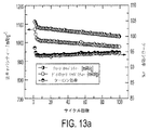
図12は、非常に高い電流レートにおいて、ディスチャージプラトーおよびチャージプラトーが同じパターンを示す材料に関して電圧プロファイルを報告する。S@Cナノ複合材料の速度能力およびサイクルライフ挙動は、図13aおよび図13bにおいて、より詳細に考慮されている。具体的には、図13aは、延長サイクル時減衰するいくつかのキャパシティーが存在することを示しており、しかしながら、延長サイクル時、Li−Sセルの劇的なキャパシティー還元特性についての証拠を示していない。可逆的なLi−S8酸化還元反応は、非トポタキシー同化プロセスを介して起こるため、ホストであるカーボン構造に組み込まれた硫黄による体積膨張およびその後のディスチャージ/チャージ反応は小さいと予想される。一方、図11aおよび図11bに示された新品の硫黄のチャージ−ディスチャージ挙動は、ディスチャージキャパシティーにおける顕著な減少、シャトルメカニズムについての不完全なチャージング特性を示す。 FIG. 12 reports the voltage profile for materials where the discharge plateau and charge plateau exhibit the same pattern at very high current rates. The speed capability and cycle life behavior of S @ C nanocomposites are considered in more detail in FIGS. 13a and 13b. Specifically, FIG. 13a shows that there is some capacity decaying during the extended cycle; however, there is evidence for the dramatic capacity reduction characteristics of the Li-S cell during the extended cycle. Not shown. Since the reversible Li-S 8 redox reaction occurs via a non-topotaxy assimilation process, the volume expansion and subsequent discharge / charge reaction due to sulfur incorporated into the host carbon structure is expected to be small. On the other hand, the new sulfur charge-discharge behavior shown in FIGS. 11a and 11b shows a significant reduction in discharge capacity, incomplete charging characteristics for the shuttle mechanism.
一旦シャトルメカニズムが始まると、図11aに示すように、約2.4Vにおけるチャージング挙動が、オーバーチャージすることなく続き、チャージおよびディスチャージキャパシティーの終端におけるチャージ効率が減少することになる。第1サイクルにおけるS@Cナノ複合材料のクーロン効率は、100サイクル後の94%と比較して96%と概算され、これは信頼性のある安定性を示している。これに対して、第1サイクルにおける従来の硫黄(図11b)のクーロン効率は、77%と概算され、8サイクルの終わりまでに31%まで減少する。従来の材料は、電解液においてポリ硫化物の濃度が増加するため、その後、既知の連続するチャージプロセスを示す。より高いレートにおけるS@Cナノ複合材料の速度能力挙動が、図13bに示されている。実験された最大ディスチャージレートにおいて(3C(5.1A/g))、当該材料は、450mAhg−1伝達されると見られる。これは、この高いレートにおいてリサイクルされるLi−S二次バッテリーについての前例のない結果である。カソード材料の安定性は、また、0.5Cレートにおいて891mAhg−1のキャパシティーをリカバリーし、(Li−Sセルについての)3Cという高いレートにおいてチャージすることによって証明されている(図13b)。 Once the shuttle mechanism begins, the charging behavior at about 2.4V continues without overcharging, as shown in FIG. 11a, and the charge efficiency at the end of charge and discharge capacity will decrease. The Coulomb efficiency of the S @ C nanocomposite in the first cycle is estimated to be 96% compared to 94% after 100 cycles, which indicates reliable stability. In contrast, the coulombic efficiency of conventional sulfur in the first cycle (FIG. 11b) is estimated to be 77% and decreases to 31% by the end of 8 cycles. Conventional materials then exhibit a known continuous charge process due to the increased concentration of polysulfide in the electrolyte. The speed capability behavior of S @ C nanocomposites at higher rates is shown in FIG. 13b. At the maximum discharge rate tested (3C (5.1 A / g)), the material appears to deliver 450 mAhg- 1 . This is an unprecedented result for Li-S secondary batteries recycled at this high rate. The stability of the cathode material has also been demonstrated by recovering a capacity of 891 mAhg −1 at 0.5 C rate and charging at a high rate of 3 C (for Li-S cells) (FIG. 13 b).
調製されたS@Cナノ複合材料の優れた全電気化学的挙動は、それらのデザインから発生する複数の可能性として考えられる相乗的要因に起因する。第一に、メソポーラスの高表面積カーボンホストは、吸着するカーボンフレームワーク上に、並びにその中に高レベルの硫黄が析出することを容易にする。当該材料の非常に優れた電気化学的安定に基づいて、当該フレームワークのポアおよび内部ボイドスペース内に硫黄を限定することにより、電解質に対するリチウムポリ硫化物の損失を最小にし、シャトリングを低減すると考えられる。第二に、カーボンフレームワークの部分的グラファイト特性は、析出された硫黄フィルムに対して機械的な安定性を提供すると信じられており、また、導電性の弱い活性材料から/当該伝導性の弱い活性材料への実効的な電子の輸送を可能とする。当該後者の特徴は、高い電流密度において当該材料の電気化学的安定性の原因であると考えられる、すなわち、カーボンひな形のグラファイト含有量が減少するに従って、改善されると期待される。最後に、当該フレームワークにおけるポアは、電解液が容易にアクセスすることができ、活性材料に対するL+イオンの早い輸送を維持する程十分大きい。 The excellent overall electrochemical behavior of the prepared S @ C nanocomposites is due to multiple possible synergistic factors arising from their design. First, the mesoporous high surface area carbon host facilitates the deposition of high levels of sulfur on and in the adsorbing carbon framework. Based on the very good electrochemical stability of the material, limiting the sulfur in the framework pores and internal void spaces minimizes the loss of lithium polysulfide to the electrolyte and reduces shuttling. Conceivable. Secondly, the partial graphite properties of the carbon framework are believed to provide mechanical stability to the deposited sulfur film, and also from / being weakly conductive active materials. Enables effective transport of electrons to the active material. The latter feature is believed to be responsible for the electrochemical stability of the material at high current densities, i.e. it is expected to improve as the graphite content of the carbon template decreases. Finally, the framework Contact Keru the pores may be electrolyte easily access, sufficiently large enough to maintain a fast transport of L + ions to the active material.
つまり、容易に入手可能であり拡張可能な方法が、メソポーラス中空状カーボンひな形に基づくS@Cナノ複合材料を合成するために上のように記載されている。当該方法は、所望の特徴、高い圧力を有し、早く効率的な元素硫黄の立ち上がりを発生させるためカーボンひな形のポアおよびセンターに元素硫黄を気相注入された中空状カーボンひな形粒子を合成するための、テンプレートベースアプローチを用いる。Li−S二次バッテリーにおいてカソード材料として評価されるとき、調製されたS@Cナノ複合材料は、低い電流密度および高い電流密度の両方において傑出した電気化学的特性を示す。ここに記載された材料は、二次Li−Sバッテリーにおいて延長サイクルライフおよび高いチャージレート性能を提供する最初のものである。これらの観測は、カーボンひな形に元素の硫黄が閉じ込められること、ポリ硫化物シャトルリングを限定する際の好適な影響、並びにカーボンフレームワークとの密接な接触により可能とされた伝導性の弱い硫黄からの電子輸送が向上されたことに由来する。 That is, a readily available and expandable method is described above for synthesizing S @ C nanocomposites based on mesoporous hollow carbon templates. The method synthesizes hollow carbon template particles that have the desired characteristics, high pressure, and in which the elemental sulfur is vapor-injected into the pores and the center of the carbon template to quickly and efficiently generate elemental sulfur rising. Use a template-based approach to When evaluated as a cathode material in Li-S secondary batteries, the prepared S @ C nanocomposites exhibit outstanding electrochemical properties at both low and high current densities. The materials described here are the first to provide extended cycle life and high charge rate performance in secondary Li-S batteries. These observations indicate that elemental sulfur is trapped in the carbon template, the favorable effect of limiting the polysulfide shuttle ring, and the poorly conductive sulfur enabled by close contact with the carbon framework. This is because the electron transport from is improved.
A.実験の詳細
メソポーラス中空状カーボン球状体は、ハードテンプレートアプローチにより調製した。典型的な合成において、従来の方法により合成された高度に多孔質のシリカテンプレート(2g)を、1.05gの石油ピッチ(カーボニックス、韓国)を含有する、50mlのN−メチル−2−ピロリドン(NMP、アルドリッチ)溶液中に分散させた。分散液は、20分間超音波分解し、110℃で、蒸留、および完全な溶媒除去のためのロータリーエバポレーターに移送した。その後、石油ピッチでコートしたシリカ粒子を110℃で12時間真空乾燥し、続いて、アルゴンフロー下12時間1300℃で焼成した。この段階で得られたカーボンコートシリカ粒子は、HF(アルドリッチ)で処理して、シリカテンプレートをエッチング除去し、その後水およびエタノールにより洗浄した後乾燥させた。高圧気相注入法を用いて硫黄注入を実行した。
A. Experimental Details Mesoporous hollow carbon spheres were prepared by a hard template approach. In a typical synthesis, a highly porous silica template (2 g) synthesized by conventional methods is replaced with 50 ml of N-methyl-2-pyrrolidone containing 1.05 g of petroleum pitch (Carbonix, Korea). (NMP, Aldrich) dispersed in solution. The dispersion was sonicated for 20 minutes, transferred to a rotary evaporator at 110 ° C. for distillation and complete solvent removal. Thereafter, silica particles coated with petroleum pitch were vacuum-dried at 110 ° C. for 12 hours, and then calcined at 1300 ° C. for 12 hours under an argon flow. The carbon-coated silica particles obtained at this stage were treated with HF (Aldrich) to remove the silica template by etching, then washed with water and ethanol and then dried. Sulfur injection was performed using high pressure gas phase injection.
S@Cカソードスラリーを92.5%の複合材料(70%の硫黄と30%のカーボン中空状球状体)および7.5%のPVDFバインダーをNMP溶媒分散剤において混合することにより作製した。当該スラリーでアルミニウムホイルをコートし、12時間120℃で乾燥させることにより、正極を作製した。結果として得られたスラリーコートアルミニウムホイルは、ロールプレスされ、当該電極を、パンチング装置を用いて所望の大きさまで小型化した。作製された全電極の電極厚さは、当該ロールプレスにより、本来の厚さの85%まで減少させたものと同じ(〜80μm)であった。同じ手順を続けて、従来の硫黄カソードを作製した(当該カソードスラリーは、NMP分散剤における、80%の元素硫黄、10%のスーパーP伝導性カーボンおよび10%PVDFバインダーからなることを除く)。予備のセルテストを2032コインタイプのセルについて実行した。これは、カウンター電極としてリチウム金属を使用しそしてマイクロポーラスポリエチレンセパレータを使用してアルゴン充填されたグローブボックス内において製造された。電解溶液は、テトラグリムに溶解された1Mリチウムビス(トリフルオロメタンスルホン)イミド(LiTFSI)であった。サイクリックボルタメトリーの調査をソーラートロンセルテストモデルポテンシオスタットについて実行した。ポテンシャルウィンドウ3.1〜1.7Vの下での電気化学的チャージディスチャージ分析をマッコーサイクルライフテスターを用いて実行した。 An S @ C cathode slurry was made by mixing 92.5% composite (70% sulfur and 30% carbon hollow spheres) and 7.5% PVDF binder in NMP solvent dispersant. An aluminum foil was coated with the slurry and dried at 120 ° C. for 12 hours to produce a positive electrode. The resulting slurry coated aluminum foil was roll pressed and the electrodes were downsized to the desired size using a punching device. The electrode thickness of all the produced electrodes was the same as that reduced to 85% of the original thickness by the roll press (˜80 μm). The same procedure was followed to make a conventional sulfur cathode (except that the cathode slurry consists of 80% elemental sulfur, 10% super P conductive carbon and 10% PVDF binder in NMP dispersant). A preliminary cell test was performed on a 2032 coin type cell. This was produced in a glove box filled with argon using lithium metal as a counter electrode and using a microporous polyethylene separator. The electrolytic solution was 1M lithium bis (trifluoromethanesulfone) imide (LiTFSI) dissolved in tetraglyme. Cyclic voltammetry studies were performed on the Solartron Cell test model potentiostat. Electrochemical charge discharge analysis under a potential window of 3.1-1.7V was performed using a McCaw cycle life tester.
B.他のソースからの硫黄材料注入カーボン材料ナノ複合材料に関連する考察
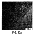
メソポーラス中空状カーボン硫黄複合材料を石油ピッチから作製するために使用される高圧気相注入アプローチを用いハイパワー硫黄電極を作製した。この際、他のカーボンソース(通常バルクのソース(例えば、石炭、高濃度硫黄石炭、木炭、および有機ポリマーエアロゲル))を使用する。例えば、図14、図22および図23は、不活性の大気環境においてレゾルシノールホルムアルデヒドポリマーエアロゲルを熱分解することにより得られた市販のカーボン前駆物質を使用して得られた結果を纏めている。当該材料は、アメリカンエアロゲルにより無償で提供され、絶縁性製品のため流通する。当該カーボン材料は、始め、不活性(アルゴン)雰囲気において、1000〜1250℃の範囲の温度で活性化された。図22Aはカーボンエアロゲル材料の透過型電子顕微鏡イメージを示しており、これは、続く炭化が実態のないものであることを示している(すなわち、当該材料は、上述したカーボン球状体のナノ構造を示していない)。図22Bは、中空状のカーボン材料球状体に硫黄を注入するための上述の方法に係る、硫黄注入後のカーボンエアロゲルの透過型電子顕微鏡イメージを示す。
B. Considerations Related to Sulfur-Material-Injected Carbon Material Nanocomposites from Other Sources High-power sulfur electrodes were fabricated using the high-pressure gas-phase injection approach used to fabricate mesoporous hollow carbon-sulfur composites from petroleum pitch. In this case, other carbon sources (usually bulk sources such as coal , high-concentration sulfur coal , charcoal , and organic polymer airgel) are used. For example, FIGS. 14, 22 and 23 summarize the results obtained using commercially available carbon precursors obtained by pyrolyzing resorcinol formaldehyde polymer airgel in an inert atmospheric environment. The material is provided free of charge by American Airgel and is distributed for insulating products. The carbon material was first activated at a temperature in the range of 1000 to 1250 ° C. in an inert (argon) atmosphere. FIG. 22A shows a transmission electron microscope image of a carbon aerogel material, which indicates that the subsequent carbonization is impractical (ie, the material exhibits the carbon sphere nanostructure described above. Not shown). FIG. 22B shows a transmission electron microscope image of carbon aerogel after sulfur injection according to the method described above for injecting sulfur into a hollow carbon material sphere.
図23および図14aは、図22Bの硫黄注入カーボン材料フォームレスマスを磨り潰すことにより形成されるナノ粒子を示している。これらの結果として得られる硫黄注入カーボンナノ粒子は、上述した中空状カーボンナノ粒子球状体の大きさと同じであり、それらは、同様の方法および材料を使用して組み立てカソード電極とした。 FIGS. 23 and 14a show nanoparticles formed by grinding the sulfur-implanted carbon material foamless mass of FIG. 22B. These resulting sulfur-implanted carbon nanoparticles were the same size as the hollow carbon nanoparticle spheres described above, and they were assembled into cathode electrodes using similar methods and materials.
図14B〜14Eは、当該付加的な硫黄注入ナノ粒子カーボン材料が、上述した中空状カーボン球状体を有する複数の特徴を共有する。 14B-14E share the multiple features of the additional sulfur-implanted nanoparticulate carbon material having the hollow carbon spheres described above.
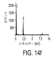
特に、図14Bおよび図14Cは、BETポロシメトリー測定からの結果であり、これは、当該材料が、高い比表面積(257m2/g)を有し、小さい平均粒径(3.8nm)を有することを示している。図14Dおよび図14Eは、当該材料についてのラマン散乱スペクトルおよび広角X線回折スペクトルである。ラマン散乱スペクトルにおいてGバンドが存在すること、および、広角X線回折スペクトルにはっきりと分かるピークが存在することは、当該材料が結晶性であることを意味している。図14Eの上部のプロットは、中空状カーボン球状体について使用された同じ気相硫黄注入法を用いて硫黄注入した後の当該材料のX線回折スペクトルである。硫黄注入後の当該材料のエネルギー分散X線(EDX)スペクトルが図14Fに示されている。これは、カーボンおよび硫黄のみを含んで成る(すなわち、カーボンおよび硫黄のみからなる)ことを示している。そのため、図14Eにおける上部プロットは、吸着された硫黄がアモルファスであることを意味する。ラマンおよびXRDのデータの定量分析は、カーボンの少なくとも10%がグラファイト性であることを意味する。 In particular, FIG. 14B and FIG. 14C are the results from BET porosimetry measurements, where the material has a high specific surface area (257 m 2 / g) and a small average particle size (3.8 nm). It is shown that. 14D and 14E are the Raman scattering spectrum and the wide-angle X-ray diffraction spectrum for the material. The presence of the G band in the Raman scattering spectrum and the clearly visible peak in the wide-angle X-ray diffraction spectrum mean that the material is crystalline. The top plot of FIG. 14E is an X-ray diffraction spectrum of the material after sulfur injection using the same gas phase sulfur injection method used for hollow carbon spheres. The energy dispersive X-ray (EDX) spectrum of the material after sulfur implantation is shown in FIG. 14F. This indicates that it contains only carbon and sulfur (ie, consists only of carbon and sulfur). Therefore, the upper plot in FIG. 14E means that the adsorbed sulfur is amorphous. Quantitative analysis of Raman and XRD data means that at least 10% of the carbon is graphitic.
S/C複合材料の熱質量測定は、当該材料の質量の59%が硫黄であることを示している。図14Gおよび図14Hに説明されているように、(特に)サイクリックボルタメトリー測定および関連する電気化学的測定により、アメリカンエアロゲルを使用して得られた当該S/C複合材料は、電気化学的に安定で、あらゆる点から考えて、上述したメソポーラス中空状カーボン球状体を使用して得られたS/C複合材料と同じであることが示されている。図14Iは、当該材料が、リチウム金属をアノードとして用いるコインセルにおいてカソードとして使用されるときに達成された0.5Cのチャージレートにおけるエネルギー貯蔵キャパシティーを示している。図14Iのデータは、600以上のチャージ−ディスチャージサイクル後、当該材料が600mAh/gを超えるキャパシティーを移動させることを示している。S/C複合材料カソードの比容量および容量保持は、カーボン球状体について観測されたものより少し低いが、当該差異は、(具体的にはマルチパスを使用して)硫黄注入のレベルを増加させることにより、容易に除去できるであろうと推測される。 Thermal mass measurement of the S / C composite material indicates that 59% of the mass of the material is sulfur. As illustrated in FIGS. 14G and 14H, the S / C composite material obtained using American aerogel by (among other things) cyclic voltammetry measurements and related electrochemical measurements is It is shown that it is the same as the S / C composite material obtained by using the above-described mesoporous hollow carbon sphere in all respects. FIG. 14I shows the energy storage capacity at a charge rate of 0.5 C achieved when the material is used as the cathode in a coin cell using lithium metal as the anode. The data in FIG. 14I shows that after more than 600 charge-discharge cycles, the material moves capacity greater than 600 mAh / g. The specific capacity and capacity retention of the S / C composite cathode is slightly lower than that observed for the carbon spheres, but the difference increases the level of sulfur injection (specifically using multipass). It is assumed that it can be easily removed.
S/C複合材料粒子は、他の様々なカーボンソース(ポリアクリロニトリル(PAN)、多糖(具体的にはグルコース)、クエン酸、没食子酸、桂皮酸、およびポリマー性コア(具体的には、ポリスチレン、ポリメチルメタクリレート))を使用して作製しうる。高温の熱分解に続いて、高圧の気相注入により、>50%の硫黄が注入され、S/C中空球状粒子に匹敵する電気化学的性能を有するS/C複合材料が作製される。 S / C composite particles consist of various other carbon sources (polyacrylonitrile (PAN), polysaccharides (specifically glucose), citric acid, gallic acid, cinnamic acid, and polymeric cores (specifically polystyrene). , Polymethylmethacrylate)). Following high temperature pyrolysis, high pressure gas phase injection injects> 50% sulfur to produce S / C composites with electrochemical performance comparable to S / C hollow spherical particles.
S/C複合材料を作製するために使用された同じアプローチを他の、より広く普及したカーボン材料(具体的には石炭)に対しても適用可能である。特に、石炭(理想的には高い硫黄を有するもの)が、熱処理後、少なくとも5質量%のグラファイトカーボンを含む場合、電気化学的および/または機械的に磨り潰すことを用いて、上述のテンプレートプロセッシングに適用可能な高表面積ナノサイズ化カーボン粒子を作製してもよい。高圧気相注入法を使用して、上述した中空状カーボンひな形材料と同じエネルギー密度および電気化学的サイクル安定性を有するS/C複合材料を作製することができる。 The same approach used to make S / C composites can be applied to other more widely used carbon materials (specifically coal ). In particular, if the coal (ideally having high sulfur) contains at least 5% by weight of graphite carbon after heat treatment, the above-described template processing may be performed using electrochemical and / or mechanical grinding. High surface area nano-sized carbon particles applicable to the above may be prepared. A high pressure gas phase injection method can be used to produce S / C composites having the same energy density and electrochemical cycle stability as the hollow carbon template material described above.
II.加硫処理されたポリマルチエンポリマー材料およびイオン伝導性ポリマー材料を含有する、硫黄含有ナノ粒子
第二の実施の形態は、リチウムイオンバッテリー内のカソードにおいて硫黄を捕捉および隔離するための新規な材料を記載する。このような材料の基本構造は、多くのポリブタジエン(PBD)(すなわち、より一般的にはポリマルチエンポリマー材料)、ポリエチレングリコール(PEG)(すなわち、より一般的にはイオン伝導性ポリマー材料)ジブロックコポリマーストランドにより架橋されたコアにおけるシリカ(もしくは他の金属酸化物)粒子である。当該PBDは、硫黄とクロスリンクされ、当該シリカ(もしくは他の金属酸化物)粒子に束縛された流動するポリマーストランドは、硫黄の捕捉を助力する。PBDが非常に低い伝導性を有することが知られているため、非常に高い伝導性を有するPEGがPBDに架橋されることにより、シリカ粒子の周りにジブロックコポリマーのシェルが形成される。記載された構造は、NOHMS(ナノ粒子有機ハイブリッド材料システム)のものである。NOHMSは、有機ポリマーデンドライトを、シリカのようなコア材料に結合させる新規な材料構造である。コア材料は、単純に、アンカーとして機能し、その周りにおいてデンドライトシェル層を形成してもよいし、もしくは、それ自身の特定の性能を提供してもよい。多成分系ハイブリッド材料が、ナノスケールにおいていくつかの成分の特性を組み合わせることにより相乗効果をもたらす。この第二の実施の形態について、上述のNOHMS構造は、当該デンドライトが、拡散をやや難しくする機能を有するため、当該カソード近くの領域を去る硫黄を捕捉することを高める。
II. Sulfur-containing nanoparticles containing a vulcanized polymultiene polymer material and an ion conducting polymer material A second embodiment is a novel method for capturing and sequestering sulfur at the cathode in a lithium ion battery. List the materials. The basic structure of such materials is a number of polybutadiene (PBD) (ie, more commonly polymultiene polymer materials), polyethylene glycol (PEG) (ie, more commonly ion conductive polymer materials) diblocks. Silica (or other metal oxide) particles in the core cross-linked by copolymer strands. The PBD is cross-linked with sulfur and the flowing polymer strands constrained to the silica (or other metal oxide) particles help to capture the sulfur. Since PBD is known to have very low conductivity, PEG with very high conductivity is cross-linked to PBD to form a diblock copolymer shell around the silica particles. The structure described is that of NOHMS (Nanoparticle Organic Hybrid Material System). NOHMS is a novel material structure that binds organic polymer dendrites to a core material such as silica. The core material may simply function as an anchor, form a dendrite shell layer around it, or provide its own specific performance. Multi-component hybrid materials provide a synergistic effect by combining the properties of several components at the nanoscale. About this 2nd embodiment, since the said NOHMS structure has the function in which the said dendrite makes diffusion somewhat difficult, it raises capturing of the sulfur which leaves the area | region near the said cathode.
図15において説明するように、合成スキームは、第二の実施の形態に係るシリカ/PBD/硫黄/PEGナノ粒子を作製する際に用いられる全プロセスを示す。最初に、アミノ官能化シリカ粒子を、修正されたストバープロセスを利用することにより合成した。シリカ最外層をアミノ基で官能化するため、3−トリメトキシシリプロピル−ジエチレントリアミンを使用した。また、シリカ粒子の凝集を低減するため、ポリエチレングリコールメチルエーテルをシランとともに使用した。ナノ粒子のサイズを制御するため、異なる量のアンモニウムハイドロキサイドを使用した。その後、アミン官能化シリカ粒子を、アンカーとして使用し、ジカルボキシ終端ポリブタジエンストランドを結合させた。単官能化ポリエチレングリコールをその後自由なカルボキシ自由端に結合させた。当該プロセスを、N,N−ジメチルフォルムアミドを溶剤として使用して実行した。官能化のレベルのオーダーおよびコア金属酸化物材料に対するPBD材料およびPEG材料を付着させる順序を入れ替える代替の合成スキームが検討されている。さらに、必要とされているように、PBD材料およびPEG材料の特定のタイプの化学的機能をそれに応じて調整および選択することができる。 As illustrated in FIG. 15, the synthesis scheme shows the entire process used in making the silica / PBD / sulfur / PEG nanoparticles according to the second embodiment. Initially, amino functionalized silica particles were synthesized by utilizing a modified Stover process. 3-Trimethoxysilylpropyl-diethylenetriamine was used to functionalize the outermost silica layer with amino groups. Further, polyethylene glycol methyl ether was used together with silane in order to reduce aggregation of silica particles. Different amounts of ammonium hydroxide were used to control the size of the nanoparticles. Amine-functionalized silica particles were then used as anchors to bind dicarboxy terminated polybutadiene strands. Monofunctional polyethylene glycol was then attached to the free carboxy free end. The process was performed using N, N-dimethylformamide as a solvent. Alternative synthetic schemes are being considered that reverse the order of functionalization and the order of attaching the PBD and PEG materials to the core metal oxide material. Furthermore, as required, the specific types of chemical functions of the PBD material and the PEG material can be adjusted and selected accordingly.
図16は、アミノ基官能化されたシリカ粒子についての滴定曲線を示している。当量点は、アミノ官能化が、シリカ粒子1mgに対して5.33×10⁻⁷モルであることを示している。当該アミノ基は、シランに起因し、それらは、シリカ粒子の最外コアを囲む。アミノ官能化された最外層は、変更されていないストバープロセスにより形成された水酸基最外層の代わりに作製した。これは、ジカルボキシルポリブタジエンが、アミノ基と良好に結合されるからである。 FIG. 16 shows a titration curve for amino group functionalized silica particles. The equivalence point indicates that the amino functionalization is 5.33 × 10 −7 mol per 1 mg of silica particles. The amino groups are attributed to silanes, which surround the outermost core of the silica particles. The amino functionalized outermost layer was made in place of the hydroxyl outermost layer formed by an unmodified Stover process. This is because dicarboxyl polybutadiene binds well with amino groups.
シリカ粒子の粒径分布測定により、平均サイズが49.9ナノメートルであり、ナンバーPSDが31.3ナノメートルであり、インテンシティーPSDが62.4ナノメートルであり、PDIが0.204であることが示された。ゼータ電位は、標準偏差18.8mV、伝導率0.447ms/cm、実効電圧147.6ボルトおよび計数率45.3kcpsの場合、−16.5mVであり、当該粒子は凝集しないことを示している。また、純粋シリカ粒子のゼータ電位が−31mVであるので、表面構造が帯電していると理解される。標準偏差は、いくらかの粒子が、正のゼータ電位を有することを示している可能性があるけれども、NaOHは、合成の間添加され、凝集を最小化した。さらに、NaOHは、シリカ粒子とメタノール溶媒との間の水素結合相互作用を低下させるという他の目的を有していた。当該水素結合相互作用は、ゲルの形成を引き起こす。 According to the particle size distribution measurement of silica particles, the average size is 49.9 nanometers, the number PSD is 31.3 nanometers, the intensity PSD is 62.4 nanometers, and the PDI is 0.204. It was shown that. The zeta potential is -16.5 mV when the standard deviation is 18.8 mV, the conductivity is 0.447 ms / cm, the effective voltage is 147.6 volts, and the count rate is 45.3 kcps, indicating that the particles do not aggregate. . Moreover, since the zeta potential of the pure silica particles is −31 mV, it is understood that the surface structure is charged. Although standard deviation may indicate that some particles have a positive zeta potential, NaOH was added during synthesis to minimize aggregation. Furthermore, NaOH had the other purpose of reducing the hydrogen bonding interaction between silica particles and methanol solvent. The hydrogen bonding interaction causes gel formation.
ゼータサイザーからの粒子サイズデータはTEMを使用して確認した。図17は、アミノ官能化されたシリカナノ粒子のTEMイメージを示している。図17は、多くの粒子が15〜45nmの範囲にあることを示している。60nmより大きい直径を有する粒子を探すのは困難であった。合成の間、添加した水酸化アンモニウムの量は、概して、シリカ粒子の特定のサイズを達成することを決定するものであった。2mlのNH4OH:3mlのTEOSの添加により、粒径は5〜10nmとなり、一方、3mlのNH4OH:3mlのTEOSの添加により、粒径は60〜70nmとなった。およそ30nmの粒子サイズは、一の粒子当たり十分なアミノ官能基を有する粒子を含有し、シリカの比率を小さく維持しつつ、シリカNOHMS粒子の流体挙動を達成するように選択した。 Particle size data from the Zetasizer was confirmed using TEM. FIG. 17 shows a TEM image of amino functionalized silica nanoparticles. FIG. 17 shows that many particles are in the range of 15-45 nm. It was difficult to find particles with a diameter greater than 60 nm. During synthesis, the amount of ammonium hydroxide added generally determined to achieve a particular size of silica particles. By adding 2 ml NH 4 OH: 3 ml TEOS, the particle size became 5-10 nm, while by adding 3 ml NH 4 OH: 3 ml TEOS, the particle size became 60-70 nm. A particle size of approximately 30 nm was selected to achieve the fluid behavior of silica NOHMS particles while containing particles with sufficient amino functionality per particle and keeping the silica ratio small.
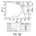
図18のTGAグラフは、ポリマーリンクされたシリカナノ複合材料粒子の組成を示している。図18aにおいて、当該化合物について3つのピークが存在する。第1のピークは、物理吸着水およびDMFである。これらは、合成の間、溶媒として使用した。 The TGA graph of FIG. 18 shows the composition of polymer-linked silica nanocomposite particles. In FIG. 18a, there are three peaks for the compound. The first peak is physically adsorbed water and DMF. These were used as solvents during the synthesis.
当該溶媒は、広範囲の乾燥プロセス(70℃においてオーブンにて48時間、フリーズドライヤーにて24時間)により除去したけれども、水およびDMFの全部が除去されたわけではない。しかしながら、PBDは、より高温で架橋するため、温度は上昇しないであろう。第二のピークは、シリカ粒子を囲繞するシランによるものである。シリカ粒子のTGAのみが、シラン分解温度を示す400℃当たりにピークを示した。熱的に吸着される第三の化合物はPBDであり、550℃とした後に残る化合物はシリカコア粒子である。 Although the solvent was removed by a wide range of drying processes (oven at 70 ° C. for 48 hours, freeze dryer for 24 hours), not all of the water and DMF were removed. However, the temperature will not increase because PBD crosslinks at higher temperatures. The second peak is due to the silane surrounding the silica particles. Only the TGA of the silica particles showed a peak around 400 ° C. indicating the silane decomposition temperature. The third compound thermally adsorbed is PBD, and the compound remaining after 550 ° C. is silica core particles.
図18bは、PEG600をシリカ−PBDナノ複合材料粒子に対して架橋した後のTGAグラフである。PEG600ポリマーは、分解温度を有し、当該分解温度はシランのものと重なっている。第二ピークは、シランおよびPEG600の両方を示している。シリカとシランとの間の相対比率は知られているため、当該ナノ複合材料におけるPEG600の量が推定されるであろう。PEG600に対するPBDの比率は、およそ1に対して7であり、これは、それらのモル重量間の比率である。これは、PEG600が良好に分配され、PBD粒子とPEG粒子とがリンクされていることを示しているであろう。
図18cは、シリカ−PBDナノ複合材料粒子に対してPEG2000を架橋した後のTGAグラフである。当該PEGは、分解温度を有しており、当該分解温度は、シランのものと重なっているが、しかしながらその強度はかなり大きい。PEG2000の量は、また、第二のピークからシランの量を推定することにより概算した。PEG2000のモル重量は、PBDのものより低いけれども、重量比率は同じである。付加的な遠心分離ステップによりPEG2000の含有量は減少するであろう。
FIG. 18b is a TGA graph after cross-linking
FIG. 18c is a TGA graph after cross-linking PEG2000 to silica-PBD nanocomposite particles. The PEG has a decomposition temperature that overlaps that of silane, but its strength is quite high. The amount of PEG2000 was also approximated by estimating the amount of silane from the second peak. Although the molar weight of PEG2000 is lower than that of PBD, the weight ratio is the same. An additional centrifugation step will reduce the content of PEG2000.
図19は、NOHMS粒子のレオロジーデータを示しており、常数ωにおいて歪み振幅を変更しつつ、フラットな直径9.958mmのプレートを使用して測定した。当該温度は、100℃に設定した。プレート間のギャップは、PEG600のナノ複合材料については0.11mmであり、PEG2000のナノ複合材料については0.18mmであった。 FIG. 19 shows the rheological data for NOHMS particles, measured using a flat 9.958 mm plate with varying strain amplitude at constant ω. The temperature was set to 100 ° C. The gap between the plates was 0.11 mm for the PEG600 nanocomposite and 0.18 mm for the PEG2000 nanocomposite.
レオロジーデータは、作製された粒子のクラスを決定するために収集した。図19から、両方の粒子が、ソフトガラスのグループに属すると結論づけられる。貯蔵係数の低下後の損失係数の顕著なピークは、ソフトガラス材料のロバスト特性であることが確認された。当該ピークは、固体様挙動から液体様挙動までの材料の遷移を示している。特に、貯蔵係数と損失係数との交差は、ナノ複合材料の液体様挙動が、固体様挙動を引き継ぐことを示している。シリカ粒子の最外ラインを形成するポリマーストランドは、近接するシリカ粒子のものと絡み合う。より多くの歪みが当該粒子に与えられるにしたがって、損失係数は上昇する。これは、エネルギーの散逸を示している。そして、ポリマーが互いに透過するとき損失係数は低下する。貯蔵係数において損失係数のピークおよび低下を達成するために要求されるエネルギーは、上記同様歪みにおけるものである。フラットな貯蔵係数は、エラスティックポリマーの特性であり、その急低下は、当該粒子が、より自由に流動する粒子に変位していることを示している。図19から、より短いPEGポリマーは、より低い歪みにおいて当該ピークを示しており、これは、より短い鎖長に起因しうると理解される。 Rheological data was collected to determine the class of particles produced. From FIG. 19, it can be concluded that both particles belong to the soft glass group. It was confirmed that the remarkable peak of the loss factor after the decrease of the storage factor is a robust characteristic of the soft glass material. The peak indicates a material transition from solid-like behavior to liquid-like behavior. In particular, the intersection of storage and loss factors indicates that the liquid-like behavior of the nanocomposite takes over the solid-like behavior. The polymer strands forming the outermost line of silica particles are intertwined with those of adjacent silica particles. As more strain is applied to the particles, the loss factor increases. This indicates energy dissipation. And the loss factor decreases when the polymers penetrate each other. The energy required to achieve a peak and lower loss factor in the storage factor is in strain as above. A flat storage coefficient is a property of an elastic polymer, and its sharp drop indicates that the particles are displaced into more freely flowing particles. From FIG. 19, it is understood that shorter PEG polymers show this peak at lower strains, which can be attributed to shorter chain lengths.
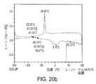
図20は、シリカ−PBD−PEG600およびシリカ−PBD−PEG2000ナノ複合材料についてのDSCグラフを示している。シリカ−PBD−PEG600ナノ複合材料が、PBDについて−80.44℃においてTgを有していた。これと比べて、シリカ−PBD−PEG2000ナノ粒子複合材料は、−81.24℃と−63.80℃において2つのTgを有していた。第1のTgは、PBDについてのものであり、これは、それ自身−77℃のTgを有する。第2のTgは、PEG2000についてのものである。PEG600についてのTgは、データにおいて観測することが困難であった。また、PEG2000ナノ粒子複合材料は、−38.49℃においてTcを有していたが、PEG600ナノ粒子複合材料は、Tcを全く示さなかった。PEG600についてのTmは、9.75℃であり、一方、PEG2000のTmは3.16℃であった。通常、より高い分子量のポリマーは、より高い融点を有するが、一方、当該データは反対のことを示していた。PEG2000のTmのみは、およそ60℃である。これは、おそらく、PEG2000がPBDと相互作用するためである。 FIG. 20 shows DSC graphs for silica-PBD-PEG600 and silica-PBD-PEG2000 nanocomposites. The silica-PBD-PEG600 nanocomposite had a Tg for PBD at −80.44 ° C. In comparison, the silica-PBD-PEG2000 nanoparticle composite had two Tg's at -81.24 ° C and -63.80 ° C. The first Tg is for PBD, which itself has a Tg of −77 ° C. The second Tg is for PEG2000. The Tg for PEG600 was difficult to observe in the data. Also, the PEG2000 nanoparticle composite had Tc at −38.49 ° C., but the PEG600 nanoparticle composite did not show any Tc. The Tm for PEG600 was 9.75 ° C, while the Tm for PEG2000 was 3.16 ° C. Usually higher molecular weight polymers have higher melting points, while the data showed the opposite. Only Tm of PEG2000 is about 60 ° C. This is probably because PEG2000 interacts with PBD.
図21は、上述したNOHMS複合材料を使用して製造されたLi/Sバッテリーのサイクル性能を示している。当該結果は、コントロールとして使用された硫黄カソードバッテリーと比較して、NOHMSバッテリーが、サイクルの関数である限定されたキャパシティー損失の観点から、実質的により高いサイクル性能を示す。 FIG. 21 shows the cycle performance of a Li / S battery manufactured using the NOHMS composite material described above. The results show that the NOHMS battery has substantially higher cycle performance in terms of limited capacity loss as a function of cycle compared to the sulfur cathode battery used as a control.
以下のように、図21において評価されたバッテリーについてのカソード材料複合材料は、表1において示されている。 The cathode material composite for the battery evaluated in FIG. 21 is shown in Table 1 as follows.

図21の内容における実施された実験において、硫黄含有量は、様々なタイプのバッテリーについて違っていた。これは、硫黄含有量は、100のラバーに対して(phr)12個に維持されるからである。これは、ラバーのみがPBDの重量を示す。PBDの%重量含有量が変わるにしたがって、硫黄の重量含有量は、各タイプのバッテリーについて違う。 In the experiments conducted in the context of FIG. 21, the sulfur content was different for different types of batteries. This is because the sulfur content is maintained at 12 (phr) for 100 rubber. This indicates that only rubber indicates the weight of PBD. As the% weight content of PBD changes, the weight content of sulfur is different for each type of battery.
実験の詳細
アミノ官能化されたシリカ粒子を合成するため、3mlのテトラエチルオルトシリケート(アルドリッチ)、60mlのメタノール(アルドリッチ)、2.5mlの水酸化アンモニウム(EMD)を混合し、30分間攪拌するためそのままにしておいた。その後、2.5mlの3−トリメトキシシリルプロピル−ジエチレントリアミン(シラン)(ゲレスト)、2.5グラムのポリエチレングリコールメチルエーテル(mPEG)(アルドリッチ)、および20mlのメタノールをもともとの混合物に加えた。さらに5分後、2mlの0.6MのNaOH溶液を加えた。当該混合物は、さらに12時間反応させるために放置した。
Experimental Details To synthesize amino-functionalized silica particles, mix 3 ml tetraethylorthosilicate (Aldrich), 60 ml methanol (Aldrich), 2.5 ml ammonium hydroxide (EMD) and stir for 30 minutes I left it there. Thereafter, 2.5 ml of 3-trimethoxysilylpropyl-diethylenetriamine (silane) (Gerest), 2.5 grams of polyethylene glycol methyl ether (mPEG) (Aldrich), and 20 ml of methanol were added to the original mixture. After another 5 minutes, 2 ml of 0.6 M NaOH solution was added. The mixture was left to react for an additional 12 hours.
ナノゼータサイザー装置(ナノ−ZSマルバーンコーポレーション)を使用して、シリカ粒子のサイズおよびゼータ電位を測定した。当該測定は、溶媒としてメタノール(Visc=0.5476、RI=1.326)、粒子としてシリカ(Abs=0.10、RI=1.500)を使用して実行した。当該粒子のアミノ官能性を測定するため、20mlのシリカ溶液を20mlのDI水と混合して、メタノールとアンモニア溶液とが蒸発するまで、70℃のオーブンに置いたままにした。当量点を得るためにpHメーターを使用して滴定を実行した。当該サンプルにおいて存在していた水酸化ナトリウムは、滴定概算において主要な部分を占めていた。TEM(FEIテクナイ12スピリットツイン)分析装置を使用して、当該溶液中におけるシリカ粒子のサイズおよび存在を示した。 The size and zeta potential of the silica particles were measured using a nanozeta sizer device (Nano-ZS Malvern Corporation). The measurement was performed using methanol (Visc = 0.5476, RI = 1.326) as a solvent and silica (Abs = 0.10, RI = 1.500) as particles. To measure the amino functionality of the particles, 20 ml of silica solution was mixed with 20 ml of DI water and left in an oven at 70 ° C. until the methanol and ammonia solution evaporated. Titration was performed using a pH meter to obtain an equivalence point. Sodium hydroxide present in the sample was a major part of the titration estimate. A TEM (FEI Technai 12 Spirit Twin) analyzer was used to show the size and presence of silica particles in the solution.
シリカに対するポリブタジエンリンクのため、最初、150℃でホットプレートを使用して、100mlのN,N−ジメチルホルムアミド(DMF)(アルドリッチ)を加熱および攪拌した。シリカ粒子を有する50mlのメタノール溶液をゆっくりとDMFに添加した。当該混合物を1時間攪拌し、メタノールとアンモニアを除去した。12.5グラムのジカルボキシル終端ポリブタジエン(PBD)(Mn=4200アルドリッチ)および50mlのテトラハイドロフラン(THF)(JTベイカー)を混合し、ポリマーが完全に溶解するまで攪拌した。ポリマーの量は、シランに対するアミノ官能基と比較してモル換算でPBDのカルボキシル官能基の4倍を超えるように選択した。シリカDMFの溶液の体積は、当該溶液に、より多くのDMFを加えることにより50mlに設定した。PBD THF溶液およびシリカDMF溶液を、シリカDMF溶液をゆっくり加えることにより混合した。反応を24時間続くようにそのまま放置した。遠心分離器(アックスピン400フィッシャーサイエンティフィック)を使用して、シリカ−PBD粒子を分離した。上澄み液を含む浮遊PBDを廃棄し、沈殿物を回収した。付加的な遠心分離をTHFとDMFとの体積比率が4:3の溶液において実行した。PBDは、同等の量のTHFとDMFとが使用されたとき沈殿し始めるため当該比率が選択された。
For polybutadiene linking to silica, initially 100 ml of N, N-dimethylformamide (DMF) (Aldrich) was heated and stirred using a hot plate at 150 ° C. 50 ml methanol solution with silica particles was slowly added to DMF. The mixture was stirred for 1 hour to remove methanol and ammonia. 12.5 grams of dicarboxyl-terminated polybutadiene (PBD) (Mn = 4200 Aldrich) and 50 ml of tetrahydrofuran (THF) (JT Baker) were mixed and stirred until the polymer was completely dissolved. The amount of polymer was selected to be more than 4 times the carboxyl functional group of PBD in terms of mole compared to the amino functional group relative to silane. The volume of silica DMF solution was set to 50 ml by adding more DMF to the solution. PBD THF solution and silica DMF solution were mixed by slowly adding silica DMF solution. The reaction was left to continue for 24 hours. Silica-PBD particles were separated using a centrifuge (
当該シリカ−ポリブタジエン、PEGに対するポリエチレングリコール結合のため、PEGをPEGが2、カルボキシル基が3である比率となるように加えた。サンプルの2つの分離したバッチを作製し、2つの異なるモル重量を有するPEGをそれぞれに加えた。それらは、O−(2−アミノプロピル)−O’−(2−メトキシエチル)ポリプロピレングリコール(PEG600)(Mn=600 アルドリッチ)、およびポリエーテルアミン(PEG2000)(ジェフアミンM−2070、Mn=2000、ハンツマン)であった。当該混合物を24時間混合するために放置し、その後70℃で乾燥させた。 Due to the polyethylene glycol bond to the silica-polybutadiene and PEG, PEG was added so that the ratio of PEG was 2 and carboxyl group was 3. Two separate batches of samples were made and PEGs with two different molar weights were added to each. They include O- (2-aminopropyl) -O ′-(2-methoxyethyl) polypropylene glycol (PEG600) (Mn = 600 Aldrich), and polyetheramine (PEG2000) (Jeffamine M-2070, Mn = 2000). Huntsman). The mixture was left to mix for 24 hours and then dried at 70 ° C.
加硫処理は、150℃で実行した。アクセラレーターについて、2phrのテトラエチルチウラム二硫化物(アクロスオーガニックス)を使用した。アクティベーターについて、8phrの酸化亜鉛(アルドリッチコーポレーション)を使用した。また、3.2phrのステアリン酸(97%、フルカコーポレーション)および12phrの硫黄(試薬グレード、100メッシュ、アルドリッチコーポレーション)を使用した。NOHMS粒子について、当該複合材料におけるPBDの係数を、加硫処理のための反応剤の相対的な量を概算する際に使用した。これは、PBDのみが、硫黄と架橋するからである。 The vulcanization process was performed at 150 ° C. For the accelerator, 2 phr of tetraethylthiuram disulfide (Acros Organics) was used. For the activator, 8 phr zinc oxide (Aldrich Corporation) was used. 3.2 phr stearic acid (97%, Fluka Corporation) and 12 phr sulfur (reagent grade, 100 mesh, Aldrich Corporation) were also used. For NOHMS particles, the coefficient of PBD in the composite was used in estimating the relative amount of reactants for the vulcanization process. This is because only PBD crosslinks with sulfur.
コントロールとして使用されたラバー材料を削るため、液体窒素およびドライアイスを使用し当該ラバーを脆弱にしその後粉末にした。カーボンブラック(スーパーP−Li、ティムカルコーポレーション)を伝導性助剤として使用し、PVDF−HFP(キナー2801、アルケマインコーポレーション)をバインダーとして使用し、DMF(アルドリッチ)を溶媒として使用した。NOHMS材料、カーボンブラック、およびPVDF−HFPを60:20:20重量比率で混合した。当該スラリーを24時間混合するために放置し、その後、銅のディスク上に塗布した。これは、4時間、70℃のオーブン内で乾燥させ、12時間、真空下で120℃で乾燥させた。コントロールサンプルを製造した。当該コントロールサンプルには、(1)硫黄、(2)活性材料としての12phrの加硫処理PBDを含有する。活性材料としてNOHMSを含むセルは、また、12phrの硫黄を含有する。当該セルをアノードにおいてリチウム(0.75mm厚、99.9%、シグマアルドリッチ)により作製した。電解液は、1,3−ジオキソラン(アルドリッチ)とジメトキシエタン(アルドリッチ)との50:50重量比率混合物に溶解された、リチウムビス(トリフルオロメタン)スルホンイミド(アルドリッチ)の0.5M溶液であった。 To scrape the rubber material used as a control, liquid nitrogen and dry ice were used to make the rubber brittle and then powdered. Carbon black (Super P-Li, Timcal Corporation) was used as a conductive aid, PVDF-HFP (Kinner 2801, Alchemine Corporation) was used as a binder, and DMF (Aldrich) was used as a solvent. NOHMS material, carbon black, and PVDF-HFP were mixed in a 60:20:20 weight ratio. The slurry was left to mix for 24 hours and then applied onto a copper disk. This was dried in an oven at 70 ° C. for 4 hours and dried at 120 ° C. under vacuum for 12 hours. A control sample was produced. The control sample contains (1) sulfur and (2) 12 phr of vulcanized PBD as an active material. A cell containing NOHMS as the active material also contains 12 phr sulfur. The cell was made of lithium (0.75 mm thickness, 99.9%, Sigma-Aldrich) at the anode. Electrolyte was dissolved in a 50:50 weight ratio mixture of 1,3-dioxolane (Aldrich) and dimethoxyethane (Aldrich) was a 0.5M solution of lithium bis (trifluoromethane) sulfonimide (Aldrich) .
出願公開、特許出願、本明細書に引用された特許を含む全ての文献は、許容できる程度で、かつ各文献が個々におよび明確に参照により組み込まれることが示され本明細書に全体として説明されている同じ程度で、全体として、引用することにより本明細書に組み込まれる。 All documents, including published applications, patent applications, and patents cited herein, are tolerable and are described herein in their entirety, with each document shown to be incorporated individually and specifically by reference. To the same extent as incorporated herein by reference in their entirety.
本発明を説明する記載(特に、これに続く特許請求の範囲の記載)において用語”a”、”an”、および”the”並びに同様のものを使用することは、本明細書において示され当該記載に明確に矛盾する場合を除いて、単一もしくは複数の両方をカバーすると解釈される。用語”含む(comprising)”、”有する(having)”および”含有する(containing)”は、特に示す場合を除いて、オープンエンドターム(すなわち、”以下に限定される訳ではないが以下のものを含む”ことを意味する)。用語”接続された”は、間に介在するものが存在するとしても、部分的にもしくは全体的に内部に含まれ、取り付けられ、もしくは一緒に組み合わされたと解釈される。 The use of the terms “a”, “an”, and “the” and the like in the description (particularly in the claims that follow) describing the present invention is shown and described herein. Except as otherwise clearly contradicting the description, it will be construed to cover both single and multiple. The terms “comprising”, “having” and “containing” unless otherwise indicated, are open-ended terms (ie, but not limited to: Means “includes”). The term “connected” is intended to be partially or wholly contained internally, attached, or combined together, even though there are intervening objects.
本明細書において数値範囲を記載することは、本明細書において特に示された場合を除いて、当該範囲に含まれるそれぞれの分離した値を個々に参照する簡単な方法としての役割を果たすことを意図しており、各分離した値は、本明細書に個々に記載されるかのごとく本明細書に組み込まれている。 Described herein as a numerical range is to serve as an easy way to individually reference each separate value within that range, except where specifically indicated herein. Each discrete value is contemplated and is incorporated herein as if individually set forth herein.
本明細書において記載された全ての方法は、本明細書において特に示された場合、もしくは本明細書の記載と明確に矛盾する場合を除いて、任意の適切な順序で実行される。本明細書において与えられた任意のおよび全ての実施例もしくは例示的な文言(具体的には”例えば〜など”)を使用することは、単に、本発明の実施の形態を良好に例示することを意図し、特に要求する場合を除いて、本発明の範囲に対して限定を課すことを意図するものではない。 All methods described herein are performed in any suitable order unless otherwise indicated herein or otherwise clearly contradicting the description herein. The use of any and all of the examples or exemplary language given herein (specifically, “eg, etc.”) merely exemplifies the embodiments of the present invention. It is not intended to impose a limitation on the scope of the invention, except as otherwise required.
本明細書における文言は、本発明の実行にとって必要不可欠なものとしてクレームされていない如何なる要素を示すものとして解釈されるべきではない。 No language in the specification should be construed as indicating any element not claimed as essential to the practice of the invention.
当該技術分野における当業者にとって、本発明の精神および技術的範囲から逸脱しない限り、当該実施の形態に対して様々な修正および変更を加えてもよいことは明らかである。開示された特定の一または複数の形式に本発明を限定する意図は存在しないけれども、反対に、添付の特許請求の範囲に規定された本発明の精神および技術的範囲に属する全ての修正、代替の構造等をカバーすることを意図する。そのため、本発明は、本発明の修正および変更が添付の特許請求の範囲等に含まれる場合、これらをカバーすることを意図する。 It will be apparent to those skilled in the art that various modifications and variations can be made to the embodiments without departing from the spirit and scope of the invention. There is no intention to limit the invention to the particular form or forms disclosed, but on the contrary, all modifications and alternatives falling within the spirit and scope of the invention as defined by the appended claims It is intended to cover the structure etc. Therefore, the present invention intends to cover modifications and changes of the present invention when they are included in the appended claims.
それゆえ、当該実施の形態は、本発明を限定するのではなく、本発明を例示するものである。本発明に係る、さらに、添付の請求項に係る、ナノポーラス材料、ナノ粒子、並びにナノポーラス材料もしくはナノ粒子を作製する方法を提供するが、本実施の形態に係る、ナノポーラス材料、ナノ粒子、ナノポーラス材料もしくはナノ粒子を製造するための方法に関し、方法、材料、構造および寸法に対して修正および変更を加えてもよい。
本明細書の開示内容は、以下の態様を含む。
態様1:
カーボン材料支持体と、
上記カーボン材料支持体に支持された硫黄材料と、を備えるナノ粒子であって、
カソード内に当該ナノ粒子を含むリチウム−硫黄セルのサイクリックボルタモグラムが、約2.4ボルトの位置に安定な還元ピークを示すことを特徴とするナノ粒子。
態様2:
上記サイクリックボルタモグラムが、テトラグリム電解液に溶解されたリチウムビス(トリフルオロメタンスルホン)イミドを使用し、
当該サイクリックボルタモグラムが、約2.0ボルトの位置に安定な還元ピークを示し、
当該サイクリックボルタモグラムが、約2.35ボルトの位置に安定な酸化ピークを示し、約2.45ボルトの位置に安定な酸化ピークを示す態様1記載のナノ粒子。
態様3:
上記カーボン材料支持体が中空状球状体を含む態様1記載のナノ粒子。
態様4:
上記カーボン材料支持体が少なくとも部分的にグラファイトカーボン材料を含む態様1記載のナノ粒子。
態様5:
上記硫黄材料が、約70質量パーセント以下の硫黄材料を含有するアモルファス硫黄材料を含む態様1記載のナノ粒子。
態様6:
導電性支持体と、
上記導電性支持体の上に配置されたコーティングと、を備え、
当該コーティングは、
カーボン材料支持体と、
上記カーボン材料支持体に支持された硫黄材料と、を備えるナノ粒子であって、
カソード内に当該ナノ粒子を含むリチウム−硫黄セルのサイクリックボルタモグラムが、約2.4ボルトの位置に安定な還元ピークを示すナノ粒子を備える電極。
態様7:
導電性支持体と、
上記導電性支持体の上に配置されたコーティングと、を備え、
当該コーティングは、
カーボン材料支持体と、
上記カーボン材料支持体に支持された硫黄材料と、を備えるナノ粒子であって、
カソード内に当該ナノ粒子を含むリチウム−硫黄セルのサイクリックボルタモグラムが、約2.4ボルトの位置に安定な還元ピークを示すナノ粒子を備える電極を具有するバッテリー。
態様8:
上記電極がカソードを含み、
上記バッテリーがリチウムイオンバッテリーを含む態様7記載のバッテリー。
態様9:
バルクのカーボン材料支持体と、
上記バルクのカーボン材料支持体の上に支持された硫黄材料と、を備え、
カソード内に当該ナノポーラス材料から生成されたナノ粒子を含むリチウム−硫黄セルのサイクリックボルタモグラムが、約2.4ボルトの位置に安定な還元ピークを示すナノポーラス材料。
態様10:
上記サイクリックボルタモグラムが、テトラグリム電解液に溶解されたリチウムビス(トリフルオロメタンスルホン)イミドを使用し、
上記サイクリックボルタモグラムが、約2.0ボルトの位置に安定な還元ピークを示し、
上記サイクリックボルタモグラムが、約2.35ボルトの位置に安定な酸化ピークを示し、約2.45ボルトの位置に安定な酸化ピークを示す態様9記載のナノポーラス材料。
態様11:
少なくとも約450℃の温度、少なくとも約2気圧の圧力において、硫黄材料ソースでポーラスカーボン材料支持体を処理し、硫黄注入ポーラスカーボン材料支持体を提供する工程を含む、ナノポーラス材料の製造方法。
態様12:
上記のポーラスカーボン材料支持体を処理する工程が、硫黄材料ソースおよび不活性ガスを用いる態様11記載の製造方法。
態様13:
上記ポーラスカーボン材料支持体が、約0.5〜約20ナノメートルの平均粒子サイズを有する態様11記載の製造方法。
態様14:
上記ポーラスカーボン材料支持体が、中空状ポーラスカーボンナノ粒子を含む態様11記載の製造方法。
態様15:
上記ポーラスカーボン材料支持体が、中空状ではないナノ粒子を含む態様11記載の製造方法。
態様16:
上記ポーラスカーボン材料支持体が、石炭から構成されている態様11記載の製造方法。
態様17:
上記ポーラスカーボン材料支持体が、カーボンエアロゲルから構成されている態様11記載の製造方法。
態様18:
上記ポーラスカーボン材料支持体が、石炭、カーボンエアロゲル、ポリアクリロニトリル、多糖、クエン酸、没食子酸、桂皮酸、ポリスチレン、および、ポリメチルメタクリレートカーボンソース材料からなる群から選択されたカーボンソース材料から構成されている態様11記載の製造方法。
態様19:
カーボン材料層をテンプレートナノ粒子上に形成し、カーボン材料コートテンプレートナノ粒子を準備する工程と、
上記カーボン材料コートテンプレートナノ粒子から上記テンプレートナノ粒子を溶解し、中空状のカーボン材料ナノ粒子を作製する工程と、
少なくとも約450℃の温度、少なくとも約2気圧の圧力において、硫黄材料ソースを中空状カーボン材料ナノ粒子に注入し、硫黄注入中空状カーボン材料ナノ粒子を作製する工程と、を備える、ナノ粒子の製造方法。
態様20:
上記のカーボン材料層を形成する工程が、溶液コーティングおよび熱分解方法を使用する態様19記載の製造方法。
態様21:
上記の中空状カーボン材料ナノ粒子に注入する工程が、約2〜約20気圧の圧力における硫黄注入を用いる態様19記載の製造方法。
態様22:
上記の注入工程が、硫黄材料ソースおよび不活性ガスを用いる態様19記載の製造方法。
態様23:
少なくとも約450℃の温度、少なくとも約2気圧の圧力において、硫黄材料ソースでバルクのポーラスカーボン材料支持体を処理し、硫黄注入バルクポーラスカーボン材料支持体を準備する工程と、
上記の硫黄注入バルクポーラスカーボン材料支持体を粉砕し、上記ナノ粒子を作製する工程と、を備えるナノ粒子の製造方法。
態様24:
金属酸化物材料を含有するコアと、
上記コア上に配置され、イオン伝導性ポリマー材料に接合された硫黄架橋ポリマルチエンポリマー材料を含むシェルと、を備えるナノ粒子。
態様25:
上記ナノ粒子は、
約2〜約20質量%の金属酸化物材料と、
約10〜約40質量%のポリマルチエンポリマー材料と、
約2〜約5質量%のイオン伝導性ポリマー材料と、
約2〜約80質量%の硫黄と、を含む態様24記載のナノ粒子。
態様26:
上記コアが、シリコン酸化物材料を含み、
上記ポリマルチエンポリマー材料が、ポリブタジエンポリマー材料を含み、
上記イオン伝導性ポリマー材料が、ポリエチレングリコールポリマー材料を含む態様24記載のナノ粒子。
態様27:
上記シェル層が、上記コアに接合され、
上記シェル層が、上記イオン伝導性ポリマー材料に接続された硫黄架橋ポリマルチエンポリマー材料を含有するジブロックコポリマーを含む態様24記載のナノ粒子。
態様28:
導電性支持体と、
上記導電性支持体上に配置されたコーティングと、を有し、
当該コーティングは、
金属酸化物材料を含むコアと、
上記コア上に配置されたシェル層であって、イオン伝導性ポリマー材料に接合された硫黄架橋ポリマルチエンポリマー材料を含有するシェル層と、を備えるナノ粒子を含む電極。
態様29:
導電性支持体と、
上記導電性支持体上に配置されたコーティングと、を有し、
当該コーティングは、
金属酸化物材料を含むコアと、
上記コア上に配置されたシェル層であって、イオン伝導性ポリマー材料に接合された硫黄架橋ポリマルチエンポリマー材料を含有するシェル層と、を備えるナノ粒子を含むバッテリー。
態様30:
上記電極がカソードを含み、
上記バッテリーがリチウムイオンバッテリーを含む態様29記載のバッテリー。
態様31:
有機官能性金属酸化物コアを作製する工程と、
上記有機官能性金属酸化物コアを多官能性ポリマルチエンポリマー材料および多官能性イオン伝導性ポリマー材料の一方と反応させて部分シース金属酸化物コアを作製する工程と、
上記部分シース金属酸化物コアを官能性ポリマルチエンポリマー材料および官能性イオン伝導性ポリマー材料と反応させ、上記有機官能性金属酸化物コアに接合されたポリマルチエンポリマー材料とイオン伝導性ポリマー材料シェルを作製する工程と、
硫黄材料を用いて上記ポリマルチエンポリマー材料を加硫処理する工程と、を備える、ナノ粒子の製造方法。
態様32:
上記の有機官能性金属酸化物コアを反応させる工程および上記の部分シース金属酸化物コアを反応させる工程により、ジブロックコポリマー材料が形成される態様31記載の方法。
態様33:
上記ジブロックコポリマー材料が、上記有機官能性金属酸化物コアに接合されたポリマルチエンポリマー材料を含有する態様32記載の方法。
態様34:
上記ジブロックコポリマー材料が、上記有機官能性金属酸化物コアに接合されたイオン伝導性ポリマー材料を含有する態様32記載の方法。
Therefore, this embodiment does not limit the present invention but exemplifies the present invention. According to the present invention, there is further provided a nanoporous material, a nanoparticle, and a method for producing a nanoporous material or a nanoparticle according to the appended claims. However, the nanoporous material, the nanoparticle, and the nanoporous material according to the present embodiment are provided. Alternatively, modifications and changes may be made to methods, materials, structures, and dimensions with respect to methods for producing nanoparticles.
The disclosure of the present specification includes the following aspects.
Aspect 1:
A carbon material support;
A sulfur material supported by the carbon material support, and a nanoparticle comprising:
A nanoparticle, wherein a cyclic voltammogram of a lithium-sulfur cell containing the nanoparticle in the cathode shows a stable reduction peak at a position of about 2.4 volts.
Aspect 2:
The cyclic voltammogram uses lithium bis (trifluoromethanesulfone) imide dissolved in a tetraglyme electrolyte,
The cyclic voltammogram shows a stable reduction peak at a position of about 2.0 volts,
The nanoparticle according to
Aspect 3:
The nanoparticle according to
Aspect 4:
The nanoparticle according to
Aspect 5:
The nanoparticle of
Aspect 6:
A conductive support;
A coating disposed on the conductive support,
The coating is
A carbon material support;
A sulfur material supported by the carbon material support, and a nanoparticle comprising:
An electrode comprising nanoparticles in which a cyclic voltammogram of a lithium-sulfur cell containing the nanoparticles in the cathode shows a stable reduction peak at a position of about 2.4 volts.
Aspect 7:
A conductive support;
A coating disposed on the conductive support,
The coating is
A carbon material support;
A sulfur material supported by the carbon material support, and a nanoparticle comprising:
A battery comprising an electrode comprising nanoparticles in which a cyclic voltammogram of a lithium-sulfur cell containing the nanoparticles in the cathode shows a stable reduction peak at a position of about 2.4 volts.
Aspect 8:
The electrode includes a cathode;
The battery according to aspect 7, wherein the battery includes a lithium ion battery.
Aspect 9:
A bulk carbon material support;
A sulfur material supported on the bulk carbon material support,
A nanoporous material in which a cyclic voltammogram of a lithium-sulfur cell containing nanoparticles produced from the nanoporous material in the cathode shows a stable reduction peak at a position of about 2.4 volts.
Aspect 10:
The cyclic voltammogram uses lithium bis (trifluoromethanesulfone) imide dissolved in a tetraglyme electrolyte,
The cyclic voltammogram shows a stable reduction peak at a position of about 2.0 volts,
The nanoporous material according to
Aspect 11:
A method of producing a nanoporous material comprising treating a porous carbon material support with a sulfur material source at a temperature of at least about 450 ° C. and a pressure of at least about 2 atmospheres to provide a sulfur-implanted porous carbon material support.
Aspect 12:
The manufacturing method according to aspect 11, wherein the step of treating the porous carbon material support uses a sulfur material source and an inert gas.
Aspect 13:
The method according to embodiment 11, wherein the porous carbon material support has an average particle size of about 0.5 to about 20 nanometers.
Aspect 14:
The manufacturing method of the aspect 11 with which the said porous carbon material support body contains hollow porous carbon nanoparticle.
Aspect 15:
The manufacturing method of the aspect 11 with which the said porous carbon material support body contains the nanoparticle which is not hollow.
Aspect 16:
The manufacturing method of the aspect 11 with which the said porous carbon material support body is comprised from coal.
Aspect 17:
The manufacturing method of the aspect 11 with which the said porous carbon material support body is comprised from the carbon aerogel.
Aspect 18:
The porous carbon material support is composed of a carbon source material selected from the group consisting of coal, carbon aerogel, polyacrylonitrile, polysaccharide, citric acid, gallic acid, cinnamic acid, polystyrene, and polymethyl methacrylate carbon source material. The manufacturing method of the aspect 11 which has.
Aspect 19:
Forming a carbon material layer on the template nanoparticles and preparing carbon material coated template nanoparticles;
Dissolving the template nanoparticles from the carbon material-coated template nanoparticles to produce hollow carbon material nanoparticles;
Injecting a sulfur material source into the hollow carbon material nanoparticles at a temperature of at least about 450 ° C. and a pressure of at least about 2 atmospheres to produce the sulfur-injected hollow carbon material nanoparticles. Method.
Aspect 20:
The manufacturing method according to aspect 19, wherein the step of forming the carbon material layer uses a solution coating and a thermal decomposition method.
Aspect 21:
The manufacturing method according to aspect 19, wherein the step of injecting into the hollow carbon material nanoparticles uses sulfur injection at a pressure of about 2 to about 20 atmospheres.
Aspect 22:
The manufacturing method according to aspect 19, wherein the implantation step uses a sulfur material source and an inert gas.
Aspect 23:
Treating a bulk porous carbon material support with a sulfur material source at a temperature of at least about 450 ° C. and a pressure of at least about 2 atmospheres to provide a sulfur-implanted bulk porous carbon material support;
Crushing the above sulfur-implanted bulk porous carbon material support to produce the nanoparticles, and a method for producing nanoparticles.
Aspect 24:
A core containing a metal oxide material;
A shell comprising a sulfur-crosslinked polymultiene polymer material disposed on the core and bonded to an ion conductive polymer material.
Aspect 25:
The nanoparticles are
About 2 to about 20% by weight of a metal oxide material;
From about 10 to about 40% by weight of a polymultiene polymer material;
About 2 to about 5% by weight of the ion conductive polymer material;
25. The nanoparticle of
Aspect 26:
The core includes a silicon oxide material;
The polymultiene polymer material comprises a polybutadiene polymer material;
25. The nanoparticle of
Aspect 27:
The shell layer is bonded to the core;
25. The nanoparticle of
Aspect 28:
A conductive support;
A coating disposed on the conductive support,
The coating is
A core comprising a metal oxide material;
An electrode comprising nanoparticles comprising a shell layer disposed on the core, the shell layer comprising a sulfur-crosslinked polymultiene polymer material joined to an ion conductive polymer material.
Aspect 29:
A conductive support;
A coating disposed on the conductive support,
The coating is
A core comprising a metal oxide material;
A battery comprising nanoparticles comprising a shell layer disposed on the core, the shell layer comprising a sulfur-crosslinked polymultiene polymer material joined to an ion conductive polymer material.
Aspect 30:
The electrode includes a cathode;
The battery according to aspect 29, wherein the battery includes a lithium ion battery.
Aspect 31:
Producing an organofunctional metal oxide core;
Reacting the organofunctional metal oxide core with one of a polyfunctional polymultiene polymer material and a polyfunctional ion conductive polymer material to produce a partially sheathed metal oxide core;
The partially sheathed metal oxide core is reacted with a functional polymultiene polymer material and a functional ion conductive polymer material to form a polymultiene polymer material and an ion conductive polymer material shell bonded to the organofunctional metal oxide core. Manufacturing process;
And a step of vulcanizing the polymultiene polymer material using a sulfur material.
Aspect 32:
The method of embodiment 31, wherein the diblock copolymer material is formed by reacting the organofunctional metal oxide core and reacting the partially sheathed metal oxide core.
Aspect 33:
The method of embodiment 32, wherein the diblock copolymer material comprises a polymultiene polymer material joined to the organofunctional metal oxide core.
Aspect 34:
36. The method of embodiment 32, wherein the diblock copolymer material comprises an ion conducting polymer material joined to the organofunctional metal oxide core .
Claims (22)
上記中空状球状体メソポーラスカーボン材料上および内部に支持された元素硫黄材料と
を含むナノ粒子であって、
カソード内に当該ナノ粒子を含むリチウム−硫黄セルのサイクリックボルタモグラムが、複数のサイクリックボルタモグラムのサイクルに亘って、2.4ボルトの位置に還元ピークを示すナノ粒子。 A carbon material support comprising a hollow spherical mesoporous carbon material;
Nanoparticles containing elemental sulfur material supported on and inside the hollow spherical mesoporous carbon material ,
1. a cyclic voltammogram of a lithium-sulfur cell containing the nanoparticles in the cathode , over a cycle of multiple cyclic voltammograms ; Nanoparticles showing the original peak instead of the location of 4 volts.
上記サイクリックボルタモグラムが、テトラグリム電解液に溶解されたリチウムビス(トリフルオロメタンスルホン)イミドを使用し、
当該サイクリックボルタモグラムが、少なくとも10回のサイクリックボルタモグラムのサイクルに亘って、2.0ボルトの位置に還元ピークを示し、
当該サイクリックボルタモグラムが、少なくとも10回のサイクリックボルタモグラムのサイクルに亘って、2.35ボルトの位置に酸化ピークを示し、2.45ボルトの位置に酸化ピークを示す請求項1記載のナノ粒子。 The cyclic voltammogram is, over at least 10 times of the cyclic voltammograms of cycle 2. 4 instead of the bolt position shows the original peak,
The cyclic voltammogram uses lithium bis (trifluoromethanesulfone) imide dissolved in a tetraglyme electrolyte,
1. the cyclic voltammogram is at least 10 cyclic voltammogram cycles ; 0 instead of the bolt position shows the original peak,
1. the cyclic voltammogram is at least 10 cyclic voltammogram cycles ; It shows the oxidation peak 35 volt position, 2. Nanoparticles according to claim 1, wherein an acid of peaks 45 volt position.
上記導電性支持体の上に配置されたコーティングであって、
中空状球状体メソポーラスカーボン材料を含むカーボン材料支持体と、
上記中空状球状体メソポーラスカーボン材料上および内部に支持された元素硫黄材料と、を含むナノ粒子であって、カソード内に当該ナノ粒子を含むリチウム−硫黄セルのサイクリックボルタモグラムが、複数のサイクリックボルタモグラムのサイクルに亘って、2.4ボルトの位置に還元ピークを示すナノ粒子
を含むコーティングと
を含む電極。 A conductive support;
A coating disposed on the conductive support,
A carbon material support comprising a hollow spherical mesoporous carbon material;
A nanoparticle comprising the a hollow spherical body mesoporous carbon materials on and supported elemental sulfur material therein, a lithium containing the nanoparticles in the cathode - cyclic voltammogram of sulfur cell, a plurality of cyclic Throughout the voltammogram cycle, 2 . Electrode comprising a coating comprising nanoparticles indicating the original peak instead of the location of 4 volts.
上記導電性支持体の上に配置されたコーティングであって、
中空状球状体メソポーラスカーボン材料を含むカーボン材料支持体と、
上記中空状球状体メソポーラスカーボン材料上および内部に支持された元素硫黄材料と、を含むナノ粒子であって、カソード内に当該ナノ粒子を含むリチウム−硫黄セルのサイクリックボルタモグラムが、複数のサイクリックボルタモグラムのサイクルに亘って、2.4ボルトの位置に還元ピークを示すナノ粒子
を含むコーティングと
を含む電極を具有するバッテリー。 A conductive support;
A coating disposed on the conductive support,
A carbon material support comprising a hollow spherical mesoporous carbon material;
A nanoparticle comprising the a hollow spherical body mesoporous carbon materials on and supported elemental sulfur material therein, a lithium containing the nanoparticles in the cathode - cyclic voltammogram of sulfur cell, a plurality of cyclic Throughout the voltammogram cycle, 2 . Battery for androgynous an electrode containing a coating comprising nanoparticles indicating the original peak instead of the location of 4 volts.
上記バッテリーがリチウムイオンバッテリーを含む請求項6記載のバッテリー。 The electrode includes a cathode;
The battery according to claim 6, wherein the battery comprises a lithium ion battery.
上記バルクのカーボン材料支持体の上および内部に支持された元素硫黄材料と
を含むナノポーラス材料であって、
カソード内に当該ナノポーラス材料から生成されたナノ粒子を含むリチウム−硫黄セルのサイクリックボルタモグラムが、複数のサイクリックボルタモグラムのサイクルに亘って、2.4ボルトの位置に還元ピークを示すナノポーラス材料。 A bulk mesoporous carbon material support;
A nanoporous material comprising elemental sulfur material supported on and within the bulk carbon material support,
1. a cyclic voltammogram of a lithium-sulfur cell containing nanoparticles produced from the nanoporous material in the cathode over a plurality of cyclic voltammogram cycles ; Nanoporous material exhibiting the original peak instead of the location of 4 volts.
上記サイクリックボルタモグラムが、テトラグリム電解液に溶解されたリチウムビス(トリフルオロメタンスルホン)イミドを使用し、
上記サイクリックボルタモグラムが、少なくとも10回のサイクリックボルタモグラムのサイクルに亘って、2.0ボルトの位置に還元ピークを示し、
上記サイクリックボルタモグラムが、少なくとも10回のサイクリックボルタモグラムのサイクルに亘って、2.35ボルトの位置に酸化ピークを示し、2.45ボルトの位置に酸化ピークを示す請求項8記載のナノポーラス材料。 The cyclic voltammogram is, over at least 10 times of the cyclic voltammograms of cycle 2. 4 instead of the bolt position shows the original peak,
The cyclic voltammogram uses lithium bis (trifluoromethanesulfone) imide dissolved in a tetraglyme electrolyte,
1. The cyclic voltammogram is subjected to at least 10 cyclic voltammogram cycles ; 0 instead of the bolt position shows the original peak,
1. The cyclic voltammogram is subjected to at least 10 cyclic voltammogram cycles ; It shows the oxidation peak 35 volt position, 2. Nanoporous material according to claim 8, wherein an acid of peaks 45 volt position.
上記カーボン材料コートテンプレートナノ粒子から上記テンプレートナノ粒子を溶解し、中空状のカーボン材料ナノ粒子を作製する工程と、
少なくとも450℃の温度、少なくとも2気圧の圧力において、硫黄材料ソースを中空状カーボン材料ナノ粒子に注入し、硫黄注入中空状カーボン材料ナノ粒子を作製する工程と、を備える、ナノ粒子の製造方法。 Forming a carbon material layer on the template nanoparticles and preparing carbon material coated template nanoparticles;
Dissolving the template nanoparticles from the carbon material-coated template nanoparticles to produce hollow carbon material nanoparticles;
Least the temperature of even 4 50 ° C., at a pressure of least than two atmospheres, comprising injecting a sulfur material source to the hollow carbon material nanoparticles, a process of forming a sulfur injection hollow carbon material nanoparticles, the nano Particle manufacturing method.
上記の硫黄注入バルクメソポーラスカーボン材料支持体を粉砕し、ナノ粒子を作製する工程と、を備えるナノ粒子の製造方法。 Least the temperature of even 4 50 ° C., at a pressure of least than two atmospheres, to process the mesoporous carbon material support of the bulk sulfur material source, a step of preparing a sulfur injection bulk mesoporous carbon material support,
Pulverizing the above sulfur injection bulk mesoporous carbon material support, method for producing a nanoparticle comprising a step of preparing a nano-particles.
Applications Claiming Priority (3)
| Application Number | Priority Date | Filing Date | Title |
|---|---|---|---|
| US41164510P | 2010-11-09 | 2010-11-09 | |
| US61/411,645 | 2010-11-09 | ||
| PCT/US2011/059722 WO2012064702A2 (en) | 2010-11-09 | 2011-11-08 | Sulfur containing nanoporous materials, nanoparticles, methods and applications |
Publications (3)
| Publication Number | Publication Date |
|---|---|
| JP2014502405A JP2014502405A (en) | 2014-01-30 |
| JP2014502405A5 JP2014502405A5 (en) | 2014-12-25 |
| JP6302249B2 true JP6302249B2 (en) | 2018-03-28 |
Family
ID=46051504
Family Applications (1)
| Application Number | Title | Priority Date | Filing Date |
|---|---|---|---|
| JP2013538819A Expired - Fee Related JP6302249B2 (en) | 2010-11-09 | 2011-11-08 | Sulfur-containing nanoporous materials, nanoparticles, methods and applications |
Country Status (6)
| Country | Link |
|---|---|
| US (2) | US9882199B2 (en) |
| EP (1) | EP2638584B1 (en) |
| JP (1) | JP6302249B2 (en) |
| KR (1) | KR102123918B1 (en) |
| CN (1) | CN103339770B (en) |
| WO (1) | WO2012064702A2 (en) |
Families Citing this family (51)
| Publication number | Priority date | Publication date | Assignee | Title |
|---|---|---|---|---|
| WO2012109648A1 (en) * | 2011-02-11 | 2012-08-16 | The Penn State Research Foundation | Carbon-metal oxide-sulfur cathodes for high-performance lithium-sulfur batteries |
| KR101384198B1 (en) * | 2011-05-31 | 2014-04-25 | 한양대학교 산학협력단 | Manufacturing method of carbon sulfur complex, carbon sulfur complex made by the same, lithium sulfur battery including the same |
| CN103875097A (en) | 2011-09-12 | 2014-06-18 | 小利兰斯坦福大学理事会 | Encapsulated sulfur cathodes for rechargeable lithium batteries |
| US11052375B2 (en) * | 2012-04-26 | 2021-07-06 | Lawrence Livermore National Security, Llc | Adsorption cooling system using carbon aerogel |
| DE102012109720A1 (en) * | 2012-10-11 | 2014-04-30 | Heraeus Quarzglas Gmbh & Co. Kg | Composite of porous carbon and sulfur-containing active material and process for its preparation |
| CN105283983B (en) * | 2012-11-19 | 2018-08-31 | 苏里亚·S·莫甘缇 | Carbon is perfused in sulphur for secondary battery material |
| CN105190966B (en) * | 2012-12-19 | 2018-06-12 | 锡安能量公司 | electrode structure and its manufacturing method |
| US9306207B2 (en) * | 2012-12-28 | 2016-04-05 | Hyundai Motor Company | Method of fabricating sulfur-infiltrated mesoporous conductive nanocomposites for cathode of lithium-sulfur secondary battery |
| US8980471B2 (en) * | 2013-02-21 | 2015-03-17 | Toyota Motor Engineering & Manufacturing North America, Inc. | Carbon-sulfur composites encapsulated with polyelectrolyte multilayer membranes |
| WO2014169195A1 (en) * | 2013-04-12 | 2014-10-16 | Cornell University | Carbon-sulfur based core-shell materials compositions, methods and applications |
| CN103208618B (en) * | 2013-04-24 | 2015-10-28 | 中国科学院苏州纳米技术与纳米仿生研究所 | Carbon in lithium ion battery sulphur composite positive pole and preparation method thereof |
| US20160111721A1 (en) * | 2013-05-07 | 2016-04-21 | The Regents Of The University Of California | Voltage-responsive coating for lithium-sulfur battery |
| US20160372742A1 (en) * | 2013-07-05 | 2016-12-22 | Cornell Uniiversity | Yoke-shell nanoparticle, method and applications |
| CN105594022B (en) | 2013-09-30 | 2019-02-01 | 罗伯特·博世有限公司 | For lithium-sulfur cell containing sulfur compound, prepare the method for the compound and electrode material and lithium-sulfur cell comprising the compound |
| KR101783568B1 (en) * | 2013-10-07 | 2017-09-29 | 닛산 지도우샤 가부시키가이샤 | Electrode material for non-aqueous electrolyte secondary battery, and non-aqueous electrolyte secondary battery electrode and non-aqueous electrolyte secondary battery using same |
| KR101783567B1 (en) * | 2013-10-07 | 2017-09-29 | 닛산 지도우샤 가부시키가이샤 | Electrode material for non-aqueous electrolyte secondary battery, and non-aqueous electrolyte secondary battery electrode and non-aqueous electrolyte secondary battery using same |
| WO2015058057A1 (en) * | 2013-10-18 | 2015-04-23 | Nohms Technologies, Inc | Functionalized carbons for lithium-sulfur batteries |
| WO2015119887A1 (en) * | 2014-02-04 | 2015-08-13 | Nivo Systems, Inc. | Open framework composites, methods for producing and using such composites |
| US9437871B2 (en) | 2014-02-05 | 2016-09-06 | GM Global Technology Operations LLC | Sulfur based active material for a positive electrode |
| US9302914B2 (en) | 2014-02-28 | 2016-04-05 | GM Global Technology Operations LLC | Methods for making hollow carbon materials and active materials for electrodes |
| WO2015165762A1 (en) * | 2014-04-30 | 2015-11-05 | Basf Se | Process for producing a monolithic body of a porous carbon material, monolithic bodies of special porous carbon materials and their use |
| EP3152793A1 (en) | 2014-06-06 | 2017-04-12 | Robert Bosch GmbH | Cathode material for lithium sulphur cells |
| US9819015B2 (en) | 2014-09-18 | 2017-11-14 | Toyota Motor Engineering & Manufacturing North America, Inc. | Encapsulated sulfur sub-micron particles as electrode active material |
| US10050265B2 (en) | 2014-12-18 | 2018-08-14 | Samsung Electronics Co., Ltd. | Positive electrode having sulfur contained in pores between nanocarbon structures, alkali metal-sulfur battery including the same, and method of preparing the positive electrode |
| KR101704186B1 (en) | 2015-04-16 | 2017-02-07 | 현대자동차주식회사 | A cathode for all-solid-state lithium sulfur battery |
| CN104916828B (en) * | 2015-04-16 | 2017-06-16 | 中国人民解放军国防科学技术大学 | Three-dimensional grapheme hollow carbon sphere/sulphur composite and preparation method thereof and the application in lithium-sulfur cell |
| CN104817066A (en) * | 2015-05-18 | 2015-08-05 | 新疆大学 | Method for preparing pitch-based hollow carbon spheres |
| US10186730B2 (en) | 2015-07-15 | 2019-01-22 | Samsung Electronics Co., Ltd. | Electrolyte solution for secondary battery and secondary battery |
| KR101990615B1 (en) | 2015-09-23 | 2019-06-18 | 주식회사 엘지화학 | Positive Active Material and Positive Electrode Comprising Metal Nanoparticles and Lithium-Sulfur Battery Comprising Thereof |
| WO2017052246A1 (en) * | 2015-09-23 | 2017-03-30 | 주식회사 엘지화학 | Cathode active material and cathode comprising metal nano particles, and lithium-sulfur battery comprising same |
| US9985284B2 (en) * | 2015-11-18 | 2018-05-29 | GM Global Technology Operations LLC | Forming sulfur-based positive electrode active materials |
| CN106898491B (en) * | 2015-12-18 | 2018-12-25 | 中国科学院大连化学物理研究所 | A kind of electrode of super capacitor and its preparation |
| CN105742593A (en) * | 2016-02-29 | 2016-07-06 | 哈尔滨工业大学 | Cathode material for lithium-sulfur battery and preparation method of cathode material |
| JP6745504B2 (en) * | 2016-04-05 | 2020-08-26 | 住友ゴム工業株式会社 | Positive electrode active material for lithium-ion secondary battery, positive electrode and lithium-ion secondary battery |
| KR102003304B1 (en) * | 2016-08-10 | 2019-07-24 | 주식회사 엘지화학 | Cathode Active Materials Comprising Polyimide, Manufacturing Method Thereof and Lithium-Sulfur Battery Comprising The Same |
| US10424784B2 (en) | 2016-10-28 | 2019-09-24 | GM Global Technology Operations LLC | Negative electrode including silicon nanoparticles having a carbon coating thereon |
| JP6500173B2 (en) * | 2016-11-25 | 2019-04-17 | 富士シリシア化学株式会社 | Positive electrode active material, positive electrode, and secondary battery |
| CN109528755A (en) | 2017-08-10 | 2019-03-29 | 苏州魁星新材料科技有限公司 | One kind composition containing nano-sulfur and its application |
| US10637048B2 (en) | 2018-05-30 | 2020-04-28 | GM Global Technology Operations LLC | Silicon anode materials |
| WO2020032454A1 (en) * | 2018-08-08 | 2020-02-13 | 주식회사 엘지화학 | Sulfur-carbon composite, preparation method therefor, and positive electrode and lithium secondary battery comprising same |
| CN109301246B (en) * | 2018-09-28 | 2021-07-02 | 东北大学秦皇岛分校 | Sulfur-doped hard carbon material, preparation method thereof and potassium ion battery using sulfur-doped hard carbon material as negative electrode |
| JP7196304B2 (en) * | 2018-11-22 | 2022-12-26 | エルジー エナジー ソリューション リミテッド | Lithium-sulfur secondary battery |
| WO2020149659A1 (en) | 2019-01-16 | 2020-07-23 | 주식회사 엘지화학 | Lithium secondary battery |
| CN111755688A (en) * | 2019-03-29 | 2020-10-09 | 住友橡胶工业株式会社 | Sulfur-based active material |
| CN110380052B (en) * | 2019-07-19 | 2022-05-17 | 东营昆宇电源科技有限公司 | High-conductivity sulfur-based composite material for lithium-sulfur battery positive electrode |
| US11374218B2 (en) | 2019-08-21 | 2022-06-28 | GM Global Technology Operations LLC | Multilayer siloxane coatings for silicon negative electrode materials for lithium ion batteries |
| US11843110B2 (en) | 2019-10-30 | 2023-12-12 | GM Global Technology Operations LLC | Methods for controlling formation of multilayer carbon coatings on silicon-containing electroactive materials for lithium-ion batteries |
| CN111293371B (en) * | 2020-01-14 | 2022-09-27 | 电子科技大学 | Method for inhibiting lithium side reaction and dendritic crystal growth of electrolyte reservoir |
| US20230220269A1 (en) * | 2020-06-02 | 2023-07-13 | Nissan Chemical America Corporation | Using silica nanoparticles to reduce the deposition of solid sulfur in natural gas wells |
| WO2021247578A1 (en) * | 2020-06-02 | 2021-12-09 | Nissan Chemical America Corporation | Method of introducing nonpolar natural nanoparticles to reduce the deposition of solid sulfur on pipes in a natural gas recovery well |
| CN115172710A (en) * | 2022-07-26 | 2022-10-11 | 晖阳(贵州)新能源材料有限公司 | Iron oxide graphite composite material for lithium ion battery and preparation method thereof |
Family Cites Families (23)
| Publication number | Priority date | Publication date | Assignee | Title |
|---|---|---|---|---|
| US6030720A (en) | 1994-11-23 | 2000-02-29 | Polyplus Battery Co., Inc. | Liquid electrolyte lithium-sulfur batteries |
| US5919587A (en) | 1996-05-22 | 1999-07-06 | Moltech Corporation | Composite cathodes, electrochemical cells comprising novel composite cathodes, and processes for fabricating same |
| US6210831B1 (en) | 1997-12-19 | 2001-04-03 | Moltech Corporation | Cathodes comprising electroactive sulfur materials and secondary batteries using same |
| US6194099B1 (en) * | 1997-12-19 | 2001-02-27 | Moltech Corporation | Electrochemical cells with carbon nanofibers and electroactive sulfur compounds |
| KR20030013553A (en) | 2001-08-08 | 2003-02-15 | 엘지전자 주식회사 | Secondary battery using conducting material of carbon nanotube |
| US6878487B2 (en) | 2001-09-05 | 2005-04-12 | Samsung Sdi, Co., Ltd. | Active material for battery and method of preparing same |
| KR100436712B1 (en) * | 2001-12-19 | 2004-06-22 | 삼성에스디아이 주식회사 | Cathode electrode, method for manufacturing the same, and lithium battery containing the same |
| KR100477987B1 (en) | 2002-09-11 | 2005-03-23 | 삼성에스디아이 주식회사 | Positive electrode for lithium-sulfur battery, and lithium-sulfur battery comprising same |
| US7531267B2 (en) | 2003-06-02 | 2009-05-12 | Kh Chemicals Co., Ltd. | Process for preparing carbon nanotube electrode comprising sulfur or metal nanoparticles as a binder |
| KR100544886B1 (en) * | 2003-08-06 | 2006-01-24 | 학교법인 대전기독학원 한남대학교 | Electrocatalysts for fuel cell supported by hcms carbon capsule structure, and their preparation method |
| KR100522694B1 (en) | 2003-08-23 | 2005-10-19 | 삼성에스디아이 주식회사 | Lithium-sulfur battery |
| KR100542213B1 (en) | 2003-10-31 | 2006-01-10 | 삼성에스디아이 주식회사 | Negative electrode of lithium metal battery and lithium metal battery comprisng same |
| CA2680201A1 (en) * | 2007-03-01 | 2008-09-25 | Pchem Associates, Inc. | Shielding based on metallic nanoparticle compositions and devices and methods thereof |
| WO2009040553A2 (en) * | 2007-09-28 | 2009-04-02 | Nanoco Technologies Limited | Core shell nanoparticles and preparation method thereof |
| JP5126714B2 (en) | 2008-02-20 | 2013-01-23 | 独立行政法人産業技術総合研究所 | Core-shell type metal oxide fine particles having a shell portion composed of a polymer having a crosslinked structure and use thereof |
| KR101384630B1 (en) * | 2008-03-12 | 2014-04-11 | 유니버시티 오브 워터루 | Sulfur-carbon material |
| TW201012857A (en) * | 2008-05-29 | 2010-04-01 | Sumitomo Chemical Co | Liquid-crystalline polymer composition containing nanostructured hollow-carbon material and molded article thereof |
| EP2297032A1 (en) | 2008-06-10 | 2011-03-23 | National Research Council Of Canada | Controllable synthesis of porous carbon spheres, and electrochemical applications thereof |
| JP2010095390A (en) * | 2008-09-16 | 2010-04-30 | Tokyo Institute Of Technology | Mesoporous carbon composite material and secondary battery using the same |
| IN2012DN02063A (en) | 2009-08-28 | 2015-08-21 | Sion Power Corp | |
| WO2011059794A1 (en) | 2009-10-29 | 2011-05-19 | Uchicago Argonne, Llc, Operator Of Argonne National Laboratory | Autogenic pressure reactions for battery materials manufacture |
| CN101867038B (en) * | 2010-06-08 | 2012-07-04 | 南开大学 | Method for preparing anode composite material for lithium sulfur secondary batteries |
| US8753772B2 (en) * | 2010-10-07 | 2014-06-17 | Battelle Memorial Institute | Graphene-sulfur nanocomposites for rechargeable lithium-sulfur battery electrodes |
-
2011
- 2011-11-08 KR KR1020137014570A patent/KR102123918B1/en active IP Right Grant
- 2011-11-08 EP EP11840629.7A patent/EP2638584B1/en not_active Not-in-force
- 2011-11-08 US US13/884,314 patent/US9882199B2/en active Active
- 2011-11-08 WO PCT/US2011/059722 patent/WO2012064702A2/en active Application Filing
- 2011-11-08 CN CN201180063973.4A patent/CN103339770B/en not_active Expired - Fee Related
- 2011-11-08 JP JP2013538819A patent/JP6302249B2/en not_active Expired - Fee Related
-
2018
- 2018-01-25 US US15/880,215 patent/US10886524B2/en active Active
Also Published As
| Publication number | Publication date |
|---|---|
| KR102123918B1 (en) | 2020-06-17 |
| US20180166681A1 (en) | 2018-06-14 |
| JP2014502405A (en) | 2014-01-30 |
| EP2638584A2 (en) | 2013-09-18 |
| KR20140001935A (en) | 2014-01-07 |
| WO2012064702A3 (en) | 2012-07-12 |
| US9882199B2 (en) | 2018-01-30 |
| US20130330619A1 (en) | 2013-12-12 |
| CN103339770B (en) | 2016-05-25 |
| CN103339770A (en) | 2013-10-02 |
| WO2012064702A2 (en) | 2012-05-18 |
| EP2638584B1 (en) | 2017-05-03 |
| US10886524B2 (en) | 2021-01-05 |
| EP2638584A4 (en) | 2014-07-23 |
Similar Documents
| Publication | Publication Date | Title |
|---|---|---|
| JP6302249B2 (en) | Sulfur-containing nanoporous materials, nanoparticles, methods and applications | |
| JP2014502405A5 (en) | ||
| Chen et al. | MnO2 nanosheets grown on the internal/external surface of N-doped hollow porous carbon nanospheres as the sulfur host of advanced lithium-sulfur batteries | |
| Kong et al. | Binder-free polymer encapsulated sulfur–carbon nanotube composite cathodes for high performance lithium batteries | |
| JP5650418B2 (en) | Electrically conductive nanocomposites containing sacrificial nanoparticles and open porous nanocomposites produced therefrom | |
| Jin et al. | Thermal pyrolysis of Si@ ZIF-67 into Si@ N-doped CNTs towards highly stable lithium storage | |
| Ren et al. | Layered porous silicon encapsulated in carbon nanotube cage as ultra-stable anode for lithium-ion batteries | |
| Wang et al. | Interface polymerization synthesis of conductive polymer/graphite oxide@ sulfur composites for high-rate lithium-sulfur batteries | |
| KR101667125B1 (en) | Method for producing amorphous carbon particles, amorphous carbon particles, negative electrode material for lithium ion secondary battery, and lithium ion secondary battery | |
| Wu et al. | Carbon-encapsulated gigaporous microsphere as potential Si anode-active material for lithium-ion batteries | |
| JP2010219048A (en) | Open porous electrically conductive nanocomposite material | |
| Liu et al. | Biowaste-derived Si@ SiOx/C anodes for sustainable lithium-ion batteries | |
| Zheng et al. | Yolk-shelled Ni2P@ carbon nanocomposite as high-performance anode material for lithium and sodium ion batteries | |
| Yin et al. | Silicon nanoparticle self-incorporated in hollow nitrogen-doped carbon microspheres for lithium-ion battery anodes | |
| Teng et al. | Pitaya-like carbon-coated ZnS/carbon nanospheres with inner three-dimensional nanostructure as high-performance anode for lithium-ion battery | |
| Ding et al. | Synthesis of high rate performance LiFe1− xMnxPO4/C composites for lithium-ion batteries | |
| Li et al. | Superior full battery performance of tunable hollow N-Doped carbonaceous fibers encapsulating Ni3S2 nanocrystals with enhanced Li/Na storage | |
| Ling et al. | Double-shelled hollow Na 2 FePO 4 F/C spheres cathode for high-performance sodium-ion batteries | |
| Qi et al. | Covalent bonding of sulfur nanoparticles to unzipped multiwalled carbon nanotubes for high-performance lithium–sulfur batteries | |
| Zeng et al. | Enhanced Li–S batteries using cation-functionalized pigment nanocarbon in core–shell structured composite cathodes | |
| Li et al. | Enhanced performance of lithium sulfur batteries with sulfur embedded in Sm2O3-doped carbon aerogel as cathode material | |
| Lee et al. | N-doped carbon framework/reduced graphene oxide nanocomposite as a sulfur reservoir for lithium-sulfur batteries | |
| Ren et al. | Novel sustainable nitrogen, iodine-dual-doped hierarchical porous activated carbon as a superior host material for high performance lithium-sulfur batteries | |
| KR20160081582A (en) | Composite anode active material, preparing method thereof, anode and lithium secondary battery comprising the same | |
| Yang et al. | Microsphere LiFe0. 5Mn0. 5PO4/C composite as high rate and long-life cathode material for lithium-ion battery |
Legal Events
| Date | Code | Title | Description |
|---|---|---|---|
| A521 | Request for written amendment filed |
Free format text: JAPANESE INTERMEDIATE CODE: A523 Effective date: 20141107 |
|
| A621 | Written request for application examination |
Free format text: JAPANESE INTERMEDIATE CODE: A621 Effective date: 20141107 |
|
| A977 | Report on retrieval |
Free format text: JAPANESE INTERMEDIATE CODE: A971007 Effective date: 20150925 |
|
| A131 | Notification of reasons for refusal |
Free format text: JAPANESE INTERMEDIATE CODE: A131 Effective date: 20151006 |
|
| A601 | Written request for extension of time |
Free format text: JAPANESE INTERMEDIATE CODE: A601 Effective date: 20151224 |
|
| A601 | Written request for extension of time |
Free format text: JAPANESE INTERMEDIATE CODE: A601 Effective date: 20160205 |
|
| RD04 | Notification of resignation of power of attorney |
Free format text: JAPANESE INTERMEDIATE CODE: A7424 Effective date: 20160216 |
|
| A521 | Request for written amendment filed |
Free format text: JAPANESE INTERMEDIATE CODE: A523 Effective date: 20160307 |
|
| A131 | Notification of reasons for refusal |
Free format text: JAPANESE INTERMEDIATE CODE: A131 Effective date: 20160906 |
|
| A521 | Request for written amendment filed |
Free format text: JAPANESE INTERMEDIATE CODE: A523 Effective date: 20161205 |
|
| A131 | Notification of reasons for refusal |
Free format text: JAPANESE INTERMEDIATE CODE: A131 Effective date: 20170606 |
|
| A601 | Written request for extension of time |
Free format text: JAPANESE INTERMEDIATE CODE: A601 Effective date: 20170904 |
|
| A521 | Request for written amendment filed |
Free format text: JAPANESE INTERMEDIATE CODE: A523 Effective date: 20171106 |
|
| TRDD | Decision of grant or rejection written | ||
| A01 | Written decision to grant a patent or to grant a registration (utility model) |
Free format text: JAPANESE INTERMEDIATE CODE: A01 Effective date: 20180206 |
|
| A61 | First payment of annual fees (during grant procedure) |
Free format text: JAPANESE INTERMEDIATE CODE: A61 Effective date: 20180302 |
|
| R150 | Certificate of patent or registration of utility model |
Ref document number: 6302249 Country of ref document: JP Free format text: JAPANESE INTERMEDIATE CODE: R150 |
|
| R250 | Receipt of annual fees |
Free format text: JAPANESE INTERMEDIATE CODE: R250 |
|
| LAPS | Cancellation because of no payment of annual fees |