JP6295189B2 - Elevator equipment - Google Patents

Elevator equipment Download PDF

Info

Publication number
JP6295189B2
JP6295189B2 JP2014242291A JP2014242291A JP6295189B2 JP 6295189 B2 JP6295189 B2 JP 6295189B2 JP 2014242291 A JP2014242291 A JP 2014242291A JP 2014242291 A JP2014242291 A JP 2014242291A JP 6295189 B2 JP6295189 B2 JP 6295189B2
Authority
JP
Japan
Prior art keywords
rotation
speed
rotation detection
detection plate
detection
Prior art date
Legal status (The legal status is an assumption and is not a legal conclusion. Google has not performed a legal analysis and makes no representation as to the accuracy of the status listed.)
Active
Application number
JP2014242291A
Other languages
Japanese (ja)
Other versions
JP2016102025A (en
JP2016102025A5 (en
Inventor
岩本 晃
晃 岩本
大沼 直人
大沼  直人
孝道 星野
孝道 星野
中山 徹也
徹也 中山
真輔 井上
真輔 井上
Current Assignee (The listed assignees may be inaccurate. Google has not performed a legal analysis and makes no representation or warranty as to the accuracy of the list.)
Hitachi Ltd
Original Assignee
Hitachi Ltd
Priority date (The priority date is an assumption and is not a legal conclusion. Google has not performed a legal analysis and makes no representation as to the accuracy of the date listed.)
Filing date
Publication date
Application filed by Hitachi Ltd filed Critical Hitachi Ltd
Priority to JP2014242291A priority Critical patent/JP6295189B2/en
Priority to CN201510837597.XA priority patent/CN105645219B/en
Publication of JP2016102025A publication Critical patent/JP2016102025A/en
Publication of JP2016102025A5 publication Critical patent/JP2016102025A5/ja
Application granted granted Critical
Publication of JP6295189B2 publication Critical patent/JP6295189B2/en
Active legal-status Critical Current
Anticipated expiration legal-status Critical

Links

Images

Landscapes

  • Maintenance And Inspection Apparatuses For Elevators (AREA)

Description

本発明は、上昇運転時の過速度を検出する第1の調速機と下降運転時の過速度を検出する第2の調速機を備えたエレベータ装置に関する。   The present invention relates to an elevator apparatus including a first governor that detects an overspeed during an ascending operation and a second governor that detects an overspeed during a descending operation.

近年、ビルの高層化に伴うエレベータ装置の高速化及び長行程化が進んでおり、このようなエレベータ装置にあっては、かごの昇降による急激な気圧変化が発生し、乗客に耳がつんとなる耳閉感を与える。人間の耳は気圧が下がる側、即ちかごの上昇時の方が、気圧が上がる側、即ちかごの下降時より順応しやすい特性があるため、上昇方向の定格速度より、下降方向の定格速度を低く設定し、耳閉感の低減を図ったエレベータ装置が要求されている。そして、このようなエレベータ装置として、例えば特許文献1に記載されたエレベータ装置が開示されている。   In recent years, the speed and length of the elevator apparatus have been increased due to the increase in the number of buildings. In such an elevator apparatus, a sudden change in atmospheric pressure occurs due to the raising and lowering of the car, and the passengers become deaf. Gives a feeling of ear closure. Since the human ear is more adaptable to the side where the air pressure decreases, i.e. when the car rises, than the side where the air pressure increases, i.e. when the car descends, the rated speed in the downward direction is lower than the rated speed in the upward direction. There is a need for an elevator device that is set low and reduces the feeling of ear closure. And as such an elevator apparatus, the elevator apparatus described in patent document 1, for example is disclosed.

特許文献1には、「昇降体に連結された調速用ロープと、水平軸に固定されて調速用ロープが巻き掛けられた綱車と、綱車の回転速度を調速し、上昇過速度を検出する第1の調速機と、水平軸とクラッチを介して連結され、昇降体の下降運転時、綱車の回転速度を調速し、下降過速度を検出する第2の調速機とを備え、クラッチは、昇降体の下降運転時、綱車の回転を第2の調速機の回転体に伝達し、昇降体の上昇運転時、第2の調速機への綱車の回転の伝達を解除するようにしたエレベータ装置において、昇降体の上昇運転時、第2の調速機の回転体の回転を阻止する回転阻止機構を備えたことを特徴とするエレベータ装置。」が記載されている。   Patent Document 1 states that “a speed control rope connected to a lifting body, a sheave that is fixed to a horizontal shaft and wound with a speed control rope, and a rotational speed of the sheave is adjusted so A first speed governor for detecting the speed, and a second speed governor that is connected to the horizontal shaft and the clutch, adjusts the rotational speed of the sheave during the descending operation of the elevating body, and detects the descending overspeed. And the clutch transmits the rotation of the sheave to the rotating body of the second governor during the descending operation of the elevator, and the sheave to the second governor during the ascending operation of the elevator. An elevator apparatus that releases transmission of the rotation of the elevator apparatus, further comprising a rotation prevention mechanism that prevents rotation of the rotating body of the second governor during the ascending operation of the elevating body. " Is described.

国際公開第2014/125574号International Publication No. 2014/125574

特許文献1に記載されたエレベータ装置は、昇降体の運転方向(走行方向)に応じた過速度を設定及び検出することができる。しかし、特許文献1に記載されたエレベータ装置は、綱車の回転を第2の調速機の回転体に伝達又は解除するための機構であるクラッチの故障について十分な検討がなされていない。   The elevator apparatus described in Patent Literature 1 can set and detect an overspeed according to the driving direction (traveling direction) of the lifting body. However, the elevator apparatus described in Patent Document 1 has not been sufficiently studied for a failure of a clutch that is a mechanism for transmitting or releasing the rotation of the sheave to the rotating body of the second governor.

本発明は、上昇運転時の過速度を検出する第1の調速機と下降運転時の過速度を検出する第2の調速機とを備え、クラッチを介して綱車の回転を第2の調速機に伝達又は解除するようにしたエレベータ装置において、クラッチの故障を検出することを目的とする。   The present invention includes a first speed governor that detects an overspeed during an ascending operation and a second speed governor that detects an overspeed during a descending operation, and secondly rotates the sheave via a clutch. It is an object of the present invention to detect a clutch failure in an elevator apparatus that transmits or releases the governor.

本発明の一態様のエレベータ装置は、昇降体に連結された調速用ロープと、水平軸に固定されて調速用ロープが巻き掛けられた綱車と、綱車の回転速度を調速し、昇降体の上昇過速度を検出する第1の調速機と、昇降体の下降運転時に綱車の回転速度を調速し、昇降体の下降過速度を検出する第2の調速機と、水平軸と第2の調速機とを連結し、昇降体の下降運転時に綱車の回転を第2の調速機の回転体に伝達し、昇降体の上昇運転時に第2の調速機の回転体への綱車の回転の伝達を解除するクラッチとを備える。また、水平軸の回転を検出し、第1の検出信号を出力する回転検出用センサと、第2の調速機の回転体と同期した回転を行う回転検出板と、回転検出板の回転に応じて第2の検出信号を出力する故障検出用センサとを備える。さらに、回転検出用センサから出力された第1の検出信号を受信し、また故障検出用センサから出力された第2の検出信号を受信する制御部を備える。そして、制御部は、第2の検出信号を用いて回転検出板の回転/不回転を判定し、該判定の結果と第1の検出信号を元に算出される昇降体の走行方向とからクラッチの正常/異常を判定する制御部を備える。   An elevator apparatus according to one aspect of the present invention includes a speed control rope connected to a lifting body, a sheave fixed to a horizontal shaft and wrapped around the speed control rope, and a speed of the sheave. A first speed governor that detects the overspeed of the lifting body, and a second speed controller that speeds the rotational speed of the sheave during the descending operation of the lifting body and detects the downward speed of the lifting body The horizontal shaft is connected to the second speed governor, the rotation of the sheave is transmitted to the rotating body of the second speed governor during the lowering operation of the lifting body, and the second speed control is performed during the lifting operation of the lifting body. A clutch for releasing transmission of the rotation of the sheave to the rotating body of the machine. In addition, a rotation detection sensor that detects rotation of the horizontal axis and outputs a first detection signal, a rotation detection plate that rotates in synchronization with the rotating body of the second governor, and rotation of the rotation detection plate And a failure detection sensor that outputs a second detection signal accordingly. Furthermore, the control part which receives the 1st detection signal output from the sensor for rotation detection, and receives the 2nd detection signal output from the sensor for failure detection is provided. Then, the control unit determines the rotation / non-rotation of the rotation detection plate using the second detection signal, and determines the clutch from the determination result and the traveling direction of the lifting body calculated based on the first detection signal. The control part which determines normal / abnormal of is provided.

本発明によれば、綱車の回転を第2の調速機に伝達又は解除するクラッチの故障を精度良く検出することができる。
上記した以外の課題、構成および効果は、以下の実施の形態の説明により明らかにされる。
According to the present invention, it is possible to accurately detect the failure of the clutch that transmits or releases the rotation of the sheave to the second governor.
Problems, configurations, and effects other than those described above will be clarified by the following description of embodiments.

本発明が適用されるエレベータ装置の構成例の概略を示す断面図である。It is sectional drawing which shows the outline of the structural example of the elevator apparatus with which this invention is applied. 本発明が適用されるエレベータ装置の第1の実施の形態に係る調速機の断面図である。It is sectional drawing of the speed governor which concerns on 1st Embodiment of the elevator apparatus with which this invention is applied. 図2に示した調速機の要部を示す側面図である。It is a side view which shows the principal part of the governor shown in FIG. 図3に示した調速機の要部の平面図である。It is a top view of the principal part of the governor shown in FIG. 図3に示した調速機の要部における誤動作発生の要因を示す平面図である。It is a top view which shows the factor of malfunctioning generation | occurrence | production in the principal part of the governor shown in FIG. 本発明が適用されるエレベータ装置の下降運転時における検出板速度検出特性とエンコーダ速度検出特性を示す図である。It is a figure which shows the detection plate speed detection characteristic and encoder speed detection characteristic at the time of the descent | fall operation | movement of the elevator apparatus with which this invention is applied. 本発明が適用されるエレベータ装置の制御系の構成例の概略を示すブロック図である。It is a block diagram which shows the outline of the structural example of the control system of the elevator apparatus with which this invention is applied. 本発明が適用されるエレベータ装置の制御系による故障検出処理手順の一例を示すフローチャートである。It is a flowchart which shows an example of the failure detection processing procedure by the control system of the elevator apparatus with which this invention is applied. 本発明が適用されるエレベータ装置の第2の実施の形態に係る調速機の要部の平面図である。It is a top view of the principal part of the speed governor which concerns on 2nd Embodiment of the elevator apparatus with which this invention is applied. 本発明が適用されるエレベータ装置の第3の実施の形態に係る調速機の断面図である。It is sectional drawing of the speed governor which concerns on 3rd Embodiment of the elevator apparatus with which this invention is applied.

以下、本発明を実施するための形態の例について、添付図面を参照しながら説明する。説明は下記の順序で行う。なお、各図において実質的に同一の機能又は構成を有する構成要素には、同一の符号を付して重複する説明を省略する。
1.第1の実施の形態(故障検出装置:半円形の回転検出板の回転を検出する例)
2.第2の実施の形態(回転検出板:円盤に半円形の孔部を形成した例)
3.第3の実施の形態(第2の調速機側の第2ローラにクラッチを設けた例)
Hereinafter, an example of an embodiment for carrying out the present invention will be described with reference to the accompanying drawings. The description will be given in the following order. In addition, in each figure, the same code | symbol is attached | subjected to the component which has the substantially same function or structure, and the overlapping description is abbreviate | omitted.
1. First Embodiment (Failure detection device: Example of detecting rotation of a semicircular rotation detection plate)
2. Second embodiment (rotation detection plate: an example in which a semicircular hole is formed in a disk)
3. Third Embodiment (Example in which a clutch is provided on the second roller on the second governor side)

<1.第1の実施の形態>
本発明の実施の形態に係るエレベータ装置は、後述する電子安全コントローラ200(図7参照)を用いた電子安全システムを導入している。また、エレベータ走行速度、より具体的には、乗りかごと呼称される昇降体の走行速度(移動速度/昇降速度)を検出するために、調速用ロープが巻き掛けられた綱車が固定される水平軸の回転を検出する回転検出用センサを備える。
<1. First Embodiment>
The elevator apparatus according to the embodiment of the present invention introduces an electronic safety system using an electronic safety controller 200 (see FIG. 7) described later. In addition, in order to detect the elevator traveling speed, more specifically, the traveling speed (moving speed / lifting speed) of a lifting body called a car, a sheave around which a speed control rope is wound is fixed. A rotation detecting sensor for detecting the rotation of the horizontal axis.

本実施の形態に係るエレベータ装置の詳細について説明する前に、本発明が適用されるエレベータ装置の具体的な構成例について以下に説明する。   Before describing the details of the elevator apparatus according to the present embodiment, a specific configuration example of the elevator apparatus to which the present invention is applied will be described below.

[エレベータ装置の構成]
図1は、本発明が適用されるエレベータ装置の構成例の概略を示す断面図である。
[Configuration of elevator equipment]
FIG. 1 is a cross-sectional view showing an outline of a configuration example of an elevator apparatus to which the present invention is applied.

一般に、エレベータ装置は、建築物100に設けられた昇降路102内に、昇降体(乗りかご)1とつり合いおもり2とを主ロープ(主索)3によって連結し、昇降体1がガイドレール5a,5bに沿って昇降可能となるように構成されている。昇降路102の上部には、機械室101が設けられている。   In general, an elevator apparatus connects a lifting body (car) 1 and a counterweight 2 with a main rope (main rope) 3 in a hoistway 102 provided in a building 100, and the lifting body 1 is a guide rail 5a. , 5b can be moved up and down. A machine room 101 is provided above the hoistway 102.

機械室101内には、主ロープ3が巻き掛けられた巻上機4、この巻上機4等を制御する制御盤103および調速機10などが配置されている。調速機10は、昇降路102内における昇降体1の走行行程(昇降行程)の全域に亘って張られた無端状の調速用ロープ8を備えている。調速用ロープ8は、機械室101に設置された綱車9aと、昇降路102の下部に設置された調速機ウェートの綱車9bとに巻き掛けられている。綱車9aは、建築物100に対して回転自在に取り付けられている。調速機10の綱車9aは、昇降体1の走行に連動して回転する回転体である。昇降体1と調速用ロープ8は連結部材7により連結されている。   In the machine room 101, a hoisting machine 4 around which the main rope 3 is wound, a control panel 103 for controlling the hoisting machine 4 and the like, a speed governor 10, and the like are arranged. The speed governor 10 includes an endless speed regulating rope 8 that is stretched over the entire travel stroke (lifting stroke) of the lifting body 1 in the hoistway 102. The governing rope 8 is wound around a sheave 9 a installed in the machine room 101 and a sheave 9 b of a governor weight installed at the lower part of the hoistway 102. The sheave 9 a is rotatably attached to the building 100. The sheave 9 a of the speed governor 10 is a rotating body that rotates in conjunction with the traveling of the elevating body 1. The elevating body 1 and the speed control rope 8 are connected by a connecting member 7.

昇降体1には、非常時に楔によってガイドレール5a,5bを把持して昇降体1の走行を止める非常止め装置6と、この非常止め装置6を駆動する不図示の作動レバーとが設けられている。作動レバーは、昇降体1側に軸支され、調速用ロープ8に接した状態で設けられている。   The lifting body 1 is provided with an emergency stop device 6 that holds the guide rails 5a and 5b with wedges in an emergency to stop the traveling of the lifting body 1, and an operating lever (not shown) that drives the emergency stop device 6. Yes. The operating lever is pivotally supported on the lifting body 1 side and is provided in contact with the speed-control rope 8.

[調速機の構成]
次に、本発明が適用されるエレベータ装置の第1の実施の形態に係る調速機の構成について説明する。
[Configuration of governor]
Next, the structure of the speed governor which concerns on 1st Embodiment of the elevator apparatus with which this invention is applied is demonstrated.

図2は、図1に示したエレベータ装置の調速機10の断面図である。
図2に示すように、昇降路102に配置されて昇降体1に連結された調速用ロープ8と、水平軸12に固定されて調速用ロープ8が巻き掛けられた綱車9aと、この綱車9aの回転速度を調速し、上昇過速度を検出する第1の調速機13と、水平軸12とクラッチ17を介して連結され、昇降体1の下降運転時、綱車9aの回転速度を調速し、下降過速度を検出する第2の調速機15と、水平軸12に取り付けられるロータリエンコーダ19とを備えている。第1の調速機13と第2の調速機15は、一例として特許文献1(特開2013−151337号公報)と同様の構成を採用することができる。
FIG. 2 is a cross-sectional view of the speed governor 10 of the elevator apparatus shown in FIG.
As shown in FIG. 2, a speed control rope 8 disposed in the hoistway 102 and connected to the lifting body 1, a sheave 9 a fixed to the horizontal shaft 12 and wound around the speed control rope 8, The sheave 9a is connected to the first speed governor 13 that regulates the rotational speed of the sheave 9a and detects the overspeed, and the horizontal shaft 12 and the clutch 17. The second speed governor 15 that regulates the rotational speed of the motor and detects the descending overspeed, and the rotary encoder 19 attached to the horizontal shaft 12 are provided. The first speed governor 13 and the second speed governor 15 can adopt the same configuration as that of Patent Document 1 (Japanese Patent Laid-Open No. 2013-151337) as an example.

水平軸12は、例えば、機械室101と昇降路102との間の隔壁に設けた枠11R,11Lに軸受を介して支持されている。水平軸12の一方の側端付近に第1の調速機13の回転体16が固定して設けられ、水平軸12の他方の側端付近に第2の調速機15の回転体18がクラッチ17を介して取り付けられている。   For example, the horizontal shaft 12 is supported by frames 11R and 11L provided on a partition wall between the machine room 101 and the hoistway 102 via a bearing. A rotating body 16 of the first governor 13 is fixedly provided near one side end of the horizontal shaft 12, and a rotating body 18 of the second governor 15 is disposed near the other side end of the horizontal shaft 12. It is attached via a clutch 17.

クラッチ17は、例えばカム式ワンウェイクラッチ(力ムクラッチ)が用いられ、クラッチ17の内輪17aが水平軸12に固定され、外輪17bが回転体18に固定されている。クラッチ17により、昇降体1の下降運転時、綱車9aの回転を第2の調速機15の回転体18に伝達し、昇降体1の上昇運転時、第2の調速機15への綱車9aの回転の伝達を解除する。   As the clutch 17, for example, a cam type one-way clutch (force clutch) is used, an inner ring 17 a of the clutch 17 is fixed to the horizontal shaft 12, and an outer ring 17 b is fixed to the rotating body 18. The clutch 17 transmits the rotation of the sheave 9 a to the rotating body 18 of the second governor 15 during the lowering operation of the lifting body 1, and the second governor 15 is transmitted to the second governor 15 during the ascending operation of the lifting body 1. The transmission of the rotation of the sheave 9a is released.

また、水平軸12の他方の側端には、昇降体1の走行速度を電気的に計測する速度センサの一例であるロータリエンコーダ19が取り付けられている。ロータリエンコーダ19は、回転検出用センサの一例であり、水平軸12の回転方向の機械的な変位量をデジタル量に変換する。ロータリエンコーダ19の出力信号(第1の検出信号)は、制御盤103内に設けられた制御部である、後述する電子安全コントローラ200(図7参照)に供給される。   A rotary encoder 19, which is an example of a speed sensor that electrically measures the traveling speed of the lifting body 1, is attached to the other side end of the horizontal shaft 12. The rotary encoder 19 is an example of a rotation detection sensor, and converts a mechanical displacement amount in the rotation direction of the horizontal shaft 12 into a digital amount. An output signal (first detection signal) of the rotary encoder 19 is supplied to an electronic safety controller 200 (see FIG. 7) described later, which is a control unit provided in the control panel 103.

本実施の形態のエレベータ装置では、ロータリエンコーダ19を綱車9aに取り付ける構成としたが、これに限られるものではない。綱車9aと同様に、昇降体1の走行に連動して回転する回転体である調速機ウェートの綱車9bにロータリエンコーダ19を取り付ける構成であっても構わない。ただし、ロータリエンコーダ19を綱車9aに取り付ける方が綱車9bに取り付けるよりも、ロータリエンコーダ19の出力信号を制御盤103に伝送する配線を短くできるため、配線に対するノイズなどの影響を抑える上で有利である。   In the elevator apparatus according to the present embodiment, the rotary encoder 19 is attached to the sheave 9a. However, the present invention is not limited to this. Similarly to the sheave 9 a, the rotary encoder 19 may be attached to the sheave 9 b of the governor weight that is a rotating body that rotates in conjunction with the traveling of the elevating body 1. However, since the wiring for transmitting the output signal of the rotary encoder 19 to the control panel 103 can be shortened when the rotary encoder 19 is attached to the sheave 9a than when the rotary encoder 19 is attached to the sheave 9b, the influence of noise on the wiring is suppressed. It is advantageous.

第1の調速機13は、水平軸12の一方の側端付近に固定された回転体16と、この回転体16に取り付けられ、回転体16の回転速度に応じて変位する振り子(図示省略)とを有している。第1の調速機13は、ロータリエンコーダ19により検出された昇降体1の昇降速度が定格速度の例えば1.3倍に達すると、振り子の変位により、第1の調速機13における昇降体停止用スイッチが投入されるように構成される。このような構成により、第1の調速機13において昇降体1の昇降速度が定格速度の1.3倍に達したことを検出する。   The first speed governor 13 includes a rotating body 16 fixed near one side end of the horizontal shaft 12 and a pendulum (not shown) attached to the rotating body 16 and displaced in accordance with the rotational speed of the rotating body 16. ). When the lifting speed of the lifting body 1 detected by the rotary encoder 19 reaches, for example, 1.3 times the rated speed, the first speed governor 13 moves up and down in the first speed governor 13 by the displacement of the pendulum. The stop switch is turned on. With this configuration, the first speed governor 13 detects that the lifting speed of the lifting body 1 has reached 1.3 times the rated speed.

また、第2の調速機15は、水平軸12の他方の側端に固定されたクラッチ17を介して回転する回転体18と、この回転体18に取り付けられ、回転体18の回転速度に応じて変位する振り子(図示省略)とを有している。第2の調速機15も、ロータリエンコーダ19により検出された昇降体1の昇降速度が定格速度の例えば1.3倍に達すると、振り子の変位により、第2の調速機15における昇降体停止用スイッチが投入されるように構成される。このような構成により、第2の調速機15において昇降体1の昇降速度が定格速度の1.3倍に達したことを検出する。   The second speed governor 15 is attached to the rotating body 18 via a clutch 17 fixed to the other side end of the horizontal shaft 12, and is attached to the rotating body 18. It has a pendulum (not shown) that is displaced accordingly. In the second speed governor 15, when the lifting speed of the lifting body 1 detected by the rotary encoder 19 reaches 1.3 times the rated speed, for example, the lifting body in the second speed governor 15 is caused by the displacement of the pendulum. The stop switch is turned on. With such a configuration, the second speed governor 15 detects that the lifting speed of the lifting body 1 has reached 1.3 times the rated speed.

このように、第1の調速機13における昇降体停止用スイッチ又は第2の調速機15における昇降体停止用スイッチの挿入によって、昇降体1の第1の定格速度又は第2の定格速度の1.3倍に達したことを知ることができる。第1の調速機13及び第2の調速機15としては、具体的には、例えば特開2000−327241号公報に記載のようなフライウェイ卜調速機構を用いることができるが、これに限定されるものではない。   As described above, the first rated speed or the second rated speed of the lifting body 1 is determined by inserting the lifting body stop switch in the first speed governor 13 or the lifting body stop switch in the second speed governor 15. You can see that it has reached 1.3 times. Specifically, as the first governor 13 and the second governor 15, for example, a flyway saddle governing mechanism as described in JP 2000-327241 A can be used. It is not limited to.

本実施の形態のエレベータ装置は、昇降体1の昇降による急激な気圧変化により、乗客の耳がつんとなる耳閉感を低減するため、上昇方向の定格速度より、下降方向の定格速度を低く設定してある。これに応じて、上昇用となる第1の調速機13は、昇降体1の昇降速度が上昇方向の定格速度の1.3倍に達したことを検出すると、昇降体1を駆動する巻上機4の電源及びこの巻上機4を制御する制御盤103の電源をそれぞれ遮断する。   The elevator apparatus according to the present embodiment sets the rated speed in the descending direction lower than the rated speed in the ascending direction in order to reduce the ear-closed feeling in which the passenger's ears become tight due to a sudden change in atmospheric pressure due to the lifting and lowering of the lifting body 1. It is. In response to this, when the first speed governor 13 for ascending is detected that the elevating speed of the elevating body 1 has reached 1.3 times the rated speed in the ascending direction, the first governor 13 that drives the elevating body 1 The power source of the upper machine 4 and the power source of the control panel 103 that controls the hoisting machine 4 are shut off.

一方、下降用となる第2の調速機15は、昇降体1の昇降速度が下降方向の定格速度の1.3倍に達したことを検出すると、昇降体1を駆動する巻上機4の電源及びこの巻上機4を制御する制御盤103の電源をそれぞれ遮断する。また、第2の調速機15は、何等かの原因によって昇降体の下降速度が定格速度の1.4倍に達すると、昇降体1に設けられた非常止め装置6を動作させて、昇降体1を機械的に非常停止させる。すなわち、回転体18に取り付けられた振り子がさらに変位したことを検出すると、図示しない機構によって調速用ロープ8を挟み込んで調速用ロープ8の移動を停止させる。そして、移動を停止した調速用ロープ8に連結された不図示の作動レバーなどにより非常止め装置6を作動させて、非常止め装置6によりガイドレール5a,5bを把持して、昇降体1を機械的に非常停止させる。   On the other hand, when the second speed governor 15 for lowering detects that the lifting speed of the lifting body 1 has reached 1.3 times the rated speed in the lowering direction, the hoist 4 that drives the lifting body 1. And the power source of the control panel 103 that controls the hoisting machine 4 are shut off. Further, when the lowering speed of the lifting body reaches 1.4 times the rated speed for some reason, the second speed governor 15 operates the emergency stop device 6 provided on the lifting body 1 to move up and down. The body 1 is mechanically emergency-stopped. That is, when it is detected that the pendulum attached to the rotating body 18 is further displaced, the speed adjusting rope 8 is sandwiched by a mechanism (not shown) to stop the movement of the speed adjusting rope 8. Then, the emergency stop device 6 is operated by an operating lever (not shown) connected to the speed adjusting rope 8 that has stopped moving, and the guide rails 5a and 5b are gripped by the emergency stop device 6 so that the lifting body 1 is moved. Emergency stop mechanically.

このように上昇方向における所定の過速度を検出すると共に、下降方向における所定の過速度を検出するため、上昇用となる第1の調速機13及び下降用となる第2の調速機15の調速設定値は異なる値に設定されている。   Thus, in order to detect the predetermined overspeed in the upward direction and to detect the predetermined overspeed in the downward direction, the first speed governor 13 for increasing and the second speed governor 15 for decreasing. The speed setting value is set to a different value.

[故障検出装置の構成]
次に、本発明が適用されるエレベータ装置の第2の調速機15に設けられたクラッチ17の故障を検出するための構成について説明する。
[Configuration of failure detection device]
Next, a configuration for detecting a failure of the clutch 17 provided in the second speed governor 15 of the elevator apparatus to which the present invention is applied will be described.

本実施の形態に係るエレベータ装置は、図2に示すように、ロータリエンコーダ19を用いた過速度監視による故障検出手段とは異なる、第2の調速機15のクラッチ17の故障を検出する故障検出装置30を備えている。   As shown in FIG. 2, the elevator apparatus according to the present embodiment is different from the failure detection means based on overspeed monitoring using the rotary encoder 19, and detects a failure of the clutch 17 of the second governor 15. A detection device 30 is provided.

故障検出装置30は、第2の調速機15と同軸に設けられた第1ローラ20と、第2の調速機15の近傍で同一の仮想平面上で対向するように配置された第2ローラ21と、これら第1ローラ20と第2ローラ21とに巻き掛けられたベルトなどの伝達系22とを備えている。また、故障検出装置30は、第2ローラ21の平面部に取り付けられて第2ローラ21と同期した回転を行う回転検出板23と、回転検出板23の回転を検出する故障検出用センサ24とを備えている。   The failure detection device 30 is arranged so as to face the first roller 20 provided coaxially with the second speed governor 15 on the same virtual plane in the vicinity of the second speed governor 15. A roller 21 and a transmission system 22 such as a belt wound around the first roller 20 and the second roller 21 are provided. Further, the failure detection device 30 includes a rotation detection plate 23 that is attached to the flat portion of the second roller 21 and rotates in synchronization with the second roller 21, and a failure detection sensor 24 that detects the rotation of the rotation detection plate 23. It has.

第1ローラ20は、回転体18またはクラッチ17の外輪17bに固定され、回転体18と一緒に回転する。第2ローラ21は、台座25に軸25aを介して回動可能に支持されている。台座25は、枠11Lに固定されている。第2ローラ21は、第1ローラ20が回転すると伝達系22を介してその回転が伝達され、第1ローラ20と同期して回転する。   The first roller 20 is fixed to the rotating body 18 or the outer ring 17 b of the clutch 17 and rotates together with the rotating body 18. The second roller 21 is rotatably supported by the base 25 via a shaft 25a. The pedestal 25 is fixed to the frame 11L. When the first roller 20 rotates, the rotation of the second roller 21 is transmitted via the transmission system 22 and rotates in synchronization with the first roller 20.

[回転検出板23と故障検出用センサ24との配置関係]
次に、回転検出板23と故障検出用センサ24との配置関係を説明する。
図3は、図2に示した調速機10の要部を示す側面図である。
図4は、図3に示した調速機10の要部の平面図である。
[Arrangement relationship between rotation detection plate 23 and failure detection sensor 24]
Next, the arrangement relationship between the rotation detection plate 23 and the failure detection sensor 24 will be described.
FIG. 3 is a side view showing a main part of the speed governor 10 shown in FIG.
FIG. 4 is a plan view of a main part of the governor 10 shown in FIG.

図3に示すように、故障検出用センサ24は、ギャップを介在させて回転検出板23を挟み込むU字状の構造であり、開放側の両端部に出力側24aと入力側24bを有する。故障検出用センサ24は、出力側24aから入力側24bに向かう信号を、例えば回転検出板23が遮ったときに回転検出板23が回転状態であるとの検出を行うものである。故障検出用センサ24は、所定の周期(時間間隔)でデジタルの出力信号(第2の検出信号)を出力する。例えば出力信号は、入力側24bに信号が入力されているときはオン状態であり、信号が入力されていないときはオフ状態である。   As shown in FIG. 3, the failure detection sensor 24 has a U-shaped structure that sandwiches the rotation detection plate 23 with a gap therebetween, and has an output side 24a and an input side 24b at both ends on the open side. The failure detection sensor 24 detects that the rotation detection plate 23 is in a rotating state when, for example, the rotation detection plate 23 blocks a signal from the output side 24a to the input side 24b. The failure detection sensor 24 outputs a digital output signal (second detection signal) at a predetermined cycle (time interval). For example, the output signal is in an on state when a signal is input to the input side 24b, and is in an off state when no signal is input.

図4に示すように、回転検出板23は半円(半円形状部の一例)である。半円の回転検出板23の直径の中心が回転中心であり、第2ローラ21の回転軸と一致している。なお、本実施の形態では、回転検出板23は半円形であるが、円の形状はこの例に限られない。例えば、円弧の長さが円の1/4である1/4円でもよい。回転検出板の形状は、故障検出用センサ24の出力側24aから射出された信号を、回転検出板の回転に応じて周期的に繰り返し検出できる構成であればよい。   As shown in FIG. 4, the rotation detection plate 23 is a semicircle (an example of a semicircular shape portion). The center of the diameter of the semicircular rotation detection plate 23 is the center of rotation and coincides with the rotation axis of the second roller 21. In the present embodiment, the rotation detection plate 23 is semicircular, but the shape of the circle is not limited to this example. For example, the length of the arc may be a quarter circle that is a quarter of the circle. The shape of the rotation detection plate may be any configuration as long as the signal emitted from the output side 24a of the failure detection sensor 24 can be periodically and repeatedly detected according to the rotation of the rotation detection plate.

故障検出用センサ24としては、種々の構成のものを採用することができる。例えば故障検出用センサ24が透過型の光電式として構成される場合には、出力側24aは投光部であり、入力側24bは受光部となる。回転検出板23が半回転(180度回転)する度に、投光部から受光部へ向けて射出された光が回転検出板23で遮られ、故障検出用センサ24が出力する信号のオン/オフが切り替わる。この出力信号の切り替え(オン/オフ)に基づいて、回転検出板23の回転を検出することができる。なお、故障検出用センサ24が反射型の光電式として構成される場合には、入力側24bに投光部と受光部が配置される。   As the failure detection sensor 24, sensors having various configurations can be employed. For example, when the failure detection sensor 24 is configured as a transmissive photoelectric type, the output side 24a is a light projecting unit and the input side 24b is a light receiving unit. Each time the rotation detection plate 23 makes a half rotation (180 ° rotation), the light emitted from the light projecting unit to the light receiving unit is blocked by the rotation detection plate 23, and the signal output from the failure detection sensor 24 is turned on / off. Off switches. The rotation of the rotation detection plate 23 can be detected based on the switching (on / off) of the output signal. When the failure detection sensor 24 is configured as a reflective photoelectric type, a light projecting unit and a light receiving unit are disposed on the input side 24b.

また、故障検出用センサ24が近接式として構成される場合には、回転検出板23が磁性体で構成され、入力側24bにホールIC等の磁気センサが配置される。入力側24bの磁気センサが磁気の変化から回転検出板23の近接を感知することで、回転検出板23の回転を検出することができる。   Further, when the failure detection sensor 24 is configured as a proximity type, the rotation detection plate 23 is configured with a magnetic material, and a magnetic sensor such as a Hall IC is disposed on the input side 24b. When the magnetic sensor on the input side 24b senses the proximity of the rotation detection plate 23 from the change in magnetism, the rotation of the rotation detection plate 23 can be detected.

また、故障検出用センサ24が変位式である場合には、例えば回転検出板23と接触する検出部材を設け、該検出部材と回転検出板23との接触の有無により距離の変位を検知し、回転検出板23の回転を検出することができる。   Further, when the failure detection sensor 24 is a displacement type, for example, a detection member that contacts the rotation detection plate 23 is provided, and the displacement of the distance is detected by the presence or absence of contact between the detection member and the rotation detection plate 23, The rotation of the rotation detection plate 23 can be detected.

なお、図4において、故障検出用センサ24の検出点26は、実際に回転検出板23の検知が行われる位置であり、信号の入出力が行われる点、もしくは入力側24b等に配置されたセンサの中心に相当する。例えば、光電式の故障検出用センサ24では、検出点26は投光部から射出された光の光軸L、もしくは受光部の受光面の中心に相当する。また、接触式の故障検出用センサ24では、不図示の検出部材と回転検出板23との接触点に相当する。   In FIG. 4, a detection point 26 of the failure detection sensor 24 is a position where the rotation detection plate 23 is actually detected, and is arranged at a point where signal input / output is performed or on the input side 24b or the like. It corresponds to the center of the sensor. For example, in the photoelectric failure detection sensor 24, the detection point 26 corresponds to the optical axis L of the light emitted from the light projecting unit or the center of the light receiving surface of the light receiving unit. The contact type failure detection sensor 24 corresponds to a contact point between a detection member (not shown) and the rotation detection plate 23.

電子安全システムが備える電子安全コントローラ200(図7参照)は、第2の調速機15の回転と同期して回転する第2ローラ21に固定された回転検出板23の回転を、故障検出用センサ24を用いて監視する。そして、電子安全コントローラ200は、故障検出用センサ24の出力信号(第2の検出信号)とロータリエンコーダ19の出力信号(第1の検出信号)を用いて、クラッチ17の正常/異常を検出する。   The electronic safety controller 200 (see FIG. 7) provided in the electronic safety system detects the rotation of the rotation detection plate 23 fixed to the second roller 21 rotating in synchronization with the rotation of the second governor 15 for failure detection. Monitoring is performed using the sensor 24. The electronic safety controller 200 detects normality / abnormality of the clutch 17 using the output signal (second detection signal) of the failure detection sensor 24 and the output signal (first detection signal) of the rotary encoder 19. .

ところで、このような回転検出板23と故障検出用センサ24を用いた故障検出方法は、高い信頼性を有するが、昇降体1の停止位置によっては、故障検出用センサ24の出力信号が不安定になる。   By the way, such a failure detection method using the rotation detection plate 23 and the failure detection sensor 24 has high reliability, but the output signal of the failure detection sensor 24 is unstable depending on the stop position of the elevator 1. become.

図5は、図3に示した調速機10の要部における誤動作発生の要因を示す平面図である。
ここで、図5に示すように、回転検出板23の端部が、故障検出用センサ24の検出点26の近傍で停止した状態を想定する。図5に示す状態において、昇降体1等の振動が第2ローラ21に加えられたりすると、回転検出板23が揺れ、故障検出用センサ24の出力側24aから射出された信号を回転検出板23が断続的に遮る現象(以下「断続的遮蔽現象」と記す。)が発生してしまうことが考えられる。この断続的遮蔽現象が発生すると、故障検出用センサ24は回転検出板23が回転しているものとして検出してしまう恐れがある。そのため、故障検出装置30は、この断続的遮蔽現象を含む異常を検出できるようにすることが望ましい。
FIG. 5 is a plan view showing the cause of malfunction in the main part of the governor 10 shown in FIG.
Here, as shown in FIG. 5, it is assumed that the end of the rotation detection plate 23 is stopped in the vicinity of the detection point 26 of the failure detection sensor 24. In the state shown in FIG. 5, when vibration of the lifting body 1 or the like is applied to the second roller 21, the rotation detection plate 23 shakes, and a signal emitted from the output side 24 a of the failure detection sensor 24 is used as the rotation detection plate 23. May occur intermittently (hereinafter referred to as “intermittent shielding phenomenon”). When this intermittent shielding phenomenon occurs, the failure detection sensor 24 may detect that the rotation detection plate 23 is rotating. Therefore, it is desirable that the failure detection device 30 can detect an abnormality including the intermittent shielding phenomenon.

[検出板速度検出特性とエンコーダ速度検出特性]
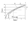
図6は、本発明が適用されるエレベータ装置の下降運転時における検出板速度検出特性とエンコーダ速度検出特性を示す図である。図6において、横軸は昇降体1の下降方向の移動距離(m)、縦軸は走行速度(m/min)を示す。
[Detection plate speed detection characteristics and encoder speed detection characteristics]
FIG. 6 is a diagram showing a detection plate speed detection characteristic and an encoder speed detection characteristic during the descending operation of the elevator apparatus to which the present invention is applied. In FIG. 6, the horizontal axis represents the moving distance (m) in the descending direction of the lifting body 1, and the vertical axis represents the traveling speed (m / min).

図6において、検出板速度検出特性27は、故障検出用センサ24が回転検出板23の回転に応じて出力する信号を元に算出される、昇降体1の走行速度と移動距離との関係を示したものである。また、エンコーダ速度検出特性28は、ロータリエンコーダ19が出力するエンコーダ信号を元に算出される、昇降体1の走行速度と移動距離との関係を示したものである。   In FIG. 6, the detection plate speed detection characteristic 27 indicates the relationship between the traveling speed and the moving distance of the lifting body 1 calculated based on the signal output by the failure detection sensor 24 according to the rotation of the rotation detection plate 23. It is shown. The encoder speed detection characteristic 28 indicates the relationship between the traveling speed and the moving distance of the lifting body 1 calculated based on the encoder signal output from the rotary encoder 19.

回転検出板23が回転することにより、相対的に故障検出用センサ24の検出点26が回転検出板23上を移動し、その軌跡は円弧となる。回転検出板23の回転中心から故障検出用センサ24の検出点26までの距離r(図5参照)によって、検出点26の軌跡である半円の円弧23Cの長さ(移動距離L0)が決まる。そして、円弧23Cの長さ、第2ローラ21と第1ローラ20の径などから、回転検出板23が半回転(180度回転)するときの第1ローラ20の回転数がわかり、調速用ロープ8(昇降体1)の移動距離が求められる。このように、円弧23Cの長さ(移動距離L0)が分かり、検出板速度検出特性27では、昇降体1が移動距離L0に対応する距離を移動するごとに走行速度の更新が発生する。   As the rotation detection plate 23 rotates, the detection point 26 of the failure detection sensor 24 relatively moves on the rotation detection plate 23, and its locus becomes an arc. The length (movement distance L0) of the semicircular arc 23C that is the locus of the detection point 26 is determined by the distance r (see FIG. 5) from the rotation center of the rotation detection plate 23 to the detection point 26 of the failure detection sensor 24. . Then, from the length of the arc 23C, the diameters of the second roller 21 and the first roller 20, and the like, the number of rotations of the first roller 20 when the rotation detection plate 23 makes a half rotation (180 degree rotation) can be known. The moving distance of the rope 8 (elevating body 1) is obtained. Thus, the length of the arc 23C (movement distance L0) is known, and in the detection plate speed detection characteristic 27, the travel speed is updated every time the lifting body 1 moves a distance corresponding to the movement distance L0.

図6に示すように、昇降体1の走行速度が低いときは、検出板速度検出特性27とエンコーダ速度検出特性28との差(差分d)が大きい。他方、昇降体1の走行速度が高速になるにつれて故障検出用センサ24から出力される出力信号のオン/オフの切り替えが頻繁に発生するため、検出板速度検出特性27とエンコーダ速度検出特性28との誤差が小さくなり、検出精度が高まることが分かる。そこで、上述した故障検出装置30による故障検出は、エンコーダ速度検出特性28による走行速度が望ましい値、例えば200m/minとなったタイミングで行うようにすることが望ましい。しかし、この望ましい走行速度の値に限らず、望ましい走行速度を中心として所定幅の領域29内の他の走行速度を設定して、クラッチ17の正常/異常の判定を行うことができる。または、上述した走行速度よりも小さな任意の走行速度を設定してもよい。   As shown in FIG. 6, when the traveling speed of the lifting body 1 is low, the difference (difference d) between the detection plate speed detection characteristic 27 and the encoder speed detection characteristic 28 is large. On the other hand, since the on / off switching of the output signal output from the failure detection sensor 24 frequently occurs as the traveling speed of the elevating body 1 increases, the detection plate speed detection characteristic 27, the encoder speed detection characteristic 28, It can be seen that the detection error is reduced and the detection accuracy is increased. Therefore, it is desirable that the above-described failure detection by the failure detection device 30 is performed at a timing when the traveling speed by the encoder speed detection characteristic 28 is a desired value, for example, 200 m / min. However, it is possible to determine whether the clutch 17 is normal or abnormal by setting other travel speeds in the region 29 having a predetermined width around the desired travel speed as well as the desired travel speed value. Alternatively, an arbitrary traveling speed smaller than the traveling speed described above may be set.

[制御系の構成]
本発明が適用されるエレベータ装置の制御系の構成について説明する。
[Control system configuration]
The configuration of the control system of the elevator apparatus to which the present invention is applied will be described.

図7は、本発明が適用されるエレベータ装置の制御系の構成例の概略を示すブロック図である。
図7に示すように、本制御系は、本発明が適用されるエレベータ装置の全体の制御を担う制御部である電子安全コントローラ200を中心として構成されている。電子安全コントローラ200として、例えばマイクロコンピュータを用いることができる。電子安全コントローラ200には、ロータリエンコーダ19の出力信号(エンコーダ信号)、故障検出用センサ24の出力信号が入力される。
FIG. 7 is a block diagram showing an outline of a configuration example of a control system of an elevator apparatus to which the present invention is applied.
As shown in FIG. 7, the present control system is configured around an electronic safety controller 200 that is a control unit responsible for overall control of the elevator apparatus to which the present invention is applied. As the electronic safety controller 200, for example, a microcomputer can be used. The electronic safety controller 200 receives the output signal (encoder signal) of the rotary encoder 19 and the output signal of the failure detection sensor 24.

ロータリエンコーダ19は、昇降体1の走行速度を電気的に計測するために用いられる速度センサの一例であり、水平軸12の回転方向の機械的な変位量をデジタル量に変換したエンコーダ信号を出力する。このエンコーダ信号には、水平軸12の回転速度および回転方向の各情報が含まれている。   The rotary encoder 19 is an example of a speed sensor used to electrically measure the traveling speed of the elevating body 1 and outputs an encoder signal obtained by converting a mechanical displacement amount in the rotation direction of the horizontal shaft 12 into a digital amount. To do. This encoder signal includes information on the rotational speed and direction of the horizontal shaft 12.

故障検出用センサ24は、出力側24aと入力側24bとの間における回転検出板23の有無に応じた出力信号、即ち回転検出板23の回転の状態に応じた出力信号を出力する。   The failure detection sensor 24 outputs an output signal according to the presence or absence of the rotation detection plate 23 between the output side 24a and the input side 24b, that is, an output signal according to the rotation state of the rotation detection plate 23.

図7では、電子安全コントローラ200について、電子安全コントローラ200が持つ各機能をブロック図化して機能ブロック図として示している。電子安全コントローラ200は、速度情報処理部201、回転検出カウンタ202、不回転検出カウンタ203、回転判定部204、及び故障判定部205を有している。また、電子安全コントローラ200は、メモリ206を備えている。メモリ206は不揮発メモリであり、例えばデータの書き込み及び読み出しが可能な半導体メモリを用いて構成される。   In FIG. 7, regarding the electronic safety controller 200, each function of the electronic safety controller 200 is shown as a block diagram and shown as a functional block diagram. The electronic safety controller 200 includes a speed information processing unit 201, a rotation detection counter 202, a non-rotation detection counter 203, a rotation determination unit 204, and a failure determination unit 205. The electronic safety controller 200 includes a memory 206. The memory 206 is a non-volatile memory, and is configured using, for example, a semiconductor memory capable of writing and reading data.

速度情報処理部201は、ロータリエンコーダ19のエンコーダ信号に含まれる水平軸12の回転速度および回転方向の各情報に基づいて、昇降体1の走行速度および走行方向を算出する。また、速度情報処理部201は、故障検出用センサ24の出力信号を所定の周期で受信する処理を行い、該出力信号に基づいて回転検出板23の回転/不回転を検出する。本明細書において、不回転とは、回転検出板23が停止状態又は極ゆっくり回転している状態をいう。回転検出板23がこのような状態にある場合には、故障検出用センサ24の受信信号(オン/オフの状態)に変化が現れないため、不回転と検出される。この回転検出板23の回転の情報は回転検出カウンタ202に供給され、不回転の情報は不回転検出カウンタ203に供給される。さらに、速度情報処理部201は、ロータリエンコーダ19のエンコーダ信号に基づいて昇降体1の走行速度を算出する。   The speed information processing unit 201 calculates the traveling speed and the traveling direction of the lifting body 1 based on the information about the rotational speed and the rotational direction of the horizontal shaft 12 included in the encoder signal of the rotary encoder 19. Further, the speed information processing unit 201 performs a process of receiving an output signal of the failure detection sensor 24 at a predetermined cycle, and detects rotation / non-rotation of the rotation detection plate 23 based on the output signal. In the present specification, non-rotation means a state in which the rotation detection plate 23 is stopped or is rotating extremely slowly. When the rotation detection plate 23 is in such a state, no change appears in the reception signal (on / off state) of the failure detection sensor 24, and therefore it is detected as non-rotation. Information about the rotation of the rotation detection plate 23 is supplied to the rotation detection counter 202, and information about the non-rotation is supplied to the non-rotation detection counter 203. Further, the speed information processing unit 201 calculates the traveling speed of the lifting body 1 based on the encoder signal of the rotary encoder 19.

また、速度情報処理部201は、故障検出用センサ24の出力信号を元に算出される昇降体1の現在(最新)の走行速度と、前回算出された昇降体1の走行速度とを比較し、現在の走行速度と前回算出された走行速度とが異なる場合に、回転検出板23が回転していると判定する。ここで、前回の走行速度とは、現在(最新)の走行速度が算出された回転検出板23の状態から半回転前の状態のときに得られた、過去の走行速度のことである。なお、以降の説明において、昇降体1の「現在の走行速度」を、「今回の走行速度」と記すことがある。   The speed information processing unit 201 compares the current (latest) traveling speed of the lifting body 1 calculated based on the output signal of the failure detection sensor 24 with the traveling speed of the lifting body 1 calculated last time. When the current traveling speed is different from the previously calculated traveling speed, it is determined that the rotation detection plate 23 is rotating. Here, the previous travel speed is a past travel speed obtained in a state before the half rotation from the state of the rotation detection plate 23 where the current (latest) travel speed is calculated. In the following description, the “current traveling speed” of the lifting body 1 may be referred to as “current traveling speed”.

さらに、速度情報処理部201は、故障検出用センサ24の出力信号に基づき今回算出された昇降体1の走行速度と、ロータリエンコーダ19のエンコーダ信号に基づき算出される昇降体1の走行速度との差が、所定のしきい値以下であるかどうかを判定する。その判定結果は、回転検出カウンタ202又は不回転検出カウンタ203に供給される。   Further, the speed information processing unit 201 calculates the traveling speed of the lifting body 1 calculated this time based on the output signal of the failure detection sensor 24 and the traveling speed of the lifting body 1 calculated based on the encoder signal of the rotary encoder 19. It is determined whether the difference is less than or equal to a predetermined threshold value. The determination result is supplied to the rotation detection counter 202 or the non-rotation detection counter 203.

なお、電子安全コントローラ200では、速度情報処理部201がロータリエンコーダ19のエンコーダ信号及び故障検出用センサ24の出力信号のそれぞれを元に昇降体1の走行速度を算出しているがこの例に限られない。ロータリエンコーダ19用の速度情報処理部と故障検出用センサ24用の速度情報処理部を別に設けてもよい。   In the electronic safety controller 200, the speed information processing unit 201 calculates the traveling speed of the elevator 1 based on each of the encoder signal of the rotary encoder 19 and the output signal of the failure detection sensor 24. I can't. A speed information processing unit for the rotary encoder 19 and a speed information processing unit for the failure detection sensor 24 may be provided separately.

回転検出カウンタ202は、速度情報処理部201から回転の情報が供給された場合に、カウント値を1だけ増加させ(カウントアップ)、該カウント値を回転判定部204に供給する。回転検出カウンタ202は、カウント値が所定値(例えば8)以上となったらリセットする。   When rotation information is supplied from the speed information processing unit 201, the rotation detection counter 202 increases the count value by 1 (counts up) and supplies the count value to the rotation determination unit 204. The rotation detection counter 202 is reset when the count value becomes a predetermined value (for example, 8) or more.

不回転検出カウンタ203は、速度情報処理部201から不回転の情報が供給された場合に、カウント値を1だけ増加させ(カウントアップ)、カウント値を回転判定部204に供給する。不回転検出カウンタ203は、カウント値が所定値(例えば8)以上となったらリセットする。回転検出カウンタ202と不回転検出カウンタ203は、他方の検出カウンタがリセット動作を行うときには自身の検出カウンタもリセットする。   When non-rotation information is supplied from the speed information processing unit 201, the non-rotation detection counter 203 increases the count value by 1 (counts up) and supplies the count value to the rotation determination unit 204. The non-rotation detection counter 203 is reset when the count value becomes a predetermined value (for example, 8) or more. The rotation detection counter 202 and the non-rotation detection counter 203 also reset their own detection counter when the other detection counter performs a reset operation.

回転判定部204は、回転検出カウンタ202又は不回転検出カウンタ203のいずれかのカウント値が所定値(例えば8)未満であるか否かを判定基準として、回転検出板23の回転又は不回転を判定する。判定結果は、故障判定部205に供給される。なお、上述した回転検出カウンタ202と不回転検出カウンタ203のリセット動作は、回転判定部204がリセット指令を出力することにより行われるようにしてもよい。   The rotation determination unit 204 determines whether the rotation detection plate 23 is rotated or not rotated based on whether or not the count value of either the rotation detection counter 202 or the non-rotation detection counter 203 is less than a predetermined value (for example, 8). judge. The determination result is supplied to the failure determination unit 205. The above-described reset operation of the rotation detection counter 202 and the non-rotation detection counter 203 may be performed by the rotation determination unit 204 outputting a reset command.

故障判定部205は、回転判定部204から供給される回転検出板23の回転又は不回転についての判定結果と、速度情報処理部201から供給される昇降体1の走行方向の情報とに基づいて、クラッチ17の正常/異常を判定する。具体的には、故障判定部205は、昇降体1が上昇かつ回転検出板23が回転している、又は昇降体1が下降かつ回転検出板23が不回転である場合には、クラッチ17は異常であると判定する。また、故障判定部205は、昇降体1が上昇かつ回転検出板23が不回転である、又は昇降体1が下降かつ回転検出板23が回転している場合には、クラッチ17は正常であると判定する。判定結果は、制御盤103に供給される。   The failure determination unit 205 is based on the determination result about the rotation or non-rotation of the rotation detection plate 23 supplied from the rotation determination unit 204 and the traveling direction information of the elevator 1 supplied from the speed information processing unit 201. Then, it is determined whether the clutch 17 is normal or abnormal. Specifically, the failure determination unit 205 determines that the clutch 17 is in the case where the elevating body 1 is raised and the rotation detection plate 23 is rotating, or the elevating body 1 is lowered and the rotation detection plate 23 is not rotating. Judged to be abnormal. Further, the failure determination unit 205 indicates that the clutch 17 is normal when the elevating body 1 is raised and the rotation detection plate 23 is not rotated, or when the elevating body 1 is lowered and the rotation detection plate 23 is rotating. Is determined. The determination result is supplied to the control panel 103.

上述した電子安全コントローラ200の各機能部201〜205については、プロセッサがそれぞれの機能を実現するプログラムを解釈し、実行することにより、ソフトウェアで実現することができる。このとき、各機能を実現するプログラム、テーブル、ファイル等の情報は、メモリ206、もしくはハードディスク、SSD(Solid State Drive)等の記録装置、または、ICカード、SDカード、DVD等の記録媒体に記録することができる。また、上記の各機能部201〜205などについては、それらの一部または全部を、例えば集積回路で設計する等により、ハードウェアで実現することもできる。   The functional units 201 to 205 of the electronic safety controller 200 described above can be realized by software by the processor interpreting and executing a program that realizes each function. At this time, information such as programs, tables, and files for realizing each function is recorded in the memory 206, a recording device such as a hard disk or SSD (Solid State Drive), or a recording medium such as an IC card, SD card, or DVD. can do. Moreover, about each said function parts 201-205 etc., those parts or all can also be implement | achieved by hardware, for example by designing with an integrated circuit.

[故障検出処理手順]
図8は、本発明が適用されるエレベータ装置の制御系による故障検出処理手順の一例を示すフローチャートである。
図8に示す故障検出処理は、電子安全コントローラ200のプロセッサ(マイクロコンピュータ)が、メモリ206に格納されたプログラムを読み出して実行することにより実現される。本フローチャートの前提条件として、正常時におけるエレベータ装置の上昇運転時には第2の調速機15の回転体18への綱車9aの回転の伝達が解除され、回転検出板23は停止状態である。また、下降運転時には綱車9aの回転がクラッチ17を介して第2の調速機15の回転体18に伝達され、回転検出板23は回転する。
[Fault detection procedure]
FIG. 8 is a flowchart showing an example of a failure detection processing procedure by the control system of the elevator apparatus to which the present invention is applied.
The failure detection process shown in FIG. 8 is realized by the processor (microcomputer) of the electronic safety controller 200 reading and executing a program stored in the memory 206. As a precondition of this flowchart, transmission of the rotation of the sheave 9a to the rotating body 18 of the second speed governor 15 is released during the ascending operation of the elevator apparatus at normal time, and the rotation detection plate 23 is in a stopped state. Further, during the descent operation, the rotation of the sheave 9a is transmitted to the rotating body 18 of the second speed governor 15 via the clutch 17, and the rotation detection plate 23 rotates.

エレベータ装置が稼動し、制御盤103が昇降体1の走行を開始すると(ステップS1)、まず、速度情報処理部201は、ロータリエンコーダ19のエンコーダ信号から算出される走行速度(以下「ロータリエンコーダ19の速度検出値」と記す。)が、所定のしきい値、例えば200m/minに達したか否かを判定する(ステップS2)。そして、速度情報処理部201は、ロータリエンコーダ19の速度検出値が200m/minに達している場合には(ステップS2のYES)、ステップS3の処理に移行する。また、ロータリエンコーダ19の速度検出値が200m/minに達していない場合には(ステップS2のNO)、ロータリエンコーダ19の速度検出値が所定のしきい値に達するまで本ステップの判定処理を継続する。   When the elevator apparatus is operated and the control panel 103 starts traveling of the elevator body 1 (step S1), first, the speed information processing unit 201 first calculates the traveling speed calculated from the encoder signal of the rotary encoder 19 (hereinafter referred to as “rotary encoder 19”). It is determined whether or not a predetermined threshold value, for example, 200 m / min, has been reached (step S2). Then, when the speed detection value of the rotary encoder 19 has reached 200 m / min (YES in step S2), the speed information processing unit 201 proceeds to the process in step S3. If the speed detection value of the rotary encoder 19 has not reached 200 m / min (NO in step S2), the determination process in this step is continued until the speed detection value of the rotary encoder 19 reaches a predetermined threshold value. To do.

次に、速度情報処理部201は、回転検出板23を用いた速度検出値が発生しているか否かを判定する(ステップS3)。即ち、速度情報処理部201は、故障検出用センサ24の出力信号を所定の周期で受信する処理を行い、故障検出用センサ24の出力信号に基づいて走行速度(以下「回転検出板23による速度検出値」と記す。)が算出できたかどうかを判定する。ここで、速度情報処理部201は、走行速度を算出できなかった場合には回転検出板23は不回転であると判定し(ステップS3のNO)、不回転検出カウンタ203をカウントアップする(ステップS4)。一方、速度情報処理部201は、走行速度が算出できた場合には回転検出板23は回転していると判定し(ステップS3のYES)、ステップS7へ移行する。   Next, the speed information processing unit 201 determines whether or not a speed detection value using the rotation detection plate 23 is generated (step S3). That is, the speed information processing unit 201 performs processing for receiving the output signal of the failure detection sensor 24 at a predetermined cycle, and based on the output signal of the failure detection sensor 24, the traveling speed (hereinafter referred to as “speed by the rotation detection plate 23). It is determined whether or not “detected value” is calculated. Here, when the traveling speed cannot be calculated, the speed information processing unit 201 determines that the rotation detection plate 23 is not rotating (NO in Step S3), and counts up the non-rotation detection counter 203 (Step S3). S4). On the other hand, when the traveling speed can be calculated, the speed information processing unit 201 determines that the rotation detection plate 23 is rotating (YES in step S3), and proceeds to step S7.

その後、回転判定部204は、不回転検出カウンタ203のカウント値が、所定値例えば8回未満か否かを判定し(ステップS5)、8回未満であれば(ステップS5のYES)、再びステップS3に戻って同じ処理を繰り返す。一方、回転判定部204は、不回転検出カウンタ203のカウント値が8回以上である場合には(ステップS5のNO)、回転検出板23が不回転であると判定する(ステップS6)。   Thereafter, the rotation determination unit 204 determines whether or not the count value of the non-rotation detection counter 203 is less than a predetermined value, for example, 8 times (step S5), and if it is less than 8 times (YES in step S5), the step again Returning to S3, the same processing is repeated. On the other hand, when the count value of the non-rotation detection counter 203 is 8 times or more (NO in step S5), the rotation determination unit 204 determines that the rotation detection plate 23 does not rotate (step S6).

上記ステップS3の判定処理で、回転検出板23による速度検出値が算出できた場合には(ステップS3のYES)、速度情報処理部201は、回転検出板23による今回(現在)の速度検出値が前回(半回転前)の速度検出値と異なるか否かを判定する(ステップS7)。その結果、速度情報処理部201は、今回の速度検出値と前回の速度検出値とが異なる場合には(ステップS7のYES)、ステップS8へ移行し、今回の速度検出値と前回の速度検出値とが同じ場合にはステップS3へ戻って同じ処理を繰り返す(ステップS7のNO)。   When the speed detection value by the rotation detection plate 23 can be calculated in the determination process of step S3 (YES in step S3), the speed information processing unit 201 detects the current (current) speed detection value by the rotation detection plate 23. Is different from the speed detection value of the previous time (before half rotation) (step S7). As a result, when the current speed detection value is different from the previous speed detection value (YES in step S7), the speed information processing unit 201 proceeds to step S8, and the current speed detection value and the previous speed detection are detected. If the values are the same, the process returns to step S3 and the same processing is repeated (NO in step S7).

上記ステップS7の判定処理で、今回の速度検出値と前回の速度検出値とが異なる場合には(ステップS7のYES)、速度情報処理部201は、ロータリエンコーダ19の速度検出値と回転検出板23による速度検出値との差(図6の差分d)が所定のしきい値以下であるか否かを判定する(ステップS8)。所定のしきい値は、例えば30m/minである。両者の差分dが30m/min以下である場合には(ステップS8のYES)、速度情報処理部201は、回転検出カウンタ202をカウントアップさせる(ステップS9)。一方、両者の差分dが30m/minを超える場合には(ステップS8のNO)、速度情報処理部201は、ステップS4に移行して不回転検出カウンタ203をカウントアップさせる。   If the current speed detection value and the previous speed detection value are different in the determination process of step S7 (YES in step S7), the speed information processing unit 201 determines the speed detection value of the rotary encoder 19 and the rotation detection plate. It is determined whether or not the difference from the speed detection value by 23 (difference d in FIG. 6) is equal to or smaller than a predetermined threshold value (step S8). The predetermined threshold is, for example, 30 m / min. If the difference d between the two is 30 m / min or less (YES in step S8), the speed information processing unit 201 increments the rotation detection counter 202 (step S9). On the other hand, when the difference d between the two exceeds 30 m / min (NO in step S8), the speed information processing unit 201 proceeds to step S4 and increments the non-rotation detection counter 203.

次に、回転判定部204は、回転検出カウンタ202のカウント値が、所定値例えば8回未満か否かを判定し(ステップS10)、8回未満であれば(ステップS10のYES)、再びステップS3に戻って同じ処理を繰り返す。一方、回転判定部204は、回転検出カウンタ202のカウント値が8回以上である場合には(ステップS10のNO)、回転検出板23が回転していると判定する(ステップS11)。   Next, the rotation determination unit 204 determines whether or not the count value of the rotation detection counter 202 is less than a predetermined value, for example, 8 times (step S10), and if it is less than 8 times (YES in step S10), the step again Returning to S3, the same processing is repeated. On the other hand, when the count value of the rotation detection counter 202 is 8 times or more (NO in step S10), the rotation determination unit 204 determines that the rotation detection plate 23 is rotating (step S11).

その後、ステップS6又はステップS11の判定結果を受けて、故障判定部205は、速度情報処理部201がロータリエンコーダ19のエンコーダ信号に基づいて算出した昇降体1の走行方向の情報に基づき、昇降体1の走行方向を判定する(ステップS12)。   Thereafter, in response to the determination result of step S6 or step S11, the failure determination unit 205 determines whether the speed information processing unit 201 is based on the traveling direction information of the lifting body 1 calculated based on the encoder signal of the rotary encoder 19. 1 traveling direction is determined (step S12).

そして、故障判定部205は、故障判定部205は、昇降体1が上昇かつ回転検出板23が不回転である、又は昇降体1が下降かつ回転検出板23が回転している場合には、クラッチ17は正常であるとして、本故障検出処理を終了する。また、故障判定部205は、昇降体1が上昇かつ回転検出板23が回転している、又は昇降体1が下降かつ回転検出板23が不回転である場合には、クラッチ17は異常であると判定し、その判定結果を制御盤103に出力する。制御盤103(電子安全システム)は、クラッチ17は異常であるという判定結果を受けて、昇降体1を最寄り階に休止させる等の適切な制御を行う。   Then, the failure determination unit 205 determines that the failure determination unit 205 is in the case where the lifting body 1 is raised and the rotation detection plate 23 is not rotated, or the lifting body 1 is lowered and the rotation detection plate 23 is rotating. The failure detection process is terminated assuming that the clutch 17 is normal. The failure determination unit 205 indicates that the clutch 17 is abnormal when the lifting body 1 is raised and the rotation detection plate 23 is rotating, or when the lifting body 1 is lowered and the rotation detection plate 23 is not rotating. And the determination result is output to the control panel 103. In response to the determination result that the clutch 17 is abnormal, the control panel 103 (electronic safety system) performs appropriate control such as stopping the elevator 1 at the nearest floor.

以上説明したように、第1の実施の形態に係るエレベータ装置では、故障検出装置30の第2の調速機15の回転体18と同期して回転する回転検出板23が回転しているか否かの判定を行っている。そして、回転/不回転の判定結果と、ロータリエンコーダ19のエンコーダ信号を元に算出される昇降体1の走行方向の情報に基づいて、クラッチの正常/異常を判定している。それにより、図6において説明した昇降体1等の振動による断続的遮蔽現象を排除して、第2の調速機15の回転体18に対して回転の伝達又は解除を行うクラッチ17の正常/異常、即ちクラッチ17の故障を精度良く検出することができる。   As described above, in the elevator apparatus according to the first embodiment, whether or not the rotation detection plate 23 that rotates in synchronization with the rotating body 18 of the second governor 15 of the failure detection apparatus 30 is rotating. Judgment is made. Based on the rotation / non-rotation determination result and information on the traveling direction of the lifting body 1 calculated based on the encoder signal of the rotary encoder 19, the normal / abnormal clutch is determined. Thereby, the intermittent shielding phenomenon due to the vibration of the lifting body 1 and the like described in FIG. 6 is excluded, and the normal / normal state of the clutch 17 that transmits or releases the rotation to the rotating body 18 of the second governor 15. Abnormality, that is, failure of the clutch 17 can be accurately detected.

さらに、第1の実施の形態では、回転検出板23の回転/不回転の判定精度を高めるための処理を有する。例えば、回転検出板23による速度検出値とロータリエンコーダ19の速度検出値とを比較することにより、回転検出板23の回転/不回転の検出精度を高めることができる。特に、図6に示したように、回転検出板23による速度検出値が低いときは、ロータリエンコーダ19の速度検出値との差が大きいため、回転検出板23による速度検出値の誤差が大きくなる。そこで、回転検出板23による速度検出値とロータリエンコーダ19の速度検出値との差が小さくなるような所定のしきい値(例えば200m/min)を設定している(ステップS2参照)。ロータリエンコーダ19による速度検出値がこのしきい値に達したときに両者の比較を開始することで、回転検出板23の回転/不回転の検出精度が向上する。なお、ステップS2の処理は望ましい形態であるが、省略することができる。   Furthermore, in the first embodiment, there is a process for increasing the accuracy of determination of rotation / non-rotation of the rotation detection plate 23. For example, by comparing the speed detection value of the rotation detection plate 23 with the speed detection value of the rotary encoder 19, the detection accuracy of rotation / non-rotation of the rotation detection plate 23 can be increased. In particular, as shown in FIG. 6, when the speed detection value by the rotation detection plate 23 is low, an error in the speed detection value by the rotation detection plate 23 increases because the difference from the speed detection value of the rotary encoder 19 is large. . Therefore, a predetermined threshold value (for example, 200 m / min) is set such that the difference between the speed detection value by the rotation detection plate 23 and the speed detection value of the rotary encoder 19 is small (see step S2). When the speed detection value by the rotary encoder 19 reaches this threshold value, the comparison between the two is started, so that the detection accuracy of rotation / non-rotation of the rotation detection plate 23 is improved. In addition, although the process of step S2 is a desirable form, it can be abbreviate | omitted.

また、第1の実施の形態では、回転検出カウンタ202(不回転検出カウンタ203)を8回カウントアップさせて判定精度を高めている(ステップS5,S10参照)。仮にステップS3で故障検出用センサ24から出力された出力信号にノイズが混入して回転検出板23による速度検出値を誤検出したとしても、判定を繰り返すうちに速度検出値が変化するため、「回転している」と判定させないようにすることができる。それゆえ、最終的に回転検出板23の回転の誤検出を防止できる。なお、ステップS4,S5,S9,S10の処理は望ましい形態であるが、省略することができる。   In the first embodiment, the rotation detection counter 202 (non-rotation detection counter 203) is counted up eight times to improve the determination accuracy (see steps S5 and S10). Even if noise is mixed into the output signal output from the failure detection sensor 24 in step S3 and the speed detection value detected by the rotation detection plate 23 is erroneously detected, the speed detection value changes as the determination is repeated. It is possible to prevent the determination that “rotating”. Therefore, it is possible to prevent erroneous detection of the rotation of the rotation detection plate 23 in the end. In addition, although the process of step S4, S5, S9, S10 is a desirable form, it can be abbreviate | omitted.

また、第1の実施の形態では、回転検出板23による今回の速度検出値が前回(半回転前)の速度検出値と異なるか否かを判定している(ステップS7参照)。このような構成により、回転検出板23の回転/不回転の検出精度を向上させることができる。なお、ステップS7の処理は望ましい形態であるが、省略することができる。   Further, in the first embodiment, it is determined whether or not the current speed detection value by the rotation detection plate 23 is different from the previous (half rotation) speed detection value (see step S7). With such a configuration, the rotation / non-rotation detection accuracy of the rotation detection plate 23 can be improved. In addition, although the process of step S7 is a desirable form, it can be abbreviate | omitted.

さらに、第1の実施の形態では、ロータリエンコーダ19の速度検出値と回転検出板23による速度検出値との差が所定のしきい値以下であるか否かを判定している(ステップS8参照)。このような構成により、回転検出板23の回転/不回転の検出精度を向上させることができる。なお、ステップS8の処理は望ましい形態であるが、省略することができる。   Furthermore, in the first embodiment, it is determined whether or not the difference between the speed detection value of the rotary encoder 19 and the speed detection value of the rotation detection plate 23 is equal to or less than a predetermined threshold value (see step S8). ). With such a configuration, the rotation / non-rotation detection accuracy of the rotation detection plate 23 can be improved. In addition, although the process of step S8 is a desirable form, it can be abbreviate | omitted.

一般に、ロータリエンコーダは高価である。仮に、回転検出板23と故障検出用センサ24をロータリエンコーダに代えると、ロータリエンコーダ19と合わせて第2の調速機15側にロータリエンコーダが2個となりコストが増大する。しかし、本実施の形態では、回転検出板23と故障検出用センサ24を用いることにより、コストの増大を抑え安価な構成でクラッチ17の故障を検出することができる。   Generally, a rotary encoder is expensive. If the rotation detection plate 23 and the failure detection sensor 24 are replaced with a rotary encoder, two rotary encoders are provided on the second speed governor 15 side together with the rotary encoder 19 and the cost increases. However, in the present embodiment, by using the rotation detection plate 23 and the failure detection sensor 24, the failure of the clutch 17 can be detected with an inexpensive configuration while suppressing an increase in cost.

<2.第2の実施の形態>
次に、本発明が適用されるエレベータ装置の故障検出装置に用いられる回転検出板の他の例を説明する。
<2. Second Embodiment>
Next, another example of the rotation detection plate used in the failure detection apparatus for an elevator apparatus to which the present invention is applied will be described.

図9は、本発明が適用されるエレベータ装置の第2の実施の形態に係る調速機10の要部の平面図である。
本実施の形態に係る回転検出板31は、円盤状の本体32を有し、本体32の一部に半円形の孔部33(半円形状部の一例)が形成されている。回転検出板31の回転中心は、第2ローラ21の回転軸と一致している。
FIG. 9 is a plan view of a main part of the governor 10 according to the second embodiment of the elevator apparatus to which the present invention is applied.
The rotation detection plate 31 according to the present embodiment has a disc-shaped main body 32, and a semicircular hole 33 (an example of a semicircular portion) is formed in a part of the main body 32. The rotation center of the rotation detection plate 31 coincides with the rotation axis of the second roller 21.

このような構成とすることにより、回転検出板31が半回転(180度回転)する度に、故障検出用センサ24の出力側24aと入力側24bとの間を通過する本体32の位置(孔部33とそれ以外の部分)が切り替わる。よって、回転検出板31を用いた場合でも、回転検出板23の場合と同様に、回転検出板31が半回転する度に、故障検出用センサ24が出力する信号のオン/オフが切り替わる。また、回転検出板23の回転中心から故障検出用センサ24の検出点26までの距離rは、図5に示す回転検出板23及び故障検出用センサ24の場合と同じとすることができる。したがって、本実施の形態においても、距離rによって、回転検出板23上の検出点26の軌跡である半円の円弧の長さ(移動距離L0)が決まる。   With such a configuration, the position (hole) of the main body 32 that passes between the output side 24a and the input side 24b of the failure detection sensor 24 every time the rotation detection plate 31 makes a half rotation (180 degree rotation). The part 33 and the other part) are switched. Therefore, even when the rotation detection plate 31 is used, as in the case of the rotation detection plate 23, each time the rotation detection plate 31 rotates halfway, the signal output from the failure detection sensor 24 is switched on / off. Further, the distance r from the rotation center of the rotation detection plate 23 to the detection point 26 of the failure detection sensor 24 can be the same as that of the rotation detection plate 23 and the failure detection sensor 24 shown in FIG. Therefore, also in the present embodiment, the length of the semicircular arc (movement distance L0) that is the locus of the detection point 26 on the rotation detection plate 23 is determined by the distance r.

以上説明したように、第2の実施の形態によれば、回転検出板23(図4参照)の場合と同様に、回転検出板31が半回転する度に、故障検出用センサ24の出力信号のオン/オフが切り替わる。また、回転検出板31の本体32の形状は円盤状であり、外周端に角部がない。そのため、回転検出板31が回転した場合における安全性が向上する。   As described above, according to the second embodiment, as in the case of the rotation detection plate 23 (see FIG. 4), the output signal of the failure detection sensor 24 every time the rotation detection plate 31 makes a half rotation. Is switched on / off. Further, the shape of the main body 32 of the rotation detection plate 31 is a disk shape, and there is no corner at the outer peripheral end. Therefore, the safety when the rotation detection plate 31 rotates is improved.

なお、本実施の形態では、回転検出板31に形成した孔部の数は1つであるが、2以上の孔部を形成してもよい。回転検出板に形成する孔部の数や形状は、故障検出用センサ24の出力側24aから射出された信号を、回転検出板の回転に応じて周期的に繰り返し検出できる構成であればよい。   In the present embodiment, the number of holes formed in the rotation detection plate 31 is one, but two or more holes may be formed. The number and shape of the holes formed in the rotation detection plate may be any configuration as long as the signal emitted from the output side 24a of the failure detection sensor 24 can be periodically and repeatedly detected according to the rotation of the rotation detection plate.

<3.第3の実施の形態>
図10は、本発明が適用されるエレベータ装置の第3の実施の形態に係る調速機10の断面図である。
図10に示すように、第2の調速機15側に設けられた故障検出装置30Aにおいて、台座25の軸25aと第2ローラ21との間に、クラッチ41が配置される。クラッチ41は、例えばカム式ワンウェイクラッチ(カムクラッチ)が用いられる。クラッチ41の外輪41bが第2ローラ21に固定され、クラッチ41の内輪41aが台座25の軸25aに固定される。
<3. Third Embodiment>
FIG. 10 is a cross-sectional view of a speed governor 10 according to a third embodiment of an elevator apparatus to which the present invention is applied.
As shown in FIG. 10, in the failure detection device 30 </ b> A provided on the second speed governor 15 side, the clutch 41 is disposed between the shaft 25 a of the base 25 and the second roller 21. As the clutch 41, for example, a cam type one-way clutch (cam clutch) is used. The outer ring 41 b of the clutch 41 is fixed to the second roller 21, and the inner ring 41 a of the clutch 41 is fixed to the shaft 25 a of the base 25.

クラッチ41は、昇降体1の下降運転時、伝達系22の回転を第2ローラ21に伝達し、昇降体1の上昇運転時、第2ローラ21への伝達系22の回転の伝達を解除する。即ち、クラッチ41は、昇降体1の下降運転時、伝達系22即ち第1ローラ20と同じ方向に第2ローラ21が回転するようにし、昇降体1の上昇運転時、第2ローラ21が反対方向には回転しないようにする。   The clutch 41 transmits the rotation of the transmission system 22 to the second roller 21 during the lowering operation of the lifting body 1 and releases the transmission of the rotation of the transmission system 22 to the second roller 21 during the lifting operation of the lifting body 1. . That is, the clutch 41 allows the second roller 21 to rotate in the same direction as the transmission system 22, that is, the first roller 20 during the lowering operation of the lifting body 1, and the second roller 21 is opposite during the lifting operation of the lifting body 1. Do not rotate in the direction.

以上説明したように、第3の実施の形態によれば、昇降体1の上昇運転時、クラッチ41によって第2の調速機15の回転体18の回転を阻止することにより、誤検出を防ぎ、信頼性の向上を図ることができる。それ以外は、第1の実施の形態と同様の効果を奏する。また、本実施の形態を、第2の実施の形態と組み合わせてもよい。   As described above, according to the third embodiment, during the ascending operation of the lifting / lowering body 1, the clutch 41 prevents the rotation of the rotating body 18 of the second speed governor 15 to prevent erroneous detection. Reliability can be improved. Other than that, there exists an effect similar to 1st Embodiment. Further, this embodiment may be combined with the second embodiment.

さらに、本発明は上述した各実施の形態例に限られるものではなく、特許請求の範囲に記載した本発明の要旨を逸脱しない限りにおいて、その他種々の応用例、変形例を取り得ることは勿論である。   Furthermore, the present invention is not limited to the embodiments described above, and various other application examples and modifications can of course be taken without departing from the gist of the present invention described in the claims. It is.

例えば、上述した実施の形態例は本発明を分かりやすく説明するために装置及びシステムの構成を詳細且つ具体的に説明したものであり、必ずしも説明した全ての構成を備えるものに限定されるものではない。また、ある実施の形態例の構成の一部を他の実施の形態例の構成に置き換えることは可能である。また、ある実施の形態例の構成に他の実施の形態例の構成を加えることも可能である。また、各実施の形態例の構成の一部について、他の構成の追加、削除、置換をすることも可能である。   For example, the above-described embodiments are detailed and specific descriptions of the configuration of the apparatus and the system in order to explain the present invention in an easy-to-understand manner, and are not necessarily limited to those having all the configurations described. Absent. A part of the configuration of an embodiment can be replaced with the configuration of another embodiment. Further, the configuration of another embodiment can be added to the configuration of one embodiment. Moreover, it is also possible to add, delete, and replace other configurations for a part of the configuration of each embodiment.

また、制御線や情報線は説明上必要と考えられるものを示しており、製品上必ずしも全ての制御線や情報線を示しているとは限らない。実際には殆ど全ての構成が相互に接続されていると考えてもよい。   Further, the control lines and information lines indicate what is considered necessary for the explanation, and not all the control lines and information lines on the product are necessarily shown. Actually, it may be considered that almost all the components are connected to each other.

また、本明細書において、時系列的な処理を記述する処理ステップは、記載された順序に沿って時系列的に行われる処理はもちろん、必ずしも時系列的に処理されなくとも、並列的あるいは個別に実行される処理(例えば、並列処理あるいはオブジェクトによる処理)をも含むものである。   Further, in this specification, the processing steps describing time-series processing are not limited to processing performed in time series according to the described order, but are not necessarily performed in time series, either in parallel or individually. The processing (for example, parallel processing or object processing) is also included.

1…昇降体、 7…連結部材、 8…調速用ロープ、 9a,9b…綱車、 10…調速機、 12…水平軸、 13…第1の調速機、 15…第2の調速機、 17…クラッチ、 18…回転体、 19…ロータリエンコーダ(回転検出用センサ)、 20…第1ローラ、 21…第2ローラ、 22…伝達系、 23,31…回転検出板、 23C…円弧、 24…故障検出用センサ、 24a…出力側、 24b…入力側、 27…エンコーダ速度検出特性、 28…検出板速度検出特性、 29…領域、 32…本体、 33…孔部、 41…クラッチ、 101…機械室、 102…昇降路、 103…制御盤、 200…電子安全コントローラ(制御部)、 201…速度情報処理部、 202…回転検出カウンタ、 203…不回転検出カウンタ、 204…回転判定部、 205…故障判定部、 206…メモリ   DESCRIPTION OF SYMBOLS 1 ... Elevating body, 7 ... Connecting member, 8 ... Speed control rope, 9a, 9b ... Sheave, 10 ... Speed governor, 12 ... Horizontal axis, 13 ... First speed governor, 15 ... Second speed control Speed machine, 17 ... clutch, 18 ... rotating body, 19 ... rotary encoder (rotation detection sensor), 20 ... first roller, 21 ... second roller, 22 ... transmission system, 23, 31 ... rotation detection plate, 23C ... Arc: 24 ... Sensor for detecting failure, 24a ... Output side, 24b ... Input side, 27 ... Encoder speed detection characteristic, 28 ... Detection plate speed detection characteristic, 29 ... Area, 32 ... Main body, 33 ... Hole, 41 ... Clutch 101 ... Machine room, 102 ... Hoistway, 103 ... Control panel, 200 ... Electronic safety controller (control unit), 201 ... Speed information processing unit, 202 ... Rotation detection counter, 203 ... Non-rotation detection counter, 204 ... Rotation determination unit, 205 ... Failure determination unit, 206 ... Memory

Claims (7)

昇降体に連結された調速用ロープと、
水平軸に固定されて前記調速用ロープが巻き掛けられた綱車と、
前記綱車の回転速度を調速し、前記昇降体の上昇過速度を検出する第1の調速機と、
前記昇降体の下降運転時に前記綱車の回転速度を調速し、前記昇降体の下降過速度を検出する第2の調速機と、
前記水平軸と前記第2の調速機とを連結し、前記昇降体の下降運転時に前記綱車の回転を前記第2の調速機の回転体に伝達し、前記昇降体の上昇運転時に前記第2の調速機の回転体への前記綱車の回転の伝達を解除するクラッチと、
前記水平軸の回転を検出し、第1の検出信号を出力する回転検出用センサと、
前記第2の調速機の回転体と同期した回転を行う回転検出板と、
前記回転検出板の回転に応じて第2の検出信号を出力する故障検出用センサと、
前記回転検出用センサから出力された前記第1の検出信号を受信し、また前記故障検出用センサから出力された前記第2の検出信号を受信する制御部と、を備え、
前記制御部は、前記第2の検出信号を用いて前記回転検出板の回転/不回転を判定し、該判定の結果と前記第1の検出信号を元に算出される前記昇降体の走行方向とから前記クラッチの正常/異常を判定す
エレベータ装置。
A speed control rope connected to the lifting body;
A sheave fixed to a horizontal shaft and wrapped around the speed-control rope;
A first governor that regulates the rotational speed of the sheave and detects the overspeed of the lifting body;
A second governor that regulates the rotational speed of the sheave during the descent operation of the elevating body and detects the descent overspeed of the elevating body;
The horizontal shaft and the second speed governor are connected, and the rotation of the sheave is transmitted to the rotating body of the second speed governor during the lowering operation of the lifting body, and during the lifting operation of the lifting body A clutch for releasing transmission of rotation of the sheave to the rotating body of the second governor;
A rotation detection sensor that detects rotation of the horizontal axis and outputs a first detection signal;
A rotation detection plate that rotates in synchronization with the rotating body of the second governor;
A failure detection sensor that outputs a second detection signal in accordance with the rotation of the rotation detection plate;
A controller that receives the first detection signal output from the rotation detection sensor and receives the second detection signal output from the failure detection sensor;
The control unit determines rotation / non-rotation of the rotation detection plate using the second detection signal, and the traveling direction of the lifting body calculated based on the determination result and the first detection signal elevator device you judge the normality / abnormality of said clutch from a.
前記制御部は、前記昇降体が上昇かつ前記回転検出板が回転、又は前記昇降体が下降かつ前記回転検出板が不回転の場合には前記クラッチが異常であると判定し、前記昇降体が上昇かつ前記回転検出板が不回転、又は前記昇降体が下降かつ前記回転検出板が回転の場合には前記クラッチが正常であると判定する
請求項1に記載のエレベータ装置。
Wherein the control unit, the lifting member is raised and the rotation detection plate is rotated, or wherein when the lifting member is lowered and the rotation detection plate is not rotating, it is determined that the clutch is abnormal, the lifting body rise and the rotation detection plate is not rotated, or the elevator apparatus according to claim 1 determines that the lift body is lowered and the rotation detection plate when the rotation is normally the clutch.
前記制御部は、前記回転検出用センサから出力された前記第1の検出信号を元に算出される前記昇降体の第1の走行速度が所定のしきい値以上である場合に、前記第2の検出信号を用いて前記回転検出板の回転/不回転の判定を行う
請求項2に記載のエレベータ装置。
When the first traveling speed of the elevating body calculated based on the first detection signal output from the rotation detection sensor is greater than or equal to a predetermined threshold value, the control unit The elevator apparatus according to claim 2, wherein a rotation / non-rotation determination of the rotation detection plate is performed using the detection signal.
さらに、前記故障検出用センサから出力された前記第2の検出信号に基づいて前記昇降体の第2の走行速度が算出できた場合には前記回転検出板が回転しているとしてカウントアップする回転検出カウンタと、
前記昇降体の前記第2の走行速度が算出できなかった場合には前記回転検出板が回転していないとしてカウントアップする不回転検出カウンタと、を備え、
前記制御部は、前記回転検出カウンタのカウント値が所定値以上である場合に前記回転検出板が回転していると判定し、前記不回転検出カウンタのカウント値が所定値以上である場合に前記回転検出板が不回転であると判定する
請求項2に記載のエレベータ装置。
Further, if the second traveling speed of the lifting body can be calculated based on the second detection signal output from the failure detection sensor, the rotation that counts up as the rotation detection plate is rotating A detection counter;
A non-rotation detection counter that counts up as the rotation detection plate is not rotating when the second traveling speed of the elevating body cannot be calculated ,
Wherein the control unit, the count value of the rotation detection counter is judged to the rotation detection plate is equal to or greater than the predetermined value is rotating, when the count value of the non-rotation detection counter is equal to or greater than a predetermined value The elevator apparatus according to claim 2, wherein the rotation detection plate is determined to be non-rotating.
前記制御部は、前記故障検出用センサから出力された前記第2の検出信号を元に算出される前記昇降体の今回の第2の走行速度と、前回算出された前記昇降体の第2の走行速度とを比較し、今回の前記第2の走行速度と前回算出された前記第2の走行速度とが異なる場合に、前記回転検出板が回転していると判定する
請求項2に記載のエレベータ装置。
The controller is configured to calculate the second traveling speed of the lifting body calculated based on the second detection signal output from the failure detection sensor, and the second traveling speed of the lifting body calculated last time. comparing the running speed, when the current time of the second speed and the calculated pre-times the second running speed differs, in claim 2 judges that the rotation detection plate is rotating The elevator apparatus as described.
前記制御部は、前記故障検出用センサから出力された前記第2の検出信号に基づく前記昇降体の今回の前記第2の走行速度と、前記回転検出用センサから出力された前記第1の検出信号に基づく前記昇降体の第1の走行速度との差が、所定のしきい値以下であるかどうかを判定し、所定のしきい値以下である場合には前記回転検出板が回転していると判定し、前記所定のしきい値を超える場合には前記回転検出板は不回転であると判定する
請求項4又は5に記載のエレベータ装置。
Wherein the control unit is configured and now from the failure detecting sensor of the lifting body based on the output the second detection signal times the second running speed, the output from the rotation detecting sensor of the first It is determined whether or not a difference from the first traveling speed of the elevating body based on the detection signal is equal to or less than a predetermined threshold value. The elevator apparatus according to claim 4 or 5, wherein it is determined that the rotation detection plate is non-rotating when the predetermined threshold value is exceeded.
前記回転検出板は半円形状部を有し、前記故障検出用センサは前記半円形状部の有無を検知することにより前記第2の検出信号を出力する
請求項1に記載のエレベータ装置。
The elevator apparatus according to claim 1, wherein the rotation detection plate has a semicircular portion, and the failure detection sensor outputs the second detection signal by detecting the presence or absence of the semicircular portion.
JP2014242291A 2014-11-28 2014-11-28 Elevator equipment Active JP6295189B2 (en)

Priority Applications (2)

Application Number Priority Date Filing Date Title
JP2014242291A JP6295189B2 (en) 2014-11-28 2014-11-28 Elevator equipment
CN201510837597.XA CN105645219B (en) 2014-11-28 2015-11-26 Lift appliance

Applications Claiming Priority (1)

Application Number Priority Date Filing Date Title
JP2014242291A JP6295189B2 (en) 2014-11-28 2014-11-28 Elevator equipment

Publications (3)

Publication Number Publication Date
JP2016102025A JP2016102025A (en) 2016-06-02
JP2016102025A5 JP2016102025A5 (en) 2017-04-06
JP6295189B2 true JP6295189B2 (en) 2018-03-14

Family

ID=56088934

Family Applications (1)

Application Number Title Priority Date Filing Date
JP2014242291A Active JP6295189B2 (en) 2014-11-28 2014-11-28 Elevator equipment

Country Status (2)

Country Link
JP (1) JP6295189B2 (en)
CN (1) CN105645219B (en)

Cited By (1)

* Cited by examiner, † Cited by third party
Publication number Priority date Publication date Assignee Title
US10925434B2 (en) 2015-09-18 2021-02-23 Franke Kaffeemaschinen Ag Brewing apparatus for preparing a hot beverage

Families Citing this family (2)

* Cited by examiner, † Cited by third party
Publication number Priority date Publication date Assignee Title
CN110054051B (en) * 2019-04-12 2020-10-09 湖北圣信特种设备检测有限公司 Speed sensor and elevator speed limit tester
CN111689325A (en) * 2020-05-19 2020-09-22 上海有个机器人有限公司 Detection method and system for elevator running state, storage medium and intelligent terminal

Family Cites Families (12)

* Cited by examiner, † Cited by third party
Publication number Priority date Publication date Assignee Title
JP2790615B2 (en) * 1994-10-20 1998-08-27 三菱電機株式会社 Elevator governor
CN1157138A (en) * 1997-07-03 1997-08-20 山东鲁北制药厂 Oral liquor using clam extract as main medicinal component and its produsing method
JP4306014B2 (en) * 1999-05-17 2009-07-29 三菱電機株式会社 Governor
JP4137754B2 (en) * 2003-09-29 2008-08-20 株式会社日立製作所 Elevator governor
EP1770044B1 (en) * 2004-07-22 2015-01-28 Mitsubishi Denki Kabushiki Kaisha Speed governor of elevator
WO2009019780A1 (en) * 2007-08-09 2009-02-12 Mitsubishi Electric Corporation Elevator speed governor
JP2009154984A (en) * 2007-12-25 2009-07-16 Mitsubishi Electric Corp Elevator governor
CN102387977B (en) * 2009-04-09 2014-01-29 三菱电机株式会社 Elevator governor
JPWO2012017549A1 (en) * 2010-08-06 2013-09-19 三菱電機株式会社 Elevator governor
JP5850754B2 (en) * 2012-01-24 2016-02-03 株式会社日立製作所 Speed governor and elevator device equipped with the speed governor
JP5809746B2 (en) * 2012-05-21 2015-11-11 株式会社日立製作所 Elevator equipment
DE112013006662T5 (en) * 2013-02-13 2015-12-03 Hitachi, Ltd. winder

Cited By (1)

* Cited by examiner, † Cited by third party
Publication number Priority date Publication date Assignee Title
US10925434B2 (en) 2015-09-18 2021-02-23 Franke Kaffeemaschinen Ag Brewing apparatus for preparing a hot beverage

Also Published As

Publication number Publication date
JP2016102025A (en) 2016-06-02
CN105645219B (en) 2018-05-01
CN105645219A (en) 2016-06-08

Similar Documents

Publication Publication Date Title
JP5247690B2 (en) Elevator safety device
JP4368854B2 (en) Elevator equipment
JP4896873B2 (en) Elevator equipment
JP4907097B2 (en) Elevator equipment
US9708157B2 (en) Controlling speed of an elevator using a speed reducing switch and governor
WO2008062500A1 (en) Elevator system
KR20090055031A (en) Elevator apparatus
JP6058176B2 (en) Elevator equipment
JP6295189B2 (en) Elevator equipment
JPWO2014097373A1 (en) Elevator equipment
CN109850705B (en) Control device for elevator
JP5472473B2 (en) Elevator governor
JP2006290575A (en) Elevator device
JP4412175B2 (en) Elevator governor
WO2018016061A1 (en) Elevator
JP6754715B2 (en) Elevator counterweight clearance diagnostic device
JP6307406B2 (en) Elevator equipment
JP2006298539A (en) Abnormality detecting device for elevator device
WO2019077645A1 (en) Device and method for controlling elevator
JP2014108834A (en) Rope strand rupture detection device for elevator, and method of detecting rope strand rupture
JP5541372B2 (en) Elevator terminal floor forced reduction device
JP4901446B2 (en) Elevator control system
JP6272199B2 (en) Elevator apparatus and electronic safety system inspection method for elevator apparatus
JP6774384B2 (en) Elevator control device and elevator control method
JP2011153010A (en) Elevator device

Legal Events

Date Code Title Description
A521 Written amendment

Free format text: JAPANESE INTERMEDIATE CODE: A523

Effective date: 20170302

A621 Written request for application examination

Free format text: JAPANESE INTERMEDIATE CODE: A621

Effective date: 20170302

A977 Report on retrieval

Free format text: JAPANESE INTERMEDIATE CODE: A971007

Effective date: 20180126

TRDD Decision of grant or rejection written
A01 Written decision to grant a patent or to grant a registration (utility model)

Free format text: JAPANESE INTERMEDIATE CODE: A01

Effective date: 20180206

A61 First payment of annual fees (during grant procedure)

Free format text: JAPANESE INTERMEDIATE CODE: A61

Effective date: 20180219

R150 Certificate of patent or registration of utility model

Ref document number: 6295189

Country of ref document: JP

Free format text: JAPANESE INTERMEDIATE CODE: R150