JP6294455B2 - Trocar cannula assembly having low profile insertion configuration and manufacturing method - Google Patents
Trocar cannula assembly having low profile insertion configuration and manufacturing method Download PDFInfo
- Publication number
- JP6294455B2 JP6294455B2 JP2016502051A JP2016502051A JP6294455B2 JP 6294455 B2 JP6294455 B2 JP 6294455B2 JP 2016502051 A JP2016502051 A JP 2016502051A JP 2016502051 A JP2016502051 A JP 2016502051A JP 6294455 B2 JP6294455 B2 JP 6294455B2
- Authority
- JP
- Japan
- Prior art keywords
- cannula
- balloon
- sleeve
- distal end
- trocar
- Prior art date
- Legal status (The legal status is an assumption and is not a legal conclusion. Google has not performed a legal analysis and makes no representation as to the accuracy of the status listed.)
- Active
Links
- 238000003780 insertion Methods 0.000 title claims description 50
- 230000037431 insertion Effects 0.000 title claims description 50
- 238000004519 manufacturing process Methods 0.000 title claims description 13
- 230000003750 conditioning effect Effects 0.000 claims description 61
- 239000012530 fluid Substances 0.000 claims description 48
- 238000000034 method Methods 0.000 claims description 35
- 239000000463 material Substances 0.000 claims description 34
- 239000000853 adhesive Substances 0.000 claims description 28
- 230000001070 adhesive effect Effects 0.000 claims description 28
- 238000010168 coupling process Methods 0.000 claims description 27
- 230000008878 coupling Effects 0.000 claims description 25
- 238000005859 coupling reaction Methods 0.000 claims description 25
- 238000010438 heat treatment Methods 0.000 claims description 11
- 230000015572 biosynthetic process Effects 0.000 claims description 4
- 238000005520 cutting process Methods 0.000 claims description 2
- 239000011521 glass Substances 0.000 claims description 2
- 230000002093 peripheral effect Effects 0.000 claims description 2
- 229920001187 thermosetting polymer Polymers 0.000 claims description 2
- 238000012544 monitoring process Methods 0.000 claims 2
- 239000007769 metal material Substances 0.000 claims 1
- 239000012815 thermoplastic material Substances 0.000 claims 1
- 230000014759 maintenance of location Effects 0.000 description 23
- 229920000098 polyolefin Polymers 0.000 description 11
- 239000003570 air Substances 0.000 description 9
- 230000008569 process Effects 0.000 description 9
- 230000007704 transition Effects 0.000 description 8
- 238000000071 blow moulding Methods 0.000 description 6
- 230000006641 stabilisation Effects 0.000 description 6
- 238000011105 stabilization Methods 0.000 description 6
- 230000001954 sterilising effect Effects 0.000 description 6
- 238000004659 sterilization and disinfection Methods 0.000 description 6
- 210000003815 abdominal wall Anatomy 0.000 description 5
- 239000000243 solution Substances 0.000 description 5
- 241001631457 Cannula Species 0.000 description 4
- 210000000683 abdominal cavity Anatomy 0.000 description 4
- 230000009467 reduction Effects 0.000 description 4
- 238000007789 sealing Methods 0.000 description 4
- 239000004830 Super Glue Substances 0.000 description 3
- 230000001143 conditioned effect Effects 0.000 description 3
- 230000007547 defect Effects 0.000 description 3
- 235000012489 doughnuts Nutrition 0.000 description 3
- 239000006260 foam Substances 0.000 description 3
- 238000001746 injection moulding Methods 0.000 description 3
- 238000012830 laparoscopic surgical procedure Methods 0.000 description 3
- 230000007246 mechanism Effects 0.000 description 3
- 229920000728 polyester Polymers 0.000 description 3
- 238000001356 surgical procedure Methods 0.000 description 3
- CURLTUGMZLYLDI-UHFFFAOYSA-N Carbon dioxide Chemical compound O=C=O CURLTUGMZLYLDI-UHFFFAOYSA-N 0.000 description 2
- 229920001651 Cyanoacrylate Polymers 0.000 description 2
- 229920002633 Kraton (polymer) Polymers 0.000 description 2
- MWCLLHOVUTZFKS-UHFFFAOYSA-N Methyl cyanoacrylate Chemical compound COC(=O)C(=C)C#N MWCLLHOVUTZFKS-UHFFFAOYSA-N 0.000 description 2
- 238000012084 abdominal surgery Methods 0.000 description 2
- 230000009471 action Effects 0.000 description 2
- 239000012080 ambient air Substances 0.000 description 2
- 238000000418 atomic force spectrum Methods 0.000 description 2
- 238000006243 chemical reaction Methods 0.000 description 2
- 230000001010 compromised effect Effects 0.000 description 2
- 239000013013 elastic material Substances 0.000 description 2
- 208000014674 injury Diseases 0.000 description 2
- 238000002357 laparoscopic surgery Methods 0.000 description 2
- 238000012423 maintenance Methods 0.000 description 2
- 239000012528 membrane Substances 0.000 description 2
- 239000000203 mixture Substances 0.000 description 2
- 230000000149 penetrating effect Effects 0.000 description 2
- 229920000515 polycarbonate Polymers 0.000 description 2
- 239000004417 polycarbonate Substances 0.000 description 2
- -1 polyethylene Polymers 0.000 description 2
- 239000002861 polymer material Substances 0.000 description 2
- 229920002635 polyurethane Polymers 0.000 description 2
- 239000004814 polyurethane Substances 0.000 description 2
- 239000007779 soft material Substances 0.000 description 2
- 239000000126 substance Substances 0.000 description 2
- 230000008733 trauma Effects 0.000 description 2
- 238000003466 welding Methods 0.000 description 2
- 229920002799 BoPET Polymers 0.000 description 1
- 229920002449 FKM Polymers 0.000 description 1
- 239000004677 Nylon Substances 0.000 description 1
- 239000004698 Polyethylene Substances 0.000 description 1
- FAPWRFPIFSIZLT-UHFFFAOYSA-M Sodium chloride Chemical compound [Na+].[Cl-] FAPWRFPIFSIZLT-UHFFFAOYSA-M 0.000 description 1
- 230000003187 abdominal effect Effects 0.000 description 1
- 238000013459 approach Methods 0.000 description 1
- 239000011324 bead Substances 0.000 description 1
- 230000000903 blocking effect Effects 0.000 description 1
- 229910002092 carbon dioxide Inorganic materials 0.000 description 1
- 239000001569 carbon dioxide Substances 0.000 description 1
- 230000008859 change Effects 0.000 description 1
- HGAZMNJKRQFZKS-UHFFFAOYSA-N chloroethene;ethenyl acetate Chemical compound ClC=C.CC(=O)OC=C HGAZMNJKRQFZKS-UHFFFAOYSA-N 0.000 description 1
- 230000006835 compression Effects 0.000 description 1
- 238000007906 compression Methods 0.000 description 1
- 238000010276 construction Methods 0.000 description 1
- 238000004132 cross linking Methods 0.000 description 1
- 238000013461 design Methods 0.000 description 1
- 238000010894 electron beam technology Methods 0.000 description 1
- FGBJXOREULPLGL-UHFFFAOYSA-N ethyl cyanoacrylate Chemical compound CCOC(=O)C(=C)C#N FGBJXOREULPLGL-UHFFFAOYSA-N 0.000 description 1
- 230000004927 fusion Effects 0.000 description 1
- 239000002654 heat shrinkable material Substances 0.000 description 1
- 238000002347 injection Methods 0.000 description 1
- 239000007924 injection Substances 0.000 description 1
- 238000012977 invasive surgical procedure Methods 0.000 description 1
- 229920000126 latex Polymers 0.000 description 1
- 239000004816 latex Substances 0.000 description 1
- 239000007788 liquid Substances 0.000 description 1
- 239000002184 metal Substances 0.000 description 1
- 229910052751 metal Inorganic materials 0.000 description 1
- 150000002739 metals Chemical class 0.000 description 1
- 238000002324 minimally invasive surgery Methods 0.000 description 1
- 238000012986 modification Methods 0.000 description 1
- 230000004048 modification Effects 0.000 description 1
- 229920001778 nylon Polymers 0.000 description 1
- 230000003287 optical effect Effects 0.000 description 1
- 210000000056 organ Anatomy 0.000 description 1
- 230000035515 penetration Effects 0.000 description 1
- 229920000573 polyethylene Polymers 0.000 description 1
- 229920001195 polyisoprene Polymers 0.000 description 1
- 229920001296 polysiloxane Polymers 0.000 description 1
- 230000001012 protector Effects 0.000 description 1
- 229920003031 santoprene Polymers 0.000 description 1
- 229920002379 silicone rubber Polymers 0.000 description 1
- 239000004945 silicone rubber Substances 0.000 description 1
- 239000011780 sodium chloride Substances 0.000 description 1
- 125000006850 spacer group Chemical group 0.000 description 1
- 230000000087 stabilizing effect Effects 0.000 description 1
- 229920001169 thermoplastic Polymers 0.000 description 1
- 239000004416 thermosoftening plastic Substances 0.000 description 1
- 210000000115 thoracic cavity Anatomy 0.000 description 1
- 238000013022 venting Methods 0.000 description 1
- XLYOFNOQVPJJNP-UHFFFAOYSA-N water Substances O XLYOFNOQVPJJNP-UHFFFAOYSA-N 0.000 description 1
- 230000037303 wrinkles Effects 0.000 description 1
Images


Classifications
-
- A—HUMAN NECESSITIES
- A61—MEDICAL OR VETERINARY SCIENCE; HYGIENE
- A61B—DIAGNOSIS; SURGERY; IDENTIFICATION
- A61B17/00—Surgical instruments, devices or methods, e.g. tourniquets
- A61B17/34—Trocars; Puncturing needles
- A61B17/3417—Details of tips or shafts, e.g. grooves, expandable, bendable; Multiple coaxial sliding cannulas, e.g. for dilating
- A61B17/3421—Cannulas
- A61B17/3423—Access ports, e.g. toroid shape introducers for instruments or hands
-
- A—HUMAN NECESSITIES
- A61—MEDICAL OR VETERINARY SCIENCE; HYGIENE
- A61B—DIAGNOSIS; SURGERY; IDENTIFICATION
- A61B17/00—Surgical instruments, devices or methods, e.g. tourniquets
- A61B17/34—Trocars; Puncturing needles
-
- A—HUMAN NECESSITIES
- A61—MEDICAL OR VETERINARY SCIENCE; HYGIENE
- A61B—DIAGNOSIS; SURGERY; IDENTIFICATION
- A61B17/00—Surgical instruments, devices or methods, e.g. tourniquets
- A61B17/34—Trocars; Puncturing needles
- A61B17/3417—Details of tips or shafts, e.g. grooves, expandable, bendable; Multiple coaxial sliding cannulas, e.g. for dilating
-
- A—HUMAN NECESSITIES
- A61—MEDICAL OR VETERINARY SCIENCE; HYGIENE
- A61M—DEVICES FOR INTRODUCING MEDIA INTO, OR ONTO, THE BODY; DEVICES FOR TRANSDUCING BODY MEDIA OR FOR TAKING MEDIA FROM THE BODY; DEVICES FOR PRODUCING OR ENDING SLEEP OR STUPOR
- A61M25/00—Catheters; Hollow probes
- A61M25/10—Balloon catheters
- A61M25/1018—Balloon inflating or inflation-control devices
- A61M25/10184—Means for controlling or monitoring inflation or deflation
-
- A—HUMAN NECESSITIES
- A61—MEDICAL OR VETERINARY SCIENCE; HYGIENE
- A61M—DEVICES FOR INTRODUCING MEDIA INTO, OR ONTO, THE BODY; DEVICES FOR TRANSDUCING BODY MEDIA OR FOR TAKING MEDIA FROM THE BODY; DEVICES FOR PRODUCING OR ENDING SLEEP OR STUPOR
- A61M39/00—Tubes, tube connectors, tube couplings, valves, access sites or the like, specially adapted for medical use
- A61M39/02—Access sites
- A61M39/0247—Semi-permanent or permanent transcutaneous or percutaneous access sites to the inside of the body
-
- A—HUMAN NECESSITIES
- A61—MEDICAL OR VETERINARY SCIENCE; HYGIENE
- A61B—DIAGNOSIS; SURGERY; IDENTIFICATION
- A61B17/00—Surgical instruments, devices or methods, e.g. tourniquets
- A61B2017/00526—Methods of manufacturing
-
- A—HUMAN NECESSITIES
- A61—MEDICAL OR VETERINARY SCIENCE; HYGIENE
- A61B—DIAGNOSIS; SURGERY; IDENTIFICATION
- A61B17/00—Surgical instruments, devices or methods, e.g. tourniquets
- A61B17/34—Trocars; Puncturing needles
- A61B17/3417—Details of tips or shafts, e.g. grooves, expandable, bendable; Multiple coaxial sliding cannulas, e.g. for dilating
- A61B17/3421—Cannulas
- A61B17/3423—Access ports, e.g. toroid shape introducers for instruments or hands
- A61B2017/3425—Access ports, e.g. toroid shape introducers for instruments or hands for internal organs, e.g. heart ports
-
- A—HUMAN NECESSITIES
- A61—MEDICAL OR VETERINARY SCIENCE; HYGIENE
- A61B—DIAGNOSIS; SURGERY; IDENTIFICATION
- A61B17/00—Surgical instruments, devices or methods, e.g. tourniquets
- A61B17/34—Trocars; Puncturing needles
- A61B17/3417—Details of tips or shafts, e.g. grooves, expandable, bendable; Multiple coaxial sliding cannulas, e.g. for dilating
- A61B2017/3454—Details of tips
-
- A—HUMAN NECESSITIES
- A61—MEDICAL OR VETERINARY SCIENCE; HYGIENE
- A61B—DIAGNOSIS; SURGERY; IDENTIFICATION
- A61B17/00—Surgical instruments, devices or methods, e.g. tourniquets
- A61B17/34—Trocars; Puncturing needles
- A61B2017/348—Means for supporting the trocar against the body or retaining the trocar inside the body
- A61B2017/3482—Means for supporting the trocar against the body or retaining the trocar inside the body inside
- A61B2017/3484—Anchoring means, e.g. spreading-out umbrella-like structure
- A61B2017/3486—Balloon
-
- A—HUMAN NECESSITIES
- A61—MEDICAL OR VETERINARY SCIENCE; HYGIENE
- A61B—DIAGNOSIS; SURGERY; IDENTIFICATION
- A61B17/00—Surgical instruments, devices or methods, e.g. tourniquets
- A61B17/34—Trocars; Puncturing needles
- A61B2017/348—Means for supporting the trocar against the body or retaining the trocar inside the body
- A61B2017/3492—Means for supporting the trocar against the body or retaining the trocar inside the body against the outside of the body
-
- A—HUMAN NECESSITIES
- A61—MEDICAL OR VETERINARY SCIENCE; HYGIENE
- A61B—DIAGNOSIS; SURGERY; IDENTIFICATION
- A61B90/00—Instruments, implements or accessories specially adapted for surgery or diagnosis and not covered by any of the groups A61B1/00 - A61B50/00, e.g. for luxation treatment or for protecting wound edges
- A61B90/03—Automatic limiting or abutting means, e.g. for safety
- A61B2090/038—Automatic limiting or abutting means, e.g. for safety during shipment
-
- A—HUMAN NECESSITIES
- A61—MEDICAL OR VETERINARY SCIENCE; HYGIENE
- A61M—DEVICES FOR INTRODUCING MEDIA INTO, OR ONTO, THE BODY; DEVICES FOR TRANSDUCING BODY MEDIA OR FOR TAKING MEDIA FROM THE BODY; DEVICES FOR PRODUCING OR ENDING SLEEP OR STUPOR
- A61M39/00—Tubes, tube connectors, tube couplings, valves, access sites or the like, specially adapted for medical use
- A61M39/02—Access sites
- A61M39/0247—Semi-permanent or permanent transcutaneous or percutaneous access sites to the inside of the body
- A61M2039/0255—Semi-permanent or permanent transcutaneous or percutaneous access sites to the inside of the body for access to the gastric or digestive system
-
- A—HUMAN NECESSITIES
- A61—MEDICAL OR VETERINARY SCIENCE; HYGIENE
- A61M—DEVICES FOR INTRODUCING MEDIA INTO, OR ONTO, THE BODY; DEVICES FOR TRANSDUCING BODY MEDIA OR FOR TAKING MEDIA FROM THE BODY; DEVICES FOR PRODUCING OR ENDING SLEEP OR STUPOR
- A61M39/00—Tubes, tube connectors, tube couplings, valves, access sites or the like, specially adapted for medical use
- A61M39/02—Access sites
- A61M39/0247—Semi-permanent or permanent transcutaneous or percutaneous access sites to the inside of the body
- A61M2039/0261—Means for anchoring port to the body, or ports having a special shape or being made of a specific material to allow easy implantation/integration in the body
-
- A—HUMAN NECESSITIES
- A61—MEDICAL OR VETERINARY SCIENCE; HYGIENE
- A61M—DEVICES FOR INTRODUCING MEDIA INTO, OR ONTO, THE BODY; DEVICES FOR TRANSDUCING BODY MEDIA OR FOR TAKING MEDIA FROM THE BODY; DEVICES FOR PRODUCING OR ENDING SLEEP OR STUPOR
- A61M39/00—Tubes, tube connectors, tube couplings, valves, access sites or the like, specially adapted for medical use
- A61M39/02—Access sites
- A61M39/0247—Semi-permanent or permanent transcutaneous or percutaneous access sites to the inside of the body
- A61M2039/0279—Semi-permanent or permanent transcutaneous or percutaneous access sites to the inside of the body for introducing medical instruments into the body, e.g. endoscope, surgical tools
Landscapes
- Health & Medical Sciences (AREA)
- Life Sciences & Earth Sciences (AREA)
- Heart & Thoracic Surgery (AREA)
- Animal Behavior & Ethology (AREA)
- Veterinary Medicine (AREA)
- Engineering & Computer Science (AREA)
- Public Health (AREA)
- Biomedical Technology (AREA)
- General Health & Medical Sciences (AREA)
- Surgery (AREA)
- Pulmonology (AREA)
- Hematology (AREA)
- Anesthesiology (AREA)
- Pathology (AREA)
- Nuclear Medicine, Radiotherapy & Molecular Imaging (AREA)
- Medical Informatics (AREA)
- Molecular Biology (AREA)
- Biophysics (AREA)
- Gastroenterology & Hepatology (AREA)
- Child & Adolescent Psychology (AREA)
- Surgical Instruments (AREA)
- Materials For Medical Uses (AREA)
Description
本願は、一般に、外科用接近システム及びかかるシステムを製造する方法に関し、特に、保持コンポーネントを備えたバルーントロカール及びその製造方法に関する。 This application relates generally to surgical access systems and methods of manufacturing such systems, and more particularly to balloon trocars with retention components and methods of manufacturing the same.
〔関連出願の説明〕
本願は、2013年3月15日に出願され、現在係属中の米国特許仮出願第61/792,285号(発明の名称:TOROCAR CANNULA ASSEMBLY WITH LOW PROFILE INSERTION CONFIGURATION AND METHOD OF MANUAFTURE)の権益主張出願である。この先の出願を参照により引用し、その記載内容全体を本明細書の一部とする。
[Description of related applications]
This application was filed on March 15, 2013, and is currently pending US Patent Application No. 61 / 792,285 (Title of Invention: TOROCAR CANNULA ASSEMBLY WITH LOW PROFILE INSERTION CONFIGURATION AND METHOD OF MANUAFTURE) It is. This earlier application is cited by reference and the entire description is made a part of this specification.
外科用接近システム、例えばトロカールシステムは、体壁を横切ると共に体腔内で行われる低侵襲手術を容易にする。例えば、腹部手術では、トロカールは、腹腔内における器械の使用を容易にするために腹壁を横切る作業チャネルを提供する。トロカールシステムは、典型的には、作業チャネルを提供するカニューレ及び体壁、例えば腹壁を横切ってカニューレを配置するために用いられる栓子を有する。栓子は、カニューレの作業チャネル内に挿入され、そして結果的に体壁の貫通が行われるのに十分な大きさの貫通力で体壁に突き通される。変形例として、栓子付きのカニューレを「ハッサン(Hassan)」術、即ちカットダウン(cut-down:切開)術によって形成された切開創中に通し、この切開創は、体壁がその厚さ全体にわたって切開されるまで体壁を通る小刻みな切開創を含む。カニューレがいったん体壁を横切ると、栓子を取り外すことができる。 Surgical access systems, such as the trocar system, facilitate minimally invasive surgery performed across body walls and within body cavities. For example, in abdominal surgery, the trocar provides a working channel across the abdominal wall to facilitate instrument use within the abdominal cavity. Trocar systems typically have a cannula that provides a working channel and an obturator that is used to place the cannula across a body wall, such as the abdominal wall. The obturator is inserted into the working channel of the cannula and, as a result, is pierced through the body wall with a penetrating force large enough to cause penetration of the body wall. As a variant, a cannula with an obturator is passed through an incision formed by a “Hassan” operation, ie a cut-down operation, with the body wall having its thickness Includes a small incision through the body wall until the entire incision is made. Once the cannula has crossed the body wall, the obturator can be removed.
カニューレが体壁内の定位置に位置した状態で、種々の器械をカニューレから体腔内に挿入することができる。手技中、1つ又は2つ以上のカニューレが用いられる場合がある。手技中、外科医は、器械をカニューレ内で操作し、2つ以上の器械を一度に用いる場合がある。外科医による器械の操作により、器械と器械が挿入されているカニューレとの間に摩擦力が生じる場合がある。かかる摩擦力の結果として、カニューレが体壁内で内方又は外方に動く場合がある。カニューレが定位置に固定されていなければ、カニューレを通る器械の近位側又は遠位側への運動により、カニューレが体壁から滑り出る又は体壁中に更に入り込む恐れがあり、それにより、場合によっては患者の外傷が生じる。 With the cannula in place in the body wall, various instruments can be inserted from the cannula into the body cavity. During the procedure, one or more cannulas may be used. During the procedure, the surgeon may manipulate the instrument within the cannula and use more than one instrument at a time. The manipulation of the instrument by the surgeon may create a frictional force between the instrument and the cannula into which the instrument is inserted. As a result of such frictional forces, the cannula may move inward or outward within the body wall. If the cannula is not locked in place, the proximal or distal movement of the instrument through the cannula can cause the cannula to slide out of the body wall or further into the body wall, thereby Depending on the patient, trauma may occur.
トロカールと関連したカニューレの表面は、全体として滑らかである。カニューレ表面の滑らかさにより、体壁を通るカニューレの配置が比較的容易且つ安全になる。しかしながら、滑らかなカニューレは、カニューレが体壁を貫通していったん配置されると、所望の保持特性を発揮しない場合がある。これにより、器械及び検体がカニューレ及びトロカールの関連シールシステムを通って体腔から取り出される際に問題が生じる場合がある。カニューレがいったん配置されると最も適切な位置に固定されたままであるようにすることが極めて望ましい。加うるに、ハッサン法を用いる場合、切開創は、切開創を通って配置される場合のあるカニューレよりも大きい場合がある。したがって、患者体内にガスを送気するためにカニューレを挿入した後に切開創部位を封止する手段を提供することが望ましい場合がある。 The surface of the cannula associated with the trocar is generally smooth. The smoothness of the cannula surface makes it relatively easy and safe to place the cannula through the body wall. However, a smooth cannula may not exhibit the desired retention characteristics once the cannula is placed through the body wall. This can cause problems when the instrument and specimen are removed from the body cavity through the cannula and trocar associated seal system. It is highly desirable to ensure that the cannula remains fixed in the most appropriate position once it is in place. In addition, when using the Hassan technique, the incision may be larger than the cannula that may be placed through the incision. Accordingly, it may be desirable to provide a means for sealing the incision site after inserting a cannula to deliver gas into the patient.
トロカール‐カニューレ固定又は安定化の問題に対する種々の解決策が開発された。これら解決策は、厚いフォームボルスタが体壁への挿入箇所の近位側に位置した状態でカニューレの遠位部分に取り付けられるインフレート可能なバルーン、カニューレの外面と関連した隆起糸又は隆起リング、カニューレの遠位端部のところに配置された機械的に配備可能な拡大部分及びトロカールの近位端部と関連した縫合糸ループ又はフックを含む。これら解決策は、或る程度の固定又は安定化をもたらしたが、これら解決策により、カニューレが大きな外径を有する場合が多くなった。さらに、バルーントロカールと関連した厚いフォームボルスタは、カニューレの使用可能な長さを減少させた。直径の増大を最小限に抑える保持手段を備えたスリーブを有するカニューレ固定又は安定化器具が要望されている状況が続いている。加うるに、カニューレ固定又は安定化器具は、低プロフィールを有する(薄型のものである)と共にカニューレの作業長さを増大させるのが良い。 Various solutions to the problem of trocar-cannula fixation or stabilization have been developed. These solutions include an inflatable balloon that is attached to the distal portion of the cannula with a thick foam bolster located proximal to the insertion point into the body wall, a raised thread or raised ring associated with the outer surface of the cannula, A mechanically deployable enlargement disposed at the distal end of the cannula and a suture loop or hook associated with the proximal end of the trocar. Although these solutions provided some degree of fixation or stabilization, these solutions often increased the cannula with a large outer diameter. In addition, the thick foam bolster associated with the balloon trocar reduced the usable length of the cannula. There continues to be a need for cannula fixation or stabilization devices having sleeves with retention means that minimize the increase in diameter. In addition, the cannula fixation or stabilization device may have a low profile (thin) and increase the working length of the cannula.
上記の技術的内容を達成する方法は、接近器具と関連したカニューレよりも大きく寸法決めされると共に通常その遠位端のところ又はこの遠位端寄りに配置されたインフレート可能なドーナツ形(トロイダル)バルーンを含む。体壁を通る接近チャネルの挿入中、バルーンをデフレートさせる。接近チャネルが体腔内に位置して適性に配置されると、バルーンをインフレートさせる。接近器具と関連したバルーンのうちの大抵のものは、膨張可能であり又は弾性材料で作られている。幾つかの場合において、バルーンは、非膨張性又は非弾性材料で作られる。 A method for achieving the above technical contents is that an inflatable donut shape (toroidal) that is dimensioned larger than the cannula associated with the access device and usually located at or near its distal end. ) Including balloon. The balloon is deflated during insertion of the access channel through the body wall. When the access channel is properly positioned within the body cavity, the balloon is inflated. Most of the balloons associated with the access device are inflatable or made of an elastic material. In some cases, the balloon is made of a non-inflatable or non-elastic material.
本発明による種々の実施形態のバルーントロカールは、一般に、内視鏡器械のための組織平面及び/又は潜在的な空間を通る導入経路を確立し又は接近を得るための腹部、婦人科及び胸部低侵襲外科的処置で使用できる。種々の実施形態では、バルーントロカールは、トロカールカニューレの遠位端のところに位置するインフレート可能なバルーン及びカニューレの遠位端寄りに位置したボルスタを有する。バルーントロカールを使用するため、外科医は、バルーントロカールを体腔内に挿入してカニューレのバルーン区分が例えば腹部手術のために体腔内に位置し、腹膜内層を越え、そして腹腔内に位置するようにする。バルーンをインフレートさせ、カニューレの遠位端寄りに配置されたボルスタをカニューレの長さに沿って遠位側に動かしてバルーンを体壁の内側に押し付けて切開創を封止する。ボルスタが体壁の外面に当てられた状態で、バルーンを体壁の内面に当てた状態で圧縮状態に維持する。このようにすると、シール(封止部)がバルーンと体壁との間に作られ、それにより外科医は、患者の体内にガスを送気することができる。バルーンは、腹腔鏡手術の持続時間中インフレートされたままであるのが良く、腹腔鏡手術は、最大4時間以上続く場合がある。 Various embodiments of balloon trocars in accordance with the present invention generally provide abdominal, gynecological and thoracic low to establish or gain access to tissue planes and / or potential spaces for endoscopic instruments. Can be used in invasive surgical procedures. In various embodiments, the balloon trocar has an inflatable balloon located at the distal end of the trocar cannula and a bolster located near the distal end of the cannula. To use a balloon trocar, the surgeon inserts the balloon trocar into the body cavity so that the balloon segment of the cannula is located in the body cavity, for example, for abdominal surgery, over the peritoneal lining, and in the abdominal cavity . The balloon is inflated and a bolster located near the distal end of the cannula is moved distally along the length of the cannula to push the balloon inside the body wall to seal the incision. In a state where the bolster is applied to the outer surface of the body wall, the balloon is maintained in a compressed state while being applied to the inner surface of the body wall. In this way, a seal is created between the balloon and the body wall, which allows the surgeon to deliver gas into the patient's body. The balloon may remain inflated for the duration of laparoscopic surgery, and laparoscopic surgery may last up to 4 hours or more.
弾性バルーンは、小さなインフレート可能な構造体として形成される。デフレートされると、弾性バルーンは、自然な「低プロフィール」状態を取り、接近チャネル又はカニューレの外面と同形化する。非弾性バルーンは、自然な状態において好ましい最大寸法及び形状を取るよう形成される。したがって、バルーンをデフレートさせたとき、非弾性バルーン材料の余剰分が存在する。したがって、接近チャネルの外部に厳密に同形化して接近器具の挿入中、デフレート状態のバルーンと体壁の組織との間の干渉を最小限に抑える接近チャネルと関連した非弾性バルーン構造体が望ましい。 Elastic balloons are formed as small inflatable structures. When deflated, the elastic balloon assumes a natural “low profile” state and conforms to the outer surface of the access channel or cannula. Inelastic balloons are formed to take the preferred maximum dimensions and shape in the natural state. Thus, there is a surplus of inelastic balloon material when the balloon is deflated. Accordingly, an inelastic balloon structure associated with the access channel that is closely conformed to the exterior of the access channel to minimize interference between the deflated balloon and the body wall tissue during insertion of the access device is desirable.
本発明の種々の実施形態によれば、バルーン又は保持コンポーネントがバルーントロカールの挿入力を減少させるバルーントロカールが提供される。一実施形態では、トロカールのカニューレの遠位端上又はその近くに位置決めされるバルーン又は拡張可能なメンブレンには、バルーンは、空であり、或いは、バルーン内には空気が全くなく又はほとんどなく、かかるバルーン又は拡張可能なメンブレンは、近位側に又はトロカールが体腔内に挿入される方向とは遠ざかる方向に折り畳まれる。空気の排出及びバルーンの折り畳みにより、カニューレを体腔内に挿入するために用いられる抵抗及び挿入力が減少し、この場合、バルーンによる保持を維持するバルーン強度及びシール及びバルーンそれ自体の健全性を損なうことがない。加うるに、かかるバルーンは、非折り畳み状態のバルーンの挿入力に対して減少した挿入力の利用を可能にする。挿入力の減少により、体腔内へのトロカールのより制御された導入が可能である。制御された導入により、体腔内への器官、組織、他の挿入状態の器具又はポートとの偶発的且つ望ましくない接触が減る。また、挿入力の減少により、切開創又は導入部位への潜在的な外傷が減る。というのは、トロカールが体腔内に挿入されているときにかかる部位に加えられる力が小さいからである。 In accordance with various embodiments of the present invention, a balloon trocar is provided in which a balloon or holding component reduces the insertion force of the balloon trocar. In one embodiment, for a balloon or expandable membrane positioned on or near the distal end of a trocar cannula, the balloon is empty, or there is little or no air in the balloon, Such a balloon or expandable membrane is folded proximally or away from the direction in which the trocar is inserted into the body cavity. Venting air and folding the balloon reduces the resistance and insertion force used to insert the cannula into the body cavity, in this case impairing the balloon strength and seal and the integrity of the balloon itself to maintain retention by the balloon. There is nothing. In addition, such a balloon allows the use of a reduced insertion force relative to the insertion force of an unfolded balloon. A reduced insertion force allows a more controlled introduction of the trocar into the body cavity. Controlled introduction reduces accidental and undesirable contact with organs, tissues, other inserted devices or ports into the body cavity. Also, the reduced insertion force reduces potential trauma to the incision or introduction site. This is because when the trocar is inserted into a body cavity, the force applied to the site is small.
種々の実施形態では、外科用接近器具又はトロカールと関連した接近チャネル又はカニューレが提供される。カニューレは、遠位部分に沿って保持及び安定化バルーンを受け入れるよう寸法決めされると共に形作られる。ポリオレフィン、ナイロン、ポリエステル、ポリエチレン等で作られた非弾性バルーンがカニューレ上の或る場所に沿って配置される。デフレート状態の非弾性バルーンが体壁を通って挿入可能な最も低プロフィールの状態に維持される。バルーンは、カニューレのプロフィールに非常に厳密に同形化する。折り畳み状態のバルーンの状態が維持される。 In various embodiments, an access channel or cannula associated with a surgical access instrument or trocar is provided. The cannula is sized and shaped to receive a retention and stabilization balloon along the distal portion. An inelastic balloon made of polyolefin, nylon, polyester, polyethylene or the like is placed along a location on the cannula. The deflated inelastic balloon is maintained in the lowest profile state that can be inserted through the body wall. The balloon conforms very closely to the cannula profile. The state of the folded balloon is maintained.
或る特定の実施形態では、カニューレ組立体が提供される。カニューレ組立体は、カニューレ及びスリーブを含む。カニューレは、近位端、近位端と反対側の遠位端、及び近位端から遠位端まで長手方向軸線に沿って延びるルーメンを備えている。ルーメンは、外科用器械を受け入れるよう構成されている。カニューレは、全体として管状のカニューレ本体及び環状凹部を有する。全体として管状のカニューレ本体は、外面及び第1の外径を有する。環状凹部は、カニューレの遠位端に隣接してカニューレ本体の外面に形成されている。環状凹部は、長手方向軸線に対して横方向である。環状凹部は、カニューレ本体の第1の外径よりも小さい第2の外径を有する。スリーブは、近位端及び遠位端を有する。スリーブは、カニューレ周りにカニューレの近位端に隣接したところから環状凹部まで設けられている。スリーブは、細長い管状本体及びこの細長い管状本体の遠位側に位置決めされたバルーンを有する。幾つかの実施形態では、スリーブは、スリーブの遠位端のところに位置する面取り先導縁部を更に有する。幾つかの実施形態では、環状凹部は、接着剤を受け入れるようになった模様付き表面を有する。幾つかの実施形態では、カニューレ組立体は、バルーンの周りに取り外し可能に設けられた状態調節補助具を更に含む。状態調節補助具は、小径挿入プロフィールを定める滑り嵌め状態で全体として管状のカニューレ本体の外面に沿ってバルーンを近位側に圧縮するよう寸法決めされている。 In certain embodiments, a cannula assembly is provided. The cannula assembly includes a cannula and a sleeve. The cannula includes a proximal end, a distal end opposite the proximal end, and a lumen extending along a longitudinal axis from the proximal end to the distal end. The lumen is configured to receive a surgical instrument. The cannula has a generally tubular cannula body and an annular recess. The generally tubular cannula body has an outer surface and a first outer diameter. An annular recess is formed in the outer surface of the cannula body adjacent the distal end of the cannula. The annular recess is transverse to the longitudinal axis. The annular recess has a second outer diameter that is smaller than the first outer diameter of the cannula body. The sleeve has a proximal end and a distal end. A sleeve is provided around the cannula adjacent the proximal end of the cannula to an annular recess. The sleeve has an elongated tubular body and a balloon positioned distal to the elongated tubular body. In some embodiments, the sleeve further has a chamfered leading edge located at the distal end of the sleeve. In some embodiments, the annular recess has a patterned surface adapted to receive an adhesive. In some embodiments, the cannula assembly further includes a conditioning aid removably provided around the balloon. The conditioning aid is dimensioned to compress the balloon proximally along the outer surface of the generally tubular cannula body in a sliding fit that defines a small diameter insertion profile.
幾つかの実施形態では、インフレート可能なバルーンを含むカニューレ組立体を製作する方法が提供される。この方法は、全体として管状のスリーブをカニューレ上に位置決めするステップと、スリーブをカニューレに結合するステップと、管状スリーブの所定の長さ分を局所的に加熱するステップと、インフレーション流体の源を管状スリーブに適用してバルーンを形成するステップと、バルーンを状態調節してカニューレに締着させるステップとを含む。全体として管状のスリーブは、近位端及び遠位端を有する。カニューレは、近位端及び遠位端を有し、このカニューレは、細長いカニューレ本体を有し、カニューレの遠位端のところでカニューレ本体には環状の溝が形成されている。スリーブをカニューレに結合するステップは、スリーブの近位端及び遠位端をカニューレに結合するステップを含む。管状スリーブを局所的に加熱するステップは、管状スリーブの遠位端に隣接して位置する管状スリーブの所定の長さ分を局所的に加熱するステップを含む。バルーンは、管状スリーブの遠位端に隣接して形成される。バルーンを形成した後且つバルーンが局所加熱からの残留熱を保持している間、バルーンを状態調節してカニューレに締着させる。 In some embodiments, a method of making a cannula assembly that includes an inflatable balloon is provided. The method includes positioning a generally tubular sleeve over the cannula, coupling the sleeve to the cannula, locally heating a predetermined length of the tubular sleeve, and a source of inflation fluid as the tube. Applying to the sleeve to form a balloon and conditioning the balloon to fasten to the cannula. The generally tubular sleeve has a proximal end and a distal end. The cannula has a proximal end and a distal end, and the cannula has an elongate cannula body with an annular groove formed in the cannula body at the distal end of the cannula. Coupling the sleeve to the cannula includes coupling the proximal and distal ends of the sleeve to the cannula. Locally heating the tubular sleeve includes locally heating a predetermined length of the tubular sleeve located adjacent to the distal end of the tubular sleeve. The balloon is formed adjacent to the distal end of the tubular sleeve. After forming the balloon and while the balloon retains residual heat from local heating, the balloon is conditioned and clamped to the cannula.
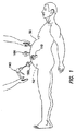
図1及び図2を参照すると、複数のトロカール100が体壁50、例えば腹壁を貫通し、体腔52、例えば腹腔内に配置された代表的な腹腔鏡下外科的処置又は手技が示されている。体壁50を膨らませて腹腔鏡下手技のための作業空間を提供するよう体腔52内にはガスが送気され又は体腔52はガスでインフレートされている。トロカール100は各々、カニューレ110及びシール150を有している。正圧がカニューレ110と関連したシール150によって体腔52内に維持されている。加うるに、カニューレ110は、隣接の組織に対してガス密シールを形成しなければならない。正圧がカニューレ110と関連したシール150かカニューレと隣接の組織との間のシールかのいずれから失われた場合、手技が損なわれる場合がある。
Referring to FIGS. 1 and 2, a representative laparoscopic surgical procedure or procedure is shown in which a plurality of
体腔52をインフレートさせると、体壁50が大幅に膨らまされる場合がある。接近部位は、体壁50の膨隆下で拡大してカニューレ110の位置決め及び密封具合を損ねがちな場合がある。上述したように、トロカール100を介して用いられた器械190の操作の結果として、カニューレ110が体壁50を通って接近部位内において近位側の方向か遠位側の方向かのいずれかに動く場合がある。これが起こると、或る程度の液状化が起こる場合があり、カニューレ110と体組織との間の好ましい関係が損なわれる場合がある。
When the
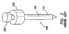
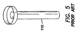
次に図3〜図6を参照すると、カニューレ110、シールハウジング150及び栓子160を有する代表的な組み立て状態のトロカール100が示されている。カニューレ110は、体壁50を通ってこれを容易に挿入することができるよう滑らかな外面102を有している。シールハウジング150は、逆行性ガス流を阻止するシールシステムを収容している。栓子160は、カニューレ110を通す経路を体壁50を貫通して作る切断又は穿通器械である。外科用栓子160は、一般に、関連のカニューレ110に適した欠損部を組織に作るような寸法形状のものである。しかしながら、欠損部は、トロカール100又はカニューレ110を操作しているときの手術手技中、拡大する傾向をもつ場合がある。器械190を遠位側に押したり近位側に押したりし又は挿入したり引き抜いたりしているときに、カニューレ110は、器械190とトロカールハウジングのシール150との間の摩擦に起因して動く場合があり又は偶発的に抜ける場合がある。
3-6, a representative assembled
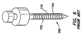
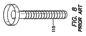
特に図6〜図8を参照すると、カニューレ110の外面102が複数の隆起特徴部115を有するトロカール100又は接近器具が示されている。これら隆起特徴部115は、トロカール100を介して器械190を操作しているとき、特に検体を取り出しているときに近位側への運動及び遠位側への運動に対する抵抗を増大させるような寸法形状のものである。先行技術は、順次隆起したリング又は隆起した並目ねじ115を有している。先行技術のリング又はねじ山115は、カニューレ110を或る程度まで安定化することができるが、これらリング又はねじ山は、必ずしも、カニューレ110を体壁50の隣接の組織に密着させるわけではない。これらシステムの使用と関連してガスの損失が生じる場合がある。隆起リング又はねじ山115は又、体壁50を貫通するのに必要な挿入力を増大させる。挿入力は、連続して位置した別々の隆起リング又は特徴部と比較して、連続並目ねじ115の場合に減少する場合がある。というのは、ねじ山付きカニューレ110は、実際には、適当な回転なしに押し通すのではなく、ねじ山方向及びピッチに従って組織欠損部中に「ねじ込まれる」からである。
With particular reference to FIGS. 6-8, a
図9〜図12を参照すると、先行技術の外科用接近器具100が、カニューレ110を有し、このカニューレは、その遠位端部側部分122と関連したインフレート可能なバルーン120を有している。バルーン120は、未インフレート状態においてカニューレ110にぴったりと嵌まるような寸法形状のものである。カニューレ110を体壁50を貫通して体腔52内に正しく配置した後バルーン120をインフレートさせる。バルーン120は、一般に、滑り反力部材、例えばフォームボルスタ180と関連している反力によって体壁50の内面54に当てて保持される。ボルスタ180は、カニューレ110の近位部分と関連している。先行技術の器具と関連したバルーン120は、代表的には、カニューレ110の一部として構成された「厚肉(厚壁)」構造体である。バルーン120は、一般に、カニューレ110の遠位端部側部分122に結合され、インフレーションチャネル又はルーメンがカニューレ110の壁内に設けられる。
Referring to FIGS. 9-12, a prior art
図13を参照すると、前進させた固定特徴部を含むトロカールカニューレ組立体210の実施形態が示されている。トロカールカニューレ組立体210は、シールハウジング212と、スリーブ組立部品(サブアセンブリ)214とを含むのが良く、スリーブ組立部品214は、トロカールカニューレ216、インフレート可能なバルーン220を含むスリーブ218、保持ディスク222、及び先端部プロテクタ224又は状態調節補助具を含む。トロカールカニューレ組立体の或る特定の実施形態に関し本明細書において説明する種々の観点をバルーンカニューレ又は保持カニューレのいずれにも用いることができる。
Referring to FIG. 13, an embodiment of a
引き続き図13を参照すると、シールハウジング212又は弁ハウジングは、器械用シール及びゼロシールを有するのが良い。幾つかの実施形態では、弁ハウジングは、カニューレ216に取り外し可能に結合されるのが良く、一実施形態では、この弁ハウジングは、送気用ガスを体腔、例えば腹腔内に供給する入口を有する。種々の実施形態において弁ハウジング内に納められた器械用シール及びゼロシールは、別々のものであっても良く一体形シールであっても良い。ゼロシール及び器械用シールは、弁ハウジングを通ってカニューレ216のルーメン236(図14)内に至る器械用経路を封止することができる。他の実施形態では、トロカールカニューレ216は、別個の弁ハウジングが設けられていない状態でトロカールカニューレ内に直接位置決めされた器械用シール及びゼロシール(別々又は一体形シール)を有しても良く、封止された器械用チャネル経路を備えたトロカールカニューレは、近位端から遠位端までの比較的短い長さを有し、それにより高さの低いプロフィールが定められる。
With continued reference to FIG. 13, the
或る特定の実施形態では、トロカールカニューレ組立体210は、標準サイズを有する外科用器械、例えば腹腔鏡的手術用ツールを受け入れるよう寸法決めされているのが良い。例えば、トロカール組立体210は、最大5mm外科用ツール製品種目に合わせて寸法決めされた外科用ツールを受け入れるよう寸法決めされる共に形作られた「5mmトロカールカニューレ」であるのが良い。他の実施形態では、トロカール組立体210は、11mm又は12mm外科用ツール製品種目とそれぞれ同じほど大きく寸法決めされた外科用ツールを受け入れるよう寸法決めされると共に形作られた「11mmトロカールカニューレ」又は「12mmトロカールカニューレ」であるのが良い。幾つかの実施形態では、トロカールカニューレ組立体210は、トロカールカニューレ組立体210、シールハウジング212、及びシールハウジング212及びカニューレ組立体210を通って挿入可能な栓子を含むキットに含まれるのが良い。
In certain embodiments, the
図13及び図14を参照すると、トロカールカニューレ216は、流体入口ポート226を有するのが良い。流体入口ポート226は、流体源、例えば注射器又はシリンジを受け入れるようになっている。流体は、空気、別のガス、例えば二酸化炭素、ガス混合物又は液体、例えば水、食塩水、若しくは別の溶液を含むのが良い。さらに本明細書において説明するように、流体入口ポート226は、流体入口ポート226への流体の追加によりバルーン220がインフレートされるようスリーブ218に流体結合されている。
Referring to FIGS. 13 and 14, the
幾つかの実施形態では、流体入口ポート226は、一方弁、例えばポペット弁又は逆止弁228を有するのが良い。流体が逆止弁228を通って流体入口ポート226にいったん追加されると、逆止弁228は、この流体をトロカールカニューレ組立体210のスリーブ218及びバルーン220内に維持する。逆止弁228は、バルーン220をデフレートさせることが望ましい場合、この流体が例えば注射器によって逃げ出ることができ又はこの流体を抜き取ることができるよう選択的に開かれるのが良い。
In some embodiments, the
トロカールカニューレ
図15を参照すると、幾つかの実施形態では、トロカールカニューレ216は、近位端230、遠位端232、及び近位端230から遠位端232まで長手方向軸線Lに沿って延びるルーメン236を有する。ルーメン236は、外科用器械、例えば腹腔鏡的外科用ツールを受け入れるよう構成されている。
Trocar Cannula Referring to FIG. 15, in some embodiments, the
引き続き図15を参照すると、幾つかの実施形態では、トロカールカニューレ216は、近位端230のところに設けられたシールハウジングインターフェース238、シールハウジングインターフェース238の遠位側に設けられた流体入口ポート226、流体入口ポート226から遠位側に延びる全体として管状のカニューレ本体240、カニューレ216の遠位端232に隣接したところでカニューレ本体240に設けられた環状凹部、例えば環状溝242、及び遠位先端部244を有する。シールハウジングインターフェース238は、シールハウジングに密着するシール、例えばOリング246(図14)を有するのが良い。
With continued reference to FIG. 15, in some embodiments, the
図示の実施形態では、流体入口ポート226は、流体入口250及び流体ドーム252を有する。流体入口250は、インフレーション流体源を受け入れるよう構成され、この入口ポート内には逆止弁228が設けられるのが良い(図14)。
In the illustrated embodiment, the
図示のように、流体入口ポート226の流体ドーム252は、流体入口250に流体結合されている。幾つかの実施形態では、流体入口ポート226は、全体として滑らかな外面254を有するのが良い。滑らかな外面254により、接着剤がスリーブ218の下に流れて比較的強固なバルーンとカニューレの結合部を得ることができる。幾つかの実施形態では、流体入口ポート226は、湾曲したプロフィール、例えば全体として涙滴の形状を呈するよう形作られるのが良く、流体ドーム252は、バルーンインフレーション/デフレーションのための流体経路が塞がった状態になる恐れを減少させるよう湾曲したプロフィールを有するのが良い。他の実施形態では、流体入口ポート226は、別の湾曲したプロフィール、例えば全体として円筒形、全体として楕円形、又は全体として長円形のプロフィールを有するのが良い。他の実施形態では、流体入口ポート226は、別の曲線状のプロフィールを有するのが良い。
As shown, the
カニューレ本体
引き続き図15を参照すると、幾つかの実施形態では、カニューレ本体240は、流体入口ポート226からカニューレ216の遠位端232まで遠位側に延びている。カニューレ本体240は、外面260及び第1の外径D1を有する。幾つかの実施形態では、カニューレ本体240の外面260は、この上へのスリーブ218の取り付けを容易にするよう構成されているのが良い。例えば、カニューレ本体240の外面260は、カニューレ本体240上でのこれに沿うスリーブ218の摺動前進を容易にするよう比較的軽度の模様付き表面仕上げを有するのが良い。
Cannula Body With continued reference to FIG. 15, in some embodiments, the
幾つかの実施形態では、カニューレ本体240は、流体入口ポート226からカニューレ216の遠位端232まで全体として長手方向に延びる1本又は2本以上の流体チャネル262又は溝を有するのが良い。流体チャネル262は、カニューレ本体240の画面260に形成されるのが良く、この流体チャネルは、カニューレ本体240中に深さdにわたって延びるのが良い。図示のように、流体チャネル262は、流体入口ポート226に流体結合されており、この流体チャネルは、スリーブ218のバルーン220に隣接した或る箇所まで遠位側に延びている(図14)。かくして、流体チャネル262は、バルーン220のインフレーション及びデフレーションのための流体通路の実現を可能にするようバルーン220と関連して働くことができる。有利には、流体チャネル262がカニューレ本体240内に埋め込まれた状態で、スリーブ組立部品214は、比較的小さな外径及び低プロフィールを有することができる。望ましくは、比較的小さな直径及び低プロフィールにより、カニューレ組立体210は、比較的小さな挿入力を示すことができる。同様に、バルーン220と流体チャネル262の幾何学的形状により、バルーン220がデフレーション中、流体流路を塞ぐ事態の発生を減少させることができる。
In some embodiments, the
引き続き図15を参照すると、カニューレ本体240は、トロカールカニューレ216の遠位端に隣接したところに環状凹部、例えば環状溝242を有するのが良い。幾つかの実施形態では、環状溝242は、トロカールカニューレ216の長手方向軸線Lに全体として垂直な向きをなしてカニューレ本体240に形成されている。他の実施形態では、他の向きをなした環状溝242を形成することができる。或る特定の実施形態では、図示のように、環状凹部は、トロカールカニューレ216の遠位端に隣接したところでトロカールカニューレ216の長手方向軸線Lに沿って比較的短い距離にわたって延びる凹み表面を備えた環状溝242を有する。他の実施形態では、環状凹部又は環状溝は、遠位端に隣接して位置する或る場所から近位側にトロカールカニューレ216の近位端又は遠位端との間に位置する或る場所まで又はトロカールカニューレ216の近位端に隣接して位置する或る場所まで延びる凹み面を有するのが良い。
With continued reference to FIG. 15, the
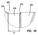
図16は、環状溝242の一実施形態の切除詳細図である。幾つかの実施形態では、環状溝242は、近位縁270、遠位縁272、及び近位縁270と遠位縁272との間に位置する環状インターフェース表面274を有するのが良い。環状インターフェース表面274は、カニューレ本体240の第1の外径D1よりも小さい第2の外径D2を有するのが良い。近位縁270は、カニューレ本体240の第1の外径部D1と環状インターフェース表面274の第2の外径部D2との間に延びる全体として段付きの縁を有するのが良い。望ましくは、段付き縁は、インフレート形態にあるバルーン220内に流体を維持するようカニューレ本体240に対するスリーブ218の封止性能を高めることができる。
FIG. 16 is a detailed cutaway view of one embodiment of the
引き続き図16を参照すると、幾つかの実施形態では、環状溝242の遠位縁272は、傾斜した縁を有するのが良い。傾斜縁は、環状インターフェース表面274に対して横方向の角度をなして延びるのが良い。他の実施形態では、環状溝242の遠位縁272は、全体として段付きの縁又は別の幾何学的プロフィール、例えばアール付き(丸みのある)曲線状の縁を有する縁から成るのが良い。
With continued reference to FIG. 16, in some embodiments, the
図15を参照すると、幾つかの実施形態では、カニューレ216の遠位端232のところの遠位先端部244は、カニューレ216の長手方向軸線Lに垂直な平面に対して角度θをなして延びる遠位縁278を有する。角度θは、約5°〜約45°であるのが良い。5mmサイズのカニューレ組立体210の幾つかの実施形態では、遠位先端部244の遠位縁278は、長手方向軸線Lに垂直な平面に対して約17°の角度をなして傾けられているのが良い。他のサイズ、例えば11mm及び12mmカニューレを含むカニューレ組立体210の実施形態では、この角度は、相関関係をなすカニューレ216にマッチするよう僅かに異なるのが良い。例えば、11mmカニューレ組立体の幾つかの実施形態では、角度θは、約20°であるのが良く、12mmカニューレ組立体の幾つかの実施形態では、この角度θは、約12°であるのが良い。カニューレ組立体210の他の実施形態に関し、他の角度を用いることができる。
Referring to FIG. 15, in some embodiments, the
有利には、傾斜した遠位先端部244は、カニューレの長手方向軸線に垂直な遠位縁を備えた真っ直ぐな先端部から成る遠位先端部と比較して、カニューレ組立体210を体壁、例えば患者の腹壁中に挿入するのに必要な力を大幅に減少させることができる。真っ直ぐな先端部を有するバルーントロカールは、主として、カットダウン技術を用いて体壁を通り、比較的大きな切開創を通って手術部位中に導入される。望ましくは、傾斜遠位先端部244は、種々の切開創長さを有する種々のカニューレ挿入技術を含む外科的処置において固定用カニューレの使用を容易にすることができる。例えば、傾斜遠位先端部を備えた固定用トロカールは、ブレード付き、ブレードなしの光学的、又はガス注入栓子を用いた挿入技術を含む挿入技術によって比較的小さい挿入力で挿入できる。
Advantageously, the angled
幾つかの実施形態では、カニューレ本体240は、ポリカーボネート材料で作られるのが良い。望ましくは、この材料の硬度及び相対的剛性により、カニューレ216は、可撓性スリーブ218及びバルーン220を取り付けるための支持用管として且つ栓子又は他の医療器械を挿入するためのポートとしての役目を果たすことができる。他の実施形態では、カニューレ本体240は、他の材料、例えばポリエステル材料から成るのが良い。
In some embodiments, the
スリーブ
或る特定の実施形態では、スリーブがトロカールカニューレの近位端に隣接したところからトロカールカニューレ遠位端に隣接したところまで延びている。スリーブは、近位端及び遠位端を有し、この遠位端に隣接してインフレート可能なセグメントが設けられている。スリーブは、スリーブの遠位端及びスリーブの近位端のところでトロカールカニューレに結合されるのが良い。
Sleeve In certain embodiments, the sleeve extends from adjacent the proximal end of the trocar cannula to adjacent the distal end of the trocar cannula. The sleeve has a proximal end and a distal end, and an inflatable segment is provided adjacent to the distal end. The sleeve may be coupled to the trocar cannula at the distal end of the sleeve and the proximal end of the sleeve.
スリーブは、結合時に直径方向において比較的低いプロフィールを作る技術によってトロカールカニューレに結合されるのが良く、このスリーブは、望ましい封止性能を有し、しかも、効率的に製造可能である。例えば、幾つかの実施形態では、トロカールカニューレは、実質的に滑らかな連続した外面を有するのが良く、スリーブは、化学的結合部を形成するための接着剤の塗布によってこの滑らかな表面に結合されるのが良い。他の実施形態では、スリーブは、融着結合領域を形成するための熱溶接又はUV溶接によってトロカールカニューレに結合されるのが良い。幾つかの実施形態では、図17〜図19を参照して更に説明するように、スリーブは、外面の非連続領域のところで、例えば、外面に形成された1つ又は2つ以上の環状溝のところでトロカールカニューレに結合されるのが良い。幾つかの実施形態では、互いに異なる結合技術を遠位端のところで用いるのではなく、スリーブの近位端のところで用いるのが良く、他方、他の実施形態では、実質的にほぼ同じ結合技術をスリーブの近位端と遠位端のところに用いることができる。 The sleeve may be coupled to the trocar cannula by a technique that creates a relatively low profile in the diametrical direction upon coupling, which sleeve has the desired sealing performance and can be efficiently manufactured. For example, in some embodiments, the trocar cannula can have a substantially smooth continuous outer surface and the sleeve can be bonded to this smooth surface by application of an adhesive to form a chemical bond. It is good to be done. In other embodiments, the sleeve may be coupled to the trocar cannula by thermal welding or UV welding to form a fusion bonded region. In some embodiments, as further described with reference to FIGS. 17-19, the sleeve is formed at a discontinuous region of the outer surface, eg, one or more annular grooves formed on the outer surface. By the way, it may be connected to the trocar cannula. In some embodiments, different coupling techniques may be used at the proximal end of the sleeve rather than at the distal end, while in other embodiments substantially the same coupling technique is used. It can be used at the proximal and distal ends of the sleeve.
図18を参照すると、スリーブ218及びカニューレ組立体210の実施形態が示されている。図示の実施形態では、スリーブ218は、近位端281のところに設けられた近位インターフェース区分280又はカップラ、カップラから遠位側に延びる細長い管状本体282、細長い管状本体282の遠位側に位置決めされたバルーン220、及びバルーンの遠位側に位置した結合セグメント284を有する。
Referring to FIG. 18, an embodiment of a
幾つかの実施形態では、スリーブ218は、例えばストレッチ吹込み成形によって一体的単体的に形成されるのが良い。有利には、ストレッチ吹込み成形法は、バルーン材料、厚さ及び形状の高度の制御を可能にする。
In some embodiments, the
スリーブ218は、ポリオレフィン材料、例えば通常熱収縮管材としてのポリオレフィン材料から成るのが良い。或る特定の実施形態では、SumitomoA2クリアーポリオレフィン管材を用いるのが良い。有利には、ポリオレフィン材料から成るスリーブ218は、ラテックス又はシリコーンゴム材料と異なり、ラテックスがなく、非孔質であり且つノンフラグメンティング(non-fragmenting )である。望ましくは、ポリオレフィン管材は、軟質且つ可撓性であるのが良く、高度の架橋性を有するのが良く、その結果、このポリオレフィン管材は、他の試験対象の材料と比較して、材料厚さが所与の場合、比較的高い強度を有する。ポリオレフィンスリーブ218を含むカニューレ組立体210の実施形態では、信じられないほど薄いバルーン区分を有しているにもかかわらず、バルーン220は、代表的には、設計インフレーション圧力の平均5倍の圧力であっても破断なく過剰インフレート可能である。また、ポリオレフィン材料の軟らかさと可撓性により、ユーザにとっての器具の手触りが向上する一方で、挿入力も又減少する。他の実施形態では、スリーブは、他の材料、例えばシリコーン材料、シルラン、ポリイソプレン、ポリウレタン材料、ポリウレタンブレンド、TYGON (登録商標)、VITON (登録商標)、SANTOPRENE(登録商標)、MYLAR (登録商標)、又は別の適当なポリマー材料から成っていても良い。
The
図示の実施形態では、カニューレ組立体は、カニューレ216上の遠位側の場所に位置決めされた1つのバルーン220を含む。種々の他の実施形態では、患者の腹壁厚さ及び解剖学的構造のばらつきを考慮に入れて追加のバルーンを設けるのが良い。また、互いに異なる場所に設けられたバルーンは、互いに異なる材料を用いていることができる。バルーンは、膨張性であっても良く非膨張性であっても良く又はこれら両方の組み合わせであっても良い。バルーン220は、一実施形態では、ドーナツ形状であり又は一観点では、円盤状である。バルーン220の寸法及び/又は配置場所は、トロカールをカニューレ216の所望の保持を患者の体に合わせて変化させるよう様々であって良い。
In the illustrated embodiment, the cannula assembly includes a
引き続き図18を参照すると、カップラ280は、カニューレ216に係合するよう寸法決めされると共に形作られている。例えば、図示の実施形態では、カップラ280は、カニューレ216の流体ドーム252の涙滴形状にマッチするよう変身した又は全体として涙滴形状の湾曲したプロフィールを有する。有利には、この合致したプロフィールにより、スリーブをカニューレ216に取り付けたときに締り嵌めを可能にすることができ、それによりこれら相互間の漏れの恐れが減少する。
With continued reference to FIG. 18, the
幾つかの実施形態では、近位端281のところのカップラの外面には、模様が付けられている。この粗い表面は、スリーブ218の接着剤の結合を容易にし、それによりスリーブ218は、バルーン220を完全にインフレートさせたときにカニューレ216から分離されるのが阻止される。例えば、粗加工された又は模様付きの表面は、複数本の比較的小さなチャネルを作ることができ、これらチャネルは、スリーブ218とカニューレ216の強固な接着剤結合部を作るようウィッキング又は毛管作用プロセスを介して化学的接着剤の流れを高める。望ましくは、カップラのところの模様付き又は粗加工表面により、スリーブ218は、もしそのようにしていなければ接着剤と結合するのが困難な場合のある材料から成ることが可能である。
In some embodiments, the outer surface of the coupler at the proximal end 281 is patterned. This rough surface facilitates bonding of the
引き続き図18を参照すると、スリーブ218の細長い管状本体282又はシャフトは、カップラ280から遠位側に延びている。このシャフトは、一様であり且つ薄壁のものであるが、保持ディスク222又は他のボルスタの摺動運動に耐えるに足るほど厚い。
With continued reference to FIG. 18, the elongated
図19は、スリーブ218がカニューレ216上に位置決めされたカニューレ組立体210の遠位端を示している。有利には、ストレッチ吹込み成形法によって形成されたスリーブ218が細長い管状本体282の厚さt1の制御を高めることができ、それによりトロカールカニューレ組立体210の外径が最小限に抑えられ、その結果患者にとって小さな切開創サイズが得られる。幾つかの実施形態では、細長い管状本体282は、約0.008インチ(0.2032mm)〜約0.012インチ(0.3048mm)の厚さt1を有するのが良い。
FIG. 19 shows the distal end of
引き続き図19を参照すると、図示のように、スリーブ218は、細長い管状本体282の遠位側に位置した非膨張性のインフレート可能なバルーン220を有している。バルーン220は、細長い管状本体282の厚さt1よりも小さい厚さt2を有するのが良い。有利には、ポリオレフィン材料をストレッチ吹込み成形してバルーン220を形成することにより、比較的小さな厚さの高強度材料が得られる。幾つかの実施形態では、バルーンは、約0.0005インチ(0.0127mm)〜0.002インチ(0.0508mm)の厚さを有するのが良い。或る特定の実施形態では、バルーンは、約0.0015インチ(0.0381mm)の厚さを有するのが良い。
With continued reference to FIG. 19, as shown, the
有利には、バルーン/シャフトインターフェースのところの急激な厚さの移行(変化)をストレッチ吹込み成形法により著しく軽減させ又はなくすことができる。望ましくは、ストレッチ吹込み成形法のバルーン厚さにおける比較的高度の制御は、カニューレ組立体の遠位端部に隣接したところの外径を最小限にするのにも寄与することができ、その結果、挿入力が減少する。 Advantageously, the abrupt thickness transition at the balloon / shaft interface can be significantly reduced or eliminated by the stretch blow molding process. Desirably, a relatively high degree of control in the balloon thickness of the stretch blow molding process can also contribute to minimizing the outer diameter adjacent to the distal end of the cannula assembly. As a result, the insertion force is reduced.
図17を参照すると、スリーブ218は、その遠位端のところに面取り先導縁部298を有するのが良い。望ましくは、結合セグメント284の長手方向軸線に対する面取り先導縁部298の角度は、カニューレの遠位端とスリーブの遠位端との間に滑らかな移行部をもたらすよう選択されるのが良い。結合セグメント284が環状溝242内に位置決めされた状態で、結合セグメントの長手方向軸線は、カニューレの長手方向軸線に実質的に平行である。かかる滑らかな移行は、遠位端のところに全体として角のあるコーナー部を有するトロカールカニューレ組立体と比較して、トロカールカニューレ組立体にとっての挿入力の減少に寄与することができる。幾つかの実施形態では、面取り先導縁部298の角度は、結合セグメント284の長手方向軸線に対して約50°〜約65°であるのが良い。
Referring to FIG. 17, the
図17及び図19は、スリーブ218がカニューレ216上に位置決めされたカニューレ組立体210の遠位端の切除詳細図である。幾つかの実施形態では、スリーブ218の遠位端283のところの結合セグメント284の外面288は、模様付きであり、それにより接着剤を保持することによるスリーブ218の接着剤の結合を助けると共に毛管作用プロセスによる接着剤のウィッキングによってスリーブとカニューレとの間における接着剤の流れを促進するための粗い結合面が得られる。幾つかの実施形態では、環状溝242の環状インターフェース表面274は、カニューレへのスリーブの結合を助けるために模様付きであり、例えば、小さなピット、溝又は粗い表面を備えている。幾つかの実施形態では、シアノアクリレート系瞬間接着剤とUV硬化接着剤の組み合わせが結合セグメント284を環状溝242に結合するスリーブ‐カニューレ結合部に使用することができる。他の実施形態では、他の接着剤、例えばシアノアクリレート系接着剤のみ若しくはUV硬化接着剤のみ又は別のタイプの接着剤を用いることができる。望ましくは、接着剤を実質的に環状溝242内に塗布するのが良く、その結果、カニューレ216の遠位端232がスリーブ218とカニューレ216との間に滑らかで低プロフィールの移行部を有することができるようにする。有利には、スリーブ218とカニューレ216との間の低プロフィール移行部は、カニューレ組立体210を手術部位内に位置決めするのに必要な沿う入力を減少させることができる。
17 and 19 are detailed cutaway views of the distal end of
幾つかの実施形態では、接着剤290を主としてカニューレ本体240の環状溝242内に配置することによって低プロフィール移行を一層高めることができる。スリーブ218の結合セグメント284及びカニューレ216の環状溝242は、接着剤290を主として環状溝242内に配置するのを助けるような寸法形状のものであるのが良い。例えば、幾つかの実施形態では、環状溝の環状面は、カニューレの長手方向軸線に沿って第1の長さl1を有し、結合セグメントは、カニューレの長手方向軸線に沿って第2の長さl2を有し、第2の長さは、第1の長さよりも短い。かくして、幾つかの実施形態では、環状溝242の環状インターフェース表面274は、係合セグメント291及び露出セグメント293を有するのが良い。係合セグメント291は、第2の長さl2で定められると共に結合セグメント284と係合するのが良い。露出セグメント293は、第1の長さl1と第2の長さl2の差によって定められるのが良い。露出セグメント293は、望ましくは、スリーブ218の結合セグメント284を環状溝242に対して維持するよう接着剤のビードを配置するのに十分な表面を提供するよう寸法決めされるのが良い。かくして、幾つかの実施形態では、接着剤290が結合セグメント284を環状溝242に結合するよう環状インターフェース表面274の露出セグメント293に少なくとも部分的に塗布されるのが良い。
In some embodiments, the low profile transition can be further enhanced by placing the adhesive 290 primarily within the
幾つかの実施形態では、スリーブ218は、環状溝242への結合セグメント284の接着に類似したシアノアクリレート系瞬間接着剤とUV硬化接着剤の組み合わせにより近位インターフェース表面280又はカップラのところでカニューレ216に接着されるのが良い。他の実施形態では、他の接着剤、例えばシアノアクリレート系接着剤のみ若しくはUV硬化接着剤のみ又は別のタイプの接着剤を用いることができる。
In some embodiments, the
保持ディスク
図21及び図22は、カニューレ組立体210上に位置決め可能な保持ディスク222を示している。幾つかの実施形態では、カニューレ組立体210は、スリーブ218の細長い管状本体282周りでバルーン220の近位側に位置決めされた近位固定部材、例えば保持ディスク222を含む。トロカールカニューレ組立体210を体壁を通って手術部位のところに挿入した後、バルーン220をインフレートさせてトロカールカニューレ組立体210の位置を手術部位内に維持するのが良く、近位固定部材又は保持ディスク222は、トロカールカニューレ216が手術部位中へ一層前進するのを阻止することができる。
Retaining Disk FIGS. 21 and 22 show a
図22に示されているように、保持ディスク222は、保持ディスク222を通る通路294を定める中央穴292を備えた全体として円形のディスクから成るのが良い。中心穴292の通路294は、内周部にリブ付きプロフィールを有するのが良い。リブ付きプロフィールは、複数個の環状溝296を含むのが良い。リブ付きプロフィールは、スリーブ218の細長い管状本体282の外面に摩擦係合するのが良く、その結果、保持ディスク222は、スリーブ218に沿って手動で摺動可能であるが、選択された位置に留まりがちである。
As shown in FIG. 22, the
幾つかの実施形態では、保持ディスク222は、弾性ポリマー材料、例えばKRATON(登録商標)材料で作られるのが良い。KRATON(登録商標)材料で作られた保持ディスク222は、スリーブ218の外面との所望レベルの摩擦係合をもたらすことができ、しかも、トロカールカニューレのユーザにとって人間工学的に心地よい軟質の且つ柔軟性のある感触を提供することができる。有利には、保持ディスク222の丸形コーナー部及び軟質材料は、トロカールを定位置に保持するための無外傷性手段となる。幾つかの実施形態では、保持ディスク222を射出成形法により形成することができる。有利には、単一の成形保持ディスク222を有するトロカールカニューレの実施形態は、製造上及び組立て上の効率を有することができ、しかも多数の組立て状態のコンポーネントを含むクランプ機構体に関して使いやすさを高めることができる。
In some embodiments, the
幾つかの実施形態では、トロカールカニューレ組立体210は、トロカールカニューレ216が手術部位中へ一層前進するのを阻止するためにカニューレ本体240に沿う近位側への保持ディスク222の運動に抵抗するよう構成されているのが良い。例えば、カニューレ本体240の外面260は、これがカニューレ本体の近位端のところの外径に対して遠位端のところのこれよりも小さな外径を有するよう僅かなテーパを有するのが良い。かくして、保持ディスク222とスリーブ218との摩擦係合により生じる摩擦力は、保持ディスク222をトロカールカニューレ216に沿って近位側に摺動させているときに増大することができる。保持ディスク222は、トロカールカニューレ216を体壁に対して固定するために使用できる。締まり嵌め、リブ付きプロフィール、及びテーパ付きカニューレ216は、器械がカニューレ216内に挿入されるときに保持ディスク222がカニューレ本体240に沿って前進するのを阻止する。
In some embodiments, the
幾つかの実施形態では、弾性ポリマー材料から成る保持ディスク222は、張力下で貯蔵されると、クリープを呈する場合がある。有利には、カニューレ本体240の外面260が僅かなテーパを有する場合、使用前に、保持ディスク222は、保持ディスク222のクリープの発生を減少させるために用いられていないとき、比較的小さな外径を有する遠位端に隣接して位置決めされるのが良い。使用中、保持ディスク222をカニューレ216のシャフトに沿って上方に大きなカニューレ直径の領域まで近位側に前進させ、それによりディスク222の配置及び固定を可能にする。加うるに、かかるテーパ付きカニューレ本体240は、カニューレ本体240の製造性において別の利点を有する場合がある。例えば、かかるテーパ付きプロフィールは、カニューレ本体240が射出成形法で作られる実施形態では、金型からのカニューレ本体240の取り出しを容易にすることができる。
In some embodiments, the
他の実施形態では、カニューレ組立体210は、クランプ機構体を備えたボルスタ222′、例えば全体として円筒形又は円錐形の安定化部材を含むのが良い。例えば、幾つかの実施形態では、カニューレ組立体210は、オキヒサ等(Okihisa et al.)に付与された米国特許第8,162,893号明細書(発明の名称:TOROCAR STABILITY ASSEMBLY)に記載された種々のクランプ機構体のうちの1つを含む安定化組立体を含むのが良い。なお、この米国特許を参照により引用し、その記載内容全体を本明細書の一部とする。
In other embodiments, the
状態調節補助具及びバルーン折り畳み
図20を参照すると、幾つかの実施形態では、トロカール組立体210は、バルーン220を本体240に対して収縮させると共にバルーン220を輸送中保護するための状態調節補助具224を含むのが良い。さらに、所要の挿入力がバルーン220のところのトロカールカニューレ組立体210の全体的外径と比例して変化することが観察できる。かくして、使用前において、小さな直径を有すると共にカニューレ216の遠位先端部244からバルーン220までの比較的に滑らかな移行部を有する挿入形態にバルーン220を折り畳むことによって挿入力を減少させることが望ましい場合がある。
Conditioning Aid and Balloon Folding Referring to FIG. 20, in some embodiments, the
デフレート状態の又は挿入形態にある非弾性又は非膨張性バルーン220は、カニューレ本体240の外面260に自動的に同形化するわけではない。幾つかの実施形態では、バルーン材料は、皺になり、折り目及び/又はひだを形成する傾向を有する場合があり、しかも種々の箇所でカニューレ本体240の外面260から遠ざかって突き出る場合がある。非インフレート状態のバルーンが備える場合のある凸凹は、体壁を通る非インフレート状態の保持バルーン220の挿入中に抵抗をもたらす場合がある。バルーン220を挿入状態に折り畳むことにより、挿入に必要な力を減少させることができる。幾つかの実施形態では、挿入形態では、バルーン220は、カニューレ本体240に沿ってカニューレ216の近位端230に向かって折り畳まれる。バルーン220を近位端230に向かって折り畳むことにより、その結果として、挿入形態においてバルーン220に1つ又は2つ以上の折り目が作られる場合がある。例えば、幾つかの実施形態では、バルーン220を一段法で近位側に折り畳むことができ、他の実施形態では、バルーン220を当初、最初の折り畳みで遠位側に折り畳むのが良く、次に、第2の折り畳みで近位側に折り畳むのが良い。バルーン220をトロカール配置方向とは逆に折り畳むことによって、バルーンは、挿入力を減少させると共にバルーン直径方向プロフィールを低くするのを助ける。状態調節補助具224は、バルーン220を手術部位への挿入のためにトロカールカニューレ組立体210から取り外すまで、バルーン220を挿入形態に維持することができる。さらに、状態調節補助具224は、カニューレ組立体210のバルーン220及び/又は遠位先端部244を輸送中又は手術の際の使用に先立って、損傷しないよう保護することができる。
A non-elastic or
有利には、トロカールカニューレ組立体は、状態調節補助具224がバルーン220上でこれに沿って送り進められてバルーンが成形可能な状態にあるときにバルーン220をカニューレ本体240に対して収縮させる場合、減少した直径及び比較的小さい挿入力を達成することができる。例えば、図29及び図30を参照して以下に更に説明するように、ストレッチ吹込み成形バルーンにより、状態調節補助具224をこのバルーンが残留熱を保持しているとき、バルーン220上でこれに沿って前進させるのが良い。成形可能な状態を持続する時間は、用いられる材料及びバルーン220の厚さに基づいて様々な場合がある。したがって、バルーン材料の温度及び/又はバルーンの成形からの経過時間をモニタしてバルーン220が成形可能な状態にあるときに状態調節補助具224の利用を保証することが望ましい場合がある。かくして、状態調節補助具224は、成形されたバルーン220が冷えているときにこのバルーン220を収縮させてカニューレに締着させるのが良い。有利には、バルーン220が成形可能な状態にある間にバルーン220を収縮させてこれをカニューレ本体に締着させて、同等のあらかじめ成形されたバルーンを折り畳んでこれをカニューレ本体に取り付けるやり方に対して、小さな外径を達成することができる。さらに、挿入力の一層の著しい減少は、バルーンが残留熱を保持している間であって状態調節補助具224をカニューレ本体上に位置決めする前にバルーン220を二段法(最初の遠位タック又は折り目の形成に続き、第2の遠位折り目を形成する)で折り畳んだ場合に観察できる。
Advantageously, the trocar cannula assembly is used when the
図20は、中空管状セグメントを有する状態調節補助具224を示している。図示の実施形態では、状態調節補助具224は、内径を備えた内面300を有する管材の一区分から成る。内面300の内径は、トロカールカニューレ組立体の折り畳みバルーン220上に滑り嵌めをもたらすよう寸法決めされている。図示の管状セグメント型状態調節補助具224は、望ましくは或る特定の製造上及び組立て上の効率をもたらすことができる比較的単純な構造のものである。他の実施形態では、状態調節補助具は、多くの形態、例えば、適当な内径の収縮管、キャップ、コーン又はコイルの形態を取ることができる。或る特定の実施形態では、状態調節補助具は、種々の材料で作ることができ、かかる材料としては、例えば、熱可塑性プラスチック、熱硬化性プラスチック、金属及びガラスが挙げられる。幾つかの実施形態では、状態調節補助具は、全体として円錐形であるのが良く又は使用に先立って取り外しを容易にするようテーパ付き内面を有するのが良い。望ましくは、状態調節補助具は、状態調節を最適化すると共にバルーンの損傷を阻止するよう滑らかな内面を有するのが良い。
FIG. 20 shows a
一実施形態では、状態調節補助具224は、バルーン220を越える状態調節補助具224の近位側への運動を阻止するよう構成されていることが望ましい場合がある。幾つかの実施形態では、状態調節補助具224は、状態調節補助具224が近位側に動いてバルーン220を越えるのを阻止するよう近位端のところの直径よりも遠位端のところの直径が幾分小さいよう形作られており、その目的は、状態調節補助具224をバルーン220に取り付けた状態に維持することにある。他の実施形態では、状態調節補助具224は、状態調節補助具224が近位側に動くのを阻止する戻り止め又は突出部を有するのが良い。幾つかの実施形態では、カニューレ組立体210は、保持ディスク222又はボルスタ222′と状態調節補助具224との間に設けられていて、状態調節補助具224がバルーン220を越えて近位側に動くのを阻止するスペーサを更に含むのが良い。保持ディスク222又はボルスタ222′は、一実施形態では、バルーン220の近くに位置決めされ、或いは、状態調節補助具224は、状態調節補助具224がバルーン220を越えて近位側に動くのを阻止するよう保持ディスク222又はボルスタ222′に接触するほど十分長い。状態調節補助具224がバルーン220を越えて近位側に動くのを阻止することにより、状態調節補助具224がバルーン220との接触関係を失い、それにより圧力を失ってバルーン220及び先端部244の保護を失うのが阻止される。
In one embodiment, it may be desirable for the
製造方法
図23〜図30は、本明細書において説明したトロカールの製造方法の種々の実施形態を示している。本明細書において説明したカニューレ組立体210の実施形態は、予備成形されたスリーブ218を含むのが良い。幾つかの実施形態では、カニューレ216を射出成形法により適当な材料、例えばポリカーボネート又はポリエステル材料で作るのが良い。
Manufacturing Method FIGS. 23-30 illustrate various embodiments of the trocar manufacturing method described herein. The embodiment of the
図29を参照すると、カニューレ組立体210を製作する方法が示されている。幾つかの実施形態では、ポリオレフィン熱収縮管のロールを区分又はブランクに切断し、次にこれを加熱してこの管を収縮させてカニューレ216よりも僅かに大きい取り付けサイズまで小さくする。次に、スリーブ218をカニューレ216に嵌めた状態で位置決めする(402)。僅かに大きめのスリーブ218をカニューレ216上にいったん取り付けると、スリーブ218を加熱して(416)、収縮させ、それによりカニューレ本体240の外面260に締着させるのが良い。例えば、スリーブの細長い管状本体282を取り付けのためにライン・ツー・ライン(line-to-line)で形成するのが良く、次に、僅かに加熱してこれを収縮させ、それによりカニューレ本体240の外面260に締着させるのが良い。スリーブ218をカニューレ216に嵌めた状態で位置決めする(402)。スリーブ218を前進させるのが良く、次に、スリーブ218の近位インターフェース区分280がカニューレ216の流体入口ポート226周りに位置決めされると共にスリーブ218の結合セグメント284が環状溝242内に位置決めされる(412)。
Referring to FIG. 29, a method of making
図29を参照すると、幾つかの実施形態では、スリーブがカニューレ216上にいったん位置決めする(402)と、スリーブ218を近位端281のところで切り落とし、次に遠位端283のところで切断し、それにより面取り先導縁部298を形成し又は作るのが良い。
Referring to FIG. 29, in some embodiments, once the sleeve is positioned 402 on the
図29を参照すると、予備成形スリーブ218をいったんカニューレ216上でこれに沿って前進させると共にスリーブ218の結合セグメント284をカニューレ216の環状溝242内に位置決めすると、スリーブ218をカニューレ216に連結し又は結合する(410)のが良い。例えば、幾つかの実施形態では、スリーブ218の近位端281及びスリーブ218の遠位端283を各々、カニューレ216に結合する(410)。幾つかの実施形態では、スリーブ218の近位インターフェース区分280をカニューレ216の近位端230に隣接して位置する場所に接着し、結合セグメント284を環状溝242に接着する。例えば、シアノアクリレート系接着剤及びUV硬化結合接着剤のうちの1つ又は2つ以上を用いてスリーブ218をカニューレ216に結合するのが良い。
Referring to FIG. 29, once the preformed
保持ディスク222をスリーブ218の外面周りでバルーン220の近位側に位置決めするのが良い。保持ディスク222をスリーブ組立部品214に取り付けると、取り付け具を用いてディスク222を僅かに拡張してこれをバルーン220上に取り付けると共に考えられるバルーン220の損傷を回避するのが良い。
The
引き続き図29を参照すると、いったんスリーブ218をカニューレに嵌めた状態で位置決めし(402)、そしてこれに結合する(410)と、次に、この組立部品を結合部位の近位側に位置する遠位端のところで局所的に加熱する(412)。加熱される材料の量は、直接バルーンの形成を開始させ、バルーンの壁厚を定める。壁厚の優れた制御は、バルーンに形成されるべき管の区分に熱を送り出す発熱体の適当な幅を選択することによって達成できる。例えば、幅が0.200インチ(5.08mm)である発熱体は、周囲壁厚が0.0015インチ(±0.0005インチ)のバルーンを首尾一貫して作る。他の実施形態では、異なるサイズの発熱体は、スリーブ218の遠位端を局所的に加熱して互いに異なる厚さのバルーンを形成することができる。
With continued reference to FIG. 29, once the
スリーブをいったん局所的に加熱する(412)と、インフレーション流体をスリーブ218に適用して、結合部の近位側でスリーブ218の遠位端に隣接してバルーンを形成する(418)。図23は、バルーン220の形成の仕方を概略的に示している。幾つかの実施形態では、バルーンは、全体として円形のディスク形状に形成されるのが良い。他の実施形態では、バルーンは、全体としてトロイド形又はドーナツ形のバルーンに形成されるのが良い。他の実施形態では、バルーン220は、他の形状、例えば全体として切頭円錐形プロフィール又は別の丸形プロフィールを有する状態で形成されるのが良い。有利には、バルーン形状のこの制御は、器具の全体的作業距離を最大にすることができる。さらに、丸形バルーン形状及び軟質材料は、トロカール組立体210を定位置に保持するための無外傷性手段となる。
Once the sleeve is locally heated (412), inflation fluid is applied to the
バルーンをいったん形成すると、バルーンを状態調節してバルーンを収縮させ、これをカニューレに締着させる(424)。例えば、図24に示されているように、バルーン220をスリーブ218の細長い管状本体282に沿ってカニューレ216の遠位端230に向かって挿入形態に折り畳むのが良い。上述したように、挿入力の著しい減少は、バルーンを二段法(バルーンが残留熱を保持している間、最初の遠位タック又は折り目の形成に続き、第2の遠位タック又は折り目を形成する)で折り畳んだ場合に観察できる。望ましくは、バルーンが局所化熱からの熱を保持しているときにバルーンを状態調節して(424)バルーンの収縮具合を高めるのが良い。図30に示されているように、幾つかの実施形態では、次に、状態調節補助具224をバルーン220上でこれに沿って前進させて(426)バルーン220を使用されるまで折り畳み状態に保ち、そしてカニューレ遠位先端部244からバルーン220への滑らかな移行状態を保持するのが良い。図25及び図26は、状態調節補助具によるかかる状態調節の仕方を概略的に示している。状態調節補助具224の内面は、望ましくは、バルーン220を収縮させてこれをカニューレ本体240に締着させるよう寸法決めされた内径D3を有している。
Once the balloon is formed, the balloon is conditioned to deflate the balloon and fasten it to the cannula (424). For example, as shown in FIG. 24, the
幾つかの実施形態では、最終のスリーブ組立部品214の形態(図13)では、状態調節補助具224をカニューレ216の遠位端232に当てて扁平にした状態で保持ディスク222をカニューレ216の遠位端232の相対的に近くに配置する。保持ディスク222は、アンカーとして働き、この保持ディスクは、状態調節補助具224が使用前にバルーン220を越えて近位側に摺動するのを阻止する。同様に、カニューレ216の遠位端232に隣接した位置で、保持ディスク222をカニューレ本体240の比較的小さな直径のところに配置して使用前の内径を引き伸ばすのを回避するのが良い。
In some embodiments, in the
種々のバルーン220を折り畳む技術を用いて比較的直径方向に低いプロフィールをもたらしてトロカールカニューレ組立体の挿入力を減少させるのが良い。例えば、幾つかの実施形態では、バルーン220を単一の折り畳みステップで近位側にそれ自体折り畳むのが良い。状態調節補助具224を用いてバルーン220を保持ディスク222又はボルスタ222′に押し付けるのが良く又は保持ディスク222又はボルスタ222′に向かって押すのが良く、それによりバルーン220は、近位側の方向にそれ自体折り畳まれる。他の実施形態では、以下に更に説明するように、バルーン220を二段法で折り畳むのが良く、最初の遠位側の折り目を作り、次に近位側の折り目を作る。トロカールカニューレ組立体の製造方法に含まれるべきバルーン折り畳み技術は、所望の挿入力及び製造性の容易さをもたらすよう選択されるのが良い。望ましくは、挿入力の一層の減少は、二段折り畳み法をバルーンが成形可能な状態にあるときに実施すれば、達成できる。
幾つかの実施形態では、空気の排出後に又は空気の排出中、スリーブ又はコーン(例えば、ボルスタ基部)が設けられていないトロカールの保持ディスク222又はボルスタ222′を滑らせ又は押してバルーン220の近位端に当て、それにより力をトロカールカニューレ216の近位端230から遠ざかって遠位側に押し又は加える。ボルスタの遠位端306を図25に概略的に示されているように、バルーン220の近位端308に隣接して位置決めするのが良い。状態調節補助具224を用いてバルーン220を保持ディスク222又はボルスタ222′に押し付けるのが良く又は保持ディスク222又はボルスタ222′に向かって押すのが良く、それによりバルーン220は、近位側の方向にそれ自体折り畳まれる。バルーン220に対する状態調節補助具224の圧縮力は、状態調節補助具224がバルーン220上をこれに沿って滑っているときに続く。この摺動運動により、図25及び図26に概略的に示されているように、バルーン220が十分に圧縮されて好ましい圧縮状態になる。状態調節補助具224は、直線運動又は僅かなねじり運動を用いて前進させることができ、それにより相対的に低いバルーン挿入プロフィールが提供される。保持ディスク222又はボルスタを状態調節補助具224が定位置にあって折り畳みバルーン220に全体を覆っているとき、近位側に動かすのが良い。状態調節補助具224をバルーン220に被せて、特にバルーン220の折り目を覆って配置することにより、バルーン220の折り目が維持されると共に/或いはバルーン220からの空気の排出が維持される。一実施形態では、取り外し可能な基部支持体をカニューレ216に取り外し可能に取り付けてバルーン220の近位端を押すための支持体として用いる。
In some embodiments, after or during air discharge, the
図27及び図28に概略的に示されているように、滅菌310をバルーン220に及ぼし又は適用し、例えば、ガンマ滅菌をバルーン220に施すことにより、バルーン220は、カニューレ216に当たって折り畳まれた状態が更に維持され、しかもカニューレ216の外面に当てられ又はこれに向かって扁平にされ又は平べったくされるべきバルーン220の外側プロフィールが一層減少する。その結果得られるバルーン220のインフレーション形態が図28に概略的に示されている。
As shown schematically in FIGS. 27 and 28, the
滅菌310プロセスは、或る特定の実施形態では、電子ビーム、ガンマ線又は熱を含むのが良い。照射は、所定の状態、寸法及び形状への折り畳み材料の「硬化」をもたらす。圧縮状態のバルーン220の材料は、このプロセス中、部分的に架橋される場合がある。熱を加えることができる状態では、スリーブ218のために熱収縮可能な材料を用いることができ、それにより滑り嵌め状態の状態調節補助具224を非インフレート状態のバルーン上でこれに沿って摺動させることと関連した摩擦なしにバルーン220が圧縮される。照射プロセス320は、一実施形態では、バルーン220との組立て状態のトロカールカニューレ216及びスリーブ218が外科的使用のために滅菌される滅菌プロセスを含むのが良い。
The
真空、注射器又は他の空気排出器具を用いて流体をバルーンから除去するのが良い。一実施形態では、キャップがトロカールカニューレ組立体210の逆止弁228を覆うのが良く、それによりバルーン220からの流体の排出の維持を容易にすると共にバルーン220内への周囲空気のしみこみを阻止する。状態調節補助具224によるバルーン220の圧縮又は絞りは、空気の排出の維持を容易にすると共にバルーン220内への周囲空気のしみこみを阻止する。バルーン付きトロカールカニューレ組立体210を回してこれにトルクを加えて使用中体腔又は切開創に当てると、バルーン220は、破裂する場合がある。バルーン220の折り畳みは、バルーン220の破裂の恐れを高めることはなく、しかも挿入中におけるバルーン220の潜在的な損傷を阻止する。一実施形態では、状態調節補助具224の滅菌中及び/又は滅菌後及び/又は取り出しに先立って、状態調節補助具224がバルーン220上に配置され又はバルーン220上に位置したままである間、注射器又は他の空気排出器具を更に利用して空気をバルーンから除去する。
Fluid may be removed from the balloon using a vacuum, syringe, or other air evacuation device. In one embodiment, the cap may cover the
図31を参照すると、図示のように、バルーンが成形可能な状態にある間に利用される状態調節補助具224を含むバルーン付きトロカール(点線でプロットされている)の幾つかの実施形態は、状態調節補助具が設けられていない状態で形成されたバルーンを有する同等なバルーン付きトロカール(実線としてプロットされている)と比較して減少した挿入力のプロフィールを有することができる。図31は、種々の例示のバルーン付きトロカールカニューレの挿入力と挿入深さ(プロットした挿入力プロフィールの上方に概略的に示されたカニューレに沿う基準位置と比較して)の関係を示している。照明されている線は、面取り先導縁部298を備えると共に本明細書において更に説明した状態調節補助具224を備えたバルーンを含む例示のトロカールカニューレ組立体に関して、これらの観点を備えていない例示のバルーン付きトロカールカニューレと比較した場合の挿入力の局所最大値又は「ピーク」の減少を示している。例えば、基準位置5では、局所挿入力の最大値を状態調節補助具を備えたバルーンによって減少させることができる。挿入力最大値における或る特定の有利な減少は、これら観点のうちの一方又は両方を有するバルーン付きトロカールカニューレによって達成できることが想定される。
Referring to FIG. 31, as shown, some embodiments of a trocar with a balloon (plotted with a dotted line) that includes a
本願は、或る特定の好ましい実施形態及び実施例を開示しているが、当業者であれば、本発明は、具体的に開示した実施形態を越えて他の変形実施形態及び/又は本発明の使用並びに本発明の明らかな改造例及び均等例に及ぶことは、理解されよう。さらに、本発明の種々の特徴を単独で又は上記において明示的に説明した本発明の特徴以外の本発明の他の特徴と組み合わせて利用できる。かくして、本明細書に開示した本発明の範囲は、上述の特定の開示した実施形態によって制限されることはなく、以下の特許請求の範囲の公正な読みによってのみ定められるべきである。 While this application discloses certain preferred embodiments and examples, those skilled in the art will recognize that the invention extends beyond the specifically disclosed embodiments to other variations and / or inventions. It will be understood that this extends to the use of and the invention to obvious modifications and equivalents. In addition, various features of the invention may be utilized alone or in combination with other features of the invention other than those specifically set forth above. Thus, the scope of the invention disclosed herein is not limited by the particular disclosed embodiments described above, but should be defined only by a fair reading of the following claims.
Claims (16)
近位端、前記近位端と反対側の遠位端、及び前記近位端から前記遠位端まで長手方向軸線に沿って延びるルーメンを備えたカニューレを含み、前記ルーメンは、外科用器械を受け入れるよう構成され、前記カニューレは、
外面及び第1の外径を備えた全体として管状のカニューレ本体を有し、
前記カニューレの前記遠位端に隣接して前記カニューレ本体の前記外面に形成された環状凹部を有し、前記環状凹部は、前記長手方向軸線に対して横方向であり、前記環状凹部は、前記カニューレ本体の前記第1の外径よりも小さい第2の外径を有し、
近位端及び遠位端を備えたスリーブを含み、前記スリーブは、前記カニューレ周りに前記カニューレの前記近位端に隣接したところから前記環状凹部まで設けられ、前記スリーブは、
細長い環状本体と、
前記細長い環状本体の遠位側に位置決めされたバルーンと、
前記スリーブの前記遠位端のところに設けられた面取り先導縁部と、を有する、カニューレ組立体。 A cannula assembly comprising:
A cannula having a proximal end, a distal end opposite the proximal end, and a lumen extending along a longitudinal axis from the proximal end to the distal end, the lumen comprising a surgical instrument Configured to receive, the cannula is
A generally tubular cannula body with an outer surface and a first outer diameter;
Having an annular recess formed in the outer surface of the cannula body adjacent to the distal end of the cannula, the annular recess being transverse to the longitudinal axis; Having a second outer diameter that is smaller than the first outer diameter of the cannula body;
A sleeve having a proximal end and a distal end, the sleeve being provided about the cannula from adjacent the proximal end of the cannula to the annular recess;
An elongated annular body;
A balloon positioned distally of the elongated annular body;
A cannula assembly having a chamfered leading edge provided at the distal end of the sleeve.
近位端及び遠位端を備えた全体として管状のスリーブを、近位端及び遠位端を備えたカニューレ上に位置決めするステップを含み、前記カニューレは、細長いカニューレ本体を有し、前記カニューレの前記遠位端のところで前記カニューレ本体には環状溝が形成されており、
前記スリーブの前記近位端及び前記遠位端を前記カニューレに結合するステップを含み、
前記管状スリーブの前記遠位端に隣接したところに位置する前記管状スリーブの所定の長さ分を局所的に加熱するステップを含み、
インフレーション流体源を前記管状スリーブに適用して前記管状スリーブの前記遠位端に隣接したところにバルーンを形成するステップを含み、
前記バルーンを形成した後且つ前記バルーンが前記局所加熱からの残留熱を保持している間、前記バルーンを状態調節して前記カニューレに締着させるステップを含む、方法。 A method of making a cannula assembly having an inflatable balloon comprising:
Positioning a generally tubular sleeve with proximal and distal ends over a cannula with proximal and distal ends, the cannula having an elongated cannula body, An annular groove is formed in the cannula body at the distal end;
Coupling the proximal end and the distal end of the sleeve to the cannula,
Locally heating a predetermined length of the tubular sleeve located adjacent to the distal end of the tubular sleeve;
Applying a source of inflation fluid to the tubular sleeve to form a balloon adjacent the distal end of the tubular sleeve;
Conditioning the balloon and tightening it to the cannula after forming the balloon and while the balloon retains residual heat from the local heating.
Applications Claiming Priority (3)
| Application Number | Priority Date | Filing Date | Title |
|---|---|---|---|
| US201361792285P | 2013-03-15 | 2013-03-15 | |
| US61/792,285 | 2013-03-15 | ||
| PCT/US2014/026103 WO2014151613A1 (en) | 2013-03-15 | 2014-03-13 | Trocar cannula assembly with low profile insertion configuration and method of manufacture |
Publications (3)
| Publication Number | Publication Date |
|---|---|
| JP2016512713A JP2016512713A (en) | 2016-05-09 |
| JP2016512713A5 JP2016512713A5 (en) | 2017-04-20 |
| JP6294455B2 true JP6294455B2 (en) | 2018-03-14 |
Family
ID=51531007
Family Applications (1)
| Application Number | Title | Priority Date | Filing Date |
|---|---|---|---|
| JP2016502051A Active JP6294455B2 (en) | 2013-03-15 | 2014-03-13 | Trocar cannula assembly having low profile insertion configuration and manufacturing method |
Country Status (8)
| Country | Link |
|---|---|
| US (4) | US9522265B2 (en) |
| EP (3) | EP3441027B1 (en) |
| JP (1) | JP6294455B2 (en) |
| KR (2) | KR102301914B1 (en) |
| AU (2) | AU2014233743B2 (en) |
| CA (1) | CA2904686C (en) |
| ES (2) | ES2935345T3 (en) |
| WO (1) | WO2014151613A1 (en) |
Families Citing this family (8)
| Publication number | Priority date | Publication date | Assignee | Title |
|---|---|---|---|---|
| US9808282B2 (en) * | 2015-06-04 | 2017-11-07 | Medos International Sarl | Surgical cannula system and method of use |
| CN107049378B (en) * | 2017-06-03 | 2019-03-22 | 成都五义医疗科技有限公司 | A kind of sheath assembly containing hook-shaped air bag |
| IL292324A (en) * | 2019-10-16 | 2022-06-01 | All Vascular Pty Ltd | Vascular access device and method |
| US11627989B2 (en) * | 2020-04-14 | 2023-04-18 | Covidien Lp | Protective sheath for use with a surgical instrument having an expandable body |
| US11986215B2 (en) | 2020-05-01 | 2024-05-21 | Cilag Gmbh International | Universal size multi-walled elastomer cannula depth limiter |
| US11980392B2 (en) | 2020-05-01 | 2024-05-14 | Cilag Gmbh International | Pinch-to-clamp cannula depth limiter |
| US11633211B2 (en) | 2020-05-01 | 2023-04-25 | Cilag Gmbh International | Pinch to release cannula depth limiter |
| US11712267B2 (en) | 2020-05-01 | 2023-08-01 | Cilag Gmbh International | Tilting tang cannula depth limiter |
Family Cites Families (191)
| Publication number | Priority date | Publication date | Assignee | Title |
|---|---|---|---|---|
| US2185927A (en) | 1937-02-16 | 1940-01-02 | Herman A Shelanski | Insufflator |
| US2687131A (en) | 1952-09-17 | 1954-08-24 | Davol Rubber Co | Female incontinence catheter |
| US3044468A (en) | 1958-12-01 | 1962-07-17 | Davol Rubber Co | Catheter having built-in inflation means |
| US3039468A (en) | 1959-01-07 | 1962-06-19 | Joseph L Price | Trocar and method of treating bloat |
| US3154077A (en) | 1962-06-04 | 1964-10-27 | Joseph P Cannon | Hemostatic device for anal surgery |
| US3253594A (en) | 1963-07-30 | 1966-05-31 | Frank E Matthews | Peritoneal cannula |
| US3459175A (en) | 1966-04-08 | 1969-08-05 | Roscoe E Miller | Medical device for control of enemata |
| US3484121A (en) | 1966-09-26 | 1969-12-16 | Wayne E Quinton | Cannula extension and connector apparatus |
| US3962519A (en) | 1968-04-26 | 1976-06-08 | Messrs. Willy Rusch, K.G. | Rubber article or instrument and method of producing the same |
| US3634924A (en) | 1970-04-20 | 1972-01-18 | American Hospital Supply Corp | Method of making multilumen balloon catheter |
| US3817251A (en) | 1972-10-04 | 1974-06-18 | H Hasson | Laparoscope cannula |
| US3952742A (en) | 1974-06-12 | 1976-04-27 | Taylor Duane F | Needle-carried, transthoracic, cannula-type cardiac resuscitation instrument |
| US3971385A (en) | 1974-09-09 | 1976-07-27 | Sherwood Medical Industries Inc. | Medical tube with cuff |
| US3961632A (en) | 1974-12-13 | 1976-06-08 | Moossun Mohamed H | Stomach intubation and catheter placement system |
| US3970090A (en) | 1975-02-03 | 1976-07-20 | Physio Medics, Inc. | Catheter |
| US4946464A (en) | 1981-07-22 | 1990-08-07 | Pevsner Paul H | Method of manufacturing miniature balloon catheter and product thereof |
| US4496345A (en) | 1982-08-30 | 1985-01-29 | Hasson Harrith M | Ballooned cannula |
| US4601710B1 (en) | 1983-08-24 | 1998-05-05 | United States Surgical Corp | Trocar assembly |
| US4655752A (en) | 1983-10-24 | 1987-04-07 | Acufex Microsurgical, Inc. | Surgical cannula |
| US4686124A (en) | 1983-12-12 | 1987-08-11 | Sumitomo Bakelite Company Ltd. | Thermoplastic resin-silicone rubber composite shaped article |
| US4555242A (en) | 1984-01-19 | 1985-11-26 | Saudagar Abdul S | Urinary drainage appliance |
| US4955382A (en) | 1984-03-06 | 1990-09-11 | Ep Technologies | Apparatus and method for recording monophasic action potentials from an in vivo heart |
| US4670008A (en) | 1985-07-01 | 1987-06-02 | Albertini Beat | High flux threaded needle |
| US4649904A (en) | 1986-01-02 | 1987-03-17 | Welch Allyn, Inc. | Biopsy seal |
| US4809679A (en) | 1986-11-19 | 1989-03-07 | Olympus Optical Co., Ltd. | Forceps plug for endoscopes |
| US4861334A (en) | 1988-06-24 | 1989-08-29 | Nawaz Arain | Self-retaining gastrostomy tube |
| US5514091A (en) | 1988-07-22 | 1996-05-07 | Yoon; Inbae | Expandable multifunctional manipulating instruments for various medical procedures |
| US5601559A (en) | 1988-10-24 | 1997-02-11 | Cook Incorporated | Intraosseous needle |
| US5176697A (en) | 1989-04-06 | 1993-01-05 | Hasson Harrith M | Laparoscopic cannula |
| US5002557A (en) | 1989-04-06 | 1991-03-26 | Hasson Harrith M | Laparoscopic cannula |
| US5009643A (en) | 1989-08-09 | 1991-04-23 | Richard Wolf Medical Instruments Corp. | Self-retaining electrically insulative trocar sleeve and trocar |
| US5330497A (en) | 1989-11-22 | 1994-07-19 | Dexide, Inc. | Locking trocar sleeve |
| US5122122A (en) | 1989-11-22 | 1992-06-16 | Dexide, Incorporated | Locking trocar sleeve |
| US5331975A (en) | 1990-03-02 | 1994-07-26 | Bonutti Peter M | Fluid operated retractors |
| US5103804A (en) | 1990-07-03 | 1992-04-14 | Boston Scientific Corporation | Expandable tip hemostatic probes and the like |
| US6224608B1 (en) | 1990-08-10 | 2001-05-01 | United States Surgical Corporation | Tissue holding device and method |
| CA2052310A1 (en) | 1990-10-09 | 1992-04-10 | Thomas L. Foster | Surgical access sheath |
| US5100390A (en) | 1990-10-22 | 1992-03-31 | Norma A. Lubeck | Lubeck spinal catheter needle |
| DE4035146A1 (en) | 1990-11-06 | 1992-05-07 | Riek Siegfried | INSTRUMENT FOR PENETRATING BODY TISSUE |
| US5147316A (en) | 1990-11-19 | 1992-09-15 | Castillenti Thomas A | Laparoscopic trocar with self-locking port sleeve |
| DE4104586A1 (en) | 1991-02-14 | 1992-08-20 | Arnold Dipl Ing Dr Med Pier | Trocar for laparoscopic operation - has inflatable sleeve attached to its lower end |
| US5098388A (en) | 1991-05-02 | 1992-03-24 | Richard Kulkashi | Veress needle assembly |
| US5361752A (en) | 1991-05-29 | 1994-11-08 | Origin Medsystems, Inc. | Retraction apparatus and methods for endoscopic surgery |
| US5704372A (en) | 1991-05-29 | 1998-01-06 | Origin Medsystems, Inc. | Endoscopic inflatable retraction devices for separating layers of tissue, and methods of using |
| US5527264A (en) | 1991-05-29 | 1996-06-18 | Origin Medsystem, Inc. | Methods of using endoscopic inflatable retraction devices |
| US5716327A (en) | 1991-05-29 | 1998-02-10 | Origin Medsystems, Inc. | Body wall retraction system for wide cavity retraction |
| MX9202604A (en) | 1991-05-29 | 1994-05-31 | Origin Medsystems Inc | APPARATUS FOR MECHANICAL PROPERTY RETRACTION AND METHODS OF USE. |
| US7744617B2 (en) | 1991-05-29 | 2010-06-29 | Covidien Ag | Method and inflatable chamber apparatus for separating layers of tissue |
| US5779728A (en) | 1991-05-29 | 1998-07-14 | Origin Medsystems, Inc. | Method and inflatable chamber apparatus for separating layers of tissue |
| US6361543B1 (en) | 1991-05-29 | 2002-03-26 | Sherwood Services Ag | Inflatable devices for separating layers of tissue, and methods of using |
| US5728119A (en) | 1991-05-29 | 1998-03-17 | Origin Medsystems, Inc. | Method and inflatable chamber apparatus for separating layers of tissue |
| EP0637223B1 (en) | 1991-05-29 | 1998-07-22 | Origin Medsystems, Inc. | Retraction apparatus for endoscopic surgery |
| US5501653A (en) | 1991-05-29 | 1996-03-26 | Origin Medsystems, Inc. | Abdominal wall lifting retractor with hinged cross-member |
| US5431173A (en) | 1991-05-29 | 1995-07-11 | Origin Medsystems, Inc. | Method and apparatus for body structure manipulation and dissection |
| US5562603A (en) | 1991-05-29 | 1996-10-08 | Origin Medsystems, Inc. | Endoscopic inflatable retraction device with fluid-tight elastomeric window |
| US5632761A (en) | 1991-05-29 | 1997-05-27 | Origin Medsystems, Inc. | Inflatable devices for separating layers of tissue, and methods of using |
| US5383889A (en) | 1991-05-29 | 1995-01-24 | Origin Medsystems, Inc. | Tethered everting balloon retractor for hollow bodies and method of using |
| US5803901A (en) | 1991-05-29 | 1998-09-08 | Origin Medsystems, Inc. | Inflatable devices for separating layers of tissue and methods of using |
| US5676636A (en) | 1994-07-22 | 1997-10-14 | Origin Medsystems, Inc. | Method for creating a mediastinal working space |
| US5505689A (en) | 1991-05-29 | 1996-04-09 | Origin Medsystems, Inc. | Propertioneal mechanical retraction apparatus |
| US5820555A (en) | 1991-05-29 | 1998-10-13 | Watkins, Iii; Frank T. | Method for selectively creating and altering the shape of a body cavity |
| US5865728A (en) | 1991-05-29 | 1999-02-02 | Origin Medsystems, Inc. | Method of using an endoscopic inflatable lifting apparatus to create an anatomic working space |
| US5370134A (en) | 1991-05-29 | 1994-12-06 | Orgin Medsystems, Inc. | Method and apparatus for body structure manipulation and dissection |
| US5836871A (en) | 1991-05-29 | 1998-11-17 | Origin Medsystems, Inc. | Method for lifting a body wall using an inflatable lifting apparatus |
| US5468248A (en) | 1991-05-29 | 1995-11-21 | Origin Medsystems, Inc. | Endoscopic inflatable retraction devices for separating layers of tissue |
| USD338270S (en) | 1991-08-07 | 1993-08-10 | Ethicon, Inc. | Adjustable trocar stabilizing collar |
| AU2008392A (en) | 1991-08-30 | 1993-04-05 | Origin Medsystems, Inc. | Trocar with multiple converters and detachable obturator |
| DE4129237A1 (en) | 1991-09-03 | 1993-03-04 | Wolf Gmbh Richard | TROCAR SLEEVE |
| US5273545A (en) | 1991-10-15 | 1993-12-28 | Apple Medical Corporation | Endoscopic cannula with tricuspid leaf valve |
| US5203773A (en) | 1991-10-18 | 1993-04-20 | United States Surgical Corporation | Tissue gripping apparatus for use with a cannula or trocar assembly |
| ES2126604T3 (en) | 1991-11-06 | 1999-04-01 | Inbae Yoon | STABILIZER OF SURGICAL INSTRUMENTS. |
| US5226890A (en) | 1991-11-13 | 1993-07-13 | United States Surgical Corporation | Tissue gripping device |
| US5211624A (en) | 1991-12-09 | 1993-05-18 | Cinberg James Z | Surgical closure device method |
| US5649909A (en) | 1992-04-06 | 1997-07-22 | Scimed Life Systems, Inc. | Variable stiffness multi-lumen catheter |
| US5355897A (en) | 1992-04-16 | 1994-10-18 | Ethicon, Inc. | Method of performing a pyloroplasty/pylorectomy using a stapler having a shield |
| US5496280A (en) | 1992-07-02 | 1996-03-05 | Applied Medical Resources Corporation | Trocar valve assembly |
| US5279567A (en) | 1992-07-02 | 1994-01-18 | Conmed Corporation | Trocar and tube with pressure signal |
| US5257975A (en) | 1992-08-14 | 1993-11-02 | Edward Weck Incorporated | Cannula retention device |
| US5658272A (en) | 1992-09-15 | 1997-08-19 | Hasson; Harrith M. | Surgical instrument support and method of using the same |
| US5540675A (en) | 1992-09-15 | 1996-07-30 | Hasson; Harrith M. | Support for surgical instrument |
| CA2107998C (en) | 1992-10-09 | 2005-09-20 | Makoto Onishi | Catheter-balloon for vasodilation |
| DE69417650T2 (en) | 1993-01-28 | 1999-10-07 | American Orthodontics Corp | ORTHODONTIC BAND |
| US5512051A (en) | 1993-02-16 | 1996-04-30 | Boston Scientific Corporation | Slip-layered catheter balloon |
| US5797960A (en) | 1993-02-22 | 1998-08-25 | Stevens; John H. | Method and apparatus for thoracoscopic intracardiac procedures |
| USD354562S (en) | 1993-02-22 | 1995-01-17 | Richard-Allan Medical Industries, Inc. | Trocar site stabilizer |
| ES2152307T3 (en) | 1993-03-15 | 2001-02-01 | S S H Medical Ltd | DILATOR SPECULUM. |
| US5464449A (en) | 1993-07-08 | 1995-11-07 | Thomas J. Fogarty | Internal graft prosthesis and delivery system |
| US5395333A (en) | 1993-09-01 | 1995-03-07 | Scimed Life Systems, Inc. | Multi-lobed support balloon catheter with perfusion |
| US5403336A (en) | 1993-09-20 | 1995-04-04 | General Surgical Innovations, Inc. | Skin seal device and assembly thereof |
| JP3259267B2 (en) | 1993-12-28 | 2002-02-25 | ニプロ株式会社 | Chemical injection device |
| US5591191A (en) | 1994-01-26 | 1997-01-07 | Kieturakis; Maciej J. | Surgical instrument and method for helically incising a pathway into the interior of the body |
| US5538509A (en) | 1994-01-31 | 1996-07-23 | Richard-Allan Medical Industries, Inc. | Trocar assembly |
| US5415636A (en) | 1994-04-13 | 1995-05-16 | Schneider (Usa) Inc | Dilation-drug delivery catheter |
| US5478329A (en) | 1994-05-06 | 1995-12-26 | Ternamian; Artin M. | Trocarless rotational entry cannula |
| US5569183A (en) * | 1994-06-01 | 1996-10-29 | Archimedes Surgical, Inc. | Method for performing surgery around a viewing space in the interior of the body |
| US6007483A (en) * | 1994-06-01 | 1999-12-28 | Archimedes Surgical, Inc. | Surgical method for developing an anatomic structure |
| US5695457A (en) | 1994-07-28 | 1997-12-09 | Heartport, Inc. | Cardioplegia catheter system |
| JPH0871162A (en) | 1994-09-02 | 1996-03-19 | Nissho Corp | Medicinal liquid injecting appliance |
| US5697946A (en) | 1994-10-07 | 1997-12-16 | Origin Medsystems, Inc. | Method and apparatus for anchoring laparoscopic instruments |
| US5562684A (en) | 1994-10-11 | 1996-10-08 | Ethicon, Inc. | Surgical knot pusher device and improved method of forming knots |
| US5713869A (en) | 1995-03-08 | 1998-02-03 | Morejon; Orlando | Trocar assembly |
| US6306144B1 (en) | 1996-11-01 | 2001-10-23 | Scimed Life Systems, Inc. | Selective coating of a balloon catheter with lubricious material for stent deployment |
| US5607441A (en) * | 1995-03-24 | 1997-03-04 | Ethicon Endo-Surgery, Inc. | Surgical dissector |
| US5980549A (en) | 1995-07-13 | 1999-11-09 | Origin Medsystems, Inc. | Tissue separation cannula with dissection probe and method |
| US5997515A (en) | 1995-05-19 | 1999-12-07 | General Surgical Innovations, Inc. | Screw-type skin seal with inflatable membrane |
| US5601581A (en) | 1995-05-19 | 1997-02-11 | General Surgical Innovations, Inc. | Methods and devices for blood vessel harvesting |
| US5968065A (en) | 1995-07-13 | 1999-10-19 | Origin Medsystems, Inc. | Tissue separation cannula |
| US5681342A (en) | 1995-08-17 | 1997-10-28 | Benchetrit; Salomon | Device and method for laparoscopic inguinal hernia repair |
| US5556382A (en) | 1995-08-29 | 1996-09-17 | Scimed Life Systems, Inc. | Balloon perfusion catheter |
| US5868704A (en) | 1995-09-18 | 1999-02-09 | W. L. Gore & Associates, Inc. | Balloon catheter device |
| US5957888A (en) * | 1995-10-10 | 1999-09-28 | United States Surgical Corporation | Surgical cannula having a variable length |
| US5951588A (en) | 1996-02-29 | 1999-09-14 | Moenning; Stephen P. | Apparatus and method for protecting a port site opening in the wall of a body cavity |
| US6451041B1 (en) | 1996-02-29 | 2002-09-17 | Stephen P. Moenning | Apparatus for protecting a port site opening in the wall of a body cavity and reducing electrosurgical injuries |
| US5762996A (en) | 1996-04-15 | 1998-06-09 | Lucas; Daniel R. | Silicone balloon catheter |
| US5782811A (en) * | 1996-05-30 | 1998-07-21 | Target Therapeutics, Inc. | Kink-resistant braided catheter with distal side holes |
| US5746762A (en) | 1996-06-24 | 1998-05-05 | Bass; Lawrence S. | Device and method for surgical flap dissection |
| US5697913A (en) | 1996-08-09 | 1997-12-16 | Ethicon Endo-Surgery, Inc. | Trocar including cannula with stepped region |
| CA2263492C (en) | 1996-08-23 | 2006-10-17 | Scimed Life Systems, Inc. | Stent delivery system having stent securement apparatus |
| US5993471A (en) | 1996-10-22 | 1999-11-30 | Erol D. Riza | Trocar assembly |
| US5935098A (en) | 1996-12-23 | 1999-08-10 | Conceptus, Inc. | Apparatus and method for accessing and manipulating the uterus |
| US6033379A (en) | 1997-01-08 | 2000-03-07 | Medtronic, Inc. | Balloon catheter |
| US5830232A (en) | 1997-04-14 | 1998-11-03 | Hasson; Harrith M. | Device for closing an opening in tissue and method of closing a tissue opening using the device |
| US5836913A (en) | 1997-05-02 | 1998-11-17 | Innerdyne, Inc. | Device and method for accessing a body cavity |
| US5779697A (en) | 1997-05-28 | 1998-07-14 | Linvatec Corporation | Arthroscopic cannula with fluid seals |
| US6203526B1 (en) | 1997-08-22 | 2001-03-20 | Direct Therapeutics, Inc. | Apparatus for preventing loss of a composition during a medical procedure |
| US6589167B1 (en) | 1997-10-08 | 2003-07-08 | Hakko Electric Machine Works Co., Ltd. | Valve and valved trocar jacket tube |
| US6024749A (en) * | 1997-10-27 | 2000-02-15 | Shturman Cardiology Systems, Inc. | Rotational atherectomy device with improved exchangeable drive shaft cartridge |
| US5984896A (en) | 1997-10-28 | 1999-11-16 | Ojp #73, Inc. | Fixated catheter |
| US5971979A (en) | 1997-12-02 | 1999-10-26 | Odyssey Technologies, Inc. | Method for cryogenic inhibition of hyperplasia |
| US6402720B1 (en) | 1997-12-22 | 2002-06-11 | Cordis Corporation | Balloon catheter with elongated flexible tip |
| US5895351A (en) | 1998-02-06 | 1999-04-20 | Arthrotek Inc. | Tissue distracting cannula |
| US7063681B1 (en) | 1998-04-23 | 2006-06-20 | Alza Corporation | Trocar for inserting implants |
| US6485410B1 (en) | 1998-11-04 | 2002-11-26 | Synergyn Technologies, Inc. | Hysteroscope port and methods |
| US6344038B1 (en) | 1998-12-02 | 2002-02-05 | Paul J. Weber | Surgical anti-friction device |
| US7211088B2 (en) | 1999-02-02 | 2007-05-01 | Arthrex, Inc. | Bioabsorbable tissue tack with oval-shaped head and method of tissue fixation using the same |
| EP1161189B1 (en) | 1999-03-17 | 2003-12-03 | Tyco Healthcare Group Lp | Self-retaining surgical access instrument |
| US6632197B2 (en) | 1999-04-16 | 2003-10-14 | Thomas R. Lyon | Clear view cannula |
| US6860892B1 (en) | 1999-05-28 | 2005-03-01 | General Surgical Innovations, Inc. | Specially shaped balloon device for use in surgery and method of use |
| US6592602B1 (en) * | 1999-10-08 | 2003-07-15 | General Surgical Innovations, Inc. | Balloon dissection apparatus |
| WO2001047593A1 (en) | 1999-12-24 | 2001-07-05 | Toray Industries, Inc. | Catheter with balloon |
| US7153319B1 (en) | 2000-01-26 | 2006-12-26 | Genico, Inc. | Trocar system having shielded trocar |
| EP1292353B1 (en) * | 2000-05-26 | 2013-10-16 | Fenwal, Inc. | Improved needle design and manufacturing method for medical applications |
| US6638265B1 (en) | 2000-06-08 | 2003-10-28 | Artin M. Ternamian | Laparoscopy cannula adapter and assembly |
| US6811546B1 (en) | 2000-08-25 | 2004-11-02 | Origin Medsystems, Inc. | Endoscopic surgical access port and method |
| US6626918B1 (en) | 2000-10-06 | 2003-09-30 | Medical Technology Group | Apparatus and methods for positioning a vascular sheath |
| US7033373B2 (en) | 2000-11-03 | 2006-04-25 | Satiety, Inc. | Method and device for use in minimally invasive placement of space-occupying intragastric devices |
| US6681773B2 (en) | 2001-02-28 | 2004-01-27 | Chase Medical, Inc. | Kit and method for use during ventricular restoration |
| US6733439B2 (en) | 2001-03-12 | 2004-05-11 | Apti Inc. | Centering mechanism for probe |
| US6814713B2 (en) | 2001-04-25 | 2004-11-09 | A-Med Systems, Inc. | Systems for performing minimally invasive cardiac medical procedures |
| DE60237679D1 (en) | 2001-05-31 | 2010-10-28 | Tyco Healthcare | BALLOON POT WITH SELF-RESISTANT CLAMP MOUNTING |
| US6648873B2 (en) | 2001-09-21 | 2003-11-18 | Durect Corp. | Aural catheter system including anchor balloon and balloon inflation device |
| US7052454B2 (en) | 2001-10-20 | 2006-05-30 | Applied Medical Resources Corporation | Sealed surgical access device |
| US6746465B2 (en) | 2001-12-14 | 2004-06-08 | The Regents Of The University Of California | Catheter based balloon for therapy modification and positioning of tissue |
| RU2234872C2 (en) | 2002-01-03 | 2004-08-27 | Рудой Валерий Григорьевич | A set of instruments for carrying out laparoscopic examination and treating hollow organs in fixed position |
| ATE533417T1 (en) | 2002-02-15 | 2011-12-15 | Teleflex Medical Inc | ANCHORING ARRANGEMENT FOR A MEDICAL INSTRUMENT |
| CA2485106A1 (en) * | 2002-05-09 | 2003-11-20 | Tyco Healthcare Group Lp | Adjustable balloon anchoring trocar |
| US6808492B2 (en) | 2002-08-16 | 2004-10-26 | Linvatec Corporation | Endoscopic cannula fixation system |
| US7033384B2 (en) | 2002-08-30 | 2006-04-25 | Satiety, Inc. | Stented anchoring of gastric space-occupying devices |
| US7300448B2 (en) | 2002-10-04 | 2007-11-27 | Tyco Healthcare Group Lp | Balloon dissector with cannula |
| EP1545324B1 (en) | 2002-10-04 | 2009-06-03 | Tyco Healthcare Group Lp | Balloon dissector with cannula |
| US20040111061A1 (en) | 2002-11-12 | 2004-06-10 | Diana Curran | Trocar having an inflatable cuff for maintaining an insufflated abdominal cavity during an open laparaoscopy procedure |
| US7621903B2 (en) | 2002-11-12 | 2009-11-24 | Delegge Rebecca | Anchor for implanted devices and method of using same |
| DE10254503A1 (en) | 2002-11-22 | 2004-06-09 | Karl Storz Gmbh & Co. Kg | Balloon trocar |
| US20040160115A1 (en) | 2003-02-13 | 2004-08-19 | Allsop M. Sid | Hub cap having an air valve for bearing cavity pressurization |
| US7655021B2 (en) | 2003-03-10 | 2010-02-02 | Boston Scientific Scimed, Inc. | Dilator with expandable member |
| US7963975B2 (en) * | 2003-05-08 | 2011-06-21 | Tyco Healthcare Group Lp | Balloon dissector with balloon tip cannula |
| AU2004281178A1 (en) | 2003-10-15 | 2005-04-28 | Tyco Healthcare Group, Lp | Method of joining materials |
| US20050177104A1 (en) | 2004-01-22 | 2005-08-11 | Rochester Medical Corporation | Cuff resistant foley catheter |
| US20060047293A1 (en) | 2004-01-23 | 2006-03-02 | Haberland Gary W | Trocar having planar fixed septum seal and related methods |
| US20050171465A1 (en) | 2004-02-03 | 2005-08-04 | Smith Robert C. | Pneumoperitoneum needle |
| US20050209607A1 (en) | 2004-03-22 | 2005-09-22 | John Lipchitz | Medical cannula assembly |
| US20060079838A1 (en) | 2004-10-08 | 2006-04-13 | Walker Steven C | Movable Balloon anchor for medical devices |
| US20060079922A1 (en) | 2004-10-12 | 2006-04-13 | Brian Creston | Balloon anchored surgical apparatus, its use and manufacture |
| WO2006063020A1 (en) * | 2004-12-07 | 2006-06-15 | Cook Incorporated | Introducer apparatus |
| US20060276769A1 (en) * | 2004-12-23 | 2006-12-07 | John Domkowski | Medical fluid container |
| CA2606586A1 (en) | 2005-03-30 | 2007-04-26 | Access Scientific, Inc. | Vascular access |
| US7691089B2 (en) | 2005-06-21 | 2010-04-06 | Tyco Healthcare Group Lp | Adjustable trocar washer |
| US7811251B2 (en) * | 2005-10-13 | 2010-10-12 | Tyco Healthcare Group Lp | Trocar anchor |
| US8287503B2 (en) | 2006-03-13 | 2012-10-16 | Applied Medical Resources Corporation | Balloon trocar |
| AU2007240867A1 (en) * | 2006-04-18 | 2007-11-01 | Tornier, Inc. | Multicomponent fused suture loop and apparatus for making same |
| US20070282447A1 (en) | 2006-06-01 | 2007-12-06 | Yedlicka Joseph W | Fluid-transfer device, vertebral treatment device,system and methods of use |
| WO2008073852A2 (en) | 2006-12-08 | 2008-06-19 | Onset Medical Corporation | Expandable medical access sheath |
| JP2010527265A (en) | 2007-05-17 | 2010-08-12 | エピテック インコーポレイテッド | Sheath introducer |
| US8162893B2 (en) | 2008-01-15 | 2012-04-24 | Applied Medical Resources Corporation | Trocar stability assembly |
| WO2009111430A1 (en) * | 2008-03-03 | 2009-09-11 | Applied Medical Resources Corporation | Balloon trocar advanced fixation |
| US8568362B2 (en) * | 2008-04-28 | 2013-10-29 | Ethicon Endo-Surgery, Inc. | Surgical access device with sorbents |
| US8048027B2 (en) * | 2008-12-11 | 2011-11-01 | Tyco Healthcare Group Lp | Trocar entry incorporating an airbag |
| WO2010144483A1 (en) | 2009-06-08 | 2010-12-16 | Trireme Medical, Inc. | Side branch balloon |
| US8888692B1 (en) * | 2011-08-26 | 2014-11-18 | Applied Medical Resources Corporation | Trocar cannula assembly and method of manufacture |
| WO2013033426A2 (en) * | 2011-09-01 | 2013-03-07 | Covidien Lp | Catheter with helical drive shaft and methods of manufacture |
| WO2013106134A1 (en) | 2012-01-13 | 2013-07-18 | Teleflex Medical, Inc. | Novel bumped dilator tip |
-
2014
- 2014-03-13 CA CA2904686A patent/CA2904686C/en active Active
- 2014-03-13 US US14/209,161 patent/US9522265B2/en active Active
- 2014-03-13 KR KR1020217001339A patent/KR102301914B1/en active IP Right Grant
- 2014-03-13 AU AU2014233743A patent/AU2014233743B2/en active Active
- 2014-03-13 WO PCT/US2014/026103 patent/WO2014151613A1/en active Application Filing
- 2014-03-13 JP JP2016502051A patent/JP6294455B2/en active Active
- 2014-03-13 EP EP18198043.4A patent/EP3441027B1/en active Active
- 2014-03-13 ES ES18198043T patent/ES2935345T3/en active Active
- 2014-03-13 EP EP22190365.1A patent/EP4108190A1/en active Pending
- 2014-03-13 ES ES14768593T patent/ES2711502T3/en active Active
- 2014-03-13 KR KR1020157025151A patent/KR102206435B1/en active IP Right Grant
- 2014-03-13 EP EP14768593.7A patent/EP2967648B1/en active Active
-
2016
- 2016-11-10 US US15/348,618 patent/US10420584B2/en active Active
-
2019
- 2019-01-31 AU AU2019200634A patent/AU2019200634B2/en active Active
- 2019-09-23 US US16/579,683 patent/US11382659B2/en active Active
-
2022
- 2022-06-09 US US17/836,276 patent/US20220296274A1/en active Pending
Also Published As
| Publication number | Publication date |
|---|---|
| US10420584B2 (en) | 2019-09-24 |
| EP3441027A1 (en) | 2019-02-13 |
| KR20210008937A (en) | 2021-01-25 |
| EP4108190A1 (en) | 2022-12-28 |
| EP3441027B1 (en) | 2022-10-19 |
| AU2014233743B2 (en) | 2018-11-01 |
| AU2019200634A1 (en) | 2019-02-21 |
| US20200015849A1 (en) | 2020-01-16 |
| KR102206435B1 (en) | 2021-01-22 |
| EP2967648A4 (en) | 2016-08-24 |
| AU2019200634B2 (en) | 2020-09-17 |
| ES2935345T3 (en) | 2023-03-06 |
| ES2711502T3 (en) | 2019-05-06 |
| KR102301914B1 (en) | 2021-09-15 |
| US20220296274A1 (en) | 2022-09-22 |
| KR20150127100A (en) | 2015-11-16 |
| JP2016512713A (en) | 2016-05-09 |
| US9522265B2 (en) | 2016-12-20 |
| US20140276945A1 (en) | 2014-09-18 |
| EP2967648B1 (en) | 2018-11-28 |
| US20170056066A1 (en) | 2017-03-02 |
| CA2904686A1 (en) | 2014-09-25 |
| US11382659B2 (en) | 2022-07-12 |
| EP2967648A1 (en) | 2016-01-20 |
| WO2014151613A1 (en) | 2014-09-25 |
| CA2904686C (en) | 2022-02-22 |
| AU2014233743A1 (en) | 2015-09-03 |
Similar Documents
| Publication | Publication Date | Title |
|---|---|---|
| US11058407B2 (en) | Trocar cannula assembly and method of manufacture | |
| JP6294455B2 (en) | Trocar cannula assembly having low profile insertion configuration and manufacturing method | |
| EP2478859B1 (en) | Inflatable access assembly | |
| US8066673B2 (en) | Cannula stabilization seal | |
| US8968191B2 (en) | Expandable access assembly including an internal thread mechanism | |
| JP2013138860A (en) | Wound protector with reinforced ring | |
| US20200323556A1 (en) | Balloon trocar including a pin |
Legal Events
| Date | Code | Title | Description |
|---|---|---|---|
| A521 | Request for written amendment filed |
Free format text: JAPANESE INTERMEDIATE CODE: A523 Effective date: 20170313 |
|
| A621 | Written request for application examination |
Free format text: JAPANESE INTERMEDIATE CODE: A621 Effective date: 20170313 |
|
| RD04 | Notification of resignation of power of attorney |
Free format text: JAPANESE INTERMEDIATE CODE: A7424 Effective date: 20170419 |
|
| TRDD | Decision of grant or rejection written | ||
| A01 | Written decision to grant a patent or to grant a registration (utility model) |
Free format text: JAPANESE INTERMEDIATE CODE: A01 Effective date: 20180122 |
|
| A977 | Report on retrieval |
Free format text: JAPANESE INTERMEDIATE CODE: A971007 Effective date: 20180124 |
|
| A61 | First payment of annual fees (during grant procedure) |
Free format text: JAPANESE INTERMEDIATE CODE: A61 Effective date: 20180215 |
|
| R150 | Certificate of patent or registration of utility model |
Ref document number: 6294455 Country of ref document: JP Free format text: JAPANESE INTERMEDIATE CODE: R150 |
|
| R250 | Receipt of annual fees |
Free format text: JAPANESE INTERMEDIATE CODE: R250 |
|
| R250 | Receipt of annual fees |
Free format text: JAPANESE INTERMEDIATE CODE: R250 |
|
| R250 | Receipt of annual fees |
Free format text: JAPANESE INTERMEDIATE CODE: R250 |
|
| R250 | Receipt of annual fees |
Free format text: JAPANESE INTERMEDIATE CODE: R250 |