JP6293151B2 - Method for applying curable liquid and apparatus for performing the method - Google Patents
Method for applying curable liquid and apparatus for performing the method Download PDFInfo
- Publication number
- JP6293151B2 JP6293151B2 JP2015532371A JP2015532371A JP6293151B2 JP 6293151 B2 JP6293151 B2 JP 6293151B2 JP 2015532371 A JP2015532371 A JP 2015532371A JP 2015532371 A JP2015532371 A JP 2015532371A JP 6293151 B2 JP6293151 B2 JP 6293151B2
- Authority
- JP
- Japan
- Prior art keywords
- layer
- recording liquid
- recording medium
- droplets
- curing
- Prior art date
- Legal status (The legal status is an assumption and is not a legal conclusion. Google has not performed a legal analysis and makes no representation as to the accuracy of the status listed.)
- Active
Links
- 239000007788 liquid Substances 0.000 title claims description 95
- 238000000034 method Methods 0.000 title claims description 68
- 239000002966 varnish Substances 0.000 claims description 30
- 230000005855 radiation Effects 0.000 claims description 24
- 238000007641 inkjet printing Methods 0.000 claims description 21
- 239000000853 adhesive Substances 0.000 claims description 4
- 230000001070 adhesive effect Effects 0.000 claims description 4
- GNFTZDOKVXKIBK-UHFFFAOYSA-N 3-(2-methoxyethoxy)benzohydrazide Chemical compound COCCOC1=CC=CC(C(=O)NN)=C1 GNFTZDOKVXKIBK-UHFFFAOYSA-N 0.000 claims 2
- 238000007639 printing Methods 0.000 description 27
- 238000001723 curing Methods 0.000 description 19
- 239000000976 ink Substances 0.000 description 18
- 239000000123 paper Substances 0.000 description 9
- 238000010586 diagram Methods 0.000 description 6
- 239000003086 colorant Substances 0.000 description 3
- 239000000428 dust Substances 0.000 description 3
- 239000012530 fluid Substances 0.000 description 3
- 230000003993 interaction Effects 0.000 description 3
- 238000012986 modification Methods 0.000 description 3
- 230000004048 modification Effects 0.000 description 3
- 230000006870 function Effects 0.000 description 2
- 239000007791 liquid phase Substances 0.000 description 2
- 239000002245 particle Substances 0.000 description 2
- 230000008569 process Effects 0.000 description 2
- 230000007480 spreading Effects 0.000 description 2
- XLYOFNOQVPJJNP-UHFFFAOYSA-N water Substances O XLYOFNOQVPJJNP-UHFFFAOYSA-N 0.000 description 2
- 230000006978 adaptation Effects 0.000 description 1
- 230000002411 adverse Effects 0.000 description 1
- 238000004581 coalescence Methods 0.000 description 1
- 239000011248 coating agent Substances 0.000 description 1
- 238000000576 coating method Methods 0.000 description 1
- 238000004891 communication Methods 0.000 description 1
- 238000011109 contamination Methods 0.000 description 1
- 230000001419 dependent effect Effects 0.000 description 1
- 230000014509 gene expression Effects 0.000 description 1
- 239000000203 mixture Substances 0.000 description 1
- 239000004033 plastic Substances 0.000 description 1
- 238000007789 sealing Methods 0.000 description 1
- 239000004753 textile Substances 0.000 description 1
- 238000009736 wetting Methods 0.000 description 1
Images


Classifications
-
- B—PERFORMING OPERATIONS; TRANSPORTING
- B41—PRINTING; LINING MACHINES; TYPEWRITERS; STAMPS
- B41J—TYPEWRITERS; SELECTIVE PRINTING MECHANISMS, i.e. MECHANISMS PRINTING OTHERWISE THAN FROM A FORME; CORRECTION OF TYPOGRAPHICAL ERRORS
- B41J11/00—Devices or arrangements of selective printing mechanisms, e.g. ink-jet printers or thermal printers, for supporting or handling copy material in sheet or web form
- B41J11/0015—Devices or arrangements of selective printing mechanisms, e.g. ink-jet printers or thermal printers, for supporting or handling copy material in sheet or web form for treating before, during or after printing or for uniform coating or laminating the copy material before or after printing
- B41J11/002—Curing or drying the ink on the copy materials, e.g. by heating or irradiating
- B41J11/0021—Curing or drying the ink on the copy materials, e.g. by heating or irradiating using irradiation
- B41J11/00214—Curing or drying the ink on the copy materials, e.g. by heating or irradiating using irradiation using UV radiation
-
- B—PERFORMING OPERATIONS; TRANSPORTING
- B41—PRINTING; LINING MACHINES; TYPEWRITERS; STAMPS
- B41J—TYPEWRITERS; SELECTIVE PRINTING MECHANISMS, i.e. MECHANISMS PRINTING OTHERWISE THAN FROM A FORME; CORRECTION OF TYPOGRAPHICAL ERRORS
- B41J11/00—Devices or arrangements of selective printing mechanisms, e.g. ink-jet printers or thermal printers, for supporting or handling copy material in sheet or web form
- B41J11/0015—Devices or arrangements of selective printing mechanisms, e.g. ink-jet printers or thermal printers, for supporting or handling copy material in sheet or web form for treating before, during or after printing or for uniform coating or laminating the copy material before or after printing
-
- B—PERFORMING OPERATIONS; TRANSPORTING
- B41—PRINTING; LINING MACHINES; TYPEWRITERS; STAMPS
- B41M—PRINTING, DUPLICATING, MARKING, OR COPYING PROCESSES; COLOUR PRINTING
- B41M7/00—After-treatment of prints, e.g. heating, irradiating, setting of the ink, protection of the printed stock
- B41M7/0045—After-treatment of prints, e.g. heating, irradiating, setting of the ink, protection of the printed stock using protective coatings or film forming compositions cured by mechanical wave energy, e.g. ultrasonics, cured by electromagnetic radiation or waves, e.g. ultraviolet radiation, electron beams, or cured by magnetic or electric fields, e.g. electric discharge, plasma
Landscapes
- Physics & Mathematics (AREA)
- Engineering & Computer Science (AREA)
- Electromagnetism (AREA)
- Mechanical Engineering (AREA)
- Plasma & Fusion (AREA)
- Health & Medical Sciences (AREA)
- General Health & Medical Sciences (AREA)
- Toxicology (AREA)
- Ink Jet (AREA)
- Ink Jet Recording Methods And Recording Media Thereof (AREA)
Description
本発明は、一般に、インクジェット印刷技術を用いて、硬化性の記録液(curable recording liquid)の光沢層を適用する方法に関する。本発明はさらに、本発明に係る方法を行うように構成されたインクジェット印刷装置に関する。 The present invention generally relates to a method of applying a curable recording liquid gloss layer using ink jet printing techniques. The invention further relates to an ink jet printing apparatus configured to perform the method according to the invention.
インクジェット印刷技術を用いて、インク等の記録液の液滴を画像的(image-wise)に記録媒体上に適用して記録媒体上に画像を形成することが知られている。そのような記録媒体は紙又は任意の他の好適な記録媒体であり得る。 It is known to form an image on a recording medium by applying droplets of a recording liquid such as ink on the recording medium in an image-wise manner using an inkjet printing technique. Such a recording medium can be paper or any other suitable recording medium.
特定の用途では、記録媒体に水性インク等の一般的なインクが適さないことがあり、そのような用途には、硬化性インク、特に、好適な輻射線(radiation)の照射により硬化可能なものが使用されることがよく知られている。 For certain applications, common inks such as water-based inks may not be suitable for the recording medium, and for such applications, curable inks, particularly those that can be cured by irradiation with suitable radiation. Is well known to be used.
硬化性の記録液は、インクジェットプリントヘッドから吐出されることで液滴の状態で適用され、記録媒体に適用された後は液相の状態で留まる。記録液及び/又は記録媒体の特定の特性によっては、液滴はそのような液相の状態のまま広がったり、隣接する液滴と合体したりすることもあり得る。適用から所定の期間の後、液滴は好適な輻射線の照射によって硬化される。照射は、単位時間あたりの輻射線の量及び照射の期間に基づいて、故に輻射線の総量を制御することにより制御され得る。硬化後、記録液は記録媒体に付着し固化されている。 The curable recording liquid is applied in the form of droplets by being ejected from the ink jet print head, and remains in the liquid phase after being applied to the recording medium. Depending on the specific characteristics of the recording liquid and / or recording medium, the droplets may spread in such a liquid phase or may merge with adjacent droplets. After a predetermined period from application, the droplets are cured by irradiation with suitable radiation . Irradiation can be controlled by controlling the total amount of radiation based on the amount of radiation per unit time and the duration of the irradiation. After curing, the recording liquid adheres to the recording medium and is solidified.
既知の適用方法の欠点の1つは、結果として得られる光沢レベル(即ち、高光沢、低光沢又はマット仕上げ)が記録媒体の特性及び/又は記録液の特性及び/又は他の特性、例えば限定されないが適用時の記録液の温度を含む印刷パラメータに依存するという点である。そのような特性や関連する制御パラメータを制御して制御された光沢レベルを得るのは難しく、予測不能でさえあり、所望の光沢レベルを得るには試行錯誤が必要になる。当然のことながら、そのような試行錯誤は望ましくない。 One of the disadvantages of known application methods is that the resulting gloss level (ie high gloss, low gloss or matte finish) depends on the characteristics of the recording medium and / or the characteristics of the recording liquid and / or other characteristics, for example limitations. Although it is not, it depends on printing parameters including the temperature of the recording liquid at the time of application. Controlling such characteristics and associated control parameters to obtain a controlled gloss level is difficult and even unpredictable, and trial and error is required to obtain the desired gloss level. Of course, such trial and error is undesirable.
さらに、記録液は、ワニス等の半透明(translucent)又は透明な記録液であり得る。そのような記録液は高光沢を出す目的で適用され得る。そのような記録液を使用する場合、結果として得られる光沢レベルは記録媒体から独立していることが望ましい。 Further, the recording liquid may be a translucent or transparent recording liquid such as varnish. Such a recording liquid can be applied for the purpose of producing a high gloss. When using such a recording liquid, it is desirable that the resulting gloss level is independent of the recording medium.
本発明の一態様では、記録液の適用方法が提供される。本発明に係る方法は、使用する記録媒体から独立した光沢レベルを提供する。本発明はさらに、本発明に係る方法を行うように構成されたインクジェット印刷装置を提供する。 In one aspect of the present invention, a method for applying a recording liquid is provided. The method according to the invention provides a gloss level independent of the recording medium used. The present invention further provides an inkjet printing apparatus configured to perform the method according to the present invention.
本発明に係る方法では、記録液が先ず液滴の第1の層の形で適用される。第1の層は記録媒体の所定の部分を実質的に完全に覆う。第1の期間の後、記録液の第1の層が硬化され、それにより、硬化した記録液の実質的に閉じた層(substantially closed layer)が記録媒体上に形成される。第1の層の光沢レベルは本発明には無関係である。係る光沢レベルは高光沢であってもマット仕上げであってもよい。第1の層は、記録媒体を覆い、それにより記録媒体の特性が記録液の第2の層に対して無関係になるようにすることを目的としている。そのため、第1の層は、記録媒体に関わりなく、既知の特性を有する記録面を提供するためのものである。 In the method according to the invention, the recording liquid is first applied in the form of a first layer of droplets. The first layer substantially completely covers a predetermined portion of the recording medium. After the first period, the first layer of recording liquid is cured, thereby forming a substantially closed layer of the cured recording liquid on the recording medium. The gloss level of the first layer is irrelevant to the present invention. Such gloss level may be high gloss or matte finish. The first layer is intended to cover the recording medium so that the characteristics of the recording medium are independent of the second layer of recording liquid. Therefore, the first layer is for providing a recording surface having known characteristics regardless of the recording medium.
第1の層を硬化した後、硬化した第1の層の(少なくとも一部の)上に記録液の第2の層が適用される。第2の層を第2の期間硬化させずに記録液を広げて合体させ、滑らかでそれ故に光沢のある面を有する層を形成する。記録液の特性及び硬化した第1の層の特性は事前に分かっているため、光沢レベルも事前に分かり、第2の期間を制御することにより選択されることもあり得る。記録液を広げて合体させた後、第2の層が硬化される。 After curing the first layer, a second layer of recording liquid is applied over (at least part of) the cured first layer. The recording liquid is spread and coalesced without curing the second layer for the second period to form a layer that has a smooth and therefore glossy surface. Since the properties of the recording liquid and the cured first layer are known in advance, the gloss level is also known in advance and may be selected by controlling the second period. After the recording liquid is spread and combined, the second layer is cured.
記録媒体を覆うには薄い第1の層があればよいが、記録液を十分に広げて合体させるには記録液の液滴がより大きいことが望ましい。従って、一実施形態では、第1の層を提供するために適用される液滴は第1のサイズを有し、第2の層を提供するために適用される液滴は第2のサイズを有し、第2のサイズは第1のサイズよりも大きい。 A thin first layer is sufficient to cover the recording medium, but it is desirable that the droplets of the recording liquid be larger in order to sufficiently spread and combine the recording liquid. Thus, in one embodiment, the droplet applied to provide the first layer has a first size and the droplet applied to provide the second layer has a second size. And the second size is larger than the first size.
一実施形態では、第1の期間は第2の期間よりも短い。第1の層は、記録媒体と記録液の第2の層との間の相互作用を防止するシール層を生成することを意図したものである。しかしながら、第1の層は記録媒体上に置かれ、それ故に記録媒体と相互作用し得る。ほとんどではないが多くの種類の記録媒体では、記録媒体上に置かれたインクは記録媒体内に吸収され、シール機能が失われる。なお、この種の相互作用は、光沢仕上げを得るためにシール層が所望される理由の1つになっている。光沢仕上げには、適用した記録液の水平化が必要となり、それには十分な時間を要する。その一方で、そのような時間内に記録液が吸収されて光沢が失われ得る。記録媒体をシールするために、記録液の第1の層は、硬化される瞬間に記録液が記録媒体の上面にまだ存在している状態で適用後直ぐに硬化され得る。記録媒体の特性によっては、記録液は水平化されていないことがあり、マット仕上げがもたらされる。しかしながら、第2の層は記録媒体と相互作用せず、また、硬化の前に水平化されるようにより長い期間、即ち第2の期間が与えられる。 In one embodiment, the first period is shorter than the second period. The first layer is intended to produce a seal layer that prevents interaction between the recording medium and the second layer of recording liquid. However, the first layer is placed on the recording medium and can therefore interact with the recording medium. In many, if not most, types of recording media, ink placed on the recording media is absorbed into the recording media and the sealing function is lost. Note that this type of interaction is one of the reasons why a seal layer is desired to obtain a glossy finish. Glossy finishing requires leveling of the applied recording liquid, which requires sufficient time. On the other hand, the recording liquid can be absorbed within such a time and the gloss can be lost. To seal the recording medium, the first layer of recording liquid can be cured immediately after application with the recording liquid still present on the top surface of the recording medium at the moment of curing. Depending on the characteristics of the recording medium, the recording liquid may not be leveled, resulting in a matte finish. However, the second layer does not interact with the recording medium and is given a longer period, i.e. the second period, to be leveled before curing.
実践的な実施形態では、上記の方法はインクジェット印刷装置によって行われる。該インクジェット印刷装置はキャリッジを含む。キャリッジと記録媒体とは互いに相対的に走査方向に移動可能である。記録液の液滴を適用するためのインクジェットプリントヘッドがキャリッジ上に配置されている。記録液を硬化するための輻射線を生成するための輻射源もキャリッジ上に配置されている。輻射源は、インクジェットプリントヘッドに対して下流側で走査方向に配置されている。インクジェット印刷装置は、記録液の液滴を適用しながら、そして適用した液滴を硬化する輻射線を生成しながら、キャリッジと記録媒体とを互いに相対的に走査方向に動かすことにより、第1の層を適用及び硬化する方法ステップを行う。そのため、1回の相対的な動作で第1の層を形成する液滴が適用及び硬化される。 In a practical embodiment, the above method is performed by an inkjet printing apparatus. The ink jet printing apparatus includes a carriage. The carriage and the recording medium can move relative to each other in the scanning direction. An ink jet print head for applying recording liquid droplets is disposed on the carriage. A radiation source for generating radiation for curing the recording liquid is also disposed on the carriage. The radiation source is arranged in the scanning direction on the downstream side with respect to the ink jet print head. The inkjet printing apparatus moves the carriage and the recording medium relative to each other in the scanning direction while applying the recording liquid droplets and generating radiation that cures the applied droplets. Method steps for applying and curing the layer are performed. Thus, the droplets that form the first layer are applied and cured in a single relative motion.
本発明に係る一実施形態では、記録液が複数のパスで適用され、各パスは第1の方向に延びている。各パスは先端及び後端を有し、先端及び後端は第1の方向に延びている。第2の層を適用及び硬化する方法ステップは、記録液の第1のパスを適用することを含む。第1のパスは第1の下位パス(sub-swath)及び第2の下位パスに実質的に分かれており、第1の下位パスは先端を含み、第2の下位パスは後端を含む。そして、適用の後(液滴を広げて合体させることを含む)、第1の下位パスを前硬化し、第2の下位パスは硬化させない。 In one embodiment according to the present invention, the recording liquid is applied in a plurality of passes , and each pass extends in the first direction. Each path has a front end and a rear end, and the front end and the rear end extend in the first direction. The method step of applying and curing the second layer includes applying a first pass of the recording liquid. The first path is substantially divided into a first sub- path and a second sub- path , where the first sub- path includes a leading end and the second sub- path includes a trailing end. And after application (including spreading and coalescing the droplets), the first lower pass is precured and the second lower pass is not cured.
本明細書で使用の前硬化とは、例えば、輻射線を総量用いる代わりに輻射線の量を限定して「完全には硬化させない」で、少なくとも非粘着面を提供することであると理解すべきである。前硬化は、埃粒子等が第2の層に付着することによる汚染を防ぐことを意図しており、その間、第2の層はまだ完全には硬化させておらず、まだ適用されている。パスが後で適用されることに起因する光沢のバンディングを防止するために、第2のパスは硬化されない。 As used herein, pre-curing is understood to mean, for example, that at least a non-adhesive surface is provided by limiting the amount of radiation instead of using the total amount of radiation and “not fully curing”. Should. Pre-curing is intended to prevent contamination due to dust particles or the like adhering to the second layer, during which time the second layer has not yet been fully cured and is still being applied. To prevent the gloss banding caused by the path is applied later, the second path is not cured.
その後、第2のパスが適用される。第2のパスは第3の下位パス及び第4の下位パスに実質的に分かれる。第3の下位パスは第2のパスの先端を含み、第4の下位パスは第2のパスの後端を含む。第2のパスの先端は第1のパスの後端に隣接して配置される。そのため、第2のパスは、硬化されていない第2の下位パスに隣接して配置され、第3の下位パスの液滴と第2の下位パスの液滴とを合体させる。液滴を広げ、合体させた後、第2の下位パス及び第3の下位パスを前硬化する。さらなるパスが第4の下位パスに隣接して印刷されることがもうない場合は、第4の下位パスも前硬化され得る。そうでない場合は、本方法は、第2のパスの印刷のために行われた方法ステップに従って、さらなるパスの印刷を続ける。全てのパスが適用及び前硬化された後、(前硬化された)記録液の第2の層が完全に硬化される。 Thereafter, the second pass is applied. The second path is substantially divided into a third lower path and a fourth lower path . Third lower path includes a distal end of the second pass, the fourth lower path includes a rear end of the second pass. The leading end of the second path is disposed adjacent to the trailing end of the first path . Therefore, the second path is disposed adjacent to the second lower path that is not cured, to coalesce the droplets of the third lower path and droplets of the second lower-order path. After the droplets are spread and coalesced, the second lower pass and the third lower pass are precured. Additional paths may no longer have to be printed adjacent to the fourth lower path may be cured prior to the fourth lower path. Otherwise, the method continues printing further passes according to the method steps performed for printing the second pass . After all passes have been applied and precured, the second layer of recording liquid (precured) is fully cured.
一実施形態では、記録液は半透明又は透明なワニスである。一実施形態では、記録媒体に予め適用された画像の上に該ワニスが適用され得る。なお、本発明に係る方法は、記録媒体に直接適用したワニスと画像の上に適用したワニスとの間で外観差が起きるのを防止するのにも適しているが、画像が適用された場所では記録媒体の特性が変わってしまっていることもある。 In one embodiment, the recording liquid is a translucent or transparent varnish. In one embodiment, the varnish may be applied over an image previously applied to the recording medium. The method according to the present invention is also suitable for preventing the appearance difference between the varnish applied directly to the recording medium and the varnish applied on the image, but the place where the image is applied. Then, the characteristics of the recording medium may have changed.
本発明の利用可能性のさらなる範囲は下記の詳細な説明から明らかになる。しかしながら、詳細な説明及び具体例は本発明の実施形態を示しているものの説明を目的としたものにすぎないと理解すべきである。何故なら、係る詳細な説明から本発明の範囲内で様々な変更及び変形が可能であることが当業者に明らかになるからである。 Further scope of applicability of the present invention will become apparent from the detailed description below. However, it should be understood that the detailed description and specific examples are intended for purposes of illustration only and are intended to illustrate the embodiments of the present invention. This is because it will be apparent to those skilled in the art that various modifications and variations can be made within the scope of the present invention from the detailed description.
本発明は、以下に記載の詳細な説明及び添付の概略図からより完全に理解される。詳細な説明及び添付の図面は一例として示しているに過ぎず、そのため本発明を限定しない。
添付の図面を参照しながら以下本発明を説明する。なお、いくつかの図面を通して、同じ又は同様の要素を特定するのに同じ参照符号を使用している。 The present invention will be described below with reference to the accompanying drawings. Note that the same reference numerals are used throughout several drawings to identify the same or similar elements.
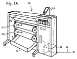
図1Aは、大判インクジェットプリンタを用いて印刷が得られる印刷装置を含む画像形成装置36を示す。大判画像形成装置36は、印刷アセンブリ、例えば図1Bに示すインクジェット印刷アセンブリが配置される筐体26を含む。画像形成装置36は、記録媒体28、30を格納する格納手段と、印刷後に記録媒体28、30を回収する排紙ステーションと、記録液20の貯蔵手段とを含む。図1Aでは、排紙ステーションは排紙トレイ32として具現化されている。任意で、排紙ステーションは、印刷後に記録媒体28、30を処理するための処理手段、例えば折機又はパンチャーを含んでいてもよい。大判画像形成装置36は、プリントジョブを受信するための手段と、任意でプリントジョブを操作するための手段をさらに含む。これらの手段は、ユーザーインターフェースユニット24及び/又は制御ユニット34、例えばコンピュータを含み得る。
FIG. 1A shows an
ロール28、30によって供給される記録媒体、例えば紙に画像が印刷される。ロール28はロール支持部R1で支持されているのに対して、ロール30はロール支持部R2で支持されている。あるいは、記録媒体のロール28、30に替えて、記録媒体のカットシートを用いてもよい。ロール28、30から切り落とされた印刷後の記録媒体のシートは排紙トレイ32に溜まる。
An image is printed on a recording medium supplied by the
印刷アセンブリで用いる各記録液は4つの容器20に貯蔵される。容器20は、プリントヘッドに記録液を供給するためにプリントヘッドとそれぞれ流体接続されるように構成されている。
Each recording liquid used in the printing assembly is stored in four
ローカルユーザーインターフェースユニット24はプリントエンジンと統合され、表示ユニット及び制御パネルを含み得る。あるいは、制御パネルは、例えばタッチスクリーン制御パネルの形で表示ユニットと統合されていてもよい。ローカルユーザーインターフェース24は、印刷装置36内に設置された制御ユニット34に接続されている。例えばコンピュータである制御ユニット34は、例えば印刷工程を制御するためにプリントエンジンにコマンドを出すように適合されたプロセッサを含む。画像形成装置36は任意でネットワークNに接続されていてもよい。ネットワークNへの接続をケーブル22の形で概略的に示しているが、該接続は無線によるものであってもよい。画像形成装置36は、ネットワークを介して印刷ジョブを受信し得る。また、USBポートを介してプリンタに印刷ジョブが送信されるように、プリンタのコントローラは任意でUSBポートを備えていてもよい。
The local user interface unit 24 is integrated with the print engine and may include a display unit and a control panel. Alternatively, the control panel may be integrated with the display unit, for example in the form of a touch screen control panel. The local user interface 24 is connected to a
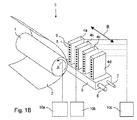
図1Bはインクジェット印刷アセンブリ3を示す。インクジェット印刷アセンブリ3は、記録媒体2を支持するための支持手段を含む。図1Bでは、支持手段としてプラテン1を示しているが、支持手段は代替的に平面であってもよい。図1Bに図示するプラテン1は、矢印Aで示すように、その軸を中心に回転可能な回転ドラムである。支持手段は、支持手段に対して記録媒体を固定位置で保持するための吸引孔を任意で備えていてもよい。インクジェット印刷アセンブリ3は、走査印刷キャリッジ5に搭載されたプリントヘッド4a〜4dを含む。走査印刷キャリッジ5は、好適な誘導手段6、7によって誘導されて、主走査方向Bに往復移動する。プリントヘッド4a〜4dのそれぞれはオリフィス面9を含み、オリフィス面9は少なくとも1つのオリフィス8を備えている。プリントヘッド4a〜4dは、記録媒体2に対して記録液の液滴を噴出するように構成されている。プラテン1、キャリッジ5及びプリントヘッド4a〜4dは、それぞれ好適な制御手段10a、10b及び10cによって制御される。
FIG. 1B shows an inkjet printing assembly 3. The ink jet printing assembly 3 includes support means for supporting the
記録媒体2はウェブ又はシート状の媒体であってもよく、例えば、紙、段ボール、ラベルシート(label stock)、コート紙、プラスチック又は織物で構成され得る。あるいは、記録媒体2は、エンドレス又は非エンドレスの中間部材であってもよい。循環的に動かされ得るエンドレス部材の例としては、ベルト又はドラムが挙げられる。記録媒体2は、流体の記録液を備える4つのプリントヘッド4a〜4dに沿って、プラテン1により副走査方向Aに動かされる。
The
走査印刷キャリッジ5は4つのプリントヘッド4a〜4dを運び、記録媒体2を主走査方向Bで走査できるように、プラテン1に対して平行な主走査方向Bに往復移動され得る。本発明を説明するために4つのプリントヘッド4a〜4dのみを図示している。実際には、任意数のプリントヘッドを用いてもよい。いずれの場合でも、記録液1色につき少なくとも1つのプリントヘッド4a〜4dが走査印刷キャリッジ5に配置される。例えば、白黒プリンタの場合では、一般に黒色の記録液を含む少なくとも1つのプリントヘッド4a〜4dが存在する。あるいは、白黒プリンタは、黒色の記録媒体2に適用される白色の記録液を含んでもよい。複数の色を含むフルカラープリンタの場合では、各色(通例、黒、シアン、マゼンタ及び黄色)につき少なくとも1つのプリントヘッド4a〜4dが存在する。フルカラープリンタでは、黒色の記録液は他の色の記録液に比べて頻繁に使用されることが多い。そのため、黒色の記録液を含むプリントヘッド4a〜4dを、他の色の記録液を含むプリントヘッド4a〜4dよりも多く走査印刷キャリッジ5に設けてもよい。あるいは、黒色の記録液を含むプリントヘッド4a〜4dは、他の色の記録液を含むプリントヘッド4a〜4dよりも大きくてもよい。
The scanning print carriage 5 carries the four
キャリッジ5は誘導手段6、7によって誘導される。これらの誘導手段6、7は、図1Bに示すように棒であり得る。これらの棒は、好適な駆動手段(図示せず)によって駆動され得る。あるいは、キャリッジ5は、他の誘導手段、例えばキャリッジ5を移動させることが可能なアームによって誘導されてもよい。他の代替案としては、記録媒体2を主走査方向Bに動かすことが挙げられる。
The carriage 5 is guided by guiding
各プリントヘッド4a〜4dは、少なくとも1つのオリフィス8を有するオリフィス面9を含む。少なくとも1つのオリフィス8は、プリントヘッド4a〜4d内に設けられた、流体の記録液を含む圧力室と流体連通されている。オリフィス面9には、複数のオリフィス8が副走査方向Aに対して平行に一直線に並んでいる。図1Bでは、プリントヘッド4a〜4dにつき8つのオリフィス8を図示しているが、実際の実施形態では、プリントヘッド4a〜4につき数百のオリフィス8が設けられ、任意でそれらが複数の列に並び得ることが分かる。図1Bに図示するように、プリントヘッド4a〜4dのそれぞれは、プリントヘッド4a〜4dのそれぞれに対応するオリフィス8が主走査方向Bにおいて一列に並んで配置されるように、互いに平行に配置されている。これは、最大で4つのオリフィス8(それぞれが別々のプリントヘッド4a〜4dの一部を成している)を選択的に作動させることで、主走査方向Bに線状に並んだ画像ドットが形成され得ることを意味する。この、プリントヘッド4a〜4dを平行に配列し、それに対応してオリフィス8を一列に並べる構成は、生産性の向上及び/又は印刷品質の改善にとって有利である。あるいは、プリントヘッド4a〜4dのそれぞれのオリフィス8が、一列ではなくジグザグ状(staggered configuration)に配置されるように、複数のプリントヘッド4a〜4dを印刷キャリッジ上に隣接配置してもよい。例えば、これは、印刷解像度を高めるか又は有効印刷領域を拡大するために行われ得る(主走査方向に一回走査することで対処され得る)。オリフィス8から記録液の液滴を噴出することによって画像ドットが形成される。
Each
記録液を噴出する際、記録液の一部がこぼれてプリントヘッド4a〜4dのオリフィス面9に残留することがある。オリフィス面9上に存在するインクは、液滴の噴出及びこれらの液滴を記録媒体2に配置する上で悪影響を及ぼすことがある。従って、過剰なインクをオリフィス面9から取り除くことが有利であり得る。過剰なインクは、例えばワイパーで拭き取ること及び/又は例えばコーティングによってもたらされる表面の好適な抗濡れ性により取り除かれ得る。
When the recording liquid is ejected, a part of the recording liquid may spill and remain on the
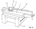
図1Cは、平らなプラテン1を有する平台印刷装置14を示す。平らなプラテン1はその上に置かれた記録媒体を支持する。平らなプラテン1は、当該技術分野で公知なように、負圧(under pressure)を生成してプラテン1の上で記録媒体を保持するための真空ポンプに作動的に連結された吸引孔を備え得る。ガントリ16は、キャリッジ5を主走査方向Bに誘導するための誘導手段を提供する。ガントリ16は副走査方向Aに移動可能である。よって、キャリッジ5は主走査方向B及び副走査方向Aの双方に移動できるため、平らなプラテン1上の任意の位置を印刷することができる。以下で説明するように、プラテン1及びガントリ16(キャリッジ5及びその上に配置された任意のプリントヘッドを含む)は支持構造体12上で支持されている。
FIG. 1C shows a
複数のインクジェットプリントヘッド(図示せず)がキャリッジ5上に配置されており、プラテン1の上に配置された媒体に記録液の液滴を提供するように構成されている。通常、キャリッジ5は、液滴のパスを提供するためにガントリ16に沿って主走査方向Bに移動する。その後、ガントリ16が副走査方向Aに所定の距離移動し、その後、キャリッジ5の次のストロークがガントリ16に沿って行われる。前記所定の距離は、当該技術分野で公知なように、高密度の液滴を提供するマルチパス印刷が可能となるようにパスの幅以下であり得る。
A plurality of ink jet print heads (not shown) are disposed on the carriage 5 and configured to provide recording liquid droplets to a medium disposed on the
インクジェット印刷アセンブリ3及び/又は平台印刷装置14は、硬化性の記録液、例えば紫外線の照射により硬化し得るUV硬化性の記録液を使用し得る。当該技術分野では既知なように、記録液は室温で吐出されるか又は高温に加熱され得る。具体的には、UV硬化性のインク組成物は、約40℃〜約80℃の範囲の温度で吐出され得ることが知られている。しかしながら、記録液の特性及び/又は記録媒体の特性に応じて任意の他の好適な温度を用いてもよい。
The inkjet printing assembly 3 and / or the
そのような硬化性の記録液を利用する場合、キャリッジ5は、記録液を記録媒体上に適用した後に記録液を硬化するための硬化手段も備え得る。例えば、記録液が紫外線により硬化可能な場合、キャリッジ5は、好適なUVランプ等のUV輻射源を備え得る。具体的には、係る輻射線は、プリントヘッドの下流側で走査方向に配置され得る。印刷アセンブリ3及び/又は印刷装置14が2方向で印刷を行う場合は、双方の方向で硬化できるようにプリントヘッドの両側に輻射源が配置され得る。
When such a curable recording liquid is used, the carriage 5 may also include a curing unit for curing the recording liquid after the recording liquid is applied onto the recording medium. For example, when the recording liquid can be cured by ultraviolet rays , the carriage 5 may include a UV radiation source such as a suitable UV lamp. Specifically, such radiation can be arranged in the scanning direction downstream of the print head. If the printing assembly 3 and / or the
図2Aは、記録媒体2に適用された第1の液滴40及び第2の液滴42を示す。第1の液滴40及び第2の液滴42はインクジェットプリントヘッドによって適用されており、硬化性の液体で構成されている。記録媒体2に衝突する際に、また液体の特性及び記録媒体2に特性によって、第1の液滴40及び第2の液滴42は、関連する物理的な力の全ての平衡状態が得られるまで記録媒体2の上で広がる。そのような物理的な力としては表面張力、粘度、濡れ性等が挙げられる。そのため、結果として生じる液滴のサイズ及び形状はこれらの物理的力によって決定される。図2Aでは、第1の液滴40の幅は40−Wであり高さは40−Hである。また、印刷解像度や液滴の配置によっては、第1の液滴40及び第2の液滴42は、図2に示すように記録媒体2の上で別々のドットの状態のままであり得る。第1の液滴40及び第2の液滴42が図示の状態で硬化された場合は、上面の形状によりマット仕上げが得られることになる。
FIG. 2A shows the
高光沢仕上げを所望する場合、平らで滑らかな上面が必要となる。そのため、隣接する液滴が一層広がって合体することが好ましいと考えられる。図2Bでは、2つの液滴から、例えば第1の液滴40及び第2の液滴42から大きな液滴44が形成されている。第1の液滴40及び第2の液滴42が一層広がることによって幅40−Wが増加して、液滴40、42が接触、合体し1つの液滴44を形成している。液滴が合体すること及び広がることによって上面が一層平坦且つ滑らかになり、それに対応してより高い光沢仕上げが得られる。
If a high gloss finish is desired, a flat and smooth top surface is required. For this reason, it is considered preferable that adjacent droplets further spread and coalesce. In FIG. 2B, a
光沢仕上げを得るためには、液滴が広がること及び合体すること(spreading and coalescing)が重要である。しかしながら、記録媒体2の特性及び液体と記録媒体との相互作用によって適用後の実際の広がりが決定される。従って、従来技術では、使用する記録媒体2から独立して結果として生じる光沢レベルを制御するのが困難であった。
In order to obtain a glossy finish, it is important that the droplets spread and coalescing. However, the actual spread after application is determined by the characteristics of the
本発明によれば、図3A及び図3Bに示すように、先ず液体の第1の層を適用し、記録媒体を覆う係る層をその光沢のレベルに関係なく硬化することにより、記録媒体の種類の影響を無関係にし得る。そのため、硬化した第1の層46が記録媒体2上に提供される。そして、図3Aを参照して、第1の液滴40及び第2の液滴42を適用することにより第2の層が提供され得る。この状態では、幅40−W及び高さ40−Hは、第1の液滴40及び第2の液滴42の液体の特性並びに硬化した第1の層46の特性(先に提供されているために事前に分かっている)によって決定される。そのため、印刷工程並びに液滴が広がること及び合体することが、所望の上面形状が得られるように制御選択され得る。そのため、必要に応じて、図3Aに示すようにマット仕上げが得られるか又は図3Bに示すように高光沢仕上げが得られ得る。図3Bでは、第1の液滴40及び第2の液滴42は、実質的に平らで滑らかな上面44−Sが得られるように合体し、大きく広がっている。
According to the present invention, as shown in FIGS. 3A and 3B, the first layer of liquid is first applied, and the layer covering the recording medium is cured regardless of its gloss level, so that the type of recording medium Can be irrelevant. Therefore, the cured
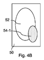
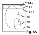
一実施形態では、前記液体は、ワニス等の透明又は少なくとも半透明な液体である。ワニスの使用により、画像に対して選択的に光沢を加えることができる。図4Aに示すように、記録媒体50には、第1の画像部分52及び第2の画像部分54で構成される画像が設けられている。係る画像は同じ印刷装置により提供されていてもよいし、別の印刷装置を用いて提供されていてもよい。また、UV硬化性インク等の同様のインクによって形成されていてもよいし、水性インク等の任意の他の好適なインクにより形成されていてもよい。ここでは、第2の画像部分54に光沢を加えることを意図するものとする。
In one embodiment, the liquid is a transparent or at least translucent liquid such as varnish. By using the varnish, it is possible to selectively add gloss to the image. As shown in FIG. 4A, the
本発明によれば、第2の画像部分54に光沢を提供するために、図4Bに示すようにワニスの第1の層が第2の画像部分54に適用される。例えば、図1Cに図示のような、キャリッジ上に配置された複数のプリントヘッドと該プリントヘッドの下流側に配置された硬化手段とを有する走査印刷装置を使用して、ワニスの小さな液滴が適用され、可能な限り早く硬化される。そのため、第2の画像部分54の上のみに比較的薄い硬化した第1の層54−1が提供される。
In accordance with the present invention, a first layer of varnish is applied to the
比較的薄い硬化した第1の層54−1を提供した後、比較的薄い硬化した第1の層54−1の上にワニスの第2の層が適用される。第2の層は、より多くの液体を含むより大きい液滴を適用することにより提供される。係るより大きい液滴はより多くの液体を含んでいるため、広がり及び合体が一層大きい。適用した液滴の広がり及び合体が十分になり所望のレベルになるまで硬化は行われない。その後、第2の層も硬化されて、図4Cに示す比較的厚い硬化した第2の層54−2が提供される。そのため、第2の画像部分54の所望の光沢レベルが得られる。
After providing the relatively thin cured first layer 54-1, a second layer of varnish is applied over the relatively thin cured first layer 54-1. The second layer is provided by applying larger droplets that contain more liquid. Such larger droplets contain more liquid and therefore are more spread and coalesced. Curing does not take place until the applied droplets are sufficiently spread and coalesced to the desired level. Thereafter, the second layer is also cured to provide a relatively thick cured second layer 54-2 shown in FIG. 4C. Therefore, a desired gloss level of the
図5A〜図5Eは本発明の一実施形態を示す。係る実施形態では、液体、例えばワニスのパスを互いに隣接して適用して1つの層が形成される。この実施形態では、パスが別々に適用されていることに起因して、アーチファクトなしで滑らかな光沢が得られるものとする。図5A〜図5Dは、記録媒体50の大きな部分に亘ってワニスが適用されている状態を示しているが、図5Eに記載の方法は、図4A〜図4Cに示す方法を行うのにも利用され得る。いずれにせよ、図5A〜図5Eに関連する説明では、硬化したワニスの第1の層が予め適用されているものとする。図5A〜図5E及び説明は、本発明に従って第2の層を適用する方法を説明する。しかしながら、必要に応じて、第1の層も当然同様な形で適用され得る。
5A-5E illustrate one embodiment of the present invention. In such embodiments, a liquid, for example, a varnish of a path adjacent to applying one another one layer is formed. In this embodiment, it is assumed that smooth gloss can be obtained without artifacts due to the fact that the passes are applied separately. 5A to 5D show a state in which the varnish is applied over a large portion of the
図5Aは、第1の画像部分52及び第2の画像部分54を含む画像(図4A参照)が設けられた記録媒体50を示す。また、ワニスの第1のパス61を示す。第1のパスは、第1の方法ステップS1及び第2の方法ステップS2に従い(図5E)、インクジェットプリントヘッドによって一回のストロークで走査方向に適用されているが、第1のパスは、高解像度を提供するために記録媒体50の同じ領域の上で複数のストロークにより(当該技術分野ではマルチパス印刷法として知られている)及び/又はより大きい高さのストロークを提供するために隣り合って位置する複数のストロークにより形成され得る。
FIG. 5A shows a
第1のパス61は先端61−L及び後端61−Tを有する。先端61−L及び後端61−Tは、第1のパス61が延びる方向に延びている。
The
図5Bに示すように、また第2の方法ステップS2に従って、第1のパス61は第1の下位パス61−1及び第2の下位パス61−2に実質的に分かれる。第1の下位パス61−1は先端61−Lを含み、第2の下位パス61−2は後端61−Tを含む。
As shown in FIG. 5B, and in accordance with the second method step S2, the
第1のパス61を構成する液滴が十分に広がって合体している場合、即ち所望の程度まで広がって合体している場合及び/又は所定の期間の後に、少なくともワニスの非粘着面を提供するために、第3の方法ステップS3(図5E)として第1の下位パス61−1を前硬化させる。そのような非粘着面は、例えば表面へのゴミや埃の粒子の付着を防止する。しかしながら、ワニスの層は、第1の下位パス61−1が比較的柔軟な状態で留まり、好ましくない張力が係る層内で防止されるように完全には硬化されていない。第2の下位パス61−2は硬化されていないため、第2のパス62で適用されるワニスと合体及び混ざるようにすることができる。
Providing at least a non-adhesive surface of the varnish when the droplets constituting the
第4の方法ステップS4では、第2のパスが必要な場合に、係る第2のパス(n=2)の印刷を準備することによって方法が継続し、該方法は第5の方法ステップS5に進む。第5の方法ステップS5は、図5Cに示すように実質的に第3の下位パス62−3及び第4の下位パス62−4を含む第2のパス62を印刷することを含む。第2のパス62を適用した後、第2の下位パス61−2及び第3の下位パス62−3を前硬化させるが(図5E:第6の方法ステップS6)、第4の下位パス62−4に隣接して別のパスが適用され得るため第4の下位パス62−4は硬化させない。
In a fourth method step S4, if a second pass is required, the method continues by preparing for printing of the second pass (n = 2), and the method proceeds to the fifth method step S5. move on. Fifth method step S5 comprises printing the
そして、さらなるパスが必要な場合に、係るさらなるパスの印刷を準備することによって方法が継続し(図5E:第7の方法ステップS7:n=n+1)、第8の方法ステップS8では、次のパスが最後のパスかどうかが確認される(n=N?)。次のパスが最後のパスではない場合(第8のステップS8:n=N?:No)、次のパスが最後のパスになるまで第5、第6、第7及び第8の方法ステップが繰り返される。 Then, if further passes are required, the method continues by preparing for printing of such further passes (FIG. 5E: seventh method step S7: n = n + 1). In the eighth method step S8, It is checked whether the path is the last path (n = N?). If the next path is not the last path (eighth step S8: n = N ?: No), the fifth, sixth, seventh and eighth method steps are performed until the next path becomes the last path. Repeated.
図5A〜図5Dの例ではN=8である。そのため、7つのパス61〜67が適用されるまで第5、第6、第7及び第8の方法ステップが繰り返される。これらの7つのパスは14の下位パス61−1〜67−14を含み、本方法が第8のパス68の適用に進む前に14の下位パスのうち13の下位パス61−1〜67−13が前硬化される。 In the example of FIGS. 5A to 5D, N = 8. Therefore, the fifth, sixth, seventh and eighth method steps are repeated until seven passes 61-67 are applied. These seven paths include 14 sub- paths 61-1 to 67-14, and 13 sub- paths 61-1 to 67- out of 14 sub- paths before the method proceeds to application of the eighth path 68. 13 is precured.
次のパスが最後のパスである場合(第8のステップS8:n=N?:YES)、本方法は第9の方法ステップS9に進む。第9の方法ステップS9では第8のパス68が適用される。次の第10の方法ステップS10では、隣接するさらなるパスがもう適用されないため、第14の下位パス67−14及び第15の下位パス68−15が前硬化されるだけでなく、最後である第16の下位パス68−16も前硬化される。 If the next pass is the last pass (eighth step S8: n = N ?: YES), the method proceeds to the ninth method step S9. In a ninth method step S9, an eighth pass 68 is applied. In the next tenth method step S10, the 14th lower pass 67-14 and the 15th lower pass 68-15 are not only precured but also the last one since no further adjacent passes are applied anymore. The 16 lower passes 68-16 are also precured.
第10の方法ステップS10の後、ワニスの層が記録媒体50の上に提供される。係るワニスの層は前硬化されているためまだ比較的柔軟な状態であり、上記の適用及び硬化方法により滑らかな面を提供する。係るワニスの層はパスベースで適用されているため、バンディングが全く見られない。そして、第11の方法ステップS11では、ワニスの層全体が、例えば該層の各位置に所定量の硬化輻射線を提供することにより所望の程度に硬化される。硬化の後、印刷ジョブが完了する(第12の方法ステップS12として示す)。
After the tenth method step S10, a layer of varnish is provided on the
当然ながら、図5A〜図5Eに図示する実施形態は、結果に大きな影響を与えることなく適合され得る。例えば、パスが少なくとも2つの下位パスに実質的に分かれると説明したが、本方法は、先ず2つのパスを適用し、そして第1のパスを硬化し、次に第3のパスを適用し、そして第2のパスを硬化する、といったように行うこともできる。また、他の実施形態及び改作も考えられ、それらは当業者の範囲内にあり、印刷ジョブ、任意の印刷要件及び/又は他の特徴及び特性に応じて好適に選択される。 Of course, the embodiments illustrated in FIGS. 5A-5E can be adapted without significantly affecting the results. For example, although the path has been described as divided substantially into at least two sub-paths, the method is first applied to two paths, and curing the first pass, to apply the next third pass, Then, the second pass can be cured. Other embodiments and adaptations are also contemplated and are within the scope of those skilled in the art and are suitably selected depending on the print job, any printing requirements, and / or other features and characteristics.
本発明の詳細な実施形態を本明細書で開示してきたが、開示した実施形態は、様々な形で実施可能な本発明の例示に過ぎないことが分かる。従って、本明細書で開示した具体的な構造及び機能についての詳細を限定的に解釈するのではなく、請求項の根拠として及び事実上適切な全ての詳細構造で本発明を様々な形で用いるのを当業者に教示するための例示的根拠として解釈すべきである。特に、別々の従属項で提示及び記載の特徴は組み合わせで適用され得る。そのような請求項の任意の有利な組み合わせがここに開示される。 Although detailed embodiments of the present invention have been disclosed herein, it is understood that the disclosed embodiments are merely illustrative of the invention that can be implemented in various forms. Accordingly, it is not intended that the details of the specific structures and functions disclosed herein be limited, but instead be used in various forms as the basis for claims and in virtually any detail that is appropriate. Should be construed as an exemplary basis for teaching those skilled in the art. In particular, features presented and described in separate dependent claims may be applied in combination. Any advantageous combinations of such claims are disclosed herein.
また、本明細書で使用の用語及び表現は限定を意図したものではなく、むしろ本発明の理解可能な説明を提供するために用いたものである。本明細書で使用の「a」又は「an」は1つ以上と定義される。本明細書で使用の複数という用語は2つ以上と定義される。本明細書で使用の他のという用語は、少なくとも第2以上と定義される。本明細書で使用の含有する及び/又は有するという用語は、含む(即ち、オープンランゲージ)を意味すると定義される。本明細書で使用の連結されたという用語は、必ずしも直接的ではないが接続されていることと定義される。
本発明を説明してきたが、本発明は多くの方法で変更され得ることが明らかである。そのような変更は本発明の精神及び範囲からの逸脱と見做すべきではなく、そのような変更の全ては、当業者には明らかなように下記の請求項の範囲に含まれる。
Also, the terms and expressions used herein are not intended to be limiting, but rather are used to provide an understandable description of the invention. As used herein, “a” or “an” is defined as one or more. As used herein, the term plural is defined as two or more. The term other as used herein is defined as at least a second or more. As used herein, the terms containing and / or having are defined to mean including (ie, open language). The term linked as used herein is defined as being connected, though not necessarily directly.
Having described the invention, it should be apparent that the invention can be modified in many ways. Such modifications are not to be regarded as a departure from the spirit and scope of the invention, and all such modifications are within the scope of the following claims, as will be apparent to those skilled in the art.
Claims (10)
a)前記記録液の液滴の第1の層が前記記録媒体の一部を覆うように、該第1の層を前記記録媒体上に適用するステップと、
b)前記記録液が前記記録媒体上で広がって前記記録液の第1の層を形成するのに必要な時間に応じて第1の期間を選択するステップと、
c)前記第1の層の液滴を、適用後に前記第1の期間内で硬化させるステップと、
d)硬化した前記第1の層の上に前記記録液の液滴の第2の層を適用するステップと、
e)前記第2の層が平滑な光沢面を有するように前記記録液の液滴が広がって合体するのに必要な時間に応じて第2の期間を選択するステップと、
f)前記第2の層を、適用後に前記第2の期間硬化させないステップと、
g)前記第2の期間の後に前記第2の層を完全に硬化させるステップと、
を含み、
当該方法は、前記ステップgの前に、h)前記第2の層を少なくとも部分的に前硬化して非粘着面を提供するステップをさらに含む、方法。 A method of applying a layer of a recording liquid on a recording medium by applying droplets of a curable recording liquid using an inkjet printing technique, the method comprising:
a) applying the first layer onto the recording medium such that the first layer of droplets of the recording liquid covers a portion of the recording medium;
b) selecting a first period according to a time required for the recording liquid to spread on the recording medium to form the first layer of the recording liquid;
c) curing the droplets of the first layer within the first period after application;
d) applying a second layer of the recording liquid droplets onto the cured first layer;
e) selecting the second period according to the time required for the recording liquid droplets to spread and coalesce so that the second layer has a smooth glossy surface;
f) not curing the second layer after application for the second period of time;
g) completely curing the second layer after the second period;
Including
The method further comprises, prior to step g, h) at least partially precuring the second layer to provide a non-stick surface.
i)キャリッジであって、該キャリッジと前記記録媒体とは互いに相対的に走査方向に移動可能である、キャリッジと、
ii)前記キャリッジ上に配置されたインクジェットプリントヘッドと、
iii)前記キャリッジ上に配置された前記輻射線を生成するための輻射源であって、該輻射源は、前記走査方向において前記インクジェットプリントヘッドに対して下流側に配置されている、輻射源と、
を含み、
前記方法の前記ステップa〜cは、
a1)前記キャリッジと前記記録媒体とを互いに相対的に前記走査方向に動かすステップと、
a2)前記ステップa1を行いながら前記記録液の液滴を適用するステップと、
a3)前記ステップa2で適用した液滴を硬化させるために、前記ステップa1を行いながら前記輻射線を生成するステップと、
を含む、請求項4に記載の方法。 The method is performed by an inkjet printing apparatus, the inkjet printing apparatus comprising:
i) a carriage, the carriage and the recording medium being movable relative to each other in the scanning direction;
ii) an inkjet printhead disposed on the carriage;
iii) a radiation source for generating the radiation disposed on the carriage, the radiation source being disposed downstream of the inkjet print head in the scanning direction; ,
Including
The steps a to c of the method include
a1) moving the carriage and the recording medium relative to each other in the scanning direction;
a2) applying the recording liquid droplets while performing step a1;
a3) generating the radiation while performing the step a1 in order to cure the droplets applied in the step a2.
The method of claim 4 comprising:
c1)前記記録液の第1のパスを適用するステップであって、該第1のパスは第1の下位パス及び第2の下位パスを含み、該第1の下位パスは前記第1のパスの先端を含み、該第2の下位パスは前記第1のパスの後端を含む、ステップと、
c2)前記第1の下位パスを前硬化し、前記第2の下位パスは硬化させないステップと、
c3)第2のパスを適用するステップであって、該第2のパスは第3の下位パス及び第4の下位パスを含み、該第3の下位パスは前記第2のパスの先端を含み、該第4の下位パスは前記第2のパスの後端を含み、前記第2のパスの先端は前記第1のパスの後端に隣接して配置される、ステップと、
c4)前記第2の下位パス及び前記第3の下位パスを前硬化するステップと、
c5)先行する前記ステップc1〜c4で適用及び前硬化した前記記録液を完全に硬化するステップと、
を含む、請求項1に記載の方法。 The recording liquid is applied in a plurality of passes, each of the passes extending in a first direction, having a front end and a rear end, the front end and the rear end extending in the first direction, and the steps d to h. Is
c1) applying the first pass of the recording liquid, wherein the first pass includes a first lower pass and a second lower pass, and the first lower pass is the first pass. The second sub-path includes the rear end of the first path; and
c2) pre-curing the first sub-pass and not curing the second sub-pass;
c3) applying the second path, wherein the second path includes a third lower path and a fourth lower path, and the third lower path includes a tip of the second path. The fourth sub-path includes a trailing edge of the second path, and a leading edge of the second path is disposed adjacent to a trailing edge of the first path;
c4) pre-curing the second lower pass and the third lower pass;
c5) completely curing the recording liquid applied and precured in the preceding steps c1 to c4;
The method of claim 1 comprising:
a)前記記録液の液滴の第1の層が前記記録媒体の一部を覆うように、該第1の層を前記記録媒体上に適用するステップと、
b)前記記録液が前記記録媒体上で広がって前記記録液の第1の層を形成するのに必要な時間に応じて第1の期間を選択するステップと、
c)前記第1の層の液滴を、適用後に前記第1の期間内で硬化させるステップと、
d)硬化した前記第1の層の上に前記記録液の液滴の第2の層を適用するステップと、
e)前記第2の層が平滑な光沢面を有するように前記記録液の液滴が広がって合体するのに必要な時間に応じて第2の期間を選択するステップと、
f)前記第2の層を、適用後に前記第2の期間硬化させないステップと、
g)前記第2の期間の後に前記第2の層を完全に硬化させるステップと、
を行うように構成され、
当該インクジェット印刷装置は、前記ステップgの前に、前記第2の層を前硬化して非粘着面を提供するステップを行うようさらに構成されている、インクジェット印刷装置。 An ink jet printing apparatus including an ink jet print head configured to apply a recording liquid on a recording medium, and including a curing unit for curing the recording liquid, the ink jet printing apparatus comprising:
a) applying the first layer onto the recording medium such that the first layer of droplets of the recording liquid covers a portion of the recording medium;
b) selecting a first period according to a time required for the recording liquid to spread on the recording medium to form the first layer of the recording liquid;
c) curing the droplets of the first layer within the first period after application;
d) applying a second layer of the recording liquid droplets onto the cured first layer;
e) selecting the second period according to the time required for the recording liquid droplets to spread and coalesce so that the second layer has a smooth glossy surface;
f) not curing the second layer after application for the second period of time;
g) completely curing the second layer after the second period;
Configured to do
The inkjet printing apparatus is further configured to perform a step of precuring the second layer to provide a non-adhesive surface before the step g.
前記インクジェット印刷装置はさらにキャリッジを含み、該キャリッジと前記記録媒体とは互いに相対的に走査方向に移動可能であり、前記インクジェットプリントヘッドは該キャリッジ上に配置されており、
前記硬化手段は、前記キャリッジ上に配置されるとともに前記好適な輻射線を生成するための輻射源を含み、該輻射源は、前記走査方向において前記インクジェットプリントヘッドに対して下流側に配置され、
前記インクジェット印刷装置は、
a1)前記キャリッジと前記記録媒体とを互いに相対的に前記走査方向に動かすステップと、
a2)前記ステップa1を行いながら前記記録液の液滴を適用するステップと、
a3)前記ステップa2で適用した液滴を硬化するために、前記ステップa1を行いながら前記輻射線を生成するステップと、
を行うように構成されている、請求項9に記載のインクジェット印刷装置。
The recording liquid can be cured by irradiation with suitable radiation including ultraviolet rays,
The inkjet printing apparatus further includes a carriage, the carriage and the recording medium are movable relative to each other in the scanning direction, and the inkjet print head is disposed on the carriage,
The curing means is disposed on the carriage and includes a radiation source for generating the suitable radiation, the radiation source being disposed downstream of the inkjet print head in the scanning direction;
The inkjet printing apparatus includes:
a1) moving the carriage and the recording medium relative to each other in the scanning direction;
a2) applying the recording liquid droplets while performing step a1;
a3) generating the radiation while performing the step a1 in order to cure the droplet applied in the step a2.
The ink jet printing apparatus according to claim 9, wherein the ink jet printing apparatus is configured to perform.
Applications Claiming Priority (5)
| Application Number | Priority Date | Filing Date | Title |
|---|---|---|---|
| US201261705953P | 2012-09-26 | 2012-09-26 | |
| US61/705,953 | 2012-09-26 | ||
| EP12198398.5 | 2012-12-20 | ||
| EP12198398 | 2012-12-20 | ||
| PCT/EP2013/068764 WO2014048734A1 (en) | 2012-09-26 | 2013-09-10 | Method of applying a curable liquid and apparatus for performing this method |
Publications (3)
| Publication Number | Publication Date |
|---|---|
| JP2015530294A JP2015530294A (en) | 2015-10-15 |
| JP2015530294A5 JP2015530294A5 (en) | 2016-09-15 |
| JP6293151B2 true JP6293151B2 (en) | 2018-03-14 |
Family
ID=47559169
Family Applications (1)
| Application Number | Title | Priority Date | Filing Date |
|---|---|---|---|
| JP2015532371A Active JP6293151B2 (en) | 2012-09-26 | 2013-09-10 | Method for applying curable liquid and apparatus for performing the method |
Country Status (4)
| Country | Link |
|---|---|
| US (1) | US9242481B2 (en) |
| EP (1) | EP2909039B1 (en) |
| JP (1) | JP6293151B2 (en) |
| WO (1) | WO2014048734A1 (en) |
Families Citing this family (4)
| Publication number | Priority date | Publication date | Assignee | Title |
|---|---|---|---|---|
| CN104029505A (en) * | 2014-05-29 | 2014-09-10 | 深圳大洋洲印务有限公司 | Method for printing local transfer plain hologram paper serving as cigarette packets |
| JP6443034B2 (en) * | 2014-12-24 | 2018-12-26 | セイコーエプソン株式会社 | Printing apparatus, printed matter and printed matter manufacturing method |
| EP3422258B1 (en) * | 2017-06-27 | 2021-08-11 | Canon Production Printing Holding B.V. | Roll-fed printing apparatus, software medium, and method for controlling a roll-fed printing apparatus |
| EP4286483A1 (en) | 2022-05-31 | 2023-12-06 | Agfa Nv | Inkjet printing methods |
Family Cites Families (24)
| Publication number | Priority date | Publication date | Assignee | Title |
|---|---|---|---|---|
| EP1029686B1 (en) | 1999-02-17 | 2004-09-29 | Hewlett-Packard Company, A Delaware Corporation | Printing apparatus and method |
| US6447112B1 (en) | 2000-05-01 | 2002-09-10 | 3M Innovative Properties Company | Radiation curing system and method for inkjet printers |
| JP3805266B2 (en) * | 2002-02-27 | 2006-08-02 | Uht株式会社 | Ceramic laminate manufacturing equipment |
| DE10327083A1 (en) * | 2003-02-11 | 2004-08-19 | Giesecke & Devrient Gmbh | Security paper, for the production of bank notes, passports and identity papers, comprises a flat substrate covered with a dirt-repellent protective layer comprising at least two lacquer layers |
| US7510277B2 (en) * | 2004-03-01 | 2009-03-31 | Fujifilm Corporation | Image forming apparatus and method |
| JP2006027194A (en) * | 2004-07-21 | 2006-02-02 | Konica Minolta Holdings Inc | Inkjet recording method and device |
| JP5350584B2 (en) * | 2005-10-27 | 2013-11-27 | オセ−テクノロジーズ・ベー・ヴエー | Inkjet printing method and printer |
| JP4715478B2 (en) * | 2005-12-02 | 2011-07-06 | コニカミノルタエムジー株式会社 | Image recording method, image recording apparatus, and image recording system |
| JP4907413B2 (en) | 2006-09-29 | 2012-03-28 | 富士フイルム株式会社 | Inkjet recording method and inkjet recording apparatus |
| EP1930169A1 (en) | 2006-12-08 | 2008-06-11 | Agfa Graphics N.V. | Curing method for inkjet printing apparatus |
| GB2448695B (en) | 2007-04-23 | 2012-07-11 | Inca Digital Printers Ltd | Large-scale inkjet printer |
| JP5040832B2 (en) | 2008-06-30 | 2012-10-03 | セイコーエプソン株式会社 | Fluid ejecting apparatus and image forming method |
| EP2340937B1 (en) * | 2008-08-21 | 2018-09-26 | Roland DG Corporation | Ink jet type recording device and computer program |
| JP5223658B2 (en) | 2008-12-24 | 2013-06-26 | 富士ゼロックス株式会社 | Recording device |
| JP5604790B2 (en) | 2009-02-04 | 2014-10-15 | セイコーエプソン株式会社 | Printing method and printing apparatus |
| JP5112360B2 (en) | 2009-02-27 | 2013-01-09 | 株式会社ミマキエンジニアリング | Inkjet printer and printing method |
| JP2011062905A (en) * | 2009-09-17 | 2011-03-31 | Dainippon Screen Mfg Co Ltd | Printing apparatus |
| JP5250854B2 (en) * | 2009-11-30 | 2013-07-31 | コニカミノルタ株式会社 | Inkjet image forming method and inkjet ink set |
| ES2387341T3 (en) | 2009-12-21 | 2012-09-20 | Agfa Graphics N.V. | Single pass inkjet printing method |
| JP5936809B2 (en) * | 2010-02-26 | 2016-06-22 | 日立マクセル株式会社 | Ink composition for forming clear layer, coating method thereof, and printed matter using the same |
| WO2011144596A1 (en) | 2010-05-18 | 2011-11-24 | Agfa Graphics Nv | Method of preparing a flexographic printing master |
| US8408689B2 (en) | 2010-09-14 | 2013-04-02 | Xerox Corporation | Methods of adjusting gloss of images on substrates using ink partial-curing and contact leveling and apparatuses useful in forming images on substrates |
| JP5724285B2 (en) | 2010-10-19 | 2015-05-27 | 東洋製罐株式会社 | Printing seamless can and manufacturing method thereof |
| EP2633998B1 (en) | 2012-03-02 | 2020-10-21 | Agfa Nv | Use of a single pass inkjet printing device |
-
2013
- 2013-09-10 WO PCT/EP2013/068764 patent/WO2014048734A1/en active Application Filing
- 2013-09-10 EP EP13760048.2A patent/EP2909039B1/en not_active Revoked
- 2013-09-10 JP JP2015532371A patent/JP6293151B2/en active Active
-
2015
- 2015-03-11 US US14/645,125 patent/US9242481B2/en active Active
Also Published As
| Publication number | Publication date |
|---|---|
| WO2014048734A1 (en) | 2014-04-03 |
| EP2909039A1 (en) | 2015-08-26 |
| US9242481B2 (en) | 2016-01-26 |
| EP2909039B1 (en) | 2017-12-20 |
| US20150183234A1 (en) | 2015-07-02 |
| JP2015530294A (en) | 2015-10-15 |
Similar Documents
| Publication | Publication Date | Title |
|---|---|---|
| JP4187857B2 (en) | Multi-color liquid ink printer and printing method | |
| JP4942075B2 (en) | Inkjet recording apparatus and inkjet recording method | |
| US20050212852A1 (en) | Image forming apparatus and method | |
| JP6293151B2 (en) | Method for applying curable liquid and apparatus for performing the method | |
| US20060214970A1 (en) | Image forming apparatus and method | |
| JP2017517408A (en) | Flatbed printer assembly | |
| KR100379148B1 (en) | Print image generation method and printing system | |
| US7216947B2 (en) | Image forming apparatus and droplet ejection control method | |
| JP6390234B2 (en) | Image forming apparatus, image forming system, and method for producing printed matter | |
| JP2016055627A (en) | Image forming apparatus, ejection inspection method of transparent droplet and ejection inspection program of transparent droplet | |
| JP2011093120A (en) | Inkjet recording method and inkjet recording apparatus | |
| JP6384170B2 (en) | Image forming apparatus, image forming system, and method for producing printed matter | |
| JP7068846B2 (en) | Inkjet printing equipment | |
| JP2013022826A (en) | Image recording device, image recording method, program and program recording medium | |
| KR20060020670A (en) | Ink-jet printing | |
| US6913353B2 (en) | Inkjet fixer fluid applicator | |
| US7370928B2 (en) | Droplet discharge control method and liquid discharge apparatus | |
| JP2006297651A (en) | Ink jet printer | |
| US9833996B2 (en) | Orifice surface, print head comprising an orifice surface and method for forming the orifice surface | |
| EP3470234B1 (en) | A method for preventing bleeding at the border of an image element | |
| JP2007038679A (en) | Ink-jet printing using low-coverage overprinting | |
| US11987060B2 (en) | Image forming apparatus and image forming method | |
| US20080150990A1 (en) | Ink jet printing apparatus and ink absorber recovery method | |
| US20240100821A1 (en) | Method for controlling a digital inkjet printer | |
| JP2012101367A (en) | Inkjet recording device |
Legal Events
| Date | Code | Title | Description |
|---|---|---|---|
| A521 | Request for written amendment filed |
Free format text: JAPANESE INTERMEDIATE CODE: A523 Effective date: 20160729 |
|
| A621 | Written request for application examination |
Free format text: JAPANESE INTERMEDIATE CODE: A621 Effective date: 20160729 |
|
| A977 | Report on retrieval |
Free format text: JAPANESE INTERMEDIATE CODE: A971007 Effective date: 20170417 |
|
| A131 | Notification of reasons for refusal |
Free format text: JAPANESE INTERMEDIATE CODE: A131 Effective date: 20170425 |
|
| A521 | Request for written amendment filed |
Free format text: JAPANESE INTERMEDIATE CODE: A523 Effective date: 20170712 |
|
| A02 | Decision of refusal |
Free format text: JAPANESE INTERMEDIATE CODE: A02 Effective date: 20170801 |
|
| A521 | Request for written amendment filed |
Free format text: JAPANESE INTERMEDIATE CODE: A523 Effective date: 20171130 |
|
| A911 | Transfer to examiner for re-examination before appeal (zenchi) |
Free format text: JAPANESE INTERMEDIATE CODE: A911 Effective date: 20171207 |
|
| TRDD | Decision of grant or rejection written | ||
| A01 | Written decision to grant a patent or to grant a registration (utility model) |
Free format text: JAPANESE INTERMEDIATE CODE: A01 Effective date: 20180116 |
|
| A61 | First payment of annual fees (during grant procedure) |
Free format text: JAPANESE INTERMEDIATE CODE: A61 Effective date: 20180213 |
|
| R150 | Certificate of patent or registration of utility model |
Ref document number: 6293151 Country of ref document: JP Free format text: JAPANESE INTERMEDIATE CODE: R150 |
|
| R250 | Receipt of annual fees |
Free format text: JAPANESE INTERMEDIATE CODE: R250 |
|
| R250 | Receipt of annual fees |
Free format text: JAPANESE INTERMEDIATE CODE: R250 |
|
| R250 | Receipt of annual fees |
Free format text: JAPANESE INTERMEDIATE CODE: R250 |
|
| R250 | Receipt of annual fees |
Free format text: JAPANESE INTERMEDIATE CODE: R250 |