JP6283670B2 - Stratification of patients with heart failure - Google Patents
Stratification of patients with heart failure Download PDFInfo
- Publication number
- JP6283670B2 JP6283670B2 JP2015524260A JP2015524260A JP6283670B2 JP 6283670 B2 JP6283670 B2 JP 6283670B2 JP 2015524260 A JP2015524260 A JP 2015524260A JP 2015524260 A JP2015524260 A JP 2015524260A JP 6283670 B2 JP6283670 B2 JP 6283670B2
- Authority
- JP
- Japan
- Prior art keywords
- risk
- heart sound
- signal
- heart
- time interval
- Prior art date
- Legal status (The legal status is an assumption and is not a legal conclusion. Google has not performed a legal analysis and makes no representation as to the accuracy of the status listed.)
- Active
Links
- 206010019280 Heart failures Diseases 0.000 title claims description 52
- 238000013517 stratification Methods 0.000 title description 3
- 238000005259 measurement Methods 0.000 claims description 198
- 206010007556 Cardiac failure acute Diseases 0.000 claims description 96
- 230000005236 sound signal Effects 0.000 claims description 53
- 230000029058 respiratory gaseous exchange Effects 0.000 claims description 50
- 230000000694 effects Effects 0.000 claims description 47
- 230000000747 cardiac effect Effects 0.000 claims description 44
- 239000000090 biomarker Substances 0.000 claims description 40
- 238000012545 processing Methods 0.000 claims description 38
- 230000036387 respiratory rate Effects 0.000 claims description 35
- 238000009531 respiratory rate measurement Methods 0.000 claims description 17
- 238000001514 detection method Methods 0.000 claims description 15
- 230000000241 respiratory effect Effects 0.000 claims description 13
- 101800000407 Brain natriuretic peptide 32 Proteins 0.000 claims description 8
- 210000001765 aortic valve Anatomy 0.000 claims description 7
- 230000009084 cardiovascular function Effects 0.000 claims description 6
- 230000008859 change Effects 0.000 claims description 4
- 108020001621 Natriuretic Peptide Proteins 0.000 claims 1
- 102000004571 Natriuretic peptide Human genes 0.000 claims 1
- 239000000692 natriuretic peptide Substances 0.000 claims 1
- 238000000034 method Methods 0.000 description 22
- 238000004891 communication Methods 0.000 description 8
- 230000006870 function Effects 0.000 description 8
- 238000010586 diagram Methods 0.000 description 7
- 238000012544 monitoring process Methods 0.000 description 7
- 238000011002 quantification Methods 0.000 description 6
- 230000008569 process Effects 0.000 description 5
- 238000009125 cardiac resynchronization therapy Methods 0.000 description 4
- 230000004044 response Effects 0.000 description 3
- 238000012502 risk assessment Methods 0.000 description 3
- 230000000638 stimulation Effects 0.000 description 3
- 238000011282 treatment Methods 0.000 description 3
- 230000002861 ventricular Effects 0.000 description 3
- 238000012935 Averaging Methods 0.000 description 2
- 206010007558 Cardiac failure chronic Diseases 0.000 description 2
- 101800001904 NT-proBNP Proteins 0.000 description 2
- 102400001263 NT-proBNP Human genes 0.000 description 2
- 230000009471 action Effects 0.000 description 2
- 238000007726 management method Methods 0.000 description 2
- 230000007383 nerve stimulation Effects 0.000 description 2
- 230000035945 sensitivity Effects 0.000 description 2
- 238000000926 separation method Methods 0.000 description 2
- 238000002560 therapeutic procedure Methods 0.000 description 2
- 206010056370 Congestive cardiomyopathy Diseases 0.000 description 1
- 201000010046 Dilated cardiomyopathy Diseases 0.000 description 1
- 125000001429 N-terminal alpha-amino-acid group Chemical group 0.000 description 1
- 206010030124 Oedema peripheral Diseases 0.000 description 1
- 206010037423 Pulmonary oedema Diseases 0.000 description 1
- 230000009286 beneficial effect Effects 0.000 description 1
- 230000017531 blood circulation Effects 0.000 description 1
- 210000005242 cardiac chamber Anatomy 0.000 description 1
- 238000013194 cardioversion Methods 0.000 description 1
- 210000001326 carotid sinus Anatomy 0.000 description 1
- 238000004590 computer program Methods 0.000 description 1
- 230000008602 contraction Effects 0.000 description 1
- 238000012377 drug delivery Methods 0.000 description 1
- 238000001827 electrotherapy Methods 0.000 description 1
- 230000000004 hemodynamic effect Effects 0.000 description 1
- 210000004115 mitral valve Anatomy 0.000 description 1
- 238000012806 monitoring device Methods 0.000 description 1
- 210000004165 myocardium Anatomy 0.000 description 1
- 210000005036 nerve Anatomy 0.000 description 1
- 230000001537 neural effect Effects 0.000 description 1
- 230000003287 optical effect Effects 0.000 description 1
- 210000000056 organ Anatomy 0.000 description 1
- CWEFIMQKSZFZNY-UHFFFAOYSA-N pentyl 2-[4-[[4-[4-[[4-[[4-(pentoxycarbonylamino)phenyl]methyl]phenyl]carbamoyloxy]butoxycarbonylamino]phenyl]methyl]phenyl]acetate Chemical compound C1=CC(CC(=O)OCCCCC)=CC=C1CC(C=C1)=CC=C1NC(=O)OCCCCOC(=O)NC(C=C1)=CC=C1CC1=CC=C(NC(=O)OCCCCC)C=C1 CWEFIMQKSZFZNY-UHFFFAOYSA-N 0.000 description 1
- 230000004962 physiological condition Effects 0.000 description 1
- 230000001766 physiological effect Effects 0.000 description 1
- 230000035790 physiological processes and functions Effects 0.000 description 1
- 208000005333 pulmonary edema Diseases 0.000 description 1
- 238000000718 qrs complex Methods 0.000 description 1
- 230000000306 recurrent effect Effects 0.000 description 1
- 238000013468 resource allocation Methods 0.000 description 1
- 238000012552 review Methods 0.000 description 1
- 238000002633 shock therapy Methods 0.000 description 1
- 239000000126 substance Substances 0.000 description 1
- 238000006467 substitution reaction Methods 0.000 description 1
- 239000013589 supplement Substances 0.000 description 1
- 208000024891 symptom Diseases 0.000 description 1
- 230000001225 therapeutic effect Effects 0.000 description 1
- 238000012384 transportation and delivery Methods 0.000 description 1
- 210000001186 vagus nerve Anatomy 0.000 description 1
- 230000003442 weekly effect Effects 0.000 description 1
Images


Classifications
-
- A—HUMAN NECESSITIES
- A61—MEDICAL OR VETERINARY SCIENCE; HYGIENE
- A61B—DIAGNOSIS; SURGERY; IDENTIFICATION
- A61B5/00—Measuring for diagnostic purposes; Identification of persons
- A61B5/72—Signal processing specially adapted for physiological signals or for diagnostic purposes
- A61B5/7271—Specific aspects of physiological measurement analysis
- A61B5/7275—Determining trends in physiological measurement data; Predicting development of a medical condition based on physiological measurements, e.g. determining a risk factor
-
- A—HUMAN NECESSITIES
- A61—MEDICAL OR VETERINARY SCIENCE; HYGIENE
- A61B—DIAGNOSIS; SURGERY; IDENTIFICATION
- A61B5/00—Measuring for diagnostic purposes; Identification of persons
- A61B5/02—Detecting, measuring or recording pulse, heart rate, blood pressure or blood flow; Combined pulse/heart-rate/blood pressure determination; Evaluating a cardiovascular condition not otherwise provided for, e.g. using combinations of techniques provided for in this group with electrocardiography or electroauscultation; Heart catheters for measuring blood pressure
- A61B5/0205—Simultaneously evaluating both cardiovascular conditions and different types of body conditions, e.g. heart and respiratory condition
-
- A—HUMAN NECESSITIES
- A61—MEDICAL OR VETERINARY SCIENCE; HYGIENE
- A61B—DIAGNOSIS; SURGERY; IDENTIFICATION
- A61B5/00—Measuring for diagnostic purposes; Identification of persons
- A61B5/08—Detecting, measuring or recording devices for evaluating the respiratory organs
-
- A—HUMAN NECESSITIES
- A61—MEDICAL OR VETERINARY SCIENCE; HYGIENE
- A61B—DIAGNOSIS; SURGERY; IDENTIFICATION
- A61B5/00—Measuring for diagnostic purposes; Identification of persons
- A61B5/145—Measuring characteristics of blood in vivo, e.g. gas concentration, pH value; Measuring characteristics of body fluids or tissues, e.g. interstitial fluid, cerebral tissue
- A61B5/14546—Measuring characteristics of blood in vivo, e.g. gas concentration, pH value; Measuring characteristics of body fluids or tissues, e.g. interstitial fluid, cerebral tissue for measuring analytes not otherwise provided for, e.g. ions, cytochromes
-
- A—HUMAN NECESSITIES
- A61—MEDICAL OR VETERINARY SCIENCE; HYGIENE
- A61B—DIAGNOSIS; SURGERY; IDENTIFICATION
- A61B5/00—Measuring for diagnostic purposes; Identification of persons
- A61B5/24—Detecting, measuring or recording bioelectric or biomagnetic signals of the body or parts thereof
- A61B5/316—Modalities, i.e. specific diagnostic methods
- A61B5/318—Heart-related electrical modalities, e.g. electrocardiography [ECG]
- A61B5/346—Analysis of electrocardiograms
- A61B5/349—Detecting specific parameters of the electrocardiograph cycle
-
- A—HUMAN NECESSITIES
- A61—MEDICAL OR VETERINARY SCIENCE; HYGIENE
- A61B—DIAGNOSIS; SURGERY; IDENTIFICATION
- A61B5/00—Measuring for diagnostic purposes; Identification of persons
- A61B5/68—Arrangements of detecting, measuring or recording means, e.g. sensors, in relation to patient
- A61B5/6801—Arrangements of detecting, measuring or recording means, e.g. sensors, in relation to patient specially adapted to be attached to or worn on the body surface
-
- A—HUMAN NECESSITIES
- A61—MEDICAL OR VETERINARY SCIENCE; HYGIENE
- A61B—DIAGNOSIS; SURGERY; IDENTIFICATION
- A61B5/00—Measuring for diagnostic purposes; Identification of persons
- A61B5/68—Arrangements of detecting, measuring or recording means, e.g. sensors, in relation to patient
- A61B5/6846—Arrangements of detecting, measuring or recording means, e.g. sensors, in relation to patient specially adapted to be brought in contact with an internal body part, i.e. invasive
- A61B5/6847—Arrangements of detecting, measuring or recording means, e.g. sensors, in relation to patient specially adapted to be brought in contact with an internal body part, i.e. invasive mounted on an invasive device
- A61B5/686—Permanently implanted devices, e.g. pacemakers, other stimulators, biochips
-
- A—HUMAN NECESSITIES
- A61—MEDICAL OR VETERINARY SCIENCE; HYGIENE
- A61B—DIAGNOSIS; SURGERY; IDENTIFICATION
- A61B5/00—Measuring for diagnostic purposes; Identification of persons
- A61B5/74—Details of notification to user or communication with user or patient ; user input means
- A61B5/746—Alarms related to a physiological condition, e.g. details of setting alarm thresholds or avoiding false alarms
-
- A—HUMAN NECESSITIES
- A61—MEDICAL OR VETERINARY SCIENCE; HYGIENE
- A61B—DIAGNOSIS; SURGERY; IDENTIFICATION
- A61B7/00—Instruments for auscultation
-
- A—HUMAN NECESSITIES
- A61—MEDICAL OR VETERINARY SCIENCE; HYGIENE
- A61B—DIAGNOSIS; SURGERY; IDENTIFICATION
- A61B7/00—Instruments for auscultation
- A61B7/003—Detecting lung or respiration noise
-
- A—HUMAN NECESSITIES
- A61—MEDICAL OR VETERINARY SCIENCE; HYGIENE
- A61B—DIAGNOSIS; SURGERY; IDENTIFICATION
- A61B7/00—Instruments for auscultation
- A61B7/02—Stethoscopes
- A61B7/04—Electric stethoscopes
-
- G—PHYSICS
- G16—INFORMATION AND COMMUNICATION TECHNOLOGY [ICT] SPECIALLY ADAPTED FOR SPECIFIC APPLICATION FIELDS
- G16H—HEALTHCARE INFORMATICS, i.e. INFORMATION AND COMMUNICATION TECHNOLOGY [ICT] SPECIALLY ADAPTED FOR THE HANDLING OR PROCESSING OF MEDICAL OR HEALTHCARE DATA
- G16H40/00—ICT specially adapted for the management or administration of healthcare resources or facilities; ICT specially adapted for the management or operation of medical equipment or devices
- G16H40/60—ICT specially adapted for the management or administration of healthcare resources or facilities; ICT specially adapted for the management or operation of medical equipment or devices for the operation of medical equipment or devices
- G16H40/63—ICT specially adapted for the management or administration of healthcare resources or facilities; ICT specially adapted for the management or operation of medical equipment or devices for the operation of medical equipment or devices for local operation
-
- G—PHYSICS
- G16—INFORMATION AND COMMUNICATION TECHNOLOGY [ICT] SPECIALLY ADAPTED FOR SPECIFIC APPLICATION FIELDS
- G16H—HEALTHCARE INFORMATICS, i.e. INFORMATION AND COMMUNICATION TECHNOLOGY [ICT] SPECIALLY ADAPTED FOR THE HANDLING OR PROCESSING OF MEDICAL OR HEALTHCARE DATA
- G16H50/00—ICT specially adapted for medical diagnosis, medical simulation or medical data mining; ICT specially adapted for detecting, monitoring or modelling epidemics or pandemics
- G16H50/30—ICT specially adapted for medical diagnosis, medical simulation or medical data mining; ICT specially adapted for detecting, monitoring or modelling epidemics or pandemics for calculating health indices; for individual health risk assessment
-
- G—PHYSICS
- G16—INFORMATION AND COMMUNICATION TECHNOLOGY [ICT] SPECIALLY ADAPTED FOR SPECIFIC APPLICATION FIELDS
- G16H—HEALTHCARE INFORMATICS, i.e. INFORMATION AND COMMUNICATION TECHNOLOGY [ICT] SPECIALLY ADAPTED FOR THE HANDLING OR PROCESSING OF MEDICAL OR HEALTHCARE DATA
- G16H50/00—ICT specially adapted for medical diagnosis, medical simulation or medical data mining; ICT specially adapted for detecting, monitoring or modelling epidemics or pandemics
- G16H50/70—ICT specially adapted for medical diagnosis, medical simulation or medical data mining; ICT specially adapted for detecting, monitoring or modelling epidemics or pandemics for mining of medical data, e.g. analysing previous cases of other patients
-
- A—HUMAN NECESSITIES
- A61—MEDICAL OR VETERINARY SCIENCE; HYGIENE
- A61B—DIAGNOSIS; SURGERY; IDENTIFICATION
- A61B5/00—Measuring for diagnostic purposes; Identification of persons
- A61B5/24—Detecting, measuring or recording bioelectric or biomagnetic signals of the body or parts thereof
- A61B5/316—Modalities, i.e. specific diagnostic methods
- A61B5/318—Heart-related electrical modalities, e.g. electrocardiography [ECG]
-
- A—HUMAN NECESSITIES
- A61—MEDICAL OR VETERINARY SCIENCE; HYGIENE
- A61B—DIAGNOSIS; SURGERY; IDENTIFICATION
- A61B5/00—Measuring for diagnostic purposes; Identification of persons
- A61B5/68—Arrangements of detecting, measuring or recording means, e.g. sensors, in relation to patient
- A61B5/6846—Arrangements of detecting, measuring or recording means, e.g. sensors, in relation to patient specially adapted to be brought in contact with an internal body part, i.e. invasive
- A61B5/6867—Arrangements of detecting, measuring or recording means, e.g. sensors, in relation to patient specially adapted to be brought in contact with an internal body part, i.e. invasive specially adapted to be attached or implanted in a specific body part
- A61B5/6869—Heart
Landscapes
- Health & Medical Sciences (AREA)
- Life Sciences & Earth Sciences (AREA)
- Engineering & Computer Science (AREA)
- Medical Informatics (AREA)
- Public Health (AREA)
- Biomedical Technology (AREA)
- General Health & Medical Sciences (AREA)
- Animal Behavior & Ethology (AREA)
- Surgery (AREA)
- Molecular Biology (AREA)
- Heart & Thoracic Surgery (AREA)
- Veterinary Medicine (AREA)
- Pathology (AREA)
- Physics & Mathematics (AREA)
- Biophysics (AREA)
- Physiology (AREA)
- Cardiology (AREA)
- Pulmonology (AREA)
- Primary Health Care (AREA)
- Data Mining & Analysis (AREA)
- Epidemiology (AREA)
- Databases & Information Systems (AREA)
- Psychiatry (AREA)
- Signal Processing (AREA)
- Artificial Intelligence (AREA)
- Computer Vision & Pattern Recognition (AREA)
- General Business, Economics & Management (AREA)
- Business, Economics & Management (AREA)
- Acoustics & Sound (AREA)
- Optics & Photonics (AREA)
- Measuring Pulse, Heart Rate, Blood Pressure Or Blood Flow (AREA)
- Measuring And Recording Apparatus For Diagnosis (AREA)
- Measurement Of The Respiration, Hearing Ability, Form, And Blood Characteristics Of Living Organisms (AREA)
Description
本発明は心不全患者の層別化に関する。 The present invention relates to stratification of heart failure patients.
携行型医療装置としては、植込み型医療装置(IMD)と着用型(ウエラブル)医療装置とが挙げられる。植込み型医療装置の一部の例としては、植込み型ペースメーカー、植込み型カルディオバータ除細動器(ICD)、心臓再同期療法装置(CRT)、及びそのような能力の組み合わせを備える装置などの心機能管理(CFM)装置が挙げられる。植込み型医療装置は、電気療法又は他の治療法を用いて患者もしくは対象者を治療するため、又は患者もしくは対象者の状態の内部監視によって患者の診断において医師又は介護者を支援するために用いられ得る。前記装置は、患者内における電気的な心臓活動を監視するために、1つ以上のセンス増幅器と連絡した1つ以上の電極を備え得る。また前記装置は、多くの場合において、1つ以上の他の内部患者パラメータを監視するために1つ以上のセンサーを備える。植込み型医療装置の他の例としては、植込み型診断装置、植込み型薬剤送達システム、又は神経刺激能を備えた植込み型装置が挙げられる。 Examples of the portable medical device include an implantable medical device (IMD) and a wearable medical device. Some examples of implantable medical devices include cardiac devices such as implantable pacemakers, implantable cardioverter defibrillators (ICDs), cardiac resynchronization therapy devices (CRTs), and devices with combinations of such capabilities. Examples include function management (CFM) devices. Implantable medical devices are used to treat a patient or subject using electrotherapy or other therapy, or to assist a physician or caregiver in diagnosing a patient by internal monitoring of the patient or subject's condition Can be. The device may include one or more electrodes in communication with one or more sense amplifiers to monitor electrical heart activity within the patient. The devices also often include one or more sensors to monitor one or more other internal patient parameters. Other examples of implantable medical devices include implantable diagnostic devices, implantable drug delivery systems, or implantable devices with neural stimulation capabilities.
着用型医療装置としては、着用型(ウエラブル)カルディオバータ除細動器(WCD)及び着用型診断装置(例えば携行型監視ベスト)が挙げられる。着用型カルディオバータ除細動器は表面電極を備えた監視装置であり得る。前記表面電極は、体表面心電図(ECG)を提供するための監視と、カルディオバータ及び除細動器ショック療法の送達とのうちの一方又は双方を提供するように配置される。携行型医療装置はまた、対象者の1つ以上の生理学的パラメータを監視するために1つ以上のセンサーを備え得る。 Wearable medical devices include wearable (wearable) cardioverter defibrillators (WCD) and wearable diagnostic devices (eg, portable monitoring vests). The wearable cardioverter defibrillator can be a monitoring device with a surface electrode. The surface electrode is arranged to provide one or both of monitoring to provide a body surface electrocardiogram (ECG) and delivery of cardioverter and defibrillator shock therapy. The portable medical device may also include one or more sensors to monitor one or more physiological parameters of the subject.
一部の携行型医療装置は、患者の異なる生理学的態様を監視するために1つ以上のセンサーを備える。この装置は、そのようなセンサーによって提供される電気信号から、室の充満及び収縮に関連する血行動態パラメータ又は他の生理学的パラメータの測定値を導出し得る。これらの装置を処方された患者は、繰り返す心不全(HF)代償不全、又は心不全の悪化(HF:WHF)に関連した他のイベントを経験していることもある。急性心不全に関連する症状としては、肺水腫及び/又は末梢性浮腫、拡張型心筋症又は心室拡張が挙げられ得る。慢性心不全を有する一部の患者は急性心不全イベントを経験することがある。装置に基づく監視は、急性心不全イベントを経験するリスク(危険性)を有するそれらの心不全患者を識別することができる。 Some portable medical devices include one or more sensors to monitor different physiological aspects of the patient. The device may derive measurements of hemodynamic or other physiological parameters related to chamber filling and contraction from electrical signals provided by such sensors. Patients who are prescribed these devices may also experience recurrent heart failure (HF) decompensation, or other events associated with worsening heart failure (HF: WHF). Symptoms associated with acute heart failure can include pulmonary edema and / or peripheral edema, dilated cardiomyopathy or ventricular dilatation. Some patients with chronic heart failure may experience an acute heart failure event. Device-based monitoring can identify those heart failure patients who are at risk of experiencing an acute heart failure event.
本発明は、心不全の検知のためのシステム、装置及び方法一般に関する。 The present invention relates generally to systems, devices and methods for the detection of heart failure.
装置の例は、少なくとも、対象者の心臓血管機能を表す第1の生理学的信号を生成するように構成された第1の生理学的センサー回路と、その第1の生理学的センサー回路に通信可能に接続された制御回路とを備える。前記制御回路は信号処理回路とリスク回路とを含み得る。前記信号処理回路は、第1の生理学的センサー信号を用いて第1の生理学的測定値を求め、第1所定期間にわたって生成される複数の第1の生理学的信号を用いて複数の第1の生理学的測定値を求めて、複数の生理学的測定値の中心傾向測定値を求めるように構成され得る。前記リスク回路は、例えば、求めた中心傾向測定値を急性心不全のリスクを示す1つ以上の基準と比較することを含むことにより、求めた中心傾向測定値を用いて、対象者に対する急性心不全のリスクを定量化するように構成され得る。前記制御回路
は、求めた中心傾向測定値と急性心不全のリスクを示す1つ以上の基準との比較に従って、急性心不全のリスクの表示を生成するように構成され得る。
An example apparatus is configured to communicate with at least a first physiological sensor circuit configured to generate at least a first physiological signal representative of a subject's cardiovascular function, and the first physiological sensor circuit. And a connected control circuit. The control circuit may include a signal processing circuit and a risk circuit. The signal processing circuit uses a first physiological sensor signal to determine a first physiological measurement and uses a plurality of first physiological signals generated over a first predetermined time period to generate a plurality of first physiological signals. A physiological measurement may be determined and configured to determine a central trend measurement of the plurality of physiological measurements. The risk circuit includes, for example, comparing the determined central tendency measurement with one or more criteria indicative of the risk of acute heart failure, thereby using the determined central tendency measurement to determine the acute heart failure for the subject. It can be configured to quantify the risk. The control circuit may be configured to generate an indication of the risk of acute heart failure according to a comparison of the determined central trend measurement with one or more criteria indicative of the risk of acute heart failure.
本節は、本特許出願の主題の概要を提供するものである。本概要は、本発明の排他的又は網羅的な説明を提供するものではない。本特許出願についてのさらに詳細な情報を提供するために、詳細な説明が含まれている。 This section provides an overview of the subject matter of this patent application. This summary is not intended to provide an exclusive or exhaustive description of the invention. A detailed description is included to provide more detailed information about the present patent application.
必ずしも一定の縮尺で描かれていない図面において、同一の数字は、異なる視野における類似した構成要素を説明し得る。異なる文字の接尾辞を有する同一の数字は、類似した構成要素の異なる例を表わし得る。図面は、概して、本文書で検討される様々な実施例を、例として示しているが、限定するためではない。 In the drawings, which are not necessarily drawn to scale, the same numerals may describe similar components in different fields of view. Identical numbers with different letter suffixes may represent different examples of similar components. The drawings generally illustrate, by way of example, and not limitation, the various embodiments discussed in this document.
携行型医療装置は、例えば日常生活動作中に長期にわたって、対象者とともに移動することができる。そのような装置は、本願に記載する特徴、構造、方法又はそれらの組み合わせのうちの1つ以上を包含し得る。例えば、心臓モニタ又は心臓刺激装置は下記に述べる有益な特徴及び/又はプロセスの1つ以上を包含するように実施され得る。そのようなモニタ、刺激装置、又は他の植込み型もしくは部分植込み型装置は、本願に記載する特徴のすべてを備える必要はないが、独特の構造又は機能性を提供する選択された特徴を備えるように実施され得ることが意図される。そのような装置は様々な治療又は診断機能を提供するように実施され得る。 The portable medical device can move with the subject over a long period of time, for example, during daily life operations. Such a device can include one or more of the features, structures, methods, or combinations thereof described herein. For example, a cardiac monitor or cardiac stimulator can be implemented to include one or more of the beneficial features and / or processes described below. Such a monitor, stimulator, or other implantable or partially implantable device need not have all of the features described herein, but with selected features that provide unique structure or functionality. It is intended that it can be implemented. Such devices can be implemented to provide various therapeutic or diagnostic functions.
本願では、患者の急性心不全の評価のためのシステム及び方法の改良について記載する。慢性心不全を有する患者は急性心不全イベント(例えば心不全代償不全イベント)を経験することがある。限られた保険医療資源のために、危険に瀕しているそれらの患者を識別し、それに従って医療資源を割り当てることが望ましいことがある。心不全に対する装置生成リスク指標は、比較的高い急性心不全のリスクを有するそれらの患者を識別するか、又は、これに代わって、比較的低い急性心不全のリスクを有する患者を識別し、すべての心不全患者に対して同様の保険医療の質を維持しながら、心不全を監視及び治療するための資源を割り当てることを支援し得る。 This application describes improvements to systems and methods for the assessment of acute heart failure in patients. Patients with chronic heart failure may experience acute heart failure events (eg, heart failure decompensation events). Because of limited insurance medical resources, it may be desirable to identify those patients at risk and allocate medical resources accordingly. The device-generated risk index for heart failure identifies those patients who have a relatively high risk of acute heart failure, or alternatively identifies patients who have a relatively low risk of acute heart failure, and all heart failure patients Can help allocate resources to monitor and treat heart failure while maintaining similar insurance quality.
医療用電子装置は患者の生理学的状態に関連する情報を得るために用いることができる
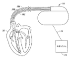
。図1は、植込み型医療装置110を含むシステム100の一部の図である。植込み型医療装置110の例としては、ペースメーカー、除細動器、心臓再同期療法(CRT)装置又はそのような装置の組み合わせが挙げられるが、これらに限定されるわけではない。植込み型医療装置110は、1つ以上のリード108A〜108Cによって心臓105に接続され得る。心臓リード108A〜108Cは、植込み型医療装置110に接続された基端部と、電気接点又は「電極」によって心臓105の1つ以上の部分に接続された先端部とを備える。前記電極は、カルディオバージョン、除細動、ペーシング、又は再同期療法、又はそれらの組み合わせを提供するために、心臓105に電気的刺激を送達するように構成され得る。前記電極は、電気的心臓信号を感知するために、センス増幅器に電気的に接続されていてもよい。
The medical electronic device can be used to obtain information related to the patient's physiological condition. FIG. 1 is a diagram of a portion of a
医療用電子装置はまた、他の生理学的パラメータを監視するために他の生理学的センサーを備えてもよい。例えば、着用型装置は、心電計(ECG)のような心臓信号を感知するために表面電極(例えば皮膚接触用電極)を備え得る。別の例において、生理学的センサーは、心音を感知する心音センサー回路を備え得る。心音は、対象者の心臓の活動及び心臓を通る血液の流れからの機械的振動に関連している。心音は各心周期で繰り返し、振動に関連する活動に従って分離され、分類され得る。第1心音(S1)は、僧帽弁の緊張中に心臓によって生成される震動音である。第2心音(S2)は、大動脈弁の閉鎖及び心拡張期の開始を示している。第3心音(S3)及び第4音(S4)は心拡張期中における左心室の充満圧に関連する。心音センサー回路は、患者の心臓の機械的活動を示す電気的な生理学的信号を生成することができる。心音センサー回路は、心臓内、心臓付近、植込み型医療装置内、患者の皮膚上の着用型パッチ内、又は心音の音響エネルギーが感知され得る別の場所に配置され得る。いくつかの例において、前記心音センサー回路は、図1の植込み型医療装置内に配置された加速度計を備える。別の例において、心音センサー回路は、心臓105の音響エネルギー又は振動を感知するためにマイクロホンを備える。
The medical electronic device may also include other physiological sensors to monitor other physiological parameters. For example, the wearable device may include a surface electrode (eg, a skin contact electrode) for sensing cardiac signals such as an electrocardiograph (ECG). In another example, the physiological sensor may comprise a heart sound sensor circuit that senses heart sounds. Heart sounds are related to the subject's heart activity and mechanical vibrations from blood flow through the heart. Heart sounds are repeated in each cardiac cycle and can be separated and classified according to activity associated with vibration. The first heart sound (S1) is a vibration sound generated by the heart during mitral valve tension. The second heart sound (S2) indicates the closure of the aortic valve and the beginning of the diastole. The third heart sound (S3) and the fourth sound (S4) are related to the left ventricular filling pressure during diastole. The heart sound sensor circuit can generate an electrical physiological signal indicative of the mechanical activity of the patient's heart. The heart sound sensor circuit may be placed in the heart, near the heart, in an implantable medical device, in a wearable patch on the patient's skin, or elsewhere where the acoustic energy of the heart sound can be sensed. In some examples, the heart sound sensor circuit comprises an accelerometer disposed within the implantable medical device of FIG. In another example, the heart sound sensor circuit includes a microphone to sense the acoustic energy or vibration of the
図1に示したように、前記システムは無線信号190によって植込み型医療装置110と通信する医療装置プログラマ又は他の外部システム170を備え得る。いくつかの例において、無線通信は高周波(RF)を用いることを含み得る。しかしながら、他の適当な遠隔測定信号(テレメトリー信号)を用いることができる。
As shown in FIG. 1, the system may comprise a medical device programmer or other
生理学的センサーは、診断専用装置に備えられ得る。前記診断専用装置は、経静脈リード又は非経静脈リードであり得る1つ以上のリードによって皮下植込み可能であってもよい。前記生理学的センサーは、患者の皮膚に接触するパッチ電極を備えた着用型表面ICD(S−ICD)に備えられ得る。さらに別の例において、前記生理学的センサーは、例えば迷走神経又は頚動脈洞のような神経部位に電気的刺激を提供する神経刺激装置に備えられ得る。 The physiological sensor can be provided in a diagnostic-only device. The diagnostic-only device may be implantable subcutaneously with one or more leads, which may be transvenous leads or non-transvenous leads. The physiological sensor may be provided on a wearable surface ICD (S-ICD) with a patch electrode that contacts the patient's skin. In yet another example, the physiological sensor may be included in a nerve stimulation device that provides electrical stimulation to a nerve site, such as a vagus nerve or a carotid sinus.
図2は、患者202に治療を提供するために植込み型医療装置、着用型医療装置又は他の携行型医療装置210を用いるシステム200の一部の図である。システム200は、ネットワーク294を介して遠隔システム296と通信する外部装置270を含み得る。ネットワーク294は、電話ネットワーク又はコンピュータネットワーク(例えばインターネット)のような通信ネットワークであり得る。いくつかの例において、外部装置270はリピーターを備え、有線又は無線であり得るリンク292を用いて、前記ネットワークを介して通信する。いくつかの例において、遠隔システム296は患者管理機能を提供し、その機能を実行するために1つ以上のサーバ298を備え得る。装置の通信は、急性心不全イベントの遠隔監視を可能にし得る。対象者が臨床状況において検査される状況のスナップショットのみを提供する従来の臨床診断とは対照的に、装置に基づくセンサーデータは対象者の心不全の状況の連続的な指標を提供し得る。
FIG. 2 is a diagram of a portion of a
図3は、対象者を急性心不全のリスクについて監視するために携行型医療装置を操作する方法300の流れ図である。方法300は、装置に基づくセンサーのような1つ以上のセンサーからデータを収集することを含み得る。前記センサーは、患者の生理学的性質を感知する。前記センサーのいくつかの例としては、心音センサー、呼吸センサー、姿勢センサー、胸郭内インピーダンスセンサー、心臓信号センサー、及び化学センサーが挙げられる。前記センサーは、植込み型医療装置(例えばペースメーカー、ICD、S−ICD及び診断専用装置、神経刺激装置、など)の1つ以上に備えられていてもよいし、又は着用型装置又はパッチとして提供されてもよい。
FIG. 3 is a flow diagram of a
方法300は、対象者に対して特定の時間フレーム内(例えば次の一か月間、3か月間、6か月間又は12か月間)における急性心不全イベントのリスクを定量し得る。いくつかの状況において、急性心不全イベントのリスクは、1つ以上のセンサーから収集したデータ、対象者の心不全履歴情報、又は収集データ及び履歴情報の双方を用いて定量され得る。
The
ブロック305では、携行型医療装置によって、生理学的センサー信号が生成され得る。前記生理学的センサー信号は、生理学的センサーによって感知される生理学的パラメータに少なくとも部分的に基づいている。前記生理学的センサー信号は対象者の心臓血管機能を表し得る。前記生理学的センサー信号の例としては、完全に網羅しているわけではないが、心音信号、呼吸信号、心臓活動信号及びバイオマーカー信号が挙げられる。本願において前述したように、心音信号は対象者の心臓の機械的活動を表しており、呼吸信号は対象者の呼吸を表し得る。心臓活動信号は、対象者の電気的な心臓活動を表しており、例えば心室の興奮に関連するQRS群(QRS complex)のような心臓興奮に対応する1つ以上の基準フィーチャ(fiducial features)を含み得る。バイオマーカー信号は対象者におけるバイオマーカーの濃度(level)を表している。前記バイオマーカーはB型ナトリウム利尿ペプチド(BNP)を含み得る。BNPは、心不全による心筋の過剰な伸張に応答して心臓の心室によって分泌される。特定の例において、前記バイオマーカーは、B型ナトリウム利尿ペプチドと共に分泌されるN−末端アミノ酸(NT−Pro−BNP)を含む。いくつかの例では、ブロック305における方法は、本願に記載した生理学的センサー信号のうちのいずれかの組み合わせを生成することを含み得る。
At
ブロック310では、生理学的センサー信号を用いて第1の生理学的測定値が求められる。いくつかの例において、前記生理学的センサー信号の中心傾向を求めることができ、その中心傾向信号から生理的パラメータが測定されるが、これは必須ではない。前記生理学的測定値の例としては、完全に網羅しているわけではないが、ポストS2心音エネルギー(例えばS3心音エネルギー)の大きさ、呼吸数の大きさ、バイオマーカーの濃度の大きさ、1つ以上の生理学的センサー信号中の基準フィーチャ間の時間間隔の大きさ、又はそのような測定された時間間隔の比が挙がられる。
At
いくつかの例によれば、前記パラメータを求めるために用いられる生理学的センサー信号は、前記生理学的センサーによって感知された複数信号から生成される。例えば、前記生理学的センサー信号は第1タイプの生理学的センサー信号を生成し得る。中心傾向信号は、複数の心周期(例えば8〜16心周期)又は時間間隔(例えば30秒)の間に得られたこのタイプの複数の信号から(例えばアンサンブル平均することによって)生成することができる。中心傾向信号を用いることは、1つの瞬時信号とは対照的に、急性心不全の予測により有用であり得る。単一の瞬時信号は、分析に過度に影響を及ぼす要因を含むことがある。前記生理学的測定値は、中心傾向センサー信号である生理学的センサー信号を用いて求められ得る。 According to some examples, the physiological sensor signal used to determine the parameter is generated from a plurality of signals sensed by the physiological sensor. For example, the physiological sensor signal may generate a first type of physiological sensor signal. A central trend signal may be generated (eg, by ensemble averaging) from multiple signals of this type obtained during multiple cardiac cycles (eg, 8-16 cardiac cycles) or time intervals (eg, 30 seconds). it can. Using a central trend signal can be more useful in predicting acute heart failure as opposed to a single instantaneous signal. A single instantaneous signal may contain factors that excessively affect the analysis. The physiological measurement may be determined using a physiological sensor signal that is a central trend sensor signal.
ブロック315では、複数の生理学的センサー信号が所定の(例えば、プログラムされた)第1期間にわたって生成され得、複数の生理学的センサー信号を用いて複数の生理学的測定値が求められ得る。いくつかの例において、第1期間は、複数日(例えば1日間、5日間、一週間、10日間、一か月間、など)である。前記複数の信号は異なるタイプの生理学的信号であってもよい。
At
ブロック320では、複数の生理学的測定値の中心傾向が求められて、中心傾向測定値を生成し得る。中心傾向測定値のいくつかの例としては、所定期間に得られた生理学的測定値の平均、又は前記生理学的測定値のメジアン値が挙げられる。中心傾向測定値を求めるための期間(例えば一日以上)は、中心傾向信号を生成するのに用いられる期間(例えば30秒)よりも長い時間スケールを有することに留意されたい。前記期間はプログラミングによって規定され得るが、これは必須ではない。
At
ブロック325では、求めた中心傾向測定値を用いて対象者に対する急性心不全のリスクが定量される。リスクの定量は、求めた中心傾向測定値を、急性心不全のリスクを示す1つ以上の基準と比較することを含み得る。例えば、求めた中心傾向測定値は、10日間にわたって得られたポストS2心音強度の測定値の平均であり得る。平均された測定値が急性心不全検知強度閾値を超える場合には、その対象者はより高いリスクスコアを割り当てられ得るか、又は高リスクカテゴリを割り当てられ得る。このように、急性心不全を経験するリスクを階層化することができる。
At
生理学的測定値の中心傾向を求めることは、生理学的データに従って急性心不全のリスクを階層化するために用いられる測定値において有用であり得る。これは、前記生理学的測定値は、心拍数の変化により、生理学的センサーによって生成された信号の変化により、又は一日の間における測定値の変化により、層別化を混乱させ得る測定値の一時的な変動を含み得るためである。 Determining the central trend of physiological measurements can be useful in measurements used to stratify the risk of acute heart failure according to physiological data. This is because the physiological measurements are measured values that can disrupt stratification due to changes in heart rate, changes in signals generated by physiological sensors, or changes in measurements during the day. This is because it may include temporary fluctuations.
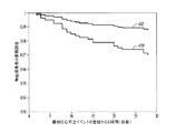
図4は、ある患者が心不全患者として最初に登録された時から始まる、急性心不全イベントを経験しなかった患者集団の割合のグラフの例を示している。患者は、S3心音の振幅の高い測定値を有する患者と、S3心音の振幅の低い測定値を有する患者とに分けられた。このグラフは、低S3振幅を有する患者(グラフ405)の方が高S3振幅を有する患者(グラフ410)よりも無症候(event−free)である割合が高いことを示している。よって、このグラフは、急性心不全のリスクを評価するためにS3の振幅を用いることができることを示している。 FIG. 4 shows an example graph of the percentage of the patient population that did not experience an acute heart failure event, starting from when a patient was first enrolled as a heart failure patient. Patients were divided into patients with high S3 heart sound amplitude measurements and patients with low S3 heart sound amplitude measurements. This graph shows that patients with low S3 amplitude (graph 405) are more asymptomatic (patient-graph) than patients with high S3 amplitude (graph 410). Thus, this graph shows that the amplitude of S3 can be used to assess the risk of acute heart failure.
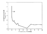
図5は、患者集団のS3エネルギーデータの回帰モデルからのp値のグラフ505の例を示している。横軸は、患者に対して急性心不全のリスクを評価するために用いられたS3エネルギーデータの日数を表わしている。前記グラフにおいて、1日以上にわたって平均されたS3エネルギー測定値は、S3エネルギー測定値が1日未満のデータについて平均されたときよりも低いp値を生じた。より低いp値ほどリスクデータのより良好な分離に対応する。よって、複数日わたってデータを平均することにより、急性心不全のリスクのより良好な評価が提供される。図5の例では、グラフ505は、5日以上からのデータが用いられたときにp値が安定することを示している。
FIG. 5 shows an example of a p-
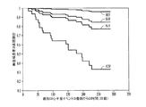
図3の方法によって求めた定量化リスクは、その後の数分間、その後の1時間、又は同日のその後の間に起こる急性心不全イベントのリスクではなく、むしろより長期間(例えば1〜12か月)にわたって心不全イベントを経験する対象者のリスクの現れである。図6は、S3心音のエネルギーに基づいた患者集団のリスク指標を用いる例を示す。前記図は、患者の心不全患者としての最初の登録時から始まる、急性心不全イベントを経験しなかった患者集団の割合を示している。前記患者は、S3心音エネルギーの高い測定値を有
する患者と、S3心音エネルギーの低い測定値を有する患者とに分けられた。前記グラフは、心不全患者として登録した時と登録後6か月以降との間において、急性心不全イベントを経験した低S3エネルギー群の割合と、急性心不全イベントを経験した高S3エネルギー群との割合との間で強い分離を示している。
The quantification risk determined by the method of FIG. 3 is not the risk of an acute heart failure event occurring during the next few minutes, the next hour, or the same day, but rather a longer period (eg, 1-12 months) It is a manifestation of the risk of subjects who experience heart failure events over time. FIG. 6 shows an example using the risk index of the patient population based on the energy of the S3 heart sound. The figure shows the percentage of the patient population that did not experience an acute heart failure event, starting from the first enrollment of the patient as a heart failure patient. The patients were divided into patients with high S3 heart sound energy measurements and patients with low S3 heart sound energy measurements. The graph shows the proportion of the low S3 energy group that experienced an acute heart failure event and the proportion of the high S3 energy group that experienced an acute heart failure event between when enrolling as a heart failure patient and after 6 months after enrollment. Shows a strong separation between.
より長期におけるリスクの評価は、すべての心不全患者に対して高い標準治療を維持しながら、心不全を監視及び治療するために、より良好な資源の配分を可能にし得る。例えば、患者に対する中心傾向測定値がリスク基準を満たす場合には、患者は高リスクとして分類され、その患者にはより多くの監視資源が割り当てられ得る。患者に対する中心傾向測定値がリスク基準を満たさない場合には、患者は低リスクとして分類され、それに応じて資源が割り当てられ得る。 Longer-term risk assessment may allow better resource allocation to monitor and treat heart failure while maintaining a high standard of care for all heart failure patients. For example, if the central trend measure for a patient meets the risk criteria, the patient is classified as high risk and the patient can be assigned more monitoring resources. If the central trend measure for the patient does not meet the risk criteria, the patient can be classified as low risk and resources can be allocated accordingly.
ブロック330において、求めた中心傾向測定値が急性心不全のリスクを示す基準を満たす場合には表示が生成され得る。前記表示は、医師又は介護者に対して表示装置上で対象者のリスクカテゴリを提示する警告を含み得る。前記表示はプログラミング装置又はサーバ上で実行するプロセスに提供され得る。対象者に対する経過観察予定は、前記表示に従って自動的に調整される(例えば、経過観察通院(follow−up visits)をより頻繁にすることができる)か、又は医師又は介護者による選択のために提案される経過観察予定が示され得る。
In
図7は、対象者に対する急性心不全のリスクを評価する携行型医療装置700の例の一部のブロック図を示している。装置700は、少なくとも、第1の生理学的センサー回路705と、生理学的センサー回路705に通信可能に接続された制御回路710とを備える。生理学的センサー回路705と制御回路710との間には介在する回路構成が存在し得るが、前記通信可能な接続は、生理学的センサー回路705と通信回路710との間で通信される電気信号を提供する。
FIG. 7 shows a block diagram of a portion of an example of a portable
生理学的センサー回路705は、対象者の心臓血管機能を表す第1の生理学的信号と、制御回路710とを生成することができる。生理学的センサー回路の一例は本願において前述した心音センサー回路である。生理学的なセンサー回路705の別の例は呼吸センサー回路である。呼吸センサー回路は、対象者についての呼吸情報を含む呼吸信号を生成することができる。前記呼吸信号は、対象者の呼吸の吸気体積又は流量、呼気体積又は流量、呼吸数又はタイミング、又は任意の組み合わせ、置換又は構成要素のような対象者の呼吸を示す任意の信号を含み得る。呼吸センサー回路は、加速度計、インピーダンスセンサー、体積又は流量センサー及び圧力センサーのうちの1つ以上のような植込み型センサーを含み得る。
The
生理学的センサー回路705のさらに別の例は心臓信号センサー回路である。心臓信号センサー回路は、対象者の電気的な心臓活動を表す心臓活動信号を生成する。心臓信号センサー回路の一例としては、1つ以上の電極に接続可能な1つ以上のセンス増幅器が挙げられる。生理学的センサー回路705のさらに別の例はバイオマーカーセンサー回路である。本願において前述したように、バイオマーカーセンサー回路は、対象者におけるバイオマーカーの濃度を表すバイオマーカー信号を生成する。
Yet another example of the
制御回路710は、ソフトウェアモジュール又はファームウェアモジュール内の命令を解釈又は実行するマイクロプロセッサ、デジタルシグナルプロセッサ、特定用途向け集積回路(ASIC)又は他のタイプのプロセッサを備え得る。制御回路710は、記載した前記機能を実行するために他の回路又はサブ回路を備え得る。これらの回路は、ソフトウェア、ハードウェア、ファームウェア又はそれらの任意の組み合わせを含み得る。複数の機能は、回路及びサブ回路の1つ以上において所望通りに実行され得る。
The
制御回路710は、(例えばプログラムすることによって、かつ/又は論理回路によって)第1の生理学的センサー信号を用いて第1の生理学的測定値を求めるように構成された信号処理回路715を含む。本願において前述したように、生理学的センサー回路705が心音センサー回路を含む場合には、第1の生理学的測定値は、ポストS2心音エネルギーの測定値を含み得る。前記測定値は、ポストS2心音エネルギーの振幅、強度、及び出力のうちの1つ以上を含み得る。特定の例において、前記測定値は、S3心音エネルギー及びS4心音エネルギーのうちの1つ以上の測定値を含む。
The
信号処理回路715は、第1所定期間(例えば複数日)にわって生理学的センサー回路705によって生成された複数の生理学的信号を用いて、複数の生理学的測定値を求めることができる。次に、信号処理回路715は、複数の生理学的測定値を用いて生理学的測定値の中心傾向を求める。
The
制御回路710はまた、求めた中心傾向測定値を用いて、対象者に対する急性心不全のリスクを定量化するリスク回路720も含み得る。いくつかの例において、急性心不全のリスクの定量は、求めた中心傾向測定値を急性心不全のリスクを示す1つ以上の基準と比較することを含む。いくつかの例において、前記基準は、対象者のリスクカテゴリを求める1つ以上の閾値との比較を含む。例えば、リスク回路720は、S3心音エネルギーの中心傾向測定値を第1のS3心音エネルギー閾値と比較し得る。前記中心傾向測定値が第1のS3心音エネルギー閾値を満たさない場合には、その対象者は低リスクカテゴリに配され得る。前記中心傾向測定値が第1のS3心音エネルギー閾値を満たす場合には、その対象者はより高いリスクカテゴリに配され得る。
The
前記リスクを定量化するためにより多くのカテゴリを用いることができる。例えば、第1のS3心音エネルギー閾値と、第2のS3心音エネルギー閾値とを用いることができ、前記第2閾値は第1閾値よりも高い。前記S3中心傾向測定値が第1のS3心音エネルギー閾値又は第2のS3心音エネルギー閾値のいずれも満たさない場合には、その対象者は低リスクカテゴリに配され得る。前記S3中心傾向測定値が第1のS3心音エネルギー閾値を満たすが、第2のS3心音エネルギー閾値は満たさない場合には、その対象者は中リスクカテゴリに配され、前記S3中心傾向測定値が第2のS3心音エネルギー閾値を満たす場合には、その対象者は高リスクカテゴリに配され得る。拡大すると、より多くのカテゴリを用いることができ、対象者は求めた中心傾向測定値に従ってリスクカテゴリに配される。 More categories can be used to quantify the risk. For example, a first S3 heart sound energy threshold and a second S3 heart sound energy threshold can be used, and the second threshold is higher than the first threshold. If the S3 central trend measurement does not satisfy either the first S3 heart sound energy threshold or the second S3 heart sound energy threshold, the subject may be placed in a low risk category. If the S3-centric trend measurement value meets the first S3 heart sound energy threshold but does not meet the second S3 heart sound energy threshold, the subject is placed in the middle risk category, and the S3-centric trend measurement value is If the second S3 heart sound energy threshold is met, the subject may be placed in a high risk category. When expanded, more categories can be used, and the subject is placed in the risk category according to the determined central trend measure.
いくつかの例において、リスク回路720は、対象者に対するリスク指標を生成することによって急性心不全リスクを定量化する。前記リスク指標は、対象者の急性心不全のリスクを低リスク、中リスク、高リスクとして分類することを含み得る。前記リスク指標は、リスクをリスク四分位数(quartile)、十分位数(decile)、五分位数(quintile)などに従って分類することを含み得る。前記リスク指標は、急性心不全イベントのリスクを示す連続値であり得る(例えば、対象者に対するリスク指標を0.0〜1.0の連続スケール上の値による確率として計算する)。前記リスク指標は生理学的センサー信号の生の測定値(とりわけ、S3心音の振幅の生の測定値、呼吸数変動の生の測定値、対象者中に存在するバイオマーカーの濃度の生の測定値、及び1つ以上の生理学的信号において検知されるフィーチャの間の時間間隔の生の測定値など)であり得る。
In some examples, the
本願において前述したように、リスク回路720は求めた中心傾向測定値を第1のリスク検知閾値と比較してもよい。前記リスク指標は、求めた中心傾向測定値が所定期間内に第1リスク検知閾値を満たす回数(例えば頻度)の計数であり得る。リスク回路720は
、例えば予定に従って(毎日、毎週、毎月、又は一時間毎に)、前記リスク指標を回帰的に求めてもよい。前記リスク指標に従って通知が生成されてもよい。
As described above in the present application, the
前記リスク指標を生成するために用いられる急性心不全のリスクを示す基準(例えば閾値中心傾向測定値)は、例えば6か月間又は12か月間のような所定期間にわたって起こる急性心不全イベントのリスクを定量化するために(例えばプログラム値又は通信値として)規定され得る。リスク基準は、いったん装置700において規定されたら固定されてもよいし、又はリスク回路720は急性心不全のリスクを示す1つ以上の基準を調整するアルゴリズムを回帰的に実行してもよい。例えば、リスク回路720は、患者固有データ(例えば生理学的データ及びイベント履歴データのうちの一方又は双方)に基づいてリスク基準を調整してもよい。いくつかの例において、前記閾値は、ユーザーによってプログラム可能であり得る(例えば、医師の選択に従って、又は対象者に固有のデータに従ってプログラムされる)。
Criteria indicating the risk of acute heart failure used to generate the risk index (eg, threshold-centric trend measure) quantifies the risk of an acute heart failure event that occurs over a predetermined period of time, eg, 6 months or 12 months To be defined (eg, as a program value or a communication value). The risk criteria may be fixed once defined in the
制御回路710は、リスク回路720によって定量されたリスクの表示を生成することができる。例えば、制御回路710は、求めたリスク指標に基づいて高リスクの表示を生成し得る。装置700が着用型装置に備えられている場合、前記表示は、例えば警告を表示することによって、リスクの警告をユーザーに提示するために用いられ得る。
The
装置700は、別体の装置と信号を通信する通信回路725を備え得る。前記通信は、無線(例えばRF遠隔測定)又は有線(例えばユニバーサルシリアルバス)のインターフェースを介し得る。前記リスクの表示は、高リスクの警告が表示もしくは通信される別体の装置上のプロセスに通信されてもよいし、又はリスクのレベルが前記プロセスに通信され得る。いくつかの例において、別体の装置(例えばサーバ)は、前記リスクの表示に基づいて対象者の経過観察通院の予定を調整してもよい。いくつかの例において、リスクの定量化は別体の装置によって行われる。例えば、リスク回路720は別体の装置に備えられてもよく、装置700は、リスクが定量化される別体の装置に測定値を通信する。
一部の例において、いくつかの予備信号処理は、生理学的センサー信号において、その信号が中心傾向測定値を求めるために用いられる前に実施され得る。例えば、第1の生理学的センサー回路705は第1の生理学的センサー信号タイプを生成し得る。信号処理回路715は、複数の心周期について得られた第1の生理学的センサー信号タイプの複数の信号を用いて、中心傾向信号(例えばアンサンブル平均)を求め得る。信号処理回路715は、複数の中心傾向信号を用いて生理学的測定値を求め(例えば、ポストS2心音エネルギーの大きさが心音信号のアンサンブル平均から得られる)、中心傾向測定値は複数の生理学的測定値を用いて得られる。上述したように、中心傾向信号は、30秒のような短期間にわたって求められるか、又は8〜10心周期から得られた信号を用いて求められる。前記中心傾向測定値は、一日以上の期間に得られた測定値を用いて計算される。リスクの定量化は、次の数か月から約1年のうちに急性心不全を経験する対象者のリスクを評価するために用いられる。
In some examples, some preliminary signal processing may be performed on a physiological sensor signal before the signal is used to determine a central trend measurement. For example, the first
前記中心傾向測定値のいくつかの例としては、ポストS2心音エネルギーの中心傾向測定値、S3心音エネルギーの中心傾向測定値、呼吸数の中心傾向測定値、呼吸数の変動の中心傾向測定値、対象者において検知されたバイオマーカーの濃度の中心傾向測定値、1つ以上の生理学的センサー信号中の基準フィーチャ間の時間間隔の中心傾向測定値、及び時間間隔の中心傾向測定値の比が挙げられる。測定値の組み合わせもまた急性心不全のリスクを評価するのに有用であり得る。 Some examples of the central tendency measurement value include a central tendency measurement value of post-S2 heart sound energy, a central tendency measurement value of S3 heart sound energy, a central tendency measurement value of respiratory rate, a central tendency measurement value of fluctuation of respiratory rate, A central trend measurement of the concentration of a biomarker detected in the subject, a central trend measurement of the time interval between reference features in one or more physiological sensor signals, and a ratio of the central trend measurement of the time interval. It is done. A combination of measurements may also be useful for assessing the risk of acute heart failure.
いくつかの例によれば、心不全イベントに対するリスクの評価は、ポストS2心音エネルギーの中心傾向測定値及び呼吸数の中心傾向測定値の双方を用いて行うことができる。
第1の生理学的センサー回路705は心音センサー回路を含み、かつ装置700は呼吸センサー回路を含む第2生理学的センサー回路を備える。信号処理回路715は、複数の心音信号を用いて、複数のポストS2心音エネルギーの測定値を求め、複数の呼吸信号を用いて、複数の呼吸数の測定値を求める。次に、前記信号処理回路は、ポストS2心音エネルギーの中心傾向測定値及び呼吸数の中心傾向測定値を求める。前記リスク回路は、前記呼吸数の中心傾向測定値とポストS2心音エネルギーの中心傾向測定値とを用いて、対象者に対する急性心不全のリスクを定量化する。特定の例において、前記ポストS2心音エネルギーの中心傾向測定値は、S3エネルギーの中心傾向測定値を含み得る。また前記呼吸数の中心傾向測定値は、呼吸数の変動の測定値の中心傾向を含み得る。
According to some examples, the risk assessment for a heart failure event can be performed using both a central trend measurement of post S2 heart sound energy and a central trend measurement of respiratory rate.
The first
図8は、S3エネルギー及び呼吸数(RR)変動に基づくリスク指標の例を示す。前記図面は、低S3エネルギー及び低呼吸数変動が測定された患者に対する無症候患者の割合のグラフ805、低S3エネルギー及び高呼吸数変動が測定された患者に対する無症候患者の割合のグラフ810、高S3エネルギー及び低呼吸数変動が測定された患者に対する無症候患者の割合のグラフ815、及び高S3エネルギー及び高呼吸数変動が測定された患者に対する無症候患者の割合のグラフ820を示している。低S3エネルギー及び低呼吸数変動が測定された患者は低リスク群に配され、高S3エネルギー及び高呼吸数変動が測定された患者は高リスク群に配され得る。残りの患者は中リスク群に配され得る。中心傾向測定値が低いか、又は高いかの判定は、前記測定値の測定閾値との比較を含み得る。急性心不全のリスクの表示は、リスク評価の表示、患者の経過観察予定の変更のうちの1つ以上において用いることができる。低リスク群、中リスク群及び高リスク群により、異なる3レベルの応答が生成され得る。
FIG. 8 shows an example of a risk index based on S3 energy and respiratory rate (RR) fluctuations. The figure shows a
心不全イベントのリスクを評価するために、リスクを判定するための他のグループ化(例えば4つの個々のリスク群)を用いることができる。センサーを融合させる他の方法も用いることができる。例えば、S3エネルギーは、リスク指標を求める際に呼吸数変動とは異なる重みを与えられてもよい。 Other groupings for determining risk (eg, four individual risk groups) can be used to assess the risk of heart failure events. Other methods of fusing the sensors can also be used. For example, the S3 energy may be given a weight different from the respiratory rate variation when determining the risk index.
急性心不全のリスクを定量化するために、心音信号からの他の測定値を用いることができる。例えば、心音信号の2つの基準フィーチャ間で測定される時間間隔は、ポストS2心音エネルギー及び呼吸数の中心傾向測定値の1つ以上と組み合わせて用いることができる。いくつかの例において、信号処理回路715は、心音信号の2つの基準フィーチャ間の時間間隔と、複数の心音信号を用いて複数の前記時間間隔とを求める。信号処理回路705は前記時間間隔の中心傾向測定値を求め、前記リスク回路は、前記時間間隔の中心傾向測定値を用い、かつ呼吸数の中心傾向測定値及びポストS2心音エネルギーの中心傾向測定値のうちの少なくとも一方を用いて、対象者に対する急性心不全のリスクを定量化する。
Other measurements from the heart sound signal can be used to quantify the risk of acute heart failure. For example, a time interval measured between two reference features of a heart sound signal can be used in combination with one or more of post S2 heart sound energy and respiratory rate central trend measurements. In some examples, the
いくつかの例において、前記時間間隔は、S1心音を示す第1基準フィーチャと、S2心音を示す第2基準フィーチャとの間において測定される。リスク回路720は、S1心音とS2心音との間で測定された複数の時間間隔の中心傾向測定値を用いて、かつ呼吸数の中心傾向測定値及びポストS2心音エネルギーの中心傾向測定値の少なくとも一方を用いて、対象者に対する急性心不全のリスクを定量化する。
In some examples, the time interval is measured between a first reference feature indicative of an S1 heart sound and a second reference feature indicative of an S2 heart sound. The
センサーデータの他のグループ化を用いることができる。例えば、感知した心臓活動信号の2つの基準フィーチャ間において測定された時間間隔は、ポストS2心音エネルギー及び呼吸数の中心傾向測定値のうちの1つ以上と組み合わせて用いられ得る。第1の生理学的センサー回路705は、心音センサー回路又は呼吸センサー回路の少なくとも一方を含み得る。装置700は、心臓信号センサー回路を含む第2生理学的センサー回路を備えてもよい。信号処理回路715は、心臓活動信号中の2つの基準フィーチャ間の時間間隔
を測定し、複数の心臓活動信号を用いて、複数の前記時間間隔の測定値を求める。信号処理回路715は、複数の前記時間間隔の測定値を用いて、中心傾向時間間隔を求める。信号処理回路715はまた、中心傾向ポストS2心音エネルギー測定値又は中心傾向呼吸数測定値の少なくとも一方を生成する。リスク回路720は、前記中心傾向時間間隔と、中心傾向ポストS2心音エネルギー測定値又は中心傾向呼吸数測定値のうちの少なくとも一方とを用いて、対象者に対する急性心不全のリスクを定量化する。
Other groupings of sensor data can be used. For example, the time interval measured between two reference features of the sensed cardiac activity signal can be used in combination with one or more of post S2 heart sound energy and respiratory rate central trend measurements. The first
いくつかの例において、前記心臓活動信号中の基準フィーチャはR波であり、前記心臓活動信号における時間間隔は第1R波から第2R波までの時間間隔を含む。リスク回路720は、測定されたR波−R波時間間隔の中心傾向と、中心傾向ポストS2心音エネルギー測定値又は中心傾向呼吸数測定値の少なくとも一方とを用いて、対象者に対する急性心不全のリスクを定量化する。
In some examples, the reference feature in the cardiac activity signal is an R wave, and the time interval in the cardiac activity signal includes a time interval from a first R wave to a second R wave. The
別のセンサーデータのグループ化において、感知した心臓活動信号の少なくとも1つの基準フィーチャと感知した心音信号の少なくとも1つの基準フィーチャとの間で測定される時間間隔を、ポストS2心音エネルギー及び呼吸数の中心傾向測定値のうちの1つ以上と組み合わせて用いることができる。第1の生理学的センサー回路705は心音センサー回路を含むことができ、かつ装置700は呼吸センサー回路を含む第2生理学的センサー回路と、心臓信号センサー回路を含む第3生理学的センサー回路とを備える。
In another sensor data grouping, the time interval measured between at least one reference feature of the sensed cardiac activity signal and at least one reference feature of the sensed heart sound signal is calculated as a post S2 heart sound energy and respiratory rate. Can be used in combination with one or more of the central tendency measurements. The first
信号処理回路715は、心臓活動信号中の基準フィーチャと心音信号中の基準フィーチャとの間における時間間隔を測定し、複数の心臓活動信号及び心音信号を用いて、複数の前記時間間隔の測定値を求める。信号処理回路705は、複数の時間間隔測定値を用いて、中心傾向時間間隔を測定し、複数の心音信号から得られた複数のポストS2心音エネルギーを用いてポストS2心音エネルギーの中心傾向測定値、又は複数の呼吸信号から得られた複数の呼吸数測定値を用いて呼吸数の中心傾向測定値のうちの少なくとも一方を求める。リスク回路720は、前記中心傾向時間間隔と、前記中心傾向ポストS2心音エネルギー測定値又は中心傾向呼吸数測定値のうちの少なくとも一方とを用いて、対象者に対する急性心不全のリスクを定量化する。
The
心臓活動信号中の基準フィーチャと心音信号中の基準フィーチャとの間の時間間隔は、i)R波とS1心音との間の時間間隔、ii)Q波とS1心音との間の時間間隔、iii)R波と大動脈弁の開放(Ao)を表す基準との間の時間間隔、iv)Q波とAoを表す基準との間の時間間隔、又はv)Aoを表す基準フィーチャと、大動脈弁の閉鎖(Ac)を表す基準フィーチャとの間の時間間隔のうちの少なくとも1つを含み得る。 The time interval between the reference feature in the heart activity signal and the reference feature in the heart sound signal is i) the time interval between the R wave and the S1 heart sound, ii) the time interval between the Q wave and the S1 heart sound, iii) the time interval between the R wave and the reference representing the aortic valve opening (Ao), iv) the time interval between the Q wave and the reference representing Ao, or v) the reference feature representing Ao and the aortic valve May include at least one of the time intervals between the reference feature representing the closure (Ac).
時間間隔の比を用いることができる。信号処理回路715は、前記時間間隔のうちの2つの中心傾向を求め、それらの中心傾向測定値の比を求め得る。
別のセンサーデータのグループ化では、急性心不全のリスクを評価するために、ポストS2心音エネルギーの大きさ、呼吸数の大きさ、又は時間間隔の大きさのうちの少なくとも1つと組み合わせて、対象者中に存在するバイオマーカーの濃度の大きさが用いられ得る。第1の生理学的センサー回路705は、心音センサー回路、呼吸センサー回路又は心臓信号センサー回路のうちの少なくとも1つを含む。装置700は、バイオマーカーセンサー回路を含む第2生理学的センサー回路を備える。
A ratio of time intervals can be used. The
In another sensor data grouping, in order to assess the risk of acute heart failure, in combination with at least one of post S2 heart sound energy magnitude, respiratory rate magnitude, or time interval magnitude, The magnitude of the concentration of the biomarker present therein can be used. The first
信号処理回路715は、複数のバイオマーカー信号を用いて、対象者におけるバイオマーカーの濃度の複数の表示を求め、そのバイオマーカーの濃度の複数の表示を用いて、バイオマーカー濃度の表示の中心傾向を生成する。信号処理回路715はまた、中心傾向ポストS2心音エネルギー測定値、中心傾向呼吸数測定値、心音信号中の2つの基準フィーチャ間の時間間隔の中心傾向測定値、心臓活動信号中の2つの基準フィーチャ間の時間間
隔の中心傾向測定値、又は心臓信号中の基準フィーチャと心音信号中の基準フィーチャとの間の時間間隔の中心傾向測定値のうちの少なくとも1つも生成する。
The
リスク回路720は、前記バイオマーカー濃度の表示の中心傾向と、中心傾向ポストS2心音エネルギー測定値、中心傾向呼吸数測定値、心音信号中の2つの基準フィーチャ間の時間間隔の中心傾向測定値、心臓活動信号中の2つの基準フィーチャ間の時間間隔の中心傾向測定値、又は心臓信号中の基準フィーチャと心音信号中の基準フィーチャとの間の時間間隔の中心傾向測定値のうちの少なくとも1つとを用いて、対象者に対する急性心不全のリスクを定量化する。
The
いくつかの例によれば、心不全イベントのリスクの評価において、心不全履歴データを用いることができる。リスク回路720は、求めた中心傾向測定値(例えばポストS2心音エネルギーの中心傾向測定値)を用いて、かつ対象者の心不全入院の履歴データを用いて、対象者に対する急性心不全のリスクを定量化する。いくつかの例において、急性心不全のリスクを示す基準は、求めた中心傾向測定値に対する第1リスク検知閾値を含み得る。リスク回路720は、対象者についての生理学的データ及び心不全入院の履歴データの一方又は双方に従って第1リスク検知閾値を調整することができる。前記履歴データは、制御回路710に一体化されているか、又は制御回路710に接続されたメモリ内に格納されていてもよいし、又は前記履歴データは別体の装置に格納されていてもよい。
According to some examples, heart failure history data can be used in assessing the risk of a heart failure event. The
図9は、S3エネルギー及び心不全入院の履歴を用いて求めたリスク指標の例を示している。心不全入院は、患者が、病院内で、又は外来患者として、心不全に対する治療を受けたかどうかを表している。いくつかの例において、患者が最近6か月間に少なくとも1回の治療を受けたか、又は最近12か月間に少なくとも2回の治療を受けたならば、心不全入院は正又は真となり得る。前記図面は、低S3エネルギーの大きさを有し、かつその履歴に心不全入院がない患者に対する無症候患者の割合のグラフ905、低S3エネルギーの大きさを有し、その履歴に心不全入院がある患者に対する無症候患者の割合のグラフ910、高S3エネルギーの大きさを有し、かつその履歴に心不全入院がない患者に対する無症候患者の割合のグラフ915、及び高S3エネルギーの大きさを有し、かつその履歴に心不全入院がある患者に対する無症候患者の割合のグラフ920を示している。低S3エネルギーを有し、かつ心不全入院履歴がない患者は、低リスク群に配され、高S3エネルギーを有し、かつ心不全入院履歴がある患者は高リスク群に配され得る。残りの患者は、中リスク群に配されて、生じた反応の3つのレベルを形成し得るか、又は他の患者は低リスク群に配されてもよい。対象者履歴が心不全入院のいくつかのエピソードを有する場合には、リスク回路720は、評価の感度を増大させるように、1つ以上のリスク検知閾値を調整し得る。同様に、対象者履歴が心不全入院の少数のエピソードを有するか、又はそのようなエピソードを含まない場合には、リスク回路720は、評価の感度を低下させるように、1つ以上のリスク検知閾値を調整し得る。
FIG. 9 shows an example of the risk index obtained using the S3 energy and the history of heart failure hospitalization. Heart failure hospitalization represents whether the patient has been treated for heart failure in the hospital or as an outpatient. In some instances, heart failure hospitalization can be positive or true if the patient has received at least one treatment in the last 6 months or at least two treatments in the last 12 months. The figure is a
他の例としては、心不全入院履歴、並びに、呼吸数の中心傾向測定値及び心不全入院履歴、バイオマーカー濃度の中心傾向測定値及び心不全入院履歴、1つ以上の生理学的信号の基準フィーチャ間の時間間隔の中心傾向測定値のうちの少なくとも1つを用いて、又はポストS2心音エネルギー、呼吸数、バイオマーカー濃度及び時間間隔の任意の組み合わせを用いて、リスクを評価することが挙げられる。 Other examples include heart failure hospitalization history, and central trend measurements of respiratory rate and heart failure hospitalization history, central trend measurements of biomarker concentrations and heart failure hospitalization history, time between reference features of one or more physiological signals Assessing risk using at least one of the central trend measurements of the interval, or using any combination of post S2 heart sound energy, respiratory rate, biomarker concentration and time interval.
これらのいくつかの装置及び方法の例は、対象者の生理学的イベントの監視が、その対象者が将来に心不全の悪化を経験するリスクを予測するのに有用であり得ることを示している。これは、患者の心不全を監視及び治療するための医療資源の効率的な配分を可能にする。 Some of these examples of devices and methods show that monitoring a subject's physiological events may be useful in predicting the risk that the subject will experience worsening heart failure in the future. This allows for an efficient allocation of medical resources to monitor and treat the patient's heart failure.
附記及び実施例
実施例1は、少なくとも、対象者の心臓血管機能を表す第1の生理学的信号を生成するように構成された第1の生理学的センサー回路と、その第1の生理学的センサー回路に通信可能に接続された制御回路とを備える主題(装置、デバイス又はシステムなど)を含むか、又は使用することができる。前記制御回路は信号処理回路とリスク回路とを含む。前記信号処理回路は、第1の生理学的センサー信号を用いて第1の生理学的測定値を求め、第1所定期間にわたって生成される複数の第1の生理学的信号を用いて複数の第1の生理学的測定値を求め、複数の生理学的測定値の中心傾向測定値を求めるように構成されている。前記リスク回路は、求めた中心傾向測定値を用いて、対象者に対する急性心不全(WHF)のリスクを定量化するように構成されており、前記リスクの定量は、求めた中心傾向測定値を、急性心不全のリスクを示す1つ以上の基準と比較することを含む。前記制御回路は、前記中心傾向測定値が前記急性心不全のリスクを示す1つ以上の基準を満たす場合に警告を生成するように構成されている。
Appendix and Examples Example 1 is a first physiological sensor circuit configured to generate at least a first physiological signal representative of a subject's cardiovascular function, and the first physiological sensor circuit. Including or using a subject matter (such as an apparatus, device or system) comprising a control circuit communicatively coupled to the device. The control circuit includes a signal processing circuit and a risk circuit. The signal processing circuit uses a first physiological sensor signal to determine a first physiological measurement and uses a plurality of first physiological signals generated over a first predetermined time period to generate a plurality of first physiological signals. A physiological measurement is determined and a central trend measurement of the plurality of physiological measurements is determined. The risk circuit is configured to quantify the risk of acute heart failure (WHF) for a subject using the determined central tendency measurement value, and the quantification of the risk includes the determined central tendency measurement value, Comparing to one or more criteria indicating the risk of acute heart failure. The control circuit is configured to generate an alert if the central trend measurement meets one or more criteria indicative of the risk of acute heart failure.
実施例2は、第1の生理学的信号タイプを生成するように構成された第1の生理学的センサー回路と、複数の心周期について得られた第1の生理学的センサー信号タイプの複数の信号を用いて第1の中心傾向信号を生成し、その第1の中心傾向信号を用いて第1の生理学的測定値を求めるように任意で構成された信号処理回路とを備え得るか、又はそれらを備えるように任意で実施例1の主題と組み合わせられ得る。 Example 2 includes a first physiological sensor circuit configured to generate a first physiological signal type and a plurality of signals of a first physiological sensor signal type obtained for a plurality of cardiac cycles. And a signal processing circuit optionally configured to generate a first central trend signal and to determine a first physiological measurement using the first central trend signal, or Optionally, it can be combined with the subject matter of Example 1 to provide.
実施例3は、複数日を含む第1所定期間を含み得るか、又はそれを含むように任意で実施例1及び実施例2のうちの1つ又は任意の組み合わせの主題と組み合わせられ得る。
実施例4は、対象者の心臓の機械的活動を表す心音信号を生成するように構成された心音センサー回路を含む生理学的センサー回路を備え得るか、又はそれを備えるように任意で実施例1乃至3のうちの1つ又は任意の組み合わせの主題と組み合わせられ得る。前記信号処理回路は、任意で、前記心音信号を用いてポストS2心音エネルギーの測定値と、複数の心音信号を用いて複数のポストS2心音エネルギーの測定値とを求めて、ポストS2心音エネルギーの中心傾向測定値を求めるように構成され得る。前記リスク回路は、任意で、前記ポストS2心音エネルギーの中心傾向測定値を用いて、対象者に対する急性心不全のリスクを定量化するように構成され得る。
Example 3 may include a first predetermined time period that includes multiple days, or may optionally be combined with the subject matter of one or any combination of Example 1 and Example 2 to include it.
Example 4 may comprise or optionally include a physiological sensor circuit including a heart sound sensor circuit configured to generate a heart sound signal representative of the mechanical activity of the subject's heart. 1 to 3 or any combination of themes can be combined. The signal processing circuit optionally calculates a post S2 heart sound energy measurement value using the heart sound signal and a plurality of post S2 heart sound energy measurement values using a plurality of heart sound signals, It may be configured to determine a central trend measure. The risk circuit may optionally be configured to quantify the risk of acute heart failure for the subject using the central trend measurement of the post S2 heart sound energy.
実施例5は、対象者の呼吸を表す呼吸信号を生成するように構成された呼吸センサー回路を含む生理学的センサー回路を備え得るか、又はそれを備えるように任意で実施例4の主題と組み合わせられ得る。前記信号処理回路は、任意で、前記呼吸信号を用いて呼吸数の測定値と、複数の呼吸信号を用いて複数の呼吸数の測定値とを求めて、呼吸数の中心傾向測定値を求めるように構成され得る。前記リスク回路は、任意で、前記呼吸数の中心傾向測定値とポストS2心音エネルギーの中心傾向測定値とを用いて、対象者に対する急性心不全のリスクを定量化するように構成され得る。 Example 5 may comprise or optionally be combined with the subject matter of Example 4 to include a physiological sensor circuit that includes a respiration sensor circuit configured to generate a respiration signal representative of the subject's respiration. Can be. The signal processing circuit optionally calculates a respiratory rate measurement using the respiratory signal and a plurality of respiratory measurement using a plurality of respiratory signals to determine a central tendency measurement of the respiratory rate. Can be configured as follows. The risk circuit may optionally be configured to quantify the risk of acute heart failure for the subject using the central trend measure of respiratory rate and the central trend measure of post S2 heart sound energy.
実施例6は、前記複数の呼吸数の測定値を用いて、呼吸数の変動を求めるように構成された信号処理回路と、前記呼吸数の変動とポストS2心音エネルギーの中心傾向測定値とを用いて、対象者に対する急性心不全のリスクを定量化するように構成されたリスク回路とを備え得るか、又はそれらを備えるように実施例5の主題と任意で組み合わせられ得る。 In the sixth embodiment, a signal processing circuit configured to obtain a change in respiration rate using the plurality of respiration rate measurements, and a central tendency measurement value of the respiration rate change and post S2 heart sound energy are obtained. Used to comprise a risk circuit configured to quantify the risk of acute heart failure for a subject, or optionally combined with the subject matter of Example 5 to comprise them.
実施例7は、前記心音信号を用いてS3心音エネルギーの測定値と、複数の心音信号を用いてS3心音エネルギーの複数の測定値とを求めて、S3心音エネルギーの中心傾向測定値を求めるように構成された信号処理回路を備え得るか、又はそれを備えるように実施例4乃至6のうちの1つ又は任意の組み合わせの主題と任意で組み合わせられ得る。前記リスク回路は、任意で、S3心音エネルギーの中心傾向測定値を用いて、対象者に対する
急性心不全のリスクを定量化するように構成され得る。
In the seventh embodiment, a measured value of the S3 heart sound energy is obtained using the heart sound signal, and a plurality of measured values of the S3 heart sound energy are obtained using a plurality of heart sound signals, thereby obtaining a central tendency measured value of the S3 heart sound energy. Or may be optionally combined with one or any combination of the subject matter of Examples 4-6 to provide it. The risk circuit may optionally be configured to quantify the risk of acute heart failure for the subject using a central trend measure of S3 heart sound energy.
実施例8は、対象者の心臓の機械的活動を表す心音信号を生成するように構成された心音センサー回路を含む第1の生理学的センサー回路と、対象者の呼吸を表す呼吸信号を生成するように構成された呼吸センサー回路を含む第2生理学的センサー回路と、対象者の電気的な心臓活動を表す心臓活動信号を生成するように構成された心臓信号センサー回路を含む第3生理学的センサー回路とを備え得るか、又はそれらを備えるように任意で実施例1乃至3のうちの1つ又は任意の組み合わせの主題と組み合わせられ得る。前記信号処理回路は、任意で、複数の心音信号を用いて複数のポストS2心音エネルギーの測定値、又は複数の呼吸信号を用いて複数の呼吸数の測定値のうちの少なくとも一方を求め、中心傾向ポストS2心音エネルギー測定値又は中心傾向呼吸数測定値の少なくとも一方を生成し、心臓活動信号中の少なくとも1つの基準フィーチャと、心音信号中の少なくとも1つの基準フィーチャとの間の1つ以上の時間間隔を測定し、複数の心臓活動信号及び心音信号を用いて、複数の前記時間間隔の測定値を求め、前記時間間隔の複数の測定値を用いて、中心傾向時間間隔又は前記時間間隔の比の中心傾向の少なくとも一方を求めるように構成され得る。前記リスク回路は、任意で、中心傾向時間間隔と、中心傾向ポストS2心音エネルギー測定値又は中心傾向呼吸数測定値のうちの少なくとも一方とを用いて、対象者に対する急性心不全のリスクを定量化するように構成され得る。 Example 8 generates a first physiological sensor circuit that includes a heart sound sensor circuit configured to generate a heart sound signal representative of the mechanical activity of the subject's heart and a respiratory signal representative of the subject's respiration. A second physiological sensor circuit including a respiration sensor circuit configured as described above and a third physiological sensor including a cardiac signal sensor circuit configured to generate a cardiac activity signal representative of the subject's electrical heart activity A circuit, or optionally combined with the subject matter of one or any combination of examples 1-3. The signal processing circuit optionally obtains at least one of a plurality of post-S2 heart sound energy measurement values using a plurality of heart sound signals or a plurality of respiration rate measurement values using a plurality of respiration signals, One or more of a trend post S2 heart sound energy measurement or a central trend respiratory rate measurement is generated, and at least one reference feature in the heart activity signal and at least one reference feature in the heart sound signal Measuring a time interval, obtaining a plurality of measured values of the time interval using a plurality of cardiac activity signals and heart sound signals, and using a plurality of measured values of the time interval to determine a central trend time interval or the time interval It may be configured to determine at least one of the central trends of the ratio. The risk circuit optionally quantifies the risk of acute heart failure for the subject using a central trend time interval and at least one of a central trend post S2 heart sound energy measurement or a central trend respiratory rate measurement. Can be configured as follows.
実施例9は、R波とS1心音との間の時間間隔、Q波とS1心音との間の時間間隔、R波とR波との間の時間間隔、Q波とQ波との間の時間間隔、S1心音とS2心音の間の時間間隔、R波とS2心音との間の時間間隔、Q波とS2心音との間の時間間隔、R波と大動脈弁の開放(Ao)を表す基準との間の時間間隔、Q波とAoを表す基準との間の時間間隔、又はAoを表す基準フィーチャと大動脈弁(Ac)の閉鎖を表す基準フィーチャと間の時間間隔のうちの少なくとも1つを含み得る、心臓活動信号中の少なくとも1つの基準フィーチャと心音信号中の少なくとも1つの基準フィーチャとの間において測定される時間間隔を含み得るか、又はそれを含むように実施例8の主題と任意で組み合わせられ得る。 Example 9 shows a time interval between the R wave and the S1 heart sound, a time interval between the Q wave and the S1 heart sound, a time interval between the R wave and the R wave, and a time interval between the Q wave and the Q wave. Time interval, time interval between S1 heart sound and S2 heart sound, time interval between R wave and S2 heart sound, time interval between Q wave and S2 heart sound, R wave and aortic valve opening (Ao) At least one of the time interval between the reference, the time interval between the Q wave and the reference representing Ao, or the time interval between the reference feature representing Ao and the reference feature representing closure of the aortic valve (Ac). Subject matter of Example 8 to include or include a time interval measured between at least one reference feature in the heart activity signal and at least one reference feature in the heart sound signal And can be combined arbitrarily.
実施例10は、対象者の心臓の室の機械的作動を表す心音信号を生成するように構成された心音センサー回路、対象者の呼吸を表す呼吸信号を生成するように構成された呼吸センサー回路、又は対象者の電気的な心臓活動を表す心臓信号を生成するように構成された心臓信号センサー回路のうちの少なくとも1つを含む第1の生理学的センサー回路と、対象者におけるバイオマーカーの濃度を表すバイオマーカー信号を生成するように構成されたバイオマーカーセンサー回路を含む第2生理学的センサー回路とを備え得るか、又はそれらを備えるように実施例1乃至3のうちの1つ又は任意の組み合わせの主題と任意で組み合わせられ得る。前記信号処理回路は、任意で、複数の心音信号を用いて複数のポストS2心音エネルギーの測定値、複数の呼吸信号を用いて複数の呼吸数の測定値、心音信号中の2つの基準フィーチャ間の時間間隔の複数の測定値、心臓活動信号中の2つの基準フィーチャ間の時間間隔の複数の測定値、又は心臓信号中の基準フィーチャと心音信号中の基準フィーチャとの間の時間間隔の複数の測定値のうちの少なくとも1つを求めるように構成され得る。前記信号処理回路は、任意で、中心傾向ポストS2心音エネルギー測定値、中心傾向呼吸数測定値、心音信号中の2つの基準フィーチャ間の時間間隔の中心傾向測定値、心臓活動信号中の2つの基準フィーチャ間の時間間隔の中心傾向測定値、又は心臓信号中の基準フィーチャと心音信号中の基準フィーチャとの間の時間間隔の中心傾向測定値のうちの少なくとも1つを生成するように構成され得る。前記信号処理回路は、任意で、複数のバイオマーカー信号を用いて、対象者のバイオマーカーの濃度の複数の表示を求め、そのバイオマーカーの濃度の複数の表示を用いて、バイオマーカー濃度の表示の中心傾向を生成するように構成され得る。前記リスク回路は、任意で、前記バイオマーカー濃度の表示の中心傾向と、中心傾向ポストS2心音エネルギー測定値、中心傾向呼吸数測定
値、心音信号中の2つの基準フィーチャ間の時間間隔の中心傾向測定値、心臓活動信号中の2つの基準フィーチャ間の時間間隔の中心傾向測定値、又は心臓信号中の基準フィーチャと心音信号中の基準フィーチャとの間の時間間隔の中心傾向測定値のうちの少なくとも1つとを用いて、対象者に対する急性心不全のリスクを定量化するように構成され得る。
Example 10 is a heart sound sensor circuit configured to generate a heart sound signal representative of mechanical operation of a subject's heart chamber, and a respiratory sensor circuit configured to generate a breath signal representative of the subject's respiration. A first physiological sensor circuit comprising at least one of a cardiac signal sensor circuit configured to generate a cardiac signal representative of the subject's electrical heart activity, and a biomarker concentration in the subject A second physiological sensor circuit comprising a biomarker sensor circuit configured to generate a biomarker signal representative of or one or any combination of examples 1-3 to include them Can be arbitrarily combined with the subject matter. The signal processing circuit optionally includes a plurality of post S2 heart sound energy measurements using a plurality of heart sound signals, a plurality of respiration rate measurements using a plurality of respiration signals, and between two reference features in the heart sound signal. Multiple measurements of time intervals, multiple measurements of time intervals between two reference features in a heart activity signal, or multiple time intervals between reference features in a heart signal and reference features in a heart sound signal May be configured to determine at least one of the measured values. The signal processing circuit optionally includes a central trend post S2 heart sound energy measurement, a central trend respiratory rate measurement, a central trend measurement of a time interval between two reference features in the heart sound signal, and two in the heart activity signal. Configured to generate at least one of a central trend measurement of a time interval between reference features or a central trend measurement of a time interval between a reference feature in a heart signal and a reference feature in a heart sound signal. obtain. The signal processing circuit optionally obtains a plurality of indications of a subject's biomarker concentration using a plurality of biomarker signals, and uses the plurality of indications of the biomarker concentration to display a biomarker concentration. May be configured to generate a central tendency of. The risk circuit optionally includes a central trend of the display of the biomarker concentration, a central trend of a central trend post S2 heart sound energy measurement, a central trend respiratory rate measurement, and a time interval between two reference features in the heart sound signal. Of the measured value, the central trend measurement of the time interval between two reference features in the heart activity signal, or the central trend measurement of the time interval between the reference feature in the heart signal and the reference feature in the heart sound signal The at least one can be used to quantify the risk of acute heart failure for the subject.
実施例11は、対象者中のB型ナトリウム利尿ペプチド(BNP)の濃度、又は対象者のNT−Pro−BNPの濃度のうちの少なくとも一方を表すバイオマーカー信号を生成するように構成されたバイオマーカーセンサー回路を備え得るか、又はそれを備えるように実施例10の主題と任意で組み合わせられ得る。 Example 11 is a biomer configured to generate a biomarker signal representative of at least one of a concentration of B-type natriuretic peptide (BNP) in a subject or a concentration of NT-Pro-BNP in a subject A car sensor circuit may be provided, or optionally combined with the subject matter of Example 10 to provide it.
実施例12は、求めた中心傾向測定値を用い、かつ対象者についての心不全入院の履歴データを用いて、対象者に対する急性心不全のリスクを定量化するように構成されたリスク回路を備え得るか、又はそれを備えるように実施例1乃至11のうちの1つ又は任意の組み合わせの主題と任意で組み合わせられ得る。 Example 12 may comprise a risk circuit configured to quantify the risk of acute heart failure for a subject using the determined central trend measure and using historical heart failure hospitalization data for the subject Or any combination with the subject matter of one or any combination of Examples 1-11 to provide it.
実施例13は、求めた中心傾向測定値を第1リスク検知閾値と比較し、求めた中心傾向測定値が所定期間内に第1リスク検知閾値を満たす頻度に従って、急性心不全に対するリスク指標を求めるように構成されたリスク回路を備え得るか、又はそれを備えるように実施例1乃至12のうちの1つ又は任意の組み合わせの主題と任意で組み合わせられ得、前記制御回路はそのリスク指標に従って警告を生成するように構成されている。 Example 13 compares the obtained central tendency measurement value with the first risk detection threshold value, and obtains a risk index for acute heart failure according to the frequency with which the obtained central tendency measurement value satisfies the first risk detection threshold value within a predetermined period. A risk circuit configured as follows, or optionally combined with one or any combination of themes of Examples 1 to 12 to provide it, the control circuit alerting according to its risk indicator Configured to generate.
実施例14は、求めた中心傾向測定値に対する第1リスク検知閾値を含む急性心不全のリスクを示す基準と、対象者についての生理学的データ及び心不全入院の履歴データの一方又は双方に従って第1リスク検知閾値を調整するように任意で構成されたリスク回路を備え得るか、又はそれを備えるように実施例1乃至13のうちの1つ又は任意の組み合わせの主題と任意で組み合わせられ得る。 Example 14 provides a first risk detection according to a criterion indicating a risk of acute heart failure including a first risk detection threshold for a determined central trend measurement and one or both of physiological data and history data of heart failure hospitalization for the subject. A risk circuit optionally configured to adjust the threshold may be provided, or optionally combined with one or any combination of themes of Examples 1-13 to provide it.
実施例15は、対象者に対する急性心不全のリスクを回帰的に定量し、急性心不全のリスクを示すための1つ以上の基準を回帰的に調整するように構成されたリスク回路を備え得るか、又はそれを備えるように実施例1乃至14の1つ又は任意の組み合わせの主題と任意で組み合わせられ得る。 Example 15 may comprise a risk circuit configured to recursively quantify the risk of acute heart failure for a subject and recursively adjust one or more criteria for indicating the risk of acute heart failure, Alternatively, it can optionally be combined with one or any combination of themes of Examples 1-14 to provide it.
実施例16は、携行型医療装置の第1の生理学的センサーを用いて、心臓血管機能を表す第1の生理学的センサー信号を生成することと、第1の生理学的センサー信号を用いて、第1の生理学的測定値を求めることと、第1所定期間にわたって複数の第1の生理学的センサー信号を生成することと、複数の第1の生理学的センサー信号を用いて、複数の生理学的測定値を求めることと、前記複数の生理学的測定値の中心傾向測定値を求めることと、求めた中心傾向測定値を用いて、対象者に対する急性心不全のリスクを定量化することとを含む主題(例えば、装置、行為を実施するための手段、又は機械によって実行されたときに、その機械に行為を実施させる指示を含む機械可読媒体を操作する方法など)を含み得るか、又はそれを含むように実施例1乃至15の1つ又は任意の組み合わせの主題と任意で組み合わせられ得る。急性心不全のリスクの定量は、任意で、求めた中心傾向測定値を、急性心不全のリスクを示す1つ以上の基準と比較することを含み得る。前記主題は、任意で、求めた中心傾向測定値が急性心不全のリスクを示す基準を満たす場合に、装置によって警告を生成することを含み得る。 Example 16 uses a first physiological sensor of the portable medical device to generate a first physiological sensor signal representative of cardiovascular function, and uses the first physiological sensor signal to Determining a single physiological measurement, generating a plurality of first physiological sensor signals over a first predetermined period of time, and using the plurality of first physiological sensor signals to generate a plurality of physiological measurements. Determining a central trend measurement of the plurality of physiological measurements, and using the determined central trend measurement to quantify the risk of acute heart failure for the subject (e.g., , A device, a means for performing an action, or a method for operating a machine-readable medium that includes instructions that, when executed by a machine, cause the machine to perform the action). It may be combined in the subject and any one or any combination of Examples 1 to 15. Quantifying the risk of acute heart failure may optionally include comparing the determined central trend measure to one or more criteria indicative of the risk of acute heart failure. The subject matter may optionally include generating an alert by the device if the determined central trend measurement meets a criterion indicative of risk of acute heart failure.
実施例17は、複数の心音信号を生成することと、前記複数の心音信号を用いて複数のポストS2心音エネルギーの測定値を求めることと、ポストS2心音エネルギーの中心傾向測定値を求めることと、前記ポストS2心音エネルギーの中心傾向測定値を用いて、対象者に対する急性心不全のリスクを定量化することとを含み得るか、又はそれらを含むよ
うに実施例16の主題と任意で組み合わせられ得る。
Example 17 generates a plurality of heart sound signals, obtains a plurality of post S2 heart sound energy measurements using the plurality of heart sound signals, and obtains a central tendency measurement of the post S2 heart sound energy. , Using the central trend measure of post S2 heart sound energy, or quantifying the risk of acute heart failure for a subject, or optionally combined with the subject matter of Example 16 to include them. .
実施例18は、呼吸センサー回路を用いて複数の呼吸信号を生成することと、前記複数の呼吸信号を用いて複数の呼吸数の測定値を求めることと、前記複数の呼吸数の測定値を用いて、呼吸数の中心傾向測定値を求めることと、前記ポストS2心音エネルギーの中心傾向測定値と、呼吸数の中心傾向測定値とを用いて、対象者に対する急性心不全のリスクを定量化することとを含み得るか、又はそれらを含むように実施例16乃至17の1つ又は任意の組み合わせの主題と任意で組み合わせられ得る。 In Example 18, a plurality of respiration signals are generated using a respiration sensor circuit, a plurality of respiration rate measurements are obtained using the respiration signals, and a plurality of respiration rate measurements are obtained. And using the post-S2 heart sound energy central tendency measurement value and the respiratory rate central tendency measurement value to quantify the risk of acute heart failure for the subject. Or can be optionally combined with the subject matter of one or any combination of Examples 16-17 to include them.
実施例19は、複数の心音信号又は複数の呼吸信号のうちの少なくとも一方を生成することと、心音信号は対象者の心臓の機械的活動を表しており、呼吸信号は対象者の呼吸を表すことと、複数のポストS2心音エネルギーの測定値又は複数の呼吸数の測定値のうちの少なくとも一方を求めることと、中心傾向ポストS2心音エネルギー測定値又は中心傾向呼吸数測定値の少なくとも一方を求めることを含む、中心傾向測定値を求めることと、複数の心臓活動信号を生成することと、心臓活動信号は対象者の電気的な心臓活動を表すことと、心音信号中の少なくとも1つの基準フィーチャと心臓活動信号中の少なくとも1つの基準フィーチャとの間の時間間隔の複数の測定値を求めることと、心音信号中の少なくとも1つの基準フィーチャと心臓活動信号中の少なくとも1つの基準フィーチャとの間の時間間隔の中心傾向測定値を求めることとを含み得るか、又はそれらを含むように実施例16の主題と任意で組み合わせられ得る。前記主題は任意で、前記時間間隔の中心傾向測定値と、前記中心傾向ポストS2心音エネルギー測定値又は中心傾向呼吸数測定値のうちの少なくとも一方とを用いて、対象者に対する急性心不全のリスクを定量化することを含む。 Example 19 generates at least one of a plurality of heart sound signals or a plurality of respiration signals, and the heart sound signal represents the subject's heart mechanical activity, and the respiration signal represents the respiration of the subject And determining at least one of a plurality of post S2 heart sound energy measurements or a plurality of respiratory rate measurements, and determining at least one of a central tendency post S2 heart sound energy measurement value or a central tendency respiratory rate measurement value. Determining a central trend measurement, generating a plurality of cardiac activity signals, the cardiac activity signal representing an electrical heart activity of the subject, and at least one reference feature in the heart sound signal Determining a plurality of measurements of a time interval between and at least one reference feature in the heart activity signal; and at least one reference feature in the heart sound signal; Which may include either a determining the central tendency measurement of the time interval between at least one reference feature in the organ activity signal, or may be combined in the subject with any of Examples 16 to include them. The subject matter is optional and uses the central trend measurement of the time interval and at least one of the central trend post S2 heart sound energy measurement or central trend respiratory rate measurement to reduce the risk of acute heart failure to the subject. Including quantification.
実施例20は、対象者についての心不全入院の履歴データを格納することと、求めた中心傾向測定値と対象者についての心不全入院の履歴データとを用いて、対象者に対する急性心不全のリスクを定量化することとを含み得るか、又は含むために実施例16乃至19の1つ又は任意の組み合わせの主題と任意で組み合わせられ得る。 Example 20 quantifies the risk of acute heart failure for a subject by storing historical data on heart failure hospitalization for the subject, and using the determined central tendency measurements and history data for heart failure hospitalization for the subject. Or can be optionally combined with the subject matter of one or any combination of Examples 16-19 to include.
実施例21は、実施例1乃至20の機能のいずれか1つ以上を実行するための手段か、又は機械によって実行されたときに、前記機械に実施例1乃至20の機能のいずれか1つ以上を実行させる指示を含む機械可読媒体を備え得る主題を含むか、又はそれを含むように実施例1乃至20のいずれか1つ以上の任意の部分又は任意の部分の組み合わせと任意で組み合わせられ得る。 Example 21 is a means for performing any one or more of the functions of Examples 1-20, or when performed by a machine, the machine has any one of the functions of Examples 1-20. The subject matter can be provided with a machine-readable medium containing instructions to perform the above, or can be optionally combined with any one or more arbitrary portions or combinations of arbitrary portions of Examples 1-20 to include it obtain.
上記の詳細な説明は、該詳細な説明の一部を形成する添付図面への言及を含む。前記図面は、例証として、本発明が実施され得る特定の実施形態を示している。これらの実施形態はまた本願では「実施例」とも称される。本文書と、参照により援用された文書との間で用法が一致しない場合には、援用された参考文献における用法は、本文書のそれに対する補足であると考えられるべきであり、相容れない矛盾については本文書における用法が支配する。 The above detailed description includes references to the accompanying drawings, which form a part of the detailed description. The drawings show, by way of illustration, specific embodiments in which the invention can be practiced. These embodiments are also referred to herein as “examples”. If the usage does not match between this document and the document incorporated by reference, the usage in the incorporated reference should be considered as a supplement to that of this document, for inconsistent conflicts The usage in this document dominates.
本文書において、用語「a」又は「an」は、特許文献において一般的であるように、「少なくとも1つ(at least one)」又は「1つ以上(one or more)」の任意の他の例又は用法とは無関係に、1つ又は2つ以上を含むように用いられる。この文書において、用語「又は」は、別段の指示がない限り、「A又はB」が、「AだがBではない」、「BだがAではない」、及び「A及びB」を含むように、非排他的論理和を示すために用いられる。添付する請求項において、用語「備える(including)」及び「前記〜において(in which)」は、「備える(comprising)」及び「前記〜において(wherein)」という各用語の平易な英語の同意義
として用いられる。また、以下の請求項において、用語「備える(including)」及び「備える(comprising)」は非制限的であり、すなわち、請求項においてそのような用語の後に列記されたものに加えて要素を含むシステム、装置、物品又はプロセスは、依然としてその請求項の範囲内にあると見なされる。さらに、以下の請求項において、用語「第1」、「第2」、及び「第3」などは、単に標識として用いられており、それらの対象に対して数的な要件を課するようには意図されない。
In this document, the terms “a” or “an” are used in the patent literature to refer to any “at least one” or any one or more of “one or more”. Regardless of the example or usage, it is used to include one or more. In this document, the term “or”, unless otherwise indicated, “A or B” includes “A but not B”, “B but not A”, and “A and B”. , Used to indicate non-exclusive OR. In the appended claims, the terms “including” and “in which” mean the plain English equivalents of the terms “comprising” and “wherein”. Used as Also, in the following claims, the terms “including” and “comprising” are non-limiting, that is, include elements in addition to those listed after such terms in the claims. The system, apparatus, article or process is still considered to be within the scope of the claims. Further, in the following claims, the terms “first”, “second”, “third”, etc. are used merely as labels and impose numerical requirements on their objects. Is not intended.
本願に記載した方法の例は、少なくとも一部分において、機械によって実施されるか、又はコンピューターによって実施され得る。いくつかの例としては、上記の例に記載したような方法を行うために電子デバイスを構成するように作動可能な命令によってコード化されたコンピューター可読媒体又は機械可読媒体が挙げられる。そのような方法の実施は、マイクロコード、アセンブリ言語コード、高水準言語コードなどのようなコードを含み得る。そのようなコードは、様々な方法を行うためのコンピューター可読命令を含み得る。前記コードは、コンピュータプログラム製品の一部を形成し得る。さらに、前記コードは、実行の間に、又は他の時に、1つ以上の揮発性又は不揮発性のコンピューター可読媒体上に具体的に格納され得る。これらのコンピューター可読媒体としては、ハードディスク、リムーバル磁気ディスク、リムーバル光ディスク(例えばコンパクトディスク及びデジタルビデオディスク)、磁気カセット、メモリーカード又はメモリースティック、ランダムアクセスメモリー(RAM)、読出し専用メモリー(ROM)などを挙げることができるが、これらに限定されるものではない。いくつかの例において、キャリア媒体は、前記方法を実施するコードを保持することができる。用語「キャリア媒体」はコードが伝送される搬送波を表わすために用いられ得る。 The example methods described herein can be machine-implemented or computer-implemented, at least in part. Some examples include computer readable media or machine readable media encoded with instructions operable to configure an electronic device to perform the methods as described in the examples above. Implementation of such a method may include code such as microcode, assembly language code, high level language code, and the like. Such code may include computer readable instructions for performing various methods. The code may form part of a computer program product. Further, the code may be specifically stored on one or more volatile or non-volatile computer readable media during execution or at other times. These computer readable media include hard disks, removable magnetic disks, removable optical disks (eg, compact disks and digital video disks), magnetic cassettes, memory cards or memory sticks, random access memory (RAM), read only memory (ROM), and the like. However, it is not limited to these. In some examples, the carrier medium may carry code that performs the method. The term “carrier medium” may be used to denote the carrier on which the code is transmitted.
上記の説明は、例示であり、限定的なものではないことが意図される。例えば、上述の例(又はそれらの1つ以上の態様)は互いに組み合わせて用いてもよい。上記の説明の検討により、当業者などによって、他の実施形態が用いられ得る。要約書は、読者が技術的な開示の性質を迅速に確認できるようにするために、米国特許法施行規則第1.72条(b)に準拠するために提供される。要約書は、特許請求の範囲又は意味を解釈又は限定するためには用いられないという理解で提出されている。また、上記の詳細な説明において、様々な特徴は開示を簡素化するためにグループ化され得る。これは、権利請求されていない開示された特徴が任意の請求項に対して必須であることを意図していると解釈されるべきでない。むしろ、本発明の主題は、特定の開示された実施形態のすべての特徴よりも少ない状態にあってもよい。したがって、以下の特許請求の範囲は、これにより詳細な説明に援用され、各請求項は別個の実施形態として自立している。本発明の範囲は、添付の特許請求の範囲、並びに係る特許請求の範囲が権利を享受する均等物の全範囲を参照して決定されるべきである。 The above description is intended to be illustrative and not restrictive. For example, the above-described examples (or one or more aspects thereof) may be used in combination with each other. Other embodiments may be used by those skilled in the art upon review of the above description. The abstract is provided to comply with 37 CFR 1.72 (b) so that the reader can quickly ascertain the nature of the technical disclosure. It is submitted with the understanding that it will not be used to interpret or limit the scope or meaning of the claims. Also, in the above detailed description, various features may be grouped to simplify the disclosure. This should not be interpreted as intending that an unclaimed disclosed feature is essential to any claim. Rather, the subject matter of the invention may be less than all the features of a particular disclosed embodiment. Thus, the following claims are hereby incorporated into the detailed description, with each claim standing on its own as a separate embodiment. The scope of the invention should be determined with reference to the appended claims, along with the full scope of equivalents to which such claims are entitled.
Claims (16)
前記心音センサー回路に通信可能に接続された制御回路とを備える装置において、前記制御回路は、
所定の期間にわたって生成された複数の心音信号を用いて複数のポストS2心音エネルギーの測定値を求め、及び、前記ポストS2心音エネルギーの測定値の中心傾向測定値を求めるための信号処理回路と、
求めた中心傾向測定値を用いて、急性心不全のリスクカテゴリを割り当てることによって対象者に対する前記急性心不全のリスクを定量化するためのリスク回路とを含んでなる、装置。 A heart sound sensor circuit for generating a heart sound signal indicative of the cardiovascular function of the Target Company,
And a control circuit communicatively connected to the heart sound sensor circuit, wherein the control circuit comprises:
It obtains a measurement of a plurality of posts S2 heart sound energy by using a plurality of heart sound signals generated over between Jo Tokoro periods, and a signal processing circuit for obtaining the central tendency measurement values of the post S2 heart sound energy When,
Using central tendency measurements obtained, ing and a risk circuit for quantifying the risk of the acute heart failure for a subject by assigning risk categories of acute heart failure, device.
複数の心周期について得られた前記ポストS2心音エネルギーの複数の前記測定値を用いて、前記中心傾向測定値を求める、請求項1に記載の装置。 Before Symbol signal processing circuit,
Using a plurality of the measurement values of the plurality of obtained for cardiac cycle the post S2 heart sound energy device according to the central tendency measurements determined Mel, to claim 1.
前記信号処理回路は、
複数の呼吸信号を用いて複数の呼吸数の測定値を求めて、
前記複数の呼吸数の測定値を用いて呼吸数の中心傾向測定値を求め、
前記リスク回路は、求めた前記呼吸数の中心傾向測定値とポストS2心音エネルギーの中心傾向測定値とを用いて、対象者に対する急性心不全のリスクを定量化する、請求項1に記載の装置。 Comprising a respiratory sensor circuitry configured to generate a respiration signal representing the respiration of the subject,
The signal processing circuit includes:
Seeking a measurement of a plurality of respiratory rate using the respiratory signal of multiple,
Using the plurality of respiratory rate measurements to determine a central trend measure of respiratory rate,
The risk circuit uses a central tendency measured value of the respiration rate of the central tendency measurements and post-S2 heart sound energy calculated, to quantify the risk of acute heart failure for subjects, according to claim 1.
前記信号処理回路は、複数の呼吸信号を用いて複数の呼吸数の測定値を求めて、前記複数の呼吸数の測定値を用いて呼吸数の変動を求め、
前記リスク回路は、前記呼吸数の変動とポストS2心音エネルギーの中心傾向測定値とを用いて、対象者に対する急性心不全のリスクを定量化する、請求項1に記載の装置。 A respiration sensor circuit configured to generate a respiration signal representative of the subject's respiration;
The signal processing circuit obtains a plurality of respiration rate measurements using a plurality of respiration signals, obtains a change in respiration rate using the plurality of respiration rate measurements,
The apparatus of claim 1 , wherein the risk circuit quantifies the risk of acute heart failure for a subject using the respiratory rate variation and a central trend measure of post S2 heart sound energy.
前記所定の期間にわたって生成された複数の心音信号を用いて前記ポストS2心音エネルギーとしてS3心音エネルギーの複数の測定値を求めて、
S3心音エネルギーの中心傾向測定値を求め、
前記リスク回路は、前記S3心音エネルギーの中心傾向測定値を用いて、対象者に対する急性心不全のリスクを定量化する、請求項1に記載の装置。 The signal processing circuit includes:
Obtaining a plurality of measured values of S3 heart sound energy as the post S2 heart sound energy using a plurality of heart sound signals generated over the predetermined period ;
Find the central trend measurement of S3 heart sound energy,
The apparatus of claim 1 , wherein the risk circuit quantifies the risk of acute heart failure for a subject using the central trend measurement of the S3 heart sound energy.
前記信号処理回路は、
心臓活動信号中の少なくとも1つの基準フィーチャと、心音信号中の少なくとも1つの基準フィーチャとの間の1つ以上の時間間隔を測定し、複数の心臓活動信号及び心音信号を用いて、複数の前記時間間隔の測定値を求め、
前記複数の時間間隔の測定値を用いて、中心傾向時間間隔又は時間間隔の比の中心傾向の少なくとも一方を求め、
前記リスク回路は、前記中心傾向時間間隔と、ポストS2心音エネルギー測定値の中心傾向とを用いて、対象者に対する急性心不全のリスクを定量化する、請求項1に記載の装置。 Comprising a cardiac signal sensor circuits for generating a cardiac activity signal representative of the electrical heart activity of the Target Company,
The signal processing circuit includes:
Measuring one or more time intervals between at least one reference feature in the heart activity signal and at least one reference feature in the heart sound signal, and using a plurality of heart activity signals and heart sound signals, Find the time interval measurement,
Using the measured values of the plurality of time intervals to determine at least one of the central tendency time interval or the central tendency of the ratio of the time intervals,
The risk circuit comprises a central tendency time interval, by using the central tendency of the post S2 heart sound energy measurements to quantify the risk of acute heart failure for subjects, according to claim 1.
R波とS1心音との間の時間間隔、
Q波とS1心音との間の時間間隔、
R波とR波との間の時間間隔、
Q波とQ波との間の時間間隔、
S1心音とS2心音との間の時間間隔、
R波とS2心音との間の時間間隔、
Q波とS2心音との間の時間間隔、
R波と大動脈弁の開放(Ao)を表す基準との間の時間間隔、
Q波とAoを表す基準との間の時間間隔、又は、
Aoを表す基準フィーチャと大動脈弁の閉鎖(Ac)を表す基準フィーチャと間の時間間隔のうちの少なくとも1つを含む、請求項8に記載の装置。 The time interval between at least one reference feature in the cardiac activity signal and at least one reference feature in the heart sound signal is:
The time interval between the R wave and the S1 heartbeat,
The time interval between the Q wave and the S1 heart sound,
The time interval between the R and R waves,
The time interval between Q wave and Q wave,
The time interval between the S1 heart sound and the S2 heart sound,
The time interval between the R wave and the S2 heart sound,
The time interval between the Q wave and the S2 heart sound,
The time interval between the R wave and the reference representing the opening of the aortic valve (Ao),
The time interval between the Q wave and the reference representing Ao, or
9. The apparatus of claim 8, comprising at least one of a time interval between a reference feature representing Ao and a reference feature representing aortic valve closure (Ac).
対象者の電気的な心臓活動を表す心臓信号を生成する心臓信号センサー回路のうちの少なくとも1つを含み、
前記信号処理回路は、
複数の呼吸信号を用いた複数の呼吸数の測定値と、心音信号中の2つの基準フィーチャ間の時間間隔の複数の測定値と、心臓活動信号中の2つの基準フィーチャ間の時間間隔の複数の測定値と、心臓信号中の基準フィーチャと心音信号中の基準フィーチャとの間の時間間隔の複数の測定値とからなる群のうちの少なくとも1つを求め、
呼吸数の中心傾向測定値と、心音信号中の2つの基準フィーチャ間の時間間隔の中心傾向測定値と、心臓活動信号中の2つの基準フィーチャ間の時間間隔の中心傾向測定値と、心臓信号中の基準フィーチャと心音信号中の基準フィーチャとの間の時間間隔の中心傾向測定値とからなる群のうちの少なくとも1つを生成し、
前記リスク回路は、前記ポストS2心音エネルギー強度と、前記呼吸数の中心傾向測定値、心音信号中の2つの基準フィーチャ間の時間間隔の中心傾向測定値、心臓活動信号中の2つの基準フィーチャ間の時間間隔の中心傾向測定値、及び心臓信号中の基準フィーチャと心音信号中の基準フィーチャとの間の時間間隔の中心傾向測定値とからなる群のうちの少なくとも1つとを用いて前記リスクを定量化する、
請求項1に記載の装置。 A respiration sensor circuit that generates a respiration signal representative of the subject's respiration, or
Seen at least Tsuo含of cardiac signal sensor circuit for generating a cardiac signal representing electrical heart activity in a subject,
The signal processing circuit includes:
Multiple respiratory rate measurements using multiple respiratory signals, multiple measurements of time intervals between two reference features in a heart sound signal, and multiple time intervals between two reference features in a heart activity signal And at least one of a group consisting of a plurality of measurements of a time interval between a reference feature in the heart signal and a reference feature in the heart sound signal,
A central trend measure of respiratory rate, a central trend measure of a time interval between two reference features in a heart sound signal, a central trend measure of a time interval between two reference features in a cardiac activity signal, and a cardiac signal Generating at least one of the group consisting of a central trend measure of a time interval between the reference feature in the heart signal and the reference feature in the heart sound signal;
The risk circuit includes the post S2 heart sound energy intensity, the central trend measurement of the respiratory rate, the central trend measurement of the time interval between two reference features in the heart sound signal, and the two reference features in the heart activity signal. And at least one of the group consisting of: a central trend measurement of a time interval of time and a central trend measurement of a time interval between a reference feature in a heart signal and a reference feature in a heart sound signal. To quantify,
The apparatus of claim 1.
前記信号処理回路は、
複数のバイオマーカー信号を用いて、対象者のバイオマーカーの濃度の複数の表示を求め、
前記バイオマーカーの濃度の複数の表示を用いて、バイオマーカー濃度の表示の中心傾向を生成し、
前記リスク回路は、前記バイオマーカー濃度の表示の中心傾向と、前記ポストS2心音エネルギーの中心傾向測定値とを用いて、対象者に対する急性心不全のリスクを定量化する、請求項10に記載の装置。 The device comprises a biomarker sensor circuitry for generating a biomarker signal representative of the concentration of biomarkers in a subject,
The signal processing circuit includes:
Using multiple biomarker signals, determine multiple indications of the subject's biomarker concentration,
Using a plurality of indications of the biomarker concentration, generating a central tendency for the indication of the biomarker concentration;
The risk circuit includes a central tendency display of the biomarker concentrations, and have use the central tendency measurements of the post S2 heart sound energy, to quantify the risk of acute heart failure for subjects, according to claim 10 apparatus.
対象者中のB型ナトリウム利尿ペプチド(BNP)の濃度、又は、
対象者のNT−Pro−B型ナトリウム利尿ペプチドの濃度のうちの少なくとも一方を表すバイオマーカー信号を生成する、請求項11に記載の装置。 The biomarker sensor circuit is
The concentration of B-type natriuretic peptide (BNP) in the subject, or
12. The device of claim 11, wherein the device generates a biomarker signal representative of at least one of the concentration of the subject's NT-Pro-B type natriuretic peptide.
求めた中心傾向測定値が所定期間内に急性心不全の第1リスク検知閾値を満たす頻度に従って、急性心不全に対するリスク指標を求め、前記制御回路は前記リスク指標に従って警告を生成する、請求項1に記載の装置。 The risk circuit compares the determined central tendency measurement with a first risk detection threshold;
2. The risk index for acute heart failure is determined according to a frequency at which the determined central tendency measurement value satisfies a first risk detection threshold value for acute heart failure within a predetermined period, and the control circuit generates a warning according to the risk index. Equipment.
Applications Claiming Priority (5)
| Application Number | Priority Date | Filing Date | Title |
|---|---|---|---|
| US201261676679P | 2012-07-27 | 2012-07-27 | |
| US61/676,679 | 2012-07-27 | ||
| US201361768821P | 2013-02-25 | 2013-02-25 | |
| US61/768,821 | 2013-02-25 | ||
| PCT/US2013/044680 WO2014018165A1 (en) | 2012-07-27 | 2013-06-07 | Heart failure patients stratification |
Publications (3)
| Publication Number | Publication Date |
|---|---|
| JP2015529488A JP2015529488A (en) | 2015-10-08 |
| JP2015529488A5 JP2015529488A5 (en) | 2016-07-21 |
| JP6283670B2 true JP6283670B2 (en) | 2018-02-21 |
Family
ID=48741505
Family Applications (1)
| Application Number | Title | Priority Date | Filing Date |
|---|---|---|---|
| JP2015524260A Active JP6283670B2 (en) | 2012-07-27 | 2013-06-07 | Stratification of patients with heart failure |
Country Status (5)
| Country | Link |
|---|---|
| US (1) | US20140031643A1 (en) |
| EP (1) | EP2877086A1 (en) |
| JP (1) | JP6283670B2 (en) |
| CN (2) | CN104661588B (en) |
| WO (1) | WO2014018165A1 (en) |
Cited By (1)
| Publication number | Priority date | Publication date | Assignee | Title |
|---|---|---|---|---|
| US11615891B2 (en) | 2017-04-29 | 2023-03-28 | Cardiac Pacemakers, Inc. | Heart failure event rate assessment |
Families Citing this family (17)
| Publication number | Priority date | Publication date | Assignee | Title |
|---|---|---|---|---|
| US9968266B2 (en) | 2006-12-27 | 2018-05-15 | Cardiac Pacemakers, Inc. | Risk stratification based heart failure detection algorithm |
| US9830801B2 (en) * | 2013-11-20 | 2017-11-28 | Medical Informatics Corp. | Alarm management system |
| US10978208B2 (en) | 2013-12-05 | 2021-04-13 | International Business Machines Corporation | Patient risk stratification by combining knowledge-driven and data-driven insights |
| CN106132286B (en) | 2014-03-07 | 2020-04-21 | 心脏起搏器股份公司 | Multi-stage heart failure event detection |
| CN106470598B (en) * | 2014-07-01 | 2020-03-10 | 心脏起搏器股份公司 | System for detecting medical treatment |
| CN104706373B (en) * | 2015-02-04 | 2017-02-15 | 四川长虹电器股份有限公司 | Heart vital index calculating method based on heart sounds |
| US10368774B2 (en) * | 2015-07-30 | 2019-08-06 | Medtronic, Inc. | Absolute intrathoracic impedance based scheme to stratify patients for risk of a heart failure event |
| WO2017059202A1 (en) * | 2015-10-02 | 2017-04-06 | Cardiac Pacemakers, Inc. | Predictions of worsening heart failure |
| US10660577B2 (en) | 2016-04-01 | 2020-05-26 | Cardiac Pacamakers, Inc. | Systems and methods for detecting worsening heart failure |
| CN109475341A (en) * | 2016-07-14 | 2019-03-15 | 康廷尤斯生物测定有限公司 | The system and method for remote probe for heart |
| US10863948B2 (en) | 2017-12-06 | 2020-12-15 | Cardiac Pacemakers, Inc. | Heart failure stratification based on respiratory pattern |
| KR102471671B1 (en) * | 2018-02-21 | 2022-11-29 | 삼성전자주식회사 | Electronic device and method for providing information regarding cardiovascular state of user |
| CN108324268A (en) * | 2018-02-26 | 2018-07-27 | 河南善仁医疗科技有限公司 | A kind of analysis method of electrocardiogram caardiophonogram |
| CN109171684A (en) * | 2018-08-30 | 2019-01-11 | 上海师范大学 | A kind of automatic health monitor system based on wearable sensors and smart home |
| US11359011B2 (en) | 2019-08-07 | 2022-06-14 | Edifice Health, Inc. | Treatment and prevention of cardiovascular disease |
| CN111755125B (en) * | 2020-07-07 | 2024-04-23 | 医渡云(北京)技术有限公司 | Method, device, medium and electronic equipment for analyzing patient measurement index |
| US20230301601A1 (en) | 2022-03-25 | 2023-09-28 | Cardiac Pacemakers, Inc. | Systems and methods to predict mortality risk |
Family Cites Families (34)
| Publication number | Priority date | Publication date | Assignee | Title |
|---|---|---|---|---|
| US5788643A (en) * | 1997-04-22 | 1998-08-04 | Zymed Medical Instrumentation, Inc. | Process for monitoring patients with chronic congestive heart failure |
| US8467876B2 (en) * | 2003-10-15 | 2013-06-18 | Rmx, Llc | Breathing disorder detection and therapy delivery device and method |
| US7115096B2 (en) * | 2003-12-24 | 2006-10-03 | Cardiac Pacemakers, Inc. | Third heart sound activity index for heart failure monitoring |
| US7431699B2 (en) * | 2003-12-24 | 2008-10-07 | Cardiac Pacemakers, Inc. | Method and apparatus for third heart sound detection |
| US7853456B2 (en) * | 2004-03-05 | 2010-12-14 | Health Outcomes Sciences, Llc | Systems and methods for risk stratification of patient populations |
| US7174203B2 (en) * | 2004-11-18 | 2007-02-06 | Inovise Medical, Inc. | Method and system relating to monitoring and characterizing heart condition |
| JP2006292623A (en) * | 2005-04-13 | 2006-10-26 | Univ Of Dundee | Marker for sudden death in cardiac failure |
| US8992436B2 (en) * | 2005-09-16 | 2015-03-31 | Cardiac Pacemakers, Inc. | Respiration monitoring using respiration rate variability |
| US7512439B1 (en) * | 2005-10-12 | 2009-03-31 | Pacesetter, Inc. | Implantable devices, and methods for use therewith, for performing cardiac and autonomic assessments using phase rectified signal averaging |
| WO2008017042A1 (en) * | 2006-08-03 | 2008-02-07 | Microchips, Inc. | Cardiac biosensor devices and methods |
| US8364263B2 (en) * | 2006-10-26 | 2013-01-29 | Cardiac Pacemakers, Inc. | System and method for systolic interval analysis |
| US9968266B2 (en) * | 2006-12-27 | 2018-05-15 | Cardiac Pacemakers, Inc. | Risk stratification based heart failure detection algorithm |
| US8768718B2 (en) * | 2006-12-27 | 2014-07-01 | Cardiac Pacemakers, Inc. | Between-patient comparisons for risk stratification of future heart failure decompensation |
| US9022930B2 (en) * | 2006-12-27 | 2015-05-05 | Cardiac Pacemakers, Inc. | Inter-relation between within-patient decompensation detection algorithm and between-patient stratifier to manage HF patients in a more efficient manner |
| US7629889B2 (en) * | 2006-12-27 | 2009-12-08 | Cardiac Pacemakers, Inc. | Within-patient algorithm to predict heart failure decompensation |
| US7853327B2 (en) * | 2007-04-17 | 2010-12-14 | Cardiac Pacemakers, Inc. | Heart sound tracking system and method |
| US8271080B2 (en) * | 2007-05-23 | 2012-09-18 | Cardiac Pacemakers, Inc. | Decongestive therapy titration for heart failure patients using implantable sensor |
| US7530956B2 (en) * | 2007-06-15 | 2009-05-12 | Cardiac Pacemakers, Inc. | Daytime/nighttime respiration rate monitoring |
| WO2009036369A1 (en) * | 2007-09-14 | 2009-03-19 | Corventis, Inc. | System and methods for wireless body fluid monitoring |
| WO2009097450A1 (en) * | 2008-01-30 | 2009-08-06 | Dexcom. Inc. | Continuous cardiac marker sensor system |
| WO2010006265A2 (en) * | 2008-07-10 | 2010-01-14 | Texas Heart Institute | Method and system for temperature analysis to provide an early marker of congestive heart failure progress that precedes a patient's symptoms |
| WO2010033699A1 (en) * | 2008-09-19 | 2010-03-25 | Cardiac Pacemakers, Inc. | Indication-based worsening hf alert |
| US8738119B2 (en) * | 2008-10-10 | 2014-05-27 | Cardiac Pacemakers, Inc. | Multi-sensor strategy for heart failure patient management |
| US8608656B2 (en) * | 2009-04-01 | 2013-12-17 | Covidien Lp | System and method for integrating clinical information to provide real-time alerts for improving patient outcomes |
| US20110009760A1 (en) * | 2009-07-10 | 2011-01-13 | Yi Zhang | Hospital Readmission Alert for Heart Failure Patients |
| US20110009753A1 (en) * | 2009-07-10 | 2011-01-13 | Yi Zhang | Respiration Rate Trending for Detecting Early Onset of Worsening Heart Failure |
| US8380294B2 (en) * | 2009-10-06 | 2013-02-19 | Medtronic, Inc. | Cardiac risk stratification |
| US8271072B2 (en) * | 2009-10-30 | 2012-09-18 | Medtronic, Inc. | Detecting worsening heart failure |
| US8798746B2 (en) * | 2010-01-15 | 2014-08-05 | Cardiac Pacemakers, Inc. | Automatic mechanical alternans detection |
| WO2011153127A1 (en) * | 2010-06-01 | 2011-12-08 | Cardiac Pacemakers, Inc. | Integrating sensors and biomarker assays to detect worsening heart failure |
| US20120109243A1 (en) * | 2010-10-28 | 2012-05-03 | Medtronic, Inc. | Heart failure monitoring and notification |
| US9420959B2 (en) * | 2010-12-15 | 2016-08-23 | Cardiac Pacemakers, Inc. | Detecting heart failure by monitoring the time sequence of physiological changes |
| EP2651291A2 (en) * | 2010-12-15 | 2013-10-23 | Cardiac Pacemakers, Inc. | Cardiac decompensation detection using multiple sensors |
| US10542887B2 (en) * | 2011-04-01 | 2020-01-28 | Medtronic, Inc. | Heart failure monitoring |
-
2013
- 2013-06-07 CN CN201380050380.3A patent/CN104661588B/en active Active
- 2013-06-07 CN CN201710038186.3A patent/CN106725343B/en active Active
- 2013-06-07 WO PCT/US2013/044680 patent/WO2014018165A1/en active Application Filing
- 2013-06-07 EP EP13733133.6A patent/EP2877086A1/en active Pending
- 2013-06-07 US US13/912,541 patent/US20140031643A1/en active Pending
- 2013-06-07 JP JP2015524260A patent/JP6283670B2/en active Active
Cited By (1)
| Publication number | Priority date | Publication date | Assignee | Title |
|---|---|---|---|---|
| US11615891B2 (en) | 2017-04-29 | 2023-03-28 | Cardiac Pacemakers, Inc. | Heart failure event rate assessment |
Also Published As
| Publication number | Publication date |
|---|---|
| JP2015529488A (en) | 2015-10-08 |
| EP2877086A1 (en) | 2015-06-03 |
| WO2014018165A1 (en) | 2014-01-30 |
| US20140031643A1 (en) | 2014-01-30 |
| CN106725343B (en) | 2021-01-19 |
| CN106725343A (en) | 2017-05-31 |
| CN104661588B (en) | 2017-03-08 |
| CN104661588A (en) | 2015-05-27 |
Similar Documents
| Publication | Publication Date | Title |
|---|---|---|
| JP6283670B2 (en) | Stratification of patients with heart failure | |
| US9622664B2 (en) | Methods and apparatus for detecting heart failure decompensation event and stratifying the risk of the same | |
| JP6454729B2 (en) | Medical device system for automatic differential diagnosis of worsening heart failure | |
| JP5723024B2 (en) | Heart failure detection using a sequential classifier | |
| US20150126878A1 (en) | Heart failure event detection and risk stratification using heart sound | |
| JP2022531297A (en) | Arrhythmia detection by feature description and machine learning | |
| US20150342540A1 (en) | Heart failure event detection and risk stratification using heart rate trend | |
| US10251563B2 (en) | Methods and apparatus for detecting heart failure event using patient chronic conditions | |
| CN106470598B (en) | System for detecting medical treatment | |
| US11612359B2 (en) | Renal dysfunction risk stratification | |
| CN112789083A (en) | Multi-layered prediction of cardiac tachyarrhythmias | |
| US10863948B2 (en) | Heart failure stratification based on respiratory pattern | |
| EP3648837B1 (en) | Priority-based medical data management system | |
| US20150351660A1 (en) | Absolute thoracic impedance for heart failure risk stratification | |
| US11253184B2 (en) | Systems and methods for reconstructing heart sounds | |
| EP3720348B1 (en) | Detection of slow and persistent cardiac rhythms | |
| US20200178826A1 (en) | Systems and methods for detecting arrhythmias | |
| WO2024035530A1 (en) | Health event prediction using heartbeat intervals from electrocardiogram data |
Legal Events
| Date | Code | Title | Description |
|---|---|---|---|
| A521 | Request for written amendment filed |
Free format text: JAPANESE INTERMEDIATE CODE: A523 Effective date: 20160602 |
|
| A621 | Written request for application examination |
Free format text: JAPANESE INTERMEDIATE CODE: A621 Effective date: 20160602 |
|
| A977 | Report on retrieval |
Free format text: JAPANESE INTERMEDIATE CODE: A971007 Effective date: 20170317 |
|
| A131 | Notification of reasons for refusal |
Free format text: JAPANESE INTERMEDIATE CODE: A131 Effective date: 20170509 |
|
| A521 | Request for written amendment filed |
Free format text: JAPANESE INTERMEDIATE CODE: A523 Effective date: 20170731 |
|
| TRDD | Decision of grant or rejection written | ||
| A01 | Written decision to grant a patent or to grant a registration (utility model) |
Free format text: JAPANESE INTERMEDIATE CODE: A01 Effective date: 20180109 |
|
| A61 | First payment of annual fees (during grant procedure) |
Free format text: JAPANESE INTERMEDIATE CODE: A61 Effective date: 20180129 |
|
| R150 | Certificate of patent or registration of utility model |
Ref document number: 6283670 Country of ref document: JP Free format text: JAPANESE INTERMEDIATE CODE: R150 |
|
| R250 | Receipt of annual fees |
Free format text: JAPANESE INTERMEDIATE CODE: R250 |
|
| R250 | Receipt of annual fees |
Free format text: JAPANESE INTERMEDIATE CODE: R250 |
|
| R250 | Receipt of annual fees |
Free format text: JAPANESE INTERMEDIATE CODE: R250 |
|
| R250 | Receipt of annual fees |
Free format text: JAPANESE INTERMEDIATE CODE: R250 |