JP6282863B2 - Graphical user interface for tone mapping high dynamic range video - Google Patents
Graphical user interface for tone mapping high dynamic range video Download PDFInfo
- Publication number
- JP6282863B2 JP6282863B2 JP2013516759A JP2013516759A JP6282863B2 JP 6282863 B2 JP6282863 B2 JP 6282863B2 JP 2013516759 A JP2013516759 A JP 2013516759A JP 2013516759 A JP2013516759 A JP 2013516759A JP 6282863 B2 JP6282863 B2 JP 6282863B2
- Authority
- JP
- Japan
- Prior art keywords
- global
- video
- section
- area
- regional
- Prior art date
- Legal status (The legal status is an assumption and is not a legal conclusion. Google has not performed a legal analysis and makes no representation as to the accuracy of the status listed.)
- Active
Links
- 238000013507 mapping Methods 0.000 title claims description 33
- 238000000034 method Methods 0.000 claims description 29
- 238000012545 processing Methods 0.000 claims description 24
- 230000007704 transition Effects 0.000 description 24
- 230000008859 change Effects 0.000 description 20
- 230000008569 process Effects 0.000 description 9
- 230000000007 visual effect Effects 0.000 description 5
- 238000006243 chemical reaction Methods 0.000 description 4
- 238000005192 partition Methods 0.000 description 4
- 238000012805 post-processing Methods 0.000 description 4
- 230000004301 light adaptation Effects 0.000 description 3
- 239000003086 colorant Substances 0.000 description 2
- 238000010586 diagram Methods 0.000 description 2
- 238000005259 measurement Methods 0.000 description 2
- 238000013459 approach Methods 0.000 description 1
- 230000008901 benefit Effects 0.000 description 1
- 230000002452 interceptive effect Effects 0.000 description 1
- 238000012986 modification Methods 0.000 description 1
- 230000004048 modification Effects 0.000 description 1
- 238000007430 reference method Methods 0.000 description 1
- 229920006395 saturated elastomer Polymers 0.000 description 1
- 238000000638 solvent extraction Methods 0.000 description 1
- 230000003068 static effect Effects 0.000 description 1
- 230000001502 supplementing effect Effects 0.000 description 1
Images


Classifications
-
- G06T5/90—
-
- G—PHYSICS
- G06—COMPUTING; CALCULATING OR COUNTING
- G06F—ELECTRIC DIGITAL DATA PROCESSING
- G06F3/00—Input arrangements for transferring data to be processed into a form capable of being handled by the computer; Output arrangements for transferring data from processing unit to output unit, e.g. interface arrangements
- G06F3/01—Input arrangements or combined input and output arrangements for interaction between user and computer
- G06F3/048—Interaction techniques based on graphical user interfaces [GUI]
- G06F3/0484—Interaction techniques based on graphical user interfaces [GUI] for the control of specific functions or operations, e.g. selecting or manipulating an object, an image or a displayed text element, setting a parameter value or selecting a range
-
- G—PHYSICS
- G06—COMPUTING; CALCULATING OR COUNTING
- G06T—IMAGE DATA PROCESSING OR GENERATION, IN GENERAL
- G06T5/00—Image enhancement or restoration
- G06T5/40—Image enhancement or restoration by the use of histogram techniques
-
- G—PHYSICS
- G06—COMPUTING; CALCULATING OR COUNTING
- G06T—IMAGE DATA PROCESSING OR GENERATION, IN GENERAL
- G06T2200/00—Indexing scheme for image data processing or generation, in general
- G06T2200/24—Indexing scheme for image data processing or generation, in general involving graphical user interfaces [GUIs]
-
- G—PHYSICS
- G06—COMPUTING; CALCULATING OR COUNTING
- G06T—IMAGE DATA PROCESSING OR GENERATION, IN GENERAL
- G06T2207/00—Indexing scheme for image analysis or image enhancement
- G06T2207/10—Image acquisition modality
- G06T2207/10016—Video; Image sequence
-
- G—PHYSICS
- G06—COMPUTING; CALCULATING OR COUNTING
- G06T—IMAGE DATA PROCESSING OR GENERATION, IN GENERAL
- G06T2207/00—Indexing scheme for image analysis or image enhancement
- G06T2207/20—Special algorithmic details
- G06T2207/20092—Interactive image processing based on input by user
-
- G—PHYSICS
- G06—COMPUTING; CALCULATING OR COUNTING
- G06T—IMAGE DATA PROCESSING OR GENERATION, IN GENERAL
- G06T2207/00—Indexing scheme for image analysis or image enhancement
- G06T2207/20—Special algorithmic details
- G06T2207/20172—Image enhancement details
- G06T2207/20208—High dynamic range [HDR] image processing
Description
関連出願の相互参照
本出願は、2010年6月25日に提出された「特許文献1」からの優先権を主張するものであり、その全体が参照により本明細書に組み込まれる。
CROSS REFERENCE TO RELATED APPLICATIONS This application claims priority from "
本発明は、ハイダイナミックレンジ映像をトーンマッピングするためのグラフィカルユーザインターフェースに関する。 The present invention relates to a graphical user interface for tone mapping high dynamic range video.
映像技術者は、ハイダイナミックレンジのデータをロウダイナミックレンジのデータに変更するためのツールのセットを使用して映像を処理する必要があることが多い。該変更は、例えば、ロウダイナミックレンジ能力しか持たない様々な表示装置に適応させるために使用されることがある。様々なロウダイナミックレンジの装置はまた、様々なレンジを有する可能性がある。加えて、ハイダイナミックレンジ値をロウダイナミックレンジ値にマッピングする最良の方法を決定することが最良のユーザ経験を提供するための正攻法であるとは限らない。従って、ハイダイナミックレンジデータを様々な様式で処理して最終的な出力を作成することができるグラフィカルユーザインターフェースを有することは有用である。 Video engineers often need to process video using a set of tools to change high dynamic range data to low dynamic range data. The change may be used, for example, to adapt to various display devices that have only a low dynamic range capability. Different low dynamic range devices may also have different ranges. In addition, determining the best way to map the high dynamic range value to the low dynamic range value is not always the straightforward approach to providing the best user experience. Therefore, it would be useful to have a graphical user interface that can process high dynamic range data in various ways to create the final output.
人、典型的には映像技術者(必ずしも専門家であるとは限らない)がハイダイナミックレンジ(HDR)データをロウダイナミックレンジデータに変更するためのツールのセットを使用して映像を処理することを可能にする、トーンマッピングユーザインターフェースを提供する。このインターフェースには、HDR変換を実行する領域ベース方式の現在映像出力セクション、およびHDR変換を実行する参照方式の現在映像出力セクションを含む映像再生領域が含まれる。各セクションは、関連映像セクションおよびヒストグラム領域を有する。ヒストグラム領域内のヒストグラムは、映像セクションに表示されている現在のフレームのヒストグラムを示す。インターフェースには、ユーザ、例えば映像技術者が、選択可能かつ映像セグメントに対して適用可能な種々のオペレータおよびフィルタが含まれる。微調整のオプションが設けられ、これにはトーンマッピングオペレータ、明順応オペレータ、および後処理フィルタを含むことが可能である。インターフェースは、1つまたは複数の画像を区分するためのアンカーポイントを表示し、また、ユーザがアンカーポイントを移動して新しい区分を作成させるという特徴を含み、それにより、ユーザインターフェースには、新しい区分(例えば、マスク)を示す情報に加えて、新しい区分に基づく新しいトーンマッピングされた出力が表示される。 A person, typically a video engineer (not necessarily an expert), processes video using a set of tools to change high dynamic range (HDR) data to low dynamic range data. A tone mapping user interface is provided. This interface includes an area-based current video output section that performs HDR conversion and a video playback area that includes a reference-based current video output section that performs HDR conversion. Each section has an associated video section and a histogram area. The histogram in the histogram area shows the histogram of the current frame displayed in the video section. The interface includes various operators and filters that can be selected by a user, eg, a video engineer, and applied to a video segment. Fine tuning options are provided, which can include a tone mapping operator, a light adaptation operator, and a post-processing filter. The interface includes features that display anchor points for segmenting one or more images and also allows the user to move the anchor point to create a new segment, whereby the user interface includes a new segment In addition to information indicating (eg, mask), a new tone mapped output based on the new segment is displayed.
グラフィカルユーザインターフェースを使用して映像データを処理する方法が提供され、本方法は、映像データのフレームをグラフィカルユーザインターフェースの映像再生領域に表示するステップであって、フレームが領域ベースのトーンマッピングのための領域的現在映像出力セクション、および大域ベースのトーンマッピングのための大域的現在映像出力セクションに表示され、領域的現在映像出力セクションおよび大域的現在映像出力セクションが並んで配置されるステップと、領域的制御セクションを映像再生領域に隣接して表示するステップであって、領域的制御セクションが、複数の領域に関する領域的可変露出制御手段および領域的可変コントラスト制御手段を有するステップと、大域的制御セクションを領域的制御セクションに隣接して表示するステップであって、大域的制御セクションが、大域的可変露出制御手段および大域的可変コントラスト制御手段を有するステップとを含み、領域的現在映像出力セクションおよび大域的現在映像出力セクションは1つのスクリーン上に同時に表示される。本方法はさらに、領域的映像セクションおよび領域的ヒストグラム領域を領域的現在映像出力セクションに表示するステップであって、アンカーポイントが大域的ヒストグラム領域に表示されるステップと、大域的映像セクションおよび大域的ヒストグラム領域を大域的現在映像出力セクションに表示するステップとを含むことができる。追加的なステップとして、オペレータセクションおよびタイムラインをお互いに隣接させて映像再生領域の下方に表示するステップであって、タイムラインは処理されている映像のフレームの時間を示し、タイムラインおよびオペレータセクションがスクリーン上に同時に表示されるステップを含むことができる。他のステップとして、処理されている映像のフレームの個々のカラーヒストグラムをスクリーン上に同時に示すカラーヒストグラム領域を表示するステップであって、カラーヒストグラム領域が映像再生領域に隣接するステップと、少なくとも、複数の領域に関する領域的可変露出制御手段または領域的可変コントラスト制御手段を調整することにより、グラフィカルユーザインターフェースを介して映像に変更を加えるステップであって、映像に対する変更の視覚的結果が映像再生領域に表示されるステップと、または少なくとも1つのオペレータをオペレータセクションに追加することによりグラフィカルユーザインターフェースを介して映像に変更を加えるステップであって、映像に対する変更の視覚的結果が映像再生領域に表示されるステップとを含むことができる。 A method is provided for processing video data using a graphical user interface, the method comprising displaying a frame of video data in a video playback area of the graphical user interface, wherein the frame is for region-based tone mapping. A region current video output section and a global current video output section for global-based tone mapping, wherein the region current video output section and the global current video output section are arranged side by side; Displaying a local control section adjacent to the video playback area, the regional control section having a regional variable exposure control means and a regional variable contrast control means for a plurality of areas, and a global control section The regional control section The global control section includes a global variable exposure control means and a global variable contrast control means, the regional current video output section and the global current video output. Sections are displayed simultaneously on one screen. The method further includes displaying the regional video section and the regional histogram region in the regional current video output section, wherein an anchor point is displayed in the global histogram region, and the global video section and global region. Displaying the histogram region in the global current video output section. As an additional step, the operator section and the timeline are displayed adjacent to each other below the video playback area, the timeline indicating the time of the frame of the video being processed, and the timeline and operator section Can be displayed simultaneously on the screen. As another step, displaying a color histogram area simultaneously showing on the screen individual color histograms of the frame of the image being processed, wherein the color histogram area is adjacent to the video playback area, and at least a plurality of steps Adjusting the image through the graphical user interface by adjusting the regionally variable exposure control means or the regionally variable contrast control means with respect to the region of the image, wherein the visual result of the change to the image is transferred to the image playback region. A step of displaying or making a change to the video via a graphical user interface by adding at least one operator to the operator section, wherein the visual result of the change to the video is displayed in the video playback area. It may include a step.
ここで、本発明を以下の添付の図面を参照して例を用いて説明する。
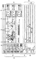
図1は、本発明の一実装に従うユーザインターフェースのスクリーンショットを示す。本発明には、ある特定の映像セグメントについて最初にトーンマッピングプロジェクトが起動される時に示されるスクリーンを作成するべく適合したアルゴリズムが含まれる。ここで、ある特定の映像セグメントは、1つのフレーム、1つのシーケンス、または動画全体とすることができる。 FIG. 1 shows a screenshot of a user interface according to one implementation of the present invention. The present invention includes an algorithm adapted to create a screen that is shown when a tone mapping project is first launched for a particular video segment. Here, a specific video segment may be one frame, one sequence, or the entire moving image.
図1には、HDR変換を実行する領域ベース方式の現在映像出力セクション12、および、例えば大域的処理を使用してHDR変換を実行する参照方式の現在映像出力セクション14を含む映像再生領域10が含まれる。各セクション12、14は、関連映像セクション15およびヒストグラム領域18を有する。ヒストグラム領域18は、映像セクション15に表示されている現在のフレームのヒストグラムを示す。図1の実装において、ヒストグラム領域18全体が、元のHDR画像のヒストグラムをlog2のスケールで示す。ヒストグラムは、明度の関数としてのポピュレーションデータである。
FIG. 1 shows a
各ヒストグラム領域にはまた、どのようにヒストグラムが領域ベースの処理用の領域に分割されたのかを示す1つまたは複数のアンカーポイント16も含まれる。セクション14の参照方式がHDRコンテンツを処理する大域的な方法であるという仮定であるため、1つの領域のみ、および1つのアンカーポイントのみが存在していることに留意されたい。領域ベース方法は、対応するアンカーポイントに関連するヒストグラム値に対して動作する。アンカーポイント(例えば、左から3番目のアンカーポイントなど)に関連するヒストグラム値を、例えば、2番目と3番目のアンカーポイント間の中間点から3番目と4番目のアンカーポイント間の中間点へ広がる値として定義することができる。領域ベース方法および参照方法用の現在の映像フレームが表示されると、例えば、映像技術者が、リアルタイムで2つの処理方式間の出力における違いを確認することが可能となる。セクションすなわち映像再生領域10にはまた、映像セグメント内での現在の位置を示す運転タイマ、および映像セグメントの再生を制御するための一連の制御ボタンを提供するタイマセクション19も含まれる。
Each histogram region also includes one or
アンカーポイントは、所与のオペレータに対応するフレームのセットに対して計算されることに留意されたい。これについては、下記でパラメータ設定領域およびダークルームの検討においてさらに説明する。 Note that the anchor point is calculated for a set of frames corresponding to a given operator. This will be further described below in the discussion of the parameter setting area and dark room.
図1には、現在のフレームの赤のヒストグラム22、緑のヒストグラム24、および青のヒストグラム26を含むヒストグラム領域20を含む。各カラーヒストグラム22、24、26はまた、「露出過度」および「露出不足」の画素それぞれのレベルを示す関連する読出部28を有する。読出部28は、最大値(8ビットフィールドについては、最大は通常255)である画素の数を「露出過度」の読出情報により示す。読出部28はまた、8ビットフィールドについて最低値とすることができる画素の数を「露出不足」の読出情報により示し、それにおいて最低は通常0である。読出部28の他の実装では、例えば、露出過度または露出不足の画素の、実際の数ではなくパーセンテージでの表示を使用することができる。カラーヒストグラム22、24、26は、例えば、現在の領域ベースの設定によって1つまたは複数の色の飽和が生成されているかどうかを示すことにより、有用とすることができる。
FIG. 1 includes a
図1には、例えば、露出およびコントラストを制御するためのパラメータ設定領域30が含まれる。露出およびコントラストが含まれているのは、これらが通常は見る者のほとんどのおよび/または映像技術者のほとんどが理解する高レベルなパラメータであると考えられるためである。領域30は、領域ベース制御セクション32および全領域制御セクション34を含む。領域ベース制御セクション32は、各領域の露出およびコントラスト用の別々の制御を含む。図1には、セクション32に5つの領域が示され、該5つの領域は5つのアンカーポイント16に対応する。各領域の露出および/またはコントラストを別々に変更することができ、または、露出および/またはコントラストを、全領域(大域的)制御セクション34を使用して変更することもできる。全領域制御セクション34用の制御を移動させることにより、全ての領域が同時に変更されるように、アルゴリズムが適合している。制御は、例えば、マウスまたは他のポインティングデバイスを使用することにより移動可能なスライドバーとして示すことができる。
FIG. 1 includes, for example, a
領域ベース制御セクション32にはまた、領域ごとに、マスク、重み画像、またはグレースケール画像36が含まれ、フレームの様々な領域の画像が図の36の点線内に示され、表現を簡単にするために「区分」という表記で表されており、これらの画像は映像再生領域10内の画像のスケーリングされた画像である。マスクは、現在のフレームのどの部分が当該領域の中にあるのかを示す。マスクはこの情報を、より高い輝度すなわちより明るい値を、当該領域内に存在するという高い可能性または重みを有する場所に対して使用することにより、提供する。映像セグメントが再生されると、ユーザは、重み画像がフレームごとに変化するのを確認することができ、また、それにより、幾つの数のフレームが異なる領域を使用またはポピュレートするのかを視覚的表示により確認することができる
制御セクション32、34は、現在のオペレータにより操作されているフレームのセット全体に適用される。これについてはダークルームについての項でさらに説明する。
The region-based
図1には、ユーザが、ジョブ設定、トーンマッピング、および微調整などの種々の情報についての情報を見ることができるワークフロー領域40が含まれる。微調整のオプションが図1に表示されており、ダークルームについての検討において説明されるように、映像技術者が選択可能かつ映像セグメントに対して適用可能な種々のオペレータおよびフィルタが含まれる。図1に示される微調整のオプションには、トーンマッピングオペレータ、明順応オペレータ、および後処理フィルタが含まれる。
FIG. 1 includes a
トーンマッピングオペレータには、例えば、大域的アルゴリズムを適用する既知のトーンマッピング技術を指す単一露出オペレータ、および領域ベースオペレータを含むことができる。領域ベースオペレータは、独自のトーンマッピングアルゴリズムを指す。他のトーンマッピングオペレータを選択し映像セグメントの処理に使用しても良い。 Tone mapping operators can include, for example, single exposure operators that point to known tone mapping techniques that apply global algorithms, and region-based operators. A region-based operator refers to a unique tone mapping algorithm. Other tone mapping operators may be selected and used to process the video segment.
明順応オペレータには、例えば、遷移処理部が含まれる。光が動的に変化している映像セグメントの一部において、単一オペレータを使用するより遷移処理部を使用する方が好ましいことがある。本実装の遷移処理部は、以下のダークルームについての検討で説明するように両側にあるオペレータの間を補間して露出およびコントラストの設定を自動的に選択する。さらに、選択された露出およびコントラストの設定をフレームごとに変更することができ、これは、光がフレームごとに変化している場合には重要であろう。加えて、遷移処理部において、アンカーポイントおよび関連する区分はフレームごとに変更される可能性もあり、1つのシーンを通して不変のままではない。 The light adaptation operator includes, for example, a transition processing unit. It may be preferable to use a transition processor over a single operator in a portion of the video segment where the light is changing dynamically. The transition processing unit of this implementation automatically selects the exposure and contrast settings by interpolating between the operators on both sides, as will be described in the following discussion of dark room. In addition, the selected exposure and contrast settings can be changed from frame to frame, which may be important if the light is changing from frame to frame. In addition, in the transition processor, anchor points and associated segments may change from frame to frame and remain unchanged throughout a scene.
後処理フィルタには、例えば、ぼかしフィルタおよび鮮鋭化フィルタが含まれる。周知のように、他のフィルタも含むことができ、映像セグメントの処理に使用することもできる。フィルタを、トーンマッピングされた出力に適用するが、トーンマッピングの前に適用することもできる。 The post-processing filter includes, for example, a blur filter and a sharpening filter. As is well known, other filters can also be included and used to process video segments. The filter is applied to the tone mapped output, but can be applied before tone mapping.
ワークフロー領域40により、ユーザは、例えば、HDRファイルをどこから開くか、トーンマッピングされた出力をどこに保存するかなどのジョブ設定についての情報を制御することもできる。また、ワークフロー領域40により、ユーザは自動トーンマッピングまたは対話型の領域ベーストーンマッピングを選択することもできる。
The
図1には、ダークルーム領域50が含まれる。ダークルーム領域50は、映像セグメントの各フレームの平均輝度を示す平均輝度曲線52、セクション12および14に現在表示されているフレームの時間を示す、図1では現在時間が66秒の位置に点で示されているタイムチャート54、映像セグメントに適用されている種々のフィルタおよびオペレータが貼り付けられている特定の時間スパンを示すオペレータセクション55を含むことができる。セクション55は、図1では例として、領域ベースオペレータ56、続いて遷移処理部57、続いて別の領域ベースオペレータ58を含む。図面全てにおいてオペレータセクション55には、特定のオペレータセクション内のフレームの小さな画像が示され、画像は表現を簡単にするために「区分」として示されている。
FIG. 1 includes a
映像技術者または他のユーザは、例えば、領域ベースオペレータをワークフロー領域40の微調整セクションからドラッグして、オペレータセクション55にドロップすることができる。そして、映像技術者は、挿入されたオペレータの両端を調整してオペレータを所望の時間スパンに貼り付けることが可能である。映像技術者は、典型的に別々の領域ベースオペレータを異なるシーケンスに貼り付けること、そして、遷移オペレータ57を2つのシーケンスの間の遷移期間に貼り付けることが可能である。遷移オペレータ57を、例えば、当該2つの領域ベースオペレータの間を補間するべく設計することができる。一実装において、遷移処理部は、遷移処理部が定義される時間の全スパンに対して補間を実行する。従って、例えば、図1において、領域ベースオペレータ56の終了時間より前に事実上遷移処理部57は始まり、また、領域ベースオペレータ58の開始時間の後に事実上遷移処理部57は終わる。しかし、遷移処理部57が開始される時に実効的には領域ベースオペレータが停止され、遷移処理部57が終了するまで領域ベースオペレータ58は開始されない。
A video engineer or other user can, for example, drag an area-based operator from the fine tuning section of the
本実装においては全てのオペレータが自動的に作成されるが、オペレータを手動で追加および調整しても良い。各オペレータは、オペレータの境界と一致するタイムチャート54上の位置で示されるように、フレームのある特定の範囲に対して作用する。各オペレータのパラメータが推定され、コントラストおよび露出のパラメータとしてパラメータ設定領域30に示される。
In this implementation, all operators are created automatically, but operators may be added and adjusted manually. Each operator acts on a particular range of frames, as indicated by a position on the
加えて、先に示したように、アンカーポイントが各オペレータに対して決められ、露出およびコントラストの制御が各オペレータに対して適用される。これは、オペレータが時間に合わせて調整されて所与のオペレータが特定の映像シーケンスに貼り付けられるだけの典型的な用途においては有用である。このように、アンカーポイントが変わらないため、それぞれの特定の映像シーケンスには、一定の露出設定、一定のコントラスト設定を行うことができ、また、領域の境界を、シーンを通して比較的一定にすることができる。 In addition, as indicated above, anchor points are determined for each operator and exposure and contrast controls are applied for each operator. This is useful in typical applications where an operator is adjusted in time and a given operator is pasted into a particular video sequence. In this way, since the anchor point does not change, each specific video sequence can have a constant exposure setting and a constant contrast setting, and the boundary of the region should be relatively constant throughout the scene. Can do.
図2は、ユーザがオペレータ58の作用範囲を変更した結果を示す。ユーザは、オペレータ58の開始時間を右方向、タイムチャート54上でもっと遅い時間にドラッグすると、開始時間が3:62辺りに示される。より一般的には、ユーザはいずれのオペレータの作用範囲も変更することが可能である。現在のフレームが3:62であることが示され、セクション22において赤のヒストグラムの飽和が示されている。
FIG. 2 shows the result of the user changing the operating range of the
図4は、ユーザが新しいオペレータを追加した結果を示す。ここでは、単一露出オペレータ59である。通常のHDRアプリケーションでは、多くの異なるトーンマッピング方法が利用可能である。ユーザは、各シーンについて異なるトーンマッピング方法を選択可能である。図4は、ワークフロー領域40からダークルーム50に単一露出オペレータが挿入されたことを示している。
FIG. 4 shows the result of the user adding a new operator. Here, it is a single exposure operator 59. In normal HDR applications, many different tone mapping methods are available. The user can select different tone mapping methods for each scene. FIG. 4 shows that a single exposure operator has been inserted from the
図5は、ユーザがさらにオペレータを追加した結果を示す。ユーザは、これらのオペレータを追加して、例えば、異なる機能性を実現することができる。例えば、遷移処理部は、本実装において、遷移処理部の両側にあるオペレータ間のトーンマッピングのパラメータを補間する。加えて、ぼかしフィルタ60は、ワークフロー領域40からダークルーム50にドラッグされたもので、遷移オペレータの下に挿入されて示されている。ぼかしフィルタにより、後処理フィルタとしてトーンマッピングされたフレームにガウシアンぼかしが適用される。
FIG. 5 shows the result of the user adding more operators. The user can add these operators to achieve different functionality, for example. For example, the transition processing unit in this implementation interpolates tone mapping parameters between operators on both sides of the transition processing unit. In addition, the
図示されるように、複数のオペレータを任意の所与のフレームに対して適用可能である。図5では、例えば、タイムチャート54上の時間およそ3:30辺りにおいて、領域ベースオペレータ58、遷移処理部61、ぼかしフィルタ60が全てアクティブであることが示されている。加えて、これら3つのオペレータは全て、異なる時間範囲で適用されている。しかし、露出/コントラストの設定およびアンカーポイントは、本実装において、遷移処理部の開始時間および終了時間に基づき決定されることに留意されたい。遷移処理部は、領域ベースオペレータと先行の単一露出オペレータとの間のスムーズな遷移を提供することを意図して適用される。本実装において、遷移処理部は、先行の単一露出オペレータの設定と続く領域ベースオペレータの設定との間を補間する。そして、遷移処理部によりトーンマッピングが実行された後に、トーンマッピングされた出力に対してぼかしフィルタ60が適用される。
As shown, multiple operators can be applied to any given frame. In FIG. 5, for example, it is shown that the
図6は、ユーザが露出およびコントラストのレベルを変更した結果を示す。それぞれのオペレータについて、ユーザは露出およびコントラストを領域ごとに変更することができる。露出は、所与の領域について該所与の領域の上部のスライダを移動させることにより変更される。コントラストは、全領域制御セクション34において所与の領域について該所与の領域の下部のスライダを移動させることにより変更される。図1と比較すると、領域10の露出およびコントラストのみが変更されている。なお、露出およびコントラストのレベルは、本実装ではオペレータごとに別々に設定される。これは、露出およびコントラストのレベルが、オペレータで操作されるフレームセット全体で同一であることを意味する。もちろん、領域は画素明度値に応じてフレームごとに変化することが予期されるが、露出およびコントラストの設定は同一のままである。
FIG. 6 shows the result of the user changing the level of exposure and contrast. For each operator, the user can change the exposure and contrast from region to region. The exposure is changed by moving the slider above the given area for the given area. The contrast is changed by moving the slider below the given area for the given area in the total
図7は、図1と比較すると、動いているHDRヒストグラム上のアンカーポイント16の結果を示す。異なるオペレータに対して、アンカーポイントを異なるようにすることが可能である。図7は、第3番目のシーンにおけるフレームを示す。比較すると、図1は第1番目のシーンにおけるフレームを示す。このように、異なるシーンではアンカーポイントを異なるようにすることが可能であるようにアルゴリズムが適合している。
FIG. 7 shows the result of
図8は、スクリーンに表示される出力により、映像セグメントの処理を行うユーザをどのように誘導することが可能かを示す。例えば、トーンマッピングされた画像のカラーヒストグラム22、24、26により、ユーザを誘導してパラメータを変更することができる。図8において、トーンマッピングされた画像の色ヒストグラムは、赤および青の両チャンネルにおける多数の飽和画素を示す。特に、赤および青のチャンネルの読出部28は、赤チャンネルでは18,386の露出過度の画素、青チャンネルでは11,635の露出過度の画素を示している。この情報により、ユーザを誘導して露出を減らすことができる。
FIG. 8 shows how the output displayed on the screen can guide the user to process the video segment. For example, the
アルゴリズムは、映像セグメントの処理を行うユーザを誘導することができる情報をスクリーンに提供するべく適合している。例えば、輝度曲線52は、各フレームの平均輝度を示し、シーンの境界がどこで発生するかについての有用なヒントを提供する。これにより、ダークルーム50においてオペレータの境界の選択を行うユーザを誘導することができる。
The algorithm is adapted to provide the screen with information that can guide the user to process the video segment. For example, the
キーフレームのアンカーポイントを対話形式で変更することも可能である。アンカーポイントは、HDRヒストグラム領域18に点16で例示されているが、HDR画像の領域への区分を定義する。例えば図1において、5つのアンカーポイントが定義され、対応する区分領域が5つのグレースケール画像または重み画像36として示されている。これらのグレースケール画像36において、上記で説明したように、輝点は、高い重みを有する現在の領域に画素が属することを意味し、その逆も同様である。ユーザが1つのアンカーポイントを変更すると、HDR画像の区分も変化し、その結果、図1の5つのグレースケール画像36が再計算され更新される。それと同時に、トーンマッピングされた画像15およびそのR、G、Bのカラーヒストグラム22、24、26も更新される。従って、このような場合、エンドユーザは、その区分全体に何らかの制御を行うこと、出力されたトーンマッピングされた画像15全体に何らかの制御を行うことができる。
It is also possible to change the anchor point of the key frame interactively. The anchor point is exemplified by the
スクリーン上には、アンカーポイントの修正を行うユーザを誘導するためのいくつかのヒントがある。HDRヒストグラム18は、アンカーポイントを置くべき最良の位置がどこであるかをユーザが判定するのに役立つ。例えば、一般的に、ダイナミックレンジ全体をカバーするにはアンカーポイント間に何らかの間隔を保つのが良い。これは、例えば、アンカーポイントをヒストグラムの中央部分に近接して置くこととは対照的である。「重み画像」はまた、ユーザがアンカーポイントを変更するための直感的なヒントも提供する。ユーザは、アンカーポイントを変更している間に重み画像を観察し、区分された領域が満足できるものであるかどうかを確認することができる。すなわち、ユーザは、領域がポピュレートされていること示す輝点が各重み画像内に存在するかどうかを観察することができる。領域がポピュレートされている場合、ユーザは、アンカーポイントを今ある位置に置いたままにすることができる。しかし、領域がポピュレートされていない場合、ユーザは、例えば、アンカーポイントを移動し、この領域がポピュレートかつ使用されるようにするためにポピュレートされていない領域を大きくすることができる。あるいは、または加えて、ユーザは、そのポピュレートされていない領域に関連するアンカーポイントを削除し、領域を拡大させてさらにポピュレートかつ使用されるようにすることを決定することもできる。
There are several hints on the screen to guide the user to modify the anchor point. The
アンカーポイントの数が通常は、対象のHDR画像/映像のダイナミックレンジに従って自動的に計算されるように、アルゴリズムを適合する。しかし、アンカーポイントを追加または削除することも可能である。利点は典型的にはアンカーポイントの変更と同様である。例えば、ユーザは、トーンマッピングされた画像全体にさらに微細な制御を行うために、さらに多くのアンカーポイントを追加可能である場合もある。 The algorithm is usually adapted so that the number of anchor points is automatically calculated according to the dynamic range of the subject HDR image / video. However, anchor points can be added or deleted. The advantage is typically similar to changing the anchor point. For example, the user may be able to add more anchor points for finer control over the entire tone mapped image.
図1の実装において、アンカーポイントは静的光を有するシーンでは通常固定される。従って、キーフレームのアンカーポイントの変更は同じシーンの全てのフレームに影響を与える。不透明な窓が次第に開き太陽の光が部屋に入る場合のような動的光を有するシーンでは、前のシーンおよび後に続くシーンの両方のアンカーポイントに従って、アンカーポイントが自動的に補間される。この場合、アンカーポイントは、動的光のシーン内の全てのフレームごとに変化する。通常、ユーザがこのような状況でアンカーポイントを変更する必要はない。 In the implementation of FIG. 1, anchor points are usually fixed in scenes with static light. Therefore, changing the anchor point of a key frame affects all frames in the same scene. In scenes with dynamic light, such as when opaque windows gradually open and sunlight enters the room, anchor points are automatically interpolated according to the anchor points of both the previous and subsequent scenes. In this case, the anchor point changes for every frame in the dynamic light scene. Normally, the user does not need to change the anchor point in such a situation.
パラメータ設定ウィンドウ30には、上部バーおよび下部バーで領域ごとに露出およびコントラストのパラメータが変更され、重み画像によって定義される。エンドユーザの観点からは、上部バーは輝度を変更し、下部バーはコントラストを変更する。ウィンドウの底部には、2つの付加的な大域パラメータ(すなわち、全領域制御セクション34)が設けられ、操作を簡素化させることもできる。大域的な露出用バーを動かすことにより、全領域についての露出のパラメータを変更し、大域的なコントラスト用バーを動かすことにより、全領域についてのコントラストのパラメータを変更する。これら2つの大域的なバーは状況に応じて、例えば、エンドユーザが大域的な輝度またはコントラストを変更したい場合に、使用することができる。例えば、トーンマッピングされた画像が明るすぎることにユーザが気付いた場合、ユーザは、露出のパラメータを領域ごとに別々に減少させる必要が無い。代わりに、ユーザは大域的な露出用バーを左方向に動かし、それによって,各領域用の全ての上部(露出用)バーを左方向に一斉に動かすことができる。
In the
図1に示される形式からは、多くの特徴を変形することができる。例えば、ヒストグラムを、1フレームだけではなく複数のフレームに関連させて良い。加えて、露出およびコントラストのパラメータを、1つのオペレータが適用される全てのフレームについて同一に設定する必要はなく、例えば、個々のフレームごとまたは小グループのフレームごとに設定しても良い。さらに、アンカーポイントを、1つのオペレータが適用される全てのフレームについて同一に設定する必要はなく、例えば、個々のフレームごとまたは小グループのフレームごとに設定しても良い。 Many features can be modified from the format shown in FIG. For example, a histogram may be associated with multiple frames instead of just one frame. In addition, the exposure and contrast parameters do not have to be set the same for all frames to which one operator is applied, but may be set, for example, for each individual frame or for a small group of frames. Furthermore, it is not necessary to set the anchor point the same for all frames to which one operator is applied. For example, the anchor point may be set for each individual frame or for each small group of frames.
要約すると、いくつかの実装を、映像セグメントに関する情報を表示すること、および、映像セグメントを処理するための機能(例えば、オペレータ)を表示することに関連して提供する。該機能によりユーザは、映像セグメントを処理すること、そして特に、HDR画像のトーンマッピングを実行することが可能となる。表示される結果および情報はヒストグラムおよび/または平均輝度とすることができ、該結果および情報により、どの機能を適用するかについて、または、それらの機能のための、開始時間、終了時間、露出および/またはコントラストなどのパラメータをどのように構成するかついて判定を行うユーザを誘導することもできる。これらの実装の変形形態および追加の用途が熟考され、かつ本開示内に含まれ、また、説明した実装の特徴および態様を他の実装に適合させても良い。 In summary, some implementations are provided in connection with displaying information about video segments and displaying functions (eg, operators) for processing video segments. This feature allows the user to process video segments and in particular to perform tone mapping of HDR images. The displayed results and information can be histograms and / or average brightness, which results and information about which function to apply, or for those functions, start time, end time, exposure and It is also possible to guide the user to make a determination in any way how to configure parameters such as contrast. Variations and additional uses of these implementations are contemplated and included within this disclosure, and the described implementation features and aspects may be adapted to other implementations.
本出願において説明した実装および特徴の内のいくつかを、H.264/MPEG−4AVC(AVC)規格、および/またはMVC拡張を用いたAVC、および/またはSVC拡張を用いたAVCの文脈で使用することができる。加えて、これらの実装および特徴を、別の規格の文脈で使用しても良く、または、規格を伴わない文脈においても使用して良い。 Some of the implementations and features described in this application are described in H.264. It can be used in the context of H.264 / MPEG-4 AVC (AVC) standard and / or AVC with MVC extension and / or AVC with SVC extension. In addition, these implementations and features may be used in the context of another standard or in a context that does not involve a standard.
多数の実装について説明てきたが、種々の修正を行って良いことが理解されるであろう。例えば、様々な実装の要素の組み合わせ、補足、修正、削除を行って他の実装を形成しても良い。加えて、当業者は理解するであろうが、他の構造および処理を開示したそれと置き換えて良く、その結果得られる実装により、少なくとも実質的に同じ機能(単数または複数)を、少なくとも実質的に同じ方法(単数または複数)で実行し、開示した実装と少なくとも実質的に同じ結果(単数または複数)を達成することになろう。従って、これらおよび他の実装が本出願により熟考される。 Although numerous implementations have been described, it will be understood that various modifications may be made. For example, other implementations may be formed by combining, supplementing, correcting, or deleting various implementation elements. In addition, those skilled in the art will appreciate that other structures and processes may be substituted for those disclosed, resulting in at least substantially the same function (s) being at least substantially It will perform in the same way (s) and achieve at least substantially the same result (s) as the disclosed implementation. Accordingly, these and other implementations are contemplated by this application.
以下のリストは多数の種々の実装をまとめたものである。このリストは、網羅することではなく、数多くの可能性のある実装のいくつかを単に例示することを意図するものである。
1.映像にトーンマッピングを実行するための情報の表示。
2.実装1、トーンマッピングを制御するユーザ入力を受け取ることを含む。
3.実装1−2、ユーザ入力の結果、表示される情報を変更する。
4.実装1−3、表示される情報は、トーンマッピング前の映像、トーンマッピング後の映像、参照モデルを使用したトーンマッピング後の映像、映像の処理に使用されるパラメータの内の1つまたは複数を含む。
5.実装4、パラメータは、1フレームまたは複数フレーム(例えばシーケンス)の平均輝度、1フレームまたは複数フレームの色ヒストグラム、1つまたは複数のフレームを領域に区分するためのアンカーポイントの位置、1つまたは複数の領域の露出またはコントラストの制御、オペレータの配置を示すタイムチャートの内の1つまたは複数を含む。
6.実装1−5、表示によりユーザにフレームベースのデータ(例えば、平均輝度)が示され、ユーザがオペレータの開始および/または終了の時間を入力し、ユーザが入力した新しい時間に基づく新しいトーンマッピングされた出力が、表示により示される。
7.実装1−5、表示により、ユーザに1つまたは複数の画像を区分するためのアンカーポイントが示され、ユーザがアンカーポイントを移動させ、その結果新しい区分が得られ、表示により、新しい区分(例えば、マスク)を示す情報が、新しい区分に基づく新しいトーンマッピングされた出力に加えて示される。
8.1つまたは複数の上記の実装を実行する、例えば、プリプロセッサ、エンコーダ、送信機、受信機、デコーダ、またはポストプロセッサに含まれる処理装置。
9.実装8の処理装置を含む、例えば、プリプロセッサ、エンコーダ、送信機、受信機、デコーダ、ポストプロセッサ、セットトップボックス、携帯電話、ラップトップもしくは他のパーソナルコンピュータ、PDA、または他の民生用通信機器などの装置。
10.1つまたは複数の上記の実装から生成される、または、1つまたは複数の上記の実装の装置により提供されるデータまたは記述的情報を含む信号。
本発明の好ましい実施形態を以下に示す。
付記1.映像再生領域と、
前記映像再生領域における、領域ベースのトーンマッピングのための領域的現在映像出力セクションと、
前記映像再生領域における、大域ベースのトーンマッピングのための大域的現在映像出力セクションと、
前記領域的現在映像出力セクションにおける領域的映像セクションおよび領域的ヒストグラム領域と、
前記大域的現在映像出力セクションにおける大域的映像セクションおよび大域的ヒストグラム領域と、
複数の領域に関する領域的可変露出制御および領域的可変コントラスト制御を有する領域的制御セクションと、
大域的可変露出制御および大域的可変コントラスト制御を有する大域的制御セクションと、
を備え、
前記領域的現在映像出力セクション、前記大域的現在映像出力セクション、前記映像セクション、前記ヒストグラム領域、および前記制御セクションはスクリーン上に同時に表示される、ユーザインターフェース。
付記2.前記大域的ヒストグラム領域においてアンカーポイントを備える、付記1に記載のユーザインターフェース。
付記3.前記アンカーポイントは、前記ユーザインターフェースを介して変更可能である、付記2に記載のユーザインターフェース。
付記4.オペレータセクションおよびタイムラインを備え、前記タイムラインは、処理されている映像のフレームの時間を示し、前記タイムラインおよび前記オペレータセクションは前記スクリーン上に同時に表示される、付記1に記載のユーザインターフェース。
付記5.前記処理されている映像のフレームの個々の色ヒストグラムを前記スクリーン上に同時に示す色ヒストグラム領域を備える、付記1に記載のユーザインターフェース。
付記6.前記色ヒストグラムに関連する個々の色について露出過度または露出不足である色ごとの画素の数の測定値を同時に示す読出セクションを前記色ヒストグラム領域において備える、付記5に記載のユーザインターフェース。
付記7.前記処理されている映像のフレームの個々の色ヒストグラムを前記スクリーン上に同時に示す色ヒストグラム領域を備える、付記4に記載のユーザインターフェース。
付記8.前記色ヒストグラムに関連する個々の色について露出過度または露出不足である色ごとの画素の数の測定値を同時に示す読出セクションを前記色ヒストグラム領域において備える、付記7に記載のユーザインターフェース。
付記9.前記オペレータセクションは前記タイムラインに沿って伸びる複数のオペレータバーを備え、前記オペレータバーは1つまたは複数のオペレータを保持かつ表示するように適合される、付記4に記載のユーザインターフェース。
付記10.前記オペレータは、ぼかしフィルタ、遷移処理部、領域ベースオペレータ、または大域ベースのオペレータである、付記9に記載のユーザインターフェース。
付記11.前記ユーザインターフェースは、ハイダイナミックレンジの映像データをロウダイナミックレンジの映像データに変換するように適合される、付記1に記載のユーザインターフェース。
付記12.映像データを処理する方法であって、
前記映像データのフレームをグラフィカルユーザインターフェースの映像再生領域に表示するステップであって、前記フレームが領域ベースのトーンマッピングのための領域的現在映像出力セクション、および大域ベースのトーンマッピングのための大域的現在映像出力セクションに表示され、前記領域的現在映像出力セクションおよび前記大域的現在映像出力セクションが並んで配置される、ステップと、
領域的制御セクションを前記映像再生領域に隣接して表示するステップであって、前記領域的制御セクションが、複数の領域に関する領域的可変露出制御手段および領域的可変コントラスト制御手段を有する、ステップと、
大域的制御セクションを前記領域的制御セクションに隣接して表示するステップであって、前記大域的制御セクションが、大域的可変露出制御手段および大域的可変コントラスト制御手段を有する、ステップと、
を含み、
前記領域的現在映像出力セクションおよび前記大域的現在映像出力セクションはスクリーン上に同時に表示される、前記方法。
付記13.領域的映像セクションおよび領域的ヒストグラム領域を前記領域的現在映像出力セクションに表示するステップであって、アンカーポイントが大域的ヒストグラム領域に表示される、ステップと、
大域的映像セクションおよび大域的ヒストグラム領域を前記大域的現在映像出力セクションに表示するステップと、
を含む、付記12に記載の方法。
付記14.オペレータセクションおよびタイムラインをお互いに隣接させて前記映像再生領域の下方に表示するステップであって、前記タイムラインは処理されている映像のフレームの時間を示し、前記タイムラインおよび前記オペレータセクションが前記スクリーン上に同時に表示される、ステップを含む、付記13に記載の方法。
付記15.前記処理されている映像のフレームの個々の色ヒストグラムを前記スクリーン上に同時に示す色ヒストグラム領域を表示するステップであって、前記色ヒストグラム領域が前記映像再生領域に隣接する、ステップを含む、付記14に記載の方法。
付記16.少なくとも、複数の領域に関する前記領域的可変露出制御手段または前記領域的可変コントラスト制御手段を調整することにより、前記グラフィカルユーザインターフェースを介して映像に変更を加えるステップであって、映像に対する前記変更の視覚的結果が前記映像再生領域に表示される、ステップを含む、付記15に記載の方法。
付記17.少なくとも1つのオペレータを前記オペレータセクションに追加することにより前記グラフィカルユーザインターフェースを介して映像に変更を加えるステップであって、映像に対する前記変更の視覚的結果が前記映像再生領域に表示される、ステップを含む、付記15に記載の方法。
The following list summarizes a number of different implementations. This list is not meant to be exhaustive, but merely intended to illustrate some of the many possible implementations.
1. Display information to perform tone mapping on video.
2.
3. Implementation 1-2, changes the displayed information as a result of user input.
4). Implementation 1-3, information to be displayed includes one or more of a video before tone mapping, a video after tone mapping, a video after tone mapping using a reference model, and parameters used for video processing. Including.
5.
6). Implementation 1-5, display shows user frame-based data (eg, average brightness), user enters operator start and / or end time, new tone mapping based on new time entered by user The output is shown by the display.
7). Implementation 1-5, the display shows the anchor point for partitioning one or more images to the user, the user moves the anchor point, resulting in a new partition, and the display displays a new partition (e.g. , Mask) is shown in addition to the new tone mapped output based on the new partition.
8. A processing device, eg, included in a preprocessor, encoder, transmitter, receiver, decoder, or postprocessor, that performs one or more of the above implementations.
9.
10. A signal containing data or descriptive information generated from one or more of the above implementations or provided by a device of one or more of the above implementations.
Preferred embodiments of the present invention are shown below.
A regional current video output section for region-based tone mapping in the video playback region;
A global current video output section for global-based tone mapping in the video playback area;
A regional video section and a regional histogram region in the regional current video output section;
A global video section and a global histogram area in the global current video output section;
A regional control section having regional variable exposure control and regional variable contrast control for multiple regions;
A global control section having global variable exposure control and global variable contrast control;
With
A user interface wherein the regional current video output section, the global current video output section, the video section, the histogram region, and the control section are displayed simultaneously on a screen.
Appendix 3. The user interface according to
Appendix 7. 5. The user interface of
Appendix 9. The user interface of
Appendix 11. The user interface of
Displaying the frame of video data in a video playback area of a graphical user interface, wherein the frame is a regional current video output section for area-based tone mapping, and a global for global-based tone mapping. Displayed in a current video output section, wherein the regional current video output section and the global current video output section are arranged side by side;
Displaying a regional control section adjacent to the video playback region, the regional control section comprising regional variable exposure control means and regional variable contrast control means for a plurality of regions;
Displaying a global control section adjacent to the regional control section, the global control section comprising global variable exposure control means and global variable contrast control means;
Including
The method, wherein the regional current video output section and the global current video output section are simultaneously displayed on a screen.
Appendix 13. Displaying a regional video section and a regional histogram region in the regional current video output section, wherein anchor points are displayed in a global histogram region;
Displaying a global video section and a global histogram area in the global current video output section;
The method according to
Appendix 17. Adding a change to the video via the graphical user interface by adding at least one operator to the operator section, wherein a visual result of the change to the video is displayed in the video playback area; The method of
Claims (4)
前記映像データのフレームをグラフィカルユーザインターフェースの映像再生領域に表示するステップであって、前記フレームが領域ベースのトーンマッピングのための領域的現在の映像出力セクション、および大域ベースのトーンマッピングのための大域的現在の映像出力セクションに表示され、前記領域的現在の映像出力セクションおよび前記大域的現在の映像出力セクションが並んで配置され、前記領域的現在の映像出力セクションは複数の露出領域及び複数のアンカーポイントを有し、前記大域的現在の映像出力セクションは単一の露出領域および単一のアンカーポイントを有する、ステップと、
領域的制御セクションを前記映像再生領域に隣接して表示するステップであって、前記領域的制御セクションが、複数の領域に関する領域的可変露出制御手段および領域的可変コントラスト制御手段を有し、前記領域的制御セクションが複数の露出領域に分割され、各露出領域はアンカーポイントに対応する、ステップと、
大域的制御セクションを前記領域的制御セクションに隣接して表示するステップであって、前記大域的制御セクションが、大域的可変露出制御手段および大域的可変コントラスト制御手段を有する、ステップと、
を含み、
前記領域的現在の映像出力セクションおよび前記大域的現在の映像出力セクションはスクリーン上に同時に表示される、前記方法。 A method of processing video data,
Displaying the frame of video data in a video playback area of a graphical user interface, wherein the frame is a regional current video output section for area-based tone mapping, and a global for global-based tone mapping. The regional current video output section and the global current video output section are arranged side by side, and the regional current video output section includes a plurality of exposure regions and a plurality of anchors. A global current video output section having a single exposed area and a single anchor point; and
Displaying a regional control section adjacent to the video playback region, the regional control section comprising regional variable exposure control means and regional variable contrast control means for a plurality of regions, the region A dynamic control section is divided into a plurality of exposed areas, each exposed area corresponding to an anchor point; and
A step of displaying a global control section adjacent to said area control section, the global control section, that have a global variable exposure control means and the global variable contrast control unit, the steps,
Including
The method, wherein the regional current video output section and the global current video output section are simultaneously displayed on a screen.
大域的映像セクションおよび大域的ヒストグラム領域を前記大域的現在の映像出力セクションに表示するステップであって、前記単一のアンカーポイントが前記大域的ヒストグラム領域に表示される、ステップと、
を含む、請求項1に記載の方法。 A step of displaying the regional video section and the area histogram region to the video output section of the regional current, the plurality of anchor points are displayed on the territory frequency histogram region, a step,
A step of displaying the global video section and a large frequency histogram region to the video output section of the global current, wherein the single anchor point is displayed on the global histogram region, a step,
The method of claim 1 comprising:
Displaying a color histogram area simultaneously showing on the screen individual color histograms of the frame of video being processed, the color histogram area being adjacent to the video playback area. 3. The method according to 3.
Applications Claiming Priority (3)
| Application Number | Priority Date | Filing Date | Title |
|---|---|---|---|
| US35860510P | 2010-06-25 | 2010-06-25 | |
| US61/358,605 | 2010-06-25 | ||
| PCT/US2011/041564 WO2011163438A1 (en) | 2010-06-25 | 2011-06-23 | Graphical user interface for tone mapping high dynamic range video |
Publications (3)
| Publication Number | Publication Date |
|---|---|
| JP2013537659A JP2013537659A (en) | 2013-10-03 |
| JP2013537659A5 JP2013537659A5 (en) | 2017-02-02 |
| JP6282863B2 true JP6282863B2 (en) | 2018-02-21 |
Family
ID=44477689
Family Applications (1)
| Application Number | Title | Priority Date | Filing Date |
|---|---|---|---|
| JP2013516759A Active JP6282863B2 (en) | 2010-06-25 | 2011-06-23 | Graphical user interface for tone mapping high dynamic range video |
Country Status (6)
| Country | Link |
|---|---|
| US (1) | US10108314B2 (en) |
| EP (1) | EP2586010B1 (en) |
| JP (1) | JP6282863B2 (en) |
| KR (1) | KR101843902B1 (en) |
| CN (1) | CN102959583B (en) |
| WO (1) | WO2011163438A1 (en) |
Families Citing this family (20)
| Publication number | Priority date | Publication date | Assignee | Title |
|---|---|---|---|---|
| US9064313B2 (en) * | 2012-09-28 | 2015-06-23 | Intel Corporation | Adaptive tone map to a region of interest to yield a low dynamic range image |
| US9955084B1 (en) | 2013-05-23 | 2018-04-24 | Oliver Markus Haynold | HDR video camera |
| EP3025483B1 (en) | 2013-07-25 | 2022-09-21 | Convida Wireless, LLC | End-to-end m2m service layer sessions |
| US9460499B2 (en) * | 2014-05-30 | 2016-10-04 | Shenzhen Mindray Bio-Medical Electronics Co., Ltd. | Systems and methods for selective enhancement of a region of interest in an image |
| KR102244918B1 (en) | 2014-07-11 | 2021-04-27 | 삼성전자주식회사 | Display controller for enhancing visibility and reducing power consumption and display system having same |
| USD766976S1 (en) * | 2014-08-18 | 2016-09-20 | Rockwell Collins, Inc. | Display panel with icon |
| US10277771B1 (en) | 2014-08-21 | 2019-04-30 | Oliver Markus Haynold | Floating-point camera |
| US10225485B1 (en) | 2014-10-12 | 2019-03-05 | Oliver Markus Haynold | Method and apparatus for accelerated tonemapping |
| KR102309676B1 (en) | 2015-07-24 | 2021-10-07 | 삼성전자주식회사 | User adaptive image compensator |
| US10114769B2 (en) * | 2015-08-19 | 2018-10-30 | Logitech Europe S.A. | Synchronization of computer peripheral effects |
| JP6451669B2 (en) | 2016-03-04 | 2019-01-16 | ソニー株式会社 | Evaluation apparatus, evaluation method, and camera system |
| WO2017196670A1 (en) | 2016-05-13 | 2017-11-16 | Vid Scale, Inc. | Bit depth remapping based on viewing parameters |
| US11503314B2 (en) | 2016-07-08 | 2022-11-15 | Interdigital Madison Patent Holdings, Sas | Systems and methods for region-of-interest tone remapping |
| US10932276B2 (en) | 2016-11-03 | 2021-02-23 | Convida Wireless, Llc | Frame structure in NR |
| EP3583780B1 (en) | 2017-02-17 | 2023-04-05 | InterDigital Madison Patent Holdings, SAS | Systems and methods for selective object-of-interest zooming in streaming video |
| US10706512B2 (en) * | 2017-03-07 | 2020-07-07 | Adobe Inc. | Preserving color in image brightness adjustment for exposure fusion |
| US11272237B2 (en) | 2017-03-07 | 2022-03-08 | Interdigital Madison Patent Holdings, Sas | Tailored video streaming for multi-device presentations |
| KR102553764B1 (en) * | 2017-07-13 | 2023-07-10 | 삼성전자주식회사 | Electronics apparatus, Display apparatus and contorl method thereof |
| CN109104633B (en) * | 2018-08-30 | 2021-09-28 | Oppo广东移动通信有限公司 | Video screenshot method and device, storage medium and mobile terminal |
| KR20210066856A (en) | 2018-09-27 | 2021-06-07 | 콘비다 와이어리스, 엘엘씨 | Subband operations in unlicensed spectrums of new radio |
Family Cites Families (43)
| Publication number | Priority date | Publication date | Assignee | Title |
|---|---|---|---|---|
| US5682326A (en) * | 1992-08-03 | 1997-10-28 | Radius Inc. | Desktop digital video processing system |
| JP4055092B2 (en) | 1998-04-27 | 2008-03-05 | ソニー株式会社 | Imaging apparatus and imaging method |
| JP4103192B2 (en) * | 1998-09-17 | 2008-06-18 | ソニー株式会社 | Editing system and editing method |
| US7786999B1 (en) * | 2000-10-04 | 2010-08-31 | Apple Inc. | Edit display during rendering operations |
| EP1393296A4 (en) * | 2001-06-08 | 2008-09-03 | Univ Southern California | High dynamic range image editing |
| US20020198789A1 (en) | 2001-06-22 | 2002-12-26 | Sony Corp. And Sony Music Entertainment, Inc. | Apparatus and method for identifying and purchasing music |
| US6968337B2 (en) | 2001-07-10 | 2005-11-22 | Audible Magic Corporation | Method and apparatus for identifying an unknown work |
| EP1345172A1 (en) * | 2002-02-26 | 2003-09-17 | Sony International (Europe) GmbH | Contrast enhancement for digital images |
| US7073127B2 (en) * | 2002-07-01 | 2006-07-04 | Arcsoft, Inc. | Video editing GUI with layer view |
| US7525697B2 (en) * | 2002-07-15 | 2009-04-28 | Olympus Corporation | White balance processing apparatus and processing method thereof |
| US6879731B2 (en) | 2003-04-29 | 2005-04-12 | Microsoft Corporation | System and process for generating high dynamic range video |
| US7492375B2 (en) * | 2003-11-14 | 2009-02-17 | Microsoft Corporation | High dynamic range image viewing on low dynamic range displays |
| US7751805B2 (en) | 2004-02-20 | 2010-07-06 | Google Inc. | Mobile image-based information retrieval system |
| US7805678B1 (en) * | 2004-04-16 | 2010-09-28 | Apple Inc. | Editing within single timeline |
| US20050243176A1 (en) | 2004-04-30 | 2005-11-03 | James Wu | Method of HDR image processing and manipulation |
| US7551776B2 (en) | 2004-07-22 | 2009-06-23 | Seiko Epson Corporation | Histogram generation apparatus and method for operating the same |
| US8355030B2 (en) * | 2005-01-07 | 2013-01-15 | Corel Corporation | Display methods for high dynamic range images and user interfaces for the same |
| US20060153445A1 (en) * | 2005-01-07 | 2006-07-13 | Ulead Systems, Inc. | Display methods for high dynamic range images and user interfaces for the same |
| US7873322B2 (en) | 2005-06-14 | 2011-01-18 | Acterna Llc | Ingress susceptibility on return path |
| US7660464B1 (en) * | 2005-12-22 | 2010-02-09 | Adobe Systems Incorporated | User interface for high dynamic range merge image selection |
| US7715047B2 (en) * | 2006-02-17 | 2010-05-11 | Seiko Epson Corporation | Image editing device |
| US7822289B2 (en) | 2006-07-25 | 2010-10-26 | Microsoft Corporation | Locally adapted hierarchical basis preconditioning |
| US8111941B2 (en) * | 2006-11-22 | 2012-02-07 | Nik Software, Inc. | Method for dynamic range editing |
| US8213711B2 (en) * | 2007-04-03 | 2012-07-03 | Her Majesty The Queen In Right Of Canada As Represented By The Minister Of Industry, Through The Communications Research Centre Canada | Method and graphical user interface for modifying depth maps |
| US20080263433A1 (en) * | 2007-04-14 | 2008-10-23 | Aaron Eppolito | Multiple version merge for media production |
| US8444560B2 (en) * | 2007-05-14 | 2013-05-21 | Abbott Diabetes Care Inc. | Method and apparatus for providing data processing and control in a medical communication system |
| US20110129148A1 (en) | 2007-12-17 | 2011-06-02 | Pavel Kisilev | Image processing using target values |
| US8237730B1 (en) * | 2008-01-23 | 2012-08-07 | Pixar Animation Studios | Tone mapping for motion pictures |
| ES2527932T3 (en) * | 2008-04-16 | 2015-02-02 | Fraunhofer-Gesellschaft zur Förderung der angewandten Forschung e.V. | Bit Depth Scalability |
| FR2939265A1 (en) * | 2008-12-03 | 2010-06-04 | Thomson Licensing | METHOD FOR DETECTING FILM MODE OR CAMERA MODE |
| US20100153520A1 (en) * | 2008-12-16 | 2010-06-17 | Michael Daun | Methods, systems, and media for creating, producing, and distributing video templates and video clips |
| US8339475B2 (en) | 2008-12-19 | 2012-12-25 | Qualcomm Incorporated | High dynamic range image combining |
| US8237743B2 (en) * | 2009-02-17 | 2012-08-07 | Xerox Corporation | Modification of images from a user's album for spot-the-differences |
| US9195898B2 (en) | 2009-04-14 | 2015-11-24 | Qualcomm Incorporated | Systems and methods for image recognition using mobile devices |
| US8818172B2 (en) * | 2009-04-14 | 2014-08-26 | Avid Technology, Inc. | Multi-user remote video editing |
| US8881013B2 (en) * | 2009-04-30 | 2014-11-04 | Apple Inc. | Tool for tracking versions of media sections in a composite presentation |
| US8631326B2 (en) * | 2009-04-30 | 2014-01-14 | Apple Inc. | Segmented timeline for a media-editing application |
| US20100281371A1 (en) * | 2009-04-30 | 2010-11-04 | Peter Warner | Navigation Tool for Video Presentations |
| TWI378718B (en) * | 2009-06-05 | 2012-12-01 | Univ Nat Taiwan | Method for scaling video content according to bandwidth rate |
| US8433150B2 (en) * | 2009-09-28 | 2013-04-30 | Peking University | Sample based tone mapping method for high dynamic range images |
| US8831340B2 (en) * | 2010-01-27 | 2014-09-09 | Adobe Systems Incorporated | Methods and apparatus for tone mapping high dynamic range images |
| US8525899B2 (en) * | 2010-05-27 | 2013-09-03 | Canon Kabushiki Kaisha | Image-capturing device, user interface and method for selective color balance adjustment |
| US8819557B2 (en) * | 2010-07-15 | 2014-08-26 | Apple Inc. | Media-editing application with a free-form space for organizing or compositing media clips |
-
2011
- 2011-06-23 KR KR1020127033668A patent/KR101843902B1/en active IP Right Grant
- 2011-06-23 EP EP11729347.2A patent/EP2586010B1/en active Active
- 2011-06-23 CN CN201180031460.5A patent/CN102959583B/en active Active
- 2011-06-23 JP JP2013516759A patent/JP6282863B2/en active Active
- 2011-06-23 WO PCT/US2011/041564 patent/WO2011163438A1/en active Application Filing
- 2011-06-23 US US13/805,185 patent/US10108314B2/en active Active
Also Published As
| Publication number | Publication date |
|---|---|
| JP2013537659A (en) | 2013-10-03 |
| CN102959583B (en) | 2016-08-03 |
| US20130091430A1 (en) | 2013-04-11 |
| EP2586010A1 (en) | 2013-05-01 |
| US10108314B2 (en) | 2018-10-23 |
| KR20130085371A (en) | 2013-07-29 |
| WO2011163438A1 (en) | 2011-12-29 |
| EP2586010B1 (en) | 2018-08-08 |
| KR101843902B1 (en) | 2018-04-02 |
| CN102959583A (en) | 2013-03-06 |
Similar Documents
| Publication | Publication Date | Title |
|---|---|---|
| JP6282863B2 (en) | Graphical user interface for tone mapping high dynamic range video | |
| US9832378B2 (en) | Exposure mapping and dynamic thresholding for blending of multiple images using floating exposure | |
| US10672363B2 (en) | Color rendering for images in extended dynamic range mode | |
| EP3745390B1 (en) | Transitioning between video priority and graphics priority | |
| JP5615973B2 (en) | Device operation for capturing high dynamic range images | |
| JP5159208B2 (en) | Image correction method and apparatus | |
| JP4191241B2 (en) | Visual processing device, visual processing method, program, display device, and integrated circuit | |
| RU2544793C2 (en) | Image processing device and control method therefor | |
| CN102946513B (en) | A kind of method, device and terminal starting filming apparatus high dynamic range function | |
| US20150070537A1 (en) | Lens Shading Modulation | |
| JP5762756B2 (en) | Image processing apparatus, image processing method, image processing program, and photographing apparatus | |
| KR20180044919A (en) | Reverse tone mapping based on luminance zones | |
| US20070024721A1 (en) | Compensating for improperly exposed areas in digital images | |
| US20130308012A1 (en) | Image processing apparatus, image processing method, photographic imaging apparatus, and recording device recording image processing program | |
| JP2008515063A (en) | Method and apparatus for aesthetically enhanced image conversion | |
| JP2009520398A (en) | Apparatus and method for automatically adjusting display under varying lighting conditions | |
| JP2007241224A (en) | Moving image reproducing apparatus and gray scale correcting apparatus | |
| JP2007288587A (en) | Video adjusting device, video adjusting method and video processing program | |
| JP2023052085A (en) | Pixel contrast control system and method | |
| US8818094B2 (en) | Image processing apparatus, image processing method and recording device recording image processing program | |
| JP2012093904A (en) | Image processing device, image processing method, imaging device, and image processing program |
Legal Events
| Date | Code | Title | Description |
|---|---|---|---|
| A521 | Request for written amendment filed |
Free format text: JAPANESE INTERMEDIATE CODE: A523 Effective date: 20140623 |
|
| A621 | Written request for application examination |
Free format text: JAPANESE INTERMEDIATE CODE: A621 Effective date: 20140623 |
|
| A977 | Report on retrieval |
Free format text: JAPANESE INTERMEDIATE CODE: A971007 Effective date: 20150430 |
|
| A131 | Notification of reasons for refusal |
Free format text: JAPANESE INTERMEDIATE CODE: A131 Effective date: 20150707 |
|
| A601 | Written request for extension of time |
Free format text: JAPANESE INTERMEDIATE CODE: A601 Effective date: 20151007 |
|
| A521 | Request for written amendment filed |
Free format text: JAPANESE INTERMEDIATE CODE: A523 Effective date: 20160107 |
|
| A131 | Notification of reasons for refusal |
Free format text: JAPANESE INTERMEDIATE CODE: A131 Effective date: 20160614 |
|
| A601 | Written request for extension of time |
Free format text: JAPANESE INTERMEDIATE CODE: A601 Effective date: 20160914 |
|
| RD03 | Notification of appointment of power of attorney |
Free format text: JAPANESE INTERMEDIATE CODE: A7423 Effective date: 20161125 |
|
| RD04 | Notification of resignation of power of attorney |
Free format text: JAPANESE INTERMEDIATE CODE: A7424 Effective date: 20161128 |
|
| A524 | Written submission of copy of amendment under article 19 pct |
Free format text: JAPANESE INTERMEDIATE CODE: A524 Effective date: 20161214 |
|
| A02 | Decision of refusal |
Free format text: JAPANESE INTERMEDIATE CODE: A02 Effective date: 20170207 |
|
| A61 | First payment of annual fees (during grant procedure) |
Free format text: JAPANESE INTERMEDIATE CODE: A61 Effective date: 20180125 |
|
| R150 | Certificate of patent or registration of utility model |
Ref document number: 6282863 Country of ref document: JP Free format text: JAPANESE INTERMEDIATE CODE: R150 |
|
| S111 | Request for change of ownership or part of ownership |
Free format text: JAPANESE INTERMEDIATE CODE: R313113 |
|
| S531 | Written request for registration of change of domicile |
Free format text: JAPANESE INTERMEDIATE CODE: R313531 |
|
| R350 | Written notification of registration of transfer |
Free format text: JAPANESE INTERMEDIATE CODE: R350 |
|
| R250 | Receipt of annual fees |
Free format text: JAPANESE INTERMEDIATE CODE: R250 |
|
| R250 | Receipt of annual fees |
Free format text: JAPANESE INTERMEDIATE CODE: R250 |
|
| R250 | Receipt of annual fees |
Free format text: JAPANESE INTERMEDIATE CODE: R250 |
|
| R250 | Receipt of annual fees |
Free format text: JAPANESE INTERMEDIATE CODE: R250 |