JP6282543B2 - Evaporative fuel supply device - Google Patents
Evaporative fuel supply device Download PDFInfo
- Publication number
- JP6282543B2 JP6282543B2 JP2014142144A JP2014142144A JP6282543B2 JP 6282543 B2 JP6282543 B2 JP 6282543B2 JP 2014142144 A JP2014142144 A JP 2014142144A JP 2014142144 A JP2014142144 A JP 2014142144A JP 6282543 B2 JP6282543 B2 JP 6282543B2
- Authority
- JP
- Japan
- Prior art keywords
- purge
- pressure
- passage
- opening
- valve
- Prior art date
- Legal status (The legal status is an assumption and is not a legal conclusion. Google has not performed a legal analysis and makes no representation as to the accuracy of the status listed.)
- Active
Links
- 239000000446 fuel Substances 0.000 title claims description 244
- 238000010926 purge Methods 0.000 claims description 553
- 238000002485 combustion reaction Methods 0.000 claims description 76
- 238000001514 detection method Methods 0.000 claims description 63
- 238000002347 injection Methods 0.000 claims description 41
- 239000007924 injection Substances 0.000 claims description 41
- 239000012530 fluid Substances 0.000 claims description 29
- 238000005259 measurement Methods 0.000 claims description 12
- 230000001052 transient effect Effects 0.000 claims description 8
- 230000003111 delayed effect Effects 0.000 claims description 4
- 238000000034 method Methods 0.000 description 113
- 238000010586 diagram Methods 0.000 description 8
- 239000003054 catalyst Substances 0.000 description 7
- 102220573299 Coiled-coil domain-containing protein 92_S70C_mutation Human genes 0.000 description 6
- 239000002828 fuel tank Substances 0.000 description 5
- 239000007789 gas Substances 0.000 description 4
- 230000002265 prevention Effects 0.000 description 3
- 102220005308 rs33960931 Human genes 0.000 description 3
- 230000003584 silencer Effects 0.000 description 3
- XLYOFNOQVPJJNP-UHFFFAOYSA-N water Substances O XLYOFNOQVPJJNP-UHFFFAOYSA-N 0.000 description 3
- 230000004580 weight loss Effects 0.000 description 3
- 102220480688 Alkaline phosphatase, germ cell type_R60A_mutation Human genes 0.000 description 2
- 102220485769 Glycophorin-A_P90C_mutation Human genes 0.000 description 2
- 102220495689 Putative uncharacterized protein FLJ43944_R40A_mutation Human genes 0.000 description 2
- 102220352372 c.148T>G Human genes 0.000 description 2
- 239000003502 gasoline Substances 0.000 description 2
- 102200033501 rs387907005 Human genes 0.000 description 2
- 102200059794 rs587777021 Human genes 0.000 description 2
- 102200046443 rs9014 Human genes 0.000 description 2
- 238000007792 addition Methods 0.000 description 1
- QVGXLLKOCUKJST-UHFFFAOYSA-N atomic oxygen Chemical compound [O] QVGXLLKOCUKJST-UHFFFAOYSA-N 0.000 description 1
- 239000002826 coolant Substances 0.000 description 1
- 238000001816 cooling Methods 0.000 description 1
- 238000012217 deletion Methods 0.000 description 1
- 230000037430 deletion Effects 0.000 description 1
- 239000000428 dust Substances 0.000 description 1
- 238000004880 explosion Methods 0.000 description 1
- 239000007788 liquid Substances 0.000 description 1
- 239000000203 mixture Substances 0.000 description 1
- 239000001301 oxygen Substances 0.000 description 1
- 229910052760 oxygen Inorganic materials 0.000 description 1
- 238000005086 pumping Methods 0.000 description 1
- 238000000746 purification Methods 0.000 description 1
- 238000004904 shortening Methods 0.000 description 1
- 239000007921 spray Substances 0.000 description 1
- 239000000126 substance Substances 0.000 description 1
- 230000001629 suppression Effects 0.000 description 1
Images


Classifications
-
- F—MECHANICAL ENGINEERING; LIGHTING; HEATING; WEAPONS; BLASTING
- F02—COMBUSTION ENGINES; HOT-GAS OR COMBUSTION-PRODUCT ENGINE PLANTS
- F02D—CONTROLLING COMBUSTION ENGINES
- F02D41/00—Electrical control of supply of combustible mixture or its constituents
- F02D41/0025—Controlling engines characterised by use of non-liquid fuels, pluralities of fuels, or non-fuel substances added to the combustible mixtures
- F02D41/003—Adding fuel vapours, e.g. drawn from engine fuel reservoir
- F02D41/0032—Controlling the purging of the canister as a function of the engine operating conditions
- F02D41/004—Control of the valve or purge actuator, e.g. duty cycle, closed loop control of position
-
- F—MECHANICAL ENGINEERING; LIGHTING; HEATING; WEAPONS; BLASTING
- F02—COMBUSTION ENGINES; HOT-GAS OR COMBUSTION-PRODUCT ENGINE PLANTS
- F02D—CONTROLLING COMBUSTION ENGINES
- F02D41/00—Electrical control of supply of combustible mixture or its constituents
- F02D41/0025—Controlling engines characterised by use of non-liquid fuels, pluralities of fuels, or non-fuel substances added to the combustible mixtures
- F02D41/003—Adding fuel vapours, e.g. drawn from engine fuel reservoir
- F02D41/0042—Controlling the combustible mixture as a function of the canister purging, e.g. control of injected fuel to compensate for deviation of air fuel ratio when purging
-
- F—MECHANICAL ENGINEERING; LIGHTING; HEATING; WEAPONS; BLASTING
- F02—COMBUSTION ENGINES; HOT-GAS OR COMBUSTION-PRODUCT ENGINE PLANTS
- F02M—SUPPLYING COMBUSTION ENGINES IN GENERAL WITH COMBUSTIBLE MIXTURES OR CONSTITUENTS THEREOF
- F02M25/00—Engine-pertinent apparatus for adding non-fuel substances or small quantities of secondary fuel to combustion-air, main fuel or fuel-air mixture
- F02M25/08—Engine-pertinent apparatus for adding non-fuel substances or small quantities of secondary fuel to combustion-air, main fuel or fuel-air mixture adding fuel vapours drawn from engine fuel reservoir
- F02M25/0836—Arrangement of valves controlling the admission of fuel vapour to an engine, e.g. valve being disposed between fuel tank or absorption canister and intake manifold
-
- F—MECHANICAL ENGINEERING; LIGHTING; HEATING; WEAPONS; BLASTING
- F02—COMBUSTION ENGINES; HOT-GAS OR COMBUSTION-PRODUCT ENGINE PLANTS
- F02M—SUPPLYING COMBUSTION ENGINES IN GENERAL WITH COMBUSTIBLE MIXTURES OR CONSTITUENTS THEREOF
- F02M25/00—Engine-pertinent apparatus for adding non-fuel substances or small quantities of secondary fuel to combustion-air, main fuel or fuel-air mixture
- F02M25/08—Engine-pertinent apparatus for adding non-fuel substances or small quantities of secondary fuel to combustion-air, main fuel or fuel-air mixture adding fuel vapours drawn from engine fuel reservoir
- F02M25/089—Layout of the fuel vapour installation
-
- F—MECHANICAL ENGINEERING; LIGHTING; HEATING; WEAPONS; BLASTING
- F02—COMBUSTION ENGINES; HOT-GAS OR COMBUSTION-PRODUCT ENGINE PLANTS
- F02M—SUPPLYING COMBUSTION ENGINES IN GENERAL WITH COMBUSTIBLE MIXTURES OR CONSTITUENTS THEREOF
- F02M61/00—Fuel-injectors not provided for in groups F02M39/00 - F02M57/00 or F02M67/00
- F02M61/14—Arrangements of injectors with respect to engines; Mounting of injectors
- F02M61/145—Arrangements of injectors with respect to engines; Mounting of injectors the injection nozzle opening into the air intake conduit
-
- F—MECHANICAL ENGINEERING; LIGHTING; HEATING; WEAPONS; BLASTING
- F02—COMBUSTION ENGINES; HOT-GAS OR COMBUSTION-PRODUCT ENGINE PLANTS
- F02D—CONTROLLING COMBUSTION ENGINES
- F02D2200/00—Input parameters for engine control
- F02D2200/02—Input parameters for engine control the parameters being related to the engine
- F02D2200/04—Engine intake system parameters
- F02D2200/0406—Intake manifold pressure
Landscapes
- Engineering & Computer Science (AREA)
- Chemical & Material Sciences (AREA)
- Combustion & Propulsion (AREA)
- Mechanical Engineering (AREA)
- General Engineering & Computer Science (AREA)
- Supplying Secondary Fuel Or The Like To Fuel, Air Or Fuel-Air Mixtures (AREA)
- Electrical Control Of Air Or Fuel Supplied To Internal-Combustion Engine (AREA)
Description
本発明は、キャニスタに貯蔵した蒸発燃料を、吸気管を経由させて内燃機関に供給する蒸発燃料供給装置に関する。 The present invention relates to an evaporated fuel supply device that supplies evaporated fuel stored in a canister to an internal combustion engine via an intake pipe.
従来より、例えば内燃機関を搭載した車両では、燃料タンク内等で発生する蒸発燃料をキャニスタ内に一時的に貯蔵(吸着)している。そして、内燃機関の運転中(所定条件を満足する運転中)に、キャニスタに大気を導入しながら吸気管から吸引することで、キャニスタ内の蒸発燃料を、吸気管を経由させて内燃機関に吸引させて燃焼させるパージ制御を行っている。そして、このパージ制御を行うことで、キャニスタ内の蒸発燃料を大気に放出することなく燃焼させ、地球環境への影響を低減させている。 Conventionally, for example, a vehicle equipped with an internal combustion engine temporarily stores (adsorbs) evaporated fuel generated in a fuel tank or the like in a canister. During operation of the internal combustion engine (during operation satisfying predetermined conditions), the fuel vapor in the canister is sucked into the internal combustion engine via the intake pipe while being sucked from the intake pipe while introducing air into the canister. Purging control is performed to burn it. By performing this purge control, the evaporated fuel in the canister is burned without being released to the atmosphere, thereby reducing the influence on the global environment.
例えば内燃機関がガソリンエンジンの車両の場合、パージ制御を行った際には、インジェクタから噴射する燃料に加えてキャニスタからの蒸発燃料分が増加するので、三元触媒の浄化効率を維持するよう理論空燃比(λ=1.0)を保つためには、インジェクタからの燃料噴射量を蒸発燃料分だけ減量する必要がある。従って、パージ制御を開始してから、キャニスタからの蒸発燃料が、どれくらい遅れて内燃機関に到達するか(シリンダ内に吸引されるか)、というキャニスタから内燃機関(内燃機関のシリンダ内)までの蒸発燃料の到達遅れ時間が非常に重要となる。 For example, when the internal combustion engine is a gasoline engine vehicle, when purging control is performed, the amount of fuel evaporated from the canister in addition to the fuel injected from the injector increases, so the theory is to maintain the purification efficiency of the three-way catalyst. In order to maintain the air-fuel ratio (λ = 1.0), it is necessary to reduce the fuel injection amount from the injector by the amount of the evaporated fuel. Therefore, from the start of the purge control to the internal combustion engine (inside the cylinder of the internal combustion engine) from how long the evaporated fuel from the canister reaches the internal combustion engine (whether it is sucked into the cylinder). The arrival delay time of the evaporated fuel is very important.
また近年の内燃機関では、ターボチャージャやスーパーチャージャ等の過給機を備えたものが有る。過給機を備えた内燃機関では、過給状態に応じて、吸気管内の圧力が負圧になる場合と正圧(大気圧より高い圧力)になる場合がある。また過給機を備えていない場合でも、バックファイヤが発生した場合等では、吸気管内の圧力が正圧になる場合がある。吸気管内の圧力が負圧である場合は、キャニスタに大気を導入しながら、キャニスタ内の蒸発燃料を、吸気管を経由させて内燃機関に吸引させることができる。しかし、吸気管内の圧力が正圧である場合は、キャニスタ内の蒸発燃料を吸引できないどころか吸気管からキャニスタへと吸気が逆流してしまうので好ましくない。そこで、キャニスタと吸気管とを連通するパージ通路に、キャニスタから吸気管に向かう方向への流体の流れを許容し、吸気管からキャニスタに向かう方向の流体の流れを禁止する逆止弁が設けられている場合がある。この場合、キャニスタと吸気管とを連通するパージ通路には、制御手段から開閉制御可能なパージ弁がキャニスタの側に設けられ、逆止弁が吸気管の側に設けられている。 Some recent internal combustion engines have turbochargers such as turbochargers and superchargers. In an internal combustion engine equipped with a supercharger, the pressure in the intake pipe may be negative or positive (pressure higher than atmospheric pressure) depending on the supercharging state. Even when a supercharger is not provided, when backfire occurs, the pressure in the intake pipe may become positive. When the pressure in the intake pipe is negative, the vaporized fuel in the canister can be sucked into the internal combustion engine via the intake pipe while introducing the atmosphere into the canister. However, if the pressure in the intake pipe is a positive pressure, it is not preferable because the intake air flows back from the intake pipe to the canister rather than being able to suck the evaporated fuel in the canister. Therefore, a check valve is provided in the purge passage that communicates the canister and the intake pipe, allowing fluid flow in the direction from the canister to the intake pipe, and prohibiting fluid flow in the direction from the intake pipe to the canister. There may be. In this case, in the purge passage communicating the canister and the intake pipe, a purge valve that can be controlled to open and close from the control means is provided on the canister side, and a check valve is provided on the intake pipe side.
例えば特許文献1には、キャニスタと吸気管とを連通するパージ通路において、キャニスタの側にパージ弁が設けられ、吸気管の側にチェック弁(逆止弁に相当)が設けられた蒸発燃料供給装置が記載されている。そして特許文献1には、冷間始動性を向上させるために、冷間始動時に、既に気化している蒸発燃料をキャニスタから供給し、パージ通路に逆止弁を設けることで、バックファイヤが発生する状況下であってもバックファイヤのダメージを受けない蒸発燃料供給装置が記載されている。
For example,
また特許文献2には、キャニスタと吸気管とを連通するパージ通路において、キャニスタの側にパージ弁が設けられ、吸気管の側に逆止弁が設けられた、過給機付きエンジンの蒸発燃料制御装置が記載されている。そして特許文献2には、エンジンの停止後に所定の開放時間だけパージ弁を開放させて、パージ通路中のパージ弁と逆止弁との間の部分に負圧が残留することを回避し、負圧の残留による逆止弁への不具合が生じないようにする蒸発燃料制御装置が記載されている。
パージ通路におけるキャニスタの側にパージ弁、吸気管の側に逆止弁、を設けた場合、特許文献2に記載されているように、パージ通路におけるパージ弁と逆止弁との間(以降、この部分を中間パージ通路、と記載する)に負圧が残留する場合がある。パージ弁が全閉状態である場合において、吸気管内の圧力が、中間パージ通路内の圧力よりも低い場合は逆止弁が開いて中間パージ通路内と吸気管内とが同じ圧力になり、吸気管内の圧力が、中間パージ通路内の圧力よりも高い場合は逆止弁が閉じて中間パージ通路内の圧力が維持されるためであり、この現象は、構造上、回避することができない。
When the purge valve is provided on the canister side in the purge passage and the check valve is provided on the intake pipe side, as described in
この中間パージ通路内の負圧の残留は、車両の停止時だけでなく、車両の走行中でも発生する現象である。中間パージ通路内の負圧が残留している状態では、パージ制御を開始してパージ弁を開いた場合、キャニスタに導入された大気によって中間パージ通路内の圧力が吸気管内の圧力以上に上昇するまで、逆止弁が開かない。そして逆止弁が開いた後は、吸気管内の負圧によってキャニスタ内の蒸発燃料が吸い出される。つまり、パージ弁を開いてから逆止弁が開くまでのタイムラグが発生し、キャニスタから内燃機関までの蒸発燃料の到達遅れ時間が長くなってしまう。従って、上記タイムラグによって到達遅れ時間が長くなることを考慮することなくインジェクタからの噴射量を減量すると、蒸発燃料が内燃機関に到達するかなり手前の時点から噴射量の減量が開始されてしまう場合がある。この場合、吸入空気量に対する燃料量が不足し、理論空燃比に対してリーン状態(空気過剰状態)となるので好ましくない。 The residual negative pressure in the intermediate purge passage is a phenomenon that occurs not only when the vehicle is stopped but also when the vehicle is running. In the state where the negative pressure in the intermediate purge passage remains, when the purge control is started and the purge valve is opened, the pressure in the intermediate purge passage rises above the pressure in the intake pipe by the atmosphere introduced into the canister. Until the check valve does not open. After the check valve is opened, the evaporated fuel in the canister is sucked out by the negative pressure in the intake pipe. That is, a time lag occurs between the opening of the purge valve and the opening of the check valve, and the arrival delay time of the evaporated fuel from the canister to the internal combustion engine becomes long. Therefore, if the injection amount from the injector is reduced without considering that the arrival delay time becomes longer due to the time lag, the reduction of the injection amount may be started from a point just before the evaporated fuel reaches the internal combustion engine. is there. In this case, the amount of fuel relative to the intake air amount is insufficient, and a lean state (excess air state) is obtained with respect to the theoretical air-fuel ratio.
特許文献1及び特許文献2には、上記のタイムラグの発生、及びこのタイムラグに起因する空燃比の変動を抑制する点について、記載がされていない。
本発明は、このような点に鑑みて創案されたものであり、パージ通路におけるキャニスタの側にパージ弁、吸気通路の側に逆止弁、を設けた蒸発燃料供給装置において、パージ弁と逆止弁との間のパージ通路に負圧が残留している場合であっても、キャニスタ内の蒸発燃料を内燃機関に吸引させて燃焼させるパージ制御において、空燃比の変動をより抑制することができる蒸発燃料供給装置を提供することを課題とする。 The present invention has been devised in view of the above points, and is an evaporative fuel supply apparatus provided with a purge valve on the canister side in the purge passage and a check valve on the intake passage side. Even in the case where negative pressure remains in the purge passage between the stop valve and the purge control in which the evaporated fuel in the canister is sucked into the internal combustion engine and burned, fluctuations in the air-fuel ratio can be further suppressed. It is an object of the present invention to provide an evaporative fuel supply device that can be used.
上記課題を解決するため、本発明に係る蒸発燃料供給装置は次の手段をとる。まず、本発明の第1の発明は、蒸発した燃料を貯蔵するキャニスタと、内燃機関の吸気通路と、前記キャニスタと、を連通して前記キャニスタに貯蔵された蒸発燃料を前記内燃機関に供給するパージ通路と、前記パージ通路に設けられて前記パージ通路を開閉制御して前記キャニスタから前記吸気通路へと流れる蒸発燃料の流量を調整するパージ弁と、前記パージ通路における前記パージ弁と前記吸気通路の間に設けられて前記キャニスタから前記吸気通路へと流体が流れることを許容するとともに前記吸気通路から前記キャニスタへと流体が流れることを防止する逆止弁と、前記パージ弁を制御する制御手段と、を備えた蒸発燃料供給装置である。そして、前記制御手段は、前記内燃機関に設けられたインジェクタからの燃料噴射量を制御しており、前記パージ弁の開度を制御して前記パージ弁を通過する流体の流量を調整可能、あるいは所定周期に対する開弁時間の割合であるデューティ比に基づいて前記パージ弁を開閉制御して前記パージ弁を通過する流体の流量を調整可能であり、前記パージ弁を第1開度あるいは第1デューティ比にて制御することで、前記吸気通路の負圧を用いて、前記キャニスタに貯蔵した蒸発燃料を、前記パージ通路において、前記パージ弁、前記パージ弁と前記逆止弁との間の前記パージ通路である中間パージ通路、前記逆止弁、を経由させた後、前記吸気通路を経由させて前記内燃機関に供給するパージ制御を実行可能であり、前記パージ制御を開始した後、所定到達遅れ時間の経過後から、前記キャニスタから前記内燃機関に供給される蒸発燃料に基づいて、前記インジェクタからの燃料噴射量の減量を開始する。そして前記制御手段は、前記パージ制御の実行条件を満足したと判定して前記パージ制御を開始した場合、前記中間パージ通路内の圧力が前記吸気通路内の圧力よりも高くなるまでの期間、あるいは前記吸気通路内の圧力と前記中間パージ通路内の圧力との圧力差が所定圧力差以下となるまでの期間では、前記第1開度よりも大きな開度である第2開度、あるいは前記第1デューティ比よりも大きなデューティ比である第2デューティ比にて、前記パージ弁を制御する。 In order to solve the above problems, the fuel vapor supply apparatus according to the present invention takes the following means. First, according to a first aspect of the present invention, a vaporized fuel stored in the canister is supplied to the internal combustion engine by communicating a canister for storing evaporated fuel, an intake passage of the internal combustion engine, and the canister. A purge passage, a purge valve that is provided in the purge passage and controls the opening and closing of the purge passage to adjust the flow rate of the evaporated fuel flowing from the canister to the intake passage, and the purge valve and the intake passage in the purge passage A check valve which is provided between the canister and allows the fluid to flow from the canister to the intake passage and prevents the fluid from flowing from the intake passage to the canister; and a control means for controlling the purge valve And an evaporative fuel supply device. The control means controls the amount of fuel injected from an injector provided in the internal combustion engine, and can control the opening of the purge valve to adjust the flow rate of the fluid passing through the purge valve, or The purge valve can be controlled to open and close based on a duty ratio that is a ratio of the valve opening time with respect to a predetermined cycle, and the flow rate of the fluid passing through the purge valve can be adjusted. The evaporated fuel stored in the canister using the negative pressure of the intake passage is controlled by the ratio, and the purge valve, the purge valve and the check valve between the purge valve and the check valve in the purge passage. After passing through the intermediate purge passage, which is a passage, and the check valve, purge control for supplying the internal combustion engine through the intake passage can be executed, and the purge control is started. After, after elapse of a predetermined arrival delay time, based on evaporative fuel supplied to the internal combustion engine from the canister, to start weight loss of the fuel injection amount from the injector. When the control means determines that the purge control execution condition is satisfied and starts the purge control, a period until the pressure in the intermediate purge passage becomes higher than the pressure in the intake passage, or In a period until the pressure difference between the pressure in the intake passage and the pressure in the intermediate purge passage becomes a predetermined pressure difference or less, the second opening that is larger than the first opening, or the first The purge valve is controlled with a second duty ratio which is a duty ratio larger than one duty ratio.
この第1の発明によれば、パージ制御の実行条件を満足する場合であって、中間パージ通路内の圧力が吸気通路内の圧力よりも高くなるまでの期間、あるいは吸気通路内の圧力と中間パージ通路内の圧力との圧力差が所定圧力差以下となるまでの期間の間、第2開度(第1開度より大)あるいは第2デューティ比(第1デューティ比より大)にてパージ弁を制御する。例えばパージ制御の開始時や、パージ制御を開始してから蒸発燃料が内燃機関に到達するまでの間に、第2開度あるいは第2デューティ比でパージ弁を制御することにより、パージ弁を開いてから逆止弁が開くまでのタイムラグが発生する場合であっても、このタイムラグをより短くすることが可能である。従って、キャニスタ内の蒸発燃料を内燃機関に吸引させて燃焼させるパージ制御において、パージ弁と逆止弁との間のパージ通路に負圧が残留している場合であっても、空燃比の変動をより抑制することができる。 According to the first aspect of the present invention, the purge control execution condition is satisfied , and the period until the pressure in the intermediate purge passage becomes higher than the pressure in the intake passage, or the intermediate pressure and the pressure in the intake passage. Purge at the second opening (greater than the first opening) or the second duty ratio (greater than the first duty ratio) during the period until the pressure difference with the pressure in the purge passage becomes equal to or less than the predetermined pressure difference. Control the valve. For example, the purge valve is opened by controlling the purge valve at the second opening or the second duty ratio at the start of the purge control or between the start of the purge control and the time when the evaporated fuel reaches the internal combustion engine. Even when a time lag from when the check valve opens until the check valve opens, this time lag can be further shortened. Therefore, in the purge control in which the evaporated fuel in the canister is sucked into the internal combustion engine and burned, even if a negative pressure remains in the purge passage between the purge valve and the check valve, the fluctuation of the air-fuel ratio Can be further suppressed.
次に、本発明の第2の発明は、上記第1の発明に係る蒸発燃料供給装置であって、前記制御手段は、前記パージ制御を開始した時点では、前記第2開度あるいは前記第2デューティ比にて前記パージ弁を制御する。 Next, a second invention of the present invention is the evaporated fuel supply device according to the first invention, wherein the control means starts the second opening or the second when the purge control is started. The purge valve is controlled by the duty ratio.
この第2の発明によれば、パージ制御の開始時に、第2開度あるいは第2デューティ比でパージ弁を制御する。これにより、パージ弁を開いてから逆止弁が開くまでのタイムラグが発生する場合であっても、このタイムラグをより短くすることが可能である。従って、キャニスタ内の蒸発燃料を内燃機関に吸引させて燃焼させるパージ制御において、パージ弁と逆止弁との間のパージ通路に負圧が残留している場合であっても、空燃比の変動をより抑制することができる。 According to the second aspect of the invention, the purge valve is controlled with the second opening or the second duty ratio at the start of the purge control. As a result, even when a time lag occurs between the opening of the purge valve and the opening of the check valve, this time lag can be further shortened. Therefore, in the purge control in which the evaporated fuel in the canister is sucked into the internal combustion engine and burned, even if a negative pressure remains in the purge passage between the purge valve and the check valve, the fluctuation of the air-fuel ratio Can be further suppressed.
次に、本発明の第3の発明は、上記第1の発明に係る蒸発燃料供給装置であって、前記制御手段は、前記パージ制御を開始する際、前記中間パージ通路内の圧力が前記吸気通路内の圧力よりも低い場合に、前記第2開度あるいは前記第2ディーティ比にて前記パージ弁を制御する。 Next, a third aspect of the present invention is the fuel vapor supply apparatus according to the first aspect, wherein the control means sets the pressure in the intermediate purge passage to the intake air when the purge control is started. When the pressure is lower than the pressure in the passage, the purge valve is controlled based on the second opening or the second duty ratio.
この第3の発明によれば、中間パージ通路内の圧力が吸気通路内の圧力よりも低い場合に、第2開度あるいは第2デューティ比にてパージ弁を制御することで、パージ弁を開いてから逆止弁が開くまでのタイムラグが発生する場合において、当該タイムラグを適切により短くすることができる。 According to the third aspect of the invention, when the pressure in the intermediate purge passage is lower than the pressure in the intake passage, the purge valve is opened by controlling the purge valve with the second opening or the second duty ratio. In the case where a time lag from when the check valve opens until the check valve opens, the time lag can be shortened appropriately.
次に、本発明の第4の発明は、上記第2の発明または第3の発明に係る蒸発燃料供給装置であって、前記制御手段は、前記パージ制御を開始する際に前記第2開度あるいは前記第2デューティ比で前記パージ弁の制御を開始した場合、所定時間経過した場合に、前記第2開度を前記第1開度へと切替える、あるいは前記第2デューティ比を前記第1デューティ比へと切替える。 Next, a fourth invention of the present invention is the evaporated fuel supply apparatus according to the second invention or the third invention, wherein the control means is configured to start the purge control when the second opening degree is started. Alternatively, when the control of the purge valve is started at the second duty ratio, the second opening is switched to the first opening when a predetermined time has elapsed, or the second duty ratio is changed to the first duty. Switch to ratio.
この第4の発明によれば、本来のパージ制御時の開度である第1開度(あるいは第1デューティ比)に対して、パージ制御の開始時において、一時的に大きな第2開度(あるいは第2デューティ比)としたパージ弁の開度を、適切なタイミングで、本来のパージ制御時の開度である第1開度(あるいは第1デューティ比)へと戻すことができる。 According to the fourth aspect of the invention, the first opening (or the first duty ratio) that is the opening at the time of the original purge control is temporarily increased at the start of the purge control. Alternatively, the opening degree of the purge valve set to the second duty ratio) can be returned to the first opening degree (or the first duty ratio) that is the opening degree at the time of the original purge control at an appropriate timing.
次に、本発明の第5の発明は、上記第2の発明または第3の発明に係る蒸発燃料供給装置であって、前記制御手段は、前記パージ制御を開始する際に前記第2開度あるいは前記第2デューティ比で前記パージ弁の制御を開始した場合、前記中間パージ通路内の圧力が前記吸気通路内の圧力よりも高くなった場合に、前記第2開度を前記第1開度へと切替える、あるいは前記第2デューティ比を前記第1デューティ比へと切替える。 Next, a fifth aspect of the present invention is the fuel vapor supply apparatus according to the second aspect or the third aspect of the present invention, wherein the control means sets the second opening when the purge control is started. Alternatively, when the control of the purge valve is started at the second duty ratio, the second opening is changed to the first opening when the pressure in the intermediate purge passage becomes higher than the pressure in the intake passage. Or the second duty ratio is switched to the first duty ratio.
この第5の発明によれば、本来のパージ制御時の開度である第1開度(あるいは第1デューティ比)に対して、パージ制御の開始時において、一時的に大きな第2開度(あるいは第2デューティ比)としたパージ弁の開度を、適切なタイミングで、本来のパージ制御時の開度である第1開度(あるいは第1デューティ比)へと戻すことができる。 According to the fifth aspect of the invention, the first opening (or the first duty ratio), which is the opening at the time of the original purge control, is temporarily increased when the purge control is started. Alternatively, the opening degree of the purge valve set to the second duty ratio) can be returned to the first opening degree (or the first duty ratio) that is the opening degree at the time of the original purge control at an appropriate timing.
次に、本発明の第6の発明は、上記第2の発明または第3の発明に係る蒸発燃料供給装置であって、前記制御手段は、前記パージ制御を開始する際に前記第2開度あるいは前記第2デューティ比で前記パージ弁の制御を開始した場合、前記吸気通路内の圧力と前記中間パージ通路内の圧力との圧力差が所定圧力差以下となった場合に、前記第2開度を前記第1開度へと切替える、あるいは前記第2デューティ比を前記第1デューティ比へと切替える。 Next, a sixth aspect of the present invention is the fuel vapor supply apparatus according to the second aspect or the third aspect, wherein the control means is configured to start the purge control when the second opening degree is started. Alternatively, when the control of the purge valve is started at the second duty ratio, the second opening is performed when the pressure difference between the pressure in the intake passage and the pressure in the intermediate purge passage becomes a predetermined pressure difference or less. The degree is switched to the first opening, or the second duty ratio is switched to the first duty ratio.
この第6の発明によれば、本来のパージ制御時の開度である第1開度(あるいは第1デューティ比)に対して、パージ制御の開始時において、一時的に大きな第2開度(あるいは第2デューティ比)としたパージ弁の開度を、適切なタイミングで、本来のパージ制御時の開度である第1開度(あるいは第1デューティ比)へと戻すことができる。 According to the sixth aspect of the invention, the first opening (or the first duty ratio), which is the opening at the time of the original purge control, is temporarily increased when the purge control is started. Alternatively, the opening degree of the purge valve set to the second duty ratio) can be returned to the first opening degree (or the first duty ratio) that is the opening degree at the time of the original purge control at an appropriate timing.
次に、本発明の第7の発明は、上記第1の発明〜第6の発明のいずれか1つに係る蒸発燃料供給装置であって、前記制御手段は、前記パージ制御を開始する際に前記第2開度あるいは前記第2デューティ比で前記パージ弁の制御を開始した場合、前記所定到達遅れ時間の計測の開始を遅らせる。 Next, a seventh invention of the present invention is the evaporated fuel supply device according to any one of the first to sixth inventions, wherein the control means starts the purge control. When the control of the purge valve is started at the second opening or the second duty ratio, the start of measurement of the predetermined arrival delay time is delayed.
この第7の発明によれば、パージ弁を開いてから逆止弁が開くまでのタイムラグが発生すると予測される場合、このタイムラグに相当する時間分、所定到達遅れ時間の計測の開始を遅らせる。これにより、燃料噴射量の減量を、蒸発燃料が内燃機関に到達するタイミングにより近づけることができる。従って、空燃比の変動をより抑制することができる。 According to the seventh aspect, when it is predicted that a time lag from when the purge valve is opened to when the check valve is opened, the start of measurement of the predetermined arrival delay time is delayed by a time corresponding to this time lag. As a result, the fuel injection amount can be reduced closer to the timing at which the evaporated fuel reaches the internal combustion engine. Therefore, fluctuations in the air / fuel ratio can be further suppressed.
次に、本発明の第8の発明は、上記第7の発明に係る蒸発燃料供給装置であって、前記制御手段は、前記パージ制御を開始する際に前記第2開度あるいは前記第2デューティ比で前記パージ弁の制御を開始した場合、前記第2開度を前記第1開度へと切替えた時点から、あるいは前記第2デューティ比を前記第1デューティ比へと切替えた時点から、前記所定到達遅れ時間の計測を開始する。 Next, an eighth aspect of the present invention is the fuel vapor supply apparatus according to the seventh aspect, wherein the control means starts the second opening or the second duty when starting the purge control. When the control of the purge valve with a ratio is started, from the time when the second opening is switched to the first opening, or from the time when the second duty ratio is switched to the first duty ratio, The measurement of the predetermined arrival delay time is started.
この第8の発明によれば、パージ弁を開いてから逆止弁が開くまでのタイムラグが終了した後、逆止弁が開いた時点から所定到達遅れ時間の計測を開始するので、タイムラグが発生した場合であっても、蒸発燃料が内燃機関に到達した時点から適切に燃料噴射量の減量を実行することができる。従って、空燃比の変動をより抑制することができる。 According to the eighth aspect of the invention, after the time lag from when the purge valve is opened until the check valve is opened, the measurement of the predetermined arrival delay time is started from the time when the check valve is opened. Even in this case, the fuel injection amount can be appropriately reduced from the time when the evaporated fuel reaches the internal combustion engine. Therefore, fluctuations in the air / fuel ratio can be further suppressed.
次に、本発明の第9の発明は、上記第1の発明〜第6の発明のいずれか1つに係る蒸発燃料供給装置であって、前記制御手段は、前記パージ制御を開始する際に前記第2開度あるいは前記第2デューティ比で前記パージ弁の制御を開始した場合、前記所定到達遅れ時間を長くする。 Next, a ninth invention of the present invention is the evaporated fuel supply device according to any one of the first to sixth inventions, wherein the control means starts the purge control. When the control of the purge valve is started at the second opening or the second duty ratio, the predetermined arrival delay time is lengthened.
この第9の発明によれば、パージ弁を開いてから逆止弁が開くまでのタイムラグが発生すると予測される場合、所定到達遅れ時間の計測の開始を遅らせる第7の発明に対して、所定到達遅れ時間そのものを長くする。これにより、燃料噴射量の減量を、蒸発燃料が内燃機関に到達するタイミングにより近づけることができる。従って、空燃比の変動をより抑制することができる。 According to the ninth aspect of the present invention, when it is predicted that a time lag from when the purge valve is opened until the check valve is opened, the predetermined start delay time measurement start is delayed with respect to the seventh aspect. Increase the arrival delay time itself. As a result, the fuel injection amount can be reduced closer to the timing at which the evaporated fuel reaches the internal combustion engine. Therefore, fluctuations in the air / fuel ratio can be further suppressed.
次に、本発明の第10の発明は、上記第9の発明に係る蒸発燃料供給装置であって、前記制御手段は、前記所定到達遅れ時間を長くする際、前記吸気通路内の圧力と前記中間パージ通路内の圧力との圧力差が大きくなるにつれて前記所定到達遅れ時間が長くなるように、前記所定到達遅れ時間を長くする。 Next, a tenth aspect of the present invention is the fuel vapor supply apparatus according to the ninth aspect, wherein the control means increases the pressure in the intake passage and the pressure when the predetermined arrival delay time is increased. The predetermined arrival delay time is lengthened so that the predetermined arrival delay time becomes longer as the pressure difference with the pressure in the intermediate purge passage becomes larger.
この第10の発明によれば、吸気通路内の圧力と中間パージ通路内の圧力との圧力差が大きくなるに従って大きくなるタイムラグに対して、所定到達遅れ時間を適切に長くすることができる。これにより、燃料噴射量の減量を、蒸発燃料が内燃機関に到達するタイミングにより近づけることができる。従って、空燃比の変動をより抑制することができる。 According to the tenth aspect of the invention, the predetermined arrival delay time can be appropriately lengthened with respect to the time lag that increases as the pressure difference between the pressure in the intake passage and the pressure in the intermediate purge passage increases. As a result, the fuel injection amount can be reduced closer to the timing at which the evaporated fuel reaches the internal combustion engine. Therefore, fluctuations in the air / fuel ratio can be further suppressed.
次に、本発明の第11の発明は、蒸発した燃料を貯蔵するキャニスタと、内燃機関の吸気通路と、前記キャニスタと、を連通して前記キャニスタに貯蔵された蒸発燃料を前記内燃機関に供給するパージ通路と、前記パージ通路に設けられて前記パージ通路を開閉制御して前記キャニスタから前記吸気通路へと流れる蒸発燃料の流量を調整するパージ弁と、前記パージ通路における前記パージ弁と前記吸気通路の間に設けられて前記キャニスタから前記吸気通路へと流体が流れることを許容するとともに前記吸気通路から前記キャニスタへと流体が流れることを防止する逆止弁と、前記パージ弁を制御する制御手段と、を備えた蒸発燃料供給装置である。そして、前記制御手段は、前記内燃機関に設けられたインジェクタからの燃料噴射量を制御しており、前記パージ弁の開度を制御して前記パージ弁を通過する流体の流量を調整可能、あるいは所定周期に対する開弁時間の割合であるデューティ比に基づいて前記パージ弁を開閉制御して前記パージ弁を通過する流体の流量を調整可能であり、前記パージ弁を第1開度あるいは第1デューティ比にて制御することで、前記吸気通路の負圧を用いて、前記キャニスタに貯蔵した蒸発燃料を、前記パージ通路において、前記パージ弁、前記パージ弁と前記逆止弁との間の前記パージ通路である中間パージ通路、前記逆止弁、を経由させた後、前記吸気通路を経由させて前記内燃機関に供給するパージ制御を実行可能であり、前記パージ制御を開始した後、所定到達遅れ時間の経過後から、前記キャニスタから前記内燃機関に供給される蒸発燃料に基づいて、前記インジェクタからの燃料噴射量の減量を開始する。そして前記制御手段は、前記パージ制御の実行条件を満足していないと判断した場合であって現時点より先の時点において前記パージ制御の実行条件が満足されると予測した場合、予測した前記パージ制御の実行条件が満足されるタイミングから所定プレ駆動時間前において、前記第1開度または前記第1開度よりも大きな開度である第2開度、あるいは前記第1デューティ比または前記第1デューティ比よりも大きなデューティ比である第2デューティ比にて、前記パージ弁を制御するプレ駆動を実行し、前記パージ制御の実行条件を満足したと判定した場合は、前記第1開度、あるいは前記第1デューティ比にて、前記パージ弁を制御する。 Next, according to an eleventh aspect of the present invention, the evaporated fuel stored in the canister is supplied to the internal combustion engine by communicating the canister for storing the evaporated fuel, the intake passage of the internal combustion engine, and the canister. A purge passage, a purge valve that is provided in the purge passage and controls the opening and closing of the purge passage to adjust the flow rate of the evaporated fuel flowing from the canister to the intake passage, and the purge valve and the intake air in the purge passage A check valve provided between the passages for allowing fluid to flow from the canister to the intake passage and preventing fluid from flowing from the intake passage to the canister; and control for controlling the purge valve And an evaporative fuel supply device. The control means controls the amount of fuel injected from an injector provided in the internal combustion engine, and can control the opening of the purge valve to adjust the flow rate of the fluid passing through the purge valve, or The purge valve can be controlled to open and close based on a duty ratio that is a ratio of the valve opening time with respect to a predetermined cycle, and the flow rate of the fluid passing through the purge valve can be adjusted. The evaporated fuel stored in the canister using the negative pressure of the intake passage is controlled by the ratio, and the purge valve, the purge valve and the check valve between the purge valve and the check valve in the purge passage. After passing through the intermediate purge passage, which is a passage, and the check valve, purge control for supplying the internal combustion engine through the intake passage can be executed, and the purge control is started. After, after elapse of a predetermined arrival delay time, based on evaporative fuel supplied to the internal combustion engine from the canister, to start weight loss of the fuel injection amount from the injector. When the control means determines that the purge control execution condition is not satisfied and predicts that the purge control execution condition is satisfied at a time earlier than the present time, the predicted purge control Before the predetermined pre-driving time from the timing at which the execution condition is satisfied, the second opening that is larger than the first opening or the first opening, or the first duty ratio or the first duty. When the pre-drive for controlling the purge valve is executed at a second duty ratio that is a duty ratio larger than the ratio, and it is determined that the purge control execution condition is satisfied, the first opening or the The purge valve is controlled with the first duty ratio.
この第11の発明によれば、現時点より先の時点において、パージ制御の実行条件が満足されると予測された場合、そのパージ制御の実行開始前に、第1開度または第2開度(あるいは第1デューティ比または第2デューティ比)にて、予めパージ弁を動作させる。これにより、パージ制御の実行条件が満足されると予測された際、前もって、吸気通路内の圧力と中間パージ通路内の圧力との圧力差を解消しておくことができる。従って、パージ制御の実行時において、パージ弁を開いてから逆止弁が開くまでのタイムラグをより短くすることができるので、パージ制御時における空燃比の変動をより抑制することができる。 According to the eleventh aspect of the present invention, when it is predicted that the purge control execution condition is satisfied at a time earlier than the current time, the first opening or the second opening ( Alternatively, the purge valve is operated in advance at the first duty ratio or the second duty ratio. Thus, when it is predicted that the purge control execution condition is satisfied, the pressure difference between the pressure in the intake passage and the pressure in the intermediate purge passage can be eliminated in advance. Therefore, when performing the purge control, the time lag from when the purge valve is opened to when the check valve is opened can be further shortened, so that fluctuations in the air-fuel ratio during the purge control can be further suppressed.
次に、本発明の第12の発明は、上記第11の発明に係る蒸発燃料供給装置であって、前記制御手段は、前記予測を行った時点において、前記吸気通路内の圧力と前記中間パージ通路内の圧力との圧力差に基づいて、前記所定プレ駆動時間の長さを設定する。 Next, a twelfth aspect of the present invention is the fuel vapor supply apparatus according to the eleventh aspect of the present invention, wherein the control means, when the prediction is performed, determines the pressure in the intake passage and the intermediate purge. The length of the predetermined pre-driving time is set based on the pressure difference with the pressure in the passage.
この第12の発明によれば、所定プレ駆動時間の長さを適切な長さに設定することができる。従って、パージ制御の実行条件が満足されると予測された際、前もって、吸気通路内の圧力と中間パージ通路内の圧力との圧力差を適切に解消しておくことができる。 According to the twelfth aspect, the length of the predetermined pre-driving time can be set to an appropriate length. Therefore, when it is predicted that the purge control execution condition is satisfied, the pressure difference between the pressure in the intake passage and the pressure in the intermediate purge passage can be appropriately eliminated in advance.
次に、本発明の第13の発明は、上記第11の発明または第12の発明に係る蒸発燃料供給装置であって、前記制御手段は、前記プレ駆動を実行した場合は、前記所定プレ駆動時間が経過後、あるいは前記吸気通路内の圧力と前記中間パージ通路内の圧力との圧力差が所定圧力差以下となった場合、あるいは前記中間パージ通路内の圧力が前記吸気通路内の圧力よりも高くなった場合、前記プレ駆動を終了する。 Next, a thirteenth aspect of the present invention is the fuel vapor supply apparatus according to the eleventh aspect or the twelfth aspect of the invention, wherein the control means performs the predetermined pre-drive when the pre-drive is executed. After a lapse of time, or when the pressure difference between the pressure in the intake passage and the pressure in the intermediate purge passage becomes a predetermined pressure difference or less, or the pressure in the intermediate purge passage is greater than the pressure in the intake passage. If it becomes higher, the pre-driving is terminated.
この第13の発明によれば、プレ駆動を実行した場合、適切なタイミングでプレ駆動を終了させることができる。 According to the thirteenth aspect, when the pre-drive is executed, the pre-drive can be terminated at an appropriate timing.
次に、本発明の第14の発明は、上記第1の発明〜第13の発明のいずれか1つに係る蒸発燃料供給装置であって、前記制御手段は、前記パージ弁を前記第2開度あるいは前記第2ディーティ比にて制御する際、前記パージ弁を最大開度とする開度あるいはディーティ比にて制御する。 Next, a fourteenth aspect of the present invention is the fuel vapor supply apparatus according to any one of the first to thirteenth aspects, wherein the control means opens the purge valve to the second position. When the control is performed with the degree or the second duty ratio, the control is performed with the opening or duty ratio that makes the purge valve the maximum opening.
この第14の発明によれば、パージ弁を第2開度(あるいは第2デューティ比)で制御する際、最大開度とする。これにより、パージ弁を開いてから逆止弁が開くまでのタイムラグの長さを、より短くすることができる。 According to the fourteenth aspect, when the purge valve is controlled with the second opening (or the second duty ratio), the maximum opening is set. Thereby, the length of the time lag from when the purge valve is opened to when the check valve is opened can be further shortened.
次に、本発明の第15の発明は、上記第1の発明〜第13の発明のいずれか1つに係る蒸発燃料供給装置であって、前記制御手段は、前記パージ弁を前記第2開度あるいは前記第2ディーティ比にて制御する際、前記吸気通路内の圧力と前記中間パージ通路内の圧力との差に基づいて、前記第2開度あるいは前記第2ディーティ比を調整する。 Next, a fifteenth aspect of the present invention is an evaporated fuel supply apparatus according to any one of the first to thirteenth aspects, wherein the control means opens the purge valve to the second position. Or the second duty ratio, the second opening degree or the second duty ratio is adjusted based on the difference between the pressure in the intake passage and the pressure in the intermediate purge passage.
この第15の発明によれば、吸気通路内の圧力と中間パージ通路内の圧力との圧力差に応じて、第2開度(あるいは第2デューティ比)を、適切な値に設定することができる。 According to the fifteenth aspect of the invention, the second opening (or the second duty ratio) can be set to an appropriate value in accordance with the pressure difference between the pressure in the intake passage and the pressure in the intermediate purge passage. it can.
次に、本発明の第16の発明は、蒸発した燃料を貯蔵するキャニスタと、内燃機関の吸気通路と、前記キャニスタと、を連通して前記キャニスタに貯蔵された蒸発燃料を前記内燃機関に供給するパージ通路と、前記パージ通路に設けられて前記パージ通路を開閉制御して前記キャニスタから前記吸気通路へと流れる蒸発燃料の流量を調整するパージ弁と、前記パージ通路における前記パージ弁と前記吸気通路の間に設けられて前記キャニスタから前記吸気通路へと流体が流れることを許容するとともに前記吸気通路から前記キャニスタへと流体が流れることを防止する逆止弁と、前記パージ弁を制御する制御手段と、を備えた蒸発燃料供給装置である。そして、前記制御手段は、前記内燃機関に設けられたインジェクタからの燃料噴射量を制御しており、前記パージ弁の開度を制御して前記パージ弁を通過する流体の流量を調整可能、あるいは所定周期に対する開弁時間の割合であるデューティ比に基づいて前記パージ弁を開閉制御して前記パージ弁を通過する流体の流量を調整可能であり、前記パージ弁を第1開度あるいは第1デューティ比にて制御することで、前記吸気通路の負圧を用いて、前記キャニスタに貯蔵した蒸発燃料を、前記パージ通路において、前記パージ弁、前記パージ弁と前記逆止弁との間の前記パージ通路である中間パージ通路、前記逆止弁、を経由させた後、前記吸気通路を経由させて前記内燃機関に供給するパージ制御を実行可能であり、前記パージ制御を開始した後、所定到達遅れ時間の経過後から、前記キャニスタから前記内燃機関に供給される蒸発燃料に基づいて、前記インジェクタからの燃料噴射量の減量を開始する。そして、前記制御手段は、前記パージ制御の実行条件を満足したと判定して前記パージ制御を開始した場合、前記第1開度あるいは前記第1デューティ比にて前記パージ弁を制御し、所定待ち時間を経過した後、前記所定到達遅れ時間の計測を開始する。
Next, according to a sixteenth aspect of the present invention, the vaporized fuel stored in the canister is supplied to the internal combustion engine by communicating the canister for storing the evaporated fuel, the intake passage of the internal combustion engine, and the canister. A purge passage, a purge valve that is provided in the purge passage and controls the opening and closing of the purge passage to adjust the flow rate of the evaporated fuel flowing from the canister to the intake passage, and the purge valve and the intake air in the purge passage A check valve provided between the passages for allowing fluid to flow from the canister to the intake passage and preventing fluid from flowing from the intake passage to the canister; and control for controlling the purge valve And an evaporative fuel supply device. The control means controls the amount of fuel injected from an injector provided in the internal combustion engine, and can control the opening of the purge valve to adjust the flow rate of the fluid passing through the purge valve, or The purge valve can be controlled to open and close based on a duty ratio that is a ratio of the valve opening time with respect to a predetermined cycle, and the flow rate of the fluid passing through the purge valve can be adjusted. The evaporated fuel stored in the canister using the negative pressure of the intake passage is controlled by the ratio, and the purge valve, the purge valve and the check valve between the purge valve and the check valve in the purge passage. After passing through the intermediate purge passage, which is a passage, and the check valve, purge control for supplying the internal combustion engine through the intake passage can be executed, and the purge control is started. After, after elapse of a predetermined arrival delay time, based on evaporative fuel supplied to the internal combustion engine from the canister, to start weight loss of the fuel injection amount from the injector. When the control means determines that the purge control execution condition has been satisfied and starts the purge control, the control means controls the purge valve at the first opening or the first duty ratio and waits for a predetermined time. After the elapse of time, measurement of the predetermined arrival delay time is started.
この第16の発明によれば、パージ弁を開いてから逆止弁が開くまでのタイムラグが発生しても、このタイムラグの期間では、所定待ち時間で待機し、その後、所定到達遅れ時間の計測を開始する。これにより、タイムラグの時間を積極的に短くすることは行わないが、所定到達遅れ時間にタイムラグの時間分を加算するので、適切なタイミングで燃料噴射量の減量を行い、パージ制御を行った際の空燃比の変動をより抑制することができる。 According to the sixteenth aspect of the invention, even if a time lag occurs between the opening of the purge valve and the opening of the check valve, during this time lag period, the apparatus waits for a predetermined waiting time and then measures the predetermined arrival delay time. To start. As a result, the time lag time is not actively shortened, but since the time lag time is added to the predetermined arrival delay time, the fuel injection amount is reduced at an appropriate timing and purge control is performed. The fluctuation of the air-fuel ratio can be further suppressed.
次に、本発明の第17の発明は、上記第16の発明に係る蒸発燃料供給装置であって、前記制御手段は、前記パージ制御の実行条件が満足した時点における前記吸気通路内の圧力と前記中間パージ通路内の圧力との圧力差に基づいて、前記所定待ち時間を算出する。 Next, a seventeenth aspect of the present invention is the fuel vapor supply apparatus according to the sixteenth aspect of the present invention, wherein the control means is configured to determine the pressure in the intake passage at the time when the purge control execution condition is satisfied. The predetermined waiting time is calculated based on a pressure difference from the pressure in the intermediate purge passage.
この第17の発明によれば、所定待ち時間の長さを、適切に設定することができる。 According to the seventeenth aspect, the length of the predetermined waiting time can be set appropriately.
次に、本発明の第18の発明は、上記第16の発明に係る蒸発燃料供給装置であって、前記制御手段は、前記所定待ち時間の計時中において、前記吸気通路内の圧力と前記中間パージ通路内の圧力との圧力差が所定圧力差以下となった場合、あるいは前記中間パージ通路内の圧力が前記吸気通路内の圧力よりも高くなった場合は、前記所定待ち時間の経過を待つことなく、前記所定到達遅れ時間の計測を開始する。 Next, an eighteenth aspect of the present invention is the fuel vapor supply apparatus according to the sixteenth aspect of the present invention, wherein the control means measures the pressure in the intake passage and the intermediate point during the predetermined waiting time. When the pressure difference with the pressure in the purge passage becomes a predetermined pressure difference or less, or when the pressure in the intermediate purge passage becomes higher than the pressure in the intake passage, the waiting for the predetermined waiting time is awaited. The measurement of the predetermined arrival delay time is started.
この第18の発明によれば、所定待ち時間の終了タイミングを、適切に判定することができる。 According to the eighteenth aspect, it is possible to appropriately determine the end timing of the predetermined waiting time.
次に、本発明の第19の発明は、上記第1の発明〜第18の発明のいずれか1つに係る蒸発燃料供給装置であって、前記吸気通路内のいずれかの位置には、圧力検出手段が設けられており、前記制御手段は、前記圧力検出手段からの検出信号に基づいて前記吸気通路内の圧力を検出し、前記パージ弁を全閉状態に制御している場合は、前記吸気通路内の圧力の最小値が前記中間パージ通路内の圧力であると推定し、前記パージ弁を全閉状態から、全閉状態とは異なる開度あるいは全閉状態とは異なるデューティ比に制御した場合、所定の圧力変動過渡時間を経過後に、前記吸気通路内の圧力が前記中間パージ通路内の圧力になったと推定する。 Next, a nineteenth aspect of the present invention is an evaporated fuel supply apparatus according to any one of the first to eighteenth aspects of the present invention, wherein a pressure is provided at any position in the intake passage. Detection means is provided, and when the control means detects the pressure in the intake passage based on a detection signal from the pressure detection means and controls the purge valve to a fully closed state, Estimating that the minimum value of the pressure in the intake passage is the pressure in the intermediate purge passage, and controlling the purge valve from the fully closed state to an opening degree different from the fully closed state or a duty ratio different from the fully closed state. In this case, it is estimated that the pressure in the intake passage becomes the pressure in the intermediate purge passage after a predetermined pressure fluctuation transient time has elapsed.
この第19の発明によれば、中間パージ通路に圧力検出手段を設けることなく、吸気管に設けた圧力検出手段にて検出した吸気管内の圧力を利用して、中間パージ通路内の圧力を、適切に推定することができる。 According to the nineteenth aspect of the present invention, the pressure in the intermediate purge passage is obtained by using the pressure in the intake pipe detected by the pressure detection means provided in the intake pipe without providing the pressure detection means in the intermediate purge passage. Can be estimated appropriately.
次に、本発明の第20の発明は、上記第19の発明に係る蒸発燃料供給装置であって、前記制御手段は、前記パージ弁を全閉状態から、全閉状態とは異なる開度あるいは全閉状態とは異なるデューティ比に制御した場合、前記圧力検出手段を用いて検出した前記吸気通路内の圧力と、前記パージ弁の全閉状態にて推定した前記中間パージ通路内の圧力と、の圧力差に基づいて、前記圧力変動過渡時間の長さを変更する。 Next, a twentieth aspect of the present invention is the fuel vapor supply apparatus according to the nineteenth aspect of the present invention, wherein the control means opens the purge valve from a fully closed state to an opening or When controlling to a duty ratio different from the fully closed state, the pressure in the intake passage detected using the pressure detecting means, the pressure in the intermediate purge passage estimated in the fully closed state of the purge valve, Based on the pressure difference, the length of the pressure fluctuation transient time is changed.
この第20の発明によれば、中間パージ通路内の圧力が過渡状態にある期間を適切に回避して、安定状態となった中間パージ通路内の圧力を推定することができる。 According to the twentieth aspect, it is possible to appropriately avoid the period in which the pressure in the intermediate purge passage is in a transient state and estimate the pressure in the intermediate purge passage in the stable state.
次に、本発明の第21の発明は、上記第19の発明または第20の発明に係る蒸発燃料供給装置であって、前記制御手段は、前記パージ弁を全閉状態から、全閉状態とは異なる開度あるいは全閉状態とは異なるデューティ比に制御した場合、所定の圧力変動過渡時間を経過後に、前記吸気通路内の圧力が前記中間パージ通路内の圧力になったと推定する際、前記吸気通路内の圧力が大気圧よりも高い場合は前記中間パージ通路内の圧力は大気圧であると推定する。 Next, a twenty-first invention of the present invention is the fuel vapor supply apparatus according to the nineteenth or twentieth invention, wherein the control means changes the purge valve from a fully closed state to a fully closed state. When controlling to a different opening ratio or a duty ratio different from the fully closed state, when it is estimated that the pressure in the intake passage becomes the pressure in the intermediate purge passage after elapse of a predetermined pressure fluctuation transient time, When the pressure in the intake passage is higher than atmospheric pressure, it is estimated that the pressure in the intermediate purge passage is atmospheric pressure.
この第21の発明によれば、吸気管内の圧力が正圧となって逆止弁が閉じた場合であっても、適切な中間パージ通路内の圧力を推定することができる。 According to the twenty-first aspect, an appropriate pressure in the intermediate purge passage can be estimated even when the pressure in the intake pipe is positive and the check valve is closed.
以下に本発明を実施するための形態を図面を用いて説明する。
●[蒸発燃料装置を含むエンジン制御システム1の全体構成(図1)]
図1は、車両のエンジン制御システムの全体構成の例を示している。なお本実施の形態の説明では、内燃機関の例として、過給機(図1の例ではターボチャージャ)を備えたガソリンエンジンを例として説明する。
EMBODIMENT OF THE INVENTION Below, the form for implementing this invention is demonstrated using drawing.
● [Overall configuration of
FIG. 1 shows an example of the overall configuration of a vehicle engine control system. In the description of the present embodiment, a gasoline engine having a supercharger (a turbocharger in the example of FIG. 1) will be described as an example of the internal combustion engine.
図1に示すように、エンジン制御システム1は、制御手段40によって制御されており、吸気の側から排気の側に向かって、エアクリーナ10、吸気通路21、コンプレッサ11、吸気通路22、インタークーラ12、吸気通路23、スロットル13、吸気通路24(サージタンク)、吸気マニホルド25、燃焼室26、排気マニホルド27、排気通路28、タービン14、排気通路29、触媒29P、消音器15、等が順に配置されている。過給機を備えているので、吸気通路21、22、23、24、吸気マニホルド25内の吸気は、負圧(大気圧よりも低い圧力)である場合と、正圧(大気圧より高い圧力)である場合とが有る。なお制御手段40は、例えばCPUを備えたエンジンコントロールユニットである。
As shown in FIG. 1, the
またキャニスタ30は配管35にて燃料タンク38と接続されており、燃料タンク38内で発生した蒸発燃料は、配管35を経由してキャニスタ30に吸着される。またキャニスタ30には、吸入通路34、パージ通路36が接続されており、パージ通路36におけるキャニスタ30と反対の側は吸気通路23に接続されている。従ってパージ通路36はキャニスタ30と吸気通路23とを連通している。そして吸入通路34には、大気がキャニスタ30に流入することを許容するとともにキャニスタ30から大気の側に流体が流れることを禁止する逆流防止弁34Vが設けられている。そしてパージ通路36におけるキャニスタ30の側にはパージ弁31Vが設けられており、パージ通路36における吸気通路23の側には逆止弁32Vが設けられている。またパージ通路36は、キャニスタ30からパージ弁31Vまでの初段パージ通路31と、パージ弁31Vと逆止弁32Vの間となる中間パージ通路32と、逆止弁32Vから吸気通路23までの終段パージ通路33と、にて構成されている。また、中間パージ通路32には、中間パージ通路32内の圧力を検出可能な圧力検出手段32S(例えば圧力センサ)が設けられている。そして圧力検出手段32Sは検出信号を制御手段40に出力する。なお、後述するように、圧力検出手段32Sは、省略することができる。
The
パージ弁31Vは、パージ通路36を開閉制御してキャニスタ30から吸気通路23へと流れる蒸発燃料の流量を調整する電磁弁であって、制御手段40から開閉制御が可能な電磁弁である。例えばパージ弁31Vは、回転角度量やスライド量等にて開度量を調整可能なバルブ、あるいは所定周期に対する開弁時間の割合であるデューティ比に基づいて周期的に開閉制御されて開度量を調整可能なバルブである。本実施の形態の説明では、パージ弁31Vとして、デューティ比に基づいて開度量を調整可能な電磁弁を用いた例を説明する。
The
逆止弁32Vは、パージ通路36におけるパージ弁31Vと吸気通路23の間に設けられてキャニスタ30から吸気通路23へと流体が流れることを許容するとともに吸気通路23からキャニスタ30へと流体が流れることを防止する弁である。従って、逆止弁32Vは、吸気通路23内の圧力である吸気通路圧力のほうが、中間パージ通路32内の圧力である中間パージ通路圧力よりも高い場合(吸気通路圧力>中間パージ通路圧力)では閉じ、吸気通路圧力のほうが中間パージ通路圧力よりも低い場合(吸気通路圧力<中間パージ通路圧力)では開く弁である。
The
エアクリーナ10は、吸気に含まれているゴミ等の異物を除去する装置であり、内部には、吸入空気量(流量)を検出するための吸入空気量検出手段10S(例えばエアフロセンサ)、吸入空気の温度を検出するための吸気温度検出手段10T(例えば吸気温センサ)が設けられている。そして吸入空気量検出手段10Sは検出信号を制御手段40に出力し、吸気温度検出手段10Tは検出信号を制御手段40に出力する。
The
コンプレッサ11は、タービン14の回転動力が伝達されて回転し、吸気通路21から吸入した空気を吸気通路22に向けて圧送することで過給する。インタークーラ12は、コンプレッサ11にて過給された吸気の温度を冷却する。このコンプレッサ11による過給やバックファイヤが発生した場合等では、吸気通路内の圧力が大気圧よりも高い圧力となる場合がある。
The
スロットル13は、回転角度が制御されることで吸気通路の開口面積を可変なスロットルバルブを備えている。そしてスロットルバルブの回転角度は、ユーザからのアクセルペダルの踏込量を検出するアクセル踏込量検出手段(図示省略)からの検出信号に基づいたアクセル踏込量と、内燃機関の種々の運転状態等に基づいて、制御手段40から制御される。またスロットルバルブの回転角度は、回転角度検出手段13S(例えばスロットル角度センサ)にて検出される。そして回転角度検出手段13Sは検出信号を制御手段40に出力する。
The
吸気通路24はサージタンクであり、吸気通路24には、吸気通路24内の圧力(吸気通路23、24、吸気マニホルド25の圧力)を検出可能な圧力検出手段24S(例えば圧力センサ)が設けられている。そして圧力検出手段24Sは検出信号を制御手段40に出力する。
The
吸気マニホルド25には、燃料を噴射するインジェクタ25Aが設けられている。そしてインジェクタ25Aには燃料タンク38からの液体燃料が供給されており、インジェクタ25Aは、制御手段40からの制御信号に基づいて開弁時間が制御され、霧化した燃料を、燃焼室26に向けて噴射する。なお、吸気バルブ25V、排気バルブ27V、ピストン26Pについては説明を省略する。
The
燃焼室26には、点火プラグ26Aが設けられている。そして点火プラグ26Aは、制御手段40からの制御信号に基づいて、燃焼室26内でスパークを発生して燃焼室26内の圧縮混合気を燃焼・爆発させる。
The
燃焼室26を含むエンジンEには、クランクシャフト26Cの回転を検出するクランク回転検出手段26N(例えば回転検出センサ)、エンジンEの冷却用クーラントの温度を検出する水温検出手段26W(例えば水温センサ)、エンジンEのカムシャフトの回転を検出する気筒検出手段26G(例えば回転検出センサ)、等が設けられている。そしてクランク回転検出手段26N、気筒検出手段26G、水温検出手段26Wのそれぞれは、検出信号を制御手段40に出力する。
The engine E including the
排気マニホルド27には、燃焼室26にて燃焼・爆発後の排気から空燃比を検出するための空燃比検出手段27S(例えばA/Fセンサ)が設けられている。空燃比検出手段27Sは、検出信号を制御手段40に出力する。
The
タービン14は、排気通路28から流入する排気のエネルギーにて回転し、回転動力をコンプレッサ11に伝達する。またタービン14を回転させた後の排気は、排気通路29に吐出される。
The
触媒29Pは、いわゆる三元触媒であり、空燃比検出手段27Sにて検出された空燃比が、理論空燃比(λ=1.0)に対して所定範囲内である場合に、有害物質を最も効率よく浄化する。
The
触媒29Pの下流側には、O2検出手段29S(例えばO2センサ)が設けられている。O2検出手段29Sは、触媒29Pを通過してきた排気に含まれている酸素の有無を検出し、検出信号を制御手段40に出力する。なお、消音器15(いわゆるマフラ)については説明を省略する。
An O 2 detecting means 29S (for example, an O 2 sensor) is provided on the downstream side of the
なお、本発明の蒸発燃料供給装置は、キャニスタ30と、パージ通路36と、パージ弁31Vと、逆止弁32Vと、制御手段40と、にて構成されている。
The evaporated fuel supply device of the present invention is composed of a
●[逆止弁32Vが開状態となる条件と閉状態となる条件(図2、図3)]
パージ通路36には、制御手段40から制御されるパージ弁31Vに加えて、逆止弁32Vが設けられている。この逆止弁32Vは、自動的に開閉動作する弁であり、制御手段40から直接的に開閉制御することができず、以下の状況下において、自動的に開閉動作する。なお、逆止弁32Vの開閉動作の条件(状況)は、パージ弁31Vの開閉状態に応じて変わるので、パージ弁31Vが全閉状態の場合(図2参照)と、パージ弁31Vが開状態(全閉でない状態)の場合(図3参照)と、のそれぞれに対して説明する。
● [Conditions for
In the
[パージ弁31Vが全閉状態の場合に逆止弁32Vが開く条件(図2)]
パージ弁31Vが全閉状態である場合、逆止弁32Vが開状態となる条件(状況)は、吸気通路23内の圧力である吸気通路圧力P(23)のほうが、中間パージ通路32内の圧力である中間パージ通路圧力P(32)よりも低い場合である。すなわち、「パージ弁31V=全閉」かつ「吸気通路圧力P(23)<中間パージ通路圧力P(32)」が成立時、逆止弁32Vは開く。なお、パージ弁31Vが全閉状態である場合、逆止弁32Vが閉状態となる条件(状況)は、吸気通路圧力P(23)>中間パージ通路圧力P(32)である。従って、パージ弁31Vが全閉状態では、吸気通路23内の圧力が変動した場合、最も低い圧力の状態が、中間パージ通路32に保持される。この場合、逆止弁32Vが閉じている場合、負圧が密封されている。
[Conditions for
When the
[パージ弁31Vが開状態の場合(全閉でない場合)に逆止弁32Vが開く条件(図3)]
パージ弁31Vが開状態である場合(全閉でない場合)、逆止弁32Vが開状態となる条件(状況)は、吸気通路圧力P(23)が、大気圧未満の場合(負圧の場合)である。すなわち、「パージ弁31V=開状態」かつ「吸気通路圧力P(23)<大気圧」が成立時、逆止弁32Vは開く。この場合、キャニスタ30には、逆流防止弁34Vと吸入通路34を経由して大気が導入され、キャニスタ30内の蒸発燃料は導入された大気とともに、初段パージ通路31、パージ弁31V、中間パージ通路32、逆止弁32V、終段パージ通路33、を経由して吸気通路23へと吸い出される。なお、パージ弁31Vが開状態である場合、逆止弁32Vが閉状態となる条件(状況)は、吸気通路圧力P(23)が、大気圧より高い場合(正圧の場合)である。
[Conditions for
When the
●[従来のパージ制御の処理手順(図5)と、パージ制御の理想状態(図4)]
まず図5に示すフローチャートを用いて、従来のパージ制御の処理手順について説明する。制御手段は、例えば所定の時間間隔(10ms間隔等)や所定のクランク角度毎(180度クランク角度毎等)の所定タイミングにて、図5に示す処理を起動する。
● [Purge control processing procedure (Fig. 5) and ideal state of purge control (Fig. 4)]
First, a conventional purge control processing procedure will be described with reference to the flowchart shown in FIG. The control means starts the process shown in FIG. 5 at a predetermined timing, for example, at a predetermined time interval (such as a 10 ms interval) or at a predetermined crank angle (such as every 180 ° crank angle).
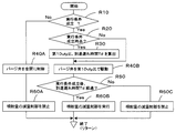
ステップR10にて制御手段は、パージ制御の実行条件が成立しているか否かを判定し、実行条件が成立している場合(Yes)はステップR20に進み、実行条件が成立していない場合(No)はステップR40Aに進む。 In step R10, the control means determines whether or not the purge control execution condition is satisfied, and if the execution condition is satisfied (Yes), the process proceeds to step R20, and if the execution condition is not satisfied ( No) goes to step R40A.
ステップR40Aに進んだ場合、制御手段は、パージ弁を全閉状態に制御してステップR60Aに進む。そしてステップR60Aにて制御手段は、インジェクタからの燃料噴射量の減量制御を禁止し、処理を終了する。 When the process proceeds to Step R40A, the control means controls the purge valve to the fully closed state and proceeds to Step R60A. In step R60A, the control means prohibits the fuel injection amount reduction control from the injector and ends the processing.
ステップR20に進んだ場合、制御手段は、パージ制御の実行条件が成立時点(今回のタイミングが、実行条件が不成立から成立になったタイミング)であるか否かを判定し、成立時点である場合(Yes)はステップR30に進み、成立時点でない場合(No)はステップR40Bに進む。 When the routine proceeds to step R20, the control means determines whether or not the purge control execution condition is satisfied (this timing is the timing when the execution condition is satisfied from the failure), and when it is satisfied. (Yes) proceeds to step R30, and if not (No), the process proceeds to step R40B.
ステップR30に進んだ場合、制御手段は、パージ制御中のパージ弁の開度である第1Duty比(または第1開度)と、到達遅れ時間Tdを算出し、ステップR40Bに進む。なお、到達遅れ時間Tdは、例えば図1におけるクランク回転検出手段26Nにて検出したクランクシャフト26Cの回転数や、吸入空気量検出手段10Sにて検出した吸気の流量や、パージ弁31Vの開度量や、圧力検出手段24Sにて検出した吸気通路23内の圧力、等に基づいて算出される。
When the routine proceeds to step R30, the control means calculates the first duty ratio (or the first opening), which is the opening of the purge valve during purge control, and the arrival delay time Td, and then proceeds to step R40B. The arrival delay time Td is, for example, the rotation speed of the
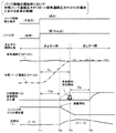
ステップR40Bにて制御手段は、パージ弁を第1Duty比(または第1開度)で駆動し、ステップR50に進む。なお、図4に示す理想状態の動作波形では、パージ弁31Vを第1Duty比で駆動開始したタイミングT1において、逆止弁32Vが開状態であるので、キャニスタからの蒸発燃料の流出が開始される(パージ制御の開始時において、吸気通路圧力P(23)≦中間パージ通路圧力P(32)である場合)。ただし、パージ通路から内燃機関までの距離があるので、流出した蒸発燃料が内燃機関に吸引されるまでには到達遅れ時間Tdだけ時間がかかり、到達遅れ時間Tdが経過したタイミングT2から内燃機関への蒸発燃料流入量が増加している。
In step R40B, the control means drives the purge valve at the first duty ratio (or the first opening), and proceeds to step R50. In the operation waveform in the ideal state shown in FIG. 4, since the
ステップR50にて制御手段は、パージ制御の実行条件が成立後、到達遅れ時間Tdが経過したか否かを判定し、経過している場合(Yes)はステップR60Bに進み、経過していない場合(No)はステップR60Cに進む。 In step R50, the control means determines whether or not the arrival delay time Td has elapsed after the purge control execution condition is satisfied. If yes (Yes), the control means proceeds to step R60B, and has not elapsed. (No) advances to step R60C.
ステップR60Bに進んだ場合、制御手段は、インジェクタからの燃料噴射量の減量制御を実行し、処理を終了する。図4に示す理想状態の動作波形では、到達遅れ時間Tdが経過したタイミングT2からの内燃機関への蒸発燃料流入量の増加分を相殺するように、インジェクタからの燃料の噴射量を減量している。このため、空燃比の変動が適切に抑制され、理論空燃比(λ=1.0)の近傍の状態が維持されている。 When the routine proceeds to step R60B, the control means executes a reduction control of the fuel injection amount from the injector and ends the process. In the operation waveform in the ideal state shown in FIG. 4, the amount of fuel injected from the injector is reduced so as to offset the increase in the amount of fuel vapor flowing into the internal combustion engine from the timing T2 when the arrival delay time Td has elapsed. Yes. For this reason, fluctuations in the air-fuel ratio are appropriately suppressed, and a state in the vicinity of the theoretical air-fuel ratio (λ = 1.0) is maintained.
ステップR60Cに進んだ場合、制御手段は、インジェクタからの燃料噴射量の減量制御を禁止し、処理を終了する。 When the process proceeds to step R60C, the control unit prohibits the fuel injection amount reduction control from the injector and ends the process.
●[パージ制御の開始時において、中間パージ通路圧力<吸気通路圧力の場合(図6)]
図4に示した状態は、パージ制御の開始時に逆止弁が開状態である理想状態であるが、パージ制御の開始時において、吸気通路圧力P(23)>中間パージ通路圧力である場合、中間パージ通路内には負圧が密閉されている。この場合、図5に示すフローチャートのステップR40Bにてパージ弁を第1Duty比(または第1開度)で駆動を開始しても、逆止弁はまだ閉じている(図6中のタイミングT1参照)。このタイミングT1の時点から、中間パージ通路内には、キャニスタに導入された大気が、パージ弁の側から徐々に流れ込み、中間パージ通路内の圧力が徐々に上昇していく(図6中のタイミングT1〜タイミングT3)。
● [When purge control starts, intermediate purge passage pressure <intake passage pressure (Fig. 6)]
The state shown in FIG. 4 is an ideal state in which the check valve is open at the start of the purge control, but when the intake passage pressure P (23)> the intermediate purge passage pressure at the start of the purge control, A negative pressure is sealed in the intermediate purge passage. In this case, even if the purge valve starts to be driven at the first duty ratio (or the first opening) in step R40B of the flowchart shown in FIG. 5, the check valve is still closed (see timing T1 in FIG. 6). ). From the timing T1, the air introduced into the canister gradually flows into the intermediate purge passage from the purge valve side, and the pressure in the intermediate purge passage gradually increases (timing in FIG. 6). T1 to timing T3).
なお、図6の例では、パージ弁を第1Duty比で駆動を開始した後、到達遅れ時間Tdを経過しても、まだ逆止弁が閉じた状態である例を示している。従って、この状態でインジェクタの燃料噴射量の減量を行うと、まだ蒸発燃料が内燃機関に到達していないので、燃料が不足し、空燃比が大きくなる側に変動する(空気過剰(リーン)の側に変動する)ので、理論空燃比に対して所定範囲内から外れる可能性があり、好ましくない。 In the example of FIG. 6, the check valve is still closed even after the arrival delay time Td has elapsed after the purge valve starts to be driven at the first duty ratio. Therefore, if the fuel injection amount of the injector is reduced in this state, the evaporated fuel has not yet reached the internal combustion engine, so that the fuel becomes insufficient and the air-fuel ratio fluctuates to the side where the air-fuel ratio increases (lean air). Therefore, there is a possibility that the stoichiometric air-fuel ratio falls outside the predetermined range, which is not preferable.
なお、図6に示すように、中間パージ通路圧力P(32)≧吸気通路圧力P(23)となったタイミングT3にて逆止弁32Vが開くので、タイミングT3から到達遅れ時間Tdが経過したタイミングT4から、内燃機関への蒸発燃料流入量が増加している。この図6中におけるタイミングT1〜タイミングT3までの逆止弁32Vが閉じた状態の時間が、上述したタイムラグである。
As shown in FIG. 6, since the
以降、このタイムラグを考慮したパージ制御、タイムラグをより短くするパージ制御等の第1〜第5の実施の形態について順に説明する。 Hereinafter, first to fifth embodiments such as purge control considering the time lag and purge control for shortening the time lag will be described in order.
●[第1の実施の形態の処理手順(図8)と、動作波形(図7)]
図8に示すフローチャートと、図7に示す動作波形を用いて、蒸発燃料供給装置の第1の実施の形態について説明する。制御手段は、従来の処理手順と同様のタイミングにて、図8に示す処理を起動する。
[Processing procedure of the first embodiment (FIG. 8) and operation waveform (FIG. 7)]
The first embodiment of the evaporated fuel supply apparatus will be described using the flowchart shown in FIG. 8 and the operation waveforms shown in FIG. The control means starts the process shown in FIG. 8 at the same timing as the conventional process procedure.
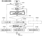
ステップS10にて制御手段は、パージ制御の実行条件が成立しているか否かを判定し、実行条件が成立している場合(Yes)はステップS20に進み、実行条件が成立していない場合(No)はステップS50Aに進む。 In step S10, the control unit determines whether or not the purge control execution condition is satisfied. If the execution condition is satisfied (Yes), the process proceeds to step S20, and if the execution condition is not satisfied ( No) goes to step S50A.
ステップS50Aに進んだ場合、制御手段は、パージ弁を全閉状態に制御してステップS70Aに進む。そしてステップS70Aにて制御手段は、インジェクタからの燃料噴射量の減量制御を禁止し、処理を終了する。 When the process proceeds to step S50A, the control means controls the purge valve to the fully closed state and proceeds to step S70A. In step S70A, the control means prohibits the fuel injection amount reduction control from the injector and ends the processing.
ステップS20に進んだ場合、制御手段は、パージ制御の実行条件が成立時点(今回のタイミングが、実行条件が不成立から成立になったタイミング)であるか否かを判定し、成立時点である場合(Yes)はステップS30に進み、成立時点でない場合(No)はステッS40に進む。 When the process proceeds to step S20, the control means determines whether or not the purge control execution condition is satisfied (this timing is the timing when the execution condition is satisfied after the execution condition is not satisfied). If (Yes), the process proceeds to step S30, and if it is not established (No), the process proceeds to step S40.
ステップS30に進んだ場合、制御手段は、パージ制御中の通常のパージ弁の開度である第1Duty比(または第1開度)と、パージ制御の開始時に一時的に用いる第2Duty比(または第2開度)と、所定時間Tpと、到達遅れ時間Td(所定到達遅れ時間に相当)を算出し、ステップS40に進む。なお、第1Duty比(または第1開度)は、パージ制御を実行するための通常の開度(本来の開度)である。また、第2Duty比(または第2開度)は、第1Duty比(または第1開度)よりも大きな開度であって一時的にパージ弁の開度を大きくするための開度である。また所定時間Tpは、図7に示すように、中間パージ通路圧力P(32)が吸気通路圧力P(23)以上となるまでに要する時間(タイムラグ)であって、吸気通路圧力P(23)、中間パージ通路圧力P(32)、パージ弁の開度量、等に基づいて算出される。また到達遅れ時間Tdは、例えば図1におけるクランク回転検出手段26Nにて検出したクランクシャフト26Cの回転数や、吸入空気量検出手段10Sにて検出した吸気の流量や、パージ弁31Vの開度量や、圧力検出手段24Sにて検出した吸気通路23内の圧力、等に基づいて算出される。
When the process proceeds to step S30, the control means performs the first duty ratio (or the first opening) that is the opening of the normal purge valve during the purge control and the second duty ratio (or the first duty ratio that is temporarily used at the start of the purge control). 2nd opening degree), predetermined time Tp, and arrival delay time Td (equivalent to predetermined arrival delay time) are calculated, and it progresses to step S40. The first duty ratio (or the first opening) is a normal opening (original opening) for executing the purge control. The second duty ratio (or the second opening) is an opening larger than the first duty ratio (or the first opening) and is an opening for temporarily increasing the opening of the purge valve. Further, as shown in FIG. 7, the predetermined time Tp is a time (time lag) required until the intermediate purge passage pressure P (32) becomes equal to or higher than the intake passage pressure P (23), and the intake passage pressure P (23). , Based on the intermediate purge passage pressure P (32), the opening amount of the purge valve, and the like. Further, the arrival delay time Td is, for example, the rotational speed of the
ステップS40にて制御手段は、パージ制御の実行条件が成立後、所定時間Tpが経過したか否かを判定し、経過している場合(Yes)はステップS50Bに進み、経過していない場合(No)はステップS50Cに進む。 In step S40, the control means determines whether or not a predetermined time Tp has elapsed after the purge control execution condition is satisfied. If yes (Yes), the control means proceeds to step S50B, and if not ( No) goes to step S50C.
ステップS50Cに進んだ場合、制御手段は、パージ弁を第2Duty比(または第2開度)で駆動し、より大きな開度でタイムラグ(図7中のタイミングT1〜T3(1)までの長さ)がより短くなるように制御し、ステップS70Cに進む。なお、第1Duty比(または第1開度)よりも大きな第2Duty比(または第2開度)でパージ弁を開くことで、図6の例に示したタイムラグ(タイミングT1〜T3の長さ)よりも、図7の例に示したタイムラグ(タイミングT1〜T3(1)の長さ)を、より短くすることができる。なお図7の例では、所定時間Tpが経過したタイミングT3(1)にて、中間パージ通路圧力P(32)≧吸気通路圧力P(23)となり、逆止弁が閉状態から開状態に変化した例を示している。 When the process proceeds to step S50C, the control means drives the purge valve at the second duty ratio (or the second opening), and the time lag (the length from timing T1 to T3 (1) in FIG. 7) with a larger opening. ) To be shorter, and the process proceeds to step S70C. Note that the time lag shown in the example of FIG. 6 (the length of timings T1 to T3) is established by opening the purge valve at a second duty ratio (or second opening) larger than the first duty ratio (or first opening). Instead, the time lag shown in the example of FIG. 7 (the length of the timings T1 to T3 (1)) can be further shortened. In the example of FIG. 7, at the timing T3 (1) when the predetermined time Tp has elapsed, the intermediate purge passage pressure P (32) ≧ the intake passage pressure P (23), and the check valve changes from the closed state to the open state. An example is shown.
ステップS70Cでは制御手段は、インジェクタからの燃料噴射量の減量制御を禁止し、処理を終了する。 In step S70C, the control means prohibits the fuel injection amount reduction control from the injector and ends the process.
ステップS50Bに進んだ場合(この場合は図7中のタイミングT3(1)以降の期間であるので)、制御手段は、パージ弁を第1Duty比(または第1開度)で駆動し、ステップS60に進む。 When the process proceeds to step S50B (in this case, it is a period after timing T3 (1) in FIG. 7), the control means drives the purge valve at the first duty ratio (or the first opening), and step S60. Proceed to
ステップS60にて制御手段は、所定時間Tpの経過時点から(タイミングT3(1)の時点から)、到達遅れ時間Tdが経過したか否かを判定し、経過している場合(Yes)はステップS70Bに進み、経過していない場合(No)はステップS70Cに進む。 In step S60, the control means determines whether or not the arrival delay time Td has elapsed since the elapse of the predetermined time Tp (from the time of timing T3 (1)). The process proceeds to S70B, and if it has not elapsed (No), the process proceeds to Step S70C.
ステップS70Bに進んだ場合、制御手段は、インジェクタからの燃料噴射量の減量制御を実行し、処理を終了する。図7に示す動作波形では、パージ制御の実行条件が成立後、タイムラグ(所定時間Tp)と到達遅れ時間Tdとが経過したタイミングT4(1)からの内燃機関への蒸発燃料流入量の増加分を相殺するように、インジェクタからの燃料の噴射量を減量している。このため、空燃比の変動が適切に抑制され、理論空燃比(λ=1.0)の近傍の状態が維持されている。 When it progresses to step S70B, a control means performs reduction | decrease control of the fuel injection quantity from an injector, and complete | finishes a process. In the operation waveform shown in FIG. 7, after the execution condition of the purge control is satisfied, the amount of increase in the amount of fuel vapor flowing into the internal combustion engine from the timing T4 (1) when the time lag (predetermined time Tp) and the arrival delay time Td have elapsed. The fuel injection amount from the injector is reduced so as to cancel out the above. For this reason, fluctuations in the air-fuel ratio are appropriately suppressed, and a state in the vicinity of the theoretical air-fuel ratio (λ = 1.0) is maintained.
上記の例では、図7中においてパージ制御の実行を開始してから逆止弁が開くまでのタイミングT1〜タイミングT3(1)までの間、パージ弁を第2Duty比(または第2開度)で制御する例を示したが、タイミングT1〜タイミングT3(1)までの間において任意の期間の間(所定条件を満足する期間の間)、パージ弁を第2Duty比(または第2開度)で制御するようにしてもよい。 In the above example, the purge valve is set to the second duty ratio (or the second opening) from the timing T1 to the timing T3 (1) from the start of execution of the purge control to the opening of the check valve in FIG. However, the purge valve is set to the second duty ratio (or the second opening) during an arbitrary period (during a period satisfying a predetermined condition) between timing T1 and timing T3 (1). You may make it control by.
また、例えば第2Duty比(または第2開度)は、パージ弁の最大開度となる開度であってもよいし、吸気通路圧力P(23)と中間パージ通路圧力P(32)との圧力差に基づいて第2Duty比(または第2開度)を算出する(調整する)ようにしてもよい。 Further, for example, the second duty ratio (or the second opening) may be an opening that is the maximum opening of the purge valve, or the intake passage pressure P (23) and the intermediate purge passage pressure P (32). The second duty ratio (or the second opening) may be calculated (adjusted) based on the pressure difference.
また、ステップS40にて所定時間Tpの経過を判定する代わりに、中間パージ通路圧力P(32)が吸気通路圧力P(23)よりも高くなった場合にステップS50Bに進む(第2Duty比から第1Duty比に切り替える)ようにしてもよい。また、ステップS40にて所定時間Tpの経過を判定する代わりに、吸気通路圧力P(23)と中間パージ通路圧力P(32)との圧力差が所定圧力差以下となった場合にステップS50Bに進む(第2Duty比から第1Duty比に切り替える)ようにしてもよい。この場合は、パージ弁を第2Duty比(または第2開度)から第1Duty比(または第1開度)に切り替えたタイミングから、到達遅れ時間の計測を開始する。 Further, instead of determining whether the predetermined time Tp has elapsed in step S40, the process proceeds to step S50B when the intermediate purge passage pressure P (32) becomes higher than the intake passage pressure P (23) (from the second duty ratio to the first duty ratio). (Switch to 1 Duty ratio). Further, instead of determining whether the predetermined time Tp has elapsed in step S40, if the pressure difference between the intake passage pressure P (23) and the intermediate purge passage pressure P (32) is equal to or smaller than the predetermined pressure difference, the process proceeds to step S50B. It is also possible to proceed (switch from the second duty ratio to the first duty ratio). In this case, the measurement of the arrival delay time is started from the timing when the purge valve is switched from the second duty ratio (or second opening) to the first duty ratio (or first opening).
以上、図7、図8に示す第1の実施の形態では、図5、図6に示す従来と比較して、インジェクタからの燃料噴射量の減量制御の実行時における空燃比の変動が抑制されており、より良好なパージ制御を実行することができる。また、パージ制御の実行を開始してから逆止弁が開くまでの時間であるタイムラグ(図6中のタイミングT1〜T3、図7中のタイミングT1〜T3(1))を、より短くすることができる。 As described above, in the first embodiment shown in FIGS. 7 and 8, fluctuations in the air-fuel ratio during the execution of the fuel injection amount reduction control from the injector are suppressed as compared with the conventional example shown in FIGS. Therefore, better purge control can be performed. Further, the time lag (timing T1 to T3 in FIG. 6, timing T1 to T3 (1) in FIG. 7) from the start of execution of purge control to the opening of the check valve is made shorter. Can do.
なお、パージ制御の開始時に中間パージ通路圧力が吸気通路内の圧力よりも高い場合(あるいは同じ場合)は、逆止弁が既に開いており所定時間Tpがゼロとなるので、この場合は、パージ弁を第2Duty比(または第2開度)で駆動することを省略できる。 If the intermediate purge passage pressure is higher (or the same) than the pressure in the intake passage at the start of the purge control, the check valve is already open and the predetermined time Tp becomes zero. Driving the valve at the second duty ratio (or the second opening) can be omitted.
●[第2の実施の形態の処理手順(図10)と、動作波形(図9)]
次に図10に示すフローチャートと、図9に示す動作波形を用いて、蒸発燃料供給装置の第2の実施の形態について説明する。なお、図7中のタイミングT3(1)を起点としてタイミングT4(1)にて燃料噴射量の減量を開始する第1の実施の形態に対して、第2の実施の形態では、図9中のタイミングT1を起点としてタイミングT4(2)にて燃料噴射量の減量を開始する点が異なる。以下、この相違点について主に説明する。
[Processing procedure of the second embodiment (FIG. 10) and operation waveform (FIG. 9)]
Next, a second embodiment of the evaporated fuel supply apparatus will be described using the flowchart shown in FIG. 10 and the operation waveforms shown in FIG. Note that, in the second embodiment, the second embodiment starts the decrease in the fuel injection amount at the timing T4 (1) starting from the timing T3 (1) in FIG. The difference is that the fuel injection amount starts to be reduced at timing T4 (2) starting from the timing T1. Hereinafter, this difference will be mainly described.
図10に示すフローチャートは、図8に示すフローチャートに対して、ステップS30がステップS32に変更され、ステップS60がステップS62に変更されている点が異なる。 The flowchart shown in FIG. 10 differs from the flowchart shown in FIG. 8 in that step S30 is changed to step S32 and step S60 is changed to step S62.
ステップS32に進んだ場合、制御手段は、パージ制御中の通常のパージ弁の開度である第1Duty比(または第1開度)と、パージ制御の開始時に一時的に用いる第2Duty比(または第2開度)と、所定時間Tpと、総合遅れ時間Tddを算出し、ステップS40に進む。なお、総合遅れ時間Tdd=所定時間Tp+到達遅れ時間Tdである。また、到達遅れ時間Tdの求め方は、第1の実施の形態と同じである。 When the process proceeds to step S32, the control means, the first duty ratio (or the first opening) that is the opening of the normal purge valve during the purge control and the second duty ratio (or the first duty ratio that is temporarily used at the start of the purge control) (or 2nd opening degree), predetermined time Tp, and total delay time Tdd are calculated, and it progresses to step S40. Note that the total delay time Tdd = predetermined time Tp + arrival delay time Td. The method for obtaining the arrival delay time Td is the same as in the first embodiment.
ステップS62にて制御手段は、パージ制御の実行条件の成立時点から(タイミングT1の時点から)、総合遅れ時間Tddが経過したか否かを判定し、経過している場合(Yes)はステップS70Bに進み、経過していない場合(No)はステップS70Cに進む。なお、ステップS32、S62以外のステップの処理は、第1の実施の形態と同じであるので説明を省略する。 In step S62, the control means determines whether or not the total delay time Tdd has elapsed from the time when the purge control execution condition is satisfied (from time T1). If yes (step S70B). If it has not elapsed (No), the process proceeds to step S70C. In addition, since the process of steps other than step S32 and S62 is the same as 1st Embodiment, description is abbreviate | omitted.
第2の実施の形態は、第1の実施の形態に対して、インジェクタからの燃料噴射量の減量制御を開始するタイミングT4(2)の計時の起点を、タイミングT3(1)(図7参照)からタイミングT1(図9参照)に変更したのみである。従って、第2の実施の形態の動作波形(図9)は、第1の実施の形態の動作波形(図7)と同じである。また、インジェクタからの燃料噴射量の減量制御の実行時における空燃比の変動が抑制される点、パージ制御の実行を開始してから逆止弁が開くまでの時間であるタイムラグをより短くできる点も第1の実施の形態と同じである。 Compared to the first embodiment, the second embodiment uses a timing T3 (1) (see FIG. 7) as a starting point for timing T4 (2) at which the fuel injection amount reduction control from the injector is started. ) To timing T1 (see FIG. 9). Therefore, the operation waveform (FIG. 9) of the second embodiment is the same as the operation waveform (FIG. 7) of the first embodiment. In addition, the fluctuation of the air-fuel ratio during the execution of the fuel injection amount reduction control from the injector is suppressed, and the time lag that is the time from the start of the purge control to the opening of the check valve can be shortened. Is the same as that of the first embodiment.
また、第1の実施の形態と同様に、タイミングT1〜タイミングT3(2)までの間において任意の期間の間(所定条件を満足する期間の間)、パージ弁を第2Duty比(または第2開度)で制御するようにしてもよい。また、例えば第2Duty比(または第2開度)は、パージ弁の最大開度となる開度であってもよいし、吸気通路圧力P(23)と中間パージ通路圧力P(32)との圧力差に基づいて第2Duty比(または第2開度)を算出する(調整する)ようにしてもよい。 Similarly to the first embodiment, the purge valve is set to the second duty ratio (or the second duty ratio) during an arbitrary period (a period satisfying a predetermined condition) between the timing T1 and the timing T3 (2). You may make it control by an opening degree. Further, for example, the second duty ratio (or the second opening) may be an opening that is the maximum opening of the purge valve, or the intake passage pressure P (23) and the intermediate purge passage pressure P (32). The second duty ratio (or the second opening) may be calculated (adjusted) based on the pressure difference.
また、第1の実施の形態と同様に、ステップS40にて所定時間Tpの経過を判定する代わりに、中間パージ通路圧力P(32)が吸気通路圧力P(23)よりも高くなった場合にステップS50Bに進む(第2Duty比から第1Duty比に切り替える)ようにしてもよい。また、ステップS40にて所定時間Tpの経過を判定する代わりに、吸気通路圧力P(23)と中間パージ通路圧力P(32)との圧力差が所定圧力差以下となった場合にステップS50Bに進む(第2Duty比から第1Duty比に切り替える)ようにしてもよい。 Similarly to the first embodiment, when the intermediate purge passage pressure P (32) becomes higher than the intake passage pressure P (23) instead of determining whether the predetermined time Tp has elapsed in step S40. The process may proceed to Step S50B (switch from the second duty ratio to the first duty ratio). Further, instead of determining whether the predetermined time Tp has elapsed in step S40, if the pressure difference between the intake passage pressure P (23) and the intermediate purge passage pressure P (32) is equal to or smaller than the predetermined pressure difference, the process proceeds to step S50B. It is also possible to proceed (switch from the second duty ratio to the first duty ratio).
また、総合遅れ時間Tdd=所定時間Tp+到達遅れ時間Tdであるので、総合遅れ時間Tddは、到達遅れ時間Tdよりも長い。さらに、吸気通路圧力と中間パージ通路圧力との圧力差が大きくなるにつれて総合遅れ時間が長くなるように設定される。また、この総合遅れ時間を、新たな到達遅れ時間(パージ制御を開始時から内燃機関に蒸発燃料が到達するまでの遅れ時間)とみなすようにしてもよい。 Further, since the total delay time Tdd = the predetermined time Tp + the arrival delay time Td, the total delay time Tdd is longer than the arrival delay time Td. Further, the total delay time is set longer as the pressure difference between the intake passage pressure and the intermediate purge passage pressure becomes larger. Further, this total delay time may be regarded as a new arrival delay time (a delay time from when purge control is started until the evaporated fuel reaches the internal combustion engine).
なお、パージ制御の開始時に中間パージ通路圧力が吸気通路内の圧力よりも高い場合(あるいは同じ場合)は、逆止弁が既に開いており所定時間Tpがゼロとなるので、この場合は、パージ弁を第2Duty比(または第2開度)で駆動することを省略できる。 If the intermediate purge passage pressure is higher (or the same) than the pressure in the intake passage at the start of the purge control, the check valve is already open and the predetermined time Tp becomes zero. Driving the valve at the second duty ratio (or the second opening) can be omitted.
●[第3の実施の形態の処理手順(図12)と、動作波形(図11)]
次に図12に示すフローチャートと、図11に示す動作波形を用いて、蒸発燃料供給装置の第3の実施の形態について説明する。なお、図7中のタイミングT1を起点として所定時間Tp+到達遅れ時間Tdを経過したタイミングT4(1)にて燃料噴射量の減量を開始する第1の実施の形態に対して、第3の実施の形態では、図9中のタイミングT1を起点として到達遅れ時間Tdを経過したタイミングT3(3)にて燃料噴射量の減量を開始する点が異なる。以下、この相違点について主に説明する。
[Processing procedure of the third embodiment (FIG. 12) and operation waveform (FIG. 11)]
Next, a third embodiment of the evaporated fuel supply apparatus will be described using the flowchart shown in FIG. 12 and the operation waveforms shown in FIG. Note that the third embodiment is different from the first embodiment in which the reduction of the fuel injection amount is started at the timing T4 (1) when the predetermined time Tp + the arrival delay time Td has elapsed from the timing T1 in FIG. This embodiment is different in that the fuel injection amount starts to be reduced at timing T3 (3) when the arrival delay time Td has elapsed from the timing T1 in FIG. Hereinafter, this difference will be mainly described.
図12に示すフローチャートは、図8に示すフローチャートに対して、ステップS60がステップS63に変更されている点が異なる。 The flowchart shown in FIG. 12 differs from the flowchart shown in FIG. 8 in that step S60 is changed to step S63.
ステップS63にて制御手段は、パージ制御の実行条件の成立時点から(タイミングT1の時点から)、到達遅れ時間Tdが経過したか否かを判定し、経過している場合(Yes)はステップS70Bに進み、経過していない場合(No)はステップS70Cに進む。なお、ステップS63以外のステップの処理は、第1の実施の形態と同じであるので説明を省略する。 In step S63, the control means determines whether or not the arrival delay time Td has elapsed from the time when the purge control execution condition is satisfied (from the timing T1). If yes (step S70B) If it has not elapsed (No), the process proceeds to step S70C. In addition, since the process of steps other than step S63 is the same as 1st Embodiment, description is abbreviate | omitted.
第3の実施の形態は、第1の実施の形態に対して、インジェクタからの燃料噴射量の減量制御を開始するタイミングT3(3)を、所定時間Tp(タイムラグ)+到達遅れ時間Tdから、到達遅れ時間Tdのみに変更している。従って、図11の動作波形に示すように、内燃機関への蒸発燃料の流入が開始されるタイミングT4(3)よりも、やや手前となるタイミングT3(3)から燃料噴射量の減量が開始される。そのため、図11に示すように、タイミングT3(3)からタイミングT4(3)及びタイミングT4(3)以降の所定期間では、空燃比がやや空気過剰の側に変動する。しかし、パージ制御の開始時において、パージ弁を、より大きな開度の第2Duty比(または第2開度)に制御することで、逆止弁が開くまでのタイムラグ(タイミングT1〜タイミングT2(3)までの期間)を、より短くしているので、図6に示す従来の動作波形と比較して、空燃比の値(図中の高さ)と、空燃比が空気過剰の側に変動している時間(図中の幅)を、より短くすることが可能であり、理論空燃比に対して所定範囲内に収めることが可能である。 In the third embodiment, the timing T3 (3) for starting the reduction control of the fuel injection amount from the injector is compared with the first embodiment from the predetermined time Tp (time lag) + the arrival delay time Td. Only the arrival delay time Td is changed. Therefore, as shown in the operation waveform of FIG. 11, the fuel injection amount starts to be reduced at a timing T3 (3) slightly before the timing T4 (3) at which the inflow of the evaporated fuel into the internal combustion engine is started. The Therefore, as shown in FIG. 11, the air-fuel ratio fluctuates slightly to the excess air side during a predetermined period from timing T3 (3) to timing T4 (3) and timing T4 (3). However, at the start of the purge control, the purge valve is controlled to the second duty ratio (or the second opening) with a larger opening so that the time lag until the check valve opens (timing T1 to timing T2 (3 )) Is shorter, so that the air-fuel ratio value (height in the figure) and the air-fuel ratio fluctuate to the excess air side compared to the conventional operation waveform shown in FIG. The time (width in the figure) can be shortened and can be within a predetermined range with respect to the theoretical air-fuel ratio.
また、第1の実施の形態と同様に、タイミングT1〜タイミングT2(3)までの間において任意の期間の間(所定条件を満足する期間の間)、パージ弁を第2Duty比(または第2開度)で制御するようにしてもよい。また、例えば第2Duty比(または第2開度)は、パージ弁の最大開度となる開度であってもよいし、吸気通路圧力P(23)と中間パージ通路圧力P(32)との圧力差に基づいて第2Duty比(または第2開度)を算出する(調整する)ようにしてもよい。 Further, as in the first embodiment, the purge valve is set to the second duty ratio (or the second duty ratio) for an arbitrary period (a period satisfying a predetermined condition) between the timing T1 and the timing T2 (3). You may make it control by an opening degree. Further, for example, the second duty ratio (or the second opening) may be an opening that is the maximum opening of the purge valve, or the intake passage pressure P (23) and the intermediate purge passage pressure P (32). The second duty ratio (or the second opening) may be calculated (adjusted) based on the pressure difference.
また、第1の実施の形態と同様に、ステップS40にて所定時間Tpの経過を判定する代わりに、中間パージ通路圧力P(32)が吸気通路圧力P(23)よりも高くなった場合にステップS50Bに進む(第2Duty比から第1Duty比に切り替える)ようにしてもよい。また、ステップS40にて所定時間Tpの経過を判定する代わりに、吸気通路圧力P(23)と中間パージ通路圧力P(32)との圧力差が所定圧力差以下となった場合にステップS50Bに進む(第2Duty比から第1Duty比に切り替える)ようにしてもよい。 Similarly to the first embodiment, when the intermediate purge passage pressure P (32) becomes higher than the intake passage pressure P (23) instead of determining whether the predetermined time Tp has elapsed in step S40. The process may proceed to Step S50B (switch from the second duty ratio to the first duty ratio). Further, instead of determining whether the predetermined time Tp has elapsed in step S40, if the pressure difference between the intake passage pressure P (23) and the intermediate purge passage pressure P (32) is equal to or smaller than the predetermined pressure difference, the process proceeds to step S50B. It is also possible to proceed (switch from the second duty ratio to the first duty ratio).
なお、パージ制御の開始時に中間パージ通路圧力が吸気通路内の圧力よりも高い場合(あるいは同じ場合)は、逆止弁が既に開いており所定時間Tpがゼロとなるので、この場合は、パージ弁を第2Duty比(または第2開度)で駆動することを省略できる。 If the intermediate purge passage pressure is higher (or the same) than the pressure in the intake passage at the start of the purge control, the check valve is already open and the predetermined time Tp becomes zero. Driving the valve at the second duty ratio (or the second opening) can be omitted.
●[第4の実施の形態の処理手順(図14)と、動作波形(図13)]
次に図14に示すフローチャートと、図13に示す動作波形を用いて、蒸発燃料供給装置の第4の実施の形態について説明する。なお、図9中のタイミングT1〜タイミングT3(2)ではパージ弁を第2Duty比で駆動する第2の実施の形態に対して、第4の実施の形態では、図13中のタイミングT1〜タイミングT3(4)ではパージ弁を第1Duty比で駆動するので所定時間Tpが長くなっている点が異なる。以下、この相違点について主に説明する。
[Processing procedure of the fourth embodiment (FIG. 14) and operation waveform (FIG. 13)]
Next, a fourth embodiment of the evaporated fuel supply apparatus will be described using the flowchart shown in FIG. 14 and the operation waveforms shown in FIG. In the fourth embodiment, the timing T1 to timing T3 in FIG. 13 is compared with the second embodiment in which the purge valve is driven at the second duty ratio at timing T1 to timing T3 (2) in FIG. In T3 (4), since the purge valve is driven at the first duty ratio, the predetermined time Tp is different. Hereinafter, this difference will be mainly described.
図14に示すフローチャートは、図10に示すフローチャートに対して、ステップS32がステップS34に変更されている点と、ステップS40、S50Cが省略されている点が異なる。 The flowchart shown in FIG. 14 differs from the flowchart shown in FIG. 10 in that step S32 is changed to step S34 and that steps S40 and S50C are omitted.
ステップS34に進んだ場合、制御手段は、パージ制御中の通常のパージ弁の開度である第1Duty比(または第1開度)と、総合遅れ時間Tddを算出し、ステップS50Bに進む。また、総合遅れ時間Tddの求め方は、第2の実施の形態と同じであるが、パージ制御の開始時におけるパージ弁の開度が、第1Duty比であるので、第2の実施の形態にて求めた総合遅れ時間Tddよりも、第4の実施の形態にて求めた総合遅れ時間Tddのほうが長い。なお、その他のステップの処理は、第2の実施の形態と同じであるので説明を省略する。 When the process proceeds to step S34, the control unit calculates the first duty ratio (or the first opening) that is the opening degree of the normal purge valve during the purge control and the total delay time Tdd, and the process proceeds to step S50B. The method for obtaining the total delay time Tdd is the same as that in the second embodiment. However, since the opening of the purge valve at the start of the purge control is the first duty ratio, the second embodiment is used. The total delay time Tdd determined in the fourth embodiment is longer than the total delay time Tdd determined in this way. Note that the processing of other steps is the same as that of the second embodiment, and thus description thereof is omitted.
第4の実施の形態は、第2の実施の形態に対して総合遅れ時間Tddが長くなるが、第3の実施の形態のような燃料噴射量の減量開始タイミングと内燃機関への蒸発燃料の流入開始タイミングとの「ずれ」が生じないので、空燃比の変動をより抑制することができる。 In the fourth embodiment, the total delay time Tdd is longer than in the second embodiment, but the fuel injection amount reduction start timing and the evaporated fuel to the internal combustion engine as in the third embodiment are increased. Since there is no “deviation” from the inflow start timing, fluctuations in the air-fuel ratio can be further suppressed.
また、ステップS34にて、第1Duty比(または第1開度)と、所定時間Tp(所定待ち時間に相当)と、到達遅れ時間Tdを算出し、ステップS62にて、パージ制御の実行条件が成立時点から(タイミングT1の時点から)、所定時間Tpが経過した後、到達遅れ時間Tdが経過したか否かを判定し、経過している場合(Yes)はステップS70Bに進み、経過していない場合(No)はステップS70Cに進むようにしてもよい。あるいは、ステップS62にて、中間パージ通路圧力P(32)が吸気通路圧力P(23)よりも高くなった後(所定待ち時間の経過を待つことなく)、到達遅れ時間Tdが経過したか否かを判定するようにしてもよい。あるいは、ステップS62にて、吸気通路圧力P(23)と中間パージ通路圧力P(32)との圧力差が所定圧力差以下となった後(所定待ち時間の経過を待つことなく)、到達遅れ時間Tdが経過したか否かを判定するようにしてもよい。 In step S34, a first duty ratio (or first opening), a predetermined time Tp (corresponding to a predetermined waiting time), and an arrival delay time Td are calculated. In step S62, the execution condition of the purge control is determined. From the time of establishment (from the time of timing T1), it is determined whether or not the arrival delay time Td has elapsed after the lapse of the predetermined time Tp, and if it has elapsed (Yes), the process proceeds to step S70B. If not (No), the process may proceed to step S70C. Alternatively, whether or not the arrival delay time Td has elapsed after the intermediate purge passage pressure P (32) becomes higher than the intake passage pressure P (23) (without waiting for the elapse of a predetermined waiting time) in step S62. You may make it determine. Alternatively, after the pressure difference between the intake passage pressure P (23) and the intermediate purge passage pressure P (32) becomes equal to or smaller than the predetermined pressure difference (without waiting for the elapse of the predetermined waiting time) in step S62, the arrival delay is reached. You may make it determine whether time Td passed.
なお、パージ制御の開始時に中間パージ通路圧力が吸気通路内の圧力よりも高い場合(あるいは同じ場合)は、逆止弁が既に開いており所定時間Tpがゼロとなる。 If the intermediate purge passage pressure is higher than (or the same as) the pressure in the intake passage at the start of purge control, the check valve is already open and the predetermined time Tp is zero.
●[第5の実施の形態の処理手順(図16)と、動作波形(図15)]
次に図16に示すフローチャートと、図15に示す動作波形を用いて、蒸発燃料供給装置の第5の実施の形態について説明する。第5の実施の形態は、第1の実施の形態に対して、パージ制御の実行条件の成立を予測し、パージ制御の実行条件が成立してパージ制御を実行する直前で、前もってパージ弁を第2Duty比で駆動して、中間パージ通路内の圧力を上昇させることで、パージ制御の実行を開始時点で逆止弁が開くようにしている点が異なる。以下、図16に示すフローチャートを用いて処理手順を説明する。制御手段は、従来の処理手順と同様のタイミングにて、図16に示す処理を起動する。
[Processing procedure of the fifth embodiment (FIG. 16) and operation waveform (FIG. 15)]
Next, a fifth embodiment of the evaporated fuel supply apparatus will be described using the flowchart shown in FIG. 16 and the operation waveforms shown in FIG. Compared to the first embodiment, the fifth embodiment predicts that the purge control execution condition is satisfied, and immediately before the purge control is executed when the purge control execution condition is satisfied, the purge valve is set in advance. The difference is that the check valve is opened at the start of execution of purge control by driving at the second duty ratio and increasing the pressure in the intermediate purge passage. Hereinafter, the processing procedure will be described with reference to the flowchart shown in FIG. The control means starts the process shown in FIG. 16 at the same timing as the conventional process procedure.
ステップS110にて制御手段は、パージ制御の実行条件が成立しているか否かを判定し、実行条件が成立している場合(Yes)はステップS160に進み、実行条件が成立していない場合(No)はステップS115に進む。 In step S110, the control means determines whether or not the purge control execution condition is satisfied. If the execution condition is satisfied (Yes), the process proceeds to step S160, and if the execution condition is not satisfied ( No) goes to step S115.
ステップS115に進んだ場合、制御手段は、現時点より先の時点においてパージ制御の実行条件が満足されるか否かを予測し、先の時点で満足されると予測した場合(Yes)はステップS120に進み、予測されなかった場合(No)はステップS145Aに進む。例えば、車両の速度の変動範囲が所定範囲、かつユーザのアクセルペダルの踏込量の変動範囲が所定範囲、の状態が30秒間継続した際に、パージ制御の実行条件が満足される場合、この場合では、先の時点でパージ制御の実行条件が満足されるか否かを予測することができる(例えば、現時点から20秒後に実行条件が成立する、等の予測をすることができる)。 When the process proceeds to step S115, the control unit predicts whether or not the purge control execution condition is satisfied at a time point earlier than the current time. When the control unit predicts that the purge control execution condition is satisfied at the previous time point (Yes), step S120 is performed. If not predicted (No), the process proceeds to step S145A. For example, in this case, the purge control execution condition is satisfied when the vehicle speed variation range is within a predetermined range and the user's accelerator pedal depression range is within a predetermined range for 30 seconds. Then, it can be predicted whether or not the purge control execution condition is satisfied at the previous time (for example, it can be predicted that the execution condition will be satisfied 20 seconds after the current time).
ステップS145Aに進んだ場合、制御手段は、パージ弁を全閉状態に制御してステップS190Aに進む。そしてステップS190Aにて制御手段は、インジェクタからの燃料噴射量の減量制御を禁止し、処理を終了する。 When the process proceeds to step S145A, the control means controls the purge valve to the fully closed state and proceeds to step S190A. In step S190A, the control unit prohibits the fuel injection amount reduction control from the injector and ends the process.
ステップS120に進んだ場合、制御手段は、パージ制御を開始する直前のプレ駆動で用いるパージ弁の開度である第2Duty比(または第2開度)と、プレ駆動時間Tpk(所定プレ駆動時間に相当)を算出し、ステップS125に進む。なお、第2Duty比(または第2開度)は、第1Duty比(または第1開度)よりも大きな開度である。またプレ駆動時間Tpkは、図15に示すように、中間パージ通路圧力P(32)が吸気通路圧力P(23)以上となるまでに要する時間(タイムラグ)であって、吸気通路圧力P(23)と中間パージ通路圧力P(32)との圧力差、パージ弁の開度量、等に基づいて算出される。 When the process proceeds to step S120, the control means sets the second duty ratio (or the second opening) that is the opening of the purge valve used in the pre-drive immediately before starting the purge control, and the pre-drive time Tpk (predetermined pre-drive time). And the process proceeds to step S125. The second duty ratio (or second opening) is an opening larger than the first duty ratio (or first opening). As shown in FIG. 15, the pre-drive time Tpk is a time (time lag) required until the intermediate purge passage pressure P (32) becomes equal to or higher than the intake passage pressure P (23), and the intake passage pressure P (23 ) And the intermediate purge passage pressure P (32), the opening amount of the purge valve, and the like.
ステップS125にて制御手段は、プレ駆動の開始タイミングであるか否かを判定し、開始タイミングであると判定した場合(Yes)はステップS145Bに進み、開始タイミングでないと判定した場合(No)はステップS130に進む。開始タイミングであるかどうかは、現時点が、予測したパージ制御の実行条件の成立タイミングからプレ駆動時間Tpkだけ前のタイミングであるか否か(図15中のタイミングTa(5)であるか否か)で判定することができる。 In step S125, the control unit determines whether or not it is the pre-drive start timing. If it is determined that it is the start timing (Yes), the process proceeds to step S145B, and if it is determined that it is not the start timing (No). Proceed to step S130. Whether or not it is the start timing is whether or not the current time is a timing that is a pre-driving time Tpk before the predicted timing of execution of the purge control (timing Ta (5) in FIG. 15). ).
ステップS145Bにて制御手段は、パージ弁を第2Duty比(または第2開度)で駆動し、ステップS190Bに進む。 In step S145B, the control means drives the purge valve at the second duty ratio (or the second opening), and proceeds to step S190B.
ステップS190Bに進んだ場合、制御手段は、インジェクタからの燃料噴射量の減量制御を禁止し、処理を終了する。 When the process proceeds to step S190B, the control unit prohibits the fuel injection amount reduction control from the injector and ends the process.
ステップS130に進んだ場合、制御手段は、プレ駆動を実行中であるか否かを判定し、プレ駆動を実行中の場合(Yes)はステップS135に進み、プレ駆動を実行中でない場合(No)はステップS145Aに進む。 When the process proceeds to step S130, the control unit determines whether or not the pre-drive is being executed. When the pre-drive is being executed (Yes), the process proceeds to step S135 and when the pre-drive is not being executed (No ) Proceeds to step S145A.
ステップS135に進んだ場合、制御手段は、プレ駆動終了タイミングであるか否かを判定し、終了タイミングである場合(Yes)はステップS140に進み、終了タイミングでない場合(No)はステップS145Bに進む。なお、終了タイミングであるか否かの判定は、プレ駆動の実行を開始してからプレ駆動時間Tpkが経過した場合にプレ駆動の終了タイミングであると判定してもよいし、中間パージ通路圧力P(32)が吸気通路圧力P(23)よりも高くなった場合にプレ駆動の終了タイミングであると判定してもよいし、吸気通路圧力P(23)と中間パージ通路圧力P(32)との圧力差が所定圧力差以下となった場合にプレ駆動の終了タイミングであると判定してもよい。 When the process proceeds to step S135, the control unit determines whether or not it is the pre-drive end timing, and when it is the end timing (Yes), the process proceeds to step S140. . Whether or not it is the end timing may be determined to be the pre-drive end timing when the pre-drive time Tpk has elapsed since the start of the pre-drive execution, or the intermediate purge passage pressure When P (32) becomes higher than the intake passage pressure P (23), it may be determined that the pre-drive end timing is reached, or the intake passage pressure P (23) and the intermediate purge passage pressure P (32). It may be determined that the pre-driving end timing is reached when the pressure difference between and becomes a predetermined pressure difference or less.
ステップS140に進んだ場合、制御手段は、パージ制御の実行条件が成立しているか否かを判定し、実行条件が成立している場合(Yes)はステップS160に進み、実行条件が成立していない場合(No)はステップS145Cに進む。 When the process proceeds to step S140, the control unit determines whether or not the purge control execution condition is satisfied. When the execution condition is satisfied (Yes), the control unit proceeds to step S160 and the execution condition is satisfied. If not (No), the process proceeds to step S145C.
ステップS145Cに進んだ場合、制御手段は、パージ弁を全閉状態に制御してステップS190Bに進み、ステップS190Bにて、インジェクタからの燃料噴射量の減量制御を禁止し、処理を終了する。 When the process proceeds to step S145C, the control means controls the purge valve to a fully closed state and proceeds to step S190B. In step S190B, the fuel injection amount reduction control from the injector is prohibited, and the process ends.
ステップS160に進んだ場合、制御手段は、パージ制御の実行条件が成立時点(今回のタイミングが、実行条件が不成立から成立になったタイミング)であるか否かを判定し、成立時点である場合(Yes)はステップS165に進み、成立時点でない場合(No)はステッS170に進む。 When the process proceeds to step S160, the control unit determines whether or not the purge control execution condition is satisfied (the current timing is the timing when the execution condition is satisfied from the failure), and is the satisfied time. If (Yes), the process proceeds to step S165, and if not (No), the process proceeds to step S170.
ステップS165に進んだ場合、制御手段は、パージ制御中の通常のパージ弁の開度である第1Duty比(または第1開度)と、到達遅れ時間Tdを算出し、ステップS170に進む。なお、第1Duty比(または第1開度)は、パージ制御を実行するための通常の開度(本来の開度)である。また到達遅れ時間Tdは、例えば図1におけるクランク回転検出手段26Nにて検出したクランクシャフト26Cの回転数や、吸入空気量検出手段10Sにて検出した吸気の流量や、パージ弁31Vの開度量や、圧力検出手段24Sにて検出した吸気通路23内の圧力、等に基づいて算出される。
When the process proceeds to step S165, the control unit calculates the first duty ratio (or the first opening) that is the opening of the normal purge valve during the purge control, and the arrival delay time Td, and the process proceeds to step S170. The first duty ratio (or the first opening) is a normal opening (original opening) for executing the purge control. Further, the arrival delay time Td is, for example, the rotational speed of the
ステップS170にて制御手段は、制御手段は、パージ弁を第1Duty比(または第1開度)で駆動し、ステップS175に進む。 In step S170, the control means drives the purge valve at the first duty ratio (or the first opening), and proceeds to step S175.
ステップS175にて制御手段は、パージ制御の実行条件が成立した時点から(タイミングT1の時点から)、到達遅れ時間Tdが経過したか否かを判定し、経過している場合(Yes)はステップS190Cに進み、経過していない場合(No)はステップS190Dに進む。 In step S175, the control means determines whether or not the arrival delay time Td has elapsed from the time when the purge control execution condition is satisfied (from the time of timing T1). The process proceeds to S190C, and if it has not elapsed (No), the process proceeds to step S190D.
ステップS190Cに進んだ場合、制御手段は、インジェクタからの燃料噴射量の減量制御を実行し、処理を終了する。図15に示す動作波形では、パージ制御の実行条件が成立後、到達遅れ時間Tdが経過したタイミングT4(5)からの内燃機関への蒸発燃料流入量の増加分を相殺するように、インジェクタからの燃料の噴射量を減量している。このため、空燃比の変動が適切に抑制され、理論空燃比(λ=1.0)の近傍の状態が維持されている。 When the process proceeds to step S190C, the control means executes a control for reducing the fuel injection amount from the injector, and ends the process. In the operation waveform shown in FIG. 15, after the purge control execution condition is satisfied, from the injector, the increase in the amount of fuel vapor flowing into the internal combustion engine from timing T4 (5) when the arrival delay time Td has elapsed is offset. The amount of fuel injection is reduced. For this reason, fluctuations in the air-fuel ratio are appropriately suppressed, and a state in the vicinity of the theoretical air-fuel ratio (λ = 1.0) is maintained.
ステップS190Dに進んだ場合、制御手段は、インジェクタからの燃料噴射量の減量制御を禁止し、処理を終了する。 When the process proceeds to step S190D, the control unit prohibits the fuel injection amount reduction control from the injector and ends the process.
なお、上記の例では、プレ駆動を実行中はパージ弁を第2Duty比(または第2開度)で駆動したが、例えば第2Duty比(または第2開度)は、パージ弁の最大開度となる開度であってもよいし、吸気通路圧力P(23)と中間パージ通路圧力P(32)との圧力差に基づいて第2Duty比(または第2開度)を算出する(調整する)ようにしてもよい。また、プレ駆動の実行中はパージ弁を第1Duty比(または第1開度)で駆動するようにしてもよい。 In the above example, the purge valve is driven at the second duty ratio (or the second opening) during the pre-driving, but the second duty ratio (or the second opening) is, for example, the maximum opening of the purge valve. The second duty ratio (or the second opening) is calculated (adjusted) based on the pressure difference between the intake passage pressure P (23) and the intermediate purge passage pressure P (32). You may do it. Further, the purge valve may be driven at the first duty ratio (or the first opening) during the pre-driving.
以上、第5の実施の形態では、第1〜第4の実施の形態に対して、パージ制御の実行を開始する直前に、中間パージ通路圧力を、吸気通路圧力の近傍または吸気通路圧力以上、に前もって上昇させておくことができるので、パージ制御を開始してから、実際に内燃機関に蒸発燃料が流入するまでの時間を、より短くすることができる。 As described above, in the fifth embodiment, in contrast to the first to fourth embodiments, the intermediate purge passage pressure is set in the vicinity of the intake passage pressure or more than the intake passage pressure immediately before starting execution of the purge control. Therefore, the time from when the purge control is started until the evaporated fuel actually flows into the internal combustion engine can be further shortened.
なお、プレ駆動の開始時に中間パージ通路圧力が吸気通路内の圧力よりも高い場合は、逆止弁が既に開いておりプレ駆動時間Tpkがゼロとなるので、この場合は、パージ弁を第2Duty比(または第2開度)で駆動するプレ駆動を省略できる。 If the intermediate purge passage pressure is higher than the pressure in the intake passage at the start of pre-drive, the check valve is already open and the pre-drive time Tpk becomes zero. In this case, the purge valve is set to the second duty. Pre-driving driven at a ratio (or second opening) can be omitted.
●[中間パージ通路32から圧力検出手段32Sを省略し、吸気通路圧力を利用して中間パージ通路圧力を推定する方法(図17)]
図1に示す構成の例では、中間パージ通路32に圧力検出手段32Sを設け、圧力検出手段32Sの検出信号に基づいて中間パージ通路32内の圧力を検出した。しかし、図17に示す処理を行うことで、中間パージ通路32から圧力検出手段32Sを省略し、吸気通路圧力を利用して中間パージ通路圧力を推定することができる。以下、その処理手順について説明する。例えば制御手段は、図17に示す処理を、上述した第1〜第5の実施の形態の処理を実行する直前に起動する。
[Method for estimating the intermediate purge passage pressure using the intake passage pressure by omitting the pressure detection means 32S from the intermediate purge passage 32 (FIG. 17)]
In the example of the configuration shown in FIG. 1, the pressure detection means 32S is provided in the
ステップP10にて制御手段は、図1中の圧力検出手段24Sからの検出信号に基づいて吸気通路圧力を検出し、吸気通路圧力の値を更新してステップP20に進む。 In step P10, the control means detects the intake passage pressure based on the detection signal from the pressure detection means 24S in FIG. 1, updates the value of the intake passage pressure, and proceeds to step P20.
ステップP20にて制御手段は、パージ制御の実行条件が成立しているか否かを判定し、成立している場合(Yes)はステップP30に進み、成立していない場合(No)はステップP25に進む。なお、プレ駆動を行わない第1〜第4の実施の形態の場合は、成立している場合(Yes)はステップP30に進み、成立していない場合(No)はステップP70に進む。 In step P20, the control means determines whether or not the purge control execution condition is satisfied. If it is satisfied (Yes), the process proceeds to step P30, and if not (No), the process proceeds to step P25. move on. In the case of the first to fourth embodiments in which pre-driving is not performed, the process proceeds to step P30 if established (Yes), and proceeds to step P70 if not established (No).
ステップS25に進んだ場合、制御手段は、プレ駆動を実行中であるか否かを判定し、実行中である場合(Yes)はステップP30に進み、実行中でない場合(No)はステップP70に進む。なお、プレ駆動を行わない第1〜第4の実施の形態の場合は、ステップP25は省略する。つまり、ステップP20、P25では、パージ弁が全閉状態である場合にステップP70に進み、パージ弁が開いている場合にステップP30に進む、という判定を行う。 When the process proceeds to step S25, the control unit determines whether or not the pre-drive is being executed. When the pre-drive is being executed (Yes), the process proceeds to step P30, and when not being executed (No), the process proceeds to step P70. move on. In the case of the first to fourth embodiments in which pre-drive is not performed, step P25 is omitted. That is, in steps P20 and P25, it is determined that the process proceeds to step P70 when the purge valve is fully closed, and proceeds to step P30 when the purge valve is open.
ステップP30に進んだ場合、制御手段は、パージ開始経過カウンタをカウントアップし、判定時間(圧力変動過渡時間に相当)を算出してステップP40に進む。なお、判定時間は、例えば、パージ弁を全閉状態から、全閉状態とは異なる開度あるいは全閉状態とは異なるデューティ比、に制御する開弁時点において、吸気通路圧力と中間パージ通路圧力との圧力差、パージ弁の開度量、等に基づいて算出される。 When the process proceeds to Step P30, the control unit counts up the purge start elapsed counter, calculates a determination time (corresponding to a pressure fluctuation transient time), and proceeds to Step P40. The determination time is, for example, the intake passage pressure and the intermediate purge passage pressure at the valve opening time when the purge valve is controlled from the fully closed state to an opening degree different from the fully closed state or a duty ratio different from the fully closed state. Is calculated based on the pressure difference between the two and the opening amount of the purge valve.
ステップP40にて制御手段は、パージ経過カウンタの値に相当する時間が判定時間以上であるか否かを判定し、判定時間以上である場合(Yes)はステップP50に進み、判定時間未満である場合(No)は処理を終了する。 In step P40, the control means determines whether or not the time corresponding to the value of the purge elapsed counter is equal to or longer than the determination time. If the time is equal to or longer than the determination time (Yes), the control means proceeds to step P50 and is less than the determination time. In the case (No), the process is terminated.
ステップP50に進んだ場合、制御手段は、吸気通路圧力が中間パージ通路圧力以下であるか否かを判定し、中間パージ通路圧力以下である場合(Yes)はステップP90Aに進み、中間パージ通路圧力より高い場合(No)はステップP60に進む。 When the routine proceeds to Step P50, the control means determines whether or not the intake passage pressure is equal to or lower than the intermediate purge passage pressure, and when it is equal to or lower than the intermediate purge passage pressure (Yes), the control means proceeds to Step P90A, where the intermediate purge passage pressure is reached. If it is higher (No), the process proceeds to Step P60.
ステップP90Aに進んだ場合、制御手段は、中間パージ通路圧力に吸気通路圧力を代入して処理を終了する。 When the process proceeds to Step P90A, the control means substitutes the intake passage pressure for the intermediate purge passage pressure and ends the processing.
ステップP60に進んだ場合、制御手段は、吸気通路圧力が大気圧よりも高いか否かを判定し、大気圧よりも高い場合(Yes)はステップP90Bに進み、大気圧以下である場合(No)はステップP90Cに進む。 When the process proceeds to Step P60, the control means determines whether or not the intake passage pressure is higher than the atmospheric pressure, and when it is higher than the atmospheric pressure (Yes), the process proceeds to Step P90B, and when it is equal to or lower than the atmospheric pressure (No ) Proceeds to Step P90C.
ステップP90Bに進んだ場合、制御手段は、中間パージ通路圧力に大気圧を代入して処理を終了する。 When the process proceeds to Step P90B, the control means substitutes the atmospheric pressure for the intermediate purge passage pressure and ends the process.
ステップP90Cに進んだ場合、制御手段は、中間パージ通路圧力に吸気通路圧力を代入して処理を終了する。 When the routine proceeds to Step P90C, the control means substitutes the intake passage pressure for the intermediate purge passage pressure and ends the processing.
ステップP70に進んだ場合、制御手段は、吸気通路圧力が中間パージ通路圧力よりも低いか否かを判定し、中間パージ通路圧力よりも低い場合(Yes)はステップP90Dに進み、中間パージ通路圧力以上である場合(No)はステップP80に進む。 When the routine proceeds to step P70, the control means determines whether or not the intake passage pressure is lower than the intermediate purge passage pressure, and when it is lower than the intermediate purge passage pressure (Yes), the control portion proceeds to step P90D, where the intermediate purge passage pressure is reached. When it is above (No), the process proceeds to Step P80.
ステップP90Dに進んだ場合、制御手段は、中間パージ通路圧力に吸気通路圧力を代入して処理を終了する。 When the process proceeds to Step P90D, the control means substitutes the intake passage pressure for the intermediate purge passage pressure and ends the processing.
ステップP80に進んだ場合、制御手段は、パージ開始経過カウンタをクリアして処理を終了する。 When the process proceeds to Step P80, the control means clears the purge start progress counter and ends the process.
以上の処理手順により、パージ制御を実行していない場合(かつプレ駆動を実行していない場合であって、パージ弁=全閉の場合)は、吸気通路圧力の最小値を中間パージ通路圧力として保持する。また、パージ制御を実行している場合(あるいはプレ駆動を実行している場合であって、パージ弁=開状態の場合)は、所定の判定時間を経過した後(中間パージ通路圧力が上昇中の過渡期間を経過した後)、吸気通路圧力が大気圧以下の場合に吸気通路圧力を中間パージ通路圧力とする。これにより、圧力検出手段32Sを省略することができるので、蒸発燃料供給装置の部品点数を削減することができる。 When the purge control is not executed by the above processing procedure (and the pre-drive is not executed and the purge valve is fully closed), the minimum value of the intake passage pressure is set as the intermediate purge passage pressure. Hold. Further, when the purge control is being executed (or when the pre-drive is being executed and the purge valve is in the open state), after a predetermined determination time has elapsed (the intermediate purge passage pressure is increasing) When the intake passage pressure is equal to or lower than the atmospheric pressure, the intake passage pressure is set as the intermediate purge passage pressure. Thereby, since the pressure detection means 32S can be omitted, the number of parts of the evaporated fuel supply device can be reduced.
本発明の蒸発燃料供給装置は、本実施の形態で説明した構成、処理手順等に限定されず、本発明の要旨を変更しない範囲で種々の変更、追加、削除が可能である。例えば処理手順を説明したフローチャートは、本実施の形態にて説明したものに限定されるものではない。 The evaporative fuel supply apparatus of the present invention is not limited to the configuration, processing procedure, and the like described in the present embodiment, and various changes, additions, and deletions can be made without changing the gist of the present invention. For example, the flowchart describing the processing procedure is not limited to that described in the present embodiment.
また、図7、図9、図11、図13、図15に示す動作波形は、第1〜第5の実施の形態のそれぞれにおける動作の例を示すものであり、この波形の動作に限定されるものではない。 The operation waveforms shown in FIGS. 7, 9, 11, 13, and 15 show examples of operations in the first to fifth embodiments, and are limited to the operations of these waveforms. It is not something.
本実施の形態の説明では、内燃機関の例として車両のエンジンを用いて説明したが、種々の内燃機関に適用することが可能である。 In the description of the present embodiment, a vehicle engine is used as an example of the internal combustion engine. However, the present invention can be applied to various internal combustion engines.
また、以上(≧)、以下(≦)、より大きい(>)、未満(<)等は、等号を含んでも含まなくてもよい。また、本実施の形態の説明に用いた数値は一例であり、この数値に限定されるものではない。 Further, the above (≧), the following (≦), the greater (>), the less (<), etc. may or may not include an equal sign. The numerical values used in the description of the present embodiment are examples, and are not limited to these numerical values.
1 エンジン制御システム
10 エアクリーナ
10S 吸入空気量検出手段
10T 吸気温度検出手段
11 コンプレッサ
12 インタークーラ
13 スロットル
13S 回転角度検出手段
14 タービン
15 消音器
21、22、23、24 吸気通路
24S 圧力検出手段
25 吸気マニホルド
25A インジェクタ
26 燃焼室
27 排気マニホルド
27S 空燃比検出手段
28、29 排気通路
29P 触媒
30 キャニスタ
31 初段パージ通路
32 中間パージ通路
32S 圧力検出手段
33 終段パージ通路
31V パージ弁
32V 逆止弁
34 吸入通路
34V 逆流防止弁
35 配管
36 パージ通路
38 燃料タンク
40 制御手段
DESCRIPTION OF
Claims (21)
内燃機関の吸気通路と、前記キャニスタと、を連通して前記キャニスタに貯蔵された蒸発燃料を前記内燃機関に供給するパージ通路と、
前記パージ通路に設けられて前記パージ通路を開閉制御して前記キャニスタから前記吸気通路へと流れる蒸発燃料の流量を調整するパージ弁と、
前記パージ通路における前記パージ弁と前記吸気通路の間に設けられて前記キャニスタから前記吸気通路へと流体が流れることを許容するとともに前記吸気通路から前記キャニスタへと流体が流れることを防止する逆止弁と、
前記パージ弁を制御する制御手段と、を備えた蒸発燃料供給装置において、
前記制御手段は、
前記内燃機関に設けられたインジェクタからの燃料噴射量を制御しており、
前記パージ弁の開度を制御して前記パージ弁を通過する流体の流量を調整可能、あるいは所定周期に対する開弁時間の割合であるデューティ比に基づいて前記パージ弁を開閉制御して前記パージ弁を通過する流体の流量を調整可能であり、
前記パージ弁を第1開度あるいは第1デューティ比にて制御することで、前記吸気通路の負圧を用いて、前記キャニスタに貯蔵した蒸発燃料を、前記パージ通路において、前記パージ弁、前記パージ弁と前記逆止弁との間の前記パージ通路である中間パージ通路、前記逆止弁、を経由させた後、前記吸気通路を経由させて前記内燃機関に供給するパージ制御を実行可能であり、前記パージ制御を開始した後、所定到達遅れ時間の経過後から、前記キャニスタから前記内燃機関に供給される蒸発燃料に基づいて、前記インジェクタからの燃料噴射量の減量を開始し、
前記パージ制御の実行条件を満足したと判定して前記パージ制御を開始した場合、前記中間パージ通路内の圧力が前記吸気通路内の圧力よりも高くなるまでの期間、あるいは前記吸気通路内の圧力と前記中間パージ通路内の圧力との圧力差が所定圧力差以下となるまでの期間では、前記第1開度よりも大きな開度である第2開度、あるいは前記第1デューティ比よりも大きなデューティ比である第2デューティ比にて、前記パージ弁を制御する、
蒸発燃料供給装置。 A canister for storing evaporated fuel;
A purge passage that communicates an intake passage of the internal combustion engine and the canister and supplies the evaporated fuel stored in the canister to the internal combustion engine;
A purge valve provided in the purge passage for controlling the opening and closing of the purge passage to adjust the flow rate of the evaporated fuel flowing from the canister to the intake passage;
A check provided between the purge valve and the intake passage in the purge passage to allow fluid to flow from the canister to the intake passage and to prevent fluid from flowing from the intake passage to the canister. A valve,
An evaporative fuel supply apparatus comprising: a control means for controlling the purge valve;
The control means includes
Controlling the fuel injection amount from the injector provided in the internal combustion engine,
The purge valve can be adjusted by controlling the opening of the purge valve to control the flow rate of the fluid passing through the purge valve, or the purge valve is controlled to open and close based on a duty ratio that is a ratio of a valve opening time with respect to a predetermined period. The flow rate of fluid passing through the
By controlling the purge valve at the first opening or the first duty ratio, the evaporated fuel stored in the canister using the negative pressure of the intake passage is supplied to the purge valve, the purge valve in the purge passage. After passing through an intermediate purge passage, which is the purge passage between the valve and the check valve, and the check valve, purge control for supplying the internal combustion engine through the intake passage can be executed. Starting a decrease in the fuel injection amount from the injector based on the evaporated fuel supplied from the canister to the internal combustion engine after elapse of a predetermined arrival delay time after starting the purge control;
When it is determined that the purge control execution condition is satisfied and the purge control is started , the period until the pressure in the intermediate purge passage becomes higher than the pressure in the intake passage, or the pressure in the intake passage In the period until the pressure difference between the pressure in the intermediate purge passage and the pressure in the intermediate purge passage becomes a predetermined pressure difference or less, the second opening that is larger than the first opening, or larger than the first duty ratio. The purge valve is controlled at a second duty ratio that is a duty ratio.
Evaporative fuel supply device.
前記制御手段は、
前記パージ制御を開始した時点では、前記第2開度あるいは前記第2デューティ比にて前記パージ弁を制御する、
蒸発燃料供給装置。 The evaporative fuel supply device according to claim 1,
The control means includes
When the purge control is started, the purge valve is controlled at the second opening or the second duty ratio.
Evaporative fuel supply device.
前記制御手段は、
前記パージ制御を開始する際、前記中間パージ通路内の圧力が前記吸気通路内の圧力よりも低い場合に、前記第2開度あるいは前記第2ディーティ比にて前記パージ弁を制御する、
蒸発燃料供給装置。 The evaporative fuel supply device according to claim 1,
The control means includes
When starting the purge control, if the pressure in the intermediate purge passage is lower than the pressure in the intake passage, the purge valve is controlled by the second opening or the second duty ratio;
Evaporative fuel supply device.
前記制御手段は、
前記パージ制御を開始する際に前記第2開度あるいは前記第2デューティ比で前記パージ弁の制御を開始した場合、所定時間経過した場合に、前記第2開度を前記第1開度へと切替える、あるいは前記第2デューティ比を前記第1デューティ比へと切替える、
蒸発燃料供給装置。 The evaporative fuel supply device according to claim 2 or 3,
The control means includes
When the purge valve is started at the second opening or the second duty ratio when the purge control is started, the second opening is changed to the first opening when a predetermined time has elapsed. Switching, or switching the second duty ratio to the first duty ratio,
Evaporative fuel supply device.
前記制御手段は、
前記パージ制御を開始する際に前記第2開度あるいは前記第2デューティ比で前記パージ弁の制御を開始した場合、前記中間パージ通路内の圧力が前記吸気通路内の圧力よりも高くなった場合に、前記第2開度を前記第1開度へと切替える、あるいは前記第2デューティ比を前記第1デューティ比へと切替える、
蒸発燃料供給装置。 The evaporative fuel supply device according to claim 2 or 3,
The control means includes
When the purge valve control is started at the second opening or the second duty ratio when the purge control is started, the pressure in the intermediate purge passage is higher than the pressure in the intake passage The second opening is switched to the first opening, or the second duty ratio is switched to the first duty ratio,
Evaporative fuel supply device.
前記制御手段は、
前記パージ制御を開始する際に前記第2開度あるいは前記第2デューティ比で前記パージ弁の制御を開始した場合、前記吸気通路内の圧力と前記中間パージ通路内の圧力との圧力差が所定圧力差以下となった場合に、前記第2開度を前記第1開度へと切替える、あるいは前記第2デューティ比を前記第1デューティ比へと切替える、
蒸発燃料供給装置。 The evaporative fuel supply device according to claim 2 or 3,
The control means includes
When the purge valve control is started at the second opening or the second duty ratio when the purge control is started, a pressure difference between the pressure in the intake passage and the pressure in the intermediate purge passage is predetermined. When the pressure difference is less than or equal to, the second opening is switched to the first opening, or the second duty ratio is switched to the first duty ratio;
Evaporative fuel supply device.
前記制御手段は、
前記パージ制御を開始する際に前記第2開度あるいは前記第2デューティ比で前記パージ弁の制御を開始した場合、前記所定到達遅れ時間の計測の開始を遅らせる、
蒸発燃料供給装置。 It is an evaporative fuel supply apparatus as described in any one of Claims 1-6,
The control means includes
When starting the purge control, when the purge valve control is started at the second opening or the second duty ratio, the start of the measurement of the predetermined arrival delay time is delayed.
Evaporative fuel supply device.
前記制御手段は、
前記パージ制御を開始する際に前記第2開度あるいは前記第2デューティ比で前記パージ弁の制御を開始した場合、前記第2開度を前記第1開度へと切替えた時点から、あるいは前記第2デューティ比を前記第1デューティ比へと切替えた時点から、前記所定到達遅れ時間の計測を開始する、
蒸発燃料供給装置。 The evaporative fuel supply device according to claim 7,
The control means includes
When starting the purge control, when the purge valve is started with the second opening or the second duty ratio, the second opening is switched to the first opening, or the From the time when the second duty ratio is switched to the first duty ratio, the measurement of the predetermined arrival delay time is started.
Evaporative fuel supply device.
前記制御手段は、
前記パージ制御を開始する際に前記第2開度あるいは前記第2デューティ比で前記パージ弁の制御を開始した場合、前記所定到達遅れ時間を長くする、
蒸発燃料供給装置。 It is an evaporative fuel supply apparatus as described in any one of Claims 1-6,
The control means includes
When starting the purge control, when the control of the purge valve is started at the second opening or the second duty ratio, the predetermined arrival delay time is lengthened.
Evaporative fuel supply device.
前記制御手段は、
前記所定到達遅れ時間を長くする際、前記吸気通路内の圧力と前記中間パージ通路内の圧力との圧力差が大きくなるにつれて前記所定到達遅れ時間が長くなるように、前記所定到達遅れ時間を長くする、
蒸発燃料供給装置。 The evaporated fuel supply device according to claim 9,
The control means includes
When the predetermined arrival delay time is lengthened, the predetermined arrival delay time is increased so that the predetermined arrival delay time becomes longer as the pressure difference between the pressure in the intake passage and the pressure in the intermediate purge passage becomes larger. To
Evaporative fuel supply device.
内燃機関の吸気通路と、前記キャニスタと、を連通して前記キャニスタに貯蔵された蒸発燃料を前記内燃機関に供給するパージ通路と、
前記パージ通路に設けられて前記パージ通路を開閉制御して前記キャニスタから前記吸気通路へと流れる蒸発燃料の流量を調整するパージ弁と、
前記パージ通路における前記パージ弁と前記吸気通路の間に設けられて前記キャニスタから前記吸気通路へと流体が流れることを許容するとともに前記吸気通路から前記キャニスタへと流体が流れることを防止する逆止弁と、
前記パージ弁を制御する制御手段と、を備えた蒸発燃料供給装置において、
前記制御手段は、
前記内燃機関に設けられたインジェクタからの燃料噴射量を制御しており、
前記パージ弁の開度を制御して前記パージ弁を通過する流体の流量を調整可能、あるいは所定周期に対する開弁時間の割合であるデューティ比に基づいて前記パージ弁を開閉制御して前記パージ弁を通過する流体の流量を調整可能であり、
前記パージ弁を第1開度あるいは第1デューティ比にて制御することで、前記吸気通路の負圧を用いて、前記キャニスタに貯蔵した蒸発燃料を、前記パージ通路において、前記パージ弁、前記パージ弁と前記逆止弁との間の前記パージ通路である中間パージ通路、前記逆止弁、を経由させた後、前記吸気通路を経由させて前記内燃機関に供給するパージ制御を実行可能であり、前記パージ制御を開始した後、所定到達遅れ時間の経過後から、前記キャニスタから前記内燃機関に供給される蒸発燃料に基づいて、前記インジェクタからの燃料噴射量の減量を開始し、
前記パージ制御の実行条件を満足していないと判断した場合であって現時点より先の時点において前記パージ制御の実行条件が満足されると予測した場合、予測した前記パージ制御の実行条件が満足されるタイミングから所定プレ駆動時間前において、前記第1開度または前記第1開度よりも大きな開度である第2開度、あるいは前記第1デューティ比または前記第1デューティ比よりも大きなデューティ比である第2デューティ比にて、前記パージ弁を制御するプレ駆動を実行し、
前記パージ制御の実行条件を満足したと判定した場合は、前記第1開度、あるいは前記第1デューティ比にて、前記パージ弁を制御する、
蒸発燃料供給装置。 A canister for storing evaporated fuel;
A purge passage that communicates an intake passage of the internal combustion engine and the canister and supplies the evaporated fuel stored in the canister to the internal combustion engine;
A purge valve provided in the purge passage for controlling the opening and closing of the purge passage to adjust the flow rate of the evaporated fuel flowing from the canister to the intake passage;
A check provided between the purge valve and the intake passage in the purge passage to allow fluid to flow from the canister to the intake passage and to prevent fluid from flowing from the intake passage to the canister. A valve,
An evaporative fuel supply apparatus comprising: a control means for controlling the purge valve;
The control means includes
Controlling the fuel injection amount from the injector provided in the internal combustion engine,
The purge valve can be adjusted by controlling the opening of the purge valve to control the flow rate of the fluid passing through the purge valve, or the purge valve is controlled to open and close based on a duty ratio that is a ratio of a valve opening time with respect to a predetermined period. The flow rate of fluid passing through the
By controlling the purge valve at the first opening or the first duty ratio, the evaporated fuel stored in the canister using the negative pressure of the intake passage is supplied to the purge valve, the purge valve in the purge passage. After passing through an intermediate purge passage, which is the purge passage between the valve and the check valve, and the check valve, purge control for supplying the internal combustion engine through the intake passage can be executed. Starting a decrease in the fuel injection amount from the injector based on the evaporated fuel supplied from the canister to the internal combustion engine after elapse of a predetermined arrival delay time after starting the purge control;
When it is determined that the purge control execution condition is not satisfied, and when it is predicted that the purge control execution condition is satisfied at a time earlier than the present time, the predicted purge control execution condition is satisfied. The first opening or the second opening which is an opening larger than the first opening, or the first duty ratio or a duty ratio larger than the first duty ratio before a predetermined pre-driving time from the timing A pre-drive for controlling the purge valve at a second duty ratio of
When it is determined that the execution condition of the purge control is satisfied, the purge valve is controlled at the first opening or the first duty ratio.
Evaporative fuel supply device.
前記制御手段は、
前記予測を行った時点において、前記吸気通路内の圧力と前記中間パージ通路内の圧力との圧力差に基づいて、前記所定プレ駆動時間の長さを設定する、
蒸発燃料供給装置。 It is an evaporative fuel supply apparatus of Claim 11, Comprising:
The control means includes
When the prediction is performed, the length of the predetermined pre-drive time is set based on a pressure difference between the pressure in the intake passage and the pressure in the intermediate purge passage.
Evaporative fuel supply device.
前記制御手段は、
前記プレ駆動を実行した場合は、前記所定プレ駆動時間が経過後、あるいは前記吸気通路内の圧力と前記中間パージ通路内の圧力との圧力差が所定圧力差以下となった場合、あるいは前記中間パージ通路内の圧力が前記吸気通路内の圧力よりも高くなった場合、前記プレ駆動を終了する、
蒸発燃料供給装置。 The evaporated fuel supply device according to claim 11 or 12,
The control means includes
When the pre-drive is executed, after the predetermined pre-drive time has elapsed, or when the pressure difference between the pressure in the intake passage and the pressure in the intermediate purge passage is equal to or less than a predetermined pressure difference, or the intermediate When the pressure in the purge passage becomes higher than the pressure in the intake passage, the pre-drive is terminated;
Evaporative fuel supply device.
前記制御手段は、
前記パージ弁を前記第2開度あるいは前記第2ディーティ比にて制御する際、前記パージ弁を最大開度とする開度あるいはディーティ比にて制御する、
蒸発燃料供給装置。 It is an evaporative fuel supply apparatus as described in any one of Claims 1-13,
The control means includes
When the purge valve is controlled by the second opening or the second duty ratio, the purge valve is controlled by the opening or duty ratio that makes the purge valve the maximum opening;
Evaporative fuel supply device.
前記制御手段は、
前記パージ弁を前記第2開度あるいは前記第2ディーティ比にて制御する際、前記吸気通路内の圧力と前記中間パージ通路内の圧力との差に基づいて、前記第2開度あるいは前記第2ディーティ比を調整する、
蒸発燃料供給装置。 It is an evaporative fuel supply apparatus as described in any one of Claims 1-13,
The control means includes
When the purge valve is controlled by the second opening or the second duty ratio, the second opening or the second opening is determined based on the difference between the pressure in the intake passage and the pressure in the intermediate purge passage. 2 Adjust the duty ratio,
Evaporative fuel supply device.
内燃機関の吸気通路と、前記キャニスタと、を連通して前記キャニスタに貯蔵された蒸発燃料を前記内燃機関に供給するパージ通路と、
前記パージ通路に設けられて前記パージ通路を開閉制御して前記キャニスタから前記吸気通路へと流れる蒸発燃料の流量を調整するパージ弁と、
前記パージ通路における前記パージ弁と前記吸気通路の間に設けられて前記キャニスタから前記吸気通路へと流体が流れることを許容するとともに前記吸気通路から前記キャニスタへと流体が流れることを防止する逆止弁と、
前記パージ弁を制御する制御手段と、を備えた蒸発燃料供給装置において、
前記制御手段は、
前記内燃機関に設けられたインジェクタからの燃料噴射量を制御しており、
前記パージ弁の開度を制御して前記パージ弁を通過する流体の流量を調整可能、あるいは所定周期に対する開弁時間の割合であるデューティ比に基づいて前記パージ弁を開閉制御して前記パージ弁を通過する流体の流量を調整可能であり、
前記パージ弁を第1開度あるいは第1デューティ比にて制御することで、前記吸気通路の負圧を用いて、前記キャニスタに貯蔵した蒸発燃料を、前記パージ通路において、前記パージ弁、前記パージ弁と前記逆止弁との間の前記パージ通路である中間パージ通路、前記逆止弁、を経由させた後、前記吸気通路を経由させて前記内燃機関に供給するパージ制御を実行可能であり、前記パージ制御を開始した後、所定到達遅れ時間の経過後から、前記キャニスタから前記内燃機関に供給される蒸発燃料に基づいて、前記インジェクタからの燃料噴射量の減量を開始し、
前記パージ制御の実行条件を満足したと判定して前記パージ制御を開始した場合、前記第1開度あるいは前記第1デューティ比にて前記パージ弁を制御し、所定待ち時間を経過した後、前記所定到達遅れ時間の計測を開始する、
蒸発燃料供給装置。 A canister for storing evaporated fuel;
A purge passage that communicates an intake passage of the internal combustion engine and the canister and supplies the evaporated fuel stored in the canister to the internal combustion engine;
A purge valve provided in the purge passage for controlling the opening and closing of the purge passage to adjust the flow rate of the evaporated fuel flowing from the canister to the intake passage;
A check provided between the purge valve and the intake passage in the purge passage to allow fluid to flow from the canister to the intake passage and to prevent fluid from flowing from the intake passage to the canister. A valve,
An evaporative fuel supply apparatus comprising: a control means for controlling the purge valve;
The control means includes
Controlling the fuel injection amount from the injector provided in the internal combustion engine,
The purge valve can be adjusted by controlling the opening of the purge valve to control the flow rate of the fluid passing through the purge valve, or the purge valve is controlled to open and close based on a duty ratio that is a ratio of a valve opening time with respect to a predetermined period. The flow rate of fluid passing through the
By controlling the purge valve at the first opening or the first duty ratio, the evaporated fuel stored in the canister using the negative pressure of the intake passage is supplied to the purge valve, the purge valve in the purge passage. After passing through an intermediate purge passage, which is the purge passage between the valve and the check valve, and the check valve, purge control for supplying the internal combustion engine through the intake passage can be executed. Starting a decrease in the fuel injection amount from the injector based on the evaporated fuel supplied from the canister to the internal combustion engine after elapse of a predetermined arrival delay time after starting the purge control;
When it is determined that the purge control execution condition is satisfied and the purge control is started, the purge valve is controlled at the first opening or the first duty ratio, and after a predetermined waiting time has elapsed, Start measuring the predetermined arrival delay time,
Evaporative fuel supply device.
前記制御手段は、
前記パージ制御の実行条件が満足した時点における前記吸気通路内の圧力と前記中間パージ通路内の圧力との圧力差に基づいて、前記所定待ち時間を算出する、
蒸発燃料供給装置。 The evaporated fuel supply device according to claim 16,
The control means includes
Calculating the predetermined waiting time based on a pressure difference between the pressure in the intake passage and the pressure in the intermediate purge passage when the purge control execution condition is satisfied;
Evaporative fuel supply device.
前記制御手段は、
前記所定待ち時間の計時中において、前記吸気通路内の圧力と前記中間パージ通路内の圧力との圧力差が所定圧力差以下となった場合、あるいは前記中間パージ通路内の圧力が前記吸気通路内の圧力よりも高くなった場合は、前記所定待ち時間の経過を待つことなく、前記所定到達遅れ時間の計測を開始する、
蒸発燃料供給装置。 The evaporated fuel supply device according to claim 16,
The control means includes
If the pressure difference between the pressure in the intake passage and the pressure in the intermediate purge passage is equal to or less than a predetermined pressure difference during the measurement of the predetermined waiting time, or the pressure in the intermediate purge passage is in the intake passage When the pressure becomes higher than the pressure, the measurement of the predetermined arrival delay time is started without waiting for the elapse of the predetermined waiting time.
Evaporative fuel supply device.
前記吸気通路内のいずれかの位置には、圧力検出手段が設けられており、
前記制御手段は、
前記圧力検出手段からの検出信号に基づいて前記吸気通路内の圧力を検出し、
前記パージ弁を全閉状態に制御している場合は、前記吸気通路内の圧力の最小値が前記中間パージ通路内の圧力であると推定し、
前記パージ弁を全閉状態から、全閉状態とは異なる開度あるいは全閉状態とは異なるデューティ比に制御した場合、所定の圧力変動過渡時間を経過後に、前記吸気通路内の圧力が前記中間パージ通路内の圧力になったと推定する、
蒸発燃料供給装置。 It is an evaporative fuel supply apparatus as described in any one of Claims 1-18, Comprising:
Pressure detection means is provided at any position in the intake passage,
The control means includes
Detecting the pressure in the intake passage based on a detection signal from the pressure detection means;
When the purge valve is controlled to be fully closed, it is estimated that the minimum value of the pressure in the intake passage is the pressure in the intermediate purge passage,
When the purge valve is controlled from the fully closed state to an opening different from the fully closed state or a duty ratio different from the fully closed state, the pressure in the intake passage is changed to the intermediate after a predetermined pressure fluctuation transient time has elapsed. Estimating that the pressure in the purge passage is reached,
Evaporative fuel supply device.
前記制御手段は、
前記パージ弁を全閉状態から、全閉状態とは異なる開度あるいは全閉状態とは異なるデューティ比に制御した場合、前記圧力検出手段を用いて検出した前記吸気通路内の圧力と、前記パージ弁の全閉状態にて推定した前記中間パージ通路内の圧力と、の圧力差に基づいて、前記圧力変動過渡時間の長さを変更する、
蒸発燃料供給装置。 The evaporated fuel supply device according to claim 19,
The control means includes
When the purge valve is controlled from the fully closed state to an opening different from the fully closed state or a duty ratio different from the fully closed state, the pressure in the intake passage detected using the pressure detecting means, and the purge Changing the length of the pressure fluctuation transient time based on the pressure difference between the pressure in the intermediate purge passage estimated in the fully closed state of the valve;
Evaporative fuel supply device.
前記制御手段は、
前記パージ弁を全閉状態から、全閉状態とは異なる開度あるいは全閉状態とは異なるデューティ比に制御した場合、所定の圧力変動過渡時間を経過後に、前記吸気通路内の圧力が前記中間パージ通路内の圧力になったと推定する際、前記吸気通路内の圧力が大気圧よりも高い場合は前記中間パージ通路内の圧力は大気圧であると推定する、
蒸発燃料供給装置。 The evaporated fuel supply device according to claim 19 or 20,
The control means includes
When the purge valve is controlled from the fully closed state to an opening different from the fully closed state or a duty ratio different from the fully closed state, the pressure in the intake passage is changed to the intermediate after a predetermined pressure fluctuation transient time has elapsed. When estimating that the pressure in the purge passage is reached, if the pressure in the intake passage is higher than atmospheric pressure, it is estimated that the pressure in the intermediate purge passage is atmospheric pressure.
Evaporative fuel supply device.
Priority Applications (4)
| Application Number | Priority Date | Filing Date | Title |
|---|---|---|---|
| JP2014142144A JP6282543B2 (en) | 2014-07-10 | 2014-07-10 | Evaporative fuel supply device |
| DE102015008889.0A DE102015008889B4 (en) | 2014-07-10 | 2015-07-09 | Fuel supply system for an internal combustion engine |
| US14/794,998 US10273892B2 (en) | 2014-07-10 | 2015-07-09 | Fuel supply system for an internal combustion engine |
| CN201510405733.8A CN105317589B (en) | 2014-07-10 | 2015-07-10 | Evaporated fuel feedway |
Applications Claiming Priority (1)
| Application Number | Priority Date | Filing Date | Title |
|---|---|---|---|
| JP2014142144A JP6282543B2 (en) | 2014-07-10 | 2014-07-10 | Evaporative fuel supply device |
Publications (2)
| Publication Number | Publication Date |
|---|---|
| JP2016017493A JP2016017493A (en) | 2016-02-01 |
| JP6282543B2 true JP6282543B2 (en) | 2018-02-21 |
Family
ID=54867029
Family Applications (1)
| Application Number | Title | Priority Date | Filing Date |
|---|---|---|---|
| JP2014142144A Active JP6282543B2 (en) | 2014-07-10 | 2014-07-10 | Evaporative fuel supply device |
Country Status (4)
| Country | Link |
|---|---|
| US (1) | US10273892B2 (en) |
| JP (1) | JP6282543B2 (en) |
| CN (1) | CN105317589B (en) |
| DE (1) | DE102015008889B4 (en) |
Families Citing this family (13)
| Publication number | Priority date | Publication date | Assignee | Title |
|---|---|---|---|---|
| JP6282543B2 (en) | 2014-07-10 | 2018-02-21 | 愛三工業株式会社 | Evaporative fuel supply device |
| JP6654522B2 (en) * | 2016-07-27 | 2020-02-26 | 愛三工業株式会社 | Evaporative fuel processing equipment |
| JP2018044544A (en) * | 2016-09-13 | 2018-03-22 | 愛三工業株式会社 | Evaporation fuel treatment device |
| DE102016221901A1 (en) * | 2016-11-08 | 2018-05-09 | Robert Bosch Gmbh | Method for controlling a tank ventilation for a fuel tank |
| JP2018084205A (en) * | 2016-11-24 | 2018-05-31 | 愛三工業株式会社 | Pump module and evaporation fuel treatment device |
| JP6597661B2 (en) * | 2017-02-07 | 2019-10-30 | トヨタ自動車株式会社 | Pressure sensor abnormality diagnosis device |
| JP6601434B2 (en) * | 2017-02-13 | 2019-11-06 | トヨタ自動車株式会社 | Evaporative fuel processing equipment |
| JP6749867B2 (en) * | 2017-06-13 | 2020-09-02 | 愛三工業株式会社 | Evaporative fuel treatment device and control device |
| JP6863247B2 (en) * | 2017-11-22 | 2021-04-21 | トヨタ自動車株式会社 | Control device of internal combustion engine and learning method of learning value in internal combustion engine |
| DE102018112487A1 (en) * | 2018-05-24 | 2019-11-28 | Volkswagen Aktiengesellschaft | Method for operating a drive system of a motor vehicle, drive system and motor vehicle |
| US20210071598A1 (en) * | 2019-09-06 | 2021-03-11 | Aisan Kogyo Kabushiki Kaisha | Evaporated fuel treatment apparatus |
| KR102232886B1 (en) * | 2020-03-20 | 2021-03-29 | 주식회사 현대케피코 | Apparatus and Method for Controlling Purge Control Solenoid Valve |
| CN111608823B (en) * | 2020-05-13 | 2022-06-28 | 联合汽车电子有限公司 | Method for detecting opening delay of carbon canister valve and leakage of oil tank and leakage detection device |
Family Cites Families (22)
| Publication number | Priority date | Publication date | Assignee | Title |
|---|---|---|---|---|
| JPH06101517A (en) * | 1992-09-17 | 1994-04-12 | Nissan Motor Co Ltd | Evaporated fuel treatment device for engine |
| US5535719A (en) | 1993-10-15 | 1996-07-16 | Nippondenso Co., Ltd. | Purge-compensated air-fuel ratio control apparatus |
| JP3458571B2 (en) * | 1995-12-28 | 2003-10-20 | トヨタ自動車株式会社 | Air-fuel ratio control device for internal combustion engine |
| JP3317121B2 (en) | 1996-01-25 | 2002-08-26 | 株式会社日立製作所 | Evaporation system and diagnostic method thereof |
| JP3307858B2 (en) | 1997-08-22 | 2002-07-24 | 本田技研工業株式会社 | Evaporative fuel treatment system for internal combustion engine |
| JP2000045886A (en) | 1998-08-04 | 2000-02-15 | Toyota Motor Corp | Method for supplying eveporated fuel in internal combustion engine |
| JP3532851B2 (en) * | 2000-12-19 | 2004-05-31 | 本田技研工業株式会社 | Evaporative fuel control system for internal combustion engine with supercharger |
| CN1969113B (en) | 2004-06-15 | 2011-12-28 | 丰田自动车株式会社 | A control device for a purge system of a dual injector fuel system for an internal combustion engine |
| JP2006057596A (en) | 2004-08-23 | 2006-03-02 | Toyota Motor Corp | Evaporated fuel supplying device |
| JP4661612B2 (en) | 2006-01-30 | 2011-03-30 | マツダ株式会社 | Evaporative fuel control device for supercharged engine |
| DE102009008831B4 (en) | 2009-02-13 | 2016-09-15 | Audi Ag | Internal combustion engine and method for monitoring a tank ventilation system and a crankcase ventilation system |
| US8312765B2 (en) | 2009-03-06 | 2012-11-20 | Ford Global Technologies, Llc | Fuel vapor purging diagnostics |
| US7966996B1 (en) * | 2010-03-03 | 2011-06-28 | Ford Global Technologies, Llc | Vacuum supply system |
| US8447495B2 (en) * | 2010-05-28 | 2013-05-21 | Ford Global Technologies, Llc | Method and system for fuel vapor control |
| JP5839817B2 (en) | 2011-03-31 | 2016-01-06 | 本田技研工業株式会社 | Evaporative fuel processing device for vehicle |
| US8434461B2 (en) * | 2011-04-29 | 2013-05-07 | Ford Global Technologies, Llc | Method and system for fuel vapor control |
| DE102011106006B4 (en) * | 2011-06-30 | 2019-05-16 | Audi Ag | Method of operating a fuel system and fuel system |
| DE102011084403A1 (en) | 2011-10-13 | 2013-04-18 | Robert Bosch Gmbh | Tank ventilation system and method for its diagnosis |
| US9261054B2 (en) * | 2012-03-23 | 2016-02-16 | Ford Global Technologies, Llc | Fuel system diagnostics |
| JP5936985B2 (en) | 2012-10-12 | 2016-06-22 | 愛三工業株式会社 | Evaporative fuel processing equipment |
| JP6145696B2 (en) | 2013-01-25 | 2017-06-14 | パナソニックIpマネジメント株式会社 | refrigerator |
| JP6282543B2 (en) | 2014-07-10 | 2018-02-21 | 愛三工業株式会社 | Evaporative fuel supply device |
-
2014
- 2014-07-10 JP JP2014142144A patent/JP6282543B2/en active Active
-
2015
- 2015-07-09 DE DE102015008889.0A patent/DE102015008889B4/en active Active
- 2015-07-09 US US14/794,998 patent/US10273892B2/en active Active
- 2015-07-10 CN CN201510405733.8A patent/CN105317589B/en active Active
Also Published As
| Publication number | Publication date |
|---|---|
| JP2016017493A (en) | 2016-02-01 |
| US20160010570A1 (en) | 2016-01-14 |
| DE102015008889B4 (en) | 2023-02-09 |
| CN105317589B (en) | 2018-04-20 |
| DE102015008889A1 (en) | 2016-01-14 |
| CN105317589A (en) | 2016-02-10 |
| US10273892B2 (en) | 2019-04-30 |
Similar Documents
| Publication | Publication Date | Title |
|---|---|---|
| JP6282543B2 (en) | Evaporative fuel supply device | |
| JP5772025B2 (en) | Control device for internal combustion engine | |
| US20170145946A1 (en) | Control device for internal combustion engine | |
| JP2006348799A (en) | Control device of internal combustion engine | |
| EP2339155A1 (en) | Internal combustion engine controller | |
| JP6282544B2 (en) | Evaporative fuel supply device | |
| JP2009203918A (en) | Operation control method of gasoline engine | |
| JP2008208784A (en) | Control system for internal combustion engine | |
| JP6565875B2 (en) | Control device for internal combustion engine | |
| WO2019058705A1 (en) | Engine system | |
| JP2010203326A (en) | Control device for internal combustion engine | |
| JP5077491B2 (en) | Control device for internal combustion engine | |
| JP6049563B2 (en) | Engine control device | |
| JP2006274969A (en) | Start injection controller of engine | |
| JP2014074337A (en) | Control device of internal combustion engine | |
| JP5772762B2 (en) | Internal combustion engine | |
| JP2021173261A (en) | Engine device | |
| JP5644342B2 (en) | Control device for multi-cylinder internal combustion engine | |
| JP2006132399A (en) | Control device and control method for an engine with supercharger | |
| JP5510649B2 (en) | Air-fuel ratio control device for internal combustion engine | |
| JP5637098B2 (en) | Control device for internal combustion engine | |
| JP2009209769A (en) | Fuel injection device for internal combustion engine | |
| JP4956473B2 (en) | Fuel injection control device | |
| JP2013231407A (en) | Control device for internal combustion engine | |
| JP2010031682A (en) | Control device for internal combustion engine |
Legal Events
| Date | Code | Title | Description |
|---|---|---|---|
| A621 | Written request for application examination |
Free format text: JAPANESE INTERMEDIATE CODE: A621 Effective date: 20161219 |
|
| A977 | Report on retrieval |
Free format text: JAPANESE INTERMEDIATE CODE: A971007 Effective date: 20170816 |
|
| A131 | Notification of reasons for refusal |
Free format text: JAPANESE INTERMEDIATE CODE: A131 Effective date: 20170822 |
|
| A521 | Request for written amendment filed |
Free format text: JAPANESE INTERMEDIATE CODE: A523 Effective date: 20171019 |
|
| TRDD | Decision of grant or rejection written | ||
| A01 | Written decision to grant a patent or to grant a registration (utility model) |
Free format text: JAPANESE INTERMEDIATE CODE: A01 Effective date: 20180109 |
|
| A61 | First payment of annual fees (during grant procedure) |
Free format text: JAPANESE INTERMEDIATE CODE: A61 Effective date: 20180124 |
|
| R150 | Certificate of patent or registration of utility model |
Ref document number: 6282543 Country of ref document: JP Free format text: JAPANESE INTERMEDIATE CODE: R150 |
|
| R250 | Receipt of annual fees |
Free format text: JAPANESE INTERMEDIATE CODE: R250 |
|
| R250 | Receipt of annual fees |
Free format text: JAPANESE INTERMEDIATE CODE: R250 |
|
| R250 | Receipt of annual fees |
Free format text: JAPANESE INTERMEDIATE CODE: R250 |
|
| R250 | Receipt of annual fees |
Free format text: JAPANESE INTERMEDIATE CODE: R250 |