JP6282283B2 - Device and method for collecting intravascular filter - Google Patents
Device and method for collecting intravascular filter Download PDFInfo
- Publication number
- JP6282283B2 JP6282283B2 JP2015549405A JP2015549405A JP6282283B2 JP 6282283 B2 JP6282283 B2 JP 6282283B2 JP 2015549405 A JP2015549405 A JP 2015549405A JP 2015549405 A JP2015549405 A JP 2015549405A JP 6282283 B2 JP6282283 B2 JP 6282283B2
- Authority
- JP
- Japan
- Prior art keywords
- loops
- retrieval
- sheath
- cannula
- inner sheath
- Prior art date
- Legal status (The legal status is an assumption and is not a legal conclusion. Google has not performed a legal analysis and makes no representation as to the accuracy of the status listed.)
- Active
Links
- 238000000034 method Methods 0.000 title claims description 45
- 210000001631 vena cava inferior Anatomy 0.000 claims description 78
- 238000011084 recovery Methods 0.000 claims description 61
- 238000002608 intravascular ultrasound Methods 0.000 claims description 46
- 210000004204 blood vessel Anatomy 0.000 claims description 13
- 238000003384 imaging method Methods 0.000 claims description 9
- 241001631457 Cannula Species 0.000 claims description 8
- 239000000463 material Substances 0.000 description 14
- 230000006870 function Effects 0.000 description 8
- 210000003462 vein Anatomy 0.000 description 6
- 230000009471 action Effects 0.000 description 4
- 238000010586 diagram Methods 0.000 description 4
- 230000033001 locomotion Effects 0.000 description 4
- 210000005166 vasculature Anatomy 0.000 description 4
- 208000007536 Thrombosis Diseases 0.000 description 3
- 238000013461 design Methods 0.000 description 3
- 229920002457 flexible plastic Polymers 0.000 description 3
- 208000014674 injury Diseases 0.000 description 3
- 210000004072 lung Anatomy 0.000 description 3
- 230000008733 trauma Effects 0.000 description 3
- 206010051055 Deep vein thrombosis Diseases 0.000 description 2
- 239000004698 Polyethylene Substances 0.000 description 2
- 206010047249 Venous thrombosis Diseases 0.000 description 2
- 230000008901 benefit Effects 0.000 description 2
- 239000000560 biocompatible material Substances 0.000 description 2
- 239000000919 ceramic Substances 0.000 description 2
- 210000003038 endothelium Anatomy 0.000 description 2
- 238000002594 fluoroscopy Methods 0.000 description 2
- 238000012986 modification Methods 0.000 description 2
- 230000004048 modification Effects 0.000 description 2
- 238000012544 monitoring process Methods 0.000 description 2
- 229910001000 nickel titanium Inorganic materials 0.000 description 2
- 230000002093 peripheral effect Effects 0.000 description 2
- -1 polyethylene Polymers 0.000 description 2
- 229920000573 polyethylene Polymers 0.000 description 2
- 238000000926 separation method Methods 0.000 description 2
- 229910001220 stainless steel Inorganic materials 0.000 description 2
- 239000010935 stainless steel Substances 0.000 description 2
- 230000009469 supplementation Effects 0.000 description 2
- 238000002604 ultrasonography Methods 0.000 description 2
- 238000012800 visualization Methods 0.000 description 2
- 208000005189 Embolism Diseases 0.000 description 1
- 239000004642 Polyimide Substances 0.000 description 1
- 208000010378 Pulmonary Embolism Diseases 0.000 description 1
- 239000003146 anticoagulant agent Substances 0.000 description 1
- 229940127219 anticoagulant drug Drugs 0.000 description 1
- 238000013459 approach Methods 0.000 description 1
- 230000005540 biological transmission Effects 0.000 description 1
- 230000017531 blood circulation Effects 0.000 description 1
- 230000008859 change Effects 0.000 description 1
- 238000005345 coagulation Methods 0.000 description 1
- 230000015271 coagulation Effects 0.000 description 1
- 239000011248 coating agent Substances 0.000 description 1
- 238000000576 coating method Methods 0.000 description 1
- 238000010276 construction Methods 0.000 description 1
- 238000002788 crimping Methods 0.000 description 1
- 230000003073 embolic effect Effects 0.000 description 1
- 230000010102 embolization Effects 0.000 description 1
- 210000003191 femoral vein Anatomy 0.000 description 1
- 239000012530 fluid Substances 0.000 description 1
- 210000004731 jugular vein Anatomy 0.000 description 1
- 239000003550 marker Substances 0.000 description 1
- HLXZNVUGXRDIFK-UHFFFAOYSA-N nickel titanium Chemical compound [Ti].[Ti].[Ti].[Ti].[Ti].[Ti].[Ti].[Ti].[Ti].[Ti].[Ti].[Ni].[Ni].[Ni].[Ni].[Ni].[Ni].[Ni].[Ni].[Ni].[Ni].[Ni].[Ni].[Ni].[Ni] HLXZNVUGXRDIFK-UHFFFAOYSA-N 0.000 description 1
- 230000000399 orthopedic effect Effects 0.000 description 1
- 239000002245 particle Substances 0.000 description 1
- 229920001721 polyimide Polymers 0.000 description 1
- 230000008569 process Effects 0.000 description 1
- 230000002062 proliferating effect Effects 0.000 description 1
- 230000001737 promoting effect Effects 0.000 description 1
- 239000000376 reactant Substances 0.000 description 1
- 239000007787 solid Substances 0.000 description 1
- 230000002966 stenotic effect Effects 0.000 description 1
- 230000000153 supplemental effect Effects 0.000 description 1
- 238000001356 surgical procedure Methods 0.000 description 1
- 238000002560 therapeutic procedure Methods 0.000 description 1
- 230000002792 vascular Effects 0.000 description 1
Images


Classifications
-
- A—HUMAN NECESSITIES
- A61—MEDICAL OR VETERINARY SCIENCE; HYGIENE
- A61B—DIAGNOSIS; SURGERY; IDENTIFICATION
- A61B17/00—Surgical instruments, devices or methods, e.g. tourniquets
- A61B17/50—Instruments, other than pincettes or toothpicks, for removing foreign bodies from the human body
-
- A—HUMAN NECESSITIES
- A61—MEDICAL OR VETERINARY SCIENCE; HYGIENE
- A61F—FILTERS IMPLANTABLE INTO BLOOD VESSELS; PROSTHESES; DEVICES PROVIDING PATENCY TO, OR PREVENTING COLLAPSING OF, TUBULAR STRUCTURES OF THE BODY, e.g. STENTS; ORTHOPAEDIC, NURSING OR CONTRACEPTIVE DEVICES; FOMENTATION; TREATMENT OR PROTECTION OF EYES OR EARS; BANDAGES, DRESSINGS OR ABSORBENT PADS; FIRST-AID KITS
- A61F2/00—Filters implantable into blood vessels; Prostheses, i.e. artificial substitutes or replacements for parts of the body; Appliances for connecting them with the body; Devices providing patency to, or preventing collapsing of, tubular structures of the body, e.g. stents
- A61F2/01—Filters implantable into blood vessels
- A61F2/0105—Open ended, i.e. legs gathered only at one side
-
- A—HUMAN NECESSITIES
- A61—MEDICAL OR VETERINARY SCIENCE; HYGIENE
- A61F—FILTERS IMPLANTABLE INTO BLOOD VESSELS; PROSTHESES; DEVICES PROVIDING PATENCY TO, OR PREVENTING COLLAPSING OF, TUBULAR STRUCTURES OF THE BODY, e.g. STENTS; ORTHOPAEDIC, NURSING OR CONTRACEPTIVE DEVICES; FOMENTATION; TREATMENT OR PROTECTION OF EYES OR EARS; BANDAGES, DRESSINGS OR ABSORBENT PADS; FIRST-AID KITS
- A61F2/00—Filters implantable into blood vessels; Prostheses, i.e. artificial substitutes or replacements for parts of the body; Appliances for connecting them with the body; Devices providing patency to, or preventing collapsing of, tubular structures of the body, e.g. stents
- A61F2/01—Filters implantable into blood vessels
- A61F2/011—Instruments for their placement or removal
-
- A—HUMAN NECESSITIES
- A61—MEDICAL OR VETERINARY SCIENCE; HYGIENE
- A61F—FILTERS IMPLANTABLE INTO BLOOD VESSELS; PROSTHESES; DEVICES PROVIDING PATENCY TO, OR PREVENTING COLLAPSING OF, TUBULAR STRUCTURES OF THE BODY, e.g. STENTS; ORTHOPAEDIC, NURSING OR CONTRACEPTIVE DEVICES; FOMENTATION; TREATMENT OR PROTECTION OF EYES OR EARS; BANDAGES, DRESSINGS OR ABSORBENT PADS; FIRST-AID KITS
- A61F2/00—Filters implantable into blood vessels; Prostheses, i.e. artificial substitutes or replacements for parts of the body; Appliances for connecting them with the body; Devices providing patency to, or preventing collapsing of, tubular structures of the body, e.g. stents
- A61F2/01—Filters implantable into blood vessels
- A61F2002/016—Filters implantable into blood vessels made from wire-like elements
-
- A—HUMAN NECESSITIES
- A61—MEDICAL OR VETERINARY SCIENCE; HYGIENE
- A61F—FILTERS IMPLANTABLE INTO BLOOD VESSELS; PROSTHESES; DEVICES PROVIDING PATENCY TO, OR PREVENTING COLLAPSING OF, TUBULAR STRUCTURES OF THE BODY, e.g. STENTS; ORTHOPAEDIC, NURSING OR CONTRACEPTIVE DEVICES; FOMENTATION; TREATMENT OR PROTECTION OF EYES OR EARS; BANDAGES, DRESSINGS OR ABSORBENT PADS; FIRST-AID KITS
- A61F2230/00—Geometry of prostheses classified in groups A61F2/00 - A61F2/26 or A61F2/82 or A61F9/00 or A61F11/00 or subgroups thereof
- A61F2230/0002—Two-dimensional shapes, e.g. cross-sections
- A61F2230/0028—Shapes in the form of latin or greek characters
- A61F2230/005—Rosette-shaped, e.g. star-shaped
-
- A—HUMAN NECESSITIES
- A61—MEDICAL OR VETERINARY SCIENCE; HYGIENE
- A61F—FILTERS IMPLANTABLE INTO BLOOD VESSELS; PROSTHESES; DEVICES PROVIDING PATENCY TO, OR PREVENTING COLLAPSING OF, TUBULAR STRUCTURES OF THE BODY, e.g. STENTS; ORTHOPAEDIC, NURSING OR CONTRACEPTIVE DEVICES; FOMENTATION; TREATMENT OR PROTECTION OF EYES OR EARS; BANDAGES, DRESSINGS OR ABSORBENT PADS; FIRST-AID KITS
- A61F2230/00—Geometry of prostheses classified in groups A61F2/00 - A61F2/26 or A61F2/82 or A61F9/00 or A61F11/00 or subgroups thereof
- A61F2230/0063—Three-dimensional shapes
- A61F2230/0067—Three-dimensional shapes conical
-
- A—HUMAN NECESSITIES
- A61—MEDICAL OR VETERINARY SCIENCE; HYGIENE
- A61F—FILTERS IMPLANTABLE INTO BLOOD VESSELS; PROSTHESES; DEVICES PROVIDING PATENCY TO, OR PREVENTING COLLAPSING OF, TUBULAR STRUCTURES OF THE BODY, e.g. STENTS; ORTHOPAEDIC, NURSING OR CONTRACEPTIVE DEVICES; FOMENTATION; TREATMENT OR PROTECTION OF EYES OR EARS; BANDAGES, DRESSINGS OR ABSORBENT PADS; FIRST-AID KITS
- A61F2250/00—Special features of prostheses classified in groups A61F2/00 - A61F2/26 or A61F2/82 or A61F9/00 or A61F11/00 or subgroups thereof
- A61F2250/0058—Additional features; Implant or prostheses properties not otherwise provided for
- A61F2250/0093—Ultrasound system, e.g. for inducing coagulation during eye surgery
Landscapes
- Health & Medical Sciences (AREA)
- Life Sciences & Earth Sciences (AREA)
- Engineering & Computer Science (AREA)
- General Health & Medical Sciences (AREA)
- Biomedical Technology (AREA)
- Heart & Thoracic Surgery (AREA)
- Veterinary Medicine (AREA)
- Public Health (AREA)
- Animal Behavior & Ethology (AREA)
- Surgery (AREA)
- Vascular Medicine (AREA)
- Cardiology (AREA)
- Transplantation (AREA)
- Oral & Maxillofacial Surgery (AREA)
- Nuclear Medicine, Radiotherapy & Molecular Imaging (AREA)
- Medical Informatics (AREA)
- Molecular Biology (AREA)
- Surgical Instruments (AREA)
- Ultra Sonic Daignosis Equipment (AREA)
Description
関連出願への相互参照
本出願は、参照により本明細書に組み込まれる2012年12月19日出願の米国仮出願第61/739088号の利益を主張する。
This application claims the benefit of US Provisional Application No. 61/739088, filed Dec. 19, 2012, which is incorporated herein by reference.
背景
以前に血管内に定置された血管内フィルタの回収に使用するための装置が開示される。また、開示された装置を血管内フィルタの回収に使用する方法が開示される。
BACKGROUND An apparatus for use in retrieving an intravascular filter previously placed in a blood vessel is disclosed. Also disclosed is a method of using the disclosed device for the collection of an intravascular filter.
血管内フィルタ装置の必要性は、たとえば、外傷患者、整形外科手術患者、神経外科の患者、または安静または非運動を要する医学的状態を有する患者に、起こる可能性がある。そのような医学的状態では、患者の末梢血管系における血栓症の可能性がある場合、凝固材料、狭窄物質または他の粒子が血管壁から分離し、血管または他の損傷といった下流閉塞の危険があり、フィルタ装置の必要性が生じる。たとえば、そのような分離材料は、大きさに応じて、肺塞栓症の重大な危険を起こし得、すなわち、血塊が心臓を通って肺へと末梢血管系から移行し得る。たとえば、抗凝固療法が禁忌であるか、失敗したとき、フィルタ装置は、患者の血管系内に配備し得る。さらに近年では、フィルタは、手術前の患者および血栓症にかかりやすく塞栓症のリスクがある患者に使用または検討されてきた。 The need for an intravascular filter device may occur, for example, in trauma patients, orthopedic surgical patients, neurosurgery patients, or patients with medical conditions that require rest or non-movement. In such medical conditions, if there is a possibility of thrombosis in the patient's peripheral vasculature, the coagulation material, stenotic material or other particles will separate from the vessel wall and there is a risk of downstream occlusion such as blood vessels or other damage. There is a need for a filter device. For example, depending on the size, such separation material can pose a significant risk of pulmonary embolism, i.e., blood clots can migrate from the peripheral vasculature through the heart and into the lungs. For example, when anticoagulant therapy is contraindicated or fails, the filter device may be deployed within the patient's vasculature. More recently, filters have been used or studied in patients before surgery and in patients who are prone to thrombosis and at risk for embolism.
IVCフィルタといった、説明されたタイプの血管内フィルタの設計の目的は、これらの塞栓を心臓および肺に到達するのを防止するように捕捉することが可能な構造を提供することにある。開示された装置および方法の特定の目的は、図示および説明する実施形態によって例示されるように、下大静脈(IVC)内に定置された血管内フィルタの回収、および患者からのその血管内フィルタのその後の除去に向けられる。IVCは、脚や骨盤の静脈、すなわち深部静脈血栓(DVT)を生じ得る塞栓の懸念に対処するために、患者における好ましい配置場所を表す。このような塞栓に対し、心臓や肺への流路は、IVCを通る通路を含む。本明細書で使用する「塞栓」という用語は、血流を通って移動し、血管に詰まると、血管を通ずる流れのある程度の閉塞を生み得るような構造、形状を有するものをいう。 The purpose of the described type of intravascular filter, such as an IVC filter, is to provide a structure that can capture these emboli to prevent reaching the heart and lungs. Particular purposes of the disclosed apparatus and method are the retrieval of an intravascular filter placed in the inferior vena cava (IVC) and its intravascular filter from a patient, as illustrated by the illustrated and described embodiments. Directed to the subsequent removal of. IVC represents a preferred placement location in patients to address embolization concerns that can cause leg and pelvic veins, or deep vein thrombosis (DVT). For such emboli, the flow path to the heart and lungs includes a passage through the IVC. As used herein, the term “emboli” refers to those having a structure and shape that, when moved through the bloodstream, can cause some blockage of the flow through the blood vessel when clogged.
血管内フィルタの利点は、十分に確立されている。しかし、多くの場合、治療中にフィルタまたは繊維状の反応物質の内皮への付着の可能性から、このようなフィルタは患者から取り外し可能とは考えられていない。患者における血管内フィルタの配備に続いて、内膜増殖細胞は、血管の壁に接触するフィルタ束の周りに蓄積し始め得る。時間がたつと、そのような内部成長は、フィルタの除去を防止し得、または内皮の層を通して除去中に大きな外傷を負う危険性があり、患者にフィルタをそのまま残す必要がある。 The benefits of intravascular filters are well established. However, in many cases such filters are not considered removable from the patient due to the possibility of attachment of the filter or fibrous reactant to the endothelium during treatment. Following deployment of the intravascular filter in the patient, intimal proliferating cells may begin to accumulate around the filter bundle that contacts the wall of the blood vessel. Over time, such ingrowth can prevent removal of the filter, or there is a risk of significant trauma during removal through the layer of endothelium, and the patient must remain intact.
本開示の目的は、回収および除去プロセスの様々な段階を通しての回収装置のガイダンス方法や手段を含む、患者に定置された血管内フィルタの回収および除去方法にある。 An object of the present disclosure is a method for collecting and removing an intravascular filter placed on a patient, including methods and means for collecting devices throughout the various stages of the collection and removal process.
IVCフィルタを回収し、最終的に除去する目的のために定置されたIVCフィルタの配置、位置および向きを「見える化」を支援するため、現在の実行されている手順は、透視ガイダンスを使用している。この手順では、経皮回収セットと蛍光透視スイート(特別室)を使用している。また、蛍光透視スイートに対する患者の輸送が必要とされ、特に外傷患者の対して困難で時間がかかる可能性がある。フックの除去は本明細書に記載されるIVCフィルタ構造の構造部分であるが、回収手順の一部として使用されようとしている場合に、そのフックの除去は依然として何らかの方法で位置決めする必要があり、そのフックの向きを視覚化する必要がある。 To assist in “visualizing” the placement, position and orientation of IVC filters that have been placed in place for the purpose of recovering and ultimately removing the IVC filters, the currently performed procedure uses fluoroscopic guidance. ing. This procedure uses a transdermal collection set and a fluoroscopy suite (special room). Also, patient transport to fluoroscopic suites is required, which can be difficult and time consuming, especially for trauma patients. Hook removal is a structural part of the IVC filter structure described herein, but when it is going to be used as part of a retrieval procedure, the hook removal still needs to be positioned in some way, It is necessary to visualize the direction of the hook.
本開示による回収の手順は、回収装置とIVCフィルタと回収および除去の全体の手順に関連するステップとを視覚的にガイダンスするために血管内超音波(IVUS)トランスデューサを使用する。容易に見えてIVUSのガイダンスの下に配置し得るように設計されたスネアが回収装置の一部として含まれる。回収装置にIVUSトランスデューサを組み込むことにより、拡張器の使用を含め、回収手順は、単一のアクセスポイントを介して行うことができる。超音波ガイダンスの下の回収手順の実現は、現在承認されている(従来技術の)技術を用いては不可能である。例示的な実施形態によって提供される画像化および可視化は臨床医に安全な手続きの手順や結果においてより高い信頼性レベルを提供する。 The recovery procedure according to the present disclosure uses an intravascular ultrasound (IVUS) transducer to visually guide the recovery device, the IVC filter, and the steps associated with the overall recovery and removal procedure. A snare designed to be easily visible and placed under IVUS guidance is included as part of the retrieval device. By incorporating an IVUS transducer in the retrieval device, the retrieval procedure, including the use of a dilator, can be performed through a single access point. Realization of a recovery procedure under ultrasound guidance is not possible using currently approved techniques (prior art). The imaging and visualization provided by the exemplary embodiments provides the clinician with a higher level of confidence in the procedures and results of safe procedures.
概要
患者の身体の血管から血管内フィルタを除去するための回収装置は、外管腔を規定する外側シースと、外管腔内に配置され内管腔を規定する内側シースと、内管腔内に位置する回収部材と、回収部材のアプリケーション側に位置する超音波トランスデューサと、外側シースおよび内側シースの間に延びるガイドワイヤカニューレであってアプリケーション側端を含むガイドワイヤカニューレと、回収装置のアプリケーション側端部に位置し、上述の超音波トランスデューサと結合され上述のガイドワイヤカニューレのアプリケーション側端部を受ける拡張器とを備える。
SUMMARY A retrieval device for removing an intravascular filter from a blood vessel of a patient's body includes an outer sheath that defines an outer lumen, an inner sheath that is disposed within the outer lumen and defines an inner lumen, and an inner lumen. A retrieval member located on the application member, an ultrasonic transducer located on the application side of the retrieval member, a guide wire cannula extending between the outer sheath and the inner sheath and including an application side end, and an application side of the retrieval device A dilator located at the end and coupled to the ultrasonic transducer described above for receiving the application end of the guidewire cannula described above.
患者のIVCからIVCフィルタを回収するための回収装置は、外管腔を規定する外側シースと、内管腔を規定する内側シースと、内管腔内に位置し回収部材のアプリケーション側に配置されるIVUSトランスデューサと、外側シースと内側シースとの間に延びるガイドワイヤカニューレであって、アプリケーション側端部を含むガイドワイヤカニューレと、回収装置のアプリケーション側端部に位置し、ガイドワイヤカニューレにIVUSトランスデューサのアプリケーション側部に結合される拡張器とを備える。 A retrieval device for retrieving an IVC filter from a patient's IVC is disposed on the application side of the retrieval member located within the inner lumen, an outer sheath defining an outer lumen, an inner sheath defining an inner lumen. An IVUS transducer, a guide wire cannula extending between the outer sheath and the inner sheath, the guide wire cannula including an application side end, and an application side end of the retrieval device, and the IVUS transducer on the guide wire cannula And an expander coupled to the application side of the device.
外側シースと、内側シースと、回収部材と、超音波トランスデューサと、ガイドワイヤカニューレと、拡張器と、を含む回収装置を用いて患者の身体の血管から血管内フィルタを回収する方法は、回収装置を提供するステップと、本体容器内に回収装置を挿入するステップと、選択された位置に回収装置を位置決めするステップと、回収部材の一部を移動させるように回収装置を操作するステップと、血管内フィルタの一部の上で回収部材を閉じるステップと、血管内フィルタとともに回収装置を引き抜くステップとを備える。 A method of recovering an intravascular filter from a blood vessel of a patient's body using a recovery device that includes an outer sheath, an inner sheath, a recovery member, an ultrasonic transducer, a guide wire cannula, and a dilator Providing, a step of inserting the recovery device into the body container, a step of positioning the recovery device at a selected position, a step of operating the recovery device to move a portion of the recovery member, and a blood vessel A step of closing the recovery member on a part of the inner filter, and a step of pulling out the recovery device together with the intravascular filter.
選択された実施形態の説明
本発明の原理の理解を促進する目的で、図面を参照して図示された実施形態について説明し、特定の用語が等価物を記述するために使用される。しかし、本発明の範囲を限定することを意図されないことが理解されるであろう。実施の形態における任意の変更およびさらなる修正および、本明細書に記載される本発明の原理のさらなる応用は、本発明に関係する当業者にとって通常起こるであろうものとして考えられる。本発明の一実施形態が詳細に示されるが、当業者には明らかであるように、本発明に関連しないいくつかの特徴は、明確さのために示されない場合がある。
Description of Selected Embodiments For purposes of promoting an understanding of the principles of the invention, illustrated embodiments will be described with reference to the drawings, and specific language will be used to describe equivalents. However, it will be understood that it is not intended to limit the scope of the invention. Any changes and further modifications in the embodiments and further applications of the principles of the invention described herein are considered to occur normally to those skilled in the art to which the invention pertains. While one embodiment of the present invention is shown in detail, as will be apparent to those skilled in the art, some features not related to the present invention may not be shown for clarity.
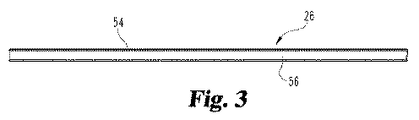
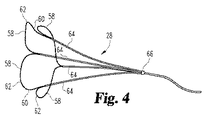
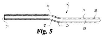
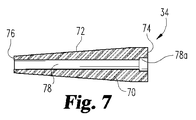
図1、図8および図9を参照して、血管内フィルタ22のための回収装置20が示される。実施の形態では血管内フィルタ22は、下大静脈(IVC)23内の位置決めにより規定されるようなIVCフィルタである。回収装置20は、外側シース24と、内側シース26と、スネア28と、ガイドワイヤカニューレ30と、超音波トランスデューサ32と、例示的な実施形態では拡張器34である先端部を含む。外側シース24の構造の詳細は、図2および2Aに示されている。内側シース26の構造の詳細は、図3および図3A示されている。スネア28の構造の詳細は、図4に示されている。ガイドワイヤカニューレ30の構造の詳細は、図5および5Aに示されている。超音波トランスデューサ32の構造の詳細は、図6および6Aに示されている。拡張器34の構造の詳細は、図7および7Aに示されている。装置20は、血管内装置であるので、その大きさ、形状、材料の選択は、静脈内に定置され移動する必要があるすべての装置およびデバイスと一致している。回収装置20およびIVCフィルタ22の相対的な向きと位置決めとの理解を補助するために(壁36によって表される)IVC23の断面が、図8および9に示される。回収装置20の手段や使用方法における重要な検討事項の一つは、所定の位置に回収装置をガイドしてIVCフィルタ22との係合とIVCフィルタ22の除去とを確保することである。スネア28は、共通の固定ベースを用いてカニューレ64を支持するする方法によって一体的に接合された複数のループ58を含む。複数のループ58を作成するワイヤはカニューレ64を介して滑り(スライド)し、カニューレごとに2つの(2)ワイヤストランドを有する。また、スネア28の一部には、スネア搬送装置29と制御ワイヤ31も含まれている。
With reference to FIGS. 1, 8 and 9, a
図1に示すように、文字Aは、ここではアプリケーション側、端または方向を表し、文字Cは、ここでは制御側、端または方向を示す。回収装置20の端部および構成部品の端部または側の向きと、動作または走行の方向の観点から、「アプリケーション側」(A)と「制御側」(C)の規則が採用され、本明細書中で使用される。これらの表現が示すように、装置20のまたは任意の部品のいずれかのアプリケーション側は、任意の治療、デバイスの配置などが発生する場所の方向またはより近くにある側または端部である。同様に、制御側は、医師が位置する場所の方向またはより近くにある装置20または任意の構成部品のいずれかの側または端部であり、制御機能またはアクションが実行される場所を表す。
As shown in FIG. 1, the letter A here represents the application side, end or direction, and the letter C here represents the control side, end or direction. From the viewpoint of the direction of the end of the collecting
「近位」および「遠位」を使用した場合、基準の異なるフレームが存在し得るので、この採択の理由の1つは、明確さを追加するためである。医療分野では、「近位」は、典型的には、心臓により近いことを意味するが、これは、患者へのカテーテルなどの装置のエントリのポイントに基づいて変更し得る。論理的には、医療分野では、「遠位」は、典型的には、心臓から遠いことを意味する。他の分野では、「近位」は、典型的には、オペレータまたはユーザに近いことを意味し、「遠位」は、典型的には、オペレータまたはユーザから遠いことを意味する。「アプリケーション側」と「制御側」の規則を採用することにより、任意の近位−遠位のあいまいさが排除されるべきである。 One of the reasons for this adoption is to add clarity because there can be different frames of reference when using “proximal” and “distal”. In the medical field, “proximal” typically means closer to the heart, but this may vary based on the point of entry of a device such as a catheter to the patient. Logically, in the medical field, “distal” typically means far from the heart. In other fields, “proximal” typically means close to the operator or user, and “distal” typically means far from the operator or user. By adopting the “application side” and “control side” rules, any proximal-distal ambiguity should be eliminated.
回収装置20は、ガイドワイヤカニューレ30を通って延びるワイヤガイド21を介して、IVC23に導入される。ワイヤガイド21は、本明細書に記載の回収(および除去)手順の間、もとの位置のままでもよいし、図9に示すように、回収装置20が一旦の適切に配置された後に除去してもよいが、ワイヤガイド21は、IVCフィルタ22が引かれており、回収装置の適切な除去のための必要がない。ワイヤガイド21は、回収装置20の初期導入に重要である。ワイヤガイド21の前進および位置決めは、既存の技術または方法の1つ(1)を用いて行われる。ワイヤガイド21に適した選択肢には、強化されたサポートを提供する固定芯線、形状記憶と操縦性と低い摩擦係数を提供する「ニチノール」ワイヤ、潤滑性コーティングを有する親水性ワイヤを含む。
The
図8を参照して、壁36によって表されるIVC23内に配置されるように、回収され除去されるべきIVCフィルタ22が示されている。図9において、IVCフィルタ22は、IVC23内の回収装置20の初期配置に関連され組み合わされて示されている。回収装置20とIVCフィルタ22との間のこの図示の関係(図9参照)は、回収(そして最終的に除去)手順の最初のステップを表す。実際には既に発生している他の準備作業があるが、本明細書で図示および説明されている回収の手順としては、参照された「最初」のステップが、IVC23内に経皮的に配置されたIVCフィルタ22に近接して適切に設計された回収装置20を位置決めし定置することである。既に発生している別の「その他」のステップは、所望の位置にIVCフィルタ22を実際に運び、IVCフィルタ22の位置決めと向きの両方が、IVCフィルタ22の構造の一部として提供される除去フックを使用して塞栓の補足と取得との両方のために適していることを確実にすることである。
Referring to FIG. 8, there is shown an
図8を続けて参照すると、IVCフィルタ22は、複数の短ストラット38と複数の長ストラット40を含むように構成され配置されている、複数のバイアスばねのワイヤ脚部またはストラット30および40を含む。短ストラット38は、「セカンダリ」と呼ばれる。長ストラット40は、「プライマリ」と呼ばれる。これらの2つの(2)複数のストラット38および40はハブ44のアプリケーション側端部42への圧着によりともに確実に固定される。反対に、ハブ44の制御側端部46は、外側に延びる除去フック48を含む。除去フック48は、ハブ44の制御側端部46を越えて制御側方向に延びる。図示されるように、IVCフィルタ22が一旦配備されると、短ストラット38および長ストラット40はすべて、IVC23の壁36に触れるべきであり、IVC23の内部に渡ってまとめて分散されるべきである。理解されるべきは、IVCフィルタ22は、開示されてクレームされる発明の一部として使用し得るフィルタの1つの形式である。説明される回収装置(および方法)は、概念的に現在市販されているものの大部分を含む各種回収フィルタを回収するために使用することができる。
With continued reference to FIG. 8, the
IVCフィルタ22を導入(すなわち定置)した搬送装置を用いてIVC23内にIVCフィルタ22が配置され、これによりストラットは、ハブ44の制御側面または端部42だったものから、配向する。除去フック48は、次いでハブ44のアプリケーション側端部46として見られたところから延びる。回収可能であると考えられているフィルタの様々な形式がたとえば頚静脈内または大腿静脈内に代替的に配置し得ることに留意すべきである。どのような配置でも、フックは、心臓に向かう。換言すると、血液はストラットからフックに向けて流れる。本開示の図1では、本明細書で規定されるように制御側方向は文字Cで示され、アプリケーション側方向は、文字Aで示されている。回収手順については、回収装置20のエントリポイントは、搬送方向と反対である。しかし、制御側とアプリケーション側の参照は、規定されるように実質的に同じままである。ハブ44内にともに圧着されるかいくつかの他の方法または構造によるかどうかによらず、除去フック48とストラット38および40とが確実に接続することが重要である。IVCフィルタ22の回収と除去の際には、フック48は、回収装置20のループによって初期の係合のために使用されるだろう。フック48を引くことは、除去手順の一部であり、ハブに力を及ぼして順にストラット38および40に力を及ぼし、ハブからフックまたはストラットからハブのいずれかで分離しようとする傾向にある。一体に連結し、確実に接合した状態にあることは、回収および除去手順の一部として重要である。
The
図2および図2Aに示すように、外側シース24は環状であり、可撓性スリーブが中空内部あるいは管腔52を規定する管状壁50に構成され配置される。本明細書に記載されるように意図された使用のために、好ましくは外側シース24の長さは約65センチメートルある。例示的な実施形態のゲージは、「Fr」スケールを使用して約8.5Frであり、または約2.83ミリメートルの外径である。7.0Frサイズ以下のように、より小さなシース径が許容されるであろうことが企図される。外側シース24の機能と用途を考慮すると、外側シース24に適した材料は、ポリエチレンおよび他の半可撓性プラスチックを含む。これらの材料は、または、一般的に円筒形の管またはスリーブの所望の開始形状に容易に形成されるか押し出すことができる、耐久性があるが可撓性の生体適合性材料を表す。外壁50の厚さは、材料選択に部分的に依存するが、0.008−0.020インチの範囲である。論理的には、耐久性が低く硬い材料ほど、僅かに厚い壁を必要とするであろう。
As shown in FIGS. 2 and 2A, the
外側シース24は、半径方向に最も外側の部品を表しているので、その内部寸法は、ワイヤガイドカニューレ30のアプリケーション側端部51および拡張器34を除く他の部品を収容するために選択される。同時に、シース24の外側管状壁の最大サイズは、IVC23内に配置し移動するために制限され制御されなければならない。外側シース24内にIVCフィルタ22の定置場所への経皮的進入を介して患者の外部に拡張するために十分な長さを有してもよい。このような実施形態では、たとえば、外側シース24の制御側部または端部、および/またはそれに取り付けられた操作部は身体の外側にあり、一方アプリケーション側部は、IVCフィルタ22に隣接し初期的にIVUSトランスデューサ32の制御側端部に延びている。好ましくは、外側シース24は、一体性を維持しながら血管を通って移動できるように、血管内カテーテルに用いられる材料といった、半可撓性プラスチックまたは他の材料である。現在利用可能なシースは、血管系におけるシースの配置によって当然に示唆されるように、中に収まるような折りたたまれたフィルタまたはスネアのような他の部品を許可するが、直径が小さくなるように寸法決めされている。
Since the
内側シース26は、図3および図3Aに示すように、環状であり、中空の内管腔56を規定する管状壁54を用いて構成され配置された可撓性スリーブ26である。本明細書に開示されるような意図の使用のために、好ましくは、内側シース26の長さは約75センチメートルあり、外径は約1.2ミリメートルである。内側シース26の機能と用途とを考慮すると、内側シース26に適した材料は、ポリエチレンおよび他の半可撓性プラスチックを含む。これらの材料は、それぞれほぼ円筒形の管またはスリーブの所望の開始形状に容易に形成されるかまたは押し出すことができる、耐久性があるが可撓性の生体適合性材料を表す。外壁54の厚さは、材料選択に部分的に依存するが、0.004〜0.012インチの範囲である。論理的には、耐久性の低い硬い材料ほど、僅かに厚い壁を必要とするであろう。
The
IVUSに適合するスネア28は、図4を参照し、4つの相互接続された断面に構成され配置されており、それらの各々は、本明細書でループ58として識別される。これらの4つの相互接続されたループ58は、それぞれテーパ状の端部60および幅広の外端62を有する形状とされる。各ループ58のほぼ涙型の形状はその全体形状を通して実質的に平坦ではない。代わりに、各ループ58の外端62(すなわち大きい方の端)は、図示されているように、半径方向外側の屈曲部を含む。この屈曲部は、ほぼ共通の幾何学的な面内、すなわち同一平面上の、各外端62、少なくとも各外端62の一部に配置する。この同一平面上の配置は、IVCフィルタ22の除去フック48を係合するための4つの(4)ループ58の各々の外端62を位置決めするのに役立つ。
A
スネア28は、好ましくはポリイミドまたは代わりにステンレス鋼から構成され、ワイヤループ58の配備および構造的支持を補助するための4つの(4)カニューレ64が使用される。各カニューレ64は、隣接するカニューレとの間に延び各ループ58を形成するNiTiの2つ(2)の断面が含まれる。カニューレの断面は、共通のベースまたはハブ66でともにはんだ付けされる。ループ58は、除去フック48の周囲および上へとスネア28を閉じるために引き戻される(すなわち、対応するカニューレを通してスライドする)ことが可能である。IVUSの監視およびガイダンスの下で、スネア28の位置は、4つの(4)カニューレ64の位置を見ることによって決定することができる。
The
ガイドワイヤカニューレ30は、図5および図5Aを参照して、中空内部79を規定する側壁77を有する環状の管状形状に構成され、配置されている。中空内部79の大きさは0.035−0.040インチのサイズの範囲内のワイヤガイドを受けて収容する。ガイドワイヤカニューレ30は、ほぼ管状の形状を有するものとして説明されているが、ガイドワイヤカニューレ30は、好ましくは、実質的に均一な側壁の厚さを有するほぼ円筒形の形状を有するであろう。このように、図5Aを参照し、カニューレ30の全体は、好ましくは、横断面でほぼ円形の形状を有し、中空内部79は、好ましくは横断面でほぼ円形の形状を持つだろう。ガイドワイヤカニューレ30は、アプリケーション側端部または先端51と、制御側部53と、2つ(2)の離間した屈曲部55および57と、を含み、屈曲部55および57はその間に傾斜部59を規定する。アプリケーション側端部51は拡張器34に位置し、IVUSトランスデューサ32を通るか通過して延びる。制御側部53は、回収装置20の内部を通って延びる部分を表す。2つ(2)の屈曲部55および57は、オフセット傾斜部59作成する。傾斜部59は、図9に示された初期位置においてスネア28のループ58に隣接して配置される。この傾斜部59は、エッジ位置から実質的に軸上の中心位置への位置合わせのシフトを生む。
The
図6および6Aを参照すると、超音波トランスデューサ32は、IVCフィルタ22およびその定置と、スネア28の配備と、除去フック48とスネア28の一部を係合することによるIVCフィルタ22の回収と、を可視化する際に使用するために構成され配置される。超音波トランスデューサ32の血管内配置および使用を考慮し、IVUSという略語が適用され、トランスデューサ32、すなわちIVUSトランスデューサ32の省略形として本明細書中で使用される。この略語はまた、IVCフィルタ22の回収および除去をガイドし監視する方法を説明するために参照され使用される。IVUSトランスデューサ32は、本体65およびそのほぼ円筒形の外壁67によって規定されるほぼ円筒形の形状を有している。位置決めおよび位置合わせのために含まれているのは、アプリケーション側同軸ハブ32aと制御側同軸ハブ32bである。ハブ32aは、拡張器34の制御側端部74のカウンタボア内に収まる。
With reference to FIGS. 6 and 6A, the
代表的な実施形態では、IVUSトランスデューサ32は、セラミックスリーブ63によって包まれたステンレス製の筒状コア61を含む。セラミックスリーブ63の周りを包むのは、フレキシブルなプリント回路基板である。IVUSトランスデューサの「構造」は、複数の素子から構成されるアレイを含む。上記のアレイ型トランスデューサは、シーケンシャルに個々のアレイ素子を励起しスキャンを実行し、可動部分を有さない。代替の実施形態では、固定トランスデューサを備えたモータ駆動回転トランスデューサまたはモータ駆動鏡などがある。サイズの考慮事項により、モータは患者の外部であり、回転ケーブルによっていずれかの素子またはミラーに接続する。代替的に、モータは、マイクロサイズであり、カテーテルのアプリケーション端部に組み込むことができる。中心ボア69は、ガイドワイヤカニューレ30の一部を通して受け入れるように構成され配置されている。制御側端部のIVUSトランスデューサ32は管腔52のアプリケーション側端内で初期的に受けられる。
In the exemplary embodiment, the
図1、図6、図6A、図9の例示的な実施形態によって表される構成は、ガイドワイヤカニューレ30と、ガイドワイヤ21と、IVUSトランスデューサ32と、拡張器34(すなわち回収装置20の先端)との間の具体的な配置および関係を提供する。代替の実施形態は、図14−16に示され、これらの各々は、以下により詳細に説明される。加えて、IVUSトランスデューサの選択、形式、構成、および動作は、例示的な実施形態のために開示されているものから変えることができることに留意されたい。1つ(1)の変形例が、図14−16に開示されているがさらに、3Dスキャン機能が選択されたIVUSトランスデューサに統合され得ることが企図される。3Dスキャン機能は、2つ(2)の異なる機械的軸においてモータ駆動するように構成され配置された単一素子のトランスデューサを含んでもよい。この3Dスキャン機能を提供するための別のオプションは、直線アレイトランスデューサを使用して、回転運動とそれを駆動することである。3Dスキャン機能を提供するための別のオプションは、十分な2次元の線形アレイを使用することである。このオプションでは行−列アドレススキームは、異なる伝達イベントの別の素子にアクセスするために使用される。
The configuration represented by the exemplary embodiment of FIGS. 1, 6, 6A, and 9 includes a
拡張器34は、図7および図7A参照すると、制御側端部74からアプリケーション側端部76に収束するテーパ側壁72を有するほぼ円錐台の本体70を有して構成され、配置されている。本体70は、ガイドワイヤカニューレ30のアプリケーション側端部51を受ける同軸中心ボア78によって規定される。カウンタボア78aは、ボア78と同軸であり、IVUSトランスデューサ32のアプリケーション側ハブ32aを受け入れるような大きさと形状である。ガイドワイヤカニューレ30はワイヤガイド21と協働して使用され、IVCフィルタ22の回収のために回収装置20を位置決めするのを補助し、患者からIVCフィルタ22を除去するのを補助するために使用される。ワイヤガイド21は、除去ステップのために必要とされない。適切にこれらの統合された機能を実行するために、ガイドワイヤカニューレ30のアプリケーション側端部51が確実に中央ボア78内に固定される。この確実な関係は、好ましくは、カウンタボア78とアプリケーション側端部51の適合するサイズおよび形状を含む。拡張器34は、回収装置20のアプリケーション側端部に位置し、ガイドワイヤカニューレ30のアプリケーション側端部を受ける。
7 and 7A, the
図9−13を参照し、引き続き図1と8とを参照すると、これらの図は、定置されたIVCフィルタ22および患者からのそのIVCフィルタ22の除去における回収ステップまたは段階に関連する構造的構成を示す。回収方法の最初のステップは、静脈への回収装置20のエントリに続き、IVCフィルタ22の場所に対する回収装置20の適切な位置決めを確立することである。図9に、回収装置20の適切な初期位置合わせが示される。回収手順または方法のこの最初のステップの重要な側面は、IVCフィルタ22の除去フック48の位置とIVUSトランスデューサ32の撮像面84とが一致するように、回収装置20を配置することであるこの幾何学的な一致面は破線84で示されている。理解されるように、描画された図面は概略であり、必ずしも一定の縮尺で描かれていない。図示のように、スネア28の初期的に引き抜かれる折りたたまれたループ58は、外側シース24によって捕捉される。ループ58のばねバイアスの性質および部分的にループに使用されるワイヤは、この補足を可能にする。これらの特性は、補足する外側シースが引き戻されるときにスネア28が開くことを可能にして、ワイヤは、全体的な方法の次のステップの一部である操作である、ループ58を開くために延ばされる。
With reference to FIGS. 9-13, and continuing reference to FIGS. 1 and 8, these figures illustrate the structural configuration associated with the deployed
IVCフィルタ22の回収および静脈から最終的に除去する方法の次のステップは、図10に示されている。このステップでは、外側シース24は、制御側の方向に僅かに引き戻される。この動作は、開口部92を作成する。拘束された外側シース24の除去はスネア28のループ58がその捕捉され、折りたたまれた状態から開かれることを可能とする。ループ58を備えるワイヤは、カニューレ64によって捕捉され、そこを通してスライドすることができる。閉じられたループが、開口部92を通ってアプリケーション側方向に向かって外側に拡張または移動する際に、開いて拡大することを可能とする。そして、このステップが実行された後、「IVUS適合する」スネア28は、アプリケーション側方向に前進され、除去フック48と整列される。この意図はスネア28のループ58の1つをIVCフィルタ22の除去フック48上へ「フックする(ひっかける)」ことができるように、または固定することができるようにすることである。スネア28のループ58の1つがフック48と係合する確率を向上させるための1つの技術は、各ループ58の上端62が同様に屈曲されすべての屈曲部62がほぼ互いに同一平面上にあるように、ほぼ平面状の構成に各ループ58の外端62を屈曲させることである。各ループ58の外端62のこれらの屈曲部を含む幾何学的な面は、除去フック48の湾曲部を含む幾何学的な面とほぼ一致する。IVUSトランスデューサ32を用いて画像化することにより、配置を確認することができる。
The next step in the method of collecting and finally removing the
ループ58および除去フック48との間に適切な関係があることがIVUS画像の可視化から表示された場合は、回収の方法は継続する。回収(および除去)方法における次のステップは、アプリケーション側方向に内側シース26を進めることである。このステップは、図11に示されている。内側シース26はスネア28とは独立して、また外側シース24とは独立して移動させることが可能である。個々ループ58のテーパ設計およびハブのアプリケーション側面への共通の接続は、アプリケーション側、内側シースの開放端部を、ハブ上および接合ループ58の開始部分(すなわちベース)上を容易にスライド可能とする。一旦ハブおよび個々のループの端部が内側シース26の開放端内に受けられると、内側シース26は容易に、図11に示した位置に前進することができる。折りたたまれている各ループの大きさを減らすように、ループ58を含むワイヤは、同時に幾分か引き抜くことができる。
If the proper relationship between the
前進する内側シース26がループ58を閉じてかたく入れ子にし、そうすることで、除去フック48の周りでループ58が確実に閉じられる。IVUSトランスデューサ32は、方法の一部のステップとしてこれらの構成部品の動きを画像化するために使用される。IVUSトランスデューサ32は、スネア28が適切にIVCフィルタ22の回収および除去のために除去フック48に係合することを確実にするために、ループ58および除去フック48との間の関係を監視するために使用される。
The advancing
記載される方法の次のステップは、図12に示すように、アプリケーション側方向に約5.5センチメートル回収装置20を進めることである。この距離は、シースマーカー(図示せず)を用いて測定される。次のステップでは、図13に示すように外側シース24は、アプリケーション側方向に前進される。外側シース24のこの作用は、外向きに延びるストラット38と40とを係合させ、内側に折りたたまれるようにさせる。ストラット38および40の外側シース24への作用によって加えられる力は、静脈の壁からストラットの分離を開始する。前進を継続すると、図13を参照して、IVCフィルタ22は、回収装置20内に捕捉される。外側シース24が一旦IVUSトランデューサ32上の終了位置に前進されると、回収装置20は、今度は補足されたIVCフィルタ22を用いて患者の静脈から除去される準備が整う。
The next step in the described method is to advance the approximately 5.5
IVUSトランスデューサ32の使用は、超音波ガイド下でIVCフィルタ22を回収することを可能とし、従来技術の代表としての経皮的回収セットとX線透視スイートの使用を向上させることができる。回収スネア28は、容易に視認できIVUSのガイダンスの下に配置することができるように構成され、配置されている。回収装置20は、拡張器34の制御側端部に隣接する装置20に組み込まれたIVUSトランスデューサ32を含むように構成され配置されている。ガイドワイヤカニューレ30は、IVUSトランスデューサ32を通って延び、ガイドワイヤカニューレ30の端部は、拡張器34の内に受けられる。この構成は、カテーテルの交換を必要とすることなく、単一のアクセスポイントを介して実行されるIVCフィルタ22の回収および除去方法を可能にする。回収装置は、IVCフィルタ22の回収中のIVUSトランスデューサ32の撮像面における重要なスネア28およびIVCフィルタ22の機能を維持するために構成され、配置されている。
The use of the
回収装置20は、IVCフィルタ22の回収を超音波ガイド下で簡単に行うことを可能にする。この態様を容易にするために、スネア28はその位置決めが超音波誘導下で容易に確認できるように構成され、配置されている。開示された方法の回収ステップ中のIVCフィルタ22の位置とスネア28の場所といった関連する情報がその撮像面にキャプチャされるように、IVUSトランスデューサが配置されている。述べたように、これのすべては、カテーテルの交換を必要とすることなく、単一のアクセスサイトを介して達成される。
The
図14〜16を参照して、回収装置のアプリケーション側端部のための3つの(3)他の実施形態が示される。最初に図14を参照して、埋め込まれたIVUSトランスデューサ102を含むIVUSフィルタ回収装置100が開示される。この実施形態は、IVUSトランスデューサ102と「迅速交換」ワイヤガイド104と先端106との設計オプションを提供する。この実施形態は、IVUSトランスデューサ102の特定の構成に依存しない。
With reference to FIGS. 14-16, three (3) other embodiments for the application end of the collection device are shown. Referring initially to FIG. 14, an IVUS
任意には、IVUSトランスデューサは、中空であってもよいし、中空でなくてもないが、後者がIVUSトランスデューサ102として開示される。このため、利用可能であり、回収装置100の図示された構造と互換性があるような代替案は、1つの(1)オプションとして、トルクケーブル駆動トランスデューサの使用を含む。その他のオプションは、様々な構成のオンサイトのモータ回転トランスデューサ、アレイトランスデューサ、3Dトランスデューサの使用を含む。
Optionally, the IVUS transducer may or may not be hollow, but the latter is disclosed as
回収装置は、スネア28と機械的支持108とを含み、機械的支持108は、先端106およびトランスデューサ102が配置されるカテーテル110のアプリケーション側または端部と、スネア28およびカテーテル110の本体とが配置される制御側または端部との間の接続を提供する。
The retrieval device includes a
図14の例示的な実施形態では、機械的支持108は中空であり、ワイヤガイド、トランスデューサケーブル、トルクケーブル、流体管腔、などを受けることができるように構成され、配置されている。代替的に、機械的な支持は、固体部材であってもよい。文字Aで示されるアプリケーション側または端部は、トランスデューサ102の1つの(1)端に隣接する先端106を含む。
In the exemplary embodiment of FIG. 14, the
図14、15および16に示すように、いくつかの設計オプションが、トランスデューサの先端106に利用できる。図14に関連する1つの(1)のオプションは、迅速交換管腔112を用いてトランスデューサの先端部106を構成することである。図15に関連する別のオプションは、ワイヤガイド114の1つの(1)端部がトランスデューサの先端116のアプリケーション側または端部の受開口部118に永久的に埋め込まれるように、ワイヤガイド114とトランスデューサの先端116とを構成することである。図16に関連する別のオプションは、ワイヤガイド(104、114)を除去し、代わりに先端120のアプリケーション側または端部を実質的に半球形状に丸くして形成することである。先端または面におけるこの実質的な半球形状は、対応する回収装置が所望の位置に移動される際に血管の穿刺または引き裂きのリスクを低減する。
Several design options are available for the
本発明は、図面および前述の説明において詳細に図示および説明してきたが、同じことが例示的であり文字において限定的ではないと考えられるべきであり、好ましい実施形態のみが示され説明され、以下の特許請求の範囲によって定義される本発明の精神内にあるすべて変更、均等物、および修正が保護されることが望まれると理解される。本明細書で引用したすべての刊行物、特許、および特許出願は、各個々の刊行物、特許、または特許出願が具体的かつ個々に参照により組み込まれその全体が本明細書に記載されると示されるように、参照により本明細書に組み込まれる。 While the invention has been illustrated and described in detail in the drawings and foregoing description, the same is to be considered as illustrative and not restrictive in character; only the preferred embodiments are shown and described; It is understood that all changes, equivalents, and modifications that are within the spirit of the invention as defined by the following claims are desired to be protected. All publications, patents, and patent applications cited herein are intended to be incorporated herein by reference, specifically and individually, as if each individual publication, patent, or patent application was specifically and individually incorporated by reference. As indicated, it is incorporated herein by reference.
Claims (28)
外管腔を規定する環状壁を有する外側シースと、
内管腔を規定する環状壁を有する内側シースとを備え、前記内側シースは、前記外管腔内に位置するとともに、前記身体の血管から前記血管内フィルタを除去する際に使用するために構成および配置され、
前記内管腔内に位置する回収部材を備え、前記回収部材は複数のループを有するスネアを含み、
前記回収部材のアプリケーション側に位置する超音波トランスデューサを備え、前記内側シースは前記超音波トランスデューサから独立して移動するように構成され、
前記外側シースと前記内側シースとの間に延びるガイドワイヤカニューレと、
前記回収部材のアプリケーション側に位置する拡張器とを備え、前記拡張器は、前記超音波トランスデューサに結合され、前記ガイドワイヤカニューレを受け、
前記複数のループは、前記血管内フィルタと位置合わせさせて前記内側シースを前記複数のループに向けて延ばすと前記スネアが前記血管内フィルタの一部に向かって閉じるようにするために、使用される、回収装置。 A collection device for removing an intravascular filter from a blood vessel of a patient's body, the collection device comprising:
An outer sheath having an annular wall defining an outer lumen;
An inner sheath having an annular wall defining an inner lumen, wherein the inner sheath is located in the outer lumen and configured for use in removing the intravascular filter from the blood vessel of the body And placed
A recovery member located within the inner lumen, the recovery member including a snare having a plurality of loops ;
Comprising an ultrasonic transducer located on the application side of the retrieval member , wherein the inner sheath is configured to move independently of the ultrasonic transducer ;
A guide wire cannula extending between the outer sheath and the inner sheath;
E Bei a dilator located on the application side of the collecting member, said dilator coupled to said ultrasonic transducer, receiving the guide wire cannula,
The plurality of loops are used to align with the intravascular filter and cause the snare to close toward a portion of the intravascular filter when the inner sheath extends toward the plurality of loops. that, collecting device.
外管腔を規定する環状壁を有する外側シースと、
内管腔を規定する環状壁を有する内側シースとを備え、前記内側シースは、前記外管腔内に位置するとともに、前記IVCから前記IVCフィルタを除去する際に使用するために構成および配置され、
前記内管腔内に位置する回収部材を備え、前記回収部材は複数のループを有するスネアを含み、
前記回収部材のアプリケーション側に位置する血管内超音波(IVUS)トランスデューサを備え、前記内側シースは前記IVUSトランスデューサから独立して移動するように構成され、
前記外側シースと前記内側シースとの間に延びるガイドワイヤカニューレを備え、前記ガイドワイヤカニューレは、アプリケーション側端部を含み、
前記回収装置のアプリケーション側端部に位置する拡張器を備え、前記拡張器は、前記IVUSトランスデューサに結合され、前記ガイドワイヤカニューレのアプリケーション側端部を受け、
前記複数のループは、前記IVCフィルタと位置合わせさせて前記内側シースを前記複数のループに向けて延ばすと前記スネアが前記IVCフィルタの一部に向かって閉じるようにするために、使用される、回収装置。 A recovery device for recovering an IVC filter from a patient's inferior vena cava (IVC) , the recovery device comprising:
An outer sheath having an annular wall defining an outer lumen;
An inner sheath having an annular wall defining an inner lumen, the inner sheath being located in the outer lumen and configured and arranged for use in removing the IVC filter from the IVC ,
A recovery member located within the inner lumen, the recovery member including a snare having a plurality of loops ;
An intravascular ultrasound ( IVUS ) transducer located on the application side of the retrieval member , wherein the inner sheath is configured to move independently of the IVUS transducer ;
E Bei guidewire cannula extending between said inner sheath and the outer sheath, the guide wire cannula comprises an application-side end,
E Bei dilator positioned on the application side end portion of the recovery device, the dilator is coupled to the IVUS transducer receives the application end of the guide wire cannula,
The plurality of loops are used to align with the IVC filter and cause the snare to close toward a portion of the IVC filter when the inner sheath extends toward the plurality of loops . Recovery device.
前記回収装置を提供するステップと、
患者の身体の血管内に前記回収装置を挿入するステップと、
前記撮像面が前記患者内の選択した場所と一致するように前記回収装置を位置決めするステップと、
前記回収部材を前記超音波トランスデューサから独立して前記撮像面に向けて移動させるように前記回収装置を操作するステップと、
前記外側シースを後退させて前記複数のループが外側に開いて展開するための開口部を形成することにより、前記スネアの一部を前記撮像面の中に位置決めするステップと、
前記複数のループを前記血管内フィルタと位置合わせするステップと、
前記内側シースを前記複数のループに向けて延ばすことにより、前記血管内フィルタの一部の上で前記スネアを閉じるステップと、
前記内側シースおよび前記スネアを前記血管内フィルタとともに前記外側シースの中に後退させるステップと、
前記血管内フィルタとともに前記回収装置を引き出すステップと、を含む方法。 A patient (excluding humans) using a retrieval device comprising a retrieval member comprising a snare having an outer sheath, an inner sheath, a plurality of loops and a delivery device, an ultrasonic transducer, a guide wire cannula, and a dilator ) In which the ultrasonic transducer has an imaging surface, the method comprising:
Providing the recovery device;
Inserting the retrieval device into a blood vessel of a patient's body;
Positioning the retrieval device such that the imaging surface coincides with a selected location within the patient;
Operating the recovery device to move the recovery member toward the imaging surface independently of the ultrasonic transducer;
Positioning the portion of the snare within the imaging surface by retracting the outer sheath to form an opening for the plurality of loops to open outward and deploy;
Aligning the plurality of loops with the intravascular filter;
Closing the snare over a portion of the intravascular filter by extending the inner sheath toward the plurality of loops;
Retracting the inner sheath and the snare into the outer sheath with the intravascular filter;
Withdrawing the collection device with the intravascular filter.
外管腔を規定する環状壁を有する外側シースと、
内管腔を規定する環状壁を有する内側シースとを備え、前記内側シースは、前記外管腔内に位置するとともに、前記身体の血管から前記血管内フィルタを除去する際に使用するために構成および配置され、
前記内管腔内に位置する回収部材を備え、前記回収部材は複数のループを有するスネアを含み、
前記回収部材のアプリケーション側に位置する超音波トランスデューサを備え、前記内側シースは前記超音波トランスデューサから独立して移動するように構成され、
前記外側シースと前記内側シースとの間に延びるガイドワイヤカニューレを備え、前記超音波トランスデューサは前記ガイドワイヤカニューレを受け、
前記複数のループは、前記血管内フィルタと位置合わせさせて前記内側シースを前記複数のループに向けて延ばすと前記スネアが前記血管内フィルタの一部に向かって閉じるようにするために、使用される、回収装置。 A collection device for removing an intravascular filter from a blood vessel of a patient's body, the collection device comprising:
An outer sheath having an annular wall defining an outer lumen;
An inner sheath having an annular wall defining an inner lumen, wherein the inner sheath is located in the outer lumen and configured for use in removing the intravascular filter from the blood vessel of the body And placed
A recovery member located within the inner lumen, the recovery member including a snare having a plurality of loops;
Comprising an ultrasonic transducer located on the application side of the retrieval member, wherein the inner sheath is configured to move independently of the ultrasonic transducer;
A guidewire cannula extending between the outer sheath and the inner sheath, the ultrasonic transducer receiving the guidewire cannula;
The plurality of loops are used to align with the intravascular filter and cause the snare to close toward a portion of the intravascular filter when the inner sheath extends toward the plurality of loops. that, collecting device.
外管腔を規定する環状壁を有する外側シースと、An outer sheath having an annular wall defining an outer lumen;
内管腔を規定する環状壁を有する内側シースとを備え、前記内側シースは、前記外管腔内に位置するとともに、前記IVCから前記IVCフィルタを除去する際に使用するために構成および配置され、An inner sheath having an annular wall defining an inner lumen, the inner sheath being located in the outer lumen and configured and arranged for use in removing the IVC filter from the IVC ,
前記内管腔内に位置する回収部材を備え、前記回収部材は複数のループを有するスネアを含み、A recovery member located within the inner lumen, the recovery member including a snare having a plurality of loops;
前記回収部材のアプリケーション側に位置する血管内超音波(IVUS)トランスデューサを備え、前記内側シースは前記IVUSトランスデューサから独立して移動するように構成され、Comprising an intravascular ultrasound (IVUS) transducer located on the application side of the retrieval member, wherein the inner sheath is configured to move independently of the IVUS transducer;
前記外側シースと前記内側シースとの間に延びるガイドワイヤカニューレを備え、前記ガイドワイヤカニューレは、アプリケーション側端部を含み、前記IVUSトランスデューサを受け、A guidewire cannula extending between the outer sheath and the inner sheath, the guidewire cannula including an application end and receiving the IVUS transducer;
前記複数のループは、前記IVCフィルタと位置合わせさせて前記内側シースを前記複数のループに向けて延ばすと前記スネアが前記IVCフィルタの一部に向かって閉じるようにするために、使用される、回収装置。The plurality of loops are used to align with the IVC filter and cause the snare to close toward a portion of the IVC filter when the inner sheath extends toward the plurality of loops. Recovery device.
Applications Claiming Priority (3)
| Application Number | Priority Date | Filing Date | Title |
|---|---|---|---|
| US201261739088P | 2012-12-19 | 2012-12-19 | |
| US61/739,088 | 2012-12-19 | ||
| PCT/US2013/071254 WO2014099244A1 (en) | 2012-12-19 | 2013-11-21 | Apparatus and method for the retrieval of an intravascular filter |
Publications (3)
| Publication Number | Publication Date |
|---|---|
| JP2016505323A JP2016505323A (en) | 2016-02-25 |
| JP2016505323A5 JP2016505323A5 (en) | 2016-09-01 |
| JP6282283B2 true JP6282283B2 (en) | 2018-02-21 |
Family
ID=50931783
Family Applications (1)
| Application Number | Title | Priority Date | Filing Date |
|---|---|---|---|
| JP2015549405A Active JP6282283B2 (en) | 2012-12-19 | 2013-11-21 | Device and method for collecting intravascular filter |
Country Status (6)
| Country | Link |
|---|---|
| US (1) | US9655647B2 (en) |
| EP (1) | EP2934650B1 (en) |
| JP (1) | JP6282283B2 (en) |
| CN (1) | CN104955514B (en) |
| AU (1) | AU2013363667B2 (en) |
| WO (1) | WO2014099244A1 (en) |
Families Citing this family (15)
| Publication number | Priority date | Publication date | Assignee | Title |
|---|---|---|---|---|
| JP6523964B2 (en) * | 2012-12-19 | 2019-06-05 | マフィン・インコーポレイテッドMuffin Incorporated | Device and method for delivery of intravascular filters |
| EP3007648B1 (en) | 2013-06-14 | 2019-11-13 | Avantec Vascular Corporation | Inferior vena cava filter and retrieval systems |
| CN112220585B (en) | 2014-12-12 | 2024-03-08 | 阿万泰血管公司 | Inferior vena cava filter retrieval system with interposed support member |
| US10092324B2 (en) | 2015-09-04 | 2018-10-09 | The Trustees Of The University Of Pennsylvania | Systems and methods for percutaneous removal of objects from an internal body space |
| EP3386434A4 (en) * | 2015-12-10 | 2019-05-29 | Avantec Vascular Corporation | Ivc filter retrieval system sheath improvements |
| EP4180004A1 (en) * | 2015-12-31 | 2023-05-17 | Lifetech Scientific (Shenzhen) Co., Ltd | Catcher |
| CN107684452B (en) * | 2016-08-04 | 2021-05-07 | 先健科技(深圳)有限公司 | Catching device |
| KR102294436B1 (en) * | 2016-05-03 | 2021-08-25 | 아디언트 메디컬, 인코포레이티드 | Method and apparatus for placing and retrieving an object from a cavity |
| US10729415B2 (en) * | 2016-05-20 | 2020-08-04 | Cook Medical Technologies Llc | Vibrating medical device assembly and method of retrieving embedded implantable device |
| US10874499B2 (en) | 2016-12-22 | 2020-12-29 | Avantec Vascular Corporation | Systems, devices, and methods for retrieval systems having a tether |
| US20190133742A1 (en) * | 2017-11-07 | 2019-05-09 | Mohammad Reza Rajebi | Ivc filter retrieval kit |
| EP3764927A4 (en) * | 2018-03-15 | 2021-11-17 | C. R. Bard, Inc. | Anatomical extraction device |
| CN112584799A (en) | 2018-06-29 | 2021-03-30 | 阿万泰血管公司 | Systems and methods for implants and deployment devices |
| CN109498074A (en) * | 2019-01-04 | 2019-03-22 | 上海形状记忆合金材料有限公司 | Method Wholly-degradable plugging device dedicated driving means and its connect with plugging device |
| CN110507447A (en) * | 2019-09-24 | 2019-11-29 | 浙江归创医疗器械有限公司 | Vena cava filter and its recyclable device |
Family Cites Families (38)
| Publication number | Priority date | Publication date | Assignee | Title |
|---|---|---|---|---|
| US3672367A (en) | 1970-05-25 | 1972-06-27 | Abbott Lab | Retaining clip for catheter sheath |
| US4525157A (en) | 1983-07-28 | 1985-06-25 | Manresa, Inc. | Closed system catheter with guide wire |
| US5415630A (en) | 1991-07-17 | 1995-05-16 | Gory; Pierre | Method for removably implanting a blood filter in a vein of the human body |
| US5325860A (en) * | 1991-11-08 | 1994-07-05 | Mayo Foundation For Medical Education And Research | Ultrasonic and interventional catheter and method |
| US5545151A (en) * | 1994-11-22 | 1996-08-13 | Schneider (Usa) Inc | Catheter having hydrophobic properties |
| US6530952B2 (en) * | 1997-12-29 | 2003-03-11 | The Cleveland Clinic Foundation | Bioprosthetic cardiovascular valve system |
| US6530902B1 (en) | 1998-01-23 | 2003-03-11 | Medtronic, Inc. | Cannula placement system |
| US6342062B1 (en) * | 1998-09-24 | 2002-01-29 | Scimed Life Systems, Inc. | Retrieval devices for vena cava filter |
| US6440077B1 (en) | 1999-06-02 | 2002-08-27 | Matthew T. Jung | Apparatus and method for the intravascular ultrasound-guided placement of a vena cava filter |
| US6645152B1 (en) * | 1999-06-02 | 2003-11-11 | Matthew T. Jung | Apparatus for the intravascular ultrasound-guided placement of a vena cava filter |
| US6306097B1 (en) * | 1999-06-17 | 2001-10-23 | Acuson Corporation | Ultrasound imaging catheter guiding assembly with catheter working port |
| US6554801B1 (en) * | 2000-10-26 | 2003-04-29 | Advanced Cardiovascular Systems, Inc. | Directional needle injection drug delivery device and method of use |
| AU2002220027A1 (en) * | 2000-11-03 | 2002-05-15 | Cook Incorporated | Medical grasping device |
| US6458145B1 (en) * | 2000-11-28 | 2002-10-01 | Hatch Medical L.L.C. | Intra vascular snare and method of forming the same |
| US20030125751A1 (en) * | 2001-06-27 | 2003-07-03 | Patrick Griffin | Catheter |
| US7717865B2 (en) | 2003-09-30 | 2010-05-18 | Boston Scientific Scimed, Inc. | Side loading wire torquing device |
| US7591813B2 (en) | 2003-10-01 | 2009-09-22 | Micrus Endovascular Corporation | Long nose manipulatable catheter |
| CA2562688A1 (en) | 2004-04-16 | 2005-11-03 | Cook, Inc. | Removable vena cava filter for reduced trauma in collapsed configuration |
| US7625390B2 (en) | 2004-04-16 | 2009-12-01 | Cook Incorporated | Removable vena cava filter |
| US7803171B1 (en) | 2004-06-14 | 2010-09-28 | Uflacker Renan P | Retrievable inferior vena cava filter |
| AU2005286894A1 (en) | 2004-09-20 | 2006-03-30 | Cook, Inc. | Anti-thrombus filter having enhanced identifying features |
| JP4977831B2 (en) * | 2004-11-08 | 2012-07-18 | クック メディカル テクノロジーズ エルエルシー | Clot filter made for wire guide |
| US7993362B2 (en) * | 2005-02-16 | 2011-08-09 | Boston Scientific Scimed, Inc. | Filter with positioning and retrieval devices and methods |
| CA2633855A1 (en) * | 2005-12-30 | 2007-07-12 | C.R. Bard Inc. | Embolus blood clot filter delivery system |
| CA2633866A1 (en) * | 2005-12-30 | 2007-07-12 | C.R. Bard Inc. | Embolus blood clot filter removal system and method |
| WO2007109257A2 (en) * | 2006-03-20 | 2007-09-27 | William A. Cook Australia Pty. Ltd. | Medical grasping device |
| US7988674B2 (en) | 2006-10-30 | 2011-08-02 | Medtronic, Inc. | Externally releasable body portal anchors and systems |
| US20080119867A1 (en) | 2006-10-31 | 2008-05-22 | Cook Incorporated | Puncture and abrasion resistant sheath |
| US8043324B2 (en) | 2007-10-30 | 2011-10-25 | Boston Scientific Scimed, Inc. | Intravascular filter device with piezoelectric transducer |
| US20090118760A1 (en) | 2007-11-07 | 2009-05-07 | William Cook Europe Aps | Vascular filter retrieval device |
| US20090248142A1 (en) * | 2008-03-25 | 2009-10-01 | Medtronic Vascular, Inc. | Methods, Devices and Systems for Treating Venous Insufficiency |
| US9962523B2 (en) | 2008-06-27 | 2018-05-08 | Merit Medical Systems, Inc. | Catheter with radiopaque marker |
| WO2010091212A1 (en) | 2009-02-04 | 2010-08-12 | Blatter Duane D | Blood filter retrieval devices and methods |
| FR2945206B1 (en) | 2009-05-06 | 2011-06-17 | Aln | EXTRACTION KIT FOR FILTER FOR CELLAR VEIN |
| US9504589B2 (en) * | 2009-10-29 | 2016-11-29 | Cook Medical Technologies Llc | Stent delivery system with nitinol trigger wire |
| WO2012003369A2 (en) | 2010-06-30 | 2012-01-05 | Muffin Incorporated | Percutaneous, ultrasound-guided introduction of medical devices |
| US20120022578A1 (en) | 2010-07-20 | 2012-01-26 | Cook Medical Technologies Llc | Frame-based vena cava filter |
| US10426501B2 (en) * | 2012-01-13 | 2019-10-01 | Crux Biomedical, Inc. | Retrieval snare device and method |
-
2013
- 2013-11-21 CN CN201380071229.8A patent/CN104955514B/en active Active
- 2013-11-21 JP JP2015549405A patent/JP6282283B2/en active Active
- 2013-11-21 EP EP13864387.9A patent/EP2934650B1/en active Active
- 2013-11-21 US US14/086,219 patent/US9655647B2/en active Active
- 2013-11-21 WO PCT/US2013/071254 patent/WO2014099244A1/en active Application Filing
- 2013-11-21 AU AU2013363667A patent/AU2013363667B2/en active Active
Also Published As
| Publication number | Publication date |
|---|---|
| CN104955514A (en) | 2015-09-30 |
| CN104955514B (en) | 2017-12-22 |
| WO2014099244A1 (en) | 2014-06-26 |
| AU2013363667B2 (en) | 2017-08-03 |
| EP2934650B1 (en) | 2018-03-07 |
| AU2013363667A1 (en) | 2015-07-23 |
| US20140172008A1 (en) | 2014-06-19 |
| EP2934650A4 (en) | 2016-07-13 |
| EP2934650A1 (en) | 2015-10-28 |
| JP2016505323A (en) | 2016-02-25 |
| US9655647B2 (en) | 2017-05-23 |
Similar Documents
| Publication | Publication Date | Title |
|---|---|---|
| JP6282283B2 (en) | Device and method for collecting intravascular filter | |
| US11903811B2 (en) | Embolus blood clot filter removal system and method | |
| EP1809362B1 (en) | Filter delivery system | |
| US20190209047A1 (en) | Devices, systems and methods for enhanced visualization of the anatomy of a patient | |
| US20080103522A1 (en) | Distal Protection Device for Filtering and Occlusion | |
| EP3225219B1 (en) | Distal capture device for a self-expanding stent | |
| JP6523964B2 (en) | Device and method for delivery of intravascular filters | |
| US11369394B2 (en) | Rotatable connection between an intervention member and a manipulation member of an endovascular device | |
| US11129630B2 (en) | Retrieval of material from vessel lumens | |
| US20180325536A1 (en) | Retrieval of material from vessel lumens | |
| US11191555B2 (en) | Retrieval of material from vessel lumens | |
| US11298145B2 (en) | Retrieval of material from vessel lumens | |
| US8702747B2 (en) | Femoral removal vena cava filter | |
| EP3621533A1 (en) | Retrieval of material from vessel lumens |
Legal Events
| Date | Code | Title | Description |
|---|---|---|---|
| A521 | Request for written amendment filed |
Free format text: JAPANESE INTERMEDIATE CODE: A523 Effective date: 20160713 |
|
| A621 | Written request for application examination |
Free format text: JAPANESE INTERMEDIATE CODE: A621 Effective date: 20160713 |
|
| A131 | Notification of reasons for refusal |
Free format text: JAPANESE INTERMEDIATE CODE: A131 Effective date: 20170418 |
|
| A977 | Report on retrieval |
Free format text: JAPANESE INTERMEDIATE CODE: A971007 Effective date: 20170414 |
|
| A521 | Request for written amendment filed |
Free format text: JAPANESE INTERMEDIATE CODE: A523 Effective date: 20170718 |
|
| A131 | Notification of reasons for refusal |
Free format text: JAPANESE INTERMEDIATE CODE: A131 Effective date: 20171121 |
|
| A521 | Request for written amendment filed |
Free format text: JAPANESE INTERMEDIATE CODE: A523 Effective date: 20171129 |
|
| TRDD | Decision of grant or rejection written | ||
| A01 | Written decision to grant a patent or to grant a registration (utility model) |
Free format text: JAPANESE INTERMEDIATE CODE: A01 Effective date: 20180109 |
|
| A61 | First payment of annual fees (during grant procedure) |
Free format text: JAPANESE INTERMEDIATE CODE: A61 Effective date: 20180123 |
|
| R150 | Certificate of patent or registration of utility model |
Ref document number: 6282283 Country of ref document: JP Free format text: JAPANESE INTERMEDIATE CODE: R150 |
|
| R250 | Receipt of annual fees |
Free format text: JAPANESE INTERMEDIATE CODE: R250 |
|
| R250 | Receipt of annual fees |
Free format text: JAPANESE INTERMEDIATE CODE: R250 |
|
| R250 | Receipt of annual fees |
Free format text: JAPANESE INTERMEDIATE CODE: R250 |
|
| R250 | Receipt of annual fees |
Free format text: JAPANESE INTERMEDIATE CODE: R250 |