JP6263771B2 - Vehicle drive battery deterioration determination device - Google Patents
Vehicle drive battery deterioration determination device Download PDFInfo
- Publication number
- JP6263771B2 JP6263771B2 JP2013268835A JP2013268835A JP6263771B2 JP 6263771 B2 JP6263771 B2 JP 6263771B2 JP 2013268835 A JP2013268835 A JP 2013268835A JP 2013268835 A JP2013268835 A JP 2013268835A JP 6263771 B2 JP6263771 B2 JP 6263771B2
- Authority
- JP
- Japan
- Prior art keywords
- battery
- vehicle
- value
- calculation
- deterioration
- Prior art date
- Legal status (The legal status is an assumption and is not a legal conclusion. Google has not performed a legal analysis and makes no representation as to the accuracy of the status listed.)
- Active
Links
Images


Classifications
-
- G—PHYSICS
- G01—MEASURING; TESTING
- G01R—MEASURING ELECTRIC VARIABLES; MEASURING MAGNETIC VARIABLES
- G01R31/00—Arrangements for testing electric properties; Arrangements for locating electric faults; Arrangements for electrical testing characterised by what is being tested not provided for elsewhere
- G01R31/36—Arrangements for testing, measuring or monitoring the electrical condition of accumulators or electric batteries, e.g. capacity or state of charge [SoC]
- G01R31/392—Determining battery ageing or deterioration, e.g. state of health
-
- G—PHYSICS
- G01—MEASURING; TESTING
- G01R—MEASURING ELECTRIC VARIABLES; MEASURING MAGNETIC VARIABLES
- G01R31/00—Arrangements for testing electric properties; Arrangements for locating electric faults; Arrangements for electrical testing characterised by what is being tested not provided for elsewhere
- G01R31/36—Arrangements for testing, measuring or monitoring the electrical condition of accumulators or electric batteries, e.g. capacity or state of charge [SoC]
- G01R31/3644—Constructional arrangements
- G01R31/3648—Constructional arrangements comprising digital calculation means, e.g. for performing an algorithm
-
- G—PHYSICS
- G01—MEASURING; TESTING
- G01R—MEASURING ELECTRIC VARIABLES; MEASURING MAGNETIC VARIABLES
- G01R31/00—Arrangements for testing electric properties; Arrangements for locating electric faults; Arrangements for electrical testing characterised by what is being tested not provided for elsewhere
- G01R31/36—Arrangements for testing, measuring or monitoring the electrical condition of accumulators or electric batteries, e.g. capacity or state of charge [SoC]
- G01R31/382—Arrangements for monitoring battery or accumulator variables, e.g. SoC
- G01R31/3842—Arrangements for monitoring battery or accumulator variables, e.g. SoC combining voltage and current measurements
Landscapes
- Physics & Mathematics (AREA)
- General Physics & Mathematics (AREA)
- Secondary Cells (AREA)
- Electric Propulsion And Braking For Vehicles (AREA)
Description
本発明は、車両の駆動用電池劣化判定装置に関し、特に、車両の走行中に駆動用電池の劣化判定を行う技術に関する。 The present invention relates to a vehicle drive battery deterioration determination device, and more particularly to a technique for determining drive battery deterioration during travel of a vehicle.
従来、駆動用電池を搭載し、モータによる走行を可能とした車両において、駆動用電池を外部電源により充電している間に、駆動用電池の抵抗を演算することにより、当該駆動用電池の劣化の度合い(以下、劣化状態という)を判断する方法が確立されている。 Conventionally, in a vehicle equipped with a driving battery and capable of traveling by a motor, the driving battery is deteriorated by calculating the resistance of the driving battery while the driving battery is charged by an external power source. A method for determining the degree of the above (hereinafter referred to as a deteriorated state) has been established.
ここで、駆動用電池から供給される電力によりモータを駆動し走行する電気自動車の場合であれば、必ず外部電源による充電を行うため、充電時に駆動用電池の抵抗を演算し、駆動用電池の劣化状態を判断することができる。しかしながら、PHEVのようにエンジンと駆動用電池とを搭載するとともに回生ブレーキにより走行中に駆動用電池を充電することが可能な車両では、駆動用電池の充電をエンジンの駆動による発電および走行中の回生ブレーキによって行い、外部電源による充電をほとんど使用しない利用者が存在する可能性がある。そのため、駆動用電池の劣化状態を外部電源による充電中に判断する場合、駆動用電池の使用状況によっては、駆動用電池の抵抗の演算を行う機会がなく、駆動用電池の正確な劣化状態を把握することが困難となる可能性がある。 Here, in the case of an electric vehicle that runs by driving a motor with electric power supplied from a driving battery, charging by an external power source is always performed. Therefore, the resistance of the driving battery is calculated at the time of charging. The deterioration state can be determined. However, in a vehicle equipped with an engine and a driving battery, such as a PHEV, and capable of charging the driving battery while traveling by a regenerative brake, the driving battery is charged by generating power by driving the engine and during traveling. There may be users who use regenerative braking and rarely use external power. Therefore, when determining the deterioration state of the driving battery during charging by an external power source, there is no opportunity to calculate the resistance of the driving battery depending on the usage state of the driving battery, and the accurate deterioration state of the driving battery can be determined. It may be difficult to grasp.
これに対し、下記特許文献1には、車両の走行中に、当該車両の運転状態に基づいて、駆動用電池の電力の入出力要求が予め設定された入出力パターンである場合に、各入出力パターンごとにバッテリの劣化度合いを診断するものが開示されている。
On the other hand,
ところが、走行中に検出される電流値及び電圧値は、外部電源による充電中とは異なり走行状態に応じて変動するなど不安定となるため、走行中に検出される電流値及び電圧値に基づいて算出される駆動用電池の抵抗値にもバラツキが生じやすい。そして、抵抗値にバラツキが生じると駆動用電池の劣化状態を正確に把握することができず、駆動用電池の劣化状態を誤判定するおそれがある。 However, the current value and voltage value detected during traveling are unstable, such as fluctuating depending on the traveling state, unlike during charging by an external power supply, and therefore based on the current value and voltage value detected during traveling. The resistance value of the driving battery calculated in this way also tends to vary. If the resistance value varies, the deterioration state of the driving battery cannot be accurately grasped, and the deterioration state of the driving battery may be erroneously determined.
このようなことから本発明は、走行中であっても高精度に駆動用電池の劣化状態を把握することを可能とした車両の駆動用電池劣化判定装置を提供することを目的とする。 In view of the above, an object of the present invention is to provide a driving battery deterioration determination device for a vehicle that can accurately determine the deterioration state of the driving battery even during traveling.
上記の課題を解決するための第1の発明に係る車両の駆動用電池劣化判定装置は、
車両に搭載される駆動用の電池の劣化状態を判定する車両の駆動用電池劣化判定装置であって、
前記電池の電流値を検出する電流検出手段と、
前記電池の電圧値を検出する電圧検出手段と、
前記車両の走行中に、前記電流検出手段により検出した電流値と前記電圧検出手段により検出した電圧値とから一定時間間隔で前記電池の抵抗値を演算するとともに、算出された前記抵抗値の演算精度を演算し、前記演算精度が予め設定する演算精度の判定しきい値の範囲内にある場合に前記抵抗値に基づいて前記電池の劣化状態を判定する演算手段と、
を備え、
前記演算手段は、カウンタを有し、前記抵抗値の演算結果が予め設定する劣化判定しきい値以上であった場合に前記カウンタの値に1を加算する一方、前記抵抗値の演算結果が前記劣化判定しきい値未満であった場合に前記カウンタをリセットし、前記カウンタの値が予め設定する警告しきい値以上となった場合に劣化判定を行う
たことを特徴とする。
A battery deterioration determination device for driving a vehicle according to a first aspect of the present invention for solving the above problems
A vehicle drive battery deterioration determination device for determining a deterioration state of a drive battery mounted on a vehicle,
Current detection means for detecting the current value of the battery;
Voltage detecting means for detecting a voltage value of the battery;
While the vehicle is running, the resistance value of the battery is calculated at regular intervals from the current value detected by the current detection means and the voltage value detected by the voltage detection means, and the calculated resistance value is calculated. A calculation means for calculating the accuracy, and determining the deterioration state of the battery based on the resistance value when the calculation accuracy is within a predetermined calculation accuracy determination threshold value range;
Equipped with a,
The calculation means includes a counter, and adds 1 to the value of the counter when the calculation result of the resistance value is greater than or equal to a preset deterioration determination threshold value, while the calculation result of the resistance value The counter is reset when it is less than a deterioration determination threshold value, and the deterioration determination is performed when the value of the counter exceeds a preset warning threshold value .
また、第2の発明に係る車両の駆動用電池劣化判定装置は、第1の発明に係る車両の駆動用電池劣化判定装置において、
前記演算手段は、前記車両の走行中に、前記電流検出手段により検出した電流値と前記電圧検出手段により検出した電圧値とから一定時間間隔で電流値と電圧値のプロットデータを取得し、取得した前記プロットデータから前記抵抗値の演算精度を判断し、前記プロットデータのバラツキの度合いが前記判定しきい値の範囲内にある場合に前記抵抗値に基づいて前記電池の劣化状態を判定する
ことを特徴とする。
A vehicle drive battery deterioration determination device according to a second aspect of the present invention is the vehicle drive battery deterioration determination device according to the first aspect of the present invention.
The calculation means obtains plot data of current values and voltage values at regular time intervals from the current value detected by the current detection means and the voltage value detected by the voltage detection means while the vehicle is running. Determining the calculation accuracy of the resistance value from the plotted data, and determining the deterioration state of the battery based on the resistance value when the degree of variation of the plot data is within the determination threshold value range. It is characterized by.
また、第3の発明に係る車両の駆動用電池劣化判定装置は、第1または第2の発明に係る車両の駆動用電池劣化判定装置において、
前記車両の運転状態を検出する車両状態検出手段を備え、
前記演算手段は、前記車両の運転状態に基づき予め設定された抵抗演算条件が成立する場合に、前記電池の抵抗値の演算を行う
ことを特徴とする。
The vehicle drive battery deterioration determination device according to a third aspect of the invention is the vehicle drive battery deterioration determination device according to the first or second aspect of the invention.
Vehicle state detecting means for detecting the driving state of the vehicle,
The calculation means calculates the resistance value of the battery when a preset resistance calculation condition is established based on the driving state of the vehicle.
また、第4の発明に係る車両の駆動用電池劣化判定装置は、第3の発明に係る車両の駆動用電池劣化判定装置において、
前記抵抗演算条件は、前記車両の運転状態が減速状態、発進状態、又は加速状態である場合に成立したと判断される
ことを特徴とする。
A vehicle drive battery deterioration determination device according to a fourth aspect of the present invention is the vehicle drive battery deterioration determination device according to the third aspect of the present invention.
The resistance calculation condition is determined to be satisfied when the driving state of the vehicle is a deceleration state, a start state, or an acceleration state.
また、第5の発明に係る車両の駆動用電池劣化判定装置は、第4の発明に係る車両の駆動用電池劣化判定装置において、
前記抵抗演算条件は、更に前記電流検出手段により検出した電流値が予め設定した所定範囲内である場合に成立したと判断される
ことを特徴とする。
A vehicle drive battery deterioration determining apparatus according to a fifth aspect of the present invention is the vehicle drive battery deterioration determining apparatus according to the fourth aspect of the invention,
The resistance calculation condition is further determined to be satisfied when the current value detected by the current detection means is within a predetermined range set in advance.
また、第6の発明に係る車両の駆動用電池劣化判定装置は、第1から第5のいずれかひとつの発明に係る車両の駆動用電池劣化判定装置において、
前記電池の温度を検出する温度検出手段を備え、
前記劣化判定しきい値は、前記電池の温度に応じて選択される
ことを特徴とする。
A vehicle drive battery deterioration determination device according to a sixth aspect of the invention is the vehicle drive battery deterioration determination device according to any one of the first to fifth aspects of the invention.
Temperature detecting means for detecting the temperature of the battery,
The deterioration determination threshold value is selected according to the temperature of the battery.
また、第7の発明に係る車両の駆動用電池劣化判定装置は、第1から第6のいずれかひとつの発明に係る車両の駆動用電池劣化判定装置において、
前記演算手段によって判定された前記駆動用電池の劣化状態を表示する表示手段を備える
ことを特徴とする。
A vehicle drive battery deterioration determination device according to a seventh aspect of the invention is the vehicle drive battery deterioration determination device according to any one of the first to sixth aspects of the invention.
A display means for displaying a deterioration state of the driving battery determined by the arithmetic means is provided.
上述した本発明に係る車両の駆動用電池劣化判定装置によれば、車両の走行中であっても高精度に駆動用の電池の劣化状態を把握し、正確な劣化判定を行うことができる。 According to the vehicle battery deterioration determining apparatus for a vehicle according to the present invention described above, the deterioration state of the battery for driving can be grasped with high accuracy even when the vehicle is traveling, and accurate deterioration determination can be performed.
以下、図面を参照しつつ本発明に係る車両の駆動用電池劣化判定装置及び劣化判定手段の詳細を説明する。 Hereinafter, details of a vehicle drive battery deterioration determination device and deterioration determination means according to the present invention will be described with reference to the drawings.
図1ないし図8を用いて本発明の一実施例に係る車両の駆動用電池劣化判定装置について説明する。 A vehicle drive battery deterioration determining apparatus according to an embodiment of the present invention will be described with reference to FIGS.
図1に示すように、本実施例において、車両は少なくとも駆動用の電池(以下、「駆動用電池」という)1と、モータ2と、電子制御装置3と、表示手段としての表示計4とに加えて、演算手段としての演算装置11を備えている。
As shown in FIG. 1, in this embodiment, the vehicle includes at least a driving battery (hereinafter referred to as “driving battery”) 1, a
駆動用電池1は、相互に電気的に接続された複数の電池セル1−1,1−2,…,1−n(以下、「電池セル1−j」(j=1,2,…,n)という)から構成されている。なお、図示はしないが、電池セル1−jは複数毎にまとめられて電池モジュールを構成し、さらにこの電池モジュールを組み合わせたものが駆動用電池1となっている。
The driving
各電池セル1−jには、それぞれ電圧検出手段としての電圧センサ21−1,21−2,…,21−n(以下、「電圧センサ21−j」(j=1,2,…,n)という)と、温度検出手段としての温度センサ22−1,22−2,…,22−n(以下、「温度センサ22−j」(j=1,2,…,n)という)とが設けられている。電圧センサ21−j及び温度センサ22−jによって検出された各電池セル1−jの電圧値及び温度は、演算装置11に入力される。
Each battery cell 1-j includes voltage sensors 21-1, 21-2,..., 21-n (hereinafter, “voltage sensors 21-j” (j = 1, 2,..., N) as voltage detecting means. )) And temperature sensors 22-1 2-2,..., 22-n (hereinafter referred to as “temperature sensors 22-j” (j = 1, 2,..., N)) as temperature detecting means. Is provided. The voltage value and temperature of each battery cell 1-j detected by the voltage sensor 21-j and the temperature sensor 22-j are input to the
また、駆動用電池1とモータ2との間には電流検出手段としての電流センサ23が設けられている。電流センサ23によって検出された電流値は演算装置11に入力される。
In addition, a current sensor 23 as a current detection unit is provided between the
モータ2は、車両の発進時や加速時等に駆動用電池1から供給される電力によって駆動して図示しない車両の回転軸を回転させる一方、車両の減速時等、駆動用電池1から電力が供給されない状態においては、回生エネルギ(回生ブレーキおよびエンジンの駆動で図示しないジェネレータを回すこと)によって発電を行い、駆動用電池1の充電を行う。なお、図1においては、駆動用電池1とモータ2との相互間の電力のやり取りを分かり易くするため一部部材を省略して示している。
The
電子制御装置3は、車両全体の電子的な制御を行う装置であり、本実施例においては、通常の制御に加えて、演算装置11において後述する劣化判定が行われた場合に表示計4に対して警告を表示するよう指令を出力する制御を行う。
表示計4は、電子制御装置3から入力される指令に基づき、駆動用電池1の劣化判定の警告を行う手段であり、例えば、メータ表示により警告を行う。
The
The
演算装置11は、カウンタ12を有し、電圧センサ21−jによって検出された電圧値、温度センサ22−jによって検出された温度、及び、電流センサ23によって検出された電流値に加えて、車両運転状態検出手段としてのモータスピードセンサ25によって検出されたモータの回転速度に基づいて駆動用電池1の劣化判定を行い、判定結果を出力する。
なお、車両運転状態検出手段としては、モータスピードセンサ25に代えて、車速センサ24、ブレーキ油圧センサ26、又は、アクセル開度センサ27を用いてもよく、また、車速センサ24、モータスピードセンサ25、ブレーキ油圧センサ26、及び、アクセル開度センサ27のうちの複数のセンサを組み合わせて用いてもよい。
The
As the vehicle operating state detecting means, a
以下、図2ないし図8を用いて演算装置11による車両の駆動用電池劣化判定処理を詳細に説明する。
図2に示すように演算装置11においては、まず、イグニッションがオンとなっているか否かの判定を行う(ステップP1)。ステップP1においてイグニッションがオンである場合(YES)は、前回の走行終了時に劣化判定がOFFであったか否かの判定を行う(ステップP2)。一方、ステップP1においてイグニッションがオフである場合(NO)はステップP1の処理に戻る。
Hereinafter, the battery deterioration determination process for driving the vehicle by the
As shown in FIG. 2, in the
ステップP2において前回の走行終了時に劣化判定がOFFであった場合(YES)は、続いて図3(e)に示す時刻t0のようにカウンタをリセット、すなわちカウンタの値CをC=0とする(ステップP2)。一方、ステップP2において前回の走行終了時に劣化判定がONであった場合(NO)は後述するステップP13の処理に移行する。 If the deterioration determination is OFF at the end of the previous run in step P2 (YES), the counter is subsequently reset as shown at time t0 in FIG. 3E, that is, the counter value C is set to C = 0. (Step P2). On the other hand, if the deterioration determination is ON at the end of the previous run in Step P2 (NO), the process proceeds to Step P13 described later.
ステップP3に続いては、図3(b)、図3(c)の時刻t0に示すように、抵抗演算値及び決定係数をリセットし、それぞれゼロとする(ステップP4)。 Subsequent to step P3, as shown at time t0 in FIGS. 3B and 3C, the resistance calculation value and the determination coefficient are reset to zero (step P4).
続いて、抵抗演算開始条件が成立しているか否かの判定を行う(ステップP5)。具体的には、あらかじめ設定された抵抗演算条件(本実施例では、車両の状態が、走行中に減速した、又は停車状態から発進した、又は走行中に加速した状態であって、且つ、電流センサ23によって検出された電流値があらかじめ設定した範囲内の値であること)を満足していれば抵抗演算開始条件が成立しているとみなされる。すなわち、本実施例において、抵抗演算開始条件の成立の有無は電流センサ23及びモータスピードセンサ25から入力される検出値に基づき判定される。
Subsequently, it is determined whether or not a resistance calculation start condition is satisfied (step P5). Specifically, the resistance calculation condition set in advance (in this embodiment, the vehicle state is a state where the vehicle is decelerated during traveling, started from a stopped state, or accelerated during traveling, and current If the current value detected by the sensor 23 is within a preset range), it is considered that the resistance calculation start condition is satisfied. That is, in this embodiment, whether or not the resistance calculation start condition is satisfied is determined based on the detection values input from the current sensor 23 and the
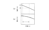
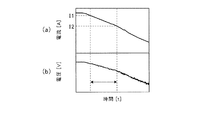
例えば、本実施例では、車両が走行中に減速した、又は停車状態から発進した、又は走行中に加速した状態であって、電流センサ23によって検出された電流値が図4(a)及び図5(a)に示すI1以下I2以上の範囲内である場合に、抵抗演算条件を満足している、すなわち抵抗演算開始条件が成立していると判断し、それ以外の場合には抵抗演算開始条件が成立していないと判断することとする。 For example, in the present embodiment, the current value detected by the current sensor 23 in the state where the vehicle is decelerated during traveling, started from a stopped state, or accelerated during traveling is shown in FIGS. When the resistance calculation condition is satisfied, i.e., the resistance calculation start condition is satisfied when it is within the range of I1 or less and I2 or more shown in 5 (a), the resistance calculation is started otherwise. It is determined that the condition is not satisfied.
ステップP5において、抵抗演算開始条件が成立していない場合(NO)、例えば図3(a)に示すt0〜t1,t2〜t3,t4〜t5等のように抵抗演算条件がオフとなりステップP4の処理に戻る。 In step P5, if the resistance calculation start condition is not satisfied (NO), the resistance calculation condition is turned off, for example, t0 to t1, t2 to t3, t4 to t5, etc. shown in FIG. Return to processing.
一方、ステップP5において、抵抗演算開始条件が成立している場合(YES)、例えば図3(a)に示すt1〜t2,t3〜t4,t5〜t6等のように抵抗演算条件がオンとなり、電池セル1−jの抵抗値及び決定係数の演算を行う(ステップP6)。 On the other hand, if the resistance calculation start condition is satisfied in step P5 (YES), the resistance calculation condition is turned on, for example, t1 to t2, t3 to t4, t5 to t6, etc. shown in FIG. The resistance value and the determination coefficient of the battery cell 1-j are calculated (step P6).
ステップP6で電池セル1−jの抵抗値及び決定係数の演算を行ったら、続いて、抵抗演算終了条件が成立しているか否かの判定を行う(ステップP7)。抵抗演算終了条件は、上述した抵抗演算開始条件と相反する条件であり、抵抗演算開始条件が成立しない場合に、抵抗演算終了条件が成立していると判定される。 If the resistance value and the determination coefficient of the battery cell 1-j are calculated in Step P6, it is subsequently determined whether or not the resistance calculation end condition is satisfied (Step P7). The resistance calculation end condition is a condition contrary to the above-described resistance calculation start condition. When the resistance calculation start condition is not satisfied, it is determined that the resistance calculation end condition is satisfied.
ステップP7において、抵抗演算終了条件が成立していない場合(NO)は、ステップP6の処理に戻る。 In step P7, if the resistance calculation end condition is not satisfied (NO), the process returns to step P6.
すなわち、図3(a)〜図3(c)に示すように、抵抗演算条件がオンとなっている間、一定時間間隔で電池セル1−jの抵抗値と決定係数との演算が繰り返される。
ここで、車両が走行中に減速した場合、電圧センサ21−jによって検出された電池セル1−jの電圧値、及び、電流センサ23によって検出された電池セル1−jの電流値は、それぞれ図4(a)、図4(b)にその一例を示すように変化する。また、車両が停車状態から発進を開始した、又は走行中に加速した場合、電圧センサ21−jによって検出された電池セル1−jの電圧値、及び、電流センサ23によって検出された電池セル1−jの電流値は、それぞれ図5(a)、図5(b)にその一例を示すように変化する。
That is, as shown in FIGS. 3A to 3C, while the resistance calculation condition is on, the calculation of the resistance value and the determination coefficient of the battery cell 1-j is repeated at regular time intervals. .
Here, when the vehicle decelerates during traveling, the voltage value of the battery cell 1-j detected by the voltage sensor 21-j and the current value of the battery cell 1-j detected by the current sensor 23 are respectively It changes so that the example may be shown to Fig.4 (a) and FIG.4 (b). In addition, when the vehicle starts to start from a stopped state or accelerates while traveling, the voltage value of the battery cell 1-j detected by the voltage sensor 21-j and the
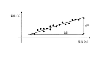
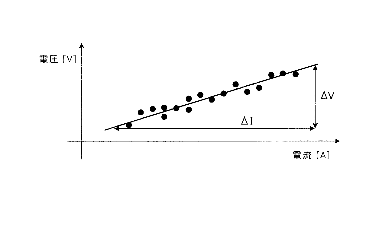
ここで、図6に示すように、x軸を電流I、y軸を電圧Vとし、電流Iと電圧Vとの関係が図6に実線で示すような関係である場合、抵抗Rはオームの法則により下式(1)により求められる。
R=ΔV/ΔI・・・(1)
Here, as shown in FIG. 6, when the x-axis is the current I, the y-axis is the voltage V, and the relationship between the current I and the voltage V is as shown by a solid line in FIG. It is obtained by the following equation (1) according to the law.
R = ΔV / ΔI (1)
しかしながら、実際には、抵抗演算条件がオンとなっている間、一定時間間隔で電圧センサ21−j、及び、電流センサ23から検出値を取得し、取得したデータをプロットすると、一つの電池セル1−jについて取得したデータであっても図6にドットで示すようにある程度のバラツキが生じる。そこで、本実施例では、下式(2)に示す近似式(最小二乗法)を用いて、図6に示す直線の傾きを演算し、これを電池セル1−jの抵抗演算値aとして算出する。 However, actually, when the resistance calculation condition is on, the detection values are acquired from the voltage sensor 21-j and the current sensor 23 at regular time intervals, and when the acquired data is plotted, one battery cell is obtained. Even in the data acquired for 1-j, some variation occurs as shown by dots in FIG. Therefore, in this embodiment, the slope of the straight line shown in FIG. 6 is calculated using the approximate expression (least square method) shown in the following expression (2), and this is calculated as the resistance calculation value a of the battery cell 1-j. To do.
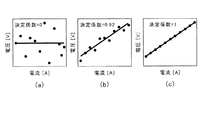
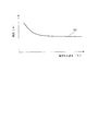
また、決定係数r2は上記(2)式により求めた電池セル1−jの抵抗演算値a(直線の傾き)の演算精度(例えば、図6に示す実線とドットとの関係性)を示す指標であり、下式(3)により算出する。 The determination coefficient r 2 indicates the calculation accuracy (for example, the relationship between the solid line and the dot shown in FIG. 6) of the resistance calculation value a (straight line) of the battery cell 1-j obtained by the above equation (2). It is an index and is calculated by the following formula (3).
上記(3)式からわかるように、決定係数r2は0から1の間の値となる。より詳しくは、図7(a)に示すようにプロットデータのバラツキが大きい場合、決定係数r2は0に近い値となり、図7(b)、図7(c)に示すようにプロットデータのバラツキが小さいほど決定係数r2は1に近い値となる。このように本実施例では、抵抗演算条件がオンとなっている間、一定時間間隔で取得した電圧センサ21−jによって検出された電池セル1−jの電圧値、及び、電流センサ23によって検出された電池セル1−jの電流値のプロットデータから決定係数r2を求め抵抗演算値aの演算精度を判断する。 As can be seen from the above equation (3), the determination coefficient r 2 is a value between 0 and 1. More specifically, when the variation of the plot data is large as shown in FIG. 7A, the determination coefficient r 2 becomes a value close to 0, and the plot data is changed as shown in FIGS. 7B and 7C. The smaller the variation is, the closer the determination coefficient r 2 is to 1. As described above, in this embodiment, while the resistance calculation condition is on, the voltage value of the battery cell 1-j detected by the voltage sensor 21-j acquired at a constant time interval and the current sensor 23 detect the voltage value. The coefficient of determination r 2 is obtained from the plot data of the current value of the battery cell 1-j, and the calculation accuracy of the resistance calculation value a is determined.
一方、ステップP7において、抵抗演算終了条件が成立している場合(YES)は、決定係数r2が演算精度の判定しきい値S1以上かつ演算精度の判定しきい値S2以下であるか否かの判定を行う(ステップP8)。ステップP8で決定係数r2が演算精度の判定しきい値S1未満または演算精度の判定しきい値S2より大きい場合(NO)は、ステップP4の処理に戻る。一方、ステップP8で決定係数r2が演算精度の判定しきい値S1以上かつ演算精度の判定しきい値S2以下である場合(YES)は、続いて抵抗出力値として抵抗演算値aの演算結果(抵抗演算結果)を出力する(ステップP9)。なお、本実施例では、ステップP8の処理において、抵抗演算条件がオンとなっている間、一度でも決定係数r2が演算精度の判定しきい値S1以上かつ演算精度の判定しきい値S2以下となった場合は、ステップP9に移行して抵抗演算結果を出力することとする。 On the other hand, in step P7, if the resistance calculation end condition is satisfied (YES), whether the coefficient of determination r 2 is equal to or less than the reference threshold value S2 in the determination threshold value S1 or greater and calculation accuracy of the arithmetic precision Is determined (step P8). Step If P8 in the coefficient of determination r 2 is greater than the determination threshold value S2 in the determination threshold S1 less than or arithmetic precision of arithmetic precision (NO), the process returns to step P4. On the other hand, if the coefficient of determination r 2 in step P8 is equal to or less than the reference threshold value S2 in the determination threshold value S1 or greater and calculation accuracy of the arithmetic precision (YES), followed by the operation result of the resistance calculation value a as a resistance output value (Resistance calculation result) is output (step P9). In the present embodiment, in the process of step P8, while the resistance calculation condition is ON, the coefficient of determination r 2 even once calculation accuracy of the determination threshold value S1 or more but the calculation accuracy determination threshold S2 below When it becomes, it will transfer to step P9 and it shall output a resistance calculation result.
ステップP9に続いては、抵抗演算結果が劣化判定しきい値S3以上か否かの判定を行う(ステップP10)。ここで、電池セル1−jの抵抗値は、温度によって変化するため、本実施例では、図8に示すように、電池セル1−jの温度に応じて劣化判定しきい値S3を選択するものとする。 Following step P9, it is determined whether or not the resistance calculation result is equal to or greater than the deterioration determination threshold value S3 (step P10). Here, since the resistance value of the battery cell 1-j varies depending on the temperature, in this embodiment, as shown in FIG. 8, the deterioration determination threshold value S3 is selected according to the temperature of the battery cell 1-j. Shall.
ステップP10で抵抗演算結果が劣化判定しきい値S3未満である場合(NO)は、ステップP3の処理に戻る。一方、ステップP10で抵抗演算結果が劣化判定しきい値S3以上である場合(YES)は、カウンタの値Cに1を加算し、C=C+1とする(ステップP11)。 When the resistance calculation result is less than the deterioration determination threshold value S3 in step P10 (NO), the process returns to step P3. On the other hand, if the resistance calculation result is greater than or equal to the degradation determination threshold value S3 in step P10 (YES), 1 is added to the counter value C to set C = C + 1 (step P11).
ステップP11に続いては、カウンタの値Cが警告しきい値S4以上か否かの判定を行う(ステップP12)。ステップP12でカウンタの値Cが警告しきい値S4未満の場合(NO)は、ステップP4の処理に戻る。一方、ステップP12でカウンタの値Cが警告しきい値S4以上である場合(YES)は、駆動用電池1が劣化していると判定し、電子制御装置3に対して表示計4に警告表示を行うよう指令を出力する(ステップP13)。
以上により、駆動用電池1(電池セル1−j)の劣化判定を行う。
Following step P11, it is determined whether the counter value C is equal to or greater than the warning threshold value S4 (step P12). If the counter value C is less than the warning threshold value S4 in step P12 (NO), the process returns to step P4. On the other hand, if the counter value C is greater than or equal to the warning threshold value S4 in step P12 (YES), it is determined that the driving
As described above, the deterioration of the driving battery 1 (battery cell 1-j) is determined.
以上の処理を図3を用いてより具体的に説明すると、本実施例に係る車両の駆動用電池劣化判定装置においては、時刻t1からt2までの間、図3(a)に示すように抵抗演算条件がオンとなっているため、図3(b)及び図3(c)に示すように電池セル1−jの抵抗演算値a及び決定係数r2の演算が一定時間間隔で繰り返される。この間、決定係数r2が演算精度の判定しきい値S1以上かつ演算精度の判定しきい値S2以下となっているため、図3(d)に示すように抵抗演算終了条件となった時刻t2の時点で電池セル1−jの抵抗演算値aが出力される。そして、この電池セル1−jの抵抗演算値aが劣化判定しきい値S3以上であるので、図3(e)に示すようにカウンタの値Cに1が加算されるとともに、図3(b)及び図3(c)に示すように抵抗演算値a及び決定係数r2がリセットされる。 The above process will be described more specifically with reference to FIG. 3. In the vehicle battery deterioration determination device for a vehicle according to the present embodiment, a resistance is applied as shown in FIG. 3A from time t1 to time t2. Since the calculation condition is on, the calculation of the resistance calculation value a and the determination coefficient r 2 of the battery cell 1-j is repeated at regular time intervals as shown in FIGS. 3 (b) and 3 (c). During this time, since the determination coefficient r 2 is equal to or higher than the calculation accuracy determination threshold value S1 and equal to or lower than the calculation accuracy determination threshold value S2, the time t2 when the resistance calculation end condition is satisfied as shown in FIG. At this point, the resistance calculation value a of the battery cell 1-j is output. Since the resistance calculation value a of the battery cell 1-j is equal to or greater than the deterioration determination threshold value S3, 1 is added to the counter value C as shown in FIG. ) And the resistance calculation value a and the determination coefficient r 2 are reset as shown in FIG.
また、図3に示す時刻t3からt4までの間、図3(a)に示すように抵抗演算条件がオンとなっているため、図3(b)及び図3(c)に示すように電池セル1−jの抵抗演算値a及び決定係数r2の演算が繰り返されるが、この間、決定係数r2が演算精度の判定しきい値S1未満となっているため、図3(d)に示すように抵抗演算終了条件となった時刻t4の時点で電池セル1−jの抵抗値の出力は行われず、図3(e)に示すようにカウンタの値Cがリセットされるとともに、図3(b)及び図3(c)に示すように抵抗演算値a及び決定係数r2がリセットされる。 Further, since the resistance calculation condition is on as shown in FIG. 3A from time t3 to t4 shown in FIG. 3, the battery as shown in FIG. 3B and FIG. The calculation of the resistance calculation value a and the determination coefficient r 2 of the cell 1-j is repeated. During this time, the determination coefficient r 2 is less than the determination threshold value S1 of the calculation accuracy, and therefore, as shown in FIG. As shown in FIG. 3E, the resistance value of the battery cell 1-j is not output at the time t4 when the resistance calculation end condition is satisfied, and the counter value C is reset as shown in FIG. As shown in b) and FIG. 3C, the resistance calculation value a and the determination coefficient r 2 are reset.
また、図3に示すt5からt6までの間、図3(a)に示すように抵抗演算条件がオンとなっているため、図3(b)及び図3(c)に示すように電池セル1−jの抵抗演算値及び決定係数の演算が繰り返される。この間、決定係数r2が演算精度の判定しきい値S1以上かつ演算精度の判定しきい値S2以下となっているため、図3(d)に示すように抵抗演算終了条件となった時刻t6の時点で電池セル1−jの抵抗演算値aが出力されるが、この電池セル1−jの抵抗演算値aが劣化判定しきい値S3未満であるので、図3(e)に示すようにカウンタの値Cがリセットされるとともに、図3(b)及び図3(c)に示すように電池セル1−jの抵抗演算値a及び決定係数r2がリセットされる。 Further, since the resistance calculation condition is on as shown in FIG. 3A from t5 to t6 shown in FIG. 3, the battery cell as shown in FIG. 3B and FIG. 3C. The calculation of the 1-j resistance calculation value and the determination coefficient is repeated. During this time, since the determination coefficient r 2 is equal to or higher than the calculation accuracy determination threshold value S1 and equal to or lower than the calculation accuracy determination threshold value S2, the time t6 when the resistance calculation end condition is reached as shown in FIG. As shown in FIG. 3E, the resistance calculation value a of the battery cell 1-j is output at the point of time, and the resistance calculation value a of the battery cell 1-j is less than the deterioration determination threshold value S3. The counter value C is reset at the same time, and the resistance calculation value a and the determination coefficient r 2 of the battery cell 1-j are reset as shown in FIGS. 3B and 3C.
以上のような処理が繰り返され、図3に示す時刻tmのようにカウンタの値Cが警告しきい値S4以上となったら図3(f)に示すように劣化判定フラグがオンとなり表示計4に警告が表示される。 When the above processing is repeated and the counter value C becomes equal to or higher than the warning threshold value S4 at time tm shown in FIG. 3, the deterioration determination flag is turned on as shown in FIG. Will display a warning.
ここで、本実施例においては、各電池セル1−jごとに抵抗演算値a及び決定係数r2の演算を行うものとする。本実施例のように各電池セル1−jごとに抵抗演算値a及び決定係数r2の演算を行えば、電池セル1−j単位での劣化判定が可能となる。ただし、抵抗演算値a及び決定係数r2の演算は上述した実施例に限定されるものではなく、各電池セル1−jごとに抵抗演算値a及び決定係数r2の演算を行うことに代えて、電池モジュール等の電池ユニットごとに抵抗演算値a及び決定係数r2の演算を行うようにしてもよい。 Here, in the present embodiment, the resistance calculation value a and the determination coefficient r 2 are calculated for each battery cell 1-j. If the resistance calculation value a and the determination coefficient r 2 are calculated for each battery cell 1-j as in the present embodiment, it is possible to determine deterioration in units of battery cells 1-j. However, the calculation of the resistance calculation value a and the determination coefficient r 2 is not limited to the above-described embodiment, and instead of calculating the resistance calculation value a and the determination coefficient r 2 for each battery cell 1-j. The resistance calculation value a and the determination coefficient r 2 may be calculated for each battery unit such as a battery module.
また、本実施例においては、抵抗演算条件を満足する電流値の範囲として、上限、下限をそれぞれI1,I2とする例を示したが、電流値の範囲は算出される抵抗値の演算精度を向上させることを目的として設定するものであるので、電流値の範囲の上限、下限は、上述したI1,I2以外であっても構わない。 Further, in the present embodiment, an example is shown in which the upper and lower limits are set to I1 and I2 as the current value range that satisfies the resistance calculation condition. However, the current value range indicates the calculation accuracy of the calculated resistance value. Since it is set for the purpose of improving, the upper limit and the lower limit of the range of the current value may be other than I1 and I2 described above.
さらに、本実施例においては、抵抗演算条件を、車両の状態が走行中に減速した、又は停車状態から発進した、又は走行中に加速した状態であって、且つ、電流センサ23によって検出された電流値があらかじめ設定した範囲内の値であることとしたが、抵抗演算条件は上述した実施例に限定されるものではなく、少なくとも車両の状態が走行中に減速した、又は停車状態から発進した、又は走行中に加速した状態であればよい。 Further, in this embodiment, the resistance calculation condition is a state in which the vehicle state is decelerated during traveling, started from a stopped state, or accelerated during traveling, and is detected by the current sensor 23. Although the current value is a value within a preset range, the resistance calculation condition is not limited to the above-described embodiment, and at least the state of the vehicle has decelerated during traveling or started from a stopped state. Or any state in which the vehicle is accelerated during traveling.
このように構成される本実施例に係る車両の駆動用電池劣化判定装置によれば、電流値及び電圧値にバラツキが生じやすい走行中であっても、各電池セル1−jの抵抗演算値aを高精度に算出し、駆動用電池1全体又は各電池セル1−jの劣化状態を正確に把握して高精度な劣化判定を行うことが可能となる。
According to the vehicle battery deterioration determination device for a vehicle according to the present embodiment configured as described above, even when the current value and the voltage value are likely to vary, the resistance calculation value of each battery cell 1-j. It is possible to calculate a with high accuracy, accurately grasp the deterioration state of the entire driving
また、抵抗演算条件に含まれる、予め設定した範囲内の電流値を抵抗値演算に用いることとし、電流値の範囲を、車両が走行中に減速した、又は停車状態から発進した、又は走行中に加速したときに安定して電流値が得られる範囲に予め設定することにより、電流値の範囲を設定しない場合と比較して、当該電流値を用いて算出される抵抗値の演算精度を向上させることができ、効率の良い電池劣化判定を行うことが可能となる。 In addition, the current value within a preset range included in the resistance calculation condition is used for the resistance value calculation, and the current value range is decelerated while the vehicle is traveling, started from a stopped state, or is traveling By setting the current value range in a stable manner when the current value is accelerated, the accuracy of the resistance value calculated using the current value is improved compared to when the current value range is not set. Therefore, efficient battery deterioration determination can be performed.
本発明は、走行中に駆動用電池の劣化状態を判定する車両の駆動用電池劣化判定装置に適用して好適なものである。 The present invention is suitable for application to a vehicle drive battery deterioration determination apparatus that determines a deterioration state of a drive battery during traveling.
1 駆動用電池
1−j(j=1,2,…,n) 電池セル
2 モータ
3 電子制御装置
4 表示計
11 演算装置
12 カウンタ
21−j(j=1,2,…,n) 電圧センサ
22−j(j=1,2,…,n) 温度センサ
23 電流センサ
24 車速センサ
25 モータスピードセンサ
26 ブレーキ油圧センサ
27 アクセル開度センサ
DESCRIPTION OF
Claims (7)
前記電池の電流値を検出する電流検出手段と、
前記電池の電圧値を検出する電圧検出手段と、
前記車両の走行中に、前記電流検出手段により検出した電流値と前記電圧検出手段により検出した電圧値とから一定時間間隔で前記電池の抵抗値を演算するとともに、算出された前記抵抗値の演算精度を演算し、前記演算精度が予め設定する演算精度の判定しきい値の範囲内にある場合に前記抵抗値に基づいて前記電池の劣化状態を判定する演算手段と
を備え、
前記演算手段は、カウンタを有し、前記抵抗値の演算結果が予め設定する劣化判定しきい値以上であった場合に前記カウンタの値に1を加算する一方、前記抵抗値の演算結果が前記劣化判定しきい値未満であった場合に前記カウンタをリセットし、前記カウンタの値が予め設定する警告しきい値以上となった場合に劣化判定を行う
たことを特徴とする車両の駆動用電池劣化判定装置。 A vehicle drive battery deterioration determination device for determining a deterioration state of a drive battery mounted on a vehicle,
Current detection means for detecting the current value of the battery;
Voltage detecting means for detecting a voltage value of the battery;
While the vehicle is running, the resistance value of the battery is calculated at regular intervals from the current value detected by the current detection means and the voltage value detected by the voltage detection means, and the calculated resistance value is calculated. A calculation means for calculating the accuracy, and determining the deterioration state of the battery based on the resistance value when the calculation accuracy is within a predetermined calculation accuracy determination threshold range ;
The calculation means includes a counter, and adds 1 to the value of the counter when the calculation result of the resistance value is greater than or equal to a preset deterioration determination threshold value, while the calculation result of the resistance value resets said counter if less than the deterioration determination threshold, wherein the value of the counter was <br/> performing the deterioration determination when equal to or larger than a warning threshold preset vehicle Drive battery deterioration determination device.
ことを特徴とする請求項1記載の車両の駆動用電池劣化判定装置。 The calculation means obtains plot data of current values and voltage values at regular time intervals from the current value detected by the current detection means and the voltage value detected by the voltage detection means while the vehicle is running. Determining the calculation accuracy of the resistance value from the plotted data, and determining the deterioration state of the battery based on the resistance value when the degree of variation of the plot data is within the determination threshold value range. The vehicle battery deterioration determining device for a vehicle according to claim 1.
前記演算手段は、前記車両の運転状態に基づき予め設定された抵抗演算条件が成立する場合に、前記電池の抵抗値の演算を行う
ことを特徴とする請求項1または2記載の車両の駆動用電池劣化判定装置。 Vehicle state detecting means for detecting the driving state of the vehicle,
3. The vehicle driving apparatus according to claim 1, wherein the calculation unit calculates a resistance value of the battery when a preset resistance calculation condition is established based on a driving state of the vehicle. Battery deterioration determination device.
ことを特徴とする請求項3に記載の車両の駆動用電池劣化判定装置。 4. The vehicle drive battery deterioration determination device according to claim 3, wherein the resistance calculation condition is determined to be satisfied when the driving state of the vehicle is a deceleration state, a start state, or an acceleration state. .
ことを特徴とする請求項4に記載の車両の駆動用電池劣化判定装置。 5. The vehicle drive battery deterioration according to claim 4, wherein the resistance calculation condition is determined to be satisfied when a current value detected by the current detection unit is within a predetermined range set in advance. Judgment device.
前記劣化判定しきい値は、前記電池の温度に応じて選択される
ことを特徴とする請求項1から請求項5のいずれか1項に記載の車両の駆動用電池劣化判定装置。 Temperature detecting means for detecting the temperature of the battery,
The vehicle drive battery deterioration determination device according to any one of claims 1 to 5, wherein the deterioration determination threshold value is selected according to a temperature of the battery.
ことを特徴とする請求項1から請求項6のいずれか1項に記載の車両の駆動用電池劣化判定装置。 The vehicle drive battery deterioration determination device according to any one of claims 1 to 6 , further comprising display means for displaying a deterioration state of the drive battery determined by the calculation means.
Priority Applications (2)
| Application Number | Priority Date | Filing Date | Title |
|---|---|---|---|
| JP2013268835A JP6263771B2 (en) | 2013-12-26 | 2013-12-26 | Vehicle drive battery deterioration determination device |
| US14/582,748 US9903919B2 (en) | 2013-12-26 | 2014-12-24 | Deterioration determination device for vehicle-driving battery |
Applications Claiming Priority (1)
| Application Number | Priority Date | Filing Date | Title |
|---|---|---|---|
| JP2013268835A JP6263771B2 (en) | 2013-12-26 | 2013-12-26 | Vehicle drive battery deterioration determination device |
Publications (2)
| Publication Number | Publication Date |
|---|---|
| JP2015126594A JP2015126594A (en) | 2015-07-06 |
| JP6263771B2 true JP6263771B2 (en) | 2018-01-24 |
Family
ID=53481406
Family Applications (1)
| Application Number | Title | Priority Date | Filing Date |
|---|---|---|---|
| JP2013268835A Active JP6263771B2 (en) | 2013-12-26 | 2013-12-26 | Vehicle drive battery deterioration determination device |
Country Status (2)
| Country | Link |
|---|---|
| US (1) | US9903919B2 (en) |
| JP (1) | JP6263771B2 (en) |
Families Citing this family (10)
| Publication number | Priority date | Publication date | Assignee | Title |
|---|---|---|---|---|
| US9625530B2 (en) * | 2014-03-26 | 2017-04-18 | Ford Global Technologies, Llc | Resistance based method and system to assess vehicle component integrity |
| JP2017055604A (en) * | 2015-09-10 | 2017-03-16 | ファナック株式会社 | Numerical control system displaying voltage value of battery for backup |
| CN106483467B (en) * | 2016-09-26 | 2020-01-21 | 北京百度网讯科技有限公司 | Electric vehicle state determination method and device |
| US10672199B2 (en) * | 2017-01-18 | 2020-06-02 | Ford Global Technologies, Llc | Method for monitoring component life |
| JP7069837B2 (en) | 2018-03-02 | 2022-05-18 | トヨタ自動車株式会社 | Battery diagnostic equipment and method |
| JP7003751B2 (en) | 2018-03-12 | 2022-01-21 | トヨタ自動車株式会社 | Battery diagnostic device and battery diagnostic method |
| WO2020075503A1 (en) * | 2018-10-12 | 2020-04-16 | ビークルエナジージャパン株式会社 | Battery control device |
| KR20220011852A (en) * | 2020-07-21 | 2022-02-03 | 현대자동차주식회사 | Detecting method for the battery use for a electronic vehicle |
| CN113155242A (en) * | 2021-03-23 | 2021-07-23 | 常州豪爵铃木摩托车有限公司 | Method and device for improving indication stability of fuel gauge and motorcycle |
| CN116291070A (en) * | 2023-03-22 | 2023-06-23 | 岚图汽车科技有限公司 | Electronic lock driving control method and device |
Family Cites Families (18)
| Publication number | Priority date | Publication date | Assignee | Title |
|---|---|---|---|---|
| JP3188100B2 (en) * | 1994-04-27 | 2001-07-16 | 株式会社日本自動車部品総合研究所 | Battery state detection method |
| US5939861A (en) * | 1996-05-24 | 1999-08-17 | Hino Jidosha Kogyo Kabushiki Kaisha | Control system for on-vehicle battery |
| JP4172222B2 (en) * | 2002-08-08 | 2008-10-29 | 日産自動車株式会社 | Control device for electric vehicle |
| JP4043978B2 (en) * | 2003-03-11 | 2008-02-06 | 株式会社日本自動車部品総合研究所 | Secondary battery internal resistance detection device, deterioration determination device, internal resistance detection method, and deterioration determination method |
| KR20070051916A (en) * | 2004-08-25 | 2007-05-18 | 닛본 덴끼 가부시끼가이샤 | Internal impedance detector, internal impedance detecting method, degradation degree detector, and degradation degree detecting method |
| JP4062301B2 (en) * | 2004-11-19 | 2008-03-19 | 株式会社デンソー | Vehicle power supply |
| JP4638251B2 (en) * | 2005-02-07 | 2011-02-23 | 富士重工業株式会社 | Battery management device |
| JP4286842B2 (en) * | 2005-03-30 | 2009-07-01 | 株式会社ピーシーエヌ | In-vehicle battery management device |
| WO2007032382A1 (en) * | 2005-09-16 | 2007-03-22 | The Furukawa Electric Co., Ltd | Secondary cell degradation judgment method, secondary cell degradation judgment device, and power supply system |
| JP4179330B2 (en) * | 2006-03-31 | 2008-11-12 | トヨタ自動車株式会社 | Battery information display device for hybrid vehicle |
| JP2010036718A (en) * | 2008-08-05 | 2010-02-18 | Mitsubishi Motors Corp | Battery deterioration determination device |
| JP5815195B2 (en) * | 2008-09-11 | 2015-11-17 | ミツミ電機株式会社 | Battery state detection device and battery pack incorporating the same |
| JP4821891B2 (en) * | 2009-07-01 | 2011-11-24 | トヨタ自動車株式会社 | Battery control system and vehicle |
| US9566875B2 (en) * | 2010-03-30 | 2017-02-14 | Honda Motor Co., Ltd. | Method of detecting battery capacity of secondary battery |
| JP2011257219A (en) * | 2010-06-08 | 2011-12-22 | Nissan Motor Co Ltd | Internal resistance of secondary battery and calculation device for calculating open voltage |
| JP5558941B2 (en) * | 2010-06-30 | 2014-07-23 | 三洋電機株式会社 | How to detect battery internal resistance |
| JP2013114735A (en) * | 2011-12-01 | 2013-06-10 | Hitachi-Lg Data Storage Inc | Library device, and method for controlling number of rotations of multiple cooling fans in library device |
| JP5626190B2 (en) * | 2011-12-02 | 2014-11-19 | トヨタ自動車株式会社 | Power storage system |
-
2013
- 2013-12-26 JP JP2013268835A patent/JP6263771B2/en active Active
-
2014
- 2014-12-24 US US14/582,748 patent/US9903919B2/en active Active
Also Published As
| Publication number | Publication date |
|---|---|
| JP2015126594A (en) | 2015-07-06 |
| US20150185290A1 (en) | 2015-07-02 |
| US9903919B2 (en) | 2018-02-27 |
Similar Documents
| Publication | Publication Date | Title |
|---|---|---|
| JP6263771B2 (en) | Vehicle drive battery deterioration determination device | |
| EP3214422B1 (en) | Electric-vehicle testing apparatus, method and computer program | |
| JP5231900B2 (en) | Method for controlling vehicle power system | |
| CN105365811B (en) | The method and apparatus for controlling the crawling torque of the vehicle to contain drive motor | |
| JP4506881B2 (en) | Control device for hybrid vehicle | |
| US20150323610A1 (en) | Battery management apparatus | |
| EP3100924B1 (en) | Method and apparatus for controlling plug-in hybrid electric vehicle, as well as computer-readable medium | |
| JP6605031B2 (en) | Electric vehicle moving direction detection | |
| CN104245455A (en) | Vehicle power-generator device and vehicle power-generation control method | |
| WO2012123862A3 (en) | Method and electronic system for the automatic management of the energy autonomy of a vehicle particularly of electric vehicles | |
| US10974788B2 (en) | Battery pack, battery system comprising the same, and method for distinguishing use application of battery pack | |
| KR101683525B1 (en) | Engine control device and method of hybrid vehicel | |
| JP6962826B2 (en) | Battery system | |
| CN109835345A (en) | Demand torque calculation method, demand torque computing device and automobile | |
| KR101611285B1 (en) | electric vehicle and control method thereof | |
| JP2017118766A (en) | Vehicular motor torque estimation apparatus | |
| KR101499745B1 (en) | Method for calculating fuel consumption of vehicle using equivalent fuel factor of kinetic energy | |
| JP2019108014A (en) | Cruising distance estimation device | |
| KR101673747B1 (en) | Apparatus for displaying eco guide in vehicle cluster and method thereof | |
| JP2014054124A (en) | Electric vehicle cruisable length calculation device | |
| JP7174347B2 (en) | Remaining drivable distance calculation device | |
| CN107757627B (en) | Vehicle control device and information providing method | |
| JP2015230742A (en) | Lithium ion battery system | |
| JP2016094139A (en) | Vehicle speed estimation device of four-wheel drive vehicle and control device | |
| JP2012017986A (en) | Vehicle weight calculation device |
Legal Events
| Date | Code | Title | Description |
|---|---|---|---|
| A621 | Written request for application examination |
Free format text: JAPANESE INTERMEDIATE CODE: A621 Effective date: 20160923 |
|
| A977 | Report on retrieval |
Free format text: JAPANESE INTERMEDIATE CODE: A971007 Effective date: 20170614 |
|
| A131 | Notification of reasons for refusal |
Free format text: JAPANESE INTERMEDIATE CODE: A131 Effective date: 20170620 |
|
| A521 | Written amendment |
Free format text: JAPANESE INTERMEDIATE CODE: A523 Effective date: 20170711 |
|
| TRDD | Decision of grant or rejection written | ||
| A01 | Written decision to grant a patent or to grant a registration (utility model) |
Free format text: JAPANESE INTERMEDIATE CODE: A01 Effective date: 20171114 |
|
| RD03 | Notification of appointment of power of attorney |
Free format text: JAPANESE INTERMEDIATE CODE: A7423 Effective date: 20171114 |
|
| A61 | First payment of annual fees (during grant procedure) |
Free format text: JAPANESE INTERMEDIATE CODE: A61 Effective date: 20171127 |
|
| R151 | Written notification of patent or utility model registration |
Ref document number: 6263771 Country of ref document: JP Free format text: JAPANESE INTERMEDIATE CODE: R151 |
|
| S531 | Written request for registration of change of domicile |
Free format text: JAPANESE INTERMEDIATE CODE: R313531 |
|
| R350 | Written notification of registration of transfer |
Free format text: JAPANESE INTERMEDIATE CODE: R350 |