JP6262216B2 - System and method for avoiding collision between operating arms using null space - Google Patents
System and method for avoiding collision between operating arms using null space Download PDFInfo
- Publication number
- JP6262216B2 JP6262216B2 JP2015515231A JP2015515231A JP6262216B2 JP 6262216 B2 JP6262216 B2 JP 6262216B2 JP 2015515231 A JP2015515231 A JP 2015515231A JP 2015515231 A JP2015515231 A JP 2015515231A JP 6262216 B2 JP6262216 B2 JP 6262216B2
- Authority
- JP
- Japan
- Prior art keywords
- manipulator
- joint
- joints
- manipulator arm
- arm
- Prior art date
- Legal status (The legal status is an assumption and is not a legal conclusion. Google has not performed a legal analysis and makes no representation as to the accuracy of the status listed.)
- Active
Links
- 238000000034 method Methods 0.000 title description 31
- 239000012636 effector Substances 0.000 claims description 109
- 230000009471 action Effects 0.000 claims description 59
- 239000013598 vector Substances 0.000 claims description 55
- 238000006073 displacement reaction Methods 0.000 claims description 23
- 238000001356 surgical procedure Methods 0.000 claims description 22
- 230000004044 response Effects 0.000 claims description 21
- 238000003780 insertion Methods 0.000 claims description 18
- 230000037431 insertion Effects 0.000 claims description 18
- 238000000926 separation method Methods 0.000 claims description 12
- 238000004364 calculation method Methods 0.000 claims description 11
- 230000008878 coupling Effects 0.000 claims description 9
- 238000010168 coupling process Methods 0.000 claims description 9
- 238000005859 coupling reaction Methods 0.000 claims description 9
- 230000000694 effects Effects 0.000 claims description 7
- 230000001133 acceleration Effects 0.000 claims description 4
- 238000005096 rolling process Methods 0.000 claims 1
- 230000006870 function Effects 0.000 description 17
- 238000010586 diagram Methods 0.000 description 11
- 230000003993 interaction Effects 0.000 description 9
- 230000008569 process Effects 0.000 description 8
- 230000008901 benefit Effects 0.000 description 7
- 238000002432 robotic surgery Methods 0.000 description 7
- 238000003384 imaging method Methods 0.000 description 6
- 230000006872 improvement Effects 0.000 description 5
- 238000013507 mapping Methods 0.000 description 5
- 238000013459 approach Methods 0.000 description 4
- 210000003815 abdominal wall Anatomy 0.000 description 3
- 230000002452 interceptive effect Effects 0.000 description 3
- 230000000712 assembly Effects 0.000 description 2
- 238000000429 assembly Methods 0.000 description 2
- 230000008859 change Effects 0.000 description 2
- 238000004891 communication Methods 0.000 description 2
- 238000003745 diagnosis Methods 0.000 description 2
- 230000007717 exclusion Effects 0.000 description 2
- 230000003287 optical effect Effects 0.000 description 2
- 230000008447 perception Effects 0.000 description 2
- 238000012545 processing Methods 0.000 description 2
- 239000007787 solid Substances 0.000 description 2
- 210000000707 wrist Anatomy 0.000 description 2
- 235000000177 Indigofera tinctoria Nutrition 0.000 description 1
- 230000006978 adaptation Effects 0.000 description 1
- 230000002411 adverse Effects 0.000 description 1
- 230000004075 alteration Effects 0.000 description 1
- 210000003484 anatomy Anatomy 0.000 description 1
- 230000009286 beneficial effect Effects 0.000 description 1
- 230000001808 coupling effect Effects 0.000 description 1
- 230000001419 dependent effect Effects 0.000 description 1
- 238000013461 design Methods 0.000 description 1
- 229940097275 indigo Drugs 0.000 description 1
- COHYTHOBJLSHDF-UHFFFAOYSA-N indigo powder Natural products N1C2=CC=CC=C2C(=O)C1=C1C(=O)C2=CC=CC=C2N1 COHYTHOBJLSHDF-UHFFFAOYSA-N 0.000 description 1
- 208000014674 injury Diseases 0.000 description 1
- 238000009434 installation Methods 0.000 description 1
- 230000009916 joint effect Effects 0.000 description 1
- 238000002357 laparoscopic surgery Methods 0.000 description 1
- 239000011159 matrix material Substances 0.000 description 1
- 230000007246 mechanism Effects 0.000 description 1
- 238000002324 minimally invasive surgery Methods 0.000 description 1
- 238000012986 modification Methods 0.000 description 1
- 230000004048 modification Effects 0.000 description 1
- 238000011022 operating instruction Methods 0.000 description 1
- 238000011084 recovery Methods 0.000 description 1
- 230000009467 reduction Effects 0.000 description 1
- 230000001846 repelling effect Effects 0.000 description 1
- 239000000523 sample Substances 0.000 description 1
- 238000012549 training Methods 0.000 description 1
- 230000009466 transformation Effects 0.000 description 1
- 230000008733 trauma Effects 0.000 description 1
Images


Classifications
-
- A—HUMAN NECESSITIES
- A61—MEDICAL OR VETERINARY SCIENCE; HYGIENE
- A61B—DIAGNOSIS; SURGERY; IDENTIFICATION
- A61B34/00—Computer-aided surgery; Manipulators or robots specially adapted for use in surgery
- A61B34/30—Surgical robots
-
- A—HUMAN NECESSITIES
- A61—MEDICAL OR VETERINARY SCIENCE; HYGIENE
- A61B—DIAGNOSIS; SURGERY; IDENTIFICATION
- A61B34/00—Computer-aided surgery; Manipulators or robots specially adapted for use in surgery
- A61B34/30—Surgical robots
- A61B34/35—Surgical robots for telesurgery
-
- A—HUMAN NECESSITIES
- A61—MEDICAL OR VETERINARY SCIENCE; HYGIENE
- A61B—DIAGNOSIS; SURGERY; IDENTIFICATION
- A61B34/00—Computer-aided surgery; Manipulators or robots specially adapted for use in surgery
- A61B34/30—Surgical robots
- A61B34/37—Master-slave robots
-
- A—HUMAN NECESSITIES
- A61—MEDICAL OR VETERINARY SCIENCE; HYGIENE
- A61B—DIAGNOSIS; SURGERY; IDENTIFICATION
- A61B34/00—Computer-aided surgery; Manipulators or robots specially adapted for use in surgery
- A61B34/70—Manipulators specially adapted for use in surgery
-
- A—HUMAN NECESSITIES
- A61—MEDICAL OR VETERINARY SCIENCE; HYGIENE
- A61B—DIAGNOSIS; SURGERY; IDENTIFICATION
- A61B90/00—Instruments, implements or accessories specially adapted for surgery or diagnosis and not covered by any of the groups A61B1/00 - A61B50/00, e.g. for luxation treatment or for protecting wound edges
- A61B90/03—Automatic limiting or abutting means, e.g. for safety
-
- B—PERFORMING OPERATIONS; TRANSPORTING
- B25—HAND TOOLS; PORTABLE POWER-DRIVEN TOOLS; MANIPULATORS
- B25J—MANIPULATORS; CHAMBERS PROVIDED WITH MANIPULATION DEVICES
- B25J13/00—Controls for manipulators
- B25J13/06—Control stands, e.g. consoles, switchboards
-
- B—PERFORMING OPERATIONS; TRANSPORTING
- B25—HAND TOOLS; PORTABLE POWER-DRIVEN TOOLS; MANIPULATORS
- B25J—MANIPULATORS; CHAMBERS PROVIDED WITH MANIPULATION DEVICES
- B25J17/00—Joints
-
- B—PERFORMING OPERATIONS; TRANSPORTING
- B25—HAND TOOLS; PORTABLE POWER-DRIVEN TOOLS; MANIPULATORS
- B25J—MANIPULATORS; CHAMBERS PROVIDED WITH MANIPULATION DEVICES
- B25J9/00—Programme-controlled manipulators
- B25J9/06—Programme-controlled manipulators characterised by multi-articulated arms
-
- B—PERFORMING OPERATIONS; TRANSPORTING
- B25—HAND TOOLS; PORTABLE POWER-DRIVEN TOOLS; MANIPULATORS
- B25J—MANIPULATORS; CHAMBERS PROVIDED WITH MANIPULATION DEVICES
- B25J9/00—Programme-controlled manipulators
- B25J9/16—Programme controls
- B25J9/1602—Programme controls characterised by the control system, structure, architecture
- B25J9/1607—Calculation of inertia, jacobian matrixes and inverses
-
- B—PERFORMING OPERATIONS; TRANSPORTING
- B25—HAND TOOLS; PORTABLE POWER-DRIVEN TOOLS; MANIPULATORS
- B25J—MANIPULATORS; CHAMBERS PROVIDED WITH MANIPULATION DEVICES
- B25J9/00—Programme-controlled manipulators
- B25J9/16—Programme controls
- B25J9/1628—Programme controls characterised by the control loop
- B25J9/1643—Programme controls characterised by the control loop redundant control
-
- B—PERFORMING OPERATIONS; TRANSPORTING
- B25—HAND TOOLS; PORTABLE POWER-DRIVEN TOOLS; MANIPULATORS
- B25J—MANIPULATORS; CHAMBERS PROVIDED WITH MANIPULATION DEVICES
- B25J9/00—Programme-controlled manipulators
- B25J9/16—Programme controls
- B25J9/1674—Programme controls characterised by safety, monitoring, diagnostic
- B25J9/1676—Avoiding collision or forbidden zones
-
- A—HUMAN NECESSITIES
- A61—MEDICAL OR VETERINARY SCIENCE; HYGIENE
- A61B—DIAGNOSIS; SURGERY; IDENTIFICATION
- A61B17/00—Surgical instruments, devices or methods, e.g. tourniquets
- A61B2017/00017—Electrical control of surgical instruments
- A61B2017/00199—Electrical control of surgical instruments with a console, e.g. a control panel with a display
-
- A—HUMAN NECESSITIES
- A61—MEDICAL OR VETERINARY SCIENCE; HYGIENE
- A61B—DIAGNOSIS; SURGERY; IDENTIFICATION
- A61B34/00—Computer-aided surgery; Manipulators or robots specially adapted for use in surgery
- A61B34/30—Surgical robots
- A61B2034/305—Details of wrist mechanisms at distal ends of robotic arms
-
- G—PHYSICS
- G05—CONTROLLING; REGULATING
- G05B—CONTROL OR REGULATING SYSTEMS IN GENERAL; FUNCTIONAL ELEMENTS OF SUCH SYSTEMS; MONITORING OR TESTING ARRANGEMENTS FOR SUCH SYSTEMS OR ELEMENTS
- G05B2219/00—Program-control systems
- G05B2219/30—Nc systems
- G05B2219/39—Robotics, robotics to robotics hand
- G05B2219/39091—Avoid collision with moving obstacles
-
- G—PHYSICS
- G05—CONTROLLING; REGULATING
- G05B—CONTROL OR REGULATING SYSTEMS IN GENERAL; FUNCTIONAL ELEMENTS OF SUCH SYSTEMS; MONITORING OR TESTING ARRANGEMENTS FOR SUCH SYSTEMS OR ELEMENTS
- G05B2219/00—Program-control systems
- G05B2219/30—Nc systems
- G05B2219/39—Robotics, robotics to robotics hand
- G05B2219/39135—For multiple manipulators operating at same time, avoid collision
-
- G—PHYSICS
- G05—CONTROLLING; REGULATING
- G05B—CONTROL OR REGULATING SYSTEMS IN GENERAL; FUNCTIONAL ELEMENTS OF SUCH SYSTEMS; MONITORING OR TESTING ARRANGEMENTS FOR SUCH SYSTEMS OR ELEMENTS
- G05B2219/00—Program-control systems
- G05B2219/30—Nc systems
- G05B2219/40—Robotics, robotics mapping to robotics vision
- G05B2219/40202—Human robot coexistence
-
- G—PHYSICS
- G05—CONTROLLING; REGULATING
- G05B—CONTROL OR REGULATING SYSTEMS IN GENERAL; FUNCTIONAL ELEMENTS OF SUCH SYSTEMS; MONITORING OR TESTING ARRANGEMENTS FOR SUCH SYSTEMS OR ELEMENTS
- G05B2219/00—Program-control systems
- G05B2219/30—Nc systems
- G05B2219/40—Robotics, robotics mapping to robotics vision
- G05B2219/40362—Elbow high or low, avoid obstacle collision with redundancy control
-
- G—PHYSICS
- G05—CONTROLLING; REGULATING
- G05B—CONTROL OR REGULATING SYSTEMS IN GENERAL; FUNCTIONAL ELEMENTS OF SUCH SYSTEMS; MONITORING OR TESTING ARRANGEMENTS FOR SUCH SYSTEMS OR ELEMENTS
- G05B2219/00—Program-control systems
- G05B2219/30—Nc systems
- G05B2219/40—Robotics, robotics mapping to robotics vision
- G05B2219/40371—Control trajectory to avoid joint limit as well as obstacle collision
-
- G—PHYSICS
- G05—CONTROLLING; REGULATING
- G05B—CONTROL OR REGULATING SYSTEMS IN GENERAL; FUNCTIONAL ELEMENTS OF SUCH SYSTEMS; MONITORING OR TESTING ARRANGEMENTS FOR SUCH SYSTEMS OR ELEMENTS
- G05B2219/00—Program-control systems
- G05B2219/30—Nc systems
- G05B2219/40—Robotics, robotics mapping to robotics vision
- G05B2219/40476—Collision, planning for collision free path
-
- G—PHYSICS
- G05—CONTROLLING; REGULATING
- G05B—CONTROL OR REGULATING SYSTEMS IN GENERAL; FUNCTIONAL ELEMENTS OF SUCH SYSTEMS; MONITORING OR TESTING ARRANGEMENTS FOR SUCH SYSTEMS OR ELEMENTS
- G05B2219/00—Program-control systems
- G05B2219/30—Nc systems
- G05B2219/40—Robotics, robotics mapping to robotics vision
- G05B2219/40492—Model manipulator by spheres for collision avoidance
-
- G—PHYSICS
- G05—CONTROLLING; REGULATING
- G05B—CONTROL OR REGULATING SYSTEMS IN GENERAL; FUNCTIONAL ELEMENTS OF SUCH SYSTEMS; MONITORING OR TESTING ARRANGEMENTS FOR SUCH SYSTEMS OR ELEMENTS
- G05B2219/00—Program-control systems
- G05B2219/30—Nc systems
- G05B2219/45—Nc applications
- G05B2219/45117—Medical, radio surgery manipulator
Description
(関連出願の参照)
この出願は2012年6月1日に出願された「Systems and Methods for Avoiding Collisions Between Manipulator Arms Using a Null-Space」という名称の米国仮特許出願番号第61/654,773号の利益を主張する非仮出願であり、その全文をここに参照として援用する。
(Refer to related applications)
This application claims the benefit of US Provisional Patent Application No. 61 / 654,773, filed June 1, 2012, entitled “Systems and Methods for Avoiding Collisions Between Manipulator Arms Using a Null-Space”. This is a provisional application, which is incorporated herein by reference in its entirety.
本出願は以下の同一所有の出願、即ち、2009年6月30日に出願された「Control of Medical Robotic System Manipulator About Kinematic Singularities」という名称の米国特許出願第12/494,695号、2009年3月17日に出願された「Master Controller Having Redundant Degrees of Freedom and Added Forces to Create Internal Motion」という名称の米国特許出願12/406,004号、2005年5月19に出願された「Software Center and Highly Configurable Robotic Systems for Surgery and Other Uses」という名称の米国特許出願第11/133,423号(米国特許第8,004,229号)、2004年9月30日に出願された「Offset Remote Center Manipulator For Robotic Surgery」という名称の米国特許出願第10/957,077号(米国特許第7,594,912号)、2001年8月13日に出願された「Surgical Robotic Tools, Data Architecture, and Use」という名称の米国特許出願第09/929,453号(米国特許第7,048,745号)、1999年9月17日に出願された「Master Having Redundant Degrees of Freedom」という名称の米国特許出願第09/398,507号(米国特許第6,714,839号)、並びに、本出願と同時に出願された「Manipulator Arm-to-Patient Collision Avoidance Using a Null-Space」という名称の米国特許出願第_号(代理人整理番号ISRG03760/US)及び「System and Methods for Commanded Reconfiguration of a Surgical Manipulator Using the Null-Space」という名称の米国特許出願第_号(代理人整理番号ISRG03770/US)に概ね関係し、それらの開示の全文をここに参照として援用する。 This application is the following commonly owned application: US patent application Ser. No. 12 / 494,695, entitled “Control of Medical Robotic System Manipulator About Kinematic Singularities,” filed June 30, 2009, March 2009. US Patent Application No. 12 / 406,004 entitled “Master Controller Having Redundant Degrees of Freedom and Added Forces to Create Internal Motion” filed May 17, 2005, “Software Center and Highly No. 11 / 133,423 (U.S. Pat. No. 8,004,229) entitled “Configurable Robotic Systems for Surgery and Other Uses”, “Offset Remote Center Manipulator For” filed on September 30, 2004 US patent application Ser. No. 10 / 957,077 entitled “Robotic Surgery” (US Pat. No. 7,594,912) No. 09 / 929,453 (US Pat. No. 7,048,745), 1999, filed Aug. 13, 2001, entitled “Surgical Robotic Tools, Data Architecture, and Use”. US patent application Ser. No. 09 / 398,507 (US Pat. No. 6,714,839) entitled “Master Having Redundant Degrees of Freedom” filed on September 17, 1995, and filed concurrently with this application US Patent Application No. _ (Attorney Docket Number ISRG03760 / US) entitled “Manipulator Arm-to-Patient Collision Avoidance Using a Null-Space” and “System and Methods for Commanded Reconfiguration of a Surgical Manipulator Using the Null-Space” Commonly related to US Patent Application No. _ "Space Name" (Attorney Docket Number ISRG03770 / US), see here the full text of their disclosure And incorporated by.
本出願は、手術及び/又はロボット装置、システム、並びに方法の改良を概ね提供する。 The present application generally provides improvements in surgical and / or robotic devices, systems, and methods.
最小侵襲的医療技法は診断又は外科手術中に損傷させられる組織の量を減少させ、それにより、患者の回復時間、不快感、及び有害な副作用を減少させることに向けられている。何百万の「観血的」又は従来的な手術が米国内で毎年執り行われており、それらの多くは潜在的には最小侵襲的な方法において執り行われ得る。しかしながら、現在のところ、手術器具、技法、及び最小侵襲的技法に熟達するために必要とされる追加的な外科訓練の故に、比較的少数の手術のみが最小侵襲的技法を用いている。 Minimally invasive medical techniques are directed to reducing the amount of tissue that is damaged during diagnosis or surgery, thereby reducing patient recovery time, discomfort, and adverse side effects. Millions of “open” or conventional surgery are performed annually in the United States, many of which can potentially be performed in a minimally invasive manner. Currently, however, only a relatively small number of surgeries use minimally invasive techniques because of the additional surgical training required to master surgical instruments, techniques, and minimally invasive techniques.
外科医の器用さを増大させるために並びに外科医が遠隔場所から患者を手術することを可能にするために、手術における使用のための最小侵襲的遠隔手術システムが開発されている。遠隔手術は、手術器具を手で直接的に保持し且つ移動させるよりもむしろ手術器具の動作を操作するために、外科医が何らかの形態の遠隔制御、例えば、サーボ機構又は同種のものを使用する、手術システムのための一般用語である。そのような遠隔手術システムにおいて、外科医には遠隔場所で手術部位の画像が提供される。適切なビューア又はディスプレイ上で手術部位の典型的には三次元画像を見ながら、外科医は、ひいてはロボット器具の動作を制御するマスタ制御入力装置を操作することによって、患者に対する外科手術を執り行う。患者内の手術部位で組織を処置するよう、ロボット手術器具を小さな最小侵襲的な手術孔を通じて挿入することができ、観血的手術のために接近することに外傷が頻繁に付随する。これらのロボットシステムは、しばしば、最小侵襲的孔で器具のシャフトを旋回させること、孔を通じてシャフトを軸方向に滑動させること、シャフトを孔内で回転させること、及び/又は同種のことによって、極めて複雑な外科的仕事を執り行うために十分な器用さで手術器具の作動端を移動させ得る。 Minimally invasive telesurgical systems for use in surgery have been developed to increase surgeon dexterity as well as to allow surgeons to operate a patient from a remote location. Telesurgery uses some form of remote control, such as a servomechanism or the like, to manipulate the operation of the surgical instrument rather than holding and moving the surgical instrument directly by hand, A general term for a surgical system. In such a telesurgical system, the surgeon is provided with an image of the surgical site at a remote location. While viewing a typically three-dimensional image of the surgical site on a suitable viewer or display, the surgeon performs the surgical operation on the patient by manipulating a master control input device that in turn controls the operation of the robotic instrument. Robotic surgical instruments can be inserted through small, minimally invasive surgical holes to treat tissue at the surgical site within a patient, and trauma often accompanies access for open surgery. These robotic systems are often extremely powerful by pivoting the instrument shaft with a minimally invasive hole, sliding the shaft axially through the hole, rotating the shaft within the hole, and / or the like. The working end of the surgical instrument can be moved with sufficient dexterity to perform complex surgical tasks.
遠隔手術のために用いられるサーボ機構は、2つのマスタコントローラ(外科医の各々の手のために各1つ)から入力を頻繁に受け入れ、2つ又はそれよりも多くのロボットアーム又はマニピュレータを含み得る。画像捕捉装置によって表示されるロボット器具の画像への手動作のマッピングは、外科医に各手と関連付けられる器具に対する正確な制御をもたらすことに役立ち得る。内視鏡若しくは他の類似の画像捕捉装置、追加的な手術器具、又は同種のものを移動させるために、多くの手術ロボットシステムには、1つ又はそれよりも多くの追加的なロボット操作アームが含まれる。 Servo mechanisms used for telesurgery frequently accept input from two master controllers (one for each surgeon's hand) and may include two or more robot arms or manipulators . The mapping of hand movements to images of robotic instruments displayed by the image capture device can help provide the surgeon precise control over the instruments associated with each hand. In order to move an endoscope or other similar image capture device, additional surgical instrument, or the like, many surgical robotic systems include one or more additional robotic operating arms. Is included.
ロボット手術中に手術部位で手術器具を支持するために、様々の構造的配置を用い得る。被駆動リンク又は「スレーブ」はロボット手術マニピュレータと呼ばれることが多く、最小侵襲的ロボット手術中のロボット手術マニピュレータとしての使用のための例示的なリンク配置は、米国特許第6,758,843号、第6,246,200号、及び第5,800,423号中に記載されており、それらの全開示をここに参照として援用する。これらのリンクは、シャフトを有する器具を保持するために平行四辺形の配置を頻繁に使用する。そのようなマニピュレータ構造は、器具のシャフトが剛的なシャフトの長さに沿う空間内に位置付けられる球回転の遠隔中心について旋回するよう、器具の動作を制約し得る。(例えば、腹腔鏡手術中に腹壁でトロカール又はカニューレを用いて)この回転の中心を内部手術部位への切開地点に整列させることによって、潜在的に危険な力を腹壁に課すことなく、マニピュレータリンクを用いてシャフトの近位端を移動させることによって、手術器具のエンドエフェクタを安全に位置付け得る。代替的なマニピュレータ構造が、例えば、米国特許第6,702,805号、第6,676,669号、第5,855,583号、第5,808,665号、第5,445,166号、及び第5,184,601号に記載されており、それらの全開示をここに干渉として援用する。 Various structural arrangements can be used to support the surgical instrument at the surgical site during robotic surgery. Driven links or “slaves” are often referred to as robotic surgical manipulators, and exemplary link arrangements for use as robotic surgical manipulators during minimally invasive robotic surgery are described in US Pat. No. 6,758,843, Nos. 6,246,200 and 5,800,423, the entire disclosures of which are incorporated herein by reference. These links frequently use a parallelogram arrangement to hold an instrument with a shaft. Such a manipulator structure may constrain the operation of the instrument such that the instrument shaft pivots about a remote center of ball rotation that is positioned in space along the length of the rigid shaft. By aligning the center of rotation with the incision point to the internal surgical site (eg, using a trocar or cannula on the abdominal wall during laparoscopic surgery), the manipulator link without imposing a potentially dangerous force on the abdominal wall Can be used to safely position the end effector of the surgical instrument by moving the proximal end of the shaft. Alternative manipulator structures are described, for example, in US Pat. Nos. 6,702,805, 6,676,669, 5,855,583, 5,808,665, and 5,445,166. And 5,184,601, the entire disclosures of which are incorporated herein by reference.
新しいロボット手術システム及び装置は極めて効果的であり且つ有利であることが証明されているが、更なる改良が依然として望ましい。例えば、手術器具を最小侵襲的な手術部位内で移動させるとき、ロボット手術マニピュレータは、特に大きな角度範囲を通じて最小非侵襲孔について器具を旋回させるときに患者の外側で有意な量の動作を示すことがあり、それは移動するマニピュレータが偶発的に互いに接触し合い、手術室内の器具カート若しくは他の器具と接触し、外科人員と接触し、且つ/或いは患者の他の表面と接触するようになることを引き起こし得る。具体的には、マニピュレータアームの体積は隣接するマニピュレータアームと接触し或いは衝突することがあり、それはマニピュレータアームに対する望ましくない動作及び/又は応力を引き起こし得る。患者(又は同種のもの)の外側での偶発的なマニピュレータ/マニピュレータ接触を抑制しながら、挿入部位への旋回運動を制約するよう設定される高度に構成可能な運動力学的マニピュレータ継手に対するソフトウェア制御を利用する、代替的なマニピュレータ構造が提案されている。これらの高度に構成可能な「ソフトウェアセンタ」手術マニピュレータシステムは有意な利点をもたらし得るが、挑戦も提示し得る。具体的には、機械的に制約された遠隔中心リンクは、一部の状況において安全利点を有し得る。加えて、これらのマニピュレータに頻繁に含められる多数の継手の広範囲の設定は、特定の手術のために望ましい設定において手動で据え付けるのが困難であるマニピュレータをもたらし得る。それにも拘わらず、遠隔手術システムを用いて執り行われる手術の範囲は拡大し続けているので、利用可能な設計及び患者内の器具の動作範囲を拡張することに関する益々の要求がある。残念ながら、これらの変更の両方は、体の外側でマニピュレータの動作を制御し且つ予測することに関連付けられる挑戦を増大させることがあり、マニピュレータアーム及び隣接するマニピュレータアームの構成部品間の望ましくない接触又は衝突を回避することの重要性を増大させる。 Although new robotic surgical systems and devices have proven to be extremely effective and advantageous, further improvements are still desirable. For example, when moving a surgical instrument within a minimally invasive surgical site, the robotic surgical manipulator will show a significant amount of movement outside the patient, especially when pivoting the instrument about a minimally non-invasive hole through a large angular range That causes the moving manipulators to accidentally contact each other, contact an instrument cart or other instrument in the operating room, contact surgical personnel, and / or contact other surfaces of the patient Can cause. In particular, the volume of a manipulator arm can contact or collide with an adjacent manipulator arm, which can cause undesirable movement and / or stress on the manipulator arm. Software control over highly configurable kinematic manipulator joints set to constrain pivoting motion to the insertion site while suppressing accidental manipulator / manipulator contact outside the patient (or the like) Alternative manipulator structures have been proposed for use. These highly configurable “software center” surgical manipulator systems can offer significant advantages, but can also present challenges. In particular, a mechanically constrained remote central link may have a safety advantage in some situations. In addition, the extensive setting of the multiple joints frequently included in these manipulators can result in manipulators that are difficult to manually install in the desired settings for a particular surgery. Nevertheless, as the scope of surgery performed with telesurgical systems continues to expand, there is an increasing demand for extending the available design and operating range of instruments within the patient. Unfortunately, both of these changes can increase the challenges associated with controlling and predicting manipulator movement outside the body, and undesirable contact between the manipulator arm and adjacent manipulator arm components. Or increase the importance of avoiding collisions.
これらの及び他の理由のために、手術、ロボット手術、及び他のロボット用途のための改良された装置、システム、及び方法を提供することが有利である。これらの改良された技術が、所望のエンドエフェクタ状態又は器具シャフトが旋回する遠隔中心の所望の場所を維持しながら、隣接するマニピュレータアーム間の衝突を回避するもたらすならば、特に有益である。理想的には、これらの改良点は、エンドエフェクタの動作中のマニピュレータアーム間の衝突を回避しながら、外科手術中の1つ又はそれよりも多くのマニピュレータアームの改良された動作を可能にする。加えて、これらのシステムの大きさ、機械的な複雑さ、又はコストを増大させずに、少なくとも幾つかの手術のために器具の動作範囲を増大させながら、並びにそれらの器用さを維持し或いは向上させながら、そのような改良をもたらすのが望ましい。 For these and other reasons, it would be advantageous to provide improved apparatus, systems, and methods for surgery, robotic surgery, and other robotic applications. These improved techniques are particularly beneficial if they result in avoiding a collision between adjacent manipulator arms while maintaining the desired end effector state or the desired remote center location where the instrument shaft pivots. Ideally, these improvements allow improved operation of one or more manipulator arms during surgery while avoiding collisions between manipulator arms during operation of the end effector. . In addition, without increasing the size, mechanical complexity, or cost of these systems, while increasing the operating range of the instrument for at least some operations, as well as maintaining their dexterity or It is desirable to bring such improvements while improving.
本発明は、改良されたロボット及び/又は手術装置、システム、及び方法を提供する。多くの実施態様において、本発明は高度に構成可能な手術ロボットマニピュレータを利用する。これらのマニピュレータは、例えば、関連する手術エンドエフェクタが患者の手術作業空間内に有するよりも多くの動作の自由度を有し得る。本発明に従ったロボット手術システムは、典型的には、ロボット手術器具を支持するマニピュレータアームと、器具のエンドエフェクタを操作するための協調継手動作を計算するプロセッサとを含む。エンドエフェクタを支持するロボットマニピュレータの継手は、マニピュレータが、所与のエンドエフェクタ位置及び/又は所与の旋回地点場所のために或る範囲の異なる構成を通じて移動することを可能にする。システムは、マニピュレータの1つ又はそれよりも多くの継手をプロセッサによって計算される継手の協調動作に従って駆動させることによってマニピュレータアームの間の衝突を回避するよう高度に構成可能なロボットマニピュレータの動作を可能にし、プロセッサは、所望のエンドエフェクタ状態及び/又は旋回地点場所を維持するために、マニピュレータの1つ又はそれよりも多くの継手を運動学的ヤコビアンの零空間内に延ばす。多くの実施態様において、回避動作は、相互作用素子間の又は隣接するマニピュレータアームの潜在的に衝突する構造間の距離が所望未満であるという決定に応答して計算される。 The present invention provides improved robotic and / or surgical devices, systems, and methods. In many embodiments, the present invention utilizes a highly configurable surgical robot manipulator. These manipulators may have, for example, more freedom of movement than the associated surgical end effector has in the patient's surgical workspace. A robotic surgical system according to the present invention typically includes a manipulator arm that supports a robotic surgical instrument and a processor that calculates a cooperative joint action for manipulating the end effector of the instrument. The joint of the robot manipulator that supports the end effector allows the manipulator to move through a range of different configurations for a given end effector position and / or a given pivot point location. The system enables highly configurable robot manipulator movement to avoid collisions between manipulator arms by driving one or more joints of the manipulator according to the joint coordination calculated by the processor The processor then extends one or more joints of the manipulator into the kinematic Jacobian null space to maintain the desired end effector state and / or pivot point location. In many embodiments, the avoidance action is calculated in response to a determination that the distance between interacting elements or between potentially colliding structures of adjacent manipulator arms is less than desired.
1つの特徴において、操作入力を備える余分な自由度(RDOF)の手術ロボットシステムが提供される。RDOF手術ロボットシステムは、マニピュレータ組立体と、1つ又はそれよりも多くの使用者入力装置と、コントローラを備えるプロセッサとを含む。組立体のマニピュレータアームが、所与のエンドエフェクタ状態のために或る範囲の継手状態を可能にする十分な自由度をもたらす複数の継手を有する。遠位エンドエフェクタの近位のマニピュレータアームの一部が隣接するマニピュレータの一部に接近し過ぎているという決定に応答して、システムは、それらのそれぞれのヤコビアンの零空間内の一方又は両方のマニピュレータの複数の継手の回避動作を計算する。その場合、プロセッサは、エンドエフェクタの所望の状態を維持するために計算される回避動作に従って、コントローラを用いて継手を駆動させる。加えて、所望の動作でエンドエフェクタを移動させるという操作命令を受信することに応答して、システムは、零空間に対して直交するヤコビアンの零垂直空間に沿う継手動作を計算することによって継手のエンドエフェクタ変位動作を計算し、計算される変位動作に従って継手を駆動させ、計算される回避動作に従った継手の駆動としばしば同時に、所望のエンドエフェクタ動作をもたらす。 In one aspect, an extra degree of freedom (RDOF) surgical robotic system with operational inputs is provided. The RDOF surgical robotic system includes a manipulator assembly, one or more user input devices, and a processor with a controller. The manipulator arm of the assembly has a plurality of joints that provide sufficient degrees of freedom to allow a range of joint states for a given end effector state. In response to determining that a portion of the proximal manipulator arm of the distal end effector is too close to a portion of the adjacent manipulator, the system may either or both within their respective Jacobian null space. Calculate avoidance behavior of multiple joints of the manipulator. In that case, the processor uses the controller to drive the joint according to the avoidance action calculated to maintain the desired state of the end effector. In addition, in response to receiving an operation command to move the end effector in the desired motion, the system calculates the joint motion by calculating the joint motion along the Jacobian zero vertical space orthogonal to the null space. End effector displacement motion is calculated and the joint is driven according to the calculated displacement motion, often resulting in the desired end effector motion at the same time as driving the joint according to the calculated avoidance motion.
本発明の他の特徴において、マニピュレータは、器具シャフトの中間部分が遠隔中心について旋回するように移動するように構成される。マニピュレータと器具との間には、器具シャフトの中間部分がアクセス部位を通じて延びるときにエンドエフェクタ位置のために或る範囲の継手状態を可能にする十分な自由度をもたらす複数の被駆動継手がある。コントローラを有するプロセッサが入力装置をマニピュレータに結合する。マニピュレータアームの一部が隣接するマニピュレータの一部に接近し過ぎているという決定に応答して、プロセッサは、各マニピュレータアームの器具の中間部分がそれぞれのアクセス部位内に留まり且つ各器具シャフトが旋回する所望の遠隔中心場所が維持されながら、マニピュレータアームの最も近い部分の間の距離を増大させるために、1つ又はそれよりも多くの継手の動作を決定する。1つ又はそれよりも多くのマニピュレータのエンドエフェクタの所望の動作をもたらす操作命令の受信後、システムは対応するマニピュレータの継手のエンドエフェクタ変位動作を計算し、それは零空間に対して直交する零垂直空間に沿う継手動作を計算し、次に、それぞれのマニピュレータの継手を計算される動作に従って駆動させ、所望のエンドエフェクタ動作をもたらし、その場合には、計算される回避動作に従った継手の駆動としばしば同時に、器具シャフトが遠隔中心について旋回する。 In other features of the invention, the manipulator is configured to move so that the middle portion of the instrument shaft pivots about a remote center. Between the manipulator and the instrument are a plurality of driven joints that provide sufficient freedom to allow a range of joint states for the end effector position when the middle portion of the instrument shaft extends through the access site. . A processor having a controller couples the input device to the manipulator. In response to determining that a portion of the manipulator arm is too close to a portion of the adjacent manipulator, the processor causes the middle portion of each manipulator arm instrument to remain in the respective access site and each instrument shaft pivots. In order to increase the distance between the closest portions of the manipulator arm while maintaining the desired remote center location, one or more joint movements are determined. After receiving an operation command that results in the desired motion of one or more manipulator end effectors, the system calculates the end effector displacement motion of the corresponding manipulator joint, which is zero perpendicular to the null space. Calculate joint motion along the space, then drive each manipulator joint according to the calculated motion, resulting in the desired end effector motion, in which case driving the joint according to the calculated avoidance motion At the same time, the instrument shaft pivots about the remote center.
他の特徴において、システムは、第1のマニピュレータの基準幾何学的構成及び第2のマニピュレータの基準幾何学的構成を決定し、基準幾何学的構成間の相対的状態を決定し、基準幾何学的構成は、典型的には、各マニピュレータアームの構成に対応する多数のラインセグメント(線分)を含む。次に、システムは、重なり合う(例えば、衝突し得る)第1及び第2の基準幾何学的構成の部分の間に延びる回避ベクトルを決定する。第1のマニピュレータのための回避ベクトルは、第1のマニピュレータの重なり合う幾何学的構成を第2のマニピュレータから離れるよう移動させる傾向を有する方向に向く。第2のマニピュレータのための回避ベクトルは、第2のマニピュレータの重なり合う幾何学的構成を第1のマニピュレータから離れるよう移動させる傾向を有する方向に向く。第2のマニピュレータの回避ベクトルは、第1のマニピュレータのための回避ベクトルと反対の方向も向く。基準幾何学的構成間の分離が所望未満であるという決定に応答して、システムは、次に、回避ベクトルに沿って適用されるときに分離を増大させるのに十分な、基準幾何学的構成間の仮想的な力又は被命令速度のような回避ベクトルに関連付けられるパラメータを決定する。そららのパラメータは、典型的には、対応する基準幾何学的構成が移動し且つ次に継手の継手空間内に変換されるマニピュレータアームの三次元作業空間内で計算される。代替的に、段落[0055]−[0058]内に記載されるものを含む、回避動作を計算する他の方法を用い得る。継手空間を用いて、システムは、マニピュレータアームと関連付けられるヤコビアンの零空間内で継手及びリンクを延ばしながら分離を増大させるよう、回避動作を計算する。計算される回避動作に従って継手を駆動させることによって、システムは、マニピュレータアームの遠位部分(例えば、エンドエフェクタ)の所望の状態を維持しながら、隣接するマニピュレータアーム間の衝突を抑制するよう、回避動作をもたらす。 In other features, the system determines a reference geometry of the first manipulator and a reference geometry of the second manipulator, determines a relative state between the reference geometries, and determines the reference geometry. A typical configuration typically includes a number of line segments corresponding to the configuration of each manipulator arm. Next, the system determines an avoidance vector that extends between portions of the first and second reference geometry that overlap (eg, may collide). The avoidance vector for the first manipulator is oriented in a direction that tends to move the overlapping geometry of the first manipulator away from the second manipulator. The avoidance vector for the second manipulator is oriented in a direction that tends to move the overlapping geometry of the second manipulator away from the first manipulator. The avoidance vector of the second manipulator is also oriented in the opposite direction to the avoidance vector for the first manipulator. In response to the determination that the separation between the reference geometries is less than desired, the system then determines that the reference geometry is sufficient to increase the separation when applied along the avoidance vector. Determine the parameters associated with the avoidance vector, such as the virtual force between or the commanded speed. These parameters are typically calculated in the three-dimensional workspace of the manipulator arm where the corresponding reference geometry is moved and then transformed into the joint space of the joint. Alternatively, other methods of calculating avoidance actions may be used, including those described in paragraphs [0055]-[0058]. Using the joint space, the system calculates avoidance actions to increase separation while extending joints and links within the Jacobian null space associated with the manipulator arm. By driving the joint according to the calculated avoidance action, the system avoids collisions between adjacent manipulator arms while maintaining the desired state of the distal portion (eg, end effector) of the manipulator arm. Bring action.
1つの特徴において、各基準幾何学的構成は、多数のラインセグメントを含み、相対的状態を決定することは、隣接する基準幾何学的構成から最も近い対のラインセグメントを決定することを含む。マニピュレータアームを表すためのラインセグメントの使用が隈無く記載されているが、如何なる適切な幾何学的構成(例えば、地点、ラインセグメント球面、一連の球面、シリンダ、容積、又は様々の幾何学的形状)をも用い得ることが理解されよう。他の特徴において、最も近い対を決定することは、ラインセグメント対上の地点間の最も近い距離を決定することを含む。第1及び第2の基準規格学的構成から、システムは、マニピュレータアームの三次元作業空間内に、1つ又はそれよりも多くの対の相互作用素子(例えば、重なり合う作業空間内の運動の範囲を有するラインセグメント)を決定し、次に、基準規格学的構成間の相対的状態と基準規格学的構成間に延びる回避ベクトルとを決定する。次に、システムは、回避ベクトルの方向に沿うラインセグメント上の地点に適用される被命令速度又はベクトルに沿って適用される力をしばしばシミュレーションすることによって、ベクトルに沿う基準規格学的構成の動作を決定し、次に、それは継手空間内に変換される。次に、継手平面に沿う動作は、第1及び第2のマニピュレータアームの各々のマニピュレータアームの遠位部分(例えば、エンドエフェクタ)の所望の状態を維持しながら、基準幾何学的構成間の分離を維持する回避動作を計算するために、ヤコビアンの零空間上に投影される。 In one feature, each reference geometry includes a number of line segments, and determining the relative state includes determining the closest pair of line segments from adjacent reference geometries. Although the use of a line segment to represent a manipulator arm is described in full, any suitable geometric configuration (eg, point, line segment sphere, series of spheres, cylinder, volume, or various geometric shapes It will be understood that a) can also be used. In other features, determining the closest pair includes determining the closest distance between points on the line segment pair. From the first and second normative configurations, the system can include one or more pairs of interacting elements (eg, a range of motion in overlapping workspaces) within the three-dimensional workspace of the manipulator arm. Line segments) are then determined, and then the relative state between the normative structures and the avoidance vector extending between the normative structures is determined. The system then operates the reference standard configuration along the vector by often simulating the commanded velocity applied at points on the line segment along the direction of the avoidance vector or the force applied along the vector. Is then transformed into the joint space. Next, the motion along the joint plane is separated between the reference geometric configurations while maintaining the desired state of the distal portion (eg, end effector) of each of the first and second manipulator arms. Is calculated on the Jacobian null space.
特定の実施態様において、第1及び第2の基準幾何学的構成の各々は、1つ又はそれよりも多くの地点、ラインセグメント、マニピュレータアームの構成部品又は容積に対応する容積又はより洗練された立体モデリングを含み得る。一部の実施態様において、第1及び第2の基準幾何学的構成の各々は、多数のラインセグメントを含み、各ラインセグメントは、特定のマニピュレータアームのリンク又は突出部分に対応し、第1及び第2の基準幾何学的構成間の相対的状態は、第1及び第2の基準幾何学的構成の速度又は位置間の距離のような、マニピュレータアーム間の近接性に対応する。被駆動リンク又は「スレーブ」に取り付けられる近接センサによって近接性を局所的に感知し得る。相対的状態が所望未満、例えば、所望の分離未満であるという決定に応答して、システムは、零空間内のマニピュレータアームのうちの1つ又はそれよりも多くのマニピュレータアームの1つ又はそれよりも多くの継手の回避動作を計算して、各マニピュレータアームの遠位部分(例えば、エンドエフェクタ)の所望の状態又は各マニピュレータアームと関連付けられる遠隔中心の位置を維持しながら、分離距離を増大させる。 In certain embodiments, each of the first and second reference geometric configurations is a volume corresponding to one or more points, line segments, manipulator arm components or volumes, or more sophisticated. Solid modeling may be included. In some embodiments, each of the first and second reference geometric configurations includes a number of line segments, each line segment corresponding to a particular manipulator arm link or protrusion, The relative state between the second reference geometry corresponds to the proximity between the manipulator arms, such as the speed or distance between the positions of the first and second reference geometry. Proximity can be sensed locally by proximity sensors attached to the driven link or “slave”. In response to determining that the relative state is less than desired, for example, less than the desired separation, the system may include one or more of one or more of the manipulator arms in the null space. Calculate the avoidance behavior of many joints to increase the separation distance while maintaining the desired state of the distal portion (eg, end effector) of each manipulator arm or the position of the remote center associated with each manipulator arm .
特定の実施態様では、継手状態の所定の距離又は機能であり得る、第1及び第2の基準幾何学的構成間の最も短い距離が所望未満であるという決定に応答して、システムのプロセッサが、マニピュレータアーム間の分離を増大させるためにそれぞれのマニピュレータアームの継手を駆動させることによって、それらの関連する零空間内の一方又は両方のマニピュレータアームの継手又はリンクの回避動作を計算する。エンドエフェクタの所望の状態は、エンドエフェクタの所望の位置、速度、又は加速度、或いは遠隔中心について旋回運動を含み得る。エンドエフェクタ操作命令は、手術コンソールマスタ入力に命令を入力する外科医のような使用者によって入力装置から受信され、回避動作は計算され、そして、基準規格学的構成間の距離が所望未満であるときにマニピュレータアーム間に十分な隙間をもたらすよう継手を駆動させるために用いられる。一部の実施態様において、各アームの遠位部分又はエンドエフェクタは、手術エンドエフェクタに対して遠位に延びる細長いシャフトを有する手術器具を含み或いはそれを解放可能に支持するように構成され、各器具シャフトは手術中に遠隔中心について旋回し、1つ又はそれよりも多くの継手の回避動作は、継手の駆動中に遠隔中心の位置を維持するように計算される。一部の実施態様において、1つ又はそれよりも多くのマニピュレータアームの継手は、マニピュレータアームの遠位部分(例えば、エンドエフェクタ)付近に回転継手を含み、それは挿入軸を遠位回転継手の軸について旋回させ、その軸は遠隔中心を通じて延びる。所望の遠位部分変位動作(例えば、エンドエフェクタ変位動作)をもたらすために第1の組の継手が駆動させられないよう、第1の組の継手が効果的に閉塞され或いは継手のエンドエフェクタ変位動作が計算されるよう、しばしば遠位回転継手である第1の組の継手が駆動させられないように、エンドエフェクタ変位動作を計算し得るのに対し、1つ又はそれよりも多くのマニピュレータアームの少なくとも遠位回転継手を駆動させるように、継手の回避動作を計算し得る。第1の組の継手は、マニピュレータアームの1つ又はそれよりも多くの継手を含む。 In certain embodiments, in response to a determination that the shortest distance between the first and second reference geometric configurations, which may be a predetermined distance or function of the joint state, is less than desired, the processor of the system Calculate the avoidance behavior of the joints or links of one or both manipulator arms in their associated null space by driving the joints of the respective manipulator arms to increase the separation between the manipulator arms. The desired state of the end effector can include a desired position, velocity, or acceleration of the end effector, or a pivoting movement about a remote center. End effector operating instructions are received from an input device by a user, such as a surgeon who inputs instructions to the surgical console master input, avoidance actions are calculated, and when the distance between reference standards is less than desired Used to drive the joint to provide sufficient clearance between the manipulator arms. In some embodiments, the distal portion or end effector of each arm includes or is configured to releasably support a surgical instrument having an elongated shaft extending distally relative to the surgical end effector, each The instrument shaft pivots about the remote center during surgery and the avoidance action of one or more joints is calculated to maintain the position of the remote center while driving the joints. In some embodiments, the joint of one or more manipulator arms includes a rotary joint near the distal portion (eg, end effector) of the manipulator arm, which inserts the insertion axis into the axis of the distal rotary joint. And its axis extends through the remote center. The first set of joints is effectively occluded or the end effector displacement of the joint so that the first set of joints is not driven to provide the desired distal portion displacement motion (eg, end effector displacement motion). One or more manipulator arms, while the end effector displacement motion can be calculated such that the first set of joints, often distal rotary joints, are not driven so that the motion is calculated The avoidance action of the joint may be calculated to drive at least the distal rotary joint. The first set of joints includes one or more joints of the manipulator arm.
例示的な実施態様において、各マニピュレータアームは、近位部分の遠位に挿入軸に沿って延びる中間部分と各中間部分の遠位端にあるエンドエフェクタとを有する工具を支持するように構成され、継手の少なくとも一部は、それぞれのマニピュレータアームの遠位部分が挿入軸に配置される遠隔中心について旋回して作業部位でのエンドエフェクタの動作を促進するよう、ベースに対する遠位部分(例えば、エンドエフェクタ)の動作を機械的に制約し、作業部位は挿入開口を通じてアクセスされる。各マニピュレータアームの複数の継手は、それぞれのマニピュレータアームの近位部分の遠位に配置され且つ遠位部分の近位に配置される遠隔球状中心継手を含み得、遠隔球状中心継手は、遠隔球状中心継手の関節がそれぞれのマニピュレータアームの遠位部分を第1、第2、及び第3の遠隔中心軸について旋回させるよう機械的に制約され、第1、第2、及び第3の遠隔中心軸は、その遠隔中心と交差する。一部の実施態様において、回避動作は、各アームが実質的に平面的な構造内に配置されるときのマニピュレータアーム間の平面的な関係と無関係であり、それにより、各アームのための構成の増大された範囲を可能にしながら、それらのそれぞれの範囲の運動が重なり合う第1及び第2のマニピュレータの間の衝突を抑制する。 In an exemplary embodiment, each manipulator arm is configured to support a tool having an intermediate portion extending along the insertion axis distal to the proximal portion and an end effector at the distal end of each intermediate portion. , At least a portion of the joint is distal with respect to the base (e.g., to facilitate movement of the end effector at the work site by pivoting about a remote center where the distal portion of each manipulator arm is disposed on the insertion axis) The operation of the end effector) is mechanically constrained and the work site is accessed through the insertion opening. The plurality of joints of each manipulator arm may include a remote spherical center joint disposed distal to and proximal to the distal portion of the respective manipulator arm, wherein the remote spherical center joint is a remote spherical center joint. A central joint joint is mechanically constrained to pivot the distal portion of each manipulator arm about the first, second, and third remote central axes, and the first, second, and third remote central axes Intersects its remote center. In some embodiments, the avoidance action is independent of the planar relationship between the manipulator arms when each arm is placed in a substantially planar structure, thereby providing a configuration for each arm. While allowing an increased range of the respective movements of their respective ranges to suppress collisions between the overlapping first and second manipulators.
特定の実施態様では、マニピュレータアームの近位部分を近位ベースに結合させる第1の継手が、第1の継手の継手動作がマニピュレータアームの1つ又はそれよりも多くの継手を回転継手の旋回軸について旋回させるよう、それぞれのマニピュレータアームを支持する、回転継手である。一部の実施態様において、回転継手の旋回軸は、継手からエンドエフェクタを通じて、好ましくは遠隔中心を通じて延び、エンドエフェクタの器具シャフトは、遠隔中心について旋回する。1つの特徴において、回転継手の動作は、マニピュレータアームの1つ又はそれよりも多くの継手を遠位エンドエフェクタ又は遠隔中心に向かって遠位に先細り且つ方向付けられる円錐(cone)について旋回させる。この特徴においてマニピュレータアームがその周りで旋回する円錐は、工具先端の運動の範囲内で空に成形される円錐に対応し、その場合、工具の動作は不可能であり得るか或いは減じられ得る。他の特徴において、マニピュレータの近位部分をベースに結合させる継手は、ある経路、典型的には、円弧状の或いは実質的には円形の経路に沿ってベースに対して移動可能であることで、その経路に沿う継手の動作は、マニピュレータアームの1つ又はそれよりも多くの継手を遠隔中心を通じて延びる軸について旋回させ、器具は遠隔中心について旋回する。継手を駆動させ且つそれぞれのマニピュレータアームをヤコビアンの零空間内で所望に再構成する使用者からの入力に応答して、その回転軸について旋回し且つ/或いはその経路に沿って移動するよう、第1の継手を駆動させ得る。 In certain embodiments, the first coupling that couples the proximal portion of the manipulator arm to the proximal base is such that the coupling action of the first coupling pivots one or more couplings of the manipulator arm. A rotary joint that supports each manipulator arm to pivot about an axis. In some embodiments, the pivot joint pivot axis extends from the joint through the end effector, preferably through the remote center, and the end effector instrument shaft pivots about the remote center. In one feature, the operation of the rotary joint pivots one or more joints of the manipulator arm about a cone that is tapered and oriented distally toward the distal end effector or remote center. In this feature, the cone around which the manipulator arm pivots corresponds to a cone that is emptied within the range of movement of the tool tip, in which case the movement of the tool may be impossible or reduced. In other features, the joint coupling the proximal portion of the manipulator to the base is movable relative to the base along a path, typically an arcuate or substantially circular path. The movement of the joint along its path causes one or more joints of the manipulator arm to pivot about an axis extending through the remote center and the instrument pivots about the remote center. In response to input from the user to drive the joints and reconfigure each manipulator arm in the Jacobian null space as desired, it may be pivoted about its axis of rotation and / or moved along its path. One joint can be driven.
本発明の更に他の特徴において、近位回転継手及び遠位平行四辺形リンクを備える手術ロボットマニピュレータが提供され、回転継手の旋回軸は、適用可能であるならば好ましくは遠隔中心で、エンドエフェクタの器具シャフトの軸と実質的に交差する。システムは、入力をマニピュレータアームに結合させ且つここに記載する実施態様のいずれかにおけるように複数の継手の回避動作を計算するように構成されるコントローラを有するプロセッサを更に含む。計算される変位動作において駆動させられない或いはその逆である特定の継手を駆動させる回避動作を計算するという上述の特徴をここに記載するマニピュレータアームの継手のいずれにも適用し得る。 In yet another aspect of the invention, there is provided a surgical robotic manipulator comprising a proximal rotary joint and a distal parallelogram link, the pivot axis of the rotary joint being preferably remote centered if applicable, and the end effector. Substantially intersects the axis of the instrument shaft. The system further includes a processor having a controller coupled to couple the input to the manipulator arm and to calculate a plurality of joint avoidance operations as in any of the embodiments described herein. The above-described feature of calculating an avoidance action that drives a particular joint that is not driven in the calculated displacement action or vice versa may be applied to any of the joints of the manipulator arm described herein.
本明細書の残余の部分及び図面を参照することによって、本発明の本質及び利点の更なる理解が明らかになるであろう。 A further understanding of the nature and advantages of the present invention will become apparent by reference to the remaining portions of the specification and the drawings.
本発明は、概して、改良された手術及びロボット装置、システム、及び方法を提供する。本方法は、外科手術中に複数の手術工具又は器具が取り付けられ且つ関連する複数のロボットマニピュレータによって移動させられる手術ロボットシステムとの使用のために特に有利である。ロボットシステムは、マスタ−スレーブコントローラとして構成されるプロセッサを含む、遠隔ロボット、遠隔手術、及び/又はテレプレゼンスシステムを頻繁に含む。比較的多数の自由度を有する関節リンクを備えるマニピュレータ組立体を移動させるよう適切に構成されるプロセッサを利用するロボットシステムを提供することによって、リンクの動作を最小侵襲的アクセス部位を通じた作業に適合させ得る。多数の自由度は、所望のエンドエフェクタ状態を維持しながら第1のマニピュレータのリンクを1つ又はそれよりも多くの隣接するマニピュレータから離れる方向に移動させるために、ヤコビアンの零空間内のマニピュレータ組立体のリンクの移動又は再構成を可能にする。特定の実施態様において、システムは、マニピュレータアームの一部と1つ又はそれよりも多くの隣接するマニピュレータアームとの間の距離が所望よりも少ないときを決定し、次に、マニピュレータアームの一部と1つ又はそれよりも多くの隣接するマニピュレータアームとの間の距離を増大させるために、それらのそれぞれの零空間内で1つ又はそれよりも多くのマニピュレータアームの継手を拡張する或いは移動させる計算された回避動作に従って継手を駆動する。しばしば、マニピュレータアームの継手は、外科手術中に、遠位エンドエフェクタの命令された変位動作と同時に、計算された回避動作に従って駆動させられる。 The present invention generally provides improved surgical and robotic devices, systems, and methods. The method is particularly advantageous for use with surgical robotic systems in which multiple surgical tools or instruments are attached and moved by associated multiple robot manipulators during a surgical procedure. Robotic systems frequently include remote robots, telesurgery, and / or telepresence systems that include a processor configured as a master-slave controller. Adapting the movement of the link to work through a minimally invasive access site by providing a robotic system that utilizes a processor that is suitably configured to move a manipulator assembly with a relatively large number of degrees of freedom Can be. Multiple degrees of freedom allow manipulator sets in the Jacobian null space to move the link of the first manipulator away from one or more adjacent manipulators while maintaining the desired end effector state. Allows moving or reconfiguring a solid link. In certain embodiments, the system determines when the distance between a portion of the manipulator arm and one or more adjacent manipulator arms is less than desired, and then the portion of the manipulator arm Expand or move joints of one or more manipulator arms within their respective null spaces to increase the distance between and one or more adjacent manipulator arms Drive the joint according to the calculated avoidance action. Often, the joints of the manipulator arm are driven according to the calculated avoidance motion simultaneously with the commanded displacement motion of the distal end effector during surgery.
ここに記載するロボットマニピュレータ組立体は、ロボットマニピュレータと、その上に取り付けられる工具(工具は外科版の手術器具を含むことが多い)とを含むことが多いが、「ロボット組立体」という用語は、その上に取り付けられる工具を備えないマニピュレータも包含する。「工具」という用語は、汎用又は産業用のロボット工具及び特殊なロボット手術器具の両方を包含するが、後者の構成は、組織の操作、組織の処置、組織の画像化、又は類似のものを含むことが多い。工具/マニピュレータインターフェースは、急速着脱工具ホルダ又はカプリングであることが多く、工具の迅速な取外し及び交換用工具との交換を可能にする。マニピュレータ組立体は、ロボット手術の少なくとも一部の間に空間内に固定されるベースを有することが多く、マニピュレータ組立体は、ベースと工具のエンドエフェクタとの間に多数の自由度を含み得る。(把持装置のジョーを開放又は閉塞すること、遠隔手術パドルを例示すること、又は同種のことのような)エンドエフェクタの作動は、これらのマニピュレータ組立体の自由度と別個であり、且つこれらのマニピュレータ組立体の自由度に加えてあることが多い。 The robotic manipulator assembly described herein often includes a robotic manipulator and a tool mounted thereon (a tool often includes a surgical version of a surgical instrument), but the term “robot assembly” Also included are manipulators that do not include a tool mounted thereon. The term “tool” encompasses both general purpose or industrial robot tools and specialized robotic surgical instruments, but the latter configuration may be used for tissue manipulation, tissue treatment, tissue imaging, or the like. Often included. The tool / manipulator interface is often a quick attach / detach tool holder or coupling, allowing for quick removal of the tool and replacement with a replacement tool. The manipulator assembly often has a base that is fixed in space during at least a portion of the robotic surgery, and the manipulator assembly may include multiple degrees of freedom between the base and the end effector of the tool. The operation of the end effector (such as opening or closing the jaws of the gripping device, illustrating a telesurgical paddle, or the like) is separate from the freedom of these manipulator assemblies, and these Often in addition to the freedom of the manipulator assembly.
エンドエフェクタは、2〜6の自由度の間で作業空間内を移動するのが典型的である。ここで用いるとき、「位置」という用語は、場所及び向きの両方を包含する。故に、エンドエフェクタの位置の変更は、(例えば)第1の場所から第2の場所へのエンドエフェクタの並進、第1の向きから第2の向きへのエンドエフェクタの回転、又は両方の組み合わせを含み得る。最小侵襲的なロボット手術のために用いられるときには、工具又は器具のシャフト又は中間部分が最小侵襲的な手術アクセス部位又は他の孔を通じた安全動作に制約されるよう、システムのプロセッサによってマニピュレータ組立体の動作を制御し得る。そのような動作は、例えば、孔部位を通じた手術作業空間内へのシャフトの軸方向挿入、その軸についてのシャフトの回転、及びアクセス部位に隣接する旋回地点についてのシャフトの旋回移動を含み得る。 The end effector typically moves in the workspace between 2-6 degrees of freedom. As used herein, the term “position” encompasses both location and orientation. Thus, changing the position of the end effector can (for example) translate the end effector from a first location to a second location, rotate the end effector from a first orientation to a second orientation, or a combination of both. May be included. When used for minimally invasive robotic surgery, the manipulator assembly by the processor of the system so that the shaft or intermediate portion of the tool or instrument is constrained for safe operation through the minimally invasive surgical access site or other hole Can be controlled. Such operations may include, for example, axial insertion of the shaft through the hole site into the surgical workspace, rotation of the shaft about that axis, and pivoting movement of the shaft about the pivot point adjacent to the access site.
ここに記載する例示的なマニピュレータ組立体の多くは、手術部位内でエンドエフェクタを位置決めし且つ移動させるのに必要とされるよりも多くの自由度を有する。例えば、最小侵襲的孔を通じて内部手術部位で6つの自由度で位置付け得る手術用エンドエフェクタが、一部の実施態様では、9つの自由度(6つのエンドエフェクタ自由度−場所のための3つの自由度、及び向きのための3つの自由度に加え、アクセス部位制約に従う3つの自由度)を有し得るが、10又はそれよりも多くの自由度を有し得る。所与のエンドエフェクタ位置のために必要とされるよりも多くの自由度を有する高度に設定変更可能なマニピュレータ組立体は、作業空間内でエンドエフェクタ位置のために或い範囲の継手状態を可能にするよう十分な自由度を有し或いは提供するものとして記載され得る。例えば、所与のエンドエフェクタ位置のために、マニピュレータ組立体は、ある範囲の代替的なマニピュレータリンク位置のいずれかの位置を占め得るし(それらのいずれかの位置の間で駆動させられ得る)。同様に、所与のエンドエフェクタ速度ベクトルのために、マニピュレータ組立体は、零空間内のマニピュレータ組立体の様々の継手のために或る範囲の異なる継手移動速度を有し得る。 Many of the exemplary manipulator assemblies described herein have more degrees of freedom than is required to position and move the end effector within the surgical site. For example, a surgical end effector that can be positioned with six degrees of freedom at the internal surgical site through a minimally invasive hole, in some embodiments, has nine degrees of freedom (6 end effector degrees of freedom—three degrees of freedom for location). 3 degrees of freedom and 3 degrees of freedom subject to access site constraints), but 10 or more degrees of freedom. Highly configurable manipulator assembly with more degrees of freedom than required for a given end effector position allows a range of joint states for end effector position in the workspace Can be described as having or providing sufficient flexibility. For example, for a given end effector position, the manipulator assembly can occupy any position within a range of alternative manipulator link positions (and can be driven between any of those positions). . Similarly, for a given end effector velocity vector, the manipulator assembly may have a range of different joint movement velocities for the various joints of the manipulator assembly in the null space.
本発明は、広範囲の動作が望ましく、他のロボットリンク、外科人員及び手術器具、並びに同種のものの存在の故に、限定的な専用体積が利用可能である、外科(及び他の)用途に特に適した、ロボットリンク構造を提供する。各ロボットリンクのために必要とされる大きい範囲の動作及び減少させられた体積は、ロボット支持構造の場所と外科又は他の作業空間との間により大きな柔軟性ももたらし、それにより、据付けを容易化し且つ加速させ得る。 The present invention is particularly suitable for surgical (and other) applications where a wide range of motion is desired and limited dedicated volumes are available due to the presence of other robotic links, surgical personnel and surgical instruments, and the like. In addition, a robot link structure is provided. The large range of motion and reduced volume required for each robot link also provides greater flexibility between the location of the robot support structure and the surgical or other workspace, thereby facilitating installation. And can be accelerated.
継手又は同種のものの「状態」という用語は、ここでは、継手と関連付けられる制御変数を指すことが多い。例えば、角継手の状態は、その範囲の移動内でその継手によって定められる角度、及び/又は継手の角速度を指し得る。同様に、軸方向又は角柱継手の状態は、継手の軸方向位置、及び/又はその軸方向速度を指し得る。ここに記載するコントローラの多くは速度コントローラを含み得るが、それらは何らかの位置調節の特徴も有することが多い。代替的な実施態様は、主として或いは全体的に、位置コントローラ、加速コントローラ、又は同種のものに依存し得る。そのような装置において用い得る制御システムの多くの特徴は、米国特許第6,699,177号により完全に記載されており、その全開示をここに参照として援用する。故に、記載する動作が関連する計算に基づく限り、位置制御アルゴリズム、速度制御アルゴリズム、両方の組み合わせ、又は同種のものを用いて、ここに記載する継手の動作及びエンドエフェクタの動作の計算を行い得る。 The term “state” of a joint or the like often refers herein to a control variable associated with the joint. For example, the state of a corner joint may refer to the angle defined by the joint within its range of movement and / or the angular velocity of the joint. Similarly, the axial or prismatic joint condition may refer to the axial position of the joint and / or its axial velocity. Although many of the controllers described herein can include speed controllers, they often also have some positioning feature. Alternative embodiments may rely primarily or entirely on position controllers, acceleration controllers, or the like. Many features of control systems that can be used in such devices are more fully described in US Pat. No. 6,699,177, the entire disclosure of which is hereby incorporated by reference. Thus, as long as the described motion is based on the relevant calculations, the position control algorithm, velocity control algorithm, a combination of both, or the like can be used to calculate the joint motion and end effector motion described herein. .
特定の実施態様において、例示的なマニピュレータアームの工具は、最小侵襲孔に隣接する旋回地点について旋回する。システムは、ここにその全文を援用する米国特許第6,786,896号に記載される遠隔中心運動力学のような、ハードウェア遠隔中心を利用し得る。そのようなシステムは、マニピュレータによって支持される器具のシャフトが遠隔中心地点について旋回するようにリンクの動作を制約する二重平行四辺形リンクを利用し得る。代替的な機械的に制約される遠隔中心リンクシステムは知られており、且つ/或いは将来的に開発され得る。驚くべきことに、本発明と関係する作業は、遠隔中心リンクシステムが高度に構成可能な運動力学的構成から利益を享受し得ることを示す。具体的には、手術ロボットシステムが最小侵襲的手術アクセス部位で又はその付近で交差する2つの軸についての旋回動作を可能にするリンクを有するとき、球形旋回動作は患者内の所望の範囲の動作の広がり全体を包含し得るが、(不十分に調整される、患者の外側でのアーム対患者の又はアーム間の接触の影響を受け易い、及び/又は同種のもののような)回避可能な欠陥に依然として悩まされ得る。第1に、アクセス部位で又はその付近での旋回動作に機械的に同様に制約される1つ又はそれよりも多くの追加的な自由度を追加することは、動作の範囲における僅かの又は幾らかの改良をもたらすように思われ得る。それにも拘わらず、そのような継手は、全体的なシステムが他の外科手術及び同種のもののために動作の範囲を更に拡張することによって衝突抑制姿勢において構成される或いはそれに向かって駆り立てられることを可能にすることによって有意な利点をもたらし得る。 In certain embodiments, the exemplary manipulator arm tool pivots about a pivot point adjacent to the minimally invasive hole. The system may utilize a hardware remote center, such as the remote center kinematics described in US Pat. No. 6,786,896, which is incorporated herein in its entirety. Such a system may utilize a double parallelogram link that constrains the movement of the link so that the shaft of the instrument supported by the manipulator pivots about a remote center point. Alternative mechanically constrained remote center link systems are known and / or may be developed in the future. Surprisingly, work associated with the present invention shows that a remote central link system can benefit from a highly configurable kinematic configuration. Specifically, when the surgical robotic system has a link that allows pivoting about two axes that intersect at or near the minimally invasive surgical access site, the spherical pivoting motion is a desired range of motion within the patient. (Such as poorly adjusted, susceptible to arm-to-patient or arm-to-arm contact outside the patient, and / or the like) Can still be bothered by. First, adding one or more additional degrees of freedom that are also mechanically similarly constrained to pivoting motion at or near the access site may result in little or no amount in the range of motion. It may seem like an improvement. Nevertheless, such a joint allows the overall system to be configured in or driven toward a collision-suppressing posture by further expanding the range of motion for other surgical procedures and the like. Making it possible can bring significant benefits.
他の実施態様において、システムは、その全文を参照としてここに援用する米国特許第8,004,229号中に記載されるような遠隔中心を達成するよう、ソフトウェアを利用し得る。ソフトウェア遠隔中心を有するシステムにおいて、プロセッサは、機械的な制約によって決定される旋回地点ではなく、計算される旋回地点場所について器具シャフトの中間部分を旋回させるために、継手の動作を計算する。ソフトウェア旋回地点を計算する能力を有することによって、システムのコンプライアンス又は剛性によって特徴付けられる異なるモードを選択的に実施し得る。より具体的には、ある範囲の旋回地点/中心(例えば、移動可能な旋回地点、受動旋回地点、固定/剛的旋回地点、ソフト旋回地点)に亘る異なるシステムモードを所望に実施し得る。よって、本発明の実施態様は、ソフトウェア中心アーム及びハードウェア中心アームの両方を含む様々の種類のマニピュレータアームにおける使用に適する。 In other embodiments, the system may utilize software to achieve remote centering as described in US Pat. No. 8,004,229, which is hereby incorporated by reference in its entirety. In a system with a software remote center, the processor calculates joint motion to pivot the middle portion of the instrument shaft about the calculated pivot point location, rather than the pivot point determined by mechanical constraints. By having the ability to calculate software turning points, different modes characterized by system compliance or stiffness can be selectively implemented. More specifically, different system modes over a range of turning points / centers (eg, movable turning points, passive turning points, fixed / rigid turning points, soft turning points) may be implemented as desired. Thus, embodiments of the present invention are suitable for use in various types of manipulator arms including both software and hardware center arms.
多数の高度に構成可能なマニピュレータを有するロボット手術システムの多くの利点にも拘わらず、マニピュレータはベースと器具との間に比較的多数の継手及びリンクを含むので、マニピュレータアームの動作は特に複雑であり得る。構成の範囲及びマニピュレータアームの動作の範囲が増大すると、遠位エンドエフェクタに近接するマニピュレータアームの一部と隣接するマニピュレータとの間でのアーム間衝突の可能性も増大する。例えば、ここに記載するような、最小侵襲的孔に隣接する遠隔中心について旋回する遠位工具を有するマニピュレータアームの相当な範囲の動作は、マニピュレータアームの突出部分又はマニピュレータアーム自体の遠位リンクが隣接するマニピュレータのリンク又は突出部分と接触し且つ/或いは衝突することを可能にし得る。マニピュレータアームの複数の継手の精密な動作は特に複雑であるので、アーム間衝突は繰り返し起きる問題であり得るし、回避するのが困難であり得る。本発明は、マニピュレータアームの遠位部分又は工具の所望の状態を維持しながら、ヤコビアンの零空間内のマニピュレータアームの回避動作を計算し且つ回避動作をもたらすよう継手を駆動させることによって、そのようなアーム間衝突を回避し、それにより、所望のエンドエフェクタ動作をもたらしながら、多数のマニピュレータアーム間の衝突を回避する。 Despite the many advantages of a robotic surgical system having a large number of highly configurable manipulators, manipulator arm operation is particularly complex because the manipulator includes a relatively large number of joints and links between the base and the instrument. possible. Increasing the range of configuration and the range of motion of the manipulator arm also increases the possibility of an arm-to-arm collision between a portion of the manipulator arm proximate to the distal end effector and the adjacent manipulator. For example, a substantial range of motion of a manipulator arm having a distal tool that pivots about a remote center adjacent to a minimally invasive hole, as described herein, is that the protruding portion of the manipulator arm or the distal link of the manipulator arm itself It may be possible to contact and / or collide with adjacent manipulator links or protrusions. Since the precise operation of the joints of the manipulator arm is particularly complex, the arm-to-arm collision can be a recurring problem and can be difficult to avoid. The present invention does so by calculating the avoidance motion of the manipulator arm in the Jacobian null space and driving the coupling to effect the avoidance motion while maintaining the desired state of the distal portion or tool of the manipulator arm. Collision between multiple manipulator arms is avoided while providing the desired end effector motion.
本発明の実施態様は、第1の基準幾何学的構成と第2の基準幾何学的構成との間の距離が所望より少ないという決定に応答してアーム間衝突を回避するよう零空間内のマニピュレータ構造を再構成するよう運動力学的リンクの被駆動継手の使用を容易化する回避動作を計算するプロセッサを含み、第1の基準幾何学的構成は、第1のマニピュレータアームの1つ又はそれよりも多くの部分に対応し、第2の基準幾何学的構成は、第2の隣接するマニピュレータアームの1つ又はそれよりも多くの部分に対応する。他の実施態様において、システムは、追加的なマニピュレータアームを含み、各追加的なマニピュレータアームは、第3の基準幾何学的構成を有する第3のマニピュレータアーム及び第4の基準幾何学的構成を有する更なるマニピュレータアームのような、対応する基準幾何学的構成を有する。そのような実施態様において、システムは、1つ又はそれよりも多くの対の基準幾何学的構成又はラインセグメント上の各々の最も近い地点の間のような、基準幾何学的構成の各々とそれらの間に延びる回避ベクトルとの間の相対的な状態を更に決定し、隣接する基準幾何学的構成の各々の間の十分な距離を維持するために1つ又はそれよりも多くのマニピュレータアームの回避動作を計算する。 Embodiments of the present invention can be used in a null space to avoid arm-to-arm collisions in response to determining that the distance between the first reference geometry and the second reference geometry is less than desired. Including a processor that calculates an avoidance operation that facilitates the use of a kinematic link driven joint to reconfigure the manipulator structure, wherein the first reference geometry is one or more of the first manipulator arms. The second reference geometry corresponds to one or more portions of the second adjacent manipulator arm. In other embodiments, the system includes an additional manipulator arm, each additional manipulator arm having a third manipulator arm having a third reference geometry and a fourth reference geometry. It has a corresponding reference geometry, such as a further manipulator arm. In such an embodiment, the system includes each of the reference geometries, such as between one or more pairs of reference geometries or each closest point on the line segment, and Of one or more manipulator arms to further determine the relative state between the avoidance vectors extending between and to maintain a sufficient distance between each of the adjacent reference geometries. Calculate avoidance behavior.
特定の実施態様において、システムは、隣接するマニピュレータと重なり合う或る範囲の動作を有するマニピュレータの部分に対応する所定の基準幾何学的構成を用いることで、その部分は、各々がそのそれぞれの範囲の動作内で重なり合う領域に移動するときに、隣接するマニピュレータとの衝突の影響を受け易い。第1の基準幾何学的構成は、単一の地点であり得るし、或いは、より典型的には、マニピュレータアームの突出部分及び/又はリンクに対応する多数のラインセグメントであり得る。次に、システムは隣接するアームの所定の基準幾何学的構成の間の相対的な状態を決定し、その状態は、基準幾何学的構成の位置、速度、又は加速度のいずれかであり得る。相対的な状態は、各基準幾何学的構成の速度ベクトル間の距離であり得るし、それらの間の差を含み得る。一部の実施態様において、回避動作はこの相対的な状態を用いて計算され、使用者によって命令される所望の変位動作をもたらすように計算される動作と組み合わせられる。そのような実施態様では、衝突が起こりそうにないことを相対的な状態が示すならば、回避動作は最小又は無視可能であり、相対的な状態が最小衝突を示すとき、回避動作は実質的により大きい。 In certain embodiments, the system uses a predetermined reference geometry corresponding to a portion of the manipulator that has a range of motion that overlaps adjacent manipulators, each of which is in its respective range. When moving to an overlapping region in motion, it is susceptible to collisions with adjacent manipulators. The first reference geometry can be a single point or, more typically, can be a number of line segments corresponding to protruding portions and / or links of the manipulator arm. The system then determines the relative state between the predetermined reference geometry of adjacent arms, which can be either the position, velocity, or acceleration of the reference geometry. The relative state can be the distance between the velocity vectors of each reference geometry and can include the difference between them. In some embodiments, the avoidance motion is calculated using this relative state and combined with the motion calculated to produce the desired displacement motion commanded by the user. In such embodiments, if the relative condition indicates that a collision is unlikely to occur, the avoidance action is minimal or negligible, and when the relative condition indicates a minimum collision, the avoidance action is substantially Greater than
特定の実施態様において、各基準幾何学的構成の状態は、プロセッサが回避動作を計算することにおける使用のために相対的な継手状態を決定するのを可能にするために基準幾何学的状態間の比較を可能にするよう、それぞれのマニピュレータアーム内の継手センサを用いて決定される。手術システムのコントローラは、継手コントローラプログラミング指令又はコードをその上に記憶して有する読取可能なメモリを備えるプロセッサを含んでよく、それはプロセッサが継手を駆動するための適切な継手命令を導出することを可能にし、コントローラがマニピュレータの継手の動作をもたらすことを可能にし、隣接するマニピュレータとの衝突を回避し且つ/或いは所望のエンドエフェクタ動作をもたらす。 In certain embodiments, the state of each reference geometry is between the reference geometric states to allow the processor to determine relative joint states for use in calculating avoidance actions. Are determined using joint sensors in each manipulator arm. The controller of the surgical system may include a processor with a readable memory having the joint controller programming instructions or code stored thereon, which derives the appropriate joint instructions for driving the joint. Allowing the controller to effect movement of the manipulator joint, avoiding collisions with adjacent manipulators and / or providing desired end effector movement.
以下の記述では、本発明の様々の実施態様を記載する。説明の目的のために、実施態様の網羅的な理解をもたらすために、特別な構成及び詳細を示す。しかしながら、特別な詳細がなくても本発明を実施し得ることも当業者に明らかである。更に、記載する実施態様を藍内にしないために、周知の機能を省略し或いは簡略化することがある。 In the following description, various embodiments of the present invention will be described. For purposes of explanation, specific configurations and details are set forth in order to provide a thorough understanding of the embodiments. However, it will be apparent to those skilled in the art that the present invention may be practiced without the specific details. Further, well-known functions may be omitted or simplified in order not to place the described embodiment in indigo.
幾つかの図面を通じて同等の参照番号が同等の部分を表す図面を次に参照すると、図1Aは、手術テーブル14上に横たわっている患者12に対して最小侵襲的診断又は外科手術を執り行うことにおける使用のための、幾つかの実施態様に従った最小侵襲的ロボット手術システム10(MIRSシステム)を例示する俯瞰図である。システムは手術中の外科医18による使用のための外科医コンソール16を含み得る。1人又はそれよりも多くの助手20が手術に参加し得る。MIRSシステム10は、患者側カート22(手術ロボット)と、電子機器カート24とを更に含み得る。外科医18がコンソール16を通じて手術部位を見る間に、患者側カート22は患者12の体の最小侵襲的切開を通じて少なくとも1つの取り外し可能に結合される工具組立体26(以下、単に「工具」と呼ぶ)を操作し得る。内視鏡28を方向付けるために患者側カート22によって操作し得る立体内視鏡のような内視鏡によって、手術部位の画像を取得し得る。外科医コンソール16を通じた外科医18への引き続きの表示のために手術部位の画像を処理するために、電子機器カート24を用い得る。一度に用いられる手術工具26の数は、他の要因の中でも、診断又は外科手術及び手術室内の空間制約に大いに依存する。手術中に用いられる工具26の1つ又はそれよりも多くを変更することが必要であるならば、助手20は患者側カート22から工具26を取り外し、それを手術室内のトレイ30からの他の工具26と交換し得る。
Referring now to the drawings in which like reference numerals represent like parts throughout the several views, FIG. 1A is a diagram illustrating a minimally invasive diagnosis or surgical procedure performed on a patient 12 lying on a surgical table 14. 1 is an overhead view illustrating a minimally invasive robotic surgical system 10 (MIRS system) according to some embodiments for use. FIG. The system may include a
図1Bは、(図1AのMIRSシステム10のような)ロボット手術システム50を図式的に例示している。上記で議論したように、最小侵襲的手術中に(図1Aの患者側カート22のような)患者側カート54(手術ロボット)を制御するために、外科医は(図1Aの外科医コンソール16のような)外科医コンソール52を用い得る。患者側カート54は、立体内視鏡のような画像化装置を使用して、手術部位の画像を捕捉し、捕捉画像を(図1Aの電子機器カート24のような)電子機器カート56に出力し得る。上記で議論したように、電子機器カート56は、いかなる後続の表示にも先立ち、捕捉した画像を様々の方法において処理し得る。例えば、電子機器カート56は、外科医コンソール16を介して結合画像を外科医に表示するに先立ち、捕捉した画像を仮想制御インターフェースでオーバーレイし得る。患者側カート54は電子機器カート56の外側での処理のために捕捉画像を出力し得る。例えば、患者側カート54は捕捉画像をプロセッサ58に出力し、捕捉画像を処理するためにプロセッサを用い得る。電子機器カート56及びプロセッサ58の組み合わせによっても画像を処理し得る。捕捉画像を共同して、順次的に、及び/又はそれらの組み合わせで処理するために、電子機器カート56及びプロセッサ58を連結し得る。手術の画像又は他の関連する画像のような画像を近くで及び/又は遠隔に表示するために、1つ又はそれよりも多くの別個のディスプレイ60もプロセッサ58及び/又は電子機器カート56と結合し得る。
FIG. 1B schematically illustrates a robotic surgical system 50 (such as the
図2は、外科医コンソール16の斜視図である。外科医コンソール16は、深さ知覚を可能にする手術部位の協調立体図を外科医18に提示するための左眼用ディスプレイ32と右眼用ディスプレイ34とを含む。外科医コンソール16は、1つ又はそれよりも多くのの入力制御装置36を更に含み、入力制御装置36は患者側カート22(図1Aに図示)に1つ又はそれよりも多くの工具を操作させる。外科医が工具26を直接的に制御している強い感覚を有するよう、入力制御装置36が工具26と一体的であるという知覚又はテレプレゼンスを外科医にもたらすために、入力制御装置36はそれらの関連する工具26(図1Aに図示)と同じ自由度をもたらし得る。この目的を達成するために、位置、力、及び触感を入力制御装置36を通じて工具26から外科医の手に戻すよう、位置、力、及び触覚フィードバックセンサ(図示せず)を利用し得る。
FIG. 2 is a perspective view of the
外科医が手続きを直接的に監視し、必要であれば物理的に存在し、且つ電話又は他の通信媒体を通じてというよりもむしろ直接的に補助者に話し得るよう、外科医コンソール16は患者と同じ部屋に配置されるのが普通である。しかしながら、外科医を異なる部屋、完全に異なる建物、又は他の患者から離れた隔場所に配置して、遠隔外科手術を可能にしてもよい。
The
図3は、電子機器カート24の斜視図である。電子機器カート24を内視鏡28と結合させ得る。電子機器カート24は、例えば、外科医コンソール上の外科医への或いは近くに又は遠隔に配置される他の適切なディスプレイへの後続の表示のために捕捉画像を処理する、プロセッサを含み得る。例えば、内視鏡が用いられる場合、電子機器カート24は、手術部位の協調立体画像を外科医に提示するために捕捉画像を処理し得る。そのような協調は、対向する画像間の整列を含み得、立体内視鏡の立体作動距離を調節することを含み得る。他の実施例として、画像処理は、光学収差のような画像捕捉装置の結像誤差を補償するために、以前に決定したカメラ較正パラメータの使用を含み得る。外科医は、外科医コンソール16のコントローラの三次元コントローラ作業空間内でコントローラを移動させることによってロボットシステムを用いて組織を概ね操作し、次いで、それは三次元マニピュレータアーム作業空間を通じて移動する1つ又はそれよりも多くのマニュピュレータアームを移動させる。プロセッサが、継手センサを介して且つ/或いは動作命令から作業空間内のマニュピュレータアームの位置を計算し得、1つ又はそれよりも多くのマニュピュレータアームの継手空間に座標系変換を遂行することによって外科医によって命令される所望の動作に影響を及ぼし得、継手空間はプロセッサに利用可能な代替的な継手構造の範囲である。これらのプロセスを実施するためのプログラム指令を有形媒体に記憶させられる機械読取可能なコード中に任意的に組み込み得る。有形媒体は、光ディスク、磁気ディスク、磁気テープ、バーコード、EEPROM、又は類似物を含み得る。代替的に、IOケーブル、イントラネット、インターネット、又は類似物のような、データ通信システムを用いて、プログラミング指令をプロセッサに送信し且つプロセッサから送信し得る。例示的な制御システムは、1999年8月13日に出願された米国特許出願第09/373,678号中により詳細に記載されており、その全文をここに参照として援用する。
FIG. 3 is a perspective view of the
図4は、複数のマニュピュレータアームを有する患者側カート22を示しており、各マニュピュレータアームはその遠位端で手術器具又は工具26を支持する。図示の患者側カート22は、手術部位の画像を捕捉するために用いられる立体内視鏡のような撮像装置28又は手術工具26を支持するために用い得る4つのマニュピュレータアーム100を含む。操作は多数のロボット継手を有するロボットマニュピュレータアーム100によってもたらされる。切開の大きさを最小限化するために、運動遠隔中心が切開に維持されるよう、撮像装置28及び手術工具26を患者の切開を通じて位置付けて操作し得る。手術器具又は工具26が撮像装置28の視野内に位置付けられるとき、手術部位の画像は手術器具又は工具26の遠位端の画像を含み得る。
FIG. 4 shows a
手術工具26に関して、異なる種類及び異なるエンドエフェクタの様々の代替的なロボット手術工具又は器具を用い得る。外科手術中に少なくとも一部のマニュピュレータの器具は取り外され且つ交換される。デベーキー鉗子(DeBakey Forceps)、マイクロ鉗子(microforceps)、ポット鋏(Potts scissors)、及びクリップアプライヤ(clip-applier)を含む、これらのエンドエフェクタのうちの幾つかは、一対のエンドエフェクタジョー(又はブレード)を定めるように互いに対して旋回する第1及び第2のエンドエフェクタ素子を含む。エンドエフェクタジョーを有する器具のために、ハンドルのグリップ部材を握り締めることによってジョーを作動させ得ることが多い。解剖刀及び電気メスプローブを含む、他のエンドエフェクタは、単一のエンドエフェクタ素子(例えば、単一の「指」)を有する。例えば、器具先端への電気メスエネルギの供給を開始させるために、グリップ部材を握ることによって、単一のエンドエフェクタ器具も作動させ得る。
With respect to the
時々、組織画像を捕捉するために器具の先端を用い得る。器具26の細長いシャフトは、エンドエフェクタ及びシャフトの遠位端が、しばしば腹壁又は類似の場所を通じて、最小侵襲孔を通じて手術作業部位内に遠位に挿入されることを可能にする。手術作業部位に通気し得るし、患者内のエンドエフェクタの動作を、少なくとも部分的に、シャフトが最小侵襲孔を通過する場所についての器具26の旋回によってもたらし得る。換言すれば、エンドエフェクタの所望の動作をもたらすのを助けるために、シャフトが最小侵襲的孔の場所を通じて延びるよう、マニピュレータ100は器具の近位ハウジング患者の外側に移動させる。故に、マニピュレータ100は外科手術中に患者Pの外側で有意な動作を受ける。
From time to time, the tip of the instrument may be used to capture tissue images. The elongated shaft of the
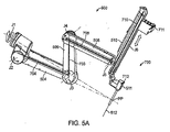
図5A−10に参照して本発明に従った例示的なマニピュレータアームを理解し得よう。上述のように、マニピュレータアームは遠位器具又は手術工具を概ね支持し、ベースに対する器具の動作をもたらす。(典型的には外科助手の助けを受けて)異なるエンドエフェクタを有する多数の異なる器具を外科手術中に各マニピュレータに順次的に取り付け得るので、好ましくは遠位器具ホルダが非取付器具又は工具の素早い取外し又は交換を可能にする。図4を参照して理解され得るように、マニピュレータは患者側カートのベースに近位的に取り付けられる。典型的には、マニピュレータアームは、複数のリンクと、ベースと遠位器具ホルダとの間に延びる関連する継手とを含む。1つの特徴において、所与のエンドエフェクタ位置のために或る範囲の異なる構成を通じてマニピュレータアームの継手を駆動させ得るよう、例示的なマニピュレータは余分の自由度を有する複数の継手を含む。これはここに開示するマニピュレータアームの実施態様のいずれにも当て嵌まり得る。 An exemplary manipulator arm according to the present invention may be understood with reference to FIGS. 5A-10. As described above, the manipulator arm generally supports the distal instrument or surgical tool and provides instrument movement relative to the base. Since a number of different instruments with different end effectors (typically with the help of a surgical assistant) can be attached sequentially to each manipulator during surgery, the distal instrument holder is preferably an unattached instrument or tool Allows for quick removal or replacement. As can be understood with reference to FIG. 4, the manipulator is attached proximally to the base of the patient side cart. Typically, the manipulator arm includes a plurality of links and associated fittings extending between the base and the distal instrument holder. In one aspect, the exemplary manipulator includes a plurality of joints with extra degrees of freedom so that the joints of the manipulator arm can be driven through a range of different configurations for a given end effector position. This may apply to any of the manipulator arm embodiments disclosed herein.
例えば、図5Aに示されるように、特定の実施態様において、例示的なマニピュレータアームは、マニピュレータアームを継手の遠位で継手軸について回転させるために第1の継手軸について回転する近位回転継手J1を含む。一部の実施態様において、回転継手J1はベースに直接的に取り付けられるのに対し、他の実施態様では、回転継手J1を1つ又はそれよりも多くのリンク又は継手に取り付け得る。マニピュレータアームの継手を所与のエンドエフェクタ位置のためのある範囲の異なる構成を通じて駆動させ得るよう、マニピュレータの継手は、組合わせにおいて、余分の自由度を有する。例えば、器具ホルダ510内に支持される(工具512又は器具シャフトが貫通して延びるカニューレのような)遠位部材511が特定の状態を維持する間に図5A−5Dのマニピュレータアームを異なる構成に操作し得る。図5A−5Dのマニピュレータアームはエンドエフェクタの所与の位置又は速度を含み得る。遠位部材511は、典型的には、工具シャフト512が貫通して延びるカニューレであり、器具ホルダ510は、典型的には、カニューレ511を通じて延び最小侵襲的孔を通じて患者の体内に至る前に器具が付着する(円材上を並進する煉瓦状の構造として示される)キャリッジである。
For example, as shown in FIG. 5A, in certain embodiments, an exemplary manipulator arm rotates with a first rotational joint to rotate about the first joint axis to rotate the manipulator arm about the joint axis distal to the joint. Includes J1. In some embodiments, rotary joint J1 is attached directly to the base, while in other embodiments, rotary joint J1 can be attached to one or more links or joints. The manipulator joints have an extra degree of freedom in combination so that the manipulator arm joints can be driven through a range of different configurations for a given end effector position. For example, the manipulator arm of FIGS. 5A-5D may be configured differently while a distal member 511 (such as a
図5A−5D中に例示されるようなリンクを接続する継手の回転の軸と共に図5A−5Dのマニピュレータアーム500の個々のリンクを記載すると、第1のリンク504が旋回継手J2から遠位に延び、旋回継手J2はその継手軸について旋回し且つ回転継手J1に結合され、回転継手J1はその継手軸について回転する。継手の残余の多くを図5Aに示されるようなそれらの関連する近位軸によって特定し得る。例えば、リンク504の遠位端が、旋回継手J3で第2のリンク506の近位端に結合され、旋回継手J3は、その継手軸について旋回する。第3のリンク508の近位端が、旋回継手J4で第2のリンク506の遠位端に結合され、旋回継手J4は、図示のように、その軸について旋回する。第3のリンク508の遠位端は、旋回継手J5で器具ホルダ510に結合される。マニピュレータの幅wの減少をもたらし且つマニピュレータ組立体の操作中のマニピュレータの一部の周りの隙間を改良するために、リンクが図5Dに示されるように互いに隣り合って位置付けられるときにリンクが「積み重ねられて」見えるよう、継手J2,J3,J4,J5の各々の旋回軸を実質的に平行に構成し得る。一部の実施態様において、器具ホルダは、最小侵襲的孔を通じる器具の軸方向動作を促進させ且つ器具が滑動可能に挿入されるカニューレへの器具ホルダの取付けを容易化する、プリズム状の継手J6のような追加的な継手も含む。
Describing the individual links of the
カニューレ511は、器具ホルダ510の遠位に追加的な自由度を含み得る。マニピュレータのモータによって、器具の自由度の作動を駆動させ得る。代替的な実施態様は、器具上にあるものとしてここに示す1つ又はそれよりも多くの継手が代わりにインターフェース上にあるように或いはその逆であるように、迅速に取り外し可能な器具ホルダ/器具インターフェースで、支持するマニピュレータ構造から器具を分離する。一部の実施態様において、カニューレ511は、工具のシャフトが最小侵襲的孔に隣接して旋回する遠隔中心RC又は工具中心の挿入地点の付近又は近位に、回転継手J7(図示せず)を含む。器具の遠位手首部が、器具手首部で1つ又はそれよりも多くの継手の器具継手軸についてカニューレ511を通じるエンドエフェクタの旋回運動を可能にする。エンドエフェクタ場所及び向きと無関係に、エンドエフェクタジョー素子の間の角度を制御し得る。
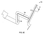
特定の実施態様では、隣接するマニピュレータアームの基準幾何学的構成の間の相対的な状態を決定することによって、アーム間の衝突が今にも起こりそうであり得るときをシステムのプロセッサが決定し得るよう、システムは各マニピュレータアームの位置又は状態に対応する所定の基準幾何学的構成を用いる。図5Aに示されるように、「回避基準幾何学的構成」とも時折呼ぶ基準幾何学的構成700は、対応するラインセグメント704,706,708,701,711を含み得る。各ラインセグメントは、物理的なマニピュレータアーム500のリンクに対応する。「基準幾何学的構成」自体はプロセッサによって定められ(或いは前もって定められ且つ/或いは使用者によって入力され)、マニピュレータの構成部品が手術空間を通じて移動するときに、典型的には継手センサを用いて、その状態はプロセッサによって決定され且つ追跡される。図5Aに示されるラインセグメントは例示的な目的のためであり、基準幾何学的構成がマニピュレータアームに関する構成部品又は機能にどのように対応するかを表示し、且つアーム間の衝突を避けるために本発明に従ってプロセッサによって基準幾何学的構成をどのように定め且つ利用し得るかにおける変形を例示する。基準幾何学的構成は、マニピュレータアームに関連する突起又は機能に対応する地点又はラインセグメントを更に含み得る。例えば、ラインセグメント711は、円材リンク710に移動可能に取り付けられるキャリッジの突出縁に対応し、ラインセグメント712は、カニューレ511を通じて延びる器具のベースの突出縁に対応する。ここに記載するように、図5Eに示されるような、第1のマニピュレータの構成部品に対応する所定の基準幾何学的ラインセグメントを「第1の基準幾何学的構成」と集合的に呼び、図5Eは、基準幾何学的構成700を、マニピュレータアーム500の様々の構成部品に対応する網羅的なラインセグメント706,708,710,711,712として描写する。
In certain embodiments, by determining the relative state between the reference geometry of adjacent manipulator arms, the system processor can determine when a collision between the arms is likely to occur. The system uses a predetermined reference geometry corresponding to the position or state of each manipulator arm. As shown in FIG. 5A, a
図6A−6Cは、本発明に従って、上記のような、第1及び第2のマニピュレータの相互作用並びに第1及び第2の回避基準幾何学的構成の例示的な使用を例示している。図6Aにおけるシステムは、第1のマニピュレータ500と、第2のマニピュレータ500’とを含み、各々のマニピュレータは、所与のエンドエフェクタ位置のためのある範囲の構成を有する運動学的に接合するリンクの同一の組立体を有するが、様々の他のマニピュレータを用い得ること並びに同じシステム内で異なる種類のマニピュレータを組み合わせ得ることが理解されよう。1つの特徴において、システムは、基準幾何学的構成700のラインセグメントと基準幾何学的構成700’のラインセグメントとの間に仮想的な力を適用することによって、マニピュレータの一方又は両方の回避動作を計算する。プロセッサは仮想的な力を用いて、一対の相互作用する素子を互いに離れる方向に移動させるのに必要とされる動作をもたらす継手力を計算する。一部の実施態様において、システムは、相互作用する素子の間に延びる回避ベクトルに沿って上記の基準幾何学的構成を用いて、隣接するマニピュレータの相互作用する素子の間の「反発力」を計算し得る。マニピュレータアームの三次元作業空間内で相対的な状態、回避ベクトル、及び反発力を計算し、次に、継手空間内に変換し得る。次に、継手空間内のマニピュレータアームの動作は、マニピュレータ構成自体に対応する、基準幾何学的構成間の分離を増大させるよう、零空間内の回避動作を決定するために、ヤコビヤンの零空間上に投影されると同時に、マニピュレータの遠位部分の所望の位置を維持する。しばしば、その力は、各マニピュレータの基準幾何学的構成の間の相対的な状態又は距離、最小又は最大距離、或いは所望の距離の関数であり得る(例えば、f(d>d_max)=0、f’(d)<0)(注:f’は、fの微分)。零空間内の回避動作を計算するために、零空間係数を得るために基準幾何学的構成の相互作用する素子の間の計算される反発力の使用を用い得る。零空間係数及び零空間係数を用いて回避動作を計算することを以下により詳細に記載する。
FIGS. 6A-6C illustrate exemplary use of first and second manipulator interactions and first and second avoidance reference geometries, as described above, in accordance with the present invention. The system in FIG. 6A includes a
例示的な実施態様において、システムは、潜在的に相互作用し或いは衝突し得る隣接するマニピュレータから最も近接する対の素子(しばしば「相互作用素子」と呼ぶ)を少なくとも決定する。各マニピュレータから1つの一対の相互作用素子は、重なり合う運動の範囲を有する如何なる対の素子をも含み得る。例えば、図6Aにおいて、1つの相互作用する素子対は711及び711’であるのに対し、他の相互作用する素子対は710及び706’である。一部の実施態様において、システムは特定の分離距離内で相互作用素子を考察するに過ぎない。相互作用する素子対の間の距離(d)が、基準幾何学的構成711及び711’が対応する相互作用素子の間の距離(d)のような、所望未満であるという決定に応答して、プロセッサは、相互作用素子の間の距離を増大させるために、一方又は両方のマニピュレータの回避動作を計算する。他の実施態様では、より効率的な動作をもたらすために或いは動作中に他の相互作用素子対の間の適切な距離を維持するために、回避動作の計算は、710及び706’の間の距離d’のような、他の対の相互作用素子の間の距離を用いて得られる力も含み得る。特定の実施態様において、回避動作は、特定される相互作用素子の間に延びるベクトルに沿う反発力を決定することによって、或いはマニピュレータの作業空間内に仮想的な力を適用し且つ継手空間内の回避動作を計算するためにこの形態を使用することによって計算される。
In an exemplary embodiment, the system determines at least the closest pair of elements (often referred to as “interactive elements”) from adjacent manipulators that can potentially interact or collide. A pair of interacting elements from each manipulator can include any pair of elements having overlapping ranges of motion. For example, in FIG. 6A, one interacting element pair is 711 and 711 ', while the other interacting element pair is 710 and 706'. In some embodiments, the system only considers interactive elements within a specific separation distance. In response to a determination that the distance (d) between the interacting element pairs is less than desired, such as the distance (d) between the reference
一部の実施態様において、回避動作は、計算される回避動作に従って上記計算において用いられる対の1つのマニピュレータの継手を駆動させるために計算される。他の実施態様では、それらの継手が他の計算される動作をもたらすために駆動させられるか否かに拘わらず、マニピュレータのもう1つの特定の継手を駆動させるために、回避動作を計算し得る。加えて、使用者によって命令されるマニピュレータアームの移動動作を実施するときに駆動させられない継手のような、マニピュレータアームの1つ又はそれよりも多くの特定の継手を駆動させるためにも、回避動作を計算し得る。 In some embodiments, the avoidance action is calculated to drive a pair of manipulator joints used in the calculation according to the calculated avoidance action. In other embodiments, avoidance actions may be calculated to drive another particular joint of the manipulator, regardless of whether those joints are driven to cause other calculated actions. . In addition, to avoid driving one or more specific joints of the manipulator arm, such as a joint that is not driven when performing the manipulator arm movement movement commanded by the user The motion can be calculated.
図6Aの実施態様では、距離(d)が所望未満であるという決定に応答して、プロセッサは第2のマニピュレータ500’の計算される回避動作を決定し、基準幾何学的構成711及び711’の間の距離(d)を増大させる。図6Aに示されるように、マニピュレータアームは、各々、それぞれのアームを継手の軸について旋回させる近位の回転継手J1によって支持される。図6B−6Cに示されるように、一方又は両方のアームにおいて継手の組み合わせを用いる一方又は両方のマニピュレータアームの動作は、それぞれ、エンドエフェクタの状態及びその遠隔中心RCを変更させずに、アームの上方部分を移動させ得る。図6Bにおいて、最も近い位置は、ある距離(d1)だけ離れるようにシステムによって決定される。この決定に応答して(或いはここに記載する方法のいずれかに従って)、システムは一方又は両方のアームの1つ又はそれよりも多くの継手を駆動して、各アームの把持でエンドエフェクタの状態を変更せずに(図6Cにd2として示される)最も近い地点の間の距離を増大させる。よって、システムは、ヤコビアンの零空間内で計算される動作に従って一対のマニピュレータのうちの一方の少なくとも第1の継手を駆動することによって、衝突を回避する。一部の実施態様において、少なくとも第1の近位継手を駆動することは回避動作をもたらすと同時に、マニピュレータの遠位部分(エンドエフェクタ)の再構成を最小限化するが、マニピュレータアームのより遠位部分の1つ又はそれよりも多くの継手を駆動するよう、類似の回避動作を計算し得る。他の特徴では、変位動作を実施するときにそのような継手が駆動されるか否かに拘わらず、ここに記載する継手のいずれかを移動させる回避動作を計算するように、或いはマニピュレータの状態又は特定の構成に基づき階層に従った継手の駆動を含めるように、システムを構成し得る。
In the embodiment of FIG. 6A, in response to the determination that the distance (d) is less than desired, the processor determines the calculated avoidance action of the
特定の実施態様によれば、しばしばマニピュレータアーム間の「最も近い地点」を決定することを含む多数の異なる方法に従って回避動作を計算し得る。継手センサを介した既知のマニピュレータ位置又は状態に基づく計算を用いて最も近い地点を決定し得るし、或いは外部センサ、ビデオセンサ、ソナーセンサ、容量センサ、又はタッチセンサ、及び同種のもののような、他の適切な手段を用いて近似させ得る。実施態様は局所的なアーム間の接近及び/又は衝突を感知し得る被駆動リンク又はスレーブに取り付けられる近接センサも用い得る。 According to certain embodiments, avoidance actions may be calculated according to a number of different methods, often including determining the “closest point” between manipulator arms. The closest point can be determined using calculations based on known manipulator positions or conditions via joint sensors, or others such as external sensors, video sensors, sonar sensors, capacitive sensors or touch sensors, and the like Can be approximated using any suitable means. Embodiments may also use proximity sensors attached to driven links or slaves that can sense proximity and / or collision between local arms.
特定の実施態様において、プロセッサは各基準幾何学的構成のラインセグメント上の最も近い地点を決定する。仮想的な反発力を適用した後、プロセッサは、次に、第1及び第2のマニピュレータの間の反発力を計算する。1つの特徴では、隣接するマニピュレータアーム上の交差するラインセグメントが互いに反発するよう、各マニピュレータアームの基準幾何学的構成を「局所的ラインセグメント」と定め得る。他の特徴では、局所的ラインセグメントのみが仮想的な力によって反発させられるよう、一方のマニピュレータの基準幾何学的構成を「局所的ラインセグメント」として定め、他方を「障害ラインセグメント」として定め得る。この特徴は、マニピュレータアームの一方のみ又は一部のみのために回避動作を計算することによって、システムが衝突を回避することを可能にし、それによって、不要な動作又は過剰に複雑な回避動作を防止する。例えば、仮想的な力を各基準幾何学的構成のラインセグメントの間に適用し得るが、「局所的ラインセグメント」の動作のみが計算される。他の実施態様において、プロセッサは、仮想的な力を適用することから得られる計算される力を、回避動作に従って移動させられるべきマニピュレータアームの継手速度に変換し、次に、それは零空間に投影される。これは、所望のエンドエフェクタを維持すると同時にアーム間の衝突を避けるために、回避動作がヤコビアンの零空間内のマニピュレータの継手及び/又はリンクを拡張する仮想的な力を用いて計算されることを可能にする。 In certain embodiments, the processor determines the closest point on the line segment of each reference geometry. After applying the virtual repulsion force, the processor then calculates the repulsion force between the first and second manipulators. In one feature, the reference geometry of each manipulator arm may be defined as a “local line segment” so that intersecting line segments on adjacent manipulator arms repel each other. In other features, the reference geometry of one manipulator can be defined as a "local line segment" and the other as a "failure line segment" so that only the local line segment is repelled by virtual forces . This feature allows the system to avoid collisions by calculating avoidance actions for only one or part of the manipulator arm, thereby preventing unnecessary or overly complex avoidance actions To do. For example, a virtual force may be applied between each reference geometry line segment, but only the “local line segment” motion is calculated. In another embodiment, the processor converts the calculated force resulting from applying the virtual force into the joint speed of the manipulator arm to be moved according to the avoidance action, which is then projected to the null space. Is done. This is calculated using virtual forces that expand manipulator joints and / or links in the Jacobian null space to maintain the desired end effector while avoiding collisions between arms. Enable.
例示的な実施態様において、プロセッサは、しばしばマニピュレータアームの作業空間内の計算を用いて、各マニピュレータアームから少なくとも一対の基準幾何学的構成ラインセグメント、典型的には、最も近い対のラインセグメントの間の距離を決定する。特定の最大除外距離(exclusion distance)よりも近いラインセグメント対のために、最も近い地点が特定される。次に、プロセッサは仮想的な反発ベクトルを適用し、その強さは距離に反比例し、次に、それは継手空間内に変換され、その対のラインセグメントの間の十分な隙間を維持するよう零空間内の移動を計算するために零空間上に投影される。プロセッサは上記プロセスを1つよりも多くのラインセグメント対に行い得る。そのような実施態様では、全てのラインセグメント対からの反発ベクトルの組合わせ結果を最終的な一連の零空間係数(α)に積分し、次に、計算される回避動作を実施するために、最終的な一連の零空間係数(α)を継手コントローラによって用い得る。零空間内の移動を実施するための零空間係数の使用を以下に更に詳細に記載する。 In an exemplary embodiment, the processor often uses computations in the manipulator arm workspace to at least one pair of reference geometric configuration line segments, typically the closest pair of line segments, from each manipulator arm. Determine the distance between. For line segment pairs that are closer than a certain maximum exclusion distance, the closest point is identified. The processor then applies a virtual repulsion vector whose strength is inversely proportional to the distance, which is then transformed into the joint space and zeroed to maintain sufficient clearance between the pair of line segments. Projected onto the null space to calculate movement in space. The processor may perform the above process for more than one line segment pair. In such an embodiment, to combine the repulsion vector combination results from all line segment pairs into a final series of null space coefficients (α) and then perform the calculated avoidance action: The final series of null space coefficients (α) can be used by the joint controller. The use of null space coefficients to perform movement in null space is described in further detail below.
他の例示的な実施態様では、マニピュレータアームの各対のために、プロセッサは、上述のように、各素子に対応する基準幾何学的構成を用いて潜在的に互いに接触し或いは衝突し得る一対の素子又は構成部品を先ず決定する。対応する基準幾何学的構成を用いることによって、次に、システムは、典型的には最大除外距離内の、各対の最も近い素子、多数の相互作用対、又は全ての素子対の効果の重み付け合計を決定する。回避動作を計算するために、プロセッサは、概ね、相互作用素子の各対上の最も近い地点を先ず決定し、素子を互いから離れる方向に「押す」ために用い得る回避ベクトルを計算する。素子を互いから反発させる方向における速度を命令された上述のような仮想的な力を生成することによって、或いは様々の他の方法によって、回避ベクトルを計算し得る。次に、プロセッサは、零空間係数を得るために、基準幾何学的構成の最も近い地点で素子を互いから離れる方向に反発させるのに必要とされる力を零空間ベクトル内でマッピングし、次に、零空間係数は、マニピュレータの零空間内の回避動作を計算するために用いられる。 In another exemplary embodiment, for each pair of manipulator arms, the processor can potentially contact or collide with each other using a reference geometry corresponding to each element, as described above. First, the elements or components are determined. By using the corresponding reference geometry, the system then weights the effects of each pair of closest elements, multiple interaction pairs, or all element pairs, typically within a maximum exclusion distance. Determine the total. To calculate the avoidance action, the processor generally determines the closest point on each pair of interacting elements first and calculates an avoidance vector that can be used to "push" the elements away from each other. The avoidance vector may be calculated by generating a virtual force as described above, commanded for velocity in the direction of repelling the elements from each other, or by various other methods. The processor then maps the forces required to repel the elements away from each other at the closest point of the reference geometry in the null space vector to obtain the null space coefficient, and In addition, the null space coefficient is used to calculate the avoidance action in the null space of the manipulator.
1つのアプローチにおいて、プロセッサはマニピュレータアームの作業空間内の回避ベクトルを計算し、回避ベクトルを継手速度空間内に変換し、次に、回避動作を得るために、その結果を用いて、ベクトルを零空間上に投影する。最も近い地点の間の反発又は回避ベクトルを計算し、作業空間内で、回避ベクトルをマニピュレータアームの「最も近い」地点の運動にマッピングし、次に、最も近い地点を互いから離れる方向に移動させる所望の向き及び大きさをもたらす零空間係数(α)を決定するように、プロセッサを構成し得る。隣接するマニピュレータアーム上の様々の地点又は機能の間で多数の相互作用地点が用いられるならば、各相互作用機能からの回避ベクトルに関連付けられる結果として得られる零空間係数を加法を通じて組み合わせ得る。 In one approach, the processor calculates an avoidance vector in the work space of the manipulator arm, transforms the avoidance vector into the joint velocity space, and then uses the result to obtain a zero to obtain an avoidance action. Project onto space. Calculate the repulsion or avoidance vector between the closest points, map the avoidance vector to the “closest” point movement of the manipulator arm in the workspace, and then move the closest points away from each other The processor may be configured to determine a null space coefficient (α) that yields the desired orientation and magnitude. If multiple interaction points are used between various points or functions on adjacent manipulator arms, the resulting null space coefficients associated with the avoidance vectors from each interaction function can be combined through addition.
他のアプローチにおいて、プロセッサは、零空間基底ベクトルを用い、ベクトルを物理的空間内のマニピュレータの回避幾何学的構成の運動に変換し、次に、物理的空間内のこれら及び回避ベクトルを組み合わせて元々の零空間基底ベクトルのための係数にし得る。マニピュレータアーム(例えば、回避幾何学的構成)の最も近い地点の間の反発又は回避ベクトルを計算し、ちょうど記載したように、これらを回避ベクトルと組み合わせるように、プロセッサを構成し得る。マニピュレータアーム上の多数の機能が用いられるならば、少なくとも平方又は他の方法論を用いて、結果として得られる継手速度ベクトル又は零空間係数を組み合わせ得る。 In another approach, the processor uses a null-space basis vector to convert the vector into motion of the manipulator avoidance geometry in physical space, and then combine these and avoidance vectors in physical space. It can be a coefficient for the original null space basis vector. The processor may be configured to calculate repulsion or avoidance vectors between the closest points of the manipulator arm (eg, avoidance geometry) and combine them with avoidance vectors as just described. If multiple functions on the manipulator arm are used, the resulting joint velocity vector or null space coefficient can be combined using at least square or other methodologies.
第1のアプローチにおいて、高い電位がマニピュレータアームの間のより短い距離を表し、より低い電位がマニピュレータアームの間のより長い距離を表すように、回避動作は継手空間内に電位場を生成することによって決定される。次に、電位場の負の勾配を好ましくは可能な限り最大の程度まで下に降下させるよう、零空間係数が選択される。第2のアプローチにおいて、システムは零空間基底ベクトルを決定し、零空間基底ベクトルを作業空間内の回避幾何学的構成の結果として得られる運動にマッピングし、次に、各基底ベクトルのための零空間係数を選択することは、マニピュレータアームの回避幾何学的構成の間の距離を増大させ、それにより、マニピュレータアーム上の最も近い地点の間の距離を増大させる。 In the first approach, the avoidance action generates a potential field in the joint space so that a high potential represents a shorter distance between the manipulator arms and a lower potential represents a longer distance between the manipulator arms. Determined by. Next, a null space coefficient is selected to lower the negative slope of the potential field, preferably down to the maximum extent possible. In the second approach, the system determines a null space basis vector, maps the null space basis vector to the resulting motion in the workspace, and then zeros for each basis vector. Selecting a spatial coefficient increases the distance between the avoidance geometry of the manipulator arm, thereby increasing the distance between the nearest points on the manipulator arm.
上述のように、如何なる数の異なる種類の継手をも含めるように、或いは代替的に、マニピュレータアームの特定の継手を駆動するのを避けるために、回避動作を計算し得る。本発明に従って異なる角度において用い得る追加的な継手を図7−10に示し、以下に更に記載する。 As mentioned above, avoidance actions may be calculated to include any number of different types of joints, or alternatively to avoid driving a particular joint of a manipulator arm. Additional joints that can be used at different angles in accordance with the present invention are shown in FIGS. 7-10 and are further described below.
図7に示するマニピュレータアームでは、継手J1,J2,J3,J4,J5の様々の組み合わせを駆動することを含むよう回避動作を計算し得(描写の実施態様において、継手J3,J4,J5は平行四辺形の配置において構成され、従って、一体的に移動し、それらの間に単一の状態を有する)、或いは代替的に継手J6並びに零空間内に所要のマニピュレータアームをもたらす任意の他の継手を駆動するように回避動作を計算し得る。器具ホルダ510をマニピュレータアーム508の遠位リンクに結合する継手として図7に例示するマニピュレータアームの継手J6を任意的に用い得る。継手J6は器具ホルダ510が継手J6の軸について捩れ或いは回転するのを可能にし、軸は典型的には遠隔中心又は挿入地点を通過する。理想的には、継手軸はアーム上に遠位に配置され、従って、挿入軸の向きを移動させるのに特に最適である。この余分の自由度の追加は、マニピュレータが任意の単一の器具先端位置のために複数の位置を取ることを可能にし、それにより、器具先端が外科医の命令に従うと同時に、隣接するマニピュレータアーム又は他の障害物との衝突を回避するのを可能にする。取り付けられる手術器具のエンドエフェクタを第1の軸(例えば、縦揺れ軸)の周りで関節動作させ、エンドエフェクタを第1の軸に対して垂直な第2の軸(例えば、偏揺れ軸)の周りで関節動作させるように、マニピュレータアームを構成し得る。継手J6の継手軸、J1の偏揺れ軸、及びカニューレ511の挿入軸の関係は、図8に示されている。
In the manipulator arm shown in FIG. 7, avoidance actions can be calculated to include driving various combinations of joints J1, J2, J3, J4, J5 (in the depicted embodiment, joints J3, J4, J5 are Configured in a parallelogram arrangement, thus moving together and having a single state between them), or alternatively any other joint J6 and any other that provides the required manipulator arm in the null space The avoidance action can be calculated to drive the joint. The joint J6 of the manipulator arm illustrated in FIG. 7 may optionally be used as a joint for coupling the
図7も、回転継手の継手軸についてマニピュレータアームを回転させる近位の回転継手J1を有するマニピュレータを例示している。継手J1は、次の連続的な継手を所定の距離又は角度だけ偏らせるリンク501を含む。典型的には、継手J1の継手軸は、図7の各々において示されるように、工具先端の挿入地点又は遠隔中心RCと整列させられる。例示的な実施態様では、体壁での運動を防止し、従って、手術中に移動させられ得るよう、継手J1の継手軸は、マニピュレータアームにおける各々の他の回転継手軸と同様に、遠隔中心を通過する。継手軸はアームの近位部分に結合させられるので、アームの背の位置及び向きを変更するために継手軸を用い得る。一般的に、これのような余分な軸は、器具先端が外科医の命令に従うと同時に、他のアーム又は患者の解剖学的構造と衝突することを回避することを可能にする。 FIG. 7 also illustrates a manipulator having a proximal rotary joint J1 that rotates the manipulator arm about the joint axis of the rotary joint. The joint J1 includes a link 501 that biases the next continuous joint by a predetermined distance or angle. Typically, the joint axis of joint J1 is aligned with the tool tip insertion point or remote center RC, as shown in each of FIGS. In an exemplary embodiment, the joint axis of joint J1, like each other rotary joint axis in the manipulator arm, is remote centered so as to prevent movement on the body wall and thus be moved during surgery. Pass through. Since the joint shaft is coupled to the proximal portion of the arm, the joint shaft can be used to change the position and orientation of the back of the arm. In general, an extra axis such as this allows the instrument tip to follow the surgeon's instructions while avoiding colliding with other arms or the patient's anatomy.
図9−10は、例示的なマニピュレータアームと共に使用するための他の種類の余分な継手、ある軸についてマニピュレータアームを回転させる近位継手を例示している。一部の実施態様において、マニピュレータアームを支持する第1の継手J1は、マニピュレータアームの運動の範囲を増大させるよう曲線経路に沿って並進し、マニピュレータアームが減少した操作性を有し得る地域から離れて並進する。この地点は、図9に示すような円形の経路を含み得、或いは図10に示すような半円又は弓形の経路を含み得る。一般的に、そのような実施態様において、継手軸は遠隔中心RCと交差し、工具先端のシャフトは遠隔中心RCについて旋回する。図9に示す実施態様において、継手軸は垂直軸であるのに対し、図10に示す実施態様において、継手軸は水平である。 FIGS. 9-10 illustrate another type of extra joint for use with the exemplary manipulator arm, a proximal joint that rotates the manipulator arm about an axis. In some embodiments, the first joint J1 that supports the manipulator arm translates along a curved path to increase the range of motion of the manipulator arm, from an area where the manipulator arm may have reduced operability. Translate away. This point may include a circular path as shown in FIG. 9, or may include a semi-circular or arcuate path as shown in FIG. Generally, in such an embodiment, the joint axis intersects the remote center RC and the tool tip shaft pivots about the remote center RC. In the embodiment shown in FIG. 9, the joint axis is a vertical axis, whereas in the embodiment shown in FIG. 10, the joint axis is horizontal.
例示的な実施態様において、マニピュレータの継手動作は、システムのモータを用いてコントローラによって1つ又はそれよりも多くの継手を駆動することによって制御され、継手はコントローラのプロセッサによって計算された協調的な関節動作に従って駆動される。数学的に、コントローラはベクトル及び/又はマトリクスを用いて継手命令の少なくとも一部を遂行し得、それらの一部は継手の構成または速度に対応する素子を有し得る。プロセッサに利用可能な代替的な継手構造の範囲を継手空間として概念化し得る。継手空間は、例えば、マニピュレータが自由度を有するのと同じ次元を有し得、マニピュレータの特定の構成が継手空間内に特定の地点を表し得、各座標はマニピュレータの関連する継手の継手状態に対応する。 In an exemplary embodiment, the joint operation of the manipulator is controlled by driving one or more joints by the controller using the motors of the system, the joints being coordinated as calculated by the controller processor. Driven according to joint movement. Mathematically, the controller may use vectors and / or matrices to perform at least some of the joint instructions, some of which may have elements that correspond to the joint configuration or speed. A range of alternative joint structures available to the processor can be conceptualized as joint space. A joint space may have the same dimensions as a manipulator, for example, with a degree of freedom, a particular configuration of the manipulator may represent a particular point in the joint space, and each coordinate is a joint state of the associated joint of the manipulator. Correspond.
特定の実施態様において、システムはコントローラを含み、コントローラにおいて、デカルト座標空間(以下「デカルト空間」という)内の命令される位置及び速度は入力である。一般的にではあるが、所望のデカルト空間位置を均等な継手空間位置にマッピングする閉形式の関係はなく、デカルト空間速度に対して継手空間速度をマッピングするために運動学的ヤコビアンを用い得るよう、デカルト空間速度と継手空間速度との間の閉形式の関係が概ねある。よって、入力位置と出力位置との間に閉形式のマッピングがないときでさえ、例えば、ヤコビアンに基づくコントローラにおいて、命令される使用者入力からマニピュレータの動作を実施するために、継手の速度のマッピングを反復的に用い得るが、様々のインプレメンテーション(implementations)を用い得る。 In certain embodiments, the system includes a controller, where the commanded position and velocity in a Cartesian coordinate space (hereinafter “Cartesian space”) are inputs. In general, there is no closed-form relationship to map the desired Cartesian space position to the equivalent joint space position, so that the kinematic Jacobian can be used to map the joint space velocity to the Cartesian space velocity. There is generally a closed form relationship between Cartesian space velocity and joint space velocity. Thus, even when there is no closed-form mapping between input and output positions, for example, in a Jacobian-based controller, the joint velocity mapping to perform manipulator actions from commanded user input Can be used iteratively, but various implementations can be used.
例示的な実施態様において、システムはコントローラを含み、コントローラにおいて、ここではデカルト空間として示される作業空間内の機能の命令される位置及び速度は入力である。その機能は、マニピュレータ上の如何なる機能であってよく、或いは制御入力を用いて関節作動させられるべき制御フレームとして使用し得るマニピュレータから離れた機能であってもよい。ここに記載される一部の実施態様において用いられるマニピュレータ上の機能の実施例は、工具先端である。マニピュレータ上の機能の他の実施例は、工具先端上の物理的な機能でなく、ピン又は彩色模様のようなマニピュレータの一部である。マニピュレータから離れた機能の実施例は、工具先端から正に特定の距離及び角度だけ離れた空間内の基準地点である。マニピュレータから離れた機能の他の実施例は、マニピュレータに対するその位置を構築し得る標的組織である。全てのこれらの場合において、エンドエフェクタは、制御入力を用いて関節作動させられるべき仮想の制御フレームと関連付けられる。しかしながら、以下において、「エンドエフェクタ」及び「工具先端」は同義的に用いられる。一般的にであるが、所望のデカルト空間エンドエフェクタ位置を均等な継手空間位置にマッピングする閉形式の関係はなく、デカルト空間エンドエフェクタと継手空間速度との間に概ね閉形式の関係がある。運動学的ヤコビアンは、継手空間位置素子に対するエンドエフェクタのデカルト空間位置素子の偏微分の行列である。このようにして、運動学的ヤコビアンはエンドエフェクタと継手との間の運動学的関係を捕捉する。換言すれば、運動学的ヤコビアンはエンドエフェクタ上で継手運動の効果を捕捉する。以下の関係を用いてデカルト空間エンドエフェクタ速度(dx/dt)に対して継手空間速度(dq/dt)をマッピングするために運動学的ヤコビアン(J)を用い得る。

よって、入力位置と出力位置との間に閉形式のマッピングがないときでさえも、例えば、ヤコビアンに基づくコントローラにおいて、命令される使用者入力からマニピュレータの動作を実施するために、速度のマッピングを反復的に用い得るが、様々のインプレメンテーションも用い得る。一部の実施態様はヤコビアンに基づくコントローラを含むが、一部のインプレメンテーションは、ここに記載する機能のいずれかをもたらすためにヤコビアンにアクセスするように構成し得る様々の種類のコントローラを用い得る。 Thus, even when there is no closed-form mapping between input and output positions, for example, in a Jacobian-based controller, a velocity mapping can be used to perform manipulator operations from commanded user input. Although it can be used iteratively, various implementations can also be used. Some implementations include a Jacobian-based controller, but some implementations use various types of controllers that can be configured to access the Jacobian to provide any of the functions described herein. obtain.
1つのそのようなインプレメンテーションを以下に簡略化された用語において記載する。ヤコビアン(J)を計算するために、命令される継手位置を用いる。各時間ステップ(□t)の間に、所望の動作(dxdes/dt)を行い且つ所望のデカルト空間位置からの蓄積された微分(□x)を矯正するために、デカルト空間速度(dx/dt)を計算する。次に、ヤコビアンの疑似逆(J#)を用いてこのデカルト空間速度を継手空間速度(dq/dt)に変換する。次に、継手空間命令された位置(q)をもたらすよう、結果として得られる継手空間命令された速度を積分する。これらの関係を以下に列挙する。
ヤコビアン(J)の疑似逆は、所望の工具先端動作(そして、一部の場合には、旋回的工具運動の遠隔中心)を継手速度空間内に直接的にマッピングする。使用されるマニピュレータが(最大6までの)工具先端自由度よりも有用な継手軸を有するならば、(そして、工具運動の遠隔中心が使用中であり、マニピュレータが遠隔中心の場所と関連付けられる3つの自由度のために追加的な3つの継手軸を有さなければならないとき)、マニピュレータは余分であると言われる。余分なマニピュレータのヤコビアンは、少なくとも1つの次元を有する「零空間」を含む。この脈絡において、ヤコビアンの「零空間」(N(J))は、工具先端運動を瞬間的に達成しない継手速度の空間であり(そして、遠隔中心が用いられるとき、旋回地点場所の移動はない。「零運動」は、遠隔中心の場所及び/又は工具先端の瞬間的を同様にもたらさない継手位置の組み合わせ、軌跡、又は経路である。(ここに記載する如何なる再構成をも含む)マニピュレータの所望の再構成を達成するために、計算される零空間速度をマニピュレータの制御システム内に組み込む或いは注入することは、上記等式(2)を以下の通り変更する。
等式(4)に従った継手速度は2つの成分を有し、第1の成分は、零垂直空間成分(null-perpendicular-space component)、即ち、所望の工具先端運動をもたらす、(そして、遠隔中心が用いられるときに、所望の遠隔中心運動をもたらす)、「最も純粋な」継手速度(最短のベクトル長)であり、第2の成分は、零空間成分(null-space component)である。等式(2)及び(5)は、零空間成分がないならば、同じ等式が達成されることを示している。等式(6)は、左側の及び一番右側の零空間成分のための従来的な形態で開始し、例示的なシステムにおいて用いられる形態を示し、(Vn)は、零空間のための一組の正規直交基底ベクトルであり、(α)はそれらの基底ベクトルを混合させるための係数である。一部の実施態様では、零空間内の運動を所望に成形し或いは制御するために、αは、例えば、ノブ又は他の制御手段の使用によって、制御パラメータ、変数、又は設定によって決定される。 The joint speed according to equation (4) has two components, the first component provides a null-perpendicular-space component, i.e. the desired tool tip motion (and The desired pure center motion when a remote center is used), the “pure” joint velocity (shortest vector length), and the second component is a null-space component . Equations (2) and (5) show that the same equation is achieved if there is no null space component. Equation (6) starts with the conventional form for the left and rightmost null space components and shows the form used in the exemplary system, where (V n ) is for the null space. It is a set of orthonormal basis vectors, and (α) is a coefficient for mixing the basis vectors. In some embodiments, α is determined by a control parameter, variable, or setting, eg, by use of a knob or other control means, in order to shape or control the movement in the null space as desired.
図11Aは、例示的なマニピュレータアーム内のヤコビアンの零空間とヤコビアンの零垂直空間との間の関係を図式的に例示している。図11Aは、水平軸に沿う零空間及び垂直軸に沿う零垂直空間を示す二次元の概略図であり、2つの軸は互いに直交している。対角線のベクトルは、零空間における速度ベクトル及び零垂直空間における速度ベクトルの合計を表しており、それは上記等式(4)の表現である。 FIG. 11A schematically illustrates the relationship between Jacobian null space and Jacobian null vertical space in an exemplary manipulator arm. FIG. 11A is a two-dimensional schematic diagram showing a zero space along the horizontal axis and a zero vertical space along the vertical axis, the two axes being orthogonal to each other. The diagonal vector represents the sum of the velocity vector in the null space and the velocity vector in the zero vertical space, which is a representation of equation (4) above.
図11Bは、「零運動マニホルド」として示される、四次元継手空間内の零空間と零運動マニホルドとの間の関係を図式的に例示している。各矢印(q1,q2,q3,q4)は、主継手軸を表している。閉塞円弧は、同じエンドエフェクタ状態(例えば、位置)を瞬間的に達成する一組の継手空間位置である零運動マニホルドを表している。円弧上の所与の地点Aのために、零空間はエンドエフェクタの動作を瞬間的にもたらさない継手速度の空間であるので、零空間は地点Aで零運動マニホルドの接線に対して平行である。例示的な実施態様において、回避動作を計算することは、第1及び第2の基準幾何学的構成を用いて決定されるような相互作用素子対間の距離を増大させ、それにより、マニピュレータアーム間の距離を増大させる、零空間係数(α)を生成することを含む。 FIG. 11B schematically illustrates the relationship between the null space and the zero motion manifold in the four-dimensional joint space, denoted as “zero motion manifold”. Each arrow (q1, q2, q3, q4) represents the main joint shaft. A closed arc represents a zero motion manifold, which is a set of joint space positions that instantaneously achieve the same end effector state (eg, position). For a given point A on the arc, the null space is parallel to the tangent of the zero motion manifold at point A because the null space is a joint velocity space that does not cause end effector motion instantaneously. . In an exemplary embodiment, calculating the avoidance action increases the distance between the pair of interacting elements as determined using the first and second reference geometries, thereby providing a manipulator arm Generating a null space coefficient (α) that increases the distance between.
図12−13は、本発明の実施態様に従ってアーム間の衝突を回避するロボット手術システムのマニピュレータ組立体を再構成する方法を例示している。図12は、上記で議論した等式に関連して、患者側カート継手状態を制御する一般的アルゴリズムを実施するのに必要とされる所要ブロックの簡略図を示している。図12の方法によれば、システムは、マニピュレータアームの前方運動学を計算し、次に、等式(1)を用いてdx/dtを計算し、等式(5)を用いてdqprep/dtを計算し、次に、等式(6)を用いてdqnull/dtを計算する。計算したdqprep/dt及びdqnull/dtから、システムは、次に、等式(4)及び(3)を用いてdq/dt及びqをそれぞれ計算し、それにより、コントローラがマニピュレータの回避動作に影響を及ぼしながらエンドエフェクタの所望の命令状態(及び/又は遠隔中心の場所)を維持する動作をもたらす。 12-13 illustrate a method for reconfiguring a manipulator assembly of a robotic surgical system that avoids collisions between arms according to an embodiment of the present invention. FIG. 12 shows a simplified diagram of the required blocks required to implement the general algorithm for controlling patient side cart joint status in connection with the equations discussed above. According to the method of FIG. 12, the system calculates the forward kinematics of the manipulator arm, then calculates dx / dt using equation (1), and dq prep / using equation (5). Calculate dt and then calculate dq null / dt using equation (6). From the calculated dq prep / dt and dq null / dt, the system then calculates dq / dt and q using equations (4) and (3), respectively, so that the controller avoids manipulator avoidance Effects that maintain the desired command state (and / or remote center location) of the end effector.
図13は、システムの例示的な実施態様のブロック図を示している。所望の先端状態をもたらすために使用者によって入力される操作命令に応じて、システムは、継手状態センサを用いて決定されるような現今の継手位置を用いて、適切なヤコビアン、故に、dqprep/dtを計算し、所望の先端状態をもたらす。各マニピュレータアームの基準幾何学的構成の間の距離(d)を決定するためにも、現今の継手位置を用い得る。隣接するアームの相互作用素子上の基準対の基準幾何学的構成の間の距離(d)が臨界的な距離(dmin)未満であるという決定に応じて、システムは、(d)を増大させる継手速度dqnull/dtを決定し、次に、それをdqprep/dtと組み合わせてdq/dtを得て、それに従って、継手はアーム間の衝突を回避すると同時に所望の先端状態をもたらすように駆動させられる。 FIG. 13 shows a block diagram of an exemplary implementation of the system. In response to an operational command entered by the user to produce the desired tip condition, the system uses the current joint position as determined using the joint state sensor to determine the appropriate Jacobian and hence dq prep. / Dt is calculated to produce the desired tip condition. The current joint position can also be used to determine the distance (d) between the reference geometry of each manipulator arm. In response to determining that the distance (d) between the reference geometry of the reference pair on the interacting elements of adjacent arms is less than the critical distance (d min ), the system increases (d) Determine the joint speed to be dq null / dt and then combine it with dq prep / dt to obtain dq / dt, so that the joint avoids collisions between arms and at the same time produces the desired tip condition Driven.
理解の明確性のために一例として例示的な実施態様を詳細に記載したが、様々の適合、変形、及び変更が当業者に明らかであろう。故に、本発明の範囲は専ら付属の請求項によって限定される。 While exemplary embodiments have been described in detail by way of example for clarity of understanding, various adaptations, modifications and changes will be apparent to those skilled in the art. Therefore, the scope of the present invention is limited solely by the appended claims.
Claims (30)
プロセッサとを含み、
各マニピュレータアームは、遠位部分と、近位ベースに結合され且つ前記遠位部分を前記近位ベースに対して無人操作で移動させるために構成される近位部分とを有し、各マニピュレータアームは、前記遠位部分と前記近位ベースとの間に複数の継手を有し、該複数の継手は、各マニピュレータアームの遠位部分状態のために或る範囲の継手状態を可能にするのに十分な自由度を備える継手空間を有し、
前記プロセッサは、操作を実行するように構成され、
前記操作は、前記第1のマニピュレータアームの第1の基準幾何学的構成及び前記第2のマニピュレータアームの第2の基準幾何学的構成を決定することを含み、前記第1及び第2の基準幾何学的構成は、作業空間内で関連付けられるマニピュレータアームと共に移動可能であり、前記第1及び第2の基準幾何学的構成は、重なり合う運動の範囲を有し、
前記操作は、前記作業空間内の前記第1の基準幾何学的構成と前記第2の基準幾何学的構成との間の相対的状態を決定することを含み、
前記操作は、該相対的状態に基づき所望の回避ベクトルを決定することを含み、
前記操作は、前記作業空間内の前記第1及び第2の基準幾何学的構成の間の分離を維持するよう、前記第1及び第2のマニピュレータアームの複数の継手のうちの1つ又はそれよりも多くの継手の回避動作を計算することを含み、該回避動作は、前記第1及び第2のマニピュレータアームの前記継手空間の一方又は両方の内で計算され、前記回避動作は、前記回避動作が前記第1及び第2のマニピュレータアームのそれぞれのマニピュレータアームと関連付けられるヤコビアンの零空間内に制約されるように、前記所望の回避ベクトルに基づき、並びに
前記操作は、前記計算される回避動作に従って前記第1及び第2のマニピュレータアームの複数の継手のうちの前記1つ又はそれよりも多くの継手を駆動させることを含む、
ロボットシステム。 First and second manipulator arms;
Including a processor,
Each manipulator arm has a distal portion and a proximal portion coupled to the proximal base and configured for unattended movement of the distal portion relative to the proximal base, each manipulator arm Has a plurality of joints between the distal portion and the proximal base, the plurality of joints allowing a range of joint states for the distal portion state of each manipulator arm. A joint space with a sufficient degree of freedom,
The processor is configured to perform an operation;
The operation includes determining a second reference geometrical configuration of the first of the first reference geometry and the second manipulator arm of the manipulator arm, the first and second reference A geometric configuration is movable with the associated manipulator arm in the workspace, wherein the first and second reference geometric configurations have overlapping ranges of motion;
The operation includes determining a relative state between the first reference geometry and the second reference geometry in the workspace;
The operation includes determining a desired avoidance vector based on the relative state ;
The operation may include one or more of the joints of the first and second manipulator arms to maintain a separation between the first and second reference geometric configurations in the work space. includes calculating an avoidance operation of a number of joint than the avoidance operation is computed within one or both of the joint space of the first and second manipulator arms, the avoidance operation, the avoidance operation to be constrained to the first and zero space of the Jacobian associated with each manipulator arm of the second manipulator arm,-out based on the desired avoidance vector, and
The operation involves driving the one or more joints than that of the plurality of joints of the first and second manipulator arm according avoidance operation is the calculation,
Robot system.
前記相対的状態を決定することは、前記第2の基準幾何学的構成の前記複数のラインセグメントのうちの第2のラインセグメントに最も近い、前記第1の基準幾何学的構成の前記複数のラインセグメントのうちの第1のラインセグメントを決定することを更に含み、前記第1及び第2のラインセグメントは、前記第1及び第2のマニピュレータアームの最も近い構成に対応し、並びに
前記相対的状態を決定することは、前記第1及び第2のラインセグメントを通じて延びるよう、前記所望の回避ベクトルを計算することを更に含む、
請求項6に記載のロボットシステム。 Each of the first and second reference geometric configurations includes a plurality of line segments, each line segment corresponding to a configuration on the respective manipulator arm;
Determining the relative state is closest to the second line segment of the plurality of line segment in the second reference geometry, wherein the plurality of said first reference geometry Further comprising determining a first line segment of the line segments, wherein the first and second line segments correspond to closest configurations of the first and second manipulator arms , and
Determining the relative state, to extend through the first and second line segments, further comprising calculating the desired avoidance vector,
The robot system according to claim 6.
前記回避動作を計算することが、
前記所望の回避ベクトルの方向において適用されるときに前記第1及び第2の基準幾何学的構成の間の所望の距離を維持するのに十分な前記第1及び第2の基準幾何学的構成の間の反発力を計算すること、及び
前記所望の回避ベクトルに沿って前記第1及び第2のマニピュレータアームの間に適用される前記反発力に応答して前記第1及び第2のマニピュレータアームの複数の継手のうちの前記1つ又はそれよりも多くの継手の動作を計算することを含むように、
更に構成される、
請求項5に記載のロボットシステム。 The processor is
Calculating the avoidance action;
Said first and sufficient said first and second reference geometrical to maintain Nozomu Tokoro distance between the second reference geometry when applied in the direction of the desired avoidance vector calculating the repulsive forces between the structure and the desired avoidance along a vector in response to the repulsive force applied between the first and second manipulator arm said first and second manipulators to include that you calculate the one or operation of a number of joint than that of the plurality of joints of the arm,
Further configured,
The robot system according to claim 5.
前記回避動作を計算することが、
前記所望の回避ベクトルの方向において適用されるときに前記第1及び第2の基準幾何学的構成の間の所望の距離を維持するのに十分な第1及び第2の基準幾何学的構成の間の反発被命令速度を計算することを含み、前記第1及び第2の基準幾何学的構成が、前記第1及び第2のマニピュレータアームの対応する構成についてのラインセグメントを含み、且つ
前記所望の回避ベクトルに沿う前記第1及び第2のマニピュレータアームの前記対応する構成についてのラインセグメントに適用される前記反発被命令速度に応答して前記第1及び第2のマニピュレータアームの複数の継手のうちの前記1つ又はそれよりも多くの継手の動作を計算することを含むように、
更に構成される、
請求項5に記載のロボットシステム。 The processor is
Calculating the avoidance action;
Reference geometry Nozomu Tokoro distance sufficient first and second to maintain the between the first and second reference geometry when applied in the direction of the desired avoidance vector Calculating the repelled command speed between the first and second reference geometrical configurations including line segments for corresponding configurations of the first and second manipulator arms , and A plurality of joints of the first and second manipulator arms in response to the repulsive command speed applied to a line segment for the corresponding configuration of the first and second manipulator arms along a desired avoidance vector said to include one or calculate child behavior of many joint than that of,
Further configured,
The robot system according to claim 5.
前記プロセッサは、マニピュレータアームについての操作を実行するように更に構成され、
前記操作は、前記操作命令に応答して前記それぞれのマニピュレータアームの前記複数の継手の遠位部分変位動作を計算することを含み、前記それぞれのマニピュレータアームの前記複数の継手の前記遠位部分変位動作は、前記継手の動作が前記それぞれのマニピュレータアームの前記ヤコビアンの零垂直空間内に制約されるように計算され、前記零垂直空間は、前記零空間に対して直交し、並びに
前記操作は、前記所望の遠位部分動作をもたらすために前記計算される遠位部分変位動作に従って前記それぞれのマニピュレータアームの前記複数の継手を駆動させることを含む、
請求項1に記載のロボットシステム。 Further comprising a desired input that will receive an operation instruction to move the distal portion of each of the manipulator arms of the first and second manipulator arm at the distal portion operation,
The processor is further configured to perform operations on the manipulator arm;
The operation in response to the operation instruction comprises calculating a distal portion displacement operation of the plurality of joints of the respective manipulator arms, the distal portion displacement of the plurality of joints of the respective manipulator arms operation is calculated so that the operation of the joint is constrained in between zero vertical empty the Jacobian of the respective manipulator arms, the zero vertical space is orthogonal to the null space, and
The operation includes driving the plurality of joints of the respective manipulator arm according distal portion displacement movement which is pre-Symbol calculated to produce the desired distal portion operation,
The robot system according to claim 1.
前記プロセッサは、操作を実行するように更に構成され、
前記操作は、前記1つ又はそれよりも多くの追加的なマニピュレータアーム上の追加的な基準幾何学的構成を決定することを含み、該追加的な基準幾何学的構成は、前記第1及び第2の基準幾何学的構成を重なり合う運動の範囲を有し、
前記操作は、前記作業空間内で重なり合う運動の範囲を有する基準幾何学的構成との間の相対的状態と、前記1つ又はそれよりも多くの追加的なマニピュレータアームの前記追加的な基準幾何学的構成と前記第1又は第2の基準幾何学的構成との間の所望の回避ベクトルとを決定することを含み、
前記操作は、前記1つ又はそれよりも多くの追加的なマニピュレータアーム並びに前記第1及び第2のマニピュレータアームの前記基準幾何学的構成の間の分離を維持するために、前記1つ又はそれよりも多くの追加的なマニピュレータアームの複数の継手のうちの1つ又はそれよりも多くの継手の前記回避動作を計算することを含み、前記回避動作は、前記回避動作がそれぞれのヤコビアンの前記零空間内に制約されるように、それぞれのマニピュレータアームの前記継手空間内で計算され、並びに
前記操作は、該計算される回避動作に従って前記1つ又はそれよりも多くの追加的なマニピュレータアームの前記複数の継手のうちの前記1つ又はそれよりも多くの継手を駆動させることを含む、
請求項1に記載のロボットシステム。 And further including one or more additional manipulator arms, each additional arm including a movable distal portion, a proximal portion coupled to the proximal base, and the distal portion. A plurality of joints between the proximal base and the plurality of joints for the condition of the distal portion of each manipulator arm of the one or more additional manipulator arms or Having joint spaces with sufficient degrees of freedom to allow different ranges of joint conditions,
The processor is further configured to perform an operation;
The operation comprises determining an additional reference geometry before SL on one or more additional manipulator arms than, the additional criteria geometry, the first And a range of motion that overlaps the second reference geometry ,
The operation, the relative state and the additional base geometric of the one or more additional manipulator arms than that between the reference geometry having a range of motion that overlap in the working space and determining the desired avoidance vector between the histological structure and said first or second reference geometry,
The operation is to maintain the separation between the reference geometry of the one or more many additional manipulator arms and the first and second manipulator arms, wherein one or It includes calculating a number of one or the avoidance operation of a number of joint hands than of a plurality of joints additional manipulator arms than the avoidance operation, the avoidance operation of each Jacobian as constrained to the zero space, it is calculated within the joint space of each manipulator arm, and
The operation includes driving said one or more joints than those of the plurality of joints of the one or more additional manipulator arms than accordingly avoiding action to be said calculated,
The robot system according to claim 1.
前記遠位部分は、手術エンドエフェクタに対して遠位に延びる細長いシャフトを有する手術器具を含み或いはそれを解放可能に支持するように構成され、
前記手術器具の前記シャフトは、手術中に前記マニピュレータアームの遠隔中心について旋回し、
前記第1及び第2のマニピュレータアームの前記複数の継手のうちの前記1つ又はそれよりも多くの継手の前記回避動作は、前記第1及び第2のマニピュレータアームの前記複数の継手のうちの前記1つ又はそれよりも多くの継手の前記駆動中に前記マニピュレータアームの前記遠隔中心の位置を維持するように計算される、
請求項1に記載のロボットシステム。 For each manipulator arm of the first and second manipulator arms,
Before SL distal portion is configured to releasably supporting includes or it surgical instrument having an elongated shaft extending distally relative to the surgical end-effector,
The shaft of the surgical instrument pivots about a remote center of the manipulator arm during surgery,
The avoidance action of the one or more joints of the plurality of joints of the first and second manipulator arms is determined from the plurality of joints of the first and second manipulator arms . is calculated to maintain the position of the remote center of the manipulator arm during the driving of the one or more joints Rather,
The robot system according to claim 1.
前記マニピュレータアームは、中間部分と各中間部分の遠位端にあるエンドエフェクタとを有する工具を支持するように構成され、前記中間部分は、前記近位部分の遠位に挿入軸に沿って延び、
前記マニピュレータアームの前記複数の継手のうちの少なくとも幾つかの継手は、作業部位での前記エンドエフェクタの動作を促進するために、前記マニピュレータアームの前記遠位部分が前記挿入軸に配置される遠隔中心について旋回するよう、前記近位ベースに対する前記遠位部分の動作を機械的に制約し、前記作業部位は、挿入開口を通じてアクセスされる、
請求項13に記載のロボットシステム。 For each manipulator arm of the first and second manipulator arms,
The manipulator arm is configured to support a tool having an intermediate portion and an end effector at the distal end of each intermediate portion, the intermediate portion extending along an insertion axis distal to the proximal portion. ,
At least some of the joints of the plurality of joints of the manipulator arm, in order to facilitate the operation of the end effector at the worksite, the distal portion of the front Kemah two Manipulator regulator arm is arranged in the insertion shaft Mechanically constraining the movement of the distal portion relative to the proximal base to pivot about a remote center, wherein the work site is accessed through an insertion opening;
The robot system according to claim 13.
前記マニピュレータアームの複数の継手が、前記マニピュレータアームの前記近位部分の遠位に配置され且つ前記遠位部分の近位に配置される遠隔球状中心継手を含み、
該遠隔球状中心継手は、前記遠隔球状中心継手の関節が前記マニピュレータアームの前記遠位部分を第1、第2、及び第3の遠隔中心軸について旋回させるよう機械的に制約され、
前記第1、第2、及び第3の遠隔中心軸は、その遠隔中心と交差する、
請求項16に記載のロボットシステム。 For each manipulator arm of the first and second manipulator arms,
A plurality of joints of the manipulator arm comprises a remote spherical center joint disposed proximal of the distal to the disposed and the distal portion of the proximal portion of the front Kemah two Manipulator regulator arm,
The remote spherical center joint, wherein the distal portion of the first remote spherical center joints before KOR two Manipulator regulator arm of the joint, is constrained second, and third mechanically so as to pivot about a remote center axis,
The first, second and third remote central axes intersect the remote center;
The robot system according to claim 16.
前記マニピュレータアームの前記近位部分は、前記近位部分が移動するときに、前記遠隔中心の遠位部分が前記マニピュレータアームの前記遠隔中心について旋回するよう、前記近位ベースに対して機械的に制約される、
請求項16に記載のロボットシステム。 For each manipulator arm of the first and second manipulator arms,
The proximal portion of the manipulator arm, when the proximal portion is moved, so that the distal portion of the remote center to pivot about the remote center of the manipulator arm, mechanically relative to the proximal base Constrained,
The robot system according to claim 16.
前記マニピュレータアームの前記複数の継手は、前記マニピュレータアームの遠位部分の近くに回転継手を含み、該回転継手は、前記挿入軸を前記遠位の回転継手の軸について旋回させ、前記それぞれの継手の前記軸は、前記遠隔中心を通じて延びる、
請求項16に記載のロボットシステム。 For each manipulator arm of the first and second manipulator arms,
The plurality of joints of the manipulator arm include a rotary joint near a distal portion of the manipulator arm, the rotary joint pivoting the insertion axis about the axis of the distal rotary joint, the respective joints The axis extends through the remote center,
The robot system according to claim 16.
前記マニピュレータアームの第1の継手が、前記近位部分を前記近位ベースに結合させ、前記第1の継手は、前記マニピュレータアームの前記遠位部分を支持する回転継手を含むことで、該回転継手の継手動作は、前記マニピュレータアームの前記遠位部分を前記回転継手の旋回軸について旋回させ、前記旋回軸は、前記マニピュレータアームの前記挿入軸が前記マニピュレータアームの前記遠隔中心に向かって方向付けられる遠位に先細る円錐に沿って移動するよう、前記回転継手から前記マニピュレータアームの前記遠隔中心を通じて延びる、請求項16に記載のロボットシステム。 For each manipulator arm of the first and second manipulator arms,
First joint of the manipulator arm, the proximal portion is coupled to the proximal base, the first joint, that includes a rotary joint for supporting the distal portion of the manipulator arm, the rotary joint operation of the joint, the distal portion of the front Kemah two manipulator regulator arm to pivot about the pivot axis of the rotary joint, the pivot axis, the insertion axis of the manipulator arm toward said remote center of the manipulator arm to move along a cone tapering distally directed, it extends through front Kito隔中center of the manipulator arm from the rotary joint, a robot system according to claim 16.
前記プロセッサは、前記第1及び第2のマニピュレータアームの間の衝突を抑制しながら、前記計算される再構成動作をもたらすために、前記相対的状態が、所望未満である前記第1及び第2のマニピュレータアームの幾何学的構成の間の分離に応答するときに、前記複数の継手を、前記計算される回避動作と同時に前記計算される再構成動作に従って駆動させるように、構成される、
請求項24に記載のロボットシステム。 Wherein the processor one or avoidance operation which is the calculation of the number of joint than the one of the plurality of joints of the first and second manipulator arms, the first and second manipulator arms with the rebuild operation is the calculation of the plurality of joints, as in the zero space of the Jacobian associated with the first and second manipulator arms, reconstruction of the plurality of joints in response to the reconfiguration instruction operated to calculate is further configured, the processor, during the reconstruction operation, in order to maintain a desired state of said distal portion, said plurality of said first and second manipulator arms to the one or in the avoidance operation which is the calculation of the number of joints than of joint, the first and second manipulators a according rebuild operation is the calculated As driving the plurality of joints of arm, it is constructed,
Wherein the processor, while suppressing a collision between the first and second manipulator arm in order to provide a reconstruction operation that is the calculated, the relative state, the first and is below the desired when responding to the separation between the geometry of the second manipulator arm, a plurality of joints, to drive in accordance with reconfiguration operation the calculated and the avoidance operation simultaneously with the calculation, and,
The robot system according to claim 24.
前記第1の継手は、前記遠位部分が或る経路に沿って前記近位ベースに対して移動可能であるよう、前記近位部分を前記近位ベースに結合させ、前記経路は、前記経路に沿う前記近位部分の動作が、前記マニピュレータアームの前記遠位部分の前記挿入軸を、前記マニピュレータアームの前記遠隔中心に向かって方向付けられる遠位に先細る円錐に沿って旋回させるよう、円弧状又は実質的に円形である、請求項25に記載のロボットシステム。 For each manipulator arm of the first and second manipulator arms,
The first joint, such that the distal portion is movable relative to the proximal base along a certain path, the proximal portion is coupled to the proximal base, the path of the previous SL operation of the proximal portion along the route are along the insertion axis of the distal portion of the front KOR Nipyuretaa beam, the cone tapering distally directed toward said remote center of the manipulator arm 26. The robot system according to claim 25, wherein the robot system is arcuate or substantially circular so as to pivot.
前記第1及び第2のマニピュレータアームに結合されるプロセッサとを含み、
各マニピュレータアームは、遠位エンドエフェクタを含み、該遠位エンドエフェクタを近位ベースに対して無人操作で移動させるために構成され、各マニピュレータアームは、複数の運動学的に接合されるリンクを含み、該複数のリンクは、作業空間内で移動可能であり、且つそれぞれのマニピュレータアームの前記遠位エンドエフェクタの状態のために前記第1及び第2のマニピュレータアームのそれぞれのマニピュレータアームと関連付けられるヤコビアンの零空間を通じて或る範囲の運動を可能にするのに十分な自由度を有し、
前記プロセッサは、操作を実行するように構成され、
前記操作は、前記第1のマニピュレータアームの第1の基準幾何学的構成及び第2のマニピュレータアームの第2の基準幾何学的構成を決定することを含み、前記第1及び第2の基準幾何学的構成は、重なり合う前記作業空間内の運動の範囲を有し、
前記操作は、前記第1の基準幾何学的構成と前記第2の基準幾何学的構成との間の相対的状態を決定することを含み、
前記操作は、前記第1及び第2のマニピュレータアームの一方又は両方の前記複数のリンクのうちの1つ又はそれよりも多くのリンクの回避動作を計算することを含み、該回避動作は、前記第1の基準幾何学的構成と前記第2の基準幾何学的構成との間の前記相対的状態に基づく回避ベクトルに沿って計算され、前記回避動作は、前記第1及び第2の基準幾何学的構成の間の分離を維持するために、前記それぞれのマニピュレータアームの前記1つ又はそれよりも多くのリンクを運動学的に結合する1つ又はそれよりも多くの継手を駆動させることのためにあり、前記回避動作は、前記1つ又はそれよりも多くの継手の動作が前記それぞれのマニピュレータアームの前記ヤコビアンの前記零空間内にあるように、計算され、並びに
前記操作は、該計算される回避動作に従って前記1つ又はそれよりも多くのリンクを移動させることを含む、
ロボットシステム。 A first manipulator arm and a second manipulator arm;
A processor coupled to the first and second manipulator arms;
Each manipulator arm includes a distal end effector is configured to move in an unattended operation a distal end effector relative to the proximal base, the manipulator arm, a link that is more kinematically joined wherein, said plurality of links is movable in the working space is associated with a respective manipulator arms of the first and second manipulator arms for and the distal end effector of the state of each manipulator arm Has enough degrees of freedom to allow a range of motion through the Jacobian null space,
The processor is configured to perform an operation;
The operation includes determining a second reference geometrical configuration of the first of the first reference geometry and the second manipulator arm of the manipulator arm, the first and second reference geometric The geometric configuration has a range of motion within the workspace that overlaps;
The operation includes determining a relative state between the first reference geometry and the second reference geometry;
The operation includes calculating an avoidance action of one or more links of the plurality of links of one or both of the first and second manipulator arms, the avoidance action comprising: It is calculated along avoid vector based on the relative state between the first reference geometry and the second reference geometry, the avoidance operation, the first and second reference geometric histological structure in order to maintain the separation between, the driving the said one or one or more joints than to kinematically couple the many links than that of the respective manipulator arms there to, the avoidance operation, the as operation of one or more joints than it is in the null space of the Jacobian of the respective manipulator arm, is calculated, and
The operation includes moving said one or more links than accordingly avoiding action to be said calculated,
Robot system.
前記プロセッサは、操作を実行するように更に構成され、
前記操作は、前記操作命令に応答して前記1つ又はそれよりも多くのリンクのエンドエフェクタの変位動作を計算することを含み、前記1つ又はそれよりも多くのリンクのエンドエフェクタの変位動作を計算することは、前記ヤコビアンの零垂直空間内の前記1つ又はそれよりも多くの継手の動作を計算することを含み、前記零垂直空間は、前記零空間に対して直交し、
前記操作は、前記所望のエンドエフェクタ動作をもたらすために、前記1つ又はそれよりも多くの継手を駆動させることによって、前記1つ又はそれよりも多くのリンクの前記計算されるエンドエフェクタの変位動作に従って前記1つ又はそれよりも多くのリンクを移動させることを含む、
請求項28に記載のロボットシステム。 Further comprising an input for receiving an operational command to move each distal end effector with a desired end effector motion, the input being disposed on the user interface;
The processor is further configured to perform an operation;
The operation includes calculating a displacement motion of the end effector of the one or more links in response to the operation command, and a displacement motion of the end effector of the one or more links. Calculating the operation of the one or more joints in the Jacobian zero vertical space, wherein the zero vertical space is orthogonal to the null space;
The operation is to provide the desired end effector operation, the one or by driving a number of joint than that, the displacement of the one or the end effector which is the calculation of the number of links than wherein according to the operation one or more also includes moving many links,
The robot system according to claim 28.
One or more joints are not actuated by moving the one or more links according to the displacement effect of the end effector, and the processor moves the displacement of the distal end effector the by one or driving a number of links than the not allowed driven one or more also to include driving the number of joints, so as to calculate the avoidance operation according to, further configured 30. The robot system of claim 29, wherein:
Applications Claiming Priority (3)
| Application Number | Priority Date | Filing Date | Title |
|---|---|---|---|
| US201261654773P | 2012-06-01 | 2012-06-01 | |
| US61/654,773 | 2012-06-01 | ||
| PCT/US2013/043578 WO2013181516A1 (en) | 2012-06-01 | 2013-05-31 | Systems and methods for avoiding collisions between manipulator arms using a null-space |
Related Child Applications (1)
| Application Number | Title | Priority Date | Filing Date |
|---|---|---|---|
| JP2017238283A Division JP2018064969A (en) | 2012-06-01 | 2017-12-13 | Systems and methods for avoiding collisions between manipulator arms using null space |
Publications (3)
| Publication Number | Publication Date |
|---|---|
| JP2015526116A JP2015526116A (en) | 2015-09-10 |
| JP2015526116A5 JP2015526116A5 (en) | 2016-08-25 |
| JP6262216B2 true JP6262216B2 (en) | 2018-01-17 |
Family
ID=49671147
Family Applications (2)
| Application Number | Title | Priority Date | Filing Date |
|---|---|---|---|
| JP2015515231A Active JP6262216B2 (en) | 2012-06-01 | 2013-05-31 | System and method for avoiding collision between operating arms using null space |
| JP2017238283A Pending JP2018064969A (en) | 2012-06-01 | 2017-12-13 | Systems and methods for avoiding collisions between manipulator arms using null space |
Family Applications After (1)
| Application Number | Title | Priority Date | Filing Date |
|---|---|---|---|
| JP2017238283A Pending JP2018064969A (en) | 2012-06-01 | 2017-12-13 | Systems and methods for avoiding collisions between manipulator arms using null space |
Country Status (6)
| Country | Link |
|---|---|
| US (3) | US9345544B2 (en) |
| EP (1) | EP2854687B1 (en) |
| JP (2) | JP6262216B2 (en) |
| KR (1) | KR102146708B1 (en) |
| CN (2) | CN107397591B (en) |
| WO (1) | WO2013181516A1 (en) |
Families Citing this family (189)
| Publication number | Priority date | Publication date | Assignee | Title |
|---|---|---|---|---|
| US9517106B2 (en) * | 1999-09-17 | 2016-12-13 | Intuitive Surgical Operations, Inc. | Systems and methods for commanded reconfiguration of a surgical manipulator using the null-space |
| US9345544B2 (en) | 1999-09-17 | 2016-05-24 | Intuitive Surgical Operations, Inc. | Systems and methods for avoiding collisions between manipulator arms using a null-space |
| JP2016190297A (en) * | 2015-03-31 | 2016-11-10 | セイコーエプソン株式会社 | Robot system |
| WO2009049654A1 (en) * | 2007-10-19 | 2009-04-23 | Force Dimension S.A.R.L. | Device for movement between an input member and an output member |
| US9643316B2 (en) | 2009-10-27 | 2017-05-09 | Battelle Memorial Institute | Semi-autonomous multi-use robot system and method of operation |
| EP2732344B1 (en) | 2011-07-11 | 2019-06-05 | Board of Regents of the University of Nebraska | Robotic surgical system |
| US9452276B2 (en) | 2011-10-14 | 2016-09-27 | Intuitive Surgical Operations, Inc. | Catheter with removable vision probe |
| US20130303944A1 (en) | 2012-05-14 | 2013-11-14 | Intuitive Surgical Operations, Inc. | Off-axis electromagnetic sensor |
| EP2844181B1 (en) | 2012-05-01 | 2021-03-10 | Board of Regents of the University of Nebraska | Single site robotic device and related systems |
| US11871901B2 (en) | 2012-05-20 | 2024-01-16 | Cilag Gmbh International | Method for situational awareness for surgical network or surgical network connected device capable of adjusting function based on a sensed situation or usage |
| US20130317519A1 (en) | 2012-05-25 | 2013-11-28 | Hansen Medical, Inc. | Low friction instrument driver interface for robotic systems |
| WO2013181507A1 (en) | 2012-06-01 | 2013-12-05 | Intuitive Surgical Operations, Inc. | Systems and methods for commanded reconfiguration of a surgical manipulator using the null-space |
| KR102222959B1 (en) | 2012-06-01 | 2021-03-05 | 인튜어티브 서지컬 오퍼레이션즈 인코포레이티드 | Surgical instrument manipulator aspects |
| US8983662B2 (en) * | 2012-08-03 | 2015-03-17 | Toyota Motor Engineering & Manufacturing North America, Inc. | Robots comprising projectors for projecting images on identified projection surfaces |
| EP2882331A4 (en) | 2012-08-08 | 2016-03-23 | Univ Nebraska | Robotic surgical devices, systems, and related methods |
| CN108524001B (en) | 2012-08-15 | 2021-06-29 | 直观外科手术操作公司 | System for cancelling joint motion by utilizing null space |
| US20140148673A1 (en) | 2012-11-28 | 2014-05-29 | Hansen Medical, Inc. | Method of anchoring pullwire directly articulatable region in catheter |
| US20140277334A1 (en) | 2013-03-14 | 2014-09-18 | Hansen Medical, Inc. | Active drives for robotic catheter manipulators |
| US9173713B2 (en) | 2013-03-14 | 2015-11-03 | Hansen Medical, Inc. | Torque-based catheter articulation |
| US9326822B2 (en) | 2013-03-14 | 2016-05-03 | Hansen Medical, Inc. | Active drives for robotic catheter manipulators |
| EP2967623B1 (en) | 2013-03-14 | 2021-07-21 | SRI International | Compact robotic wrist |
| US11213363B2 (en) | 2013-03-14 | 2022-01-04 | Auris Health, Inc. | Catheter tension sensing |
| US9408669B2 (en) | 2013-03-15 | 2016-08-09 | Hansen Medical, Inc. | Active drive mechanism with finite range of motion |
| US20140276647A1 (en) | 2013-03-15 | 2014-09-18 | Hansen Medical, Inc. | Vascular remote catheter manipulator |
| EP4154836A1 (en) | 2013-03-15 | 2023-03-29 | Intuitive Surgical Operations, Inc. | System for positioning a manipulator arm by clutching within a null-perpendicular space concurrent with null-space movement |
| US20140276936A1 (en) | 2013-03-15 | 2014-09-18 | Hansen Medical, Inc. | Active drive mechanism for simultaneous rotation and translation |
| KR102214811B1 (en) * | 2013-03-15 | 2021-02-10 | 인튜어티브 서지컬 오퍼레이션즈 인코포레이티드 | Systems and methods for using the null space to emphasize manipulator joint motion anisotropically |
| CA2905968A1 (en) | 2013-03-15 | 2014-09-25 | Sri International | Hyperdexterous surgical system |
| EP2969405B1 (en) | 2013-03-15 | 2022-08-24 | Intuitive Surgical Operations, Inc. | Systems for facilitating access to edges of cartesian-coordinate space using the null space |
| CA2918531A1 (en) | 2013-07-17 | 2015-01-22 | Board Of Regents Of The University Of Nebraska | Robotic surgical devices, systems and related methods |
| JP6109001B2 (en) * | 2013-07-26 | 2017-04-05 | オリンパス株式会社 | Medical system and operating method thereof |
| KR102332023B1 (en) | 2013-10-24 | 2021-12-01 | 아우리스 헬스, 인크. | System for Robotic-Assisted Endolumenal Surgery and Related Methods |
| US9713509B2 (en) | 2013-10-24 | 2017-07-25 | Auris Surgical Robotics, Inc. | Instrument device manipulator with back-mounted tool attachment mechanism |
| US9993222B2 (en) * | 2014-02-05 | 2018-06-12 | Intuitive Surgical Operations, Inc. | System and method for dynamic virtual collision objects |
| US10285764B2 (en) * | 2014-02-20 | 2019-05-14 | Intuitive Surgical Operations, Inc. | Limited movement of a surgical mounting platform controlled by manual motion of robotic arms |
| KR102397402B1 (en) | 2014-03-17 | 2022-05-13 | 인튜어티브 서지컬 오퍼레이션즈 인코포레이티드 | System and method for maintaining a tool pose |
| EP2923669B1 (en) | 2014-03-24 | 2017-06-28 | Hansen Medical, Inc. | Systems and devices for catheter driving instinctiveness |
| US10046140B2 (en) | 2014-04-21 | 2018-08-14 | Hansen Medical, Inc. | Devices, systems, and methods for controlling active drive systems |
| CN106231910A (en) * | 2014-05-01 | 2016-12-14 | 亚维斯产品公司 | Robot trunk processing method and system |
| US10569052B2 (en) | 2014-05-15 | 2020-02-25 | Auris Health, Inc. | Anti-buckling mechanisms for catheters |
| US10792464B2 (en) | 2014-07-01 | 2020-10-06 | Auris Health, Inc. | Tool and method for using surgical endoscope with spiral lumens |
| US9561083B2 (en) | 2014-07-01 | 2017-02-07 | Auris Surgical Robotics, Inc. | Articulating flexible endoscopic tool with roll capabilities |
| US9788910B2 (en) | 2014-07-01 | 2017-10-17 | Auris Surgical Robotics, Inc. | Instrument-mounted tension sensing mechanism for robotically-driven medical instruments |
| CN106687062B (en) | 2014-09-17 | 2019-11-22 | 直观外科手术操作公司 | For the system and method mobile using augmented Jacobian matrix control manipulator joint |
| US9737371B2 (en) | 2014-09-30 | 2017-08-22 | Auris Surgical Robotics, Inc. | Configurable robotic surgical system with virtual rail and flexible endoscope |
| JP6524631B2 (en) * | 2014-09-30 | 2019-06-05 | セイコーエプソン株式会社 | Robot, control device and robot system |
| US10314463B2 (en) | 2014-10-24 | 2019-06-11 | Auris Health, Inc. | Automated endoscope calibration |
| KR20230096131A (en) | 2014-10-27 | 2023-06-29 | 인튜어티브 서지컬 오퍼레이션즈 인코포레이티드 | System and method for integrated surgical table |
| WO2016069661A1 (en) | 2014-10-27 | 2016-05-06 | Intuitive Surgical Operations, Inc. | Medical device with active brake release control |
| KR20240013853A (en) | 2014-10-27 | 2024-01-30 | 인튜어티브 서지컬 오퍼레이션즈 인코포레이티드 | System and method for monitoring control points during reactive motion |
| KR20230129615A (en) | 2014-10-27 | 2023-09-08 | 인튜어티브 서지컬 오퍼레이션즈 인코포레이티드 | System and method for instrument disturbance compensation |
| KR102617042B1 (en) | 2014-10-27 | 2023-12-27 | 인튜어티브 서지컬 오퍼레이션즈 인코포레이티드 | System and method for registering to a surgical table |
| EP3212151B1 (en) | 2014-10-27 | 2020-07-29 | Intuitive Surgical Operations, Inc. | System for integrated surgical table motion |
| JP6774404B2 (en) | 2014-10-27 | 2020-10-21 | インテュイティブ サージカル オペレーションズ, インコーポレイテッド | Systems and methods for integrated operating table icons |
| DE102014016843A1 (en) | 2014-11-13 | 2016-05-19 | Kuka Roboter Gmbh | System with a medical instrument and a receiving means |
| WO2016103303A1 (en) * | 2014-12-26 | 2016-06-30 | 川崎重工業株式会社 | Self-propelled articulated robot |
| DE102015205176B3 (en) * | 2015-03-23 | 2016-05-12 | Kuka Roboter Gmbh | Robust intuitive operating method by touching a manipulator |
| DE102015104821A1 (en) * | 2015-03-27 | 2016-09-29 | Medineering Gmbh | Surgical instrument, system, arm and procedure |
| CA2984092C (en) | 2015-05-01 | 2023-01-03 | Titan Medical Inc. | Instrument collision detection and feedback |
| WO2017007795A1 (en) | 2015-07-07 | 2017-01-12 | Intuitive Surgical Operations, Inc. | Control of multiple devices |
| CN108025445A (en) | 2015-07-23 | 2018-05-11 | 斯里国际 | Robots arm and robotic surgical system |
| US9707681B2 (en) * | 2015-07-27 | 2017-07-18 | Siemens Industry Software Ltd. | Anti-collision management of overlapping robotic movements |
| CA2994823A1 (en) | 2015-08-03 | 2017-02-09 | Board Of Regents Of The University Of Nebraska | Robotic surgical devices, systems and related methods |
| WO2017044884A1 (en) | 2015-09-09 | 2017-03-16 | Auris Surgical Robotics, Inc. | Instrument device manipulator for a surgical robotics system |
| DE102015011910A1 (en) | 2015-09-11 | 2017-03-16 | Kuka Roboter Gmbh | Method and system for controlling a robot assembly |
| US10231793B2 (en) | 2015-10-30 | 2019-03-19 | Auris Health, Inc. | Object removal through a percutaneous suction tube |
| US9949749B2 (en) | 2015-10-30 | 2018-04-24 | Auris Surgical Robotics, Inc. | Object capture with a basket |
| US9955986B2 (en) | 2015-10-30 | 2018-05-01 | Auris Surgical Robotics, Inc. | Basket apparatus |
| US10143526B2 (en) | 2015-11-30 | 2018-12-04 | Auris Health, Inc. | Robot-assisted driving systems and methods |
| WO2017123329A1 (en) * | 2016-01-15 | 2017-07-20 | Solomon David Belu | Novel vessel systems and methods relating thereto |
| JP6157786B1 (en) * | 2016-01-22 | 2017-07-05 | オリンパス株式会社 | Medical manipulator system |
| WO2017146890A1 (en) | 2016-02-26 | 2017-08-31 | Intuitive Surgical Operations, Inc. | System and method for collision avoidance using virtual boundaries |
| WO2017147353A1 (en) | 2016-02-26 | 2017-08-31 | Covidien Lp | Robotic surgical systems and robotic arms thereof |
| US10213916B2 (en) * | 2016-03-23 | 2019-02-26 | Seiko Epson Corporation | Control apparatus and robot system |
| US10454347B2 (en) | 2016-04-29 | 2019-10-22 | Auris Health, Inc. | Compact height torque sensing articulation axis assembly |
| JP7176757B2 (en) | 2016-05-18 | 2022-11-22 | バーチャル インシジョン コーポレイション | ROBOTIC SURGICAL DEVICES, SYSTEMS AND RELATED METHODS |
| KR102520799B1 (en) * | 2016-07-01 | 2023-04-12 | 인튜어티브 서지컬 오퍼레이션즈 인코포레이티드 | Computer-assisted medical systems and methods |
| CN106137398A (en) * | 2016-07-29 | 2016-11-23 | 苏州高通机械科技有限公司 | A kind of spinal operation mechanical hand |
| US10390895B2 (en) | 2016-08-16 | 2019-08-27 | Ethicon Llc | Control of advancement rate and application force based on measured forces |
| US10531929B2 (en) * | 2016-08-16 | 2020-01-14 | Ethicon Llc | Control of robotic arm motion based on sensed load on cutting tool |
| US10111719B2 (en) * | 2016-08-16 | 2018-10-30 | Ethicon Llc | Control of the rate of actuation of tool mechanism based on inherent parameters |
| US10182875B2 (en) * | 2016-08-16 | 2019-01-22 | Ethicon Llc | Robotic visualization and collision avoidance |
| US10413373B2 (en) * | 2016-08-16 | 2019-09-17 | Ethicon, Llc | Robotic visualization and collision avoidance |
| US10709511B2 (en) | 2016-08-16 | 2020-07-14 | Ethicon Llc | Control of jaw or clamp arm closure in concert with advancement of device |
| US11241559B2 (en) | 2016-08-29 | 2022-02-08 | Auris Health, Inc. | Active drive for guidewire manipulation |
| CN109069138B (en) | 2016-08-31 | 2021-07-20 | 奥瑞斯健康公司 | Length-conservative surgical instrument |
| DE102016010945B3 (en) | 2016-09-09 | 2017-10-26 | Dürr Systems Ag | Optimization method for a coating robot and corresponding coating system |
| US9931025B1 (en) | 2016-09-30 | 2018-04-03 | Auris Surgical Robotics, Inc. | Automated calibration of endoscopes with pull wires |
| JP2020510455A (en) | 2016-12-07 | 2020-04-09 | コーニンクレッカ フィリップス エヌ ヴェKoninklijke Philips N.V. | Motion control of a robot arm for dependent surgery |
| US10244926B2 (en) | 2016-12-28 | 2019-04-02 | Auris Health, Inc. | Detecting endolumenal buckling of flexible instruments |
| US10766140B2 (en) | 2017-04-13 | 2020-09-08 | Battelle Memorial Institute | Teach mode collision avoidance system and method for industrial robotic manipulators |
| KR102643758B1 (en) | 2017-05-12 | 2024-03-08 | 아우리스 헬스, 인코포레이티드 | Biopsy devices and systems |
| US10556346B2 (en) | 2017-05-30 | 2020-02-11 | International Business Machines Corporation | Inspecting clearance size between mechanical parts |
| JP7130682B2 (en) | 2017-06-28 | 2022-09-05 | オーリス ヘルス インコーポレイテッド | instrument insertion compensation |
| US11026758B2 (en) | 2017-06-28 | 2021-06-08 | Auris Health, Inc. | Medical robotics systems implementing axis constraints during actuation of one or more motorized joints |
| US10426559B2 (en) | 2017-06-30 | 2019-10-01 | Auris Health, Inc. | Systems and methods for medical instrument compression compensation |
| JP7013766B2 (en) * | 2017-09-22 | 2022-02-01 | セイコーエプソン株式会社 | Robot control device, robot system, and control method |
| EP3687370A4 (en) * | 2017-09-27 | 2021-06-30 | Virtual Incision Corporation | Robotic surgical devices with tracking camera technology and related systems and methods |
| US10145747B1 (en) | 2017-10-10 | 2018-12-04 | Auris Health, Inc. | Detection of undesirable forces on a surgical robotic arm |
| US10016900B1 (en) | 2017-10-10 | 2018-07-10 | Auris Health, Inc. | Surgical robotic arm admittance control |
| US11801098B2 (en) | 2017-10-30 | 2023-10-31 | Cilag Gmbh International | Method of hub communication with surgical instrument systems |
| US11911045B2 (en) | 2017-10-30 | 2024-02-27 | Cllag GmbH International | Method for operating a powered articulating multi-clip applier |
| US11051836B2 (en) | 2017-10-30 | 2021-07-06 | Cilag Gmbh International | Surgical clip applier comprising an empty clip cartridge lockout |
| WO2019113249A1 (en) | 2017-12-06 | 2019-06-13 | Auris Health, Inc. | Systems and methods to correct for uncommanded instrument roll |
| KR102462568B1 (en) | 2017-12-11 | 2022-11-04 | 아우리스 헬스, 인코포레이티드 | Systems and Methods for Instrument-Based Insertion Architectures |
| EP3684562A4 (en) | 2017-12-14 | 2021-06-30 | Auris Health, Inc. | System and method for estimating instrument location |
| US11116420B2 (en) * | 2017-12-26 | 2021-09-14 | Biosense Webster (Israel) Ltd. | Monitoring distance to selected anatomical structures during a procedure |
| US11744604B2 (en) | 2017-12-28 | 2023-09-05 | Cilag Gmbh International | Surgical instrument with a hardware-only control circuit |
| US11896443B2 (en) | 2017-12-28 | 2024-02-13 | Cilag Gmbh International | Control of a surgical system through a surgical barrier |
| US11672605B2 (en) | 2017-12-28 | 2023-06-13 | Cilag Gmbh International | Sterile field interactive control displays |
| US20190201039A1 (en) | 2017-12-28 | 2019-07-04 | Ethicon Llc | Situational awareness of electrosurgical systems |
| US11832899B2 (en) | 2017-12-28 | 2023-12-05 | Cilag Gmbh International | Surgical systems with autonomously adjustable control programs |
| US20190201118A1 (en) * | 2017-12-28 | 2019-07-04 | Ethicon Llc | Display arrangements for robot-assisted surgical platforms |
| US11857152B2 (en) | 2017-12-28 | 2024-01-02 | Cilag Gmbh International | Surgical hub spatial awareness to determine devices in operating theater |
| US11896322B2 (en) | 2017-12-28 | 2024-02-13 | Cilag Gmbh International | Sensing the patient position and contact utilizing the mono-polar return pad electrode to provide situational awareness to the hub |
| US11109866B2 (en) | 2017-12-28 | 2021-09-07 | Cilag Gmbh International | Method for circular stapler control algorithm adjustment based on situational awareness |
| US11202570B2 (en) | 2017-12-28 | 2021-12-21 | Cilag Gmbh International | Communication hub and storage device for storing parameters and status of a surgical device to be shared with cloud based analytics systems |
| US11389164B2 (en) | 2017-12-28 | 2022-07-19 | Cilag Gmbh International | Method of using reinforced flexible circuits with multiple sensors to optimize performance of radio frequency devices |
| US11696760B2 (en) | 2017-12-28 | 2023-07-11 | Cilag Gmbh International | Safety systems for smart powered surgical stapling |
| US11786251B2 (en) | 2017-12-28 | 2023-10-17 | Cilag Gmbh International | Method for adaptive control schemes for surgical network control and interaction |
| US11818052B2 (en) | 2017-12-28 | 2023-11-14 | Cilag Gmbh International | Surgical network determination of prioritization of communication, interaction, or processing based on system or device needs |
| US11937769B2 (en) | 2017-12-28 | 2024-03-26 | Cilag Gmbh International | Method of hub communication, processing, storage and display |
| US10758310B2 (en) | 2017-12-28 | 2020-09-01 | Ethicon Llc | Wireless pairing of a surgical device with another device within a sterile surgical field based on the usage and situational awareness of devices |
| US11132462B2 (en) | 2017-12-28 | 2021-09-28 | Cilag Gmbh International | Data stripping method to interrogate patient records and create anonymized record |
| US11903601B2 (en) | 2017-12-28 | 2024-02-20 | Cilag Gmbh International | Surgical instrument comprising a plurality of drive systems |
| US11864728B2 (en) | 2017-12-28 | 2024-01-09 | Cilag Gmbh International | Characterization of tissue irregularities through the use of mono-chromatic light refractivity |
| US11678881B2 (en) | 2017-12-28 | 2023-06-20 | Cilag Gmbh International | Spatial awareness of surgical hubs in operating rooms |
| US11666331B2 (en) | 2017-12-28 | 2023-06-06 | Cilag Gmbh International | Systems for detecting proximity of surgical end effector to cancerous tissue |
| US11612444B2 (en) | 2017-12-28 | 2023-03-28 | Cilag Gmbh International | Adjustment of a surgical device function based on situational awareness |
| US20190201113A1 (en) | 2017-12-28 | 2019-07-04 | Ethicon Llc | Controls for robot-assisted surgical platforms |
| US11166772B2 (en) | 2017-12-28 | 2021-11-09 | Cilag Gmbh International | Surgical hub coordination of control and communication of operating room devices |
| WO2019134743A1 (en) | 2018-01-03 | 2019-07-11 | Siemens Healthcare Gmbh | Method for acquiring and for altering a configuration of a number of objects in a procedure room and corresponding device |
| CN117140580A (en) | 2018-01-05 | 2023-12-01 | 内布拉斯加大学董事会 | Single arm robotic device with compact joint design and related systems and methods |
| CN111867511A (en) * | 2018-01-17 | 2020-10-30 | 奥瑞斯健康公司 | Surgical robotic system with improved robotic arm |
| EP3518059B1 (en) * | 2018-01-24 | 2020-04-01 | Siemens Aktiengesellschaft | Method for computer-assisted user assistance in the operation of a movement planer for a machine |
| CN116370084A (en) | 2018-02-13 | 2023-07-04 | 奥瑞斯健康公司 | System and method for driving a medical instrument |
| US11844545B2 (en) | 2018-03-08 | 2023-12-19 | Cilag Gmbh International | Calcified vessel identification |
| US11259830B2 (en) | 2018-03-08 | 2022-03-01 | Cilag Gmbh International | Methods for controlling temperature in ultrasonic device |
| US11090047B2 (en) | 2018-03-28 | 2021-08-17 | Cilag Gmbh International | Surgical instrument comprising an adaptive control system |
| WO2019222495A1 (en) | 2018-05-18 | 2019-11-21 | Auris Health, Inc. | Controllers for robotically-enabled teleoperated systems |
| CN108836406A (en) * | 2018-06-01 | 2018-11-20 | 南方医科大学 | A kind of single laparoscopic surgical system and method based on speech recognition |
| TWI733151B (en) * | 2018-08-01 | 2021-07-11 | 鈦隼生物科技股份有限公司 | Method, system and readable storage media of tracking patient position in operation |
| JP7144247B2 (en) * | 2018-09-03 | 2022-09-29 | 川崎重工業株式会社 | robot controller |
| CN109159124B (en) * | 2018-09-17 | 2021-02-26 | 浙江工业大学 | Redundant robot repetitive motion planning method adopting rapid double-power final state neural network |
| US10765487B2 (en) | 2018-09-28 | 2020-09-08 | Auris Health, Inc. | Systems and methods for docking medical instruments |
| EP3856001A4 (en) | 2018-09-28 | 2022-06-22 | Auris Health, Inc. | Devices, systems, and methods for manually and robotically driving medical instruments |
| CN109620410B (en) * | 2018-12-04 | 2021-01-26 | 微创(上海)医疗机器人有限公司 | Method and system for preventing collision of mechanical arm and medical robot |
| JP2022510406A (en) * | 2018-12-06 | 2022-01-26 | コヴィディエン リミテッド パートナーシップ | Cable drive end effector control method |
| KR102190298B1 (en) * | 2018-12-18 | 2020-12-11 | (주)미래컴퍼니 | Surgical robot apparatus and operating method of surgical robot apparatus |
| DE102018133472B3 (en) * | 2018-12-21 | 2020-03-12 | Franka Emika Gmbh | Motion monitoring of a robot manipulator |
| US11903658B2 (en) | 2019-01-07 | 2024-02-20 | Virtual Incision Corporation | Robotically assisted surgical system and related devices and methods |
| US11517309B2 (en) | 2019-02-19 | 2022-12-06 | Cilag Gmbh International | Staple cartridge retainer with retractable authentication key |
| US11202683B2 (en) | 2019-02-22 | 2021-12-21 | Auris Health, Inc. | Surgical platform with motorized arms for adjustable arm supports |
| EP3938152A1 (en) * | 2019-03-12 | 2022-01-19 | Intuitive Surgical Operations, Inc. | Guided tool change |
| CN111716345B (en) * | 2019-03-19 | 2021-12-07 | 深圳市优必选科技有限公司 | Motion control method, motion control device and mechanical arm |
| CN113613580A (en) | 2019-03-22 | 2021-11-05 | 奥瑞斯健康公司 | System and method for aligning inputs on a medical instrument |
| US11504193B2 (en) * | 2019-05-21 | 2022-11-22 | Verb Surgical Inc. | Proximity sensors for surgical robotic arm manipulation |
| US11278361B2 (en) | 2019-05-21 | 2022-03-22 | Verb Surgical Inc. | Sensors for touch-free control of surgical robotic systems |
| US11369386B2 (en) | 2019-06-27 | 2022-06-28 | Auris Health, Inc. | Systems and methods for a medical clip applier |
| CN114040727A (en) | 2019-06-28 | 2022-02-11 | 奥瑞斯健康公司 | Medical instrument including a wrist with hybrid redirecting surfaces |
| US11896330B2 (en) | 2019-08-15 | 2024-02-13 | Auris Health, Inc. | Robotic medical system having multiple medical instruments |
| US10959792B1 (en) | 2019-09-26 | 2021-03-30 | Auris Health, Inc. | Systems and methods for collision detection and avoidance |
| WO2021059100A1 (en) * | 2019-09-26 | 2021-04-01 | Auris Health, Inc. | Systems and methods for collision avoidance using object models |
| WO2021064536A1 (en) | 2019-09-30 | 2021-04-08 | Auris Health, Inc. | Medical instrument with capstan |
| US11737835B2 (en) | 2019-10-29 | 2023-08-29 | Auris Health, Inc. | Braid-reinforced insulation sheath |
| WO2021137109A1 (en) | 2019-12-31 | 2021-07-08 | Auris Health, Inc. | Alignment techniques for percutaneous access |
| WO2021137104A1 (en) | 2019-12-31 | 2021-07-08 | Auris Health, Inc. | Dynamic pulley system |
| US11298195B2 (en) | 2019-12-31 | 2022-04-12 | Auris Health, Inc. | Anatomical feature identification and targeting |
| CN114929148A (en) | 2019-12-31 | 2022-08-19 | 奥瑞斯健康公司 | Alignment interface for percutaneous access |
| WO2021137071A1 (en) | 2019-12-31 | 2021-07-08 | Auris Health, Inc. | Advanced basket drive mode |
| AU2021291294A1 (en) | 2020-06-19 | 2023-02-02 | Remedy Robotics, Inc. | Systems and methods for guidance of intraluminal devices within the vasculature |
| EP4171427A1 (en) | 2020-06-29 | 2023-05-03 | Auris Health, Inc. | Systems and methods for detecting contact between a link and an external object |
| US11357586B2 (en) | 2020-06-30 | 2022-06-14 | Auris Health, Inc. | Systems and methods for saturated robotic movement |
| US11931901B2 (en) | 2020-06-30 | 2024-03-19 | Auris Health, Inc. | Robotic medical system with collision proximity indicators |
| US11529738B2 (en) * | 2020-07-02 | 2022-12-20 | NDR Medical Technology Pte. Ltd. | Control system and a method for operating a robot |
| CN112043396B (en) * | 2020-10-08 | 2022-03-04 | 深圳市精锋医疗科技股份有限公司 | Surgical robot, graphical control device thereof and graphical display method |
| CN111920522B (en) * | 2020-10-15 | 2021-01-08 | 京东方科技集团股份有限公司 | Operation monitoring method and device |
| CN112957218B (en) * | 2021-01-20 | 2024-03-22 | 诺创智能医疗科技(杭州)有限公司 | Operating table control method, operating table control system, electronic device, and storage medium |
| CN112932671A (en) * | 2021-01-28 | 2021-06-11 | 哈尔滨思哲睿智能医疗设备有限公司 | Voice prompt control method and system for laparoscopic surgery robot |
| CN114851185B (en) * | 2021-02-04 | 2023-11-21 | 武汉联影智融医疗科技有限公司 | Mechanical arm positioning optimization method and device, computer equipment and storage medium |
| JP2022123258A (en) * | 2021-02-12 | 2022-08-24 | 川崎重工業株式会社 | Surgery assistance system, patient-side device and control method of surgery assistance system |
| AU2022305235A1 (en) | 2021-07-01 | 2024-01-18 | Remedy Robotics, Inc. | Vision-based position and orientation determination for endovascular tools |
| US11707332B2 (en) | 2021-07-01 | 2023-07-25 | Remedy Robotics, Inc. | Image space control for endovascular tools |
| US20230103005A1 (en) * | 2021-09-29 | 2023-03-30 | Cilag Gmbh International | Methods for Controlling Cooperative Surgical Instruments |
| CN114129266A (en) * | 2021-11-11 | 2022-03-04 | 深圳市精锋医疗科技股份有限公司 | Method, robot arm, device, robot, and medium for maintaining RC point constant |
| CN114098952A (en) * | 2021-11-11 | 2022-03-01 | 深圳市精锋医疗科技股份有限公司 | Mechanical arm, slave operation device and surgical robot |
| CN113812903B (en) * | 2021-11-22 | 2022-02-22 | 极限人工智能有限公司 | Method and device for controlling tail end of flexible instrument, electronic equipment and storage medium |
| CN115024825B (en) * | 2022-08-11 | 2022-11-08 | 科弛医疗科技(北京)有限公司 | Arm structure and surgical robot |
| CN115229806B (en) * | 2022-09-21 | 2023-03-03 | 杭州三坛医疗科技有限公司 | Mechanical arm control method, device, system, equipment and storage medium |
Family Cites Families (84)
| Publication number | Priority date | Publication date | Assignee | Title |
|---|---|---|---|---|
| US3920972A (en) | 1974-07-16 | 1975-11-18 | Cincinnati Milacron Inc | Method and apparatus for programming a computer operated robot arm |
| US4063073A (en) | 1974-11-29 | 1977-12-13 | Strayer Larry G | Computer system to prevent collision between moving objects such as aircraft moving from one sector to another |
| US4028533A (en) | 1974-12-31 | 1977-06-07 | Techno-Venture Co., Ltd. | Robot movable in a group |
| SE456048B (en) | 1982-02-24 | 1988-08-29 | Philips Norden Ab | SET AND DEVICE FOR DETERMINING THE RISK OF COLLISION FOR TWO INBOARD'S LOVELY BODIES |
| US5430543A (en) | 1984-12-26 | 1995-07-04 | Rockwell International Corporation | Ring laser gyro detector lens system |
| US5159249A (en) | 1989-05-16 | 1992-10-27 | Dalila Megherbi | Method and apparatus for controlling robot motion at and near singularities and for robot mechanical design |
| JPH03178788A (en) | 1989-12-06 | 1991-08-02 | Hitachi Ltd | Control method for manipulator |
| US4999553A (en) | 1989-12-28 | 1991-03-12 | The United States Of America As Represented By The Administrator Of The National Aeronautics And Space Administration | Method and apparatus for configuration control of redundant robots |
| US5086401A (en) | 1990-05-11 | 1992-02-04 | International Business Machines Corporation | Image-directed robotic system for precise robotic surgery including redundant consistency checking |
| US5350355A (en) | 1992-02-14 | 1994-09-27 | Automated Medical Instruments, Inc. | Automated surgical instrument |
| US5430643A (en) * | 1992-03-11 | 1995-07-04 | The United States Of America As Represented By The Administrator Of The National Aeronautics And Space Administration | Configuration control of seven degree of freedom arms |
| US5737500A (en) | 1992-03-11 | 1998-04-07 | California Institute Of Technology | Mobile dexterous siren degree of freedom robot arm with real-time control system |
| US5550953A (en) * | 1994-04-20 | 1996-08-27 | The United States Of America As Represented By The Administrator Of The National Aeronautics And Space Administration | On-line method and apparatus for coordinated mobility and manipulation of mobile robots |
| US5657429A (en) | 1992-08-10 | 1997-08-12 | Computer Motion, Inc. | Automated endoscope system optimal positioning |
| US5762458A (en) | 1996-02-20 | 1998-06-09 | Computer Motion, Inc. | Method and apparatus for performing minimally invasive cardiac procedures |
| US5513100A (en) | 1993-06-10 | 1996-04-30 | The University Of British Columbia | Velocity controller with force feedback stiffness control |
| US5625576A (en) | 1993-10-01 | 1997-04-29 | Massachusetts Institute Of Technology | Force reflecting haptic interface |
| US5623582A (en) | 1994-07-14 | 1997-04-22 | Immersion Human Interface Corporation | Computer interface or control input device for laparoscopic surgical instrument and other elongated mechanical objects |
| US5710870A (en) | 1995-09-07 | 1998-01-20 | California Institute Of Technology | Decoupled six degree-of-freedom robot manipulator |
| US6699177B1 (en) | 1996-02-20 | 2004-03-02 | Computer Motion, Inc. | Method and apparatus for performing minimally invasive surgical procedures |
| US5855583A (en) | 1996-02-20 | 1999-01-05 | Computer Motion, Inc. | Method and apparatus for performing minimally invasive cardiac procedures |
| US5987726A (en) | 1996-03-11 | 1999-11-23 | Fanuc Robotics North America, Inc. | Programmable positioner for the stress-free assembly of components |
| US5823980A (en) | 1996-09-20 | 1998-10-20 | Kopfer; Rudolph J. | Collapsible tactile support for body joints |
| US6331181B1 (en) | 1998-12-08 | 2001-12-18 | Intuitive Surgical, Inc. | Surgical robotic tools, data architecture, and use |
| US6098260A (en) | 1996-12-13 | 2000-08-08 | Mcdonnell Douglas Corporation | Rivet fastening system for radial fuselage joints |
| US5908458A (en) | 1997-02-06 | 1999-06-01 | Carnegie Mellon Technical Transfer | Automated system and method for control of movement using parameterized scripts |
| EP1015944B1 (en) | 1997-09-19 | 2013-02-27 | Massachusetts Institute Of Technology | Surgical robotic apparatus |
| US6714839B2 (en) | 1998-12-08 | 2004-03-30 | Intuitive Surgical, Inc. | Master having redundant degrees of freedom |
| US20030065311A1 (en) | 1997-12-30 | 2003-04-03 | Yulun Wang | Method and apparatus for performing minimally invasive cardiac procedures |
| US6692485B1 (en) | 1998-02-24 | 2004-02-17 | Endovia Medical, Inc. | Articulated apparatus for telemanipulator system |
| WO2002051329A1 (en) | 2000-12-21 | 2002-07-04 | Endovia Medical Inc | Tendon actuated articulated members for a telemanipulator system |
| EP1109497B1 (en) | 1998-08-04 | 2009-05-06 | Intuitive Surgical, Inc. | Manipulator positioning linkage for robotic surgery |
| US6468265B1 (en) | 1998-11-20 | 2002-10-22 | Intuitive Surgical, Inc. | Performing cardiac surgery without cardioplegia |
| US6459926B1 (en) | 1998-11-20 | 2002-10-01 | Intuitive Surgical, Inc. | Repositioning and reorientation of master/slave relationship in minimally invasive telesurgery |
| US6659939B2 (en) | 1998-11-20 | 2003-12-09 | Intuitive Surgical, Inc. | Cooperative minimally invasive telesurgical system |
| US6493608B1 (en) | 1999-04-07 | 2002-12-10 | Intuitive Surgical, Inc. | Aspects of a control system of a minimally invasive surgical apparatus |
| US6317651B1 (en) | 1999-03-26 | 2001-11-13 | Kuka Development Laboratories, Inc. | Trajectory generation system |
| US6424885B1 (en) * | 1999-04-07 | 2002-07-23 | Intuitive Surgical, Inc. | Camera referenced control in a minimally invasive surgical apparatus |
| JP2000300579A (en) * | 1999-04-26 | 2000-10-31 | Olympus Optical Co Ltd | Multifunctional manipulator |
| US9345544B2 (en) | 1999-09-17 | 2016-05-24 | Intuitive Surgical Operations, Inc. | Systems and methods for avoiding collisions between manipulator arms using a null-space |
| US7594912B2 (en) * | 2004-09-30 | 2009-09-29 | Intuitive Surgical, Inc. | Offset remote center manipulator for robotic surgery |
| US8004229B2 (en) | 2005-05-19 | 2011-08-23 | Intuitive Surgical Operations, Inc. | Software center and highly configurable robotic systems for surgery and other uses |
| JP3339840B2 (en) | 1999-09-28 | 2002-10-28 | タツモ株式会社 | Horizontal articulated industrial robot and control method thereof |
| US6312435B1 (en) | 1999-10-08 | 2001-11-06 | Intuitive Surgical, Inc. | Surgical instrument with extended reach for use in minimally invasive surgery |
| JP3473834B2 (en) | 1999-11-29 | 2003-12-08 | 株式会社安川電機 | Robot control device |
| US6377011B1 (en) | 2000-01-26 | 2002-04-23 | Massachusetts Institute Of Technology | Force feedback user interface for minimally invasive surgical simulator and teleoperator and other similar apparatus |
| US6379073B1 (en) | 2000-04-03 | 2002-04-30 | Wafermasters Incorporated | Adjustable joint for a positionable arm |
| US6645196B1 (en) | 2000-06-16 | 2003-11-11 | Intuitive Surgical, Inc. | Guided tool change |
| EP1193438B1 (en) | 2000-09-28 | 2006-11-15 | Leica Microsystems Schweiz AG | Stand |
| AU2002226572A1 (en) | 2001-01-29 | 2002-08-12 | The Acrobot Company Limited | Active-constraint robots |
| US7607440B2 (en) | 2001-06-07 | 2009-10-27 | Intuitive Surgical, Inc. | Methods and apparatus for surgical planning |
| JP3643867B2 (en) | 2001-07-23 | 2005-04-27 | 独立行政法人情報通信研究機構 | Manipulator control method |
| US6587750B2 (en) | 2001-09-25 | 2003-07-01 | Intuitive Surgical, Inc. | Removable infinite roll master grip handle and touch sensor for robotic surgery |
| JP2003159674A (en) | 2001-11-21 | 2003-06-03 | Sony Corp | Robot system, external force detecting method and program for the system, and calibration method and program for the system |
| JP2003236787A (en) | 2002-02-18 | 2003-08-26 | Kawasaki Heavy Ind Ltd | Drivingly controlling method and drivingly controlling device |
| US7206626B2 (en) | 2002-03-06 | 2007-04-17 | Z-Kat, Inc. | System and method for haptic sculpting of physical objects |
| US6678582B2 (en) | 2002-05-30 | 2004-01-13 | Kuka Roboter Gmbh | Method and control device for avoiding collisions between cooperating robots |
| DE10231630A1 (en) | 2002-07-12 | 2004-01-29 | Brainlab Ag | System for patient positioning for radiotherapy / radiosurgery based on a stereoscopic x-ray system |
| CA2633137C (en) | 2002-08-13 | 2012-10-23 | The Governors Of The University Of Calgary | Microsurgical robot system |
| JP2004094399A (en) * | 2002-08-29 | 2004-03-25 | Mitsubishi Heavy Ind Ltd | Control process for multi-joint manipulator and its control program as well as its control system |
| US20040186484A1 (en) | 2003-01-29 | 2004-09-23 | Edwin Ryan | Small gauge surgical instrument with support device |
| CN1960780B (en) | 2003-08-12 | 2010-11-17 | 洛马林达大学医学中心 | Modular patient support system |
| WO2005018734A2 (en) | 2003-08-12 | 2005-03-03 | Loma Linda University Medical Center | Patient positioning system for radiation therapy system |
| US7763015B2 (en) | 2005-01-24 | 2010-07-27 | Intuitive Surgical Operations, Inc. | Modular manipulator support for robotic surgery |
| DE102005023165A1 (en) | 2005-05-19 | 2006-11-23 | Siemens Ag | Medical imaging system with a patient traversable part and collision protection method |
| GB0521281D0 (en) * | 2005-10-19 | 2005-11-30 | Acrobat Company The Ltd | hybrid constrant mechanism |
| US8467904B2 (en) * | 2005-12-22 | 2013-06-18 | Honda Motor Co., Ltd. | Reconstruction, retargetting, tracking, and estimation of pose of articulated systems |
| US8162926B2 (en) | 2006-01-25 | 2012-04-24 | Intuitive Surgical Operations Inc. | Robotic arm with five-bar spherical linkage |
| EP1815949A1 (en) * | 2006-02-03 | 2007-08-08 | The European Atomic Energy Community (EURATOM), represented by the European Commission | Medical robotic system with manipulator arm of the cylindrical coordinate type |
| US7379533B2 (en) | 2006-03-10 | 2008-05-27 | Siemens Medical Solutions Usa, Inc. | Collision resolution in x-ray imaging systems |
| WO2008015666A2 (en) | 2006-08-01 | 2008-02-07 | Shaul Shohat | System and method for telesurgery |
| DE102006037564C5 (en) | 2006-08-10 | 2010-09-23 | Siemens Ag | Method for X-ray image recording with a robot-guided C-arm system and recording device for X-ray image recording |
| EP1972415B1 (en) * | 2007-03-23 | 2019-01-02 | Honda Research Institute Europe GmbH | Robots with collision avoidance functionality |
| DE102007021769B4 (en) | 2007-05-09 | 2015-06-25 | Siemens Aktiengesellschaft | Angiography apparatus and associated recording method with a mechansimus for collision avoidance |
| US8792964B2 (en) | 2008-03-12 | 2014-07-29 | Siemens Aktiengesellschaft | Method and apparatus for conducting an interventional procedure involving heart valves using a robot-based X-ray device |
| US7843158B2 (en) | 2008-03-31 | 2010-11-30 | Intuitive Surgical Operations, Inc. | Medical robotic system adapted to inhibit motions resulting in excessive end effector forces |
| US20090297011A1 (en) | 2008-05-28 | 2009-12-03 | Thomas Brunner | Method for obtaining a 3d (ct) image using a c-arm x-ray imaging system via rotational acquisition about a selectable 3d acquisition axis |
| DE102009006417B4 (en) | 2009-01-28 | 2016-10-06 | Siemens Healthcare Gmbh | Monitoring a medical device |
| US8386080B2 (en) * | 2009-09-15 | 2013-02-26 | Harris Corporation | Robotic apparatus implementing collision avoidance scheme and associated methods |
| KR101633357B1 (en) * | 2010-01-14 | 2016-06-28 | 삼성전자 주식회사 | Manipulator and control method thereof |
| JP5571432B2 (en) * | 2010-03-30 | 2014-08-13 | カール シュトルツ ゲゼルシャフト ミット ベシュレンクテル ハフツング ウント コンパニー コマンディートゲゼルシャフト | Medical robot system |
| KR101145243B1 (en) * | 2010-03-31 | 2012-05-24 | 한국과학기술연구원 | Restriction space calculation method using position sensors of multi degrees-of-freedom manipulator |
| JP2012011498A (en) * | 2010-06-30 | 2012-01-19 | Toshiba Corp | System and method for operating robot arm |
| EP2785267B1 (en) | 2011-11-30 | 2022-01-12 | Titan Medical Inc. | Apparatus and method for supporting a robotic arm |
-
2013
- 2013-05-31 US US13/906,819 patent/US9345544B2/en active Active
- 2013-05-31 WO PCT/US2013/043578 patent/WO2013181516A1/en active Application Filing
- 2013-05-31 CN CN201710604276.4A patent/CN107397591B/en active Active
- 2013-05-31 JP JP2015515231A patent/JP6262216B2/en active Active
- 2013-05-31 KR KR1020147032527A patent/KR102146708B1/en active IP Right Grant
- 2013-05-31 EP EP13796776.6A patent/EP2854687B1/en active Active
- 2013-05-31 CN CN201380027794.4A patent/CN104363850B/en active Active
-
2016
- 2016-05-05 US US15/147,608 patent/US9675422B2/en active Active
-
2017
- 2017-05-25 US US15/605,879 patent/US20170258534A1/en not_active Abandoned
- 2017-12-13 JP JP2017238283A patent/JP2018064969A/en active Pending
Also Published As
| Publication number | Publication date |
|---|---|
| CN104363850A (en) | 2015-02-18 |
| US9675422B2 (en) | 2017-06-13 |
| EP2854687A4 (en) | 2016-02-17 |
| EP2854687B1 (en) | 2022-08-24 |
| JP2015526116A (en) | 2015-09-10 |
| CN107397591B (en) | 2020-04-03 |
| KR20150023273A (en) | 2015-03-05 |
| EP2854687A1 (en) | 2015-04-08 |
| US20130325030A1 (en) | 2013-12-05 |
| WO2013181516A1 (en) | 2013-12-05 |
| US9345544B2 (en) | 2016-05-24 |
| CN107397591A (en) | 2017-11-28 |
| KR102146708B1 (en) | 2020-08-21 |
| US20160317234A1 (en) | 2016-11-03 |
| US20170258534A1 (en) | 2017-09-14 |
| CN104363850B (en) | 2017-08-18 |
| JP2018064969A (en) | 2018-04-26 |
Similar Documents
| Publication | Publication Date | Title |
|---|---|---|
| JP6262216B2 (en) | System and method for avoiding collision between operating arms using null space | |
| JP6691578B2 (en) | Collision Avoidance between Manipulator Arm and Patient Using Zero Space | |
| JP6475804B2 (en) | System and method for joint motion cancellation using zero space | |
| CN108143497B (en) | System and method for tracking a path using null space | |
| EP2969405B1 (en) | Systems for facilitating access to edges of cartesian-coordinate space using the null space | |
| CN108309454B (en) | System and method for positioning a manipulator arm by engagement in a null-vertical space while null-space movement occurs | |
| JP6291484B2 (en) | System and method for taking a commanded reconstruction of a surgical manipulator using zero space | |
| EP3193768A1 (en) | Systems and methods for utilizing augmented jacobian to control manipulator joint movement | |
| EP2969404A1 (en) | Systems and methods for using the null space to emphasize anipulator joint motion anisotropically |
Legal Events
| Date | Code | Title | Description |
|---|---|---|---|
| A521 | Request for written amendment filed |
Free format text: JAPANESE INTERMEDIATE CODE: A523 Effective date: 20160531 |
|
| A621 | Written request for application examination |
Free format text: JAPANESE INTERMEDIATE CODE: A621 Effective date: 20160531 |
|
| A521 | Request for written amendment filed |
Free format text: JAPANESE INTERMEDIATE CODE: A523 Effective date: 20160706 |
|
| A977 | Report on retrieval |
Free format text: JAPANESE INTERMEDIATE CODE: A971007 Effective date: 20170317 |
|
| A131 | Notification of reasons for refusal |
Free format text: JAPANESE INTERMEDIATE CODE: A131 Effective date: 20170404 |
|
| A521 | Request for written amendment filed |
Free format text: JAPANESE INTERMEDIATE CODE: A523 Effective date: 20170629 |
|
| TRDD | Decision of grant or rejection written | ||
| A01 | Written decision to grant a patent or to grant a registration (utility model) |
Free format text: JAPANESE INTERMEDIATE CODE: A01 Effective date: 20171121 |
|
| A61 | First payment of annual fees (during grant procedure) |
Free format text: JAPANESE INTERMEDIATE CODE: A61 Effective date: 20171213 |
|
| R150 | Certificate of patent or registration of utility model |
Ref document number: 6262216 Country of ref document: JP Free format text: JAPANESE INTERMEDIATE CODE: R150 |
|
| R250 | Receipt of annual fees |
Free format text: JAPANESE INTERMEDIATE CODE: R250 |
|
| R250 | Receipt of annual fees |
Free format text: JAPANESE INTERMEDIATE CODE: R250 |
|
| R250 | Receipt of annual fees |
Free format text: JAPANESE INTERMEDIATE CODE: R250 |
|
| R250 | Receipt of annual fees |
Free format text: JAPANESE INTERMEDIATE CODE: R250 |