JP6260407B2 - Storage management device, performance adjustment method, and performance adjustment program - Google Patents
Storage management device, performance adjustment method, and performance adjustment program Download PDFInfo
- Publication number
- JP6260407B2 JP6260407B2 JP2014070511A JP2014070511A JP6260407B2 JP 6260407 B2 JP6260407 B2 JP 6260407B2 JP 2014070511 A JP2014070511 A JP 2014070511A JP 2014070511 A JP2014070511 A JP 2014070511A JP 6260407 B2 JP6260407 B2 JP 6260407B2
- Authority
- JP
- Japan
- Prior art keywords
- storage
- distribution rate
- performance
- management unit
- distribution
- Prior art date
- Legal status (The legal status is an assumption and is not a legal conclusion. Google has not performed a legal analysis and makes no representation as to the accuracy of the status listed.)
- Active
Links
Images


Classifications
-
- G—PHYSICS
- G06—COMPUTING; CALCULATING OR COUNTING
- G06F—ELECTRIC DIGITAL DATA PROCESSING
- G06F3/00—Input arrangements for transferring data to be processed into a form capable of being handled by the computer; Output arrangements for transferring data from processing unit to output unit, e.g. interface arrangements
- G06F3/06—Digital input from, or digital output to, record carriers, e.g. RAID, emulated record carriers or networked record carriers
- G06F3/0601—Interfaces specially adapted for storage systems
- G06F3/0602—Interfaces specially adapted for storage systems specifically adapted to achieve a particular effect
- G06F3/061—Improving I/O performance
-
- G—PHYSICS
- G06—COMPUTING; CALCULATING OR COUNTING
- G06F—ELECTRIC DIGITAL DATA PROCESSING
- G06F3/00—Input arrangements for transferring data to be processed into a form capable of being handled by the computer; Output arrangements for transferring data from processing unit to output unit, e.g. interface arrangements
- G06F3/06—Digital input from, or digital output to, record carriers, e.g. RAID, emulated record carriers or networked record carriers
- G06F3/0601—Interfaces specially adapted for storage systems
- G06F3/0602—Interfaces specially adapted for storage systems specifically adapted to achieve a particular effect
- G06F3/0604—Improving or facilitating administration, e.g. storage management
- G06F3/0605—Improving or facilitating administration, e.g. storage management by facilitating the interaction with a user or administrator
-
- G—PHYSICS
- G06—COMPUTING; CALCULATING OR COUNTING
- G06F—ELECTRIC DIGITAL DATA PROCESSING
- G06F3/00—Input arrangements for transferring data to be processed into a form capable of being handled by the computer; Output arrangements for transferring data from processing unit to output unit, e.g. interface arrangements
- G06F3/06—Digital input from, or digital output to, record carriers, e.g. RAID, emulated record carriers or networked record carriers
- G06F3/0601—Interfaces specially adapted for storage systems
- G06F3/0628—Interfaces specially adapted for storage systems making use of a particular technique
- G06F3/0629—Configuration or reconfiguration of storage systems
- G06F3/0631—Configuration or reconfiguration of storage systems by allocating resources to storage systems
-
- G—PHYSICS
- G06—COMPUTING; CALCULATING OR COUNTING
- G06F—ELECTRIC DIGITAL DATA PROCESSING
- G06F3/00—Input arrangements for transferring data to be processed into a form capable of being handled by the computer; Output arrangements for transferring data from processing unit to output unit, e.g. interface arrangements
- G06F3/06—Digital input from, or digital output to, record carriers, e.g. RAID, emulated record carriers or networked record carriers
- G06F3/0601—Interfaces specially adapted for storage systems
- G06F3/0628—Interfaces specially adapted for storage systems making use of a particular technique
- G06F3/0629—Configuration or reconfiguration of storage systems
- G06F3/0635—Configuration or reconfiguration of storage systems by changing the path, e.g. traffic rerouting, path reconfiguration
-
- G—PHYSICS
- G06—COMPUTING; CALCULATING OR COUNTING
- G06F—ELECTRIC DIGITAL DATA PROCESSING
- G06F3/00—Input arrangements for transferring data to be processed into a form capable of being handled by the computer; Output arrangements for transferring data from processing unit to output unit, e.g. interface arrangements
- G06F3/06—Digital input from, or digital output to, record carriers, e.g. RAID, emulated record carriers or networked record carriers
- G06F3/0601—Interfaces specially adapted for storage systems
- G06F3/0628—Interfaces specially adapted for storage systems making use of a particular technique
- G06F3/0653—Monitoring storage devices or systems
-
- G—PHYSICS
- G06—COMPUTING; CALCULATING OR COUNTING
- G06F—ELECTRIC DIGITAL DATA PROCESSING
- G06F3/00—Input arrangements for transferring data to be processed into a form capable of being handled by the computer; Output arrangements for transferring data from processing unit to output unit, e.g. interface arrangements
- G06F3/06—Digital input from, or digital output to, record carriers, e.g. RAID, emulated record carriers or networked record carriers
- G06F3/0601—Interfaces specially adapted for storage systems
- G06F3/0628—Interfaces specially adapted for storage systems making use of a particular technique
- G06F3/0662—Virtualisation aspects
- G06F3/0665—Virtualisation aspects at area level, e.g. provisioning of virtual or logical volumes
-
- G—PHYSICS
- G06—COMPUTING; CALCULATING OR COUNTING
- G06F—ELECTRIC DIGITAL DATA PROCESSING
- G06F3/00—Input arrangements for transferring data to be processed into a form capable of being handled by the computer; Output arrangements for transferring data from processing unit to output unit, e.g. interface arrangements
- G06F3/06—Digital input from, or digital output to, record carriers, e.g. RAID, emulated record carriers or networked record carriers
- G06F3/0601—Interfaces specially adapted for storage systems
- G06F3/0668—Interfaces specially adapted for storage systems adopting a particular infrastructure
- G06F3/0671—In-line storage system
- G06F3/0683—Plurality of storage devices
- G06F3/0689—Disk arrays, e.g. RAID, JBOD
Description
本発明は、ストレージ管理装置、性能調整方法及び性能調整プログラムに関する。 The present invention relates to a storage management device, a performance adjustment method, and a performance adjustment program.
近年、オープンシステムやサーバの仮想化が普及してきており、システムの管理が複雑化してきている。そこで、システムの管理の容易化や急速に増大するデータ容量への柔軟な対応などの観点から、ストレージシステムの導入が一般的になってきている。 In recent years, open systems and server virtualization have become widespread, and system management has become complicated. Therefore, the introduction of storage systems has become common from the viewpoint of easy management of the system and flexible response to rapidly increasing data capacity.
ストレージシステムでは、異なる速度のディスクを用いることができる。例えば、ディスクには、Solid State Disk(SSD)、Serial Attached Small Computer System Interface Hard Disk Drive(SASHDD)又はSerial Advanced Technology Attachment (SATA)HDDなどがある。 In the storage system, disks with different speeds can be used. Examples of the disk include a solid state disk (SSD), a serial attached small computer system interface hard disk drive (SAS HDD), and a serial advanced technology attachment (SATA) HDD.
このようなストレージシステムにおいて、ストレージシステム内に存在する速度の異なるディスクを複数種類使用し1つのボリュームと呼ばれる記憶領域が作成される場合がある。さらに、1つのボリューム内の速度の異なるディスクに対して、使用頻度に応じてデータの格納場所を決定するストレージの自動階層化の技術が広がってきている。 In such a storage system, a storage area called a volume may be created by using a plurality of types of disks having different speeds existing in the storage system. Furthermore, a technology for automatic storage tiering that determines the storage location of data according to the frequency of use for disks with different speeds in one volume has been spreading.
ストレージの自動階層化の技術を用いた場合、例えば、使用頻度の高いデータはボリューム中の速度の速いディスクに格納され、使用頻度の低いデータはボリューム中の速度の遅いディスクに格納される。そして、ストレージの自動階層化により、低コストで高速大容量の記憶装置を実現することができる。 When the automatic storage tiering technology is used, for example, frequently used data is stored on a disk having a high speed in the volume, and lowly used data is stored on a disk having a low speed in the volume. And by the automatic tiering of storage, a high-speed and large-capacity storage device can be realized at low cost.
また、ストレージの性能調整の技術としては、例えば、ボリュームとアプリケーションを実行するサーバとの間のデータ転送路の帯域制限幅を調整することが行われている。この機能は、Quality of Service(QoS)と呼ばれることがある。 As a storage performance adjustment technique, for example, a bandwidth limit of a data transfer path between a volume and a server that executes an application is adjusted. This function is sometimes referred to as Quality of Service (QoS).
ストレージの自動階層化の技術としては、例えば、ボリューム内のデータにアクセスするアプリの状態に基づいて階層レベルを変更する従来技術がある。また、仮想ボリュームをクラスタ化し、各クラスタの測定負荷を仮想ボリュームの使用率と比較して、セグメントを再編成する従来技術がある。また、サービスレベルの目標値が割り当てられたストレージ領域において、目標値を満たしているか否かによってデータの配置を決定する従来技術がある。 As a technology for automatic tiering of storage, for example, there is a conventional technology that changes a tier level based on the state of an application that accesses data in a volume. Further, there is a conventional technique in which virtual volumes are clustered and segments are reorganized by comparing the measured load of each cluster with the usage rate of the virtual volume. In addition, there is a conventional technique for determining data arrangement depending on whether or not a target value is satisfied in a storage area to which a target value of a service level is assigned.
しかしながら、従来のストレージの自動階層化においては、評価指標としてInput Output Per Second(IOPS)閾値及びボリューム内のディスクの割り当て率が用いられ、操作者がそれらの値を適切に設定することは困難である。また、ストレージの自動階層化では、例えば、性能調整の評価指標としてIOPSを用いることが多いが、QoS機能の場合、性能調整の評価指標としてレスポンスタイムを用いることが多い。そのため、ストレージの操作者は、ストレージの自動階層化及びQoS機能の両方を用いて性能調整を行う場合、それぞれの機能に対して異なる評価指標を設定する。自動階層化機能もQoS機能もストレージの性能を調整する機能であり、操作者から見た場合、性能調整にそれぞれの機能を使い分けることは煩雑である。 However, in the conventional automatic tiering of storage, the Input Output Per Second (IOPS) threshold value and the allocation rate of the disk in the volume are used as evaluation indexes, and it is difficult for the operator to set these values appropriately. is there. In automatic storage tiering, for example, IOPS is often used as an evaluation index for performance adjustment, but in the case of a QoS function, response time is often used as an evaluation index for performance adjustment. Therefore, when the storage operator performs performance adjustment using both the automatic storage tiering and the QoS function, a different evaluation index is set for each function. Both the automatic tiering function and the QoS function are functions for adjusting the performance of the storage. From the viewpoint of the operator, it is complicated to use each function for performance adjustment.
また、アプリの状態に基づいて階層レベルを変更する従来技術では、性能目標を設定して実測性能を調整していくことは考慮されておらず、容易な性能調整を実現することは困難である。また、性能指標測定負荷を仮想ボリュームの使用率と比較して、セグメントを再編成する従来技術においても、目標値を設定し性能を目標値に近づけることは考慮されておらず、容易な性能調整を実現することは困難である。さらに、サービスレベルの目標値を満たしているか否かによってデータの配置を決定する従来技術では、目標値を超えた場合にデータ配置を行うが、設定した目標値に実測性能が近づくように性能調整を行うことは困難である。 In addition, with the conventional technology that changes the hierarchy level based on the state of the application, it is not considered to set the performance target and adjust the measured performance, and it is difficult to realize easy performance adjustment . Also, in the conventional technology that reorganizes segments by comparing the performance index measurement load with the usage rate of the virtual volume, it is not considered to set the target value and bring the performance close to the target value, and easy performance adjustment It is difficult to realize. Furthermore, in the conventional technology that determines data placement based on whether or not the service level target value is met, data placement is performed when the target value is exceeded, but performance adjustment is made so that the measured performance approaches the set target value. Is difficult to do.
開示の技術は、上記に鑑みてなされたものであって、ストレージの自動階層化における性能調整を容易に行うことができるストレージ管理装置、性能調整方法及び性能調整プログラムを提供することを目的とする。 The disclosed technology has been made in view of the above, and an object thereof is to provide a storage management device, a performance adjustment method, and a performance adjustment program that can easily perform performance adjustment in automatic storage tiering. .
本願の開示するストレージ管理装置、性能調整方法及び性能調整プログラムは、一つの態様において、ストレージ管理装置は、性能の異なる複数種類の記憶部を有するストレージ装置を管理する。そして、設定部は、異なる種類の前記記憶部を用いて生成された記憶領域に対して性能の目標値を設定する。配分率管理部は、前記設定部により設定された目標値に基づいて、前記記憶領域に含まれる前記記憶部の全体の数に対する前記種類毎の個数を表す配分率を決定し、決定した前記配分率での前記記憶領域の再生成を前記ストレージ装置に指示する。 In one aspect, the storage management device, performance adjustment method, and performance adjustment program disclosed in the present application manage storage devices having a plurality of types of storage units with different performances. And a setting part sets the target value of performance with respect to the storage area produced | generated using the said different kind of said memory | storage part. The distribution rate management unit determines a distribution rate representing the number of each type with respect to the total number of the storage units included in the storage area based on the target value set by the setting unit, and determines the determined distribution The storage apparatus is instructed to regenerate the storage area at a rate.
本願の開示するストレージ管理装置、性能調整方法及び性能調整プログラムの一つの態様によれば、ストレージの自動階層化における性能調整を容易に行うことができるという効果を奏する。 According to one aspect of the storage management device, the performance adjustment method, and the performance adjustment program disclosed in the present application, there is an effect that the performance adjustment in the automatic storage tiering can be easily performed.
以下に、本願の開示するストレージ管理装置、性能調整方法及び性能調整プログラムの実施例を図面に基づいて詳細に説明する。なお、以下の実施例により本願の開示するストレージ管理装置、性能調整方法及び性能調整プログラムが限定されるものではない。 Embodiments of a storage management device, a performance adjustment method, and a performance adjustment program disclosed in the present application will be described below in detail with reference to the drawings. The storage management apparatus, performance adjustment method, and performance adjustment program disclosed in the present application are not limited by the following embodiments.
図1は、実施例1に係るストレージシステムの概略構成図である。図1に示すように、本実施例に係るストレージシステムは、運用管理サーバ1、ストレージ装置2、操作端末3及び業務サーバ4を有している。ここで、図1では、1台のストレージ装置2を記載しているが、ストレージ装置2の数に制限は無い。また、業務サーバ4も1台のみ記載しているが、業務サーバ4の数にも制限は無い。
FIG. 1 is a schematic configuration diagram of a storage system according to the first embodiment. As shown in FIG. 1, the storage system according to the present embodiment includes an
操作端末3は、ネットワークを介して運用管理サーバ1と接続している。操作端末3は、ストレージ装置2に対する処理の指示などを運用管理サーバ1へ送信する。また、操作端末3は、運用管理サーバ1から送信されたメッセージなどをモニタに表示して操作者への通知を行う。
The
運用管理サーバ1は、ストレージ装置2の運用及び管理を行う。運用管理サーバ1は、Quality of Service(QoS)制御プログラムやストレージ管理プログラムを実行する。この運用管理サーバ1が、「ストレージ管理装置」の一例にあたる。
The
具体的には、運用管理サーバ1は、ストレージ装置2におけるQoSの制御等を行う。QoSは、ストレージ装置2が安定した性能を維持するための性能設定機能であり、後述するボリューム帯域幅の調整等を行う。また、運用管理サーバ1は、操作端末3から入力された命令に従いストレージ装置2を制御する。例えば、運用管理サーバ1は、操作端末3から入力されたRAIDを構成するようにストレージ装置2に指示する。
Specifically, the
ストレージ装置2は、業務サーバ4上で動作するアプリケーションからの指示を受けて、QoSを適用してデータの読み出しや書き込みを行う。また、ストレージ装置2は、ボリュームの帯域幅の調整などの指示を運用管理サーバ1から受けて、QoSの制御を行う。
In response to an instruction from an application running on the
業務サーバ4は、業務用のアプリケーションを実行する。業務サーバ4は、ホストと呼ばれる場合もある。アプリケーションを実行するにあたり、業務サーバ4は、ストレージ装置2に対してデータの読み出しや書き込みを行う。業務サーバ4が実行するアプリケーションは、ストレージ装置2とデータの入出力を行うアプリケーションであれば特に制限はない。
The
図2は、ストレージシステムのハードウェア構成図である。図2では、ストレージ装置2として、ストレージ装置21及び22が配置されている状態を示している。また、業務サーバ4として、業務サーバ41及び42が配置されている状態を示している。
FIG. 2 is a hardware configuration diagram of the storage system. FIG. 2 shows a state in which
業務サーバ4は、Fiber Channel-Host Bus Adapter(FC−HBA)411及び412、並びに、Internet Small Computer System Interface(iSCSI)413及び414を有している。ここで、本実施例では、FC−HBA411及び412の2つを記載しているが、FC−HBAは、業務サーバ4にいくつ搭載されてもよい。また、iSCSI413及び414の2つを記載しているが、iSCSIは、業務サーバ4にいくつ搭載されてもよい。
The
FC−HBA411及び412は、ファイバチャネルを用いたデータ通信の通信インタフェースである。FC−HBA411及び412は、FCスイッチ51及び52にそれぞれ接続されている。
FC-
iSCSI413及び414は、iSCSIの規格に準拠したデータ通信の通信インタフェースである。iSCSI413及び414は、ネットワークスイッチ61及び62にそれぞれ接続されている。
FCスイッチ51及び52は、ストレージ装置2と業務サーバ4との間のファイバチャネルを用いた通信の中継を行う。FCスイッチ51及び52は、FC−HBA411及び412とFC−CA(Channel Adapter)211とを接続する。
The FC switches 51 and 52 relay communication between the
ネットワークスイッチ61及び62は、ストレージ装置2と業務サーバ4との間のiSCSIを用いた通信の中継を行う。ネットワークスイッチ61及び62は、iSCSI413及び414とiSCSI−CA212とを接続する。
The network switches 61 and 62 relay communication between the
ストレージ装置2は、Controller Module(CM)201及び202、並びに、ディスク(Disk)203を有している。
The
CM201及び202は、同様の機構を有している。そこで、ここでは、CM201を例に説明する。
The
CM201は、FC−CA211、iSCSI−CA212、Central Processing Unit(CPU)213、メモリ(memory)214、Network Interface Card(NIC)215及びSerial Attached SCSI(SAS)216を有している。
The
FA−CA211、iSCSI−CA212、メモリ214、NIC215及びSAS216は、CPU213に接続されている。
The FA-
CPU213は、FC−CA211及びiSCSI−CA212を介して業務サーバ4との間でデータの送受信を行う。
The
また、CPU213は、SAS216を介してディスク203に対するデータの読み出し及び書き込みを行う。
In addition, the
また、CPU213は、NIC215を介して、操作端末3及び運用管理サーバ1との間で通信を行う。例えば、CPU213は、後述する帯域幅の調整の指示を運用管理サーバ1から受信すると、指示に従いディスク203の帯域幅を調整する。
The
ストレージ装置2には、ディスク203が複数台搭載されている。そして、ディスク203には、スピードの異なるディスクが含まれる。本実施例では、高速ディスク、中速ディスク、低速ディスクの3種類の速度の異なるディスクが存在する。
The
そして、図2では、複数の異なる速度のディスク203によりRAIDグループ231が構築されている。さらに、RAIDグループ231の物理的な記憶領域は、ボリューム232の記憶領域に対して割り当てられている。ボリューム232は、業務サーバ4からアクセスされる論理ボリュームである。ボリューム232の物理的な割当先として、3種類の異なる速度のディスク203を含む。そして、論理ボリューム232に対しては、ディスク203の種類毎の配分率を変更することにより、性能調整が行われる。すなわち、ボリューム232は自動階層化されている。
In FIG. 2, the
ここで、自動階層化されたボリューム232に含まれる各種類のディスク203は、固定サイズの領域に分けられている。以下では、この固定サイズの領域を、「チャンク」と呼ぶ。自動階層化されたボリューム232は、各種類のディスク203から配分率に対応する数のチャンクが割り当てられていることで性能調整が行われる。
Here, each type of
ここで、CPU213によるデータの書き込み及び読み出しについて説明する。CPU213は、業務サーバ4上で動作する業務用アプリケーションからデータの読み出しの命令であるリードコマンドや書き込みの命令であるライトコマンドを受信する。このとき、リードコマンドやライトコマンドは、例えば、FCスイッチ51のポート及びFC−CA211のポートを経由してCPU213へ送信される。そして、CPU213は、受信したコマンドに従って、ディスク203のボリューム232に対するデータの読み出しや書き込みを行う。このとき、データは、RAIDグループ231の構成にしたがって、ボリューム232に対して書き込みや読み出しが行われる。また、ここでは、CM201のCPU213がデータの読み書きの処理を行う場合で説明したが、CM202のCPU213においても、同様の処理が行われる。
Here, data writing and reading by the
すなわち、データの書き込みや読み出しといったデータ転送において、FCスイッチ51のポート、FC−CA211やiSCSI−CA212のポート、データの処理を行う処理プロセッサとなるCPU213、及び、RAIDグループ231において競合が発生する。以下では、FCスイッチ51のポート、FC−CA211やiSCSI−CA212のポート、データの処理を行う処理プロセッサとなるCPU213、及び、RAIDグループ231をまとめて「リソース」と呼ぶ場合がある。
That is, in data transfer such as data writing and reading, contention occurs in the port of the
そして、データ転送において各リソースで競合が発生してしまうと、データ転送の性能が落ちる。そこで、競合が発生しているリソースを使用する伝送路において、その伝送路を使用するボリューム232の帯域幅を調整することで、リソースにおける競合を解消することができ、データ転送の性能を高い状態で維持することができる。そこで、次に、ボリューム232の帯域幅の調整について説明する。
If contention occurs in each resource during data transfer, the performance of the data transfer is degraded. Therefore, by adjusting the bandwidth of the
運用管理サーバ1は、NIC11、メモリ12、CPU13及びHard Disk Drive(HDD)14を有している。NIC11、メモリ12及びHDD14は、バスでCPU13と接続されている。
The
図3は、実施例1に係る運用管理サーバ及びストレージ装置のブロック図である。運用管理サーバ1は、設定部101、配分率管理部102及び記憶部104を有している。また、ストレージ装置2は、処理実行部251及び性能調整部252を有している。
FIG. 3 is a block diagram of the operation management server and the storage apparatus according to the first embodiment. The
記憶部104は、設定テーブル141及びボリュームテーブル142の情報を記憶する所定の管理情報記憶領域を有している。記憶部104の管理情報記憶領域は、各テーブルをテーブル化するための情報を記憶しておき、制御時にテーブル化して使用するようにしてもよい。記憶部104の機能は、例えば、図2のHDD14で実現される。
The
図4は、設定テーブルの一例の図である。ボリューム識別情報は、ボリューム232を一意に特定する情報である。本実施例では、設定テーブル141には、ボリューム識別情報と目標レスポンスタイムとが対応付けられて登録されている。
FIG. 4 is an example of the setting table. The volume identification information is information that uniquely identifies the
本実施例では、ボリューム識別情報は、ストレージ装置の番号及びボリュームの番号により表されている。例えば、図2のストレージ装置21を1番、ストレージ装置22を2番とすると、「Storage=1,VolNo=1」は、ストレージ装置21のボリューム番号が1番のボリューム232を表している。
In this embodiment, the volume identification information is represented by a storage device number and a volume number. For example, if the
また、目標レスポンスタイムは、対応するボリューム識別情報を有するボリュームの目標とするレスポンスタイムである。目標レスポンスタイムが設定されていない場合には、目標レスポンスタイムの欄は空欄を表す符合が記載されている。 The target response time is a target response time for a volume having the corresponding volume identification information. When the target response time is not set, the target response time column is described with a sign indicating a blank.
ボリュームテーブル142には、ボリューム識別情報及びRAIDグループが対応付けられて登録されている。RAIDグループには、RAIDレベルやRAIDグループ231を構成するディスク203の数などのRAIDの構成情報が含まれている。
In the volume table 142, volume identification information and a RAID group are registered in association with each other. The RAID group includes RAID configuration information such as the RAID level and the number of
設定部101は、操作者により入力されたボリューム232に対する目標レスポンスタイムを操作端末3から受信する。そして、設定部101は、指定されたボリューム232に対する目標レスポンスタイムを設定テーブル141に登録する。
The
配分率管理部102は、設定テーブル141の中から目標レスポンスタイムが設定されているボリューム232を特定する。以下では、目標レスポンスタイムが設定されているボリューム232を、「目標設定ボリューム」という。また、目標レスポンスタイムが設定されていないボリュームを、「非目標設定ボリューム」という。
The distribution
配分率管理部102は、目標設定ボリュームの中から1つ選択する。以下では、選択した目標設定ボリュームを「選択ボリューム」という。そして、配分率管理部102は、予測レスポンスタイムを求める近似式を立てる。
The distribution
近似式は、例えば、次の数式1で表すことができる。
The approximate expression can be expressed by the following

ここで、HRH+HRM+HRL=100%である。また、ストレージ装置2に対する1つのデータの読み出し又は書き込みの処理が、高速ディスクヒット率、中速ディスクヒット率及び低速ディスクヒット率は、それぞれ高速ディスク、中速ディスク及び低速ディスクに対する処理である確率である。
Here, HR H + HR M + HR L = 100%. In addition, the processing of reading or writing one data to the
ここで、アクセス分布関数として、アクセス頻度の全体に対する割合を降順に並べた値に対応させてヒット率を表す関数が考えられる。以下では、アクセス頻度の全体に対する割合を降順に並べた値を、「アクセス頻度の割合」という。すなわち、アクセス頻度関数は、アクセス頻度の割合がx%であれば、ヒット率はy%であると求まる関数である。 Here, as the access distribution function, a function that represents the hit rate by associating the ratio of the access frequency with respect to the entire frequency in descending order can be considered. Hereinafter, a value in which the ratio of the access frequency to the whole is arranged in descending order is referred to as “access frequency ratio”. In other words, the access frequency function is a function that can be obtained when the access frequency ratio is x%, and the hit rate is y%.
そして、高速ディスク、中速ディスク、低速ディスクにそれぞれヒット率の高い順にデータを割り当てた場合、高速ディスクの配分率は、アクセス頻度の割合に一致する。すなわち、高速ディスクヒット率は、高速ディスクの配分率をアクセス分布関数に代入した値と一致する。また、中速ディスクヒット率は、分布関数に中速ディスク及び高速ディスクの配分率の合計を代入した値から高速ディスクのヒット率を減算した値になる。さらに、低速ディスクヒット率は、分布関数に低速ディスク、中速ディスク及び高速ディスクの配分率の合計(すなわち、100%)を代入した値から高速ディスクのヒット率及び中速ディスクのヒット率を減算した値になる。これは、式で表すと、次の数式2のように表される。
When data is allocated to the high-speed disk, medium-speed disk, and low-speed disk in descending order of the hit rate, the distribution ratio of the high-speed disk matches the access frequency ratio. That is, the high-speed disk hit rate matches the value obtained by substituting the high-speed disk allocation rate into the access distribution function. The medium-speed disk hit rate is a value obtained by subtracting the hit rate of the high-speed disk from the value obtained by substituting the total distribution ratio of the medium-speed disk and the high-speed disk into the distribution function. Furthermore, the low-speed disk hit rate is calculated by subtracting the high-speed disk hit rate and the medium-speed disk hit rate from the value obtained by substituting the total distribution rate of low-speed disks, medium-speed disks, and high-speed disks (ie, 100%) into the distribution function. It becomes the value. This can be expressed by the following
この式2を変形すると、次の数式3のように表すことができる。
When
ここで、本実施例では、配分率管理部102は、図5に示すようなアクセス分布関数151を予め記憶している。図5は、アクセス分布関数の一例の図である。ここで、図5では、説明の簡略化のためにアクセス頻度の割合を4つのレベルに分割しているが、レベルの分割は細かいほどよい。例えば、各配分率が0〜100%の1%刻みと考えて、アクセス頻度を100分割したレベルを用いてもよい。
Here, in this embodiment, the distribution
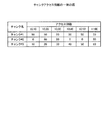
また、配分率管理部102は、ディスク203の種類毎のレスポンスタイムの代表値を予め記憶する。ここで、ディスク203のレスポンスタイムは、ディスク203の種類、I/Oの種類及びI/Oサイズに依存する。このうちI/Oサイズは、高速なレスポンスタイムを求める処理においては、小さなサイズで発行されることが多い。そこで、配分率管理部102は、I/Oサイズが小さい場合の平均的なレスポンスタイムの値を代表値として記憶する。例えば、配分率管理部102は、図6に示すようなレスポンスタイム情報152を記憶している。図6は、レスポンスタイム情報の一例の図である。ここで、図6では、RAIDの種類としてRAID1及び5しか記載していないが、実際には、他のRAIDの種類に対応するレスポンスも配分率管理部102は記憶している。
In addition, the distribution
配分率管理部102は、選択ボリュームのRAID構成の情報をボリュームテーブル142から取得する。次に、配分率管理部102は、選択ボリュームのRAID構成に合わせて、ディスク203の種類毎のReadの場合のレスポンスタイム及びWriteの場合のレスポンスタイムを取得する。
The distribution
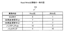
ここで、使用されるI/Oの種類は、業務によってその割合が変わってくる。そこで、配分率管理部102は、業務に応じたRead/Write比の情報を保持しておく。例えば、配分率管理部102は、図7に示すようなRead/Write比情報153を保持している。図7は、Read/Write比情報の一例の図である。
Here, the ratio of the type of I / O used varies depending on the business. Therefore, the distribution
配分率管理部102は、選択ボリュームにデータの読み書きを行う業務の内容をストレージ装置2の処理実行部251から取得する。次に、配分率管理部102は、取得した業務の内容に応じたI/OのRead/Write比をRead/Write比情報153から取得する。そして、次の数式4を用いて選択ボリュームにおけるディスク203の種類毎のレスポンスタイムを求める。
The distribution
次に、配分率管理部102は、アクセス分布関数で使用できる配分率による、ディスク203の種類毎の配分率の組み合わせを生成する。
Next, the distribution
そして、求めたディスク203の種類毎のレスポンスタイムと生成した配分率の組み合わせとを式3に代入し、平均レスポンスタイムを求める。この求めた平均レスポンスタイムが、その配分率の組み合わせで各種類のディスク203を配分した場合の予測レスポンスタイムとなる。
Then, the obtained response time for each type of the
配分率管理部102は、配分率の組み合わせを変更して予測レスポンスタイムの算出を繰り返す。そして、配分率管理部102は、選択ボリュームに設定された目標レスポンスタイムに最も近い値の配分率の組み合わせを特定する。
The distribution
配分率管理部102は、特定した配分率をストレージ装置の性能調整部252へ出力する。
The distribution
設定部101及び配分率管理部102の機能は、例えば、図2のCPU13及びメモリ12で実現される。例えば、HDD14に、設定部101及び配分率管理部102の機能を実現するための各種プログラムが格納される。そして、CPU13は、HDD14から各種プログラムを読み出し、設定部101及び配分率管理部102の機能を実現するプロセスをメモリ12上に展開して実行する。
The functions of the
処理実行部251は、業務用サーバ4で実行されるアプリケーションからのボリューム232に対するデータの読み書きの要求を受ける。そして、処理実行部251は、要求に応じてボリューム232に対してデータの読み書きを行う。また、処理実行部251は、ボリューム232に対するデータの読み書きの要求を発行するアプリケーションの情報を取得し、そのアプリケーションの業務内容を特定する。そして、処理実行部251は、ボリューム232に対するデータの読み書きの要求を発行するアプリケーションの業務内容を配分率管理部102へ通知する。
The
性能調整部252は、ディスク203の種類毎の配分率を配分率管理部102から受信する。そして、性能調整部252は、受信した配分率となるようにボリューム232に、高速ディスク、中速ディスク、低速ディスクの順に割り当てる。そして、性能調整部252は、例えば、アクセス数の高いデータを高速ディスクに格納させ、アクセス数の低いデータを低速ディスクに格納させ、残りのデータを中速ディスクに格納させるなどの処理を行う。
The
処理実行部251及び性能調整部252の機能は、例えば、図2のCPU213及びメモリ214で実現される。例えば、メモリ214に、処理実行部251及び性能調整部252の機能を実現するための各種プログラムが格納される。そして、CPU213は、メモリ214から各種プログラムを読み出し、処理実行部251及び性能調整部252の機能を実現するプロセス生成して実行する。
The functions of the
次に、図8を参照して本実施例に係る運用管理サーバ1によるディスク配分率の調整について説明する。図8は、実施例1に係る運用管理サーバによるディスク配分率の調整処理のフローチャートである。
Next, the adjustment of the disk distribution rate by the
設定部101は、各目標設定ボリュームに対する目標レスポンスタイムの値を操作端末3から受信する(ステップS1)。そして、設定部101は、受信した目標レスポンスタイムを設定テーブル141に登録する。
The
配分率管理部102は、設定テーブル141から目標設定ボリュームを1つ選択する(ステップS2)。
The distribution
次に、配分率管理部102は、選択した目標設定ボリュームに対して実行される業務内容を処理実行部251から取得する(ステップS3)。
Next, the distribution
次に、配分率管理部102は、業務内容に応じたRead/Write比をRead/Write比情報153から取得する。さらに、配分率管理部102は、ディスク203の種類毎のレスポンスタイムをレスポンスタイム情報152から取得する。そして、配分率管理部102は、ディスク203の種類毎に数式4に値を代入し、ディスク203の種類毎のレスポンスタイムを求める(ステップS4)。
Next, the distribution
次に、配分率管理部102は、ディスク203の種類毎の配分率の組み合わせを1つ選択する(ステップS5)。
Next, the distribution
そして、配分率管理部102は、ディスク203の種類毎のレスポンスタイム及び配分率を数式3に代入して配分率に応じた予測レスポンスタイムを算出する(ステップS6)。
Then, the allocation
次に、配分率管理部102は、全ての配分率の組み合わせについて予測レスポンスタイムの算出が完了したか否かを判定する(ステップS7)。予測レスポンスタイムを算出していない配分率の組み合わせが残っている場合(ステップS7:否定)、配分率管理部102は、ステップS5へ戻る。
Next, the distribution
これに対して、全ての配分率の組み合わせに対する予測レスポンスタイムの算出が終了した場合(ステップS7:肯定)、配分率管理部102は、選択した目標設定ボリュームの目標レスポンスタイムに最も予測レスポンスタイムが近い配分率を選択する(ステップS8)。
On the other hand, when the calculation of the predicted response time for all combinations of the distribution ratios is completed (step S7: Yes), the distribution
そして、配分率管理部102は、選択した目標設定ボリュームの配分率として、選択した配分率を性能調整部252へ通知する(ステップS9)。性能調整部252は、配分率管理部102から受信した配分率になるように、各種類のディスク203を目標設定ボリュームに割り当てる。
Then, the distribution
配分率管理部102は、全ての目標設定ボリュームについて配分率の調整を行ったか否かを判定する(ステップS10)。配分率の調整を行っていない目標設定ボリュームが残っている場合(ステップS10:否定)、配分率管理部102は、ステップS2へ戻る。
The distribution
これに対して、全ての目標設定ボリュームについて配分率の調整が完了した場合(ステップS10:肯定)、配分率管理部102は、配分率の調整の処理を終了する。
On the other hand, when the adjustment of the distribution rate is completed for all target setting volumes (step S10: Yes), the distribution
以上に説明したように、本実施例に係るストレージ管理装置は、ボリュームに対する目標レスポンスタイムの入力を受けて、ボリュームの性能が目標値に近づくようにディスク203の種類毎の配分率を調整する。レスポンスタイムは分かり易い目安であり、操作者が容易に設定できるので、本実施例に係るストレージ管理装置は、ストレージ装置の自動階層化における容易な性能調整に寄与することができる。
As described above, the storage management apparatus according to the present embodiment receives the input of the target response time for the volume, and adjusts the distribution rate for each type of the
さらに、本実施例に係るストレージ管理装置は、統計的に取得した固定値をアクセス分布関数及びレスポンスタイムとして使用するので、計算が簡単であり、処理負荷を軽減することができる。 Furthermore, since the storage management apparatus according to the present embodiment uses the statistically acquired fixed values as the access distribution function and the response time, the calculation is simple and the processing load can be reduced.
(変形例)
実施例1では、性能の評価指標として目標レスポンスタイムを用いた。ただし、評価指標は、これに限らず、IOPSやスループットを用いることもできる。そこで、以下に、異なる評価指標を用いた場合について説明する。
(Modification)
In Example 1, the target response time was used as a performance evaluation index. However, the evaluation index is not limited to this, and IOPS and throughput can also be used. Therefore, a case where different evaluation indexes are used will be described below.
まず、IOPSを評価指標として用いる場合について説明する。設定部101は、目標値として最大IOPSの入力を操作端末3から受ける。
First, the case where IOPS is used as an evaluation index will be described. The
配分率管理部102は、ディスク203の種類毎のIOPSの代表値を記憶している。ここで、IOPSは、ディスク203の種類、RAID構成、I/Oの種類、I/Oサイズに依存する。このうちI/Oサイズは、高いIOPSを求める処理の場合、主に小さなサイズで発行されることが多いことから、配分率管理部102は、小さいI/Oサイズでの平均的な値を代表値として記憶する。また、IOPSは、RAID構成の影響を基礎となる構成を基に一次方程式で表すことができる。そして、一次方程式で表した場合、係数はRAID構成に依存する。そこで、配分率管理部102は、RAID構成毎の係数も記憶する。
The distribution
配分率管理部102は、例えば、図9に示すIOPS情報161を記憶している。図9は、IOPS情報の一例の図である。基礎性能ディスク数は、そのRAID構成における最小の構成でのストライプディスクの数であり、1つのデータを書き込む場合にデータを分散させるディスク203の数を表す。
The distribution
配分率管理部102は、選択ボリュームのRAID構成の情報をボリュームテーブル142から取得する。次に、配分率管理部102は、選択ボリュームのRAID構成に合わせて、ディスク203の種類毎の基礎性能ディスク数、基礎性能IOPS及び係数を取得する。そして、配分率管理部102は、取得した基礎性能ディスク数、基礎性能IOPS及び係数を次の数式5に代入して、ディスク203の種類毎の標準最大IOPSを求める。
The distribution
また、IOPSも、Read処理とWrite処理とでは差が発生する。そこで、配分率管理部102は、評価指標がIOPSの場合も、図7のRead/Write比情報153を用いて業務内容によって適切な最大IOPSに補正する。具体的には、次の数式6を用いて最大IOPSを求める。
Also, there is a difference in IOPS between Read processing and Write processing. Therefore, even when the evaluation index is IOPS, the distribution
そして、配分率管理部102は、数式1のレスポンスタイムを最大IOPSに置き換えた次の数式7を用いて、平均IOPSを求め、その値を予測最大IOPSとする。その後、配分率管理部102は、レスポンスタイムの場合と同様に配分率の決定を行う。
Then, the distribution
![]()
![]()
次に、スループットを評価指標として用いる場合について説明する。設定部101は、目標スループットの入力を操作端末3から受ける。
Next, a case where the throughput is used as an evaluation index will be described. The
配分率管理部102は、ディスク203の種類毎のスループットの代表値を記憶している。ここで、スループットは、シーケンシャルI/Oについての指標とすることが好ましい。すなわち、スループットは、I/OサイズやI/Oのブロックサイズにより変化するが、高いスループットを求める処理の場合、I/Oは主に大きなサイズで発行されることが多い。そこで、配分率管理部102は、大きいI/Oサイズでの平均的な値を代表値として記憶する。また、スループットも、RAID構成の影響を基礎となる構成を基に一次方程式で表すことができる。そして、一次方程式で表した場合、係数はRAID構成に依存する。そこで、配分率管理部102は、RAID構成毎の係数も記憶する。
The distribution
配分率管理部102は、例えば、図10に示すスループット情報162を記憶している。図10は、スループット情報の一例の図である。
The distribution
そして、配分率管理部102は、選択ボリュームのRAID構成の情報をボリュームテーブル142から取得する。そして、配分率管理部102は、選択ボリュームのRAID構成に合わせて、ディスク203の種類毎の基礎性能ディスク数、基礎性能スループット及び係数を取得する。そして、配分率管理部102は、取得した基礎性能ディスク数、基礎性能スループット及び係数を次の数式8に代入して、ディスク203の種類毎の標準スループットを求める。
Then, the distribution
また、スループットも、Read処理とWrite処理とでは差が発生する。そこで、配分率管理部102は、評価指標がスループットの場合も、図7のRead/Write比情報153を用いて業務内容によって適切なスループットに補正する。具体的には、次の数式9を用いてスループットを求める。
Also, the throughput differs between the Read process and the Write process. Therefore, even when the evaluation index is throughput, the allocation
そして、配分率管理部102は、数式1のレスポンスタイムをスループットに置き換えた次の数式10を用いて、平均スループットを求め、その値を予測スループットとするその後は、配分率管理部102は、レスポンスタイムの場合と同様に配分率の決定を行う。
Then, the allocation
以上に説明したように、性能の評価指標としてIOPSやスループットを用いた場合にも、本変形例に係る運用管理サーバは、ストレージ装置の自動階層化における容易な性能調整に寄与することができる。このように、評価指標は特定のものに制限されず、ボリュームの性能を評価できる情報であれば特に制限はない。 As described above, even when IOPS or throughput is used as a performance evaluation index, the operation management server according to the present modification can contribute to easy performance adjustment in automatic tiering of storage devices. Thus, the evaluation index is not limited to a specific one, and is not particularly limited as long as it is information that can evaluate the performance of the volume.
図11は、実施例2に係る運用管理サーバ及びストレージ装置のブロック図である。本実施例に係る運用管理サーバ1は、ストレージ装置の性能を計測し、計測結果を用いてアクセス頻度関数及びディスク203の種類毎のレスポンスタイムを求める。そこで、以下では、アクセス頻度関数及びレスポンスタイムの算出について主に説明する。以下の説明では、実施例1と同様の各部の機能については説明を省略する。
FIG. 11 is a block diagram of the operation management server and the storage apparatus according to the second embodiment. The
本実施例に係る運用管理サーバ1は、実施例1の構成に加えて監視部103を有する。また、記憶部104には、ボリューム性能情報ファイル143がさらに格納されている。
The
ボリューム性能情報ファイル143は、各ボリューム232の実測の性能を表す情報が登録されている。本実施例では、ボリューム性能情報ファイル143には、測定を行った性能測定日時と共に、ボリューム識別情報、ボリュームに含まれるチャンクのチャンク識別情報が登録されている。さらに、ボリューム性能情報ファイル143は、チャンク毎に、実測レスポンスタイム、実測スループット及び実測IOPSが対応付けられて登録されている。以下では、チャンク識別情報、並びに、チャンク毎の実測レスポンスタイム、実測スループット及び実測IOPSをまとめて、「チャンクの性能情報」という場合がある。
In the volume
実測レスポンスタイムは、チャンクに対してデータの読み書きを行った際に計測したレスポンスタイムである。実測スループットは、チャンクに対してデータの読み書きを行った際に計測したスループットである。実測IOPSは、チャンクに対してデータの読み書きを行った際に計測したIOPSである。 The measured response time is a response time measured when data is read from or written to the chunk. The actually measured throughput is a throughput measured when reading / writing data from / to a chunk. The measured IOPS is an IOPS measured when data is read from or written to the chunk.
さらに、ボリューム性能情報ファイル143は、ボリューム232に割り当てられている各種類のディスク203のチャンク毎のアクセス数が登録されている。このアクセス数は、前回の配分率の調整から現在までの各チャンクのアクセス数である。以下では、チャンクを4つに分けた場合で説明する。チャンクの分割は同じサイズに分割されるように行われる。
Furthermore, the volume performance information file 143 registers the number of accesses for each chunk of each type of
ただし、各ディスク203にチャンクは大量にあり、チャンクの分割数はこれに限らない。チャンクの分割数は、ディスク203の種類毎の配分率の刻み幅と同じ粒度で設定することが好ましい。例えば、配分率が1%刻みの場合、チャンクを100のグループに分割することが好ましい。
However, each
監視部103は、性能情報取得部253からチャンクの性能情報を定期的に受信する。そして、監視部103は、受信した各ボリューム232に含まれるチャンクの性能情報をボリューム性能情報ファイル143に書き込む。監視部103の機能も、例えば、図2のCPU13及びメモリ12で実現される。例えば、HDD14に、監視部103の機能を実現するための各種プログラムが格納される。そして、CPU13は、HDD14から各種プログラムを読み出し、監視部103の機能を実現するプロセスをメモリ12上に展開して実行する。
The
配分率管理部102は、各チャンクのアクセス数をボリューム性能情報ファイル143から取得する。例えば、配分率管理部102は、取得したアクセス数から図12に示すようなアクセス数集計表171を作成する。ここで、アクセス数集計表171における、チャンク#1〜#4は、4分割されたチャンクを表している。図12は、アクセス数集計表の一例の図である。
The distribution
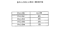
分割されたチャンクのサイズは一定であるので、チャンク#1〜#4におけるアクセス数の割合が、チャンク#1〜#4に対するヒット率となる。すなわち、配分率管理部102は、アクセス数集計表171から図13で表されるチャンク#1〜#4に対するヒット率を求める。図13は、各チャンクのヒット率の一例を表す図である。
Since the size of the divided chunks is constant, the ratio of the number of accesses in the
また、各チャンクのサイズの割合がアクセス頻度の割合に対応する。そこで、配分率管理部102は、図14のように、アクセス頻度の割合とヒット率との対応を表す関数を生成することで、アクセス分布関数172を生成することができる。図14は、配分率管理部が生成したアクセス分布関数の一例を表す図である。
Further, the ratio of the size of each chunk corresponds to the ratio of access frequency. Therefore, the distribution
また、配分率管理部102は、各チャンクが属するディスク203の種類及び各チャンクのレスポンスタイムをボリューム性能情報ファイル143からから取得する。そして、配分率管理部102は、各チャンクに対する平均レスポンスタイムを算出する。さらに、配分率管理部102は、各チャンクに使用されているディスク種別を基に、各チャンクに対する平均レスポンスタイムからディスク203の種類毎の平均レスポンスタイムを、ディスク203の種類毎のレスポンスタイムとして算出する。
Further, the distribution
そして、配分率管理部102は、配分率の組み合わせを選択し、生成したアクセス分布関数172及び算出したディスク203の種類毎のレスポンスタイムを数式3に用いて予想レスポンスタイムを算出する。その後、配分率管理部102は、実施例1と同様の処理により配分率の決定を行う。
Then, the distribution
性能情報取得部253は、性能収集開始の指示を監視部103から受ける。そして、性能情報取得部253は、各ボリューム232の性能情報を定期的に取得し、監視部103へ送信する。また、性能情報取得部253は、各リソースの性能情報を定期的に取得し、監視部103へ送信する。
The performance
性能情報取得部253の機能も、例えば、図2のCPU213及びメモリ214で実現される。例えば、メモリ214に、性能情報取得部253の機能を実現するための各種プログラムが格納される。そして、CPU213は、メモリ214から各種プログラムを読み出し、性能情報取得部253の機能を実現するプロセス生成して実行する。
The function of the performance
以上に説明したように、本実施理に係るストレージ管理装置は、測定したアクセス数及びレスポンスタイムを用いて、アクセス分布関数及びレスポンスタイムを求め、配分率を決定する。このように、本実施例に係るストレージ管理装置は、実測値を基に配分率を決定するため、より正確に目標レスポンスタイムに近づけるように配分率の調整を行うことができる。 As described above, the storage management device according to the present embodiment obtains an access distribution function and response time using the measured number of accesses and response time, and determines an allocation rate. As described above, the storage management apparatus according to the present embodiment determines the distribution rate based on the actual measurement value, and thus can adjust the distribution rate so as to approach the target response time more accurately.
(変形例)
実施例2では、性能の評価指標として目標レスポンスタイムを用いた。ただし、実施例2の機能を有するストレージ管理装置においても評価指標として、IOPSやスループットを用いることもできる。そこで、以下に、異なる評価指標を用いた場合について説明する。
(Modification)
In Example 2, the target response time was used as a performance evaluation index. However, IOPS and throughput can also be used as an evaluation index in the storage management apparatus having the function of the second embodiment. Therefore, a case where different evaluation indexes are used will be described below.
まず、IOPSを評価指標として用いる場合について説明する。配分率管理部102は、アクセス分布関数については、実施例2と同様に生成する。
First, the case where IOPS is used as an evaluation index will be described. The distribution
次に、配分率管理部102は、各チャンクが属するディスク203の種類及び各チャンクのIOPSをボリューム性能情報ファイル143からから取得する。ここで、IOPSは、1秒当たりのI/O数を示す指標である。そのため、IOPSは、所定期間監視した値から算出される。ただし、監視時間が長い場合、I/O負荷の変動からディスク性能が100%とならなくなるおそれがあり、配分率管理部102は、頻繁に補正を行うために負荷が高くなってしまう。そこで、IOPSの監視時間は短い時間で設定されることが好ましい。
Next, the distribution
そして、配分率管理部102は、各チャンクに対する平均IOPSを算出する。具体的には、配分率管理部102は、監視時間におけるI/O回数を監視時間で除算することで平均IOPSを求める。さらに、配分率管理部102は、各チャンクに使用されているディスク種別を基に、各チャンクに対する平均IOPSからディスク203の種類毎の平均IOPSを算出する。
Then, the distribution
ここで、配分率管理部102が算出した平均IOPSは、チャンクが含まれるディスク203に対するホストからのI/O負荷率が低い場合、そのチャンクで処理できる最大IOPSより低い値が算出される。そこで、配分率管理部102は、各ディスク203のビジー率をボリューム性能情報ファイル143から取得する。そして、配分率管理部102は、レスポンスタイムを求めるチャンクを含むディスク203のビジー率が100%の場合には、算出した平均IOPSをそのチャンクのIOPSとして用いる。また、レスポンスタイムを求めるチャンクを含むディスク203のビジー率が100%より低い場合には、配分率管理部203は、最大性能下でのIOPSとなるように補正した値をチャンクのIOPSとして用いる。
Here, when the I / O load rate from the host with respect to the
具体的には、配分率管理部102は、次の数式11を用いてIOPSを算出する。
Specifically, the distribution
![]()
![]()
ここで、係数とは、ディスク203の種類に応じて事前にビジー率とIOPSとの関係を測定した結果から得られる値である。ただし、ビジー率とIOPSとは単純に比例するとは限らないので、各ビジー率に応じた代表的な値を係数として用いる。例えば、係数は次の数式12により求められる。
Here, the coefficient is a value obtained from the result of measuring the relationship between the busy rate and IOPS in advance according to the type of the
![]()
![]()
配分率管理部102は、算出したチャンク毎のIOPSにおいて、同じ種類のディスク203に含まれるチャンクが存在する場合、補正なしで最も性能が良い値をその種類のディスク203のIOPSとする。そして、配分率管理部102は、算出したディスク203の種類毎のIOPSを登録する。例えば、配分率管理部102は、図15に示すようなIOPS情報テーブル173に算出したディスク203の種類毎のIOPSを登録して、情報を保持する。図15は、IOPS情報テーブルの一例の図である。
When there is a chunk included in the same type of
そして、配分率管理部102は、以上に説明したディスク203の種類毎のIOPSの算出を配分率の調整のタイミングまで繰り返し実行する。そして、次の3つの条件のいずれかに当てはまる場合、配分率管理部102は、登録しているIOPSの値を新しく算出したIOPSに更新する。
Then, the distribution
第1の条件は、登録されている値に補正が行われており、新しく求めた値には補正が行われていない場合である。第2の条件は、登録されている値及び新しく求めた値のいずれも、補正が行われておらず、新しく求めた値が登録されている値よりも大きい場合である。第3の条件は、登録されている値及び新しく求めた値のいずれも、補正が行われており、新しく求めた値が登録されている値よりも大きい場合である。 The first condition is when the registered value is corrected and the newly obtained value is not corrected. The second condition is a case where neither the registered value nor the newly obtained value is corrected, and the newly obtained value is greater than the registered value. The third condition is a case where both the registered value and the newly obtained value are corrected, and the newly obtained value is greater than the registered value.
そして、配分率管理部102は、配分率の調整の実施タイミングになった時に、その時点でIOPS情報テーブル173に登録されているIOPSをディスク203の種類毎のIOPSとして取得する。
The distribution
また、スループットを評価指標とする場合、配分率管理部102は、評価指標をIOPSと同様の方法でのディスク203の種類毎のスループットを算出することができる。詳細には、スループットは、業務サーバ4からストレージ装置2への単位時間あたりの転送ブロック数である。そこで、スループットを評価指標とする場合、配分率管理部102は、I/O回数に変えて転送ブロック数を取得する。それ以外の処理については評価指標をIOPSとした場合と同様である。
Further, when the throughput is used as an evaluation index, the allocation
以上に説明したように、性能の評価指標としてIOPSやスループットを用いた場合にも、本変形例に係る運用管理サーバは、実施例2と同様の効果を得ることができる。このように、評価指標は特定のものに制限されず、ボリュームの性能を評価できる情報であれば特に制限はない。 As described above, even when IOPS or throughput is used as the performance evaluation index, the operation management server according to the present modification can obtain the same effects as those of the second embodiment. Thus, the evaluation index is not limited to a specific one, and is not particularly limited as long as it is information that can evaluate the performance of the volume.
次に、実施例3について説明する。本実施例に係る運用管理サーバ1は、ボリューム232のレスポンスタイムを計測し、目標レスポンスタイムと実測レスポンスタイムとの比較を基に配分率を調整していく。そこで、以下では、目標レスポンスタイムと実測レスポンスタイムとを用いた配分率の調整について主に説明する。本実施例に係る運用管理サーバ1及びストレージ装置2も図11で表される。以下の説明では、実施例1と同様の各部の機能については説明を省略する。
Next, Example 3 will be described. The
本実施例に係るボリューム性能情報ファイル143は、測定を行った性能測定日時と共に、ボリューム識別情報、ボリューム毎の、実測レスポンスタイム、実測スループット及び実測IOPSが対応付けられて登録されている。以下では、ボリューム識別情報、チャンク識別情報、実測レスポンスタイム、実測スループット及び実測IOPSをまとめて、「ボリュームの性能情報」という場合がある。 In the volume performance information file 143 according to the present embodiment, the volume identification information, the measured response time for each volume, the measured throughput, and the measured IOPS are registered in association with the performance measurement date and time when the measurement was performed. Hereinafter, the volume identification information, chunk identification information, measured response time, measured throughput, and measured IOPS may be collectively referred to as “volume performance information”.
ボリューム毎の実測レスポンスタイムは、ボリューム232に対してデータの読み書きを行った際に計測したレスポンスタイムである。実測スループットは、ボリューム232に対してデータの読み書きを行った際に計測したスループットである。実測IOPSは、ボリューム232に対してデータの読み書きを行った際に計測したIOPSである。
The actual response time for each volume is a response time measured when data is read from or written to the
監視部103は、性能情報取得部253からボリューム性能情報を定期的に受信する。そして、監視部103は、受信した各ボリューム性能情報をボリューム性能情報ファイル143に書き込む。
The
配分率管理部102は、配分率の調整後に、調整に用いたディスク203の種類毎の配分率を記憶部104に記憶させる。例えば、配分率管理部102は、記憶部104の設定テーブル141に配分率の欄を設けて登録してもよい。ここでは、記憶部104が記憶している配分率をそれぞれ、「高速ディスク配分率」、「中速ディスク配分率」及び「低速ディスク配分率」とする。
After the distribution rate is adjusted, the distribution
また、配分率管理部102は、配分率の調整幅として「増減量」を予め記憶している。増減量は、配分率を変化させる上限値であり、0〜100%に含まれる値である。本実施例では、配分率管理部102は、増減量として0〜100%に含まれる固定値を記憶している。
In addition, the distribution
また、配分率管理部102は、異なる種類のディスク203の配分率を同時に増加又は減少させる場合のディスク203の種類毎の配分率をどれだけ移動するかの値である「ディスクへの移動率」を予め記憶している。本実施例では、配分率管理部102は、高速ディスクと中速ディスクとを同時に増加させる場合のそれぞれのディスクへの移動率を0〜100%に含まれる固定値として記憶している。また、配分率管理部102は、中速ディスクと低速ディスクとを同時に減少させる場合のそれぞれのディスクへの移動率を0〜100%に含まれる固定値として記憶している。このディスクへの移動率は、運用管理サーバ1を用いて配分率の調整を行う際に操作者が指定してもよいし、システムの管理者が予め指定しておいてもよい。
Further, the distribution
配分率管理部102は、目標設定ボリュームを選択する。そして、配分率管理部102は、選択した目標設定ボリュームの実測レスポンスタイムをボリューム性能情報ファイル143から取得する。また、配分率管理部102は、選択した目標設定ボリュームの目標レスポンスタイムを設定テーブル141から取得する。
The distribution
さらに、配分率管理部102は、高速ディスク配分率、中速ディスク配分率及び低速ディスク配分率を記憶部104から取得する。
Further, the distribution
そして、配分率管理部102は、目標レスポンスタイムと実測レスポンスタイムとを比較する。
Then, the distribution
実測レスポンスタイムと目標レスポンスタイムとが等しい場合、配分率管理部102は、配分率の調整を行わず処理を終了する。
If the measured response time is equal to the target response time, the distribution
これに対して、実測レスポンスタイムが目標レスポンスタイムより大きい場合、すなわち、実際の性能が目標値まで達していない場合は、配分率管理部102は、以下の処理を行う。
On the other hand, when the measured response time is larger than the target response time, that is, when the actual performance has not reached the target value, the allocation
高速ディスク配分率が100%であれば、配分率の調整が不可能なので、配分率管理部102は、配分率の調整の処理を終了する。
If the high-speed disk allocation rate is 100%, it is impossible to adjust the allocation rate, and the allocation
また、高速ディスク配分率に増減量を加算した値が100%以上であれば、配分率管理部102は、高速ディスク配分率を100%に変更し、中速ディスク配分率及び低速ディスク配分率を0%に変更する。
If the value obtained by adding the increase / decrease amount to the high-speed disk distribution rate is 100% or more, the distribution
また、低速ディスク配分率が0%であり、且つ、中速ディスク配分率から増減量を減算した値が0%以上の場合、配分率管理部102は、高速ディスク配分率に増減量を加算した値を高速ディスク配分率とする。また、配分率管理部102は、中速ディスク配分率から増減量を減算した値を中速ディスク配分率とする。
Further, when the low-speed disk allocation rate is 0% and the value obtained by subtracting the increase / decrease amount from the medium-speed disk allocation rate is 0% or more, the allocation
また、低速ディスク配分率が0%であり、且つ、中速ディスク配分率から増減量を減算した値が0%未満の場合、配分率管理部102は、高速ディスク配分率に中速ディスク配分率を加算した値を高速ディスク配分率とする。そして、配分率管理部102は、中速ディスク配分率を0%とする。
When the low-speed disk distribution rate is 0% and the value obtained by subtracting the increase / decrease amount from the medium-speed disk distribution rate is less than 0%, the distribution
また、低速ディスク配分率から増減量を減算した値が0%以上の場合、配分率管理部102は、増減量に高速ディスクへの移動率を乗算した値を高速ディスク配分率に加算した結果を高速ディスク配分率とする。また、配分率管理部102は、増減量に中速ディスクの移動率を乗算した値に中速ディスク配分率を加算した結果を中速ディスク配分率とする。さらに、配分率管理部102は、低速ディスク配分率から増減量を減算した値を低速ディスク配分率とする。
When the value obtained by subtracting the increase / decrease amount from the low-speed disk distribution rate is 0% or more, the distribution
また、低速ディスク配分率から増減量を減算した値が0%未満の場合、配分率管理部102は、高速ディスク配分率に低速ディスク配分率を加算した値を高速ディスク配分率とする。そして、配分率管理部102は、低速ディスク配分率を0%とする。
When the value obtained by subtracting the increase / decrease amount from the low-speed disk distribution rate is less than 0%, the distribution
これに対して、実測レスポンスタイムが目標レスポンスタイムより小さい場合、すなわち、実際の性能が目標値を超えている場合は、配分率管理部102は、以下の処理を行う。
On the other hand, when the measured response time is smaller than the target response time, that is, when the actual performance exceeds the target value, the distribution
低速ディスク配分率が100%であれば、配分率の調整が不可能なので、配分率管理部102は、配分率の調整の処理を終了する。
If the low-speed disk allocation rate is 100%, the allocation rate cannot be adjusted, and the allocation
また、低速ディスク配分率に増減量を加算した値が100%以上であれば、配分率管理部102は、低速ディスク配分率を100%に変更し、高速ディスク配分率及び中速ディスク配分率を0%に変更する。
If the value obtained by adding the increase / decrease amount to the low-speed disk distribution rate is 100% or more, the distribution
また、高速ディスク配分率が0%であり、且つ、中速ディスク配分率から増減量を減算した値が0%以上の場合、配分率管理部102は、低速ディスク配分率に増減量を加算した値を低速ディスク配分率とする。また、配分率管理部102は、中速ディスク配分率から増減量を減算した値を中速ディスク配分率とする。
Further, when the high-speed disk allocation rate is 0% and the value obtained by subtracting the increase / decrease amount from the medium-speed disk allocation rate is 0% or more, the allocation
また、高速ディスク配分率が0%であり、且つ、中速ディスク配分率から増減量を減算した値が0%未満の場合、配分率管理部102は、低速ディスク配分率に中速ディスク配分率を加算した値を低速ディスク配分率とする。そして、配分率管理部102は、中速ディスク配分率を0%とする。
When the high-speed disk distribution rate is 0% and the value obtained by subtracting the increase / decrease amount from the medium-speed disk distribution rate is less than 0%, the distribution
また、高速ディスク配分率から増減量を減算した値が0%以上の場合、配分率管理部102は、増減量に低速ディスクへの移動率を乗算した値を低速ディスク配分率に加算した結果を低速ディスク配分率とする。また、配分率管理部102は、増減量に中速ディスクの移動率を乗算した値に中速ディスク配分率を加算した結果を中速ディスク配分率とする。さらに、配分率管理部102は、高速ディスク配分率から増減量を減算した値を高速ディスク配分率とする。
When the value obtained by subtracting the increase / decrease amount from the high-speed disk distribution rate is 0% or more, the distribution
また、高速ディスク配分率から増減量を減算した値が0%未満の場合、配分率管理部102は、低速ディスク配分率に高速ディスク配分率を加算した値を低速ディスク配分率とする。そして、配分率管理部102は、高速ディスク配分率を0%とする。
If the value obtained by subtracting the increase / decrease amount from the high-speed disk distribution rate is less than 0%, the distribution
配分率管理部102は、変更後の高速ディスク配分率、中速ディスク配分率及び低速ディスク配分率を記憶部104に記憶させる。
The distribution
次に、図16を参照して、本実施例に係る運用管理サーバ1による配分率の調整処理の全体的な流れを説明する。図16は、実施例3に係る運用管理サーバによる配分率の調整処理のフローチャートである。図16は、1つの目標設定ボリュームに対する配分率の調整処理を表している。実際には、運用管理サーバ1は、全ての目標設定ボリュームに対して図16の処理を行う。
Next, with reference to FIG. 16, the overall flow of the distribution rate adjustment processing by the
配分率管理部102は、目標レスポンスタイムを設定テーブル141から取得する(ステップS101)。
The distribution
次に、配分率管理部102は、実測レスポンスタイムをボリューム性能情報ファイル143から取得する(ステップS102)。
Next, the distribution
次に、配分率管理部102は、記憶部104に記憶されている高速ディスク配分率、中速ディスク配分率及び低速ディスク配分率を取得する(ステップS103)。
Next, the distribution
次に、配分率管理部102は、実測レスポンスタイムが目標レスポンスタイムより大きいか否かを判定する(ステップS104)。実測レスポンスタイムが目標レスポンスタイムより大きい場合(ステップS104:肯定)、配分率管理部102は、レスポンスタイムが向上するように配分率を変更する(ステップS105)。
Next, the distribution
これに対して、実測レスポンスタイムが目標レスポンスタイム以下の場合(ステップS104:否定)、配分率管理部102は、実測レスポンスタイムが目標レスポンスタイムより小さいか否かを判定する(ステップS106)。
On the other hand, when the actual response time is equal to or shorter than the target response time (No at Step S104), the allocation
実測レスポンスタイムが目標レスポンスタイムより小さい場合(ステップS106:肯定)、配分率管理部102は、レスポンスタイムを抑制するように配分率を変更する(ステップS107)。
When the measured response time is smaller than the target response time (step S106: affirmative), the distribution
これに対して、実測レスポンスタイムと目標レスポンスタイムが等しい場合(ステップS106:否定)、配分率管理部102は、ステップS108へ進む。
On the other hand, when the measured response time is equal to the target response time (No at Step S106), the distribution
そして、配分率管理部102は、調整後の高速ディスク配分率、中速ディスク配分率、低速ディスク配分率を記憶部104に格納する(ステップS108)。
Then, the distribution
次に、図17を参照して、レスポンスタイムを向上させる場合の配分率変更処理について説明する。図17は、レスポンスタイムを向上させる場合の配分率変更処理のフローチャートである。図17の処理は、図16のステップS105の処理の一例にあたる。 Next, with reference to FIG. 17, the distribution rate changing process for improving the response time will be described. FIG. 17 is a flowchart of the distribution rate changing process for improving the response time. The process in FIG. 17 corresponds to an example of the process in step S105 in FIG.
配分率管理部102は、高速ディスク配分率が100%か否か判定する(ステップS201)。高速ディスク配分率が100%の場合(ステップS201:肯定)、配分率管理部102は、処理を終了する。
The distribution
これに対して、高速ディスク配分率が100%でない場合(ステップS201:否定)、配分率管理部102は、高速ディスク配分率に増減量を加算した値が100%以上か否かを判定する(ステップS202)。
On the other hand, when the high-speed disk distribution rate is not 100% (No at Step S201), the distribution
高速ディスク配分率に増減量を加算した値が100%以上の場合(ステップS202:肯定)、配分率管理部102は、高速ディスク配分率を100%とし、中速及び低速ディスク配分率を0%とする(ステップS203)。
When the value obtained by adding the increase / decrease amount to the high-speed disk distribution rate is 100% or more (step S202: Yes), the distribution
これに対して、高速ディスク配分率に増減量を加算した値が100%より小さい場合(ステップS202:否定)、配分率管理部102は、低速ディスク配分率が0%か否かを判定する(ステップS204)。
On the other hand, when the value obtained by adding the increase / decrease amount to the high-speed disk distribution rate is smaller than 100% (No at Step S202), the distribution
低速ディスク配分率が0%の場合(ステップS204:肯定)、配分率管理部102は、中速ディスク配分率から増減量を減算した値が0%以上か否かを判定する(ステップS205)。
When the low-speed disk distribution rate is 0% (step S204: Yes), the distribution
中速ディスク配分率から増減量を減算した値が0%以上の場合(ステップS205:肯定)、配分率管理部102は、高速ディスク配分率に増減量を加算した値を高速ディスク配分率とする。さらに、配分率管理部102は、中速ディスク配分率から増減量を減算した値を中速ディスク配分率とする(ステップS206)。
When the value obtained by subtracting the increase / decrease amount from the medium speed disk distribution rate is 0% or more (step S205: Yes), the distribution
これに対して、中速ディスク配分率から増減量を減算した値が0%未満の場合(ステップS205:否定)、配分率管理部102は、高速ディスク配分率に中速ディスク配分率を加算した値を高速ディスク配分率とする。さらに、配分率管理部102は、中速ディスク配分率を0%とする(ステップS207)。
On the other hand, when the value obtained by subtracting the increase / decrease amount from the medium speed disk distribution ratio is less than 0% (No at Step S205), the distribution
一方、低速ディスク配分率が0%でない場合(ステップS204:否定)、配分率管理部102は、低速ディスク配分率から増減量を減算した値が0%以上か否かを判定する(ステップS208)。
On the other hand, when the low-speed disk distribution rate is not 0% (No at Step S204), the distribution
低速ディスク配分率から増減量を減算した値が0%以上の場合(ステップS208:肯定)、配分率管理部102は、増減量に高速ディスクへの移動率を乗算した結果に高速ディスク配分率を加算した値を高速ディスク配分率とする。また、配分率管理部102は、増減量に中速ディスクへの移動率を乗算した結果に中速ディスク配分率を加算した値を中速ディスク配分率とする。さらに、配分率管理部102は、低速ディスク配分率から増減量を減算した値を低速ディスク配分率とする(ステップS209)。
When the value obtained by subtracting the increase / decrease amount from the low-speed disk allocation rate is 0% or more (step S208: Yes), the allocation
これに対して、低速ディスク配分率から増減量を減算した値が0%未満の場合(ステップS208:否定)、配分率管理部102は、高速ディスク配分率に低速ディスク配分率を加算した値を高速ディスク配分率とする。さらに、配分率管理部102は、低速ディスク配分率を0%とする(ステップS210)。
On the other hand, when the value obtained by subtracting the increase / decrease amount from the low-speed disk distribution rate is less than 0% (No at Step S208), the distribution
次に、図18を参照して、レスポンスタイムを抑制する場合の配分率変更処理について説明する。図18は、レスポンスタイムを抑制する場合の配分率変更処理のフローチャートである。図18の処理は、図16のステップS107の処理の一例にあたる。 Next, with reference to FIG. 18, the distribution rate changing process in the case of suppressing the response time will be described. FIG. 18 is a flowchart of the distribution rate changing process when the response time is suppressed. The process in FIG. 18 corresponds to an example of the process in step S107 in FIG.
配分率管理部102は、低速ディスク配分率が100%か否か判定する(ステップS301)。低速ディスク配分率が100%の場合(ステップS301:肯定)、配分率管理部102は、処理を終了する。
The distribution
これに対して、低速ディスク配分率が100%でない場合(ステップS301:否定)、配分率管理部102は、低速ディスク配分率に増減量を加算した値が100%以上か否かを判定する(ステップS302)。
On the other hand, if the low-speed disk distribution rate is not 100% (No at Step S301), the distribution
低速ディスク配分率に増減量を加算した値が100%以上の場合(ステップS302:肯定)、配分率管理部102は、低速ディスク配分率を100%とし、高速及び中速ディスク配分率を0%とする(ステップS303)。
When the value obtained by adding the increase / decrease amount to the low-speed disk distribution rate is 100% or more (step S302: Yes), the distribution
これに対して、低速ディスク配分率に増減量を加算した値が100%より小さい場合(ステップS302:否定)、配分率管理部102は、高速ディスク配分率が0%か否かを判定する(ステップS304)。
On the other hand, when the value obtained by adding the increase / decrease amount to the low-speed disk distribution rate is smaller than 100% (No at Step S302), the distribution
高速ディスク配分率が0%の場合(ステップS304:肯定)、配分率管理部102は、中速ディスク配分率から増減量を減算した値が0%以上か否かを判定する(ステップS305)。
When the high-speed disk distribution rate is 0% (step S304: Yes), the distribution
中速ディスク配分率から増減量を減算した値が0%以上の場合(ステップS305:肯定)、配分率管理部102は、低速ディスク配分率に増減量を加算した値を低速ディスク配分率とする。さらに、配分率管理部102は、中速ディスク配分率から増減量を減算した値を中速ディスク配分率とする(ステップS306)。
When the value obtained by subtracting the increase / decrease amount from the medium speed disk distribution rate is 0% or more (step S305: Yes), the distribution
これに対して、中速ディスク配分率から増減量を減算した値が0%未満の場合(ステップS305:否定)、配分率管理部102は、低速ディスク配分率に中速ディスク配分率を加算した値を低速ディスク配分率とする。さらに、配分率管理部102は、中速ディスク配分率を0%とする(ステップS307)。
On the other hand, when the value obtained by subtracting the increase / decrease amount from the medium speed disk distribution ratio is less than 0% (No at Step S305), the distribution
一方、高速ディスク配分率が0%でない場合(ステップS304:否定)、配分率管理部102は、高速ディスク配分率から増減量を減算した値が0%以上か否かを判定する(ステップS308)。
On the other hand, when the high-speed disk distribution rate is not 0% (No at Step S304), the distribution
高速ディスク配分率から増減量を減算した値が0%以上の場合(ステップS308:肯定)、配分率管理部102は、増減量に低速ディスクへの移動率を乗算した結果に低速ディスク配分率を加算した値を低速ディスク配分率とする。また、配分率管理部102は、増減量に中速ディスクへの移動率を乗算した結果に中速ディスク配分率を加算した値を中速ディスク配分率とする。さらに、配分率管理部102は、高速ディスク配分率から増減量を減算した値を高速ディスク配分率とする(ステップS309)。
When the value obtained by subtracting the increase / decrease amount from the high-speed disk allocation rate is 0% or more (step S308: Yes), the allocation
これに対して、高速ディスク配分率から増減量を減算した値が0%未満の場合(ステップS308:否定)、配分率管理部102は、低速ディスク配分率に高速ディスク配分率を加算した値を低速ディスク配分率とする。さらに、配分率管理部102は、高速ディスク配分率を0%とする(ステップS310)。
On the other hand, when the value obtained by subtracting the increase / decrease amount from the high-speed disk distribution rate is less than 0% (No at Step S308), the distribution
以上に説明したように本実施例に係るストレージ管理装置は、実測レスポンスタイムと目標レスポンスタイムとを比較し、その差を基にディスクの配分率を変えていく。この場合、配分率の計算が容易であり、ストレージ管理装置の計算能力が低くても処理を行うことができる。 As described above, the storage management apparatus according to the present embodiment compares the actual response time with the target response time, and changes the disk allocation rate based on the difference. In this case, it is easy to calculate the distribution rate, and processing can be performed even if the storage management device has a low calculation capability.
(変形例1)
次に、実施例3に係る運用管理サーバの変形例1について説明する。実施例3では、ディスクの移動率を固定値として用いていた。しかし、ディスクの移動率は変化させてもよい。以下に、ディスクの移動率を変化させる場合の一例について説明する。
(Modification 1)
Next, a first modification of the operation management server according to the third embodiment will be described. In the third embodiment, the disk movement rate is used as a fixed value. However, the movement rate of the disk may be changed. Hereinafter, an example of changing the disk movement rate will be described.
配分率管理部102は、ディスク203の種類毎の空き容量に比例させて、各種類のディスク203への移動率を算出する。以下に、その算出方法を説明する。
The distribution
実測値レスポンスタイムが目標レスポンスタイムより大きく、低速ディスクから容量を減らす場合、配分率管理部102は、以下の処理を行う。
When the actually measured value response time is larger than the target response time and the capacity is reduced from the low-speed disk, the distribution
配分率管理部102は、高速ディスクの空き容量を高速ディスクの空き容量と中速ディスクの空き容量とを加算した値で除算した結果を高速ディスクへの移動率とする。また、配分率管理部102は、中速ディスクの空き容量を高速ディスクの空き容量と中速ディスクの空き容量とを加算した値で除算した結果を中速ディスクへの移動率とする。
The distribution
実測値レスポンスタイムが目標レスポンスタイムより小さく、高速ディスクから容量を減らす場合、配分率管理部102は、以下の処理を行う。
When the actually measured value response time is smaller than the target response time and the capacity is reduced from the high-speed disk, the distribution
配分率管理部102は、中速ディスクの空き容量を中速ディスクの空き容量と低速ディスクの空き容量とを加算した値で除算した結果を中速ディスクへの移動率とする。また、配分率管理部102は、低速ディスクの空き容量を中速ディスクの空き容量と低速ディスクの空き容量とを加算した値で除算した結果を低速ディスクへの移動率とする。
The distribution
配分率管理部102は、算出した各種類のディスクへの移動率を用いて実施例3で説明した方法でディスクの種類毎の配分率を決定する。
The distribution
以上に説明したように、本変形例に係るストレージ管理装置は、各ディスクの空き容量に応じて各種類のディスクへの移動率を変化させる。これにより、配分率の調整後のディスクの種類毎の空き容量の偏りを軽減することができる。 As described above, the storage management apparatus according to this modification changes the migration rate to each type of disk according to the free capacity of each disk. Thereby, it is possible to reduce the deviation of the free capacity for each type of disk after the distribution rate is adjusted.
また、ストレージ管理装置は、ディスクへの移動率を変化させる方法とディスクへの移動率に固定値を使う方法とを併用することもできる。 In addition, the storage management device can use both a method of changing the migration rate to the disk and a method of using a fixed value for the migration rate to the disk.
(変形例2)
次に、実施例3に係る運用管理サーバの変形例2について説明する。実施例3では、増減量を固定値として用いていた。しかし、増減量は変化させてもよい。例えば、目標レスポンスタイムと実測レスポンスタイムとの乖離度合によって増減量を変動させることもできる。以下に、ディスクの移動率を変化させる場合の一例について説明する。
(Modification 2)
Next, a second modification of the operation management server according to the third embodiment will be described. In Example 3, the amount of increase / decrease was used as a fixed value. However, the increase / decrease amount may be changed. For example, the amount of increase / decrease can be varied depending on the degree of deviation between the target response time and the measured response time. Hereinafter, an example of changing the disk movement rate will be described.
配分率管理部102は、目標レスポンスタイムと実測レスポンスタイムとの乖離度合によって増減量を算出する。以下に、その算出方法を説明する。
The distribution
一つの方法として、例えば、配分率管理部102は、図19の増減量情報174を記憶しておく。図19は、増減量情報の一例の図である。
As one method, for example, the distribution
配分率管理部102は、実測レスポンスタイムを目標レスポンスタイムで除算し、その除算結果に対応する増減量を増減量情報174から取得する。そして、配分率管理部102は、取得した増減量を用いて実施例3で説明した方法でディスク203の種類毎の配分率を決定する。
The distribution
また、以上に説明した実施例3、変形例1及び変形例2では、性能の評価指標として目標レスポンスタイムを用いた。しかし、評価指標は、これに限らず、IOPSやスループットを用いてもよい。ただし、レスポンスタイムは数値が大きいほど性能が低いが、最大IOPS及びスループットは数値が大きいほど性能が高い。そこで、最大IOPSやスループットを評価指標として用いる場合、目標値が実測値よりも大きい場合、高速ディスクの配分率を上昇させ、目標値が実測値よりも小さい場合、低速ディスクの配分率を上昇させる。すなわち、最大IOPS又はスループットを性能指標とした場合、目標値と実測値との大小の判定後の処理が、レスポンスタイムを性能指標とした場合の処理と逆になる。 In the third embodiment, the first modification, and the second modification described above, the target response time is used as a performance evaluation index. However, the evaluation index is not limited to this, and IOPS or throughput may be used. However, the larger the response time, the lower the performance, but the higher the maximum IOPS and throughput, the higher the performance. Therefore, when the maximum IOPS or throughput is used as an evaluation index, when the target value is larger than the actual measurement value, the high-speed disk allocation rate is increased, and when the target value is smaller than the actual measurement value, the low-speed disk allocation rate is increased. . That is, when the maximum IOPS or throughput is used as a performance index, the process after the determination of the target value and the actual measurement value is reversed from the process when the response time is used as the performance index.
次に、実施例4について説明する。本実施例に係る運用管理サーバは、短い時間で1回の自動階層化機能による性能調整を完了させる。図20は、実施例4に係る運用管理サーバ及びストレージ装置のブロック図である。ここで、本実施例では、性能目標としてレスポンスタイムを用い、ディスク203の種類毎のレスポンスタイムとアクセス分布関数が予め決定されており近似式を用いて性能調整を行う実施例1の場合で説明する。
Next, Example 4 will be described. The operation management server according to the present embodiment completes the performance adjustment by the automatic tiering function once in a short time. FIG. 20 is a block diagram of the operation management server and the storage apparatus according to the fourth embodiment. Here, in this embodiment, the response time is used as a performance target, the response time and the access distribution function for each type of the
記憶部104は、設定テーブル141、ボリュームテーブル142及びボリューム性能情報ファイル143の他に、チャンク構成情報145の各情報を所定の情報記憶領域に記憶している。記憶部104の管理情報記憶領域は、各テーブルをテーブル化するための情報を記憶しておき、制御時にテーブル化して使用するようにしてもよい。
In addition to the setting table 141, the volume table 142, and the volume
チャンク構成情報145は、図21Aに示すチャンクマッピング情報181、図21Bに示すRAIDグループ対応情報182及び図21Cに示すプール情報183を含んでいる。図21Aは、チャンクマッピング情報の一例の図である。図21Bは、RAIDグループ対応情報の一例の図である。図21Cは、プール情報の一例の図である。
The
チャンクマッピング情報181は、ボリューム232及びRAIDグループ231におけるチャンクのアドレスを示す情報である。RAIDグループ対応情報182は、RAIDグループとその零度グループが含まれるプールとの対応を表す情報である。ここで、プールとは、同じ種類のディスク203で構成された複数のRAIDグループをまとめて一つのグループとした単位である。さらに、プール情報183は、プールの識別情報とそのプールに含まれるディスク203の種類が登録されている。
The
配分率管理部102は、一定周期で性能調整を実行するために動作間隔を記憶している。そして、配分率管理部102は、動作間隔に達すると性能調整の処理を開始する。ここで、動作間隔が短いと、運用管理サーバ1の負荷が高くなる。また、動作間隔が長いと、性能調整の収束速度が遅くなる。そこで、動作間隔は、運用管理サーバ1の負荷と性能調整の収束速度とのバランスを考慮して決定されることが好ましい。例えば、システム管理者は、システム構築時にシステムの管理者が平均的な性能から見積もった初期値を設定し、後に運用に合わせて調整してもよい。
The distribution
配分率管理部102は、ディスク203の種類毎のレスポンスタイム及び予め与えられているアクセス分布関数を取得する。さらに、配分率管理部102は、チャンク構成情報145からチャンク毎に、そのチャンクを含むボリューム、チャンク名、ディスクの種別、プール名を取得し、図22で示すチャンク情報184を作成する。図22は、チャンク情報の一例の図である。
The distribution
さらに、配分率管理部102は、各ボリューム232のレスポンスタイム及び図23に示す単位時間毎に集計されたチャンク毎のアクセス数を含むチャンク使用状況をボリューム性能情報ファイル143から取得する。図23は、チャンクアクセス情報の一例の図である。
Further, the distribution
さらに、配分率管理部102は、種類の異なるディスク203の間のデータの転送速度を算出する。転送速度の算出方法としては、例えば、配分率管理部102は、ディスクの種類毎のスループットを記憶しておき、異なる種類のディスク203間の転送速度を求める場合、遅い方のスループットをその種類のディスク203間の転送速度とする。また、他の方法としては、配分率管理部102は、性能情報取得部253により計測されたスループットを取得してディスク203の種類毎のスループットを更新し、転送速度算出時に異なる種類のディスク203間の転送速度を求める場合、遅い方のスループットをその種類のディスク203間の転送速度とする。この場合、配分率管理部102は、性能情報取得部253が計測したデータ転送にかかった時間を取得し、チャンクサイズを取得した時間で割ることでスループットを求めてもよい。
Further, the distribution
そして、配分率管理部102は、実施例1と同様の方法でディスク203の種類毎の配分率を決定する。
Then, the distribution
その後、配分率管理部102は、図22に示すチャンクアクセス情報から各チャンクの予め決められた性能評価期間におけるアクセス数を求める。性能評価期間は、性能調整の動作間隔に合わせてもよいし、配分率の調整対象としているボリューム232を使用する業務の運用期間に合わせてもよい。
Thereafter, the distribution
例えば、性能調整の動作間隔が10分であり、業務の運用期間が10時から11時であるとする。そして、図22に示すようにチャンク#1〜#3があるとする。動作間隔に性能評価期間を合わせると、11時の時点では、チャンク#1のアクセス数は50であり、チャンク#2のアクセス数は80であり、チャンク#3のアクセス数は60である。すなわち、アクセス数の順位は降順に、チャンク#3、チャンク#2、チャンク#1となる。これに対して、業務の運用期間に性能評価期間を合わせると、11時の時点では、チャンク#1のアクセス数は300であり、チャンク#2のアクセス数は240であり、チャンク#3のアクセス数は210である。すなわち、アクセス数の順位は降順に、チャンク#1、チャンク#2、チャンク#3となる。
For example, it is assumed that the operation interval of performance adjustment is 10 minutes and the operation period of business is from 10:00 to 11:00. Assume that there are
配分率管理部102はここで求まるアクセス数を用いて移動するチャンクを決定するが、性能評価機関の設定により以下のような利点がある。性能評価期間を動作間隔に合わせた場合、短期的な負荷の変動に適切に対応した性能調整を行うことができる。ただし、長期的にはアクセス数が多いチャンクでも、短いスパンではアクセス数が低い場合があり、性能を低くされるおそれがある。一方、性能評価期間を業務の運用機関に合わせた場合、業務での使用頻度の高いチャンクから順番に高速化されるため、業務全般に亘る平均的なアクセス性能が向上する。ただし、急激な負荷の増減に対応することは困難である。
The distribution
そして、配分率管理部102は、実測レスポンスタイムが目標レスポンスタイムより大きい場合、中速ディスク又は低速ディスクに存在するチャンクを図22のチャンク情報184から抽出する。そして、配分率管理部102は、抽出したチャンクの中から、一定期間内に、アクセス数が多い上位の一定個数を順番に、決定した配分率にしたがい移動させること決定する。
Then, when the actually measured response time is larger than the target response time, the distribution
また、配分率管理部102は、実測レスポンスタイムが目標レスポンスタイムより小さい場合、高速ディスクに存在するチャンクを図22のチャンク情報184から抽出する。そして、配分率管理部102は、抽出したチャンクの中から、一定期間内に、アクセス数が少ない下位の一定個数を順番に、決定した配分率にしたがい移動する。
Further, when the measured response time is smaller than the target response time, the distribution
ここで、チャンクを移動する場合の一定個数及び一定期間は、チャンクサイズとデータの転送速度を考慮して設定することが好ましい。そこで、以下にチャンク移動における一定個数及び一定期間の決定について詳細に説明する。まず、次の数式13を用いることで性能の平均劣化率を求めることができる。
Here, it is preferable to set the fixed number and the fixed period when the chunks are moved in consideration of the chunk size and the data transfer rate. Therefore, the determination of a certain number and a certain period in chunk movement will be described in detail below. First, the average deterioration rate of the performance can be obtained by using the following
実際には、異なる種類のディスク203間での転送のパターンは6通りある。そして、どのパターンをどのくらい行うかで劣化率は変化する。そこで、数式13は、次の数式14のように表される。
Actually, there are six patterns of transfer between different types of
ここでx及びyは、ディスクの種類を表し、Hが高速ディスク、Mが中速ディスク、Lが低速ディスクを表している。そして、xyは、xの種類のディスク203からyの種類のディスク203へのデータ転送を表している。
Here, x and y represent disk types, H represents a high-speed disk, M represents a medium-speed disk, and L represents a low-speed disk. Xy represents data transfer from the
ここで、チャンクサイズは一定であり、平均劣化率についても望ましい値として固定値が決定される。また、転送速度は、上述したように配分率管理部102により求められる。また、チャンクの移動の一定期間については予め決定されているとすると、チャンク数のみが変数となる。ここで、一定期間についてはチャンクの移動に係る時間よりも十分大きい値として設定することが好ましい。
Here, the chunk size is constant, and a fixed value is determined as a desirable value for the average deterioration rate. The transfer rate is obtained by the distribution
そこで、アクセス数が多いチャンクから順番に移動する場合、配分率決定部102は、各チャンク数を徐々に大きくしながら、数式14に入力していき、設定した平均劣化率を超えない数にとどめることにより移動可能なチャンク数を求めることができる。ただし、チャンク数が1の場合に平均劣化率を超えてしまう場合は、配分率決定部102は、チャンク移動の間隔を長くすることで、平均劣化率を超えないように調整する。
Therefore, when moving in order from the chunk with the largest number of accesses, the allocation
次に、図24を参照して、本実施例に係る運用管理サーバによる性能調整の流れについて説明する。図24は、実施例4に係る運用管理サーバによる性能調整のフローチャートである。 Next, with reference to FIG. 24, the flow of performance adjustment by the operation management server according to the present embodiment will be described. FIG. 24 is a flowchart of performance adjustment by the operation management server according to the fourth embodiment.
配分率管理部102は、動作間隔が到来したか否かを判定する(ステップS401)。動作間隔が到来していなければ(ステップS401:否定)、配分率管理部102は、動作間隔が到来するまで待機する。
The distribution
これに対して、動作間隔が到来した場合(ステップS401:肯定)、配分率管理部102は、目標レスポンスタイムを設定テーブル141から取得する(ステップS402)。
On the other hand, when the operation interval has arrived (step S401: affirmative), the distribution
次に、配分率管理部102は、ボリューム性能情報ファイル143からボリューム232の実測性能値を取得する(ステップS403)。
Next, the distribution
次に、配分率管理部102は、チャンク構成情報145からチャンク情報を取得する(ステップS404)。さらに、配分率管理部102は、ボリューム性能情報ファイル143から取得した各チャンクのアクセス数を用いてアクセス数集計表を作成する(ステップS405)。
Next, the distribution
次に、配分率管理部102は、ディスク203の種類毎の配分率を算出する(ステップS406)。ここで、配分率管理部102は、ディスク203の種類毎の配分率の算出に、上記各実施例で説明した方法を用いる。
Next, the distribution
次に、配分率管理部102は、アクセス数集計表171からチャンクの優先度を決定する(ステップS407)。
Next, the distribution
そして、配分率管理部102は、チャンクの優先度にしたがって、移動するチャンクを決定する(ステップS408)。移動するチャンクの決定処理の流れについては次に詳細に説明する。
Then, the distribution
その後、配分率管理部102は、性能調整を終了するか否かを判定する(ステップS409)。例えば、運用管理サーバ2のシャットダウンの指示などを受けた場合、配分率管理部102は、性能調整終了と判断する。
Thereafter, the distribution
性能調整を終了しない場合(ステップS409:否定)、配分率管理部102は、ステップS401へ戻る。これに対して、性能調整を終了する場合(ステップS409:肯定)、配分率管理部102は、処理を終了する。
When the performance adjustment is not finished (No at Step S409), the distribution
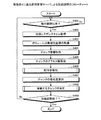
次に、図25を参照して、本実施例に係る運用管理サーバによる移動するチャンクの決定の流れにつて説明する。図25は、実施例4に係る運用管理サーバによる移動するチャンクの決定処理のフローチャートである。図25のフローチャートは、図24のフローチャートのステップS408の一例にあたる。 Next, with reference to FIG. 25, the flow of determining the chunk to be moved by the operation management server according to the present embodiment will be described. FIG. 25 is a flowchart of the process of determining the chunk to be moved by the operation management server according to the fourth embodiment. The flowchart in FIG. 25 corresponds to an example of step S408 in the flowchart in FIG.
配分率管理部102は、時間の計測を開始する(ステップS501)。
The distribution
次に、配分率管理部102は、最も優先度が高いチャンクを1つ取得する(ステップS502)。
Next, the distribution
次に、配分率管理部102は、数式13を用いて移動チャンクリストに記載されているチャンクを移動した場合の平均劣化率を計算する(ステップS503)。
Next, the distribution
そして、配分率管理部102は、算出した平均劣化率が平均劣化率の設定値未満か否かを判定する(ステップS504)。算出した平均劣化率が設定値以上の場合(ステップS504:否定)、配分率管理部102は、ステップS507へ進む。
Then, the distribution
これに対して、算出した平均劣化率が平均劣化率の設定値以下の場合(ステップS504:肯定)配分率管理部102は、チャンクリストに選択したチャンクを追加する(ステップS505)。
On the other hand, when the calculated average deterioration rate is equal to or less than the set value of the average deterioration rate (step S504: Yes), the distribution
次に、配分率管理部102は、移動するチャンクがあるか否かを判定する(ステップS506)。ここで、配分率管理部102は、チャンクリストに記載されたチャンクの数が、設定されている一定数を超えたか否かにより移動するチャンクの有無を判定する。移動するチャンクがある場合(ステップS506:肯定)、配分率管理部102は、ステップS502に戻る。
Next, the distribution
これに対して、移動するチャンクがない場合(ステップS506:否定)、配分率管理部102は、チャンクリストに記載されたチャンクを移動する指示を性能調整部252に通知する(ステップS507)。
On the other hand, when there is no chunk to be moved (No at Step S506), the allocation
その後、配分率管理部102は、計測している時間から一定時間が経過したか否かを判定する(ステップS508)。一定時間が経過していない場合(ステップS508:否定)、配分率管理部102は、ステップS502に戻る。これに対して、一定時間が経過した場合(ステップS508:肯定)、配分率管理部102は、処理を終了する。
Thereafter, the distribution
以上に説明したように本実施例に係るストレージ管理装置は、移動の優先度の高いチャンクから一定個数のチャンクを移動する処理を1回の性能調整として、その性能調整の処理を繰り返す。これにより、ディスクアクセスに起因する過度な性能劣化を防ぐことができる。また、性能調整にかかる時間を短縮することができ、業務負荷の急激な変動に対応することができる。 As described above, the storage management apparatus according to the present embodiment repeats the performance adjustment process, with the process of moving a certain number of chunks from chunks with high movement priority as one performance adjustment. Thereby, it is possible to prevent excessive performance deterioration due to disk access. In addition, the time required for performance adjustment can be shortened, and a sudden change in business load can be dealt with.
次に、実施例5について説明する。本実施例に係るストレージシステムは、QoS機能と自動階層化機能とが併用されている。図26は、実施例5に係る運用管理サーバ及びストレージ装置のブロック図である。本実施例に係る運用管理サーバ1は、帯域幅管理部105を有している。以下の説明では、実施例1と同様の各部の機能については説明を省略する。
Next, Example 5 will be described. The storage system according to the present embodiment uses both the QoS function and the automatic tiering function. FIG. 26 is a block diagram of the operation management server and the storage apparatus according to the fifth embodiment. The
記憶部104は、設定テーブル141、ボリュームテーブル142、ボリューム性能情報ファイル143及びリソース性能情報ファイル144を所定の情報記憶領域に記憶している。記憶部104の管理情報記憶領域は、各テーブルをテーブル化するための情報を記憶しておき、制御時にテーブル化して使用するようにしてもよい。
The
設定テーブル141は、ボリューム232の識別情報に対応させて、目標値、現在の帯域幅及び現在の配分率が登録されている。
In the setting table 141, the target value, the current bandwidth, and the current distribution rate are registered in association with the identification information of the
ボリュームテーブル142は、ボリューム232の識別情報に対応させて、RAIDの構成情報、ボリューム232が使用するCPUやスイッチなどのリソースの情報が登録されている。
In the volume table 142, RAID configuration information and resource information such as CPUs and switches used by the
ボリューム性能情報ファイル143には、ボリューム232の識別情報に対応させて、計測日時、ボリューム232の実測レスポンスタイム、実測IOPS及び実測スループットなどのボリューム性能情報が格納されている。
The volume performance information file 143 stores volume performance information such as measurement date and time, measured response time of the
リソース性能情報ファイル144には、測定を行った性能測定日時と共に、リソース種別、リソース識別情報及びビジー率が対応付けられて登録されている。
In the resource
帯域幅管理部105は、例えば、以下に説明する方法で各ボリューム232の帯域幅の管理を行う。
For example, the
帯域幅管理部105は、目標設定ボリュームが使用するリソースをボリューム性能情報ファイル143から取得する。そして、帯域幅管理部105は、リソース性能情報ファイル144を用いて、取得したリソースの中で最もビジー率の高いリソースを特定する。そして、帯域幅管理部105は、特定したリソースを使用しているボリューム232をボリューム性能情報ファイル143から選択する。そして、帯域幅管理部105は、選択したボリュームの中の目標設定ボリュームのうち実測性能値が目標性能値に達していない場合、当該ボリュームの帯域幅を広げる予約をする。また、帯域幅管理部105は、選択したボリュームの中の目標設定ボリュームのうち実測性能値が目標性能値に達していない場合、当該ボリュームの帯域幅を狭める予約をする。さらに、帯域幅管理部105は、目標設定ボリュームの帯域幅の調整に応じて、目標性能値が設定されていないボリューム232の帯域幅を変更を予約してもよい。
The
そして、帯域幅管理部105は、帯域幅の拡大及び縮小の予約を用いて各目標設定ボリューム及び目標が設定されていないボリューム232の帯域幅の拡大及び縮小を決定して、決定した帯域幅を性能調整部252に通知する。
Then, the
帯域幅管理部105の機能も、例えば、図2のCPU13及びメモリ12で実現される。例えば、HDD14に、帯域幅管理部105の機能を実現するための各種プログラムが格納される。そして、CPU13は、HDD14から各種プログラムを読み出し、帯域幅管理部105の機能を実現するプロセスをメモリ12上に展開して実行する。
The function of the
性能調整部252は、配分率管理部102から指定された配分率にしたがい、各ボリューム232のディスク203の種類毎の配分率の調整を行う。また、性能調整部252は、帯域幅管理部105からの帯域幅の調整の指示にしたがい、各ボリューム232の帯域幅の調整を行う。
The
ここで、配分率管理部102による性能調整と帯域幅管理部105による性能調整の実施タイミングについて説明する。
Here, the execution timing of the performance adjustment by the distribution
QoS機能による性能調整の収束速度は、自動階層化機能による性能調整に比べて早い。そこで、本実施例では、先に帯域幅管理部105が、QoS機能を用いた帯域幅の調整による性能調整を行う。その後、帯域幅管理部105のQoS機能による性能調整が限界に達した場合、配分率管理部102が、自動階層化機能を用いたディスク203の種類毎の配分率の変更による性能調整を実施する。そこで、図27を参照して、帯域幅管理部105及び配分率管理部102の動作タイミングについて詳細に説明する。図27は、QoS機能及び自動階層化機能の動作タイミングを表す図である。図27の縦軸はレスポンスタイムを表し、横軸は時間を表している。
The convergence speed of the performance adjustment by the QoS function is faster than the performance adjustment by the automatic tiering function. Therefore, in the present embodiment, the
図27の時間の開始時点は、性能調整の開始タイミングを表している。性能調整が開始すると、まず、帯域幅管理部105が、QoS機能による性能調整を行う。帯域幅管理部105は、QoS機能による性能調整の限界まで調整を行う。区間P1が、QoS機能による性能調整限界の範囲を表している。すなわち、帯域幅管理部105は、QoS機能による性能調整の限界に達する時間T1でQoS機能による性能調整を行う。
The time start point in FIG. 27 represents the start timing of performance adjustment. When the performance adjustment starts, first, the
その後、帯域幅管理部105は、性能調整終了の通知を配分率管理部102に通知する。
Thereafter, the
配分率管理部102は、実測レスポンスタイムと目標レスポンスタイムとを比較し、実測レスポンスタイムが目標レスポンスタイムに達していなければ、自動階層化機能による性能調整を実施する。区間P2が、自動階層化機能による性能調整限界の範囲を示している。そして、配分率管理部102は、時間T2をかけてレスポンスタイムが性能目標P3になるまで自動階層化機能による性能調整を行う。
The distribution
以上に説明したように、本実施例に係るストレージ管理装置は、同じ性能指標を用いてQoS機能及び自動階層化機能による性能調整を行う。QoS機能と自動階層化機能とを併用して性能調整の幅を広げる際に、利用者は容易に目標性能の設定を行うことができ、より柔軟で効果的な性能調整を行うことができる。 As described above, the storage management apparatus according to the present embodiment performs performance adjustment by the QoS function and the automatic tiering function using the same performance index. When expanding the range of performance adjustment by using both the QoS function and the automatic tiering function, the user can easily set the target performance, and can perform more flexible and effective performance adjustment.
さらに、QoS機能による性能調整の後に自動階層化機能による性能調整を行うことで、性能調整の効率を向上させることができる。 Furthermore, by performing performance adjustment by the automatic tiering function after performance adjustment by the QoS function, the efficiency of performance adjustment can be improved.
(変形例)
本変形例では、QoS機能による性能調整中に自動階層化機能による性能調整を実施し、さらに、自動階層化機能による性能調整の間に再度QoS機能の調整を行うことが実施例5と異なる。
(Modification)
This modification differs from the fifth embodiment in that the performance adjustment by the automatic tiering function is performed during the performance adjustment by the QoS function, and the QoS function is adjusted again during the performance adjustment by the automatic tiering function.
図28を参照して、本変形例に係る帯域幅管理部105及び配分率管理部102の動作タイミングについて詳細に説明する。図28は、QoS機能及び自動階層化機能の動作タイミングの他の例を表す図である。図28の縦軸はレスポンスタイムを表し、横軸は時間を表している。
With reference to FIG. 28, the operation timings of the
帯域幅管理部105は、QoS機能による性能調整を時間T3の間行う。
The
所定回数のQoS機能による性能調整が終わると、配分率管理部102は、自動階層化機能による性能調整を開始し、時間T4の間性能調整を実施する。
When the performance adjustment by the QoS function for a predetermined number of times is completed, the distribution
さらに、帯域幅管理部105は、QoS機能による性能調整を時間T5の間行い、QoS機能による性能調整の限界まで調整を行う。
Furthermore, the
その後、配分率管理部102は、性能目標に達するまで自動階層化機能による性能調整を時間T6の間行う。
Thereafter, the distribution
ここで、本変形例では、自動階層化機能による性能調整の間に、QoS機能による性能調整を1回挟んでいるが、この回数に特に制限はない。 Here, in this modification, the performance adjustment by the QoS function is sandwiched once between the performance adjustments by the automatic hierarchization function, but this number of times is not particularly limited.
以上に説明したように、本変形例に係るストレージ管理装置は、自動階層化機能による性能調整の間にQoS機能による性能調整を挟んで性能調整を行う。これにより、目標性能への収束は遅くなるが、QoS機能によりボリューム間での帯域幅の融通を適切に行うことができ、システム全体での最適化が可能となる。 As described above, the storage management apparatus according to the present modification performs performance adjustment by interposing performance adjustment by the QoS function between performance adjustment by the automatic tiering function. As a result, convergence to the target performance is delayed, but the bandwidth can be appropriately exchanged between the volumes by the QoS function, and optimization in the entire system becomes possible.
次に、実施例6について説明する。本実施例に係るストレージシステムは、QoS機能と自動階層化機能とが併用されており、さらに、自動階層化機能によりチャンク単位での性能調整を行う場合、QoS機能と併用する場合とは異なる領域を用いて調整を行う。本実施例に係る運用管理サーバ1及びストレージ装置2も、図26のブロック図で表される。以下の説明では、実施例5と同様の各部の機能については説明を省略する。
Next, Example 6 will be described. In the storage system according to the present embodiment, the QoS function and the automatic tiering function are used together. Further, when performance adjustment is performed in units of chunks using the automatic tiering function, an area different from the case where the QoS function is used together. Use to adjust. The
配分率管理部102は、チャンク単位での性能調整を指定された場合、ボリュームテーブル142を参照して目的性能値が設定されているボリューム232を特定する。配分率管理部102は、チャンク単位での性能調整を行う場合、最大IOPSを含むポリシー設定を受信する。
When the performance adjustment in units of chunks is designated, the distribution
そして、配分率管理部102は、目的性能が設定されているボリューム232以外のボリューム232を用いてチャンク単位での性能調整を、受信したポリシー設定に従い行う。
Then, the distribution
また、配分率管理部102は、容量の少ないディスク203の空き容量の枯渇を回避するため、ボリューム指定及びポリシー設定のための各ディスク203の使用量の割合の設定を記憶する。そして、配分率管理部102は、指定されたディスク203の使用量の割合に従い性能調整を行う。このボリューム指定及びポリシー設定によるディスク203の種類毎の配分率は、予め初期値が設定されており、運用中に操作者が設定しなおすようにしてもよい。
Further, the distribution
これにより、従来の自動階層化機能によるポリシー設定を利用したチャンク単位の最適化の効果も得ることができる。ただし、QoS機能と自動最適化機能との連携における収束速度は速い方が好ましく、ポリシー設定による最適化のディスク領域を設けなくてもよい。 Thereby, the optimization effect of the chunk unit using the policy setting by the conventional automatic hierarchization function can also be obtained. However, it is preferable that the convergence speed in cooperation between the QoS function and the automatic optimization function is fast, and it is not necessary to provide a disk area for optimization by policy setting.
さらに、QoS機能と自動最適化機能との連携による性能調整において使用するディスク使用量の割合を適用する場合、配分率管理部102は、以下のような処理を行う。配分率管理部102は、チャンク移動時に、各ディスク203の空き容量に指定された割合を乗算した上で空き容量の確認を行い、空き容量が不足した場合はチャンク移動を実行しない。これにより、各ディスク203に対する使用量を一律に減らすことができる。
Furthermore, when applying the ratio of disk usage used in performance adjustment by cooperation between the QoS function and the automatic optimization function, the distribution
次に、実施例7について説明する。本実施例に係るストレージシステムは、QoS機能及び自動階層化機能が併用され、且つ、性能目標が目標レベルとして設定される。本実施例に係る運用管理サーバ1及びストレージ装置2も図26のブロック図で表される。以下の説明では、実施例5と同様の各部の機能については説明を省略する。
Next, Example 7 will be described. In the storage system according to this embodiment, the QoS function and the automatic tiering function are used together, and the performance target is set as the target level. The
設定部101は、操作端末3より、目標性能レベルとして、目標設定ボリューム毎に高性能、中性能又は低性能の入力を受ける。そして、設定部101は、受信した性能レベルを設定テーブル141に書き込む。
The
配分率管理部102は、例えば、図29の配分率重み対応表191のように、レベル毎にそれぞれのディスク203の種類毎の重みを記憶している。図29は、配分率重み対応表の一例の図である。
The distribution
ここで、配分率管理部102は、設定テーブル141から目標性能レベルを取得する。そして、配分率管理部102は、目標設定レベルに対応する目標値を算出する。ここで、配分率管理部102は、各レベルに対応する目標値を予め記憶しておいてもよいし、各ボリューム性能情報を用いて目標値を算出してもよい。ただし、配分率管理部102が用いる目標値と、帯域幅管理部105が用いる目標値とは同じものを用いる。
Here, the distribution
配分率管理部102は、目標レスポンスタイムが実測レスポンスタイムより小さく、且つ、帯域幅管理部105による帯域調整によって帯域制限幅が最も広くなっているか又は帯域制限が行われていない場合、以下の処理をおこなう。すなわち、配分率管理部102は、目標設定ボリュームに高速ディスクを多く割り当てるように配分率を変更する。
When the target response time is smaller than the actually measured response time and the bandwidth limitation width is the widest by the bandwidth adjustment by the
また、配分率管理部102は、目標レスポンスタイムが実測レスポンスタイムより大きく、且つ、帯域幅管理部105による帯域調整によって帯域制限幅が最も狭くなっている場合、以下の処理をおこなう。すなわち、配分率管理部102は、目標設定ボリュームに低速ディスクを多く割り当てるように配分率を変更する。
Further, when the target response time is larger than the actually measured response time and the bandwidth limit width is narrowed by the bandwidth adjustment by the
具体的には、配分率管理部102は、以下の方法で配分を行う。以下では、一例として、高性能とされたボリューム232の合計が100GB、中性能とされたボリューム232の合計が200GB、低性能とされたボリューム232の合計が300GBである場合で説明する。
Specifically, the distribution
配分率管理部102は、各レベルに応じたボリューム232の容量に配分率重み対応表の値を乗算して合計することで、各種類のディスク203に対する、重みを加えた全体の容量を算出する。例えば、高速ディスクであれば、重みを加えた全体の容量は、2×100GB+1×200GB+0.5×300GB=550GBと算出できる。
The distribution
そして、重みを加えた全体の容量を、重みに従って配分する。すなわち、配分率管理部102は、高性能とされたボリューム232に割り当てる高速ディスクを、(100GB×2×100GB)/550GB=36GBと算出する。また、配分率管理部102は、中性能とされたボリューム232に割り当てる高速ディスクを、(100GB×1×200GB)/550GB=36GBと算出する。さらに、配分率管理部102は、低性能とされたボリューム232に割り当てる高速ディスクを、(100GB×0.5×300GB)/550GB=27GBと算出する。
Then, the entire capacity to which the weight is added is distributed according to the weight. That is, the distribution
配分率管理部102は、中速ディスクに対しても同様に、各レベルのボリューム232に対する配分率を決定する。さらに、配分率管理部102は、各レベルのボリューム232の高速ディスク及び中速ディスクを割り当てた残余に低速ディスクを割り当てる。
Similarly, the distribution
この配分率により目標レスポンスタイムを達成できない場合、配分率管理部102は、上記実施例で説明した配分率の決定を行う。
When the target response time cannot be achieved by this distribution rate, the distribution
さらに、以上の各実施例では、性能指標としてレスポンスタイムを主に使用して説明したが、性能指標はこれに限らず、例えば、IOPSやスループットを用いてもよい。その場合も、ストレージ管理装置は同様の機能及び効果を有する。 Further, in each of the above embodiments, the response time is mainly used as the performance index. However, the performance index is not limited to this, and for example, IOPS or throughput may be used. Even in this case, the storage management apparatus has the same functions and effects.
以上の各実施例を含む実施形態に関し、さらに以下の付記を開示する。 The following supplementary notes are further disclosed with respect to the embodiments including the above examples.
(付記1)性能の異なる複数種類の記憶部を有するストレージ装置を管理するストレージ管理装置であって、
異なる種類の前記記憶部を用いて生成された記憶領域に対して性能の目標値を設定する設定部と、
前記設定部により設定された目標値に基づいて、前記記憶領域に含まれる前記記憶部の前記種類毎の配分率を決定し、決定した前記配分率での前記記憶領域の再生成を前記ストレージ装置に指示する配分率管理部と
を備えたことを特徴とするストレージ管理装置。
(Supplementary note 1) A storage management device for managing a storage device having a plurality of types of storage units having different performances,
A setting unit that sets a target value of performance for storage areas generated using different types of the storage units;
Based on the target value set by the setting unit, a distribution rate for each type of the storage unit included in the storage region is determined, and the storage device is regenerated at the determined distribution rate. A storage management apparatus comprising: a distribution rate management unit that instructs
(付記2)前記配分率管理部は、前記記憶領域の性能の予測値を求める近似式を生成し、前記近似式を用いて算出した前記予測値が前記目標値により近くなるように前記配分率を決定することを特徴とする付記1に記載のストレージ管理装置。
(Additional remark 2) The said allocation rate management part produces | generates the approximate expression which calculates | requires the predicted value of the performance of the said storage area, and the said allocation rate is calculated so that the said predicted value calculated using the said approximate expression may become near the said target value The storage management device according to
(付記3)前記配分率管理部は、前記記憶部の前記種類毎の性能、及び格納するデータに対するアクセスの頻度を表すアクセス分布関数を求め、前記記憶部の種類毎の性能及び前記アクセス分布関数を基に前記近似式を求めることを特徴とする付記2に記載のストレージ管理装置。
(Additional remark 3) The said allocation rate management part calculates | requires the access distribution function showing the frequency for every said kind of the said memory | storage part, and the access frequency with respect to the data to store, the performance for every kind of the said memory | storage part, and the said access distribution function The storage management apparatus according to
(付記4)前記配分率管理部は、予め与えられている前記記憶部の前記種類毎の性能の固定値を、予め決められた前記アクセス分布関数に使用することを特徴とする付記3に記載のストレージ管理装置。
(Additional remark 4) The said allocation rate management part uses the fixed value of the performance for every said kind of the said memory | storage part given to the said predetermined access distribution function, The
(付記5)前記配分率管理部は、前記記憶部の性能及びアクセス頻度の計測値を取得し、前記アクセス頻度の計測値を用いて各前記記憶部の種類毎の前記アクセス分布関数を算出することを特徴とする付記3に記載のストレージ管理装置。
(Additional remark 5) The said distribution rate management part acquires the measured value of the performance and access frequency of the said memory | storage part, and calculates the said access distribution function for every kind of each said memory | storage part using the measured value of the said access frequency The storage management device according to
(付記6)前記配分率管理部は、前記記憶領域の性能を計測し、計測した値が前記目標値に近づくように前記配分率を変更していくことを特徴とする付記1に記載のストレージ管理装置。
(Supplementary note 6) The storage according to
(付記7)前記目標値に基づいて前記記憶領域の帯域幅を調整する帯域幅管理部をさらに備えたことを特徴とする付記1〜6のいずれか一つに記載のストレージ管理装置。
(Supplementary note 7) The storage management device according to any one of
(付記8)前記記憶領域に対する1回の性能調整において、前記配分率管理部は、前記帯域幅管理部による帯域幅の調整後に、前記記憶部の前記種類毎の前記配分率の変更を実施することを特徴とする付記7に記載のストレージ管理装置。
(Additional remark 8) In one performance adjustment with respect to the said storage area, the said allocation rate management part implements the change of the said allocation rate for every said type of the said memory | storage part after the bandwidth adjustment by the said bandwidth management part. Item 8. The storage management device according to
(付記9)前記記憶領域に対する1回の性能調整において、前記帯域幅管理部による帯域幅の調整と、前記配分率管理部による前記記憶部の前記種類毎の前記配分率の変更とを繰り返して前記目標値に前記記憶領域の性能を近づけることを特徴とする付記7に記載のストレージ管理装置。
(Supplementary note 9) In one performance adjustment for the storage area, the bandwidth management unit adjusts the bandwidth and the distribution rate management unit changes the distribution rate for each type of the storage unit. The storage management device according to
(付記10)前記設定部は、前記記憶領域に対する性能レベルの指定の入力を受信して、前記記憶領域に対する性能の目標値として設定し、
前記配分率管理部は、入力された前記性能レベルに応じて前記記憶領域に対するデータの入出力の性能の目標値を求める
ことを特徴とする付記1〜9のいずれか一つに記載のストレージ管理装置。
(Additional remark 10) The said setting part receives the designation | designated input of the performance level with respect to the said storage area, sets it as the target value of the performance with respect to the said storage area,
The storage management according to any one of
(付記11)前記配分率管理部は、前記種類毎に、前記性能レベル毎の調整値を予め記憶しており、前記調整値を基に前記記憶部の前記種類毎の前記配分率を決定し、決定した配分率で生成された前記記憶領域の性能が前記目標値に達しない場合に、前記目標値に基づく前記配分率の決定を実行することを特徴とする付記1〜10のいずれか一つに記載のストレージ管理装置。
(Additional remark 11) The said allocation rate management part has previously memorize | stored the adjustment value for every said performance level for every said type, and determines the said allocation rate for every said type of the said memory | storage part based on the said adjustment value. Any one of
(付記12)性能の異なる複数種類の記憶部を有するストレージ装置の性能調整方法であって、
異なる種類の前記記憶部を用いて生成された記憶領域に対して性能の目標値を設定し、
前記目標値に基づいて、前記記憶領域に含まれる前記記憶部の前記種類毎の配分率を決定し、
決定した前記配分率での前記記憶領域の再生成を前記ストレージ装置に指示する
ことを特徴とする性能調整方法。
(Supplementary note 12) A method for adjusting the performance of a storage apparatus having a plurality of types of storage units with different performances,
Set performance target values for storage areas generated using different types of storage units,
Based on the target value, determine a distribution rate for each type of the storage unit included in the storage area,
Instructing the storage apparatus to regenerate the storage area at the determined allocation rate.
(付記13)性能の異なる複数種類の記憶部を有するストレージ装置の性能調整プログラムであって、
異なる種類の前記記憶部を用いて生成された記憶領域に対して性能の目標値を設定し、
前記目標値に基づいて、前記記憶領域に含まれる前記記憶部の前記種類毎の配分率を決定し、
決定した前記配分率での前記記憶領域の再生成を前記ストレージ装置に指示する
処理をコンピュータに実行させることを特徴とする性能調整プログラム。
(Supplementary note 13) A performance adjustment program for a storage apparatus having a plurality of types of storage units with different performances,
Set performance target values for storage areas generated using different types of storage units,
Based on the target value, determine a distribution rate for each type of the storage unit included in the storage area,
A performance adjustment program for causing a computer to execute a process of instructing the storage apparatus to regenerate the storage area at the determined allocation rate.
1 運用管理サーバ
2 ストレージ装置
3 操作端末
4 業務サーバ
11 NIC
12 メモリ
13 CPU
14 HDD
21,22 ストレージ装置
41,42 業務サーバ
51,52 FCスイッチ
61,62 ネットワークスイッチ
101 設定部
102 配分率管理部
103 監視部
104 記憶部
105 帯域幅管理部
141 設定テーブル
142 ボリュームテーブル
143 ボリューム性能情報ファイル
144 リソース性能情報ファイル
145 チャンク構成情報
201,202 CM
203 ディスク
211 FC−CA
212 iSCSI−CA
213 CPU
214 メモリ
215 NIC
216 SAS
231 RAIDグループ
232 ボリューム
251 処理実行部
252 性能調整部
253 性能情報取得部
1
12
14 HDD
21, 22
203
212 iSCSI-CA
213 CPU
214
216 SAS
231
Claims (10)
異なる種類の前記記憶部を用いて生成された記憶領域に対して性能の目標値を設定する設定部と、
前記設定部により設定された目標値に基づいて、前記記憶領域に含まれる前記記憶部の全体の数に対する前記種類毎の個数を表す配分率を決定し、決定した前記配分率での前記記憶領域の再生成を前記ストレージ装置に指示する配分率管理部と
を備えたことを特徴とするストレージ管理装置。 A storage management device that manages storage devices having a plurality of types of storage units with different performances,
A setting unit that sets a target value of performance for storage areas generated using different types of the storage units;
Based on the target value set by the setting unit , a distribution rate representing the number of each type with respect to the total number of the storage units included in the storage region is determined, and the storage region at the determined distribution rate A storage management device comprising: a distribution ratio management unit that instructs the storage device to regenerate the storage device.
前記配分率管理部は、入力された前記性能レベルに応じて前記記憶領域に対するデータの入出力の性能の目標値を求める
ことを特徴とする請求項1〜6のいずれか一つに記載のストレージ管理装置。 The setting unit receives an input for specifying a performance level for the storage area, and sets it as a performance target value for the storage area.
The storage according to any one of claims 1 to 6, wherein the allocation rate management unit obtains a target value of data input / output performance for the storage area according to the input performance level. Management device.
異なる種類の前記記憶部を用いて生成された記憶領域に対して性能の目標値を設定し、
前記目標値に基づいて、前記記憶領域に含まれる前記記憶部の全体の数に対する前記種類毎の個数を表す配分率を決定し、
決定した前記配分率での前記記憶領域の再生成を前記ストレージ装置に指示する
ことを特徴とする性能調整方法。 A performance adjustment method for a storage device having a plurality of types of storage units with different performances,
Set performance target values for storage areas generated using different types of storage units,
Based on the target value, determine a distribution ratio representing the number of each type relative to the total number of the storage units included in the storage area,
Instructing the storage apparatus to regenerate the storage area at the determined allocation rate.
異なる種類の前記記憶部を用いて生成された記憶領域に対して性能の目標値を設定し、
前記目標値に基づいて、前記記憶領域に含まれる前記記憶部の全体の数に対する前記種類毎の個数を表す配分率を決定し、
決定した前記配分率での前記記憶領域の再生成を前記ストレージ装置に指示する
処理をコンピュータに実行させることを特徴とする性能調整プログラム。 A performance adjustment program for a storage device having a plurality of types of storage units with different performances,
Set performance target values for storage areas generated using different types of storage units,
Based on the target value, determine a distribution ratio representing the number of each type relative to the total number of the storage units included in the storage area,
A performance adjustment program for causing a computer to execute a process of instructing the storage apparatus to regenerate the storage area at the determined allocation rate.
Priority Applications (3)
| Application Number | Priority Date | Filing Date | Title |
|---|---|---|---|
| JP2014070511A JP6260407B2 (en) | 2014-03-28 | 2014-03-28 | Storage management device, performance adjustment method, and performance adjustment program |
| EP15155939.0A EP2924554A1 (en) | 2014-03-28 | 2015-02-20 | Storage management apparatus, performance adjusting method, and performance adjusting program |
| US14/632,425 US9606735B2 (en) | 2014-03-28 | 2015-02-26 | Storage management apparatus, and performance adjusting method |
Applications Claiming Priority (1)
| Application Number | Priority Date | Filing Date | Title |
|---|---|---|---|
| JP2014070511A JP6260407B2 (en) | 2014-03-28 | 2014-03-28 | Storage management device, performance adjustment method, and performance adjustment program |
Publications (2)
| Publication Number | Publication Date |
|---|---|
| JP2015191628A JP2015191628A (en) | 2015-11-02 |
| JP6260407B2 true JP6260407B2 (en) | 2018-01-17 |
Family
ID=52544353
Family Applications (1)
| Application Number | Title | Priority Date | Filing Date |
|---|---|---|---|
| JP2014070511A Active JP6260407B2 (en) | 2014-03-28 | 2014-03-28 | Storage management device, performance adjustment method, and performance adjustment program |
Country Status (3)
| Country | Link |
|---|---|
| US (1) | US9606735B2 (en) |
| EP (1) | EP2924554A1 (en) |
| JP (1) | JP6260407B2 (en) |
Families Citing this family (14)
| Publication number | Priority date | Publication date | Assignee | Title |
|---|---|---|---|---|
| JP6179321B2 (en) * | 2013-09-27 | 2017-08-16 | 富士通株式会社 | Storage management device, control method, and control program |
| JP6033985B2 (en) * | 2014-03-07 | 2016-11-30 | 株式会社日立製作所 | Performance evaluation method and information processing apparatus |
| JP6273966B2 (en) | 2014-03-27 | 2018-02-07 | 富士通株式会社 | Storage management device, performance adjustment method, and performance adjustment program |
| JP6253752B1 (en) | 2016-11-29 | 2017-12-27 | 株式会社東芝 | Tiered storage system |
| US10521444B2 (en) * | 2016-12-21 | 2019-12-31 | Sap Se | Data retrieval based on field size |
| US10915361B1 (en) * | 2018-04-30 | 2021-02-09 | Amazon Technologies, Inc. | Dynamic capacity buffers |
| US10963172B2 (en) * | 2018-08-09 | 2021-03-30 | Apple Inc. | Systems and methods for providing a back pressure free interconnect |
| JP7163672B2 (en) * | 2018-08-30 | 2022-11-01 | 富士通株式会社 | Storage management device, performance adjustment method and performance adjustment program |
| CN113126889A (en) * | 2020-01-15 | 2021-07-16 | 伊姆西Ip控股有限责任公司 | Method, apparatus and computer program product for managing storage space |
| US11546420B2 (en) | 2020-02-24 | 2023-01-03 | Netapp, Inc. | Quality of service (QoS) settings of volumes in a distributed storage system |
| US11005924B1 (en) * | 2020-04-01 | 2021-05-11 | Netapp, Inc. | Disparity of quality of service (QoS) settings of volumes across a cluster |
| US11140219B1 (en) | 2020-04-07 | 2021-10-05 | Netapp, Inc. | Quality of service (QoS) setting recommendations for volumes across a cluster |
| US11693563B2 (en) | 2021-04-22 | 2023-07-04 | Netapp, Inc. | Automated tuning of a quality of service setting for a distributed storage system based on internal monitoring |
| CN117312328B (en) * | 2023-11-28 | 2024-03-01 | 金篆信科有限责任公司 | Self-adaptive bottom storage configuration method, device, system and medium |
Family Cites Families (21)
| Publication number | Priority date | Publication date | Assignee | Title |
|---|---|---|---|---|
| JP3641872B2 (en) * | 1996-04-08 | 2005-04-27 | 株式会社日立製作所 | Storage system |
| JP4325843B2 (en) * | 2002-12-20 | 2009-09-02 | 株式会社日立製作所 | Logical volume copy destination performance adjustment method and apparatus |
| KR100749298B1 (en) * | 2003-08-06 | 2007-08-14 | 마쯔시다덴기산교 가부시키가이샤 | Semiconductor memory card, and accessing device and method |
| JP4244319B2 (en) * | 2003-12-17 | 2009-03-25 | 株式会社日立製作所 | Computer system management program, recording medium, computer system management system, management device and storage device therefor |
| JP4715286B2 (en) * | 2004-05-11 | 2011-07-06 | 株式会社日立製作所 | Computer system and computer system control method |
| JP4420351B2 (en) * | 2005-09-30 | 2010-02-24 | 富士通株式会社 | Hierarchical storage system, control method and program |
| US20070294314A1 (en) * | 2006-06-16 | 2007-12-20 | Michael Padovano | Bitmap based synchronization |
| JP4887955B2 (en) | 2006-07-21 | 2012-02-29 | 日本電気株式会社 | Data allocation management system, method and program |
| JP4809413B2 (en) * | 2008-10-08 | 2011-11-09 | 株式会社日立製作所 | Storage system |
| US20100100677A1 (en) | 2008-10-16 | 2010-04-22 | Mckean Brian | Power and performance management using MAIDx and adaptive data placement |
| US8874867B2 (en) | 2008-11-21 | 2014-10-28 | Lsi Corporation | Identification and containment of performance hot-spots in virtual volumes |
| US8239632B2 (en) * | 2009-03-12 | 2012-08-07 | At&T Mobility Ii Llc | Data caching in consolidated network repository |
| US8566550B2 (en) | 2009-09-22 | 2013-10-22 | Hitachi, Ltd. | Application and tier configuration management in dynamic page reallocation storage system |
| US8135928B2 (en) * | 2009-10-26 | 2012-03-13 | Symantec Operating Corporation | Self-adjusting change tracking for fast resynchronization |
| US8560799B2 (en) * | 2010-02-18 | 2013-10-15 | Hitachi, Ltd. | Performance management method for virtual volumes |
| US9934108B2 (en) * | 2010-10-27 | 2018-04-03 | Veritas Technologies Llc | System and method for optimizing mirror creation |
| WO2012168967A1 (en) * | 2011-06-07 | 2012-12-13 | Hitachi, Ltd. | Storage apparatus and data management method |
| US8856440B2 (en) * | 2011-09-12 | 2014-10-07 | Microsoft Corporation | Volatile memory representation of nonvolatile storage device set |
| JP2013164822A (en) | 2012-02-13 | 2013-08-22 | Fujitsu Ltd | Load threshold value calculating program, load threshold value calculating device, and load threshold value calculating method |
| WO2013136366A1 (en) * | 2012-03-14 | 2013-09-19 | Hitachi, Ltd. | Storage apparatus and program update method |
| US9146853B2 (en) * | 2013-03-28 | 2015-09-29 | Microsoft Technology Licensing, Llc | Managing capacity of a thinly provisioned storage system |
-
2014
- 2014-03-28 JP JP2014070511A patent/JP6260407B2/en active Active
-
2015
- 2015-02-20 EP EP15155939.0A patent/EP2924554A1/en not_active Withdrawn
- 2015-02-26 US US14/632,425 patent/US9606735B2/en active Active
Also Published As
| Publication number | Publication date |
|---|---|
| JP2015191628A (en) | 2015-11-02 |
| US9606735B2 (en) | 2017-03-28 |
| US20150277767A1 (en) | 2015-10-01 |
| EP2924554A1 (en) | 2015-09-30 |
Similar Documents
| Publication | Publication Date | Title |
|---|---|---|
| JP6260407B2 (en) | Storage management device, performance adjustment method, and performance adjustment program | |
| US8943270B2 (en) | Storage system, storage control method and storage control program | |
| US10853139B2 (en) | Dynamic workload management based on predictive modeling and recommendation engine for storage systems | |
| JP5981563B2 (en) | Information storage system and method for controlling information storage system | |
| US8850152B2 (en) | Method of data migration and information storage system | |
| US8621178B1 (en) | Techniques for data storage array virtualization | |
| US9658779B2 (en) | Computer system and control method for computer system | |
| US8321646B2 (en) | Method and apparatus for rebalancing storage components within a storage tier | |
| US9626105B2 (en) | Controlling a storage system | |
| EP2854018B1 (en) | Storage management device, control method , and control program | |
| US20130036266A1 (en) | First storage control apparatus and storage system management method | |
| US10037162B2 (en) | Storage management device, storage management method, and computer-readable recording medium | |
| US10664182B2 (en) | Storage system | |
| CN108733308B (en) | Method and apparatus for managing disk pool | |
| US9836246B2 (en) | Storage management device, performance adjustment method, and computer-readable recording medium | |
| WO2011101909A1 (en) | Virtual volume control method and storage device | |
| US9734048B2 (en) | Storage management device, performance adjustment method, and computer-readable recording medium | |
| JP6394313B2 (en) | Storage management device, storage management method, and storage management program | |
| US11237745B2 (en) | Computer system and volume arrangement method in computer system to reduce resource imbalance | |
| CN110874192A (en) | Storage management apparatus and storage management method |
Legal Events
| Date | Code | Title | Description |
|---|---|---|---|
| A621 | Written request for application examination |
Free format text: JAPANESE INTERMEDIATE CODE: A621 Effective date: 20161206 |
|
| A977 | Report on retrieval |
Free format text: JAPANESE INTERMEDIATE CODE: A971007 Effective date: 20170823 |
|
| A131 | Notification of reasons for refusal |
Free format text: JAPANESE INTERMEDIATE CODE: A131 Effective date: 20170905 |
|
| A521 | Written amendment |
Free format text: JAPANESE INTERMEDIATE CODE: A523 Effective date: 20171030 |
|
| TRDD | Decision of grant or rejection written | ||
| A01 | Written decision to grant a patent or to grant a registration (utility model) |
Free format text: JAPANESE INTERMEDIATE CODE: A01 Effective date: 20171114 |
|
| A61 | First payment of annual fees (during grant procedure) |
Free format text: JAPANESE INTERMEDIATE CODE: A61 Effective date: 20171127 |
|
| R150 | Certificate of patent or registration of utility model |
Ref document number: 6260407 Country of ref document: JP Free format text: JAPANESE INTERMEDIATE CODE: R150 |