JP6257310B2 - Imaging apparatus, imaging control method, and program - Google Patents
Imaging apparatus, imaging control method, and program Download PDFInfo
- Publication number
- JP6257310B2 JP6257310B2 JP2013264081A JP2013264081A JP6257310B2 JP 6257310 B2 JP6257310 B2 JP 6257310B2 JP 2013264081 A JP2013264081 A JP 2013264081A JP 2013264081 A JP2013264081 A JP 2013264081A JP 6257310 B2 JP6257310 B2 JP 6257310B2
- Authority
- JP
- Japan
- Prior art keywords
- photographing
- image
- display
- instruction
- unit
- Prior art date
- Legal status (The legal status is an assumption and is not a legal conclusion. Google has not performed a legal analysis and makes no representation as to the accuracy of the status listed.)
- Expired - Fee Related
Links
Images


Landscapes
- Shutter-Related Mechanisms (AREA)
- Indication In Cameras, And Counting Of Exposures (AREA)
- Studio Devices (AREA)
- Cameras In General (AREA)
Description
本発明は、撮影装置、撮影制御方法及びプログラムに関する。 The present invention relates to a photographing apparatus, a photographing control method, and a program.
従来、携帯電話やスマートフォンのように、通常カメラ(以下、アウトカメラと称する)に加え、内側に向けられたカメラ(以下、インカメラと称する)を備えた電子機器が知られている。このような電子機器では、アウトカメラで被写体を、インカメラで撮影者の表情を撮影し、被写体を撮影したときの撮影者の表情を残すことができる。
インカメラを備える電子機器は、一度のレリーズ操作で、アウトカメラとインカメラのシャッターを同時に切ることができ、インカメラ及びアウトカメラの撮影画像を関連付けて記録することができる(特許文献1参照)。
2. Description of the Related Art Conventionally, an electronic device including a camera facing inward (hereinafter referred to as an in-camera) in addition to a normal camera (hereinafter referred to as an out-camera) is known, such as a mobile phone or a smartphone. In such an electronic device, the subject can be photographed with the out-camera, the photographer's facial expression with the in-camera, and the photographer's facial expression when the subject is photographed can be left.
An electronic device equipped with an in-camera can simultaneously release the shutters of the out-camera and the in-camera with a single release operation, and can record the images captured by the in-camera and the out-camera in association with each other (see Patent Document 1). .
しかしながら、従来技術においては、被写体撮影時の撮影者の表情を撮影することはできるものの、実際に撮影画像を見たときの撮影者の表情を残すことができないという問題があった。 However, the conventional technique has a problem that although the photographer's facial expression at the time of shooting the subject can be photographed, the photographer's facial expression when the photographed image is actually viewed cannot be left.
本発明はこのような問題点に鑑みなされたもので、撮影画像を見たときの撮影者の表情を記録することを目的とする。 The present invention has been made in view of such problems, and an object of the present invention is to record a photographer's facial expression when a photographed image is viewed.
そこで、本発明は、撮影装置であって、第1の撮影手段と、前記第1の撮影手段による画像の撮影指示を受け付ける指示手段と、前記第1の撮影手段により撮影した画像を表示する表示手段と、前記表示手段が設けられている側を撮影するための第2の撮影手段と、前記指示手段により撮影指示を受け付けたことに応じて前記第1の撮影手段により撮影した画像を前記表示手段に表示し、当該画像の表示中に前記第2の撮影手段により画像を撮影するように制御する制御手段とを有することを特徴とする。 Accordingly, the present invention provides a photographing apparatus, and displays the first imaging means, and instruction means for accepting an imaging instruction of the image by the first imaging means, an image photographed by the first photographing means display Means, a second photographing means for photographing the side provided with the display means, and the display of an image photographed by the first photographing means in response to accepting a photographing instruction by the instruction means And a control unit that controls to display an image by the second imaging unit while the image is displayed .
本発明によれば、撮影画像を見たときの撮影者の表情を記録することができる。 According to the present invention, it is possible to record the photographer's facial expression when viewing a photographed image.
以下、本発明の実施形態について図面に基づいて説明する。 Hereinafter, embodiments of the present invention will be described with reference to the drawings.
(第1の実施形態)
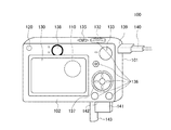
図1は、撮影装置の一例としてのデジタルカメラ100の外観図である。図1には、デジタルカメラ100の裏面側を示している。デジタルカメラ100は、主に被写体を撮影するアウトカメラ110と、撮影者を撮影することのできるインカメラ120とを備えている。
アウトカメラ110は、デジタルカメラ100の第1の主面101に設けられている。アウトカメラ110は、被写体を撮影する。インカメラ120は、第1の主面101と反対側の第2の主面102に設けられている。インカメラ120は、アウトカメラ110の撮影方向(光軸)と逆の撮影方向において撮影者等の撮影を行うことができる。第2の主面102には、表示部130が設けられており、インカメラ120は、表示部130が設けられている側を撮影する。なお、アウトカメラ110による撮影を、適宜アウトカメラ撮影と称し、インカメラ120による撮影を、適宜インカメラ撮影と称することとする。
(First embodiment)
FIG. 1 is an external view of a
The
表示部130は、画像や各種情報を表示する。シャッターボタン132は、撮影指示を行うための操作部である。モード切替スイッチ133は、デジタルカメラ100の動作モードを切り替えるための操作部である。電源スイッチ135は、電源のON/OFFを切り替える。操作部136は、ユーザからの各種操作を受け付ける各種スイッチ、ボタン等の操作部材を有している。コントローラホイール137は、操作部136に含まれる回転操作可能な操作部材である。
138は接眼ファインダである。接眼ファインダ138は、光学ファインダである。なお、他の例としては、接眼ファインダ138は、電子ビューファインダ(EVF)であってもよい。コネクタ139は、接続ケーブル140とデジタルカメラ100とのコネクタである。記録媒体141は、メモリカードやハードディスク等の記録媒体である。記録媒体141は、撮影された画像等を記録する。記録媒体スロット142は、記録媒体141を格納するためのスロットである。記録媒体スロット142に格納された記録媒体141は、デジタルカメラ100との通信が可能となる。蓋143は記録媒体スロット142の蓋である。
The
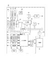
図2は、デジタルカメラ100を示すブロック図である。アウトカメラ110は、撮影レンズ111と、シャッター112と、撮像部113とを有している。撮影レンズ111は、ズームレンズ、フォーカスレンズを含むレンズ群である。シャッター112は、絞り機能を備えるシャッターである。撮像部113は、光学像を電気信号に変換するCCDやCMOS素子等で構成される撮像素子である。バリア150は、撮影レンズ111を含む撮像系を覆うことにより、撮影レンズ111、シャッター112、撮像部113を含む撮像系の汚れや破損を防止する。
インカメラ120は、アウトカメラ110と同様に、撮影レンズ121と、シャッター122と、撮像部123とを有している。撮影レンズ121、シャッター122及び撮像部123は、それぞれ撮影レンズ111、シャッター112及び撮像部113と同様である。
A/D変換器151は、アナログ信号をデジタル信号に変換する。A/D変換器151は、アウトカメラ110の撮像部113から出力される信号変換だけでなく、同時にインカメラ120の撮像部123から出力されるアナログ信号をデジタル信号に変換する。
FIG. 2 is a block diagram showing the
Similar to the
The A /
画像処理部152は、A/D変換器151から受け取ったデータ、又はメモリ制御部153から受け取ったデータに対し、所定の画素補間、縮小といったリサイズ処理や色変換処理を行う。画像処理部152はまた、撮影された画像データに対し、所定の演算処理を行う。
演算処理の結果は、システム制御部157により利用される。すなわち、システム制御部157は、演算結果に基づいて、露光制御や測距制御を行う。システム制御部157は、例えば、TTL(スルー・ザ・レンズ)方式のAF(オートフォーカス)処理、AE(自動露出)処理、EF(フラッシュプリ発光)処理、AWB(オートホワイトバランス)処理を行う。
The
The result of the arithmetic processing is used by the
A/D変換器151からの出力データは、画像処理部152及びメモリ制御部153を介して、或いは、メモリ制御部153を介してメモリ154に直接書き込まれる。メモリ154は、撮像部113,123によって得られ、A/D変換器151によりデジタルデータに変換された画像データや、表示部130に表示するための画像データを格納する。メモリ154は、所定枚数の静止画像や所定時間の動画像および音声を格納するのに十分な記憶容量を備えているものとする。また、メモリ154は、画像表示用のメモリ(ビデオメモリ)を兼ねている。
D/A変換器155は、メモリ154に格納されている画像表示用のデータをアナログ信号に変換して表示部130に供給する。こうして、メモリ154に書き込まれた表示用の画像データはD/A変換器155を介して表示部130により表示される。
表示部130は、LCD等の表示器上に、D/A変換器155からのアナログ信号に応じた表示を行う。不揮発性メモリ156は、電気的に消去・記録可能なメモリである。不揮発性メモリ156として、例えばEEPROM等が用いられる。不揮発性メモリ156には、システム制御部157の動作用の定数、プログラム等が記憶される。ここでいう、プログラムとは、本実施形態にて後述する各種フローチャートを実行するためのプログラムのことである。
Output data from the A /
The D /
The
システム制御部157は、例えばCPUであり、デジタルカメラ100全体を制御する。システム制御部157は、前述した不揮発性メモリ156に記録されたプログラムを実行することで、後述する本実施形態の各処理を実現する。システム制御部157は、例えばアウトカメラ110及びインカメラ120の撮影制御を行う。
システム制御部157はまた、メモリ154、D/A変換器155、表示部130等を制御することにより表示制御を行う。より具体的には、システム制御部157は、A/D変換器151によって一度A/D変換されメモリ154に蓄積されたデジタル信号をD/A変換器155においてアナログ変換し、表示部130に逐次転送して表示する。これにより、表示部130は、電子ビューファインダとして機能し、スルー画像を表示することができる。
システムメモリ158には、システム制御部157の動作用の定数、変数、不揮発性メモリ156から読み出したプログラム等を展開する。システムメモリ158には、例えばRAMが用いられる。システムタイマー159は、各種制御に用いる時間や、内蔵された時計の時間を計測する計時部である。
The
The
In the
モード切替スイッチ133、第1シャッタースイッチ161、第2シャッタースイッチ162、操作部136は、システム制御部157に各種の動作指示を入力するための操作手段である。モード切替スイッチ133は、システム制御部157の動作モードを静止画撮影モード、動画撮影モード、再生モードのいずれかに切り替える。静止画撮影モードは、静止画を撮影するモードである。動画撮影モードは、動画を撮影するモードである。
静止画撮影モードはさらに複数のモードを有している。本実施形態においては、静止画撮影モードは、オート撮影モード、オートシーン判別モード、マニュアルモード、各種シーンモード、プログラムAEモード、カスタムモード、同時撮影モードを有している。
The
The still image shooting mode further has a plurality of modes. In the present embodiment, the still image shooting mode includes an auto shooting mode, an auto scene determination mode, a manual mode, various scene modes, a program AE mode, a custom mode, and a simultaneous shooting mode.
ここで、各種シーンモードとは、撮影シーン別の撮影設定に応じた撮影を行うモードである。同時撮影モードは、アウトカメラ110とインカメラ120の両方で同時に撮影を行うモードである。
ユーザは、モード切替スイッチ133を操作することにより、静止画撮影モードに含まれる各モードの設定指示を入力することができる。また、他の例としては、ユーザは、モード切替スイッチ133により静止画撮影モードに切り替え、さらに他の操作部材を用いて、静止画撮影モードに含まれる各モードを選択することとしてもよい。動画撮影モードも、静止画撮影モードと同様に複数のモードを有している。
Here, the various scene modes are modes in which shooting is performed according to shooting settings for each shooting scene. The simultaneous shooting mode is a mode in which shooting is simultaneously performed by both the
The user can input a setting instruction for each mode included in the still image shooting mode by operating the
第1シャッタースイッチ161は、デジタルカメラ100に設けられたシャッターボタン132の操作途中、いわゆる半押し(撮影準備指示)でONとなる。そして、第1シャッタースイッチ161は、ONとなった場合に、第1シャッタースイッチ信号SW1をシステム制御部157に入力する。システム制御部157は、第1シャッタースイッチ信号SW1が入力されると、アウトカメラ110のAF処理、AE処理、AWB処理、EF処理等の撮影準備処理を開始する。
第1シャッタースイッチ信号SW1が入力されたときに、動作モードが同時撮影モードに設定されていたとする。この場合、システム制御部157は、アウトカメラ110の処理と並行して、インカメラ120の撮影準備処理を開始する。
The first shutter switch 161 is turned on when the
It is assumed that the operation mode is set to the simultaneous shooting mode when the first shutter switch signal SW1 is input. In this case, the
第2シャッタースイッチ162は、シャッターボタン132の操作完了、いわゆる全押し(撮影指示)でONとなり、第2シャッタースイッチ信号SW2をシステム制御部157に入力する。システム制御部157は、第2シャッタースイッチ信号SW2が入力されると、アウトカメラ110による撮影に係る処理を行う。具体的には、システム制御部157は、アウトカメラ110の撮像部113から信号を読み出し、記録媒体141に画像データを書き込むまでの一連の撮影処理を開始する。
第2シャッタースイッチ信号SW2が入力されたときに、動作モードが同時撮影モードに設定されていたとする。この場合、システム制御部157は、アウトカメラ110による撮影に係る処理と並行して、インカメラ120による撮影に係る処理を行う。具体的には、システム制御部157は、インカメラ120の撮像部123から信号を読み出し、記録媒体141に画像データを書き込むまでの一連の撮影処理を開始する。
The
It is assumed that the operation mode is set to the simultaneous photographing mode when the second shutter switch signal SW2 is input. In this case, the
操作部136の各操作部材は、表示部130に表示される種々の機能アイコンと関連付けられて、場面毎に適宜各種機能が割り当てられ、各種機能ボタンとして作用する。機能ボタンとしては、例えば、終了ボタン、戻るボタン、画像送りボタン、ジャンプボタン、絞込みボタン、属性変更ボタン等がある。
ユーザにより、メニューボタンが押された場合には、表示部130は、設定可能なメニュー画面を表示する。ユーザは、表示部130に表示されたメニュー画面と、上下左右の4方向ボタンやSETボタンとを用いて直感的に各種設定を行うことができる。
Each operation member of the
When the menu button is pressed by the user, the
コントローラホイール137は、操作部136に含まれる回転操作可能な操作部材であり、方向ボタンと共に、ユーザによる項目の選択を受け付ける。ユーザによる、コントローラホイール137の回転操作が行われると、システム制御部157には、操作量に応じた電気的なパルス信号が入力される。
システム制御部157は、このパルス信号に基づいて、コントローラホイール137が回転操作された角度や、何回転したかなどを判定することができる。システム制御部157は、このパルス信号に基づいて、デジタルカメラ100の各部を制御する。
The
Based on this pulse signal, the
なお、コントローラホイール137は、回転操作を検出可能な操作部材であればよく、具体的な構成は実施の形態に限定されるものではない。他の例としては、コントローラホイール137は、ユーザの回転操作に応じて回転し、パルス信号を発生するダイヤル操作部材であってもよい。
また他の例としては、コントローラホイール137は、いわゆるタッチホイールであってもよい。この場合、コントローラホイール137は、回転せず、コントローラホイール137上でのユーザの指の回転動作などを検出する。
The
As another example, the
電源制御部164は、電池検出回路、DC−DCコンバータ、通電するブロックを切り替えるスイッチ回路等を有している。電源制御部164は、電池の装着の有無、電池の種類、電池残量の検出を行う。電源制御部164はまた、検出結果と、システム制御部157の指示とに基づいて、DC−DCコンバータを制御し、必要な電圧を必要な期間、記録媒体141を含む各部へ供給する。
電源部165は、アルカリ電池やリチウム電池等の一次電池やNiCd電池やNiMH電池、Li電池等の二次電池、ACアダプター等を有している。記録媒体I/F166は、記録媒体141とのインターフェースである。記録媒体141は、撮影された画像を記録するためのメモリカード等であり、半導体メモリや磁気ディスク等から構成される。
The power supply control unit 164 includes a battery detection circuit, a DC-DC converter, a switch circuit that switches blocks to be energized, and the like. The power control unit 164 detects the presence / absence of a battery, the type of battery, and the remaining battery level. The power supply control unit 164 also controls the DC-DC converter based on the detection result and an instruction from the
The
図3は、デジタルカメラ100の起動後の処理を示すフローチャートである。なお、図3に示す処理は、システム制御部157が不揮発性メモリ156等に格納されているプログラムを読み出し、このプログラムを実行することにより実現されるものである。デジタルカメラ100が起動すると、図3に示す処理が開始する。S301において、システム制御部157は、モード切替スイッチ133の位置に応じて、動作モードが撮影モードか否かを判定する。システム制御部157は、動作モードが撮影モードであると判定した場合には(S301でYes)、S302において、撮影モードにおける処理を行い、その後処理をS303へ進める。なお、S302における処理については後述する。
S303において、システム制御部157は、シャットダウンの指示を受け付けたか否かを確認する。システム制御部157は、シャットダウンの指示を受け付けた場合には(S303でYes)、処理を終了する。システム制御部157は、シャットダウンの指示を受け付けていない場合には(S303でNo)、処理をS301へ進める。
FIG. 3 is a flowchart showing processing after the
In step S303, the
一方、システム制御部157は、S301において動作モードが撮影モードでないと判定した場合には(S301でNo)、S304において、動作モードが再生モードか否かを判定する。システム制御部157は、動作モードが再生モードであると判定した場合には(S304でYes)、S305において、再生モードにおける処理を行い、その後処理をS303へ進める。再生モードにおける処理としては、画像閲覧や、拡大表示、画像の消去等が含まれる。
S304において、システム制御部157は、動作モードが再生モードでないと判定した場合には(S304でNo)、S306において、その他の処理を行い、その後処理をS303へ進める。ここで、その他の処理としては、現在時刻を表示する処理等が挙げられる。
On the other hand, when the
If the
図4は、撮影モード処理(S302)における詳細な処理を示すフローチャートである。S401において、システム制御部157は、ユーザから、メニュー操作等の撮影設定の変更指示を受け付けたか否かを判定する。システム制御部157は、変更指示を受け付けたと判定した場合には(S401でYes)、処理をS402へ進める。S402において、システム制御部157は、変更指示に応じた処理を行い、S302の処理を終了する。なお、その後、処理は、S303へ進む。
FIG. 4 is a flowchart showing detailed processing in the shooting mode processing (S302). In step S401, the
図5及び図6は、S402において表示される設定画面の一例を示す図である。図5は、インカメラ120により撮影を行うタイミングを設定するための設定画面500を示す図である。ユーザは、設定画面500において、アウトカメラ110による撮影タイミング(第1シャッタースイッチ161が押下されたタイミング)において、インカメラ120による撮影を行うか否かを設定することができる。さらに、ユーザは、設定画面500において、クイックレビューの表示タイミングにおいて、インカメラ120による撮影を行うか否かを設定することができる。ここで、クイックレビューとは、アウトカメラ110による撮影直後に、表示部130に表示されるアウトカメラ110による被写体画像のことである。
設定画面500において、ユーザにより、アウト撮影時のインカメラ撮影を「する」が選択されると、システム制御部157は、アウトカメラ撮影時にインカメラ撮影を行う設定指示を受け付ける。また、設定画面500において、ユーザにより、クイックレビュー表示時のインカメラ撮影を「する」が選択されると、システム制御部157は、クイックレビュー表示時(表示中)にインカメラ撮影を行う設定指示を受け付ける(第2の受付処理)。
5 and 6 are diagrams showing an example of the setting screen displayed in S402. FIG. 5 is a diagram showing a
When the user selects “Yes” for in-camera shooting during out-shooting on the
図6は、クイックレビューを表示するか否かを設定するための設定画面600を示す図である。ユーザは、設定画面600において、クイックレビューを表示するか否か、また表示する場合には、クイックレビューの表示時間を設定することができる。なお、図6においては、「切」は、クイックレビューを表示しない旨の指示を受け付けるためのボタンである。
設定画面600において、ユーザにより「切」が選択されると、システム制御部157は、クイックレビュー表示を行わない設定指示を受け付ける。また、設定画面600において、ユーザにより、「2秒」又は「10秒」が選択されると、システム制御部157は、クイックレビュー表示を行う設定指示を受け付ける。システム制御部157は、さらに、それぞれ「2秒」又は「10秒」のクイックレビューの表示時間の指定を受け付ける。
FIG. 6 is a diagram showing a
When “OFF” is selected by the user on the
図4に戻り、S401において、システム制御部157は、変更指示を受け付けていないと判定した場合には(S401でNo)、処理をS403へ進める。S403において、システム制御部157は、シャッターボタン132が押されたか否かを判定する。システム制御部157は、シャッターボタン132が押下されていないと判定した場合には(S403でNo)、S302の処理を終了する。一方、システム制御部157は、シャッターボタン132が押下されたと判定した場合には(S403でYes)、処理をS404へ進める。
S404において、システム制御部157は、アウトカメラ110に対し、撮影を開始するよう指示する。そして、システム制御部157は、アウトカメラ110により撮影された被写体画像を取得し(取得処理)、これを記録媒体141等に記録する。なお、アウトカメラ110は、システム制御部157からの指示に従い、被写体画像を撮影する(第1の撮影処理)。
Returning to FIG. 4, if the
In step S404, the
次に、S405において、システム制御部157は、アウトカメラ110に対し、速度優先の撮影モードが設定されているか否かを確認する。ここで、速度優先の撮影モードとは、動作の速い被写体を撮影するモードである。速度優先の撮影モードとしては、連写撮影モード、ブラケット撮影モード、スポーツ撮影モード、キッズ撮影モード、ペット撮影モード、キッズ&ペット撮影モード等が挙げられる。
S405において、システム制御部157は、速度優先の撮影モードが設定されている場合には(S405でYes)、S302の処理を終了する。一方、システム制御部157は、速度優先の撮影モードが設定されていない場合には(S405でNo)、処理をS406へ進める。
In step S <b> 405, the
In S405, the
S406において、システム制御部157は、アウトカメラ撮影時にインカメラ撮影を行う設定がなされているか否かを確認する。なお、図5の設定画面500において、アウトカメラ撮影時のインカメラ撮影を「する」が選択され、システム制御部157が、これに対応する設定指示を受け付けている場合に、アウトカメラ撮影時のインカメラ撮影を行う設定であると判断する。システム制御部157は、アウトカメラ撮影時にインカメラ撮影を行う設定がなされている場合には(S406でYes)、処理をS407へ進める。システム制御部157はまた、アウトカメラ撮影時にインカメラ撮影を行う設定がなされていない場合には(S406でNo)、S408へ進める。
S407において、システム制御部157は、インカメラ120に対し、撮影を開始するよう指示する。そして、システム制御部157は、インカメラ120により撮影された撮影者画像を取得し、これを記録媒体141等に記録する。なお、インカメラ120は、システム制御部157からの指示に従い、撮影者を含む撮影者画像を撮影する。
In step S <b> 406, the
In step S407, the
次に、S408において、システム制御部157は、クイックレビューを表示する設定がなされているか否かを確認する。なお、図6の設定画面600において、「2秒」又は「10秒」が選択され、システム制御部157が、これに対応する設定指示を受け付けている場合に、クイックレビュー表示を行う設定であると判断する。また、設定画面600において、「切」が選択され、システム制御部157が、これに対応する設定指示を受け付けている場合に、クイックレビュー表示を行わない設定であると判断する。
システム制御部157は、クイックレビューを表示する設定がなされている場合には(S408でYes)、処理をS409へ進める。一方、システム制御部157は、クイックレビューを表示しない設定がなされている場合には(S408でNo)、S302の処理を終了する。
In step S <b> 408, the
If the setting for displaying the quick review is made (Yes in S408), the
S409において、システム制御部157は、クイックレビュー表示を行う。具体的には、システム制御部157は、S404において得られたアウトカメラ110による被写体撮影画像を表示部130に表示する(表示処理)。次に、S410において、システム制御部157は、クイックレビュー表示の開始から待機時間が経過するまで待機し、待機時間が経過すると処理をS411へ進める。ここで、待機時間は、例えば500ミリ秒等であり、不揮発性メモリ156等に予め設定されているものとする。なお、待機時間は、ユーザが任意に設定することができる。具体的には、ユーザが操作部136等を操作することにより待機時間を設定すると、システム制御部157は、待機時間の指定を受け付け(第1の受付処理)、これを不揮発性メモリ156等に格納する。
次に、S411において、システム制御部157は、クイックレビュー表示時のインカメラ撮影を行う設定がなされているか否かを確認する。なお、図5の設定画面500において、クイックレビュー表示時のインカメラ撮影を「する」が設定され、システム制御部157が、これに対応する設定を受け付けている場合に、クイックレビュー表示時のインカメラ撮影を行う設定であると判断する。
In step S409, the
Next, in S411, the
システム制御部157は、クイックレビュー表示時のインカメラ撮影を行う設定がなされている場合には(S411でYes)、処理をS412へ進める。システム制御部157は、クイックレビュー表示時のインカメラ撮影を行わない設定がなされている場合には(S411でNo)、処理をS414へ進める。
S412において、システム制御部157は、インカメラ120に対し、撮影を開始するよう指示する。そして、システム制御部157は、インカメラ120により撮影された撮影者画像を取得し、これを記録媒体141等に記録する。なお、インカメラ120は、システム制御部157からの指示に従い、撮影者画像を撮影する(第2の撮影処理)。ここで、S412の処理は、待機時間の経過後であって、アウトカメラ110の撮影画像の表示中に、インカメラ120に対し、画像の撮影を開始するよう指示する制御処理の一例である。
If the setting for performing in-camera shooting at the time of quick review display has been made (Yes in S411), the
In step S412, the
次に、S413において、システム制御部157は、S404において得られた被写体画像に、S412において得られた撮影者画像を重畳し、これを表示部130に表示する。ここで、S413の処理は、被写体画像と撮影者画像とを合成する合成処理の一例である。
次に、S414において、システム制御部157は、クイックレビューの表示時間が経過したか否かを確認する。システム制御部157は、表示時間が経過するまで、クイックレビューの表示を継続し、表示時間が経過すると(S414でYes)、S302の処理を終了する。
ここで、表示時間は、図6の設定画面600において設定された値である。「2秒」が選択された場合には、システム制御部157は、クイックレビューの表示を2秒間継続した後、S302の処理を終了する。
In step S413, the
Next, in S414, the
Here, the display time is a value set on the
図7は、クイックレビューの表示例を示す図である。S409の処理直後においては、図7(a)に示すように、表示部130には、被写体画像のみが表示される。そして、S413の処理の後、図7(b)に示すように、表示部130には、被写体画像上に、撮影者画像が重畳表示される。
以上のように、本実施形態にかかるデジタルカメラ100は、アウトカメラ110による被写体画像の表示中に、インカメラ撮影により、撮影者画像を撮影することができる。したがって、被写体画像を見たときの撮影者の表情を記録することができる。すなわち、デジタルカメラ100は、被写体画像を見たときの撮影者の表情を残すことができる。
FIG. 7 is a diagram illustrating a display example of a quick review. Immediately after the processing of S409, as shown in FIG. 7A, only the subject image is displayed on the
As described above, the
以上、本発明をその好適な実施形態に基づいて詳述してきたが、本発明はこれら特定の実施形態に限られるものではなく、この発明の要旨を逸脱しない範囲の様々な形態も本発明に含まれる。上述の実施形態の一部を適宜組み合わせてもよい。 Although the present invention has been described in detail based on preferred embodiments thereof, the present invention is not limited to these specific embodiments, and various forms within the scope of the present invention are also included in the present invention. included. A part of the above-described embodiments may be appropriately combined.
また、上述の実施形態の機能を実現するソフトウェアのプログラムを、記録媒体から直接、或いは有線/無線通信を用いてプログラムを実行可能なコンピュータを有するシステム又は装置に供給し、そのプログラムを実行する場合も本発明に含む。従って、本発明の機能処理をコンピュータで実現するために、該コンピュータに供給、インストールされるプログラムコード自体も本発明を実現するものである。つまり、本発明の機能処理を実現するためのコンピュータプログラム自体も本発明に含まれる。その場合、プログラムの機能を有していれば、オブジェクトコード、インタプリタにより実行されるプログラム、OSに供給するスクリプトデータ等、プログラムの形態を問わない。
プログラムを供給するための記録媒体としては、例えば、ハードディスク、磁気テープ等の磁気記録媒体、光/光磁気記憶媒体、不揮発性の半導体メモリでもよい。また、プログラムの供給方法としては、コンピュータネットワーク上のサーバに本発明を形成するコンピュータプログラムを記憶し、接続のあったクライアントコンピュータはがコンピュータプログラムをダウンロードしてプログラムするような方法も考えられる。
Also, when a software program that realizes the functions of the above-described embodiments is supplied from a recording medium directly to a system or apparatus having a computer that can execute the program using wired / wireless communication, and the program is executed Are also included in the present invention. Accordingly, the program code itself supplied and installed in the computer in order to implement the functional processing of the present invention by the computer also realizes the present invention. That is, the computer program itself for realizing the functional processing of the present invention is also included in the present invention. In this case, the program may be in any form as long as it has a program function, such as an object code, a program executed by an interpreter, or script data supplied to the OS.
As a recording medium for supplying the program, for example, a magnetic recording medium such as a hard disk or a magnetic tape, an optical / magneto-optical storage medium, or a nonvolatile semiconductor memory may be used. As a program supply method, a computer program that forms the present invention is stored in a server on a computer network, and a connected client computer downloads and programs the computer program.
100 デジタルカメラ、110 アウトカメラ、120 インカメラ、130 表示部、157 システム制御部 100 digital camera, 110 out camera, 120 in camera, 130 display unit, 157 system control unit
Claims (10)
前記第1の撮影手段による画像の撮影指示を受け付ける指示手段と、
前記第1の撮影手段により撮影した画像を表示する表示手段と、
前記表示手段が設けられている側を撮影するための第2の撮影手段と、
前記指示手段により撮影指示を受け付けたことに応じて前記第1の撮影手段により撮影した画像を前記表示手段に表示し、当該画像の表示中に前記第2の撮影手段により画像を撮影するように制御する制御手段と
を有することを特徴とする撮影装置。 First imaging means;
Instruction means for receiving an instruction to take an image by the first photographing means;
Display means for displaying an image photographed by the first photographing means;
Second photographing means for photographing the side on which the display means is provided;
An image photographed by the first photographing means is displayed on the display means in response to accepting a photographing instruction by the instruction means, and an image is photographed by the second photographing means while the image is displayed. An imaging apparatus comprising: a control means for controlling.
前記制御手段は、前記第1の受付手段が受け付けた所定時間が経過した後に、前記第2の撮影手段により画像を撮影するよう制御する請求項2に記載の撮影装置。 A first accepting means for accepting designation of the predetermined time;
The imaging apparatus according to claim 2, wherein the control unit controls the second imaging unit to capture an image after a predetermined time received by the first receiving unit has elapsed.
前記制御手段は、前記第1の撮影手段により撮影した画像の表示中に前記表示手段が設けられている側の画像の撮影を行う設定を受け付けた場合に、前記第1の撮影手段により撮影した画像の表示中に、前記第2の撮影手段により画像を撮影するよう制御する請求項1乃至5何れか1項に記載の撮影装置。 A second receiving means for receiving a setting as to whether or not to take an image of the side on which the display means is provided during display of the image taken by the first photographing means;
When the control means receives a setting for taking an image on the side where the display means is provided during display of the image taken by the first photographing means, the control means has taken the image by the first photographing means. The imaging apparatus according to claim 1, wherein control is performed so that an image is captured by the second imaging unit during image display.
前記第2の撮影手段は、速度優先の撮影モードが設定されていない場合に、前記第1の撮影手段により撮影した画像の表示中に、前記第2の撮影手段により画像を撮影するよう制御する請求項1乃至6何れか1項に記載の撮影装置。 A third receiving means for receiving a setting of a speed-prioritized shooting mode for the first shooting means;
The second photographing unit controls the second photographing unit to photograph an image while the image photographed by the first photographing unit is being displayed when the speed priority photographing mode is not set. The imaging device according to any one of claims 1 to 6.
第1の撮影手段による画像の撮影指示を受け付ける指示ステップと、
前記第1の撮影手段により撮影した画像を表示手段に表示する表示ステップと、前記撮影指示を受け付けたことに応じて、第1の撮影手段により撮影した画像を前記表示手段に表示し、当該画像の表示中に、前記表示手段が設けられている側を撮影するための第2の撮影手段により画像を撮影するように制御する制御ステップとを含むことを特徴とする撮影制御方法。 A shooting control method for controlling a shooting device,
An instruction step for receiving an instruction to shoot an image by the first imaging means;
Wherein a display step of displaying on the first display means an image photographed by the photographing means, in response to reception of the pre-Symbol shooting instruction, to display the image captured by the first imaging means to said display means, And a control step of controlling the second photographing unit for photographing the side on which the display unit is provided during the display of the image.
第1の撮影手段による画像の撮影指示を受け付ける指示手段と、
前記第1の撮影手段により撮影した画像を表示する表示手段と、
前記指示手段により撮影指示を受け付けたことに応じて前記第1の撮影手段により撮影した画像を前記表示手段に表示し、当該画像の表示中に、前記表示手段が設けられている側を撮影するための第2の撮影手段により画像を撮影するように制御する制御手段として機能させるためのプログラム。 Computer
Instruction means for accepting an image photographing instruction by the first photographing means;
Display means for displaying an image photographed by the first photographing means;
In response to accepting a photographing instruction by the instruction means, an image photographed by the first photographing means is displayed on the display means, and the side on which the display means is provided is photographed during the display of the image. A program for functioning as a control unit that controls to capture an image by the second imaging unit.
Priority Applications (1)
| Application Number | Priority Date | Filing Date | Title |
|---|---|---|---|
| JP2013264081A JP6257310B2 (en) | 2013-12-20 | 2013-12-20 | Imaging apparatus, imaging control method, and program |
Applications Claiming Priority (1)
| Application Number | Priority Date | Filing Date | Title |
|---|---|---|---|
| JP2013264081A JP6257310B2 (en) | 2013-12-20 | 2013-12-20 | Imaging apparatus, imaging control method, and program |
Publications (3)
| Publication Number | Publication Date |
|---|---|
| JP2015122562A JP2015122562A (en) | 2015-07-02 |
| JP2015122562A5 JP2015122562A5 (en) | 2017-02-09 |
| JP6257310B2 true JP6257310B2 (en) | 2018-01-10 |
Family
ID=53533860
Family Applications (1)
| Application Number | Title | Priority Date | Filing Date |
|---|---|---|---|
| JP2013264081A Expired - Fee Related JP6257310B2 (en) | 2013-12-20 | 2013-12-20 | Imaging apparatus, imaging control method, and program |
Country Status (1)
| Country | Link |
|---|---|
| JP (1) | JP6257310B2 (en) |
Families Citing this family (1)
| Publication number | Priority date | Publication date | Assignee | Title |
|---|---|---|---|---|
| JP6846897B2 (en) * | 2016-03-24 | 2021-03-24 | パナソニック インテレクチュアル プロパティ コーポレーション オブ アメリカPanasonic Intellectual Property Corporation of America | Position indication method, position indicator, self-propelled device and program |
Family Cites Families (5)
| Publication number | Priority date | Publication date | Assignee | Title |
|---|---|---|---|---|
| JP3948387B2 (en) * | 2002-10-24 | 2007-07-25 | 松下電器産業株式会社 | Digital camera and mobile phone device with digital camera |
| JP2005073161A (en) * | 2003-08-27 | 2005-03-17 | Canon Inc | Processing apparatus and image recording method |
| JP2008177819A (en) * | 2007-01-18 | 2008-07-31 | Mitsubishi Electric Corp | Portable terminal device |
| JP4562789B2 (en) * | 2008-08-21 | 2010-10-13 | 富士フイルム株式会社 | Shooting system |
| JP4659088B2 (en) * | 2008-12-22 | 2011-03-30 | 京セラ株式会社 | Mobile device with camera |
-
2013
- 2013-12-20 JP JP2013264081A patent/JP6257310B2/en not_active Expired - Fee Related
Also Published As
| Publication number | Publication date |
|---|---|
| JP2015122562A (en) | 2015-07-02 |
Similar Documents
| Publication | Publication Date | Title |
|---|---|---|
| JP5988860B2 (en) | IMAGING DEVICE AND IMAGING DEVICE CONTROL METHOD | |
| JP5506589B2 (en) | Imaging apparatus, control method therefor, program, and recording medium | |
| JP7312012B2 (en) | IMAGING DEVICE, IMAGING DEVICE CONTROL METHOD, PROGRAM, AND STORAGE MEDIUM | |
| JP6312423B2 (en) | IMAGING DEVICE, IMAGING DEVICE CONTROL METHOD, PROGRAM, AND STORAGE MEDIUM | |
| JP2011039206A (en) | Image capturing apparatus and method of controlling the same | |
| US9270967B2 (en) | Display control apparatus and display control method | |
| US10097763B2 (en) | Electronic device and method of controlling the same | |
| JP6410778B2 (en) | Imaging apparatus and control method thereof | |
| JP6758843B2 (en) | Shooting control device and its control method | |
| JP6257310B2 (en) | Imaging apparatus, imaging control method, and program | |
| JP2014138246A (en) | Image pickup device, control method and program thereof, and recording medium | |
| JP2018091971A (en) | Electronic device, control method, program and storage medium | |
| JP7171876B2 (en) | IMAGING DEVICE, CONTROL METHOD THEREOF, AND PROGRAM | |
| JP2019016914A (en) | Imaging apparatus, control method of the same, program, and recording medium | |
| JP2014090322A (en) | Imaging apparatus and control method of the same | |
| JP6071441B2 (en) | Imaging apparatus, control method therefor, and program | |
| JP5755035B2 (en) | Imaging apparatus and control method thereof | |
| JP5863418B2 (en) | Imaging apparatus and control method thereof | |
| JP6461284B2 (en) | IMAGING DEVICE, IMAGING DEVICE CONTROL METHOD, AND PROGRAM | |
| JP6270454B2 (en) | IMAGING DEVICE, ITS CONTROL METHOD, PROGRAM, AND STORAGE MEDIUM | |
| JP6242446B2 (en) | IMAGING DEVICE, IMAGING DEVICE CONTROL METHOD, AND PROGRAM | |
| JP5944031B2 (en) | Imaging apparatus and control method thereof | |
| JP6460785B2 (en) | Electronic device and control method of electronic device | |
| JP2023179219A (en) | Image reproduction device, control method of the same, program and storage medium | |
| JP6210795B2 (en) | Display control apparatus and control method thereof |
Legal Events
| Date | Code | Title | Description |
|---|---|---|---|
| A521 | Request for written amendment filed |
Free format text: JAPANESE INTERMEDIATE CODE: A523 Effective date: 20161220 |
|
| A621 | Written request for application examination |
Free format text: JAPANESE INTERMEDIATE CODE: A621 Effective date: 20161220 |
|
| A977 | Report on retrieval |
Free format text: JAPANESE INTERMEDIATE CODE: A971007 Effective date: 20170809 |
|
| A131 | Notification of reasons for refusal |
Free format text: JAPANESE INTERMEDIATE CODE: A131 Effective date: 20170815 |
|
| A521 | Request for written amendment filed |
Free format text: JAPANESE INTERMEDIATE CODE: A523 Effective date: 20171012 |
|
| TRDD | Decision of grant or rejection written | ||
| A01 | Written decision to grant a patent or to grant a registration (utility model) |
Free format text: JAPANESE INTERMEDIATE CODE: A01 Effective date: 20171107 |
|
| A61 | First payment of annual fees (during grant procedure) |
Free format text: JAPANESE INTERMEDIATE CODE: A61 Effective date: 20171205 |
|
| R151 | Written notification of patent or utility model registration |
Ref document number: 6257310 Country of ref document: JP Free format text: JAPANESE INTERMEDIATE CODE: R151 |
|
| LAPS | Cancellation because of no payment of annual fees |