JP6257260B2 - Imaging apparatus and control method thereof - Google Patents
Imaging apparatus and control method thereof Download PDFInfo
- Publication number
- JP6257260B2 JP6257260B2 JP2013217691A JP2013217691A JP6257260B2 JP 6257260 B2 JP6257260 B2 JP 6257260B2 JP 2013217691 A JP2013217691 A JP 2013217691A JP 2013217691 A JP2013217691 A JP 2013217691A JP 6257260 B2 JP6257260 B2 JP 6257260B2
- Authority
- JP
- Japan
- Prior art keywords
- image
- subject
- monitor
- optical systems
- distance
- Prior art date
- Legal status (The legal status is an assumption and is not a legal conclusion. Google has not performed a legal analysis and makes no representation as to the accuracy of the status listed.)
- Active
Links
Images


Landscapes
- Cameras In General (AREA)
- Indication In Cameras, And Counting Of Exposures (AREA)
- Automatic Focus Adjustment (AREA)
- Studio Devices (AREA)
- Focusing (AREA)
Description
本発明は、撮影後に合焦位置を変更することが可能な画像を生成することができる撮像装置に関する。 The present invention relates to an imaging apparatus capable of generating an image whose focus position can be changed after shooting.
近年、コンピュテーショナルフォトグラフィ(Computational Photography)という技術を搭載した撮像装置が研究されている。これは、単なる画像の輝度や色のデータのほかに、従来の撮像装置では記録されなかった情報を撮像素子で取り込み、画像データとともに保存することで、画像処理LSIで様々な処理を行うという技術である。 In recent years, an imaging apparatus equipped with a technique called Computational Photography has been studied. This is a technique in which, in addition to simple image brightness and color data, information that has not been recorded by a conventional imaging apparatus is captured by an image sensor and stored together with image data, whereby various processing is performed by an image processing LSI. It is.
従来の撮像装置では記録できなかった上記情報として代表的なものが、被写体からの光の入射角度や奥行きの情報である。これらの情報を使用し、従来では被写体を撮像したときに一意に決定されていたフォーカス、アイリスによる被写界深度、焦点距離などを、後の画像処理で正確に再現することができる。これらの被写体のライトフィールドと呼ばれる光線情報を記録することで、従来の撮像装置では実現できなかった機能を持った撮像装置が提案され始めている。実際に撮影した画像について、後からフォーカス位置(合焦位置)を変更できるようなカメラが発表されている。 Typical information that could not be recorded by a conventional imaging apparatus is information on the incident angle and depth of light from the subject. By using these pieces of information, it is possible to accurately reproduce the focus, the depth of field by the iris, the focal length, and the like that have been uniquely determined in the past when the subject is imaged by subsequent image processing. By recording light ray information called a light field of these subjects, an imaging apparatus having a function that cannot be realized by a conventional imaging apparatus has begun to be proposed. A camera that can change the focus position (in-focus position) of an actually captured image later has been announced.
次にライトフィールドの取得について代表的なものとして、多視点で画像を取得する方法について説明する。例えば、1台の撮像装置で焦点距離を変えて複数の画像を取得し、それを1枚の画像としてデータを残すことで、その画像の焦点距離を後から画像処理で自由に変更することができる。また、カメラを水平もしくは垂直に移動させ、画像を複数枚取得することで、その画像の視差から被写体の距離情報を取得することもできる。これらは、単一の撮像装置(撮像素子)を用いるために、動的な被写体に対してライトフィールドを有効に取得することができないデメリットがある。 Next, a method for acquiring images from multiple viewpoints will be described as a typical example of light field acquisition. For example, by acquiring a plurality of images by changing the focal length with a single imaging device and leaving the data as one image, the focal length of the image can be freely changed later by image processing. it can. Further, by moving the camera horizontally or vertically and acquiring a plurality of images, it is also possible to acquire subject distance information from the parallax of the images. Since these use a single imaging device (imaging device), there is a demerit that a light field cannot be effectively acquired for a dynamic subject.
上述したデメリットを補いつつ、多視点で画像を取得するために、撮像素子もしくは撮像装置そのものを複数用いる方法も提案されている(特許文献1)。撮像素子もしくは撮像装置をアレイ状に複数配置することで、取得する画像に同時性を持たせるとともに、複数のデータを取得することでライトフィールドの得られる情報量を増やすこともできる。 A method of using a plurality of imaging devices or imaging devices themselves has been proposed in order to acquire images from multiple viewpoints while compensating for the above-described disadvantages (Patent Document 1). By arranging a plurality of image pickup devices or image pickup devices in an array, it is possible to give the acquired images simultaneity and increase the amount of information obtained from the light field by acquiring a plurality of data.
しかしながら、従来の、後から合焦位置を変更できる技術においても、撮影後に合焦可能となる範囲を、撮影中にユーザが知ることができない。そのため、撮影後に合焦位置を変更する段階で、意図した位置に合焦できなかった場合、所望する合焦位置での撮影画像を得るためには撮影をやり直さなければならないという問題があった。 However, even in the conventional technique in which the focusing position can be changed later, the user cannot know the range in which focusing can be performed after shooting. For this reason, when the focus position cannot be focused at the stage of changing the focus position after shooting, there is a problem in that shooting must be performed again in order to obtain a shot image at the desired focus position.
本発明は上記従来技術の問題を解決するためになされたものであり、その目的は、撮影後に合焦可能な範囲を、被写体距離との関係と共に撮影中に認識させることができるようにすることにある。 The present invention has been made to solve the above-described problems of the prior art, and an object of the present invention is to make it possible to recognize a focusable range after shooting together with the relationship with the subject distance during shooting. It is in.
上記目的を達成するために本発明は、それぞれ撮像素子を含む、焦点距離の異なる複数の光学系と、前記撮像素子から出力される画像内の被写体の被写体距離を取得する取得手段と、前記複数の光学系に関する情報に基づいて得られる被写体距離の範囲であって、前記撮像素子から出力される画像を用いて撮影後に生成される、前記画像とは異なる合焦位置の画像が合焦位置として取り得る範囲に対応する長さのバーを、前記取得手段により取得された被写体距離と併せて前記焦点距離の異なる光学系ごとにモニタに表示させる制御手段と、を有することを特徴とする。 In order to achieve the above object, the present invention provides a plurality of optical systems each including an image sensor and having different focal lengths, an acquisition unit for acquiring a subject distance of a subject in an image output from the image sensor, a range of the subject distance obtained on the basis of information about the optical system of the generated after shooting using an image output from the imaging element, images are focus position of the different focus positions from the image And a control means for displaying a bar having a length corresponding to a possible range on the monitor for each of the optical systems having different focal lengths together with the subject distance acquired by the acquisition means.
本発明によれば、撮影後に合焦可能な範囲を、被写体距離との関係と共に撮影中に認識させることができる。 According to the present invention, a focusable range after shooting can be recognized during shooting together with the relationship with the subject distance.
以下、本発明の実施の形態を図面を参照して説明する。 Hereinafter, embodiments of the present invention will be described with reference to the drawings.
(第1の実施の形態)
まず、本発明の第1の実施の形態に係る撮像装置の全体構成を図1〜13を用いて説明する。図1(a)、(b)は、撮像装置としてのカメラ100の正面図、背面図である。
(First embodiment)
First, the overall configuration of the imaging apparatus according to the first embodiment of the present invention will be described with reference to FIGS. FIGS. 1A and 1B are a front view and a rear view of a
カメラ100は、カメラ本体部1の正面側に撮影レンズ保持部3、撮影レンズ部2、グリップ6を有する。カメラ本体部1の上部にシャッタボタン4、ズームレバー5が設けられる。カメラ本体部1の背面側には、撮影中や記録後の画像等を表示するモニタ43、撮影モードを選択するモードダイヤル8、露出補正のためのAEダイヤル9が配設される。撮影レンズ部2は複数(16個)の光学系で構成されている。
The
図2は、撮影レンズ部2の正面視による光学系の配置を示す図である。図2における「○(白丸)」が、撮影レンズ部2を構成する16個の光学系である。光学系として、焦点距離の異なる4つの種類(ユニット)があり、それらを光学系A、B、C、Dと記す。「○」の中の文字は種類を示している。各光学系A、B、C、Dはいずれも4つの光学系からなる。光学系の総数は、4種類×4個=16個である。以降、各光学系(例えば、光学系A)における単一の光学系を指すときには、光学系A1、A2、A3、A4のように番号を付加する。
FIG. 2 is a diagram illustrating the arrangement of the optical system in front view of the
光学系A1、A2、A3、A4の4つの光軸の重心位置が、O’で示す重心に一致するように4つの光学系Aが配置されている。同様に、光学系B、C、Dのそれぞれの光軸の重心位置が、いずれも重心O’で一致するように配置されている。従って、全16個の光学系の重心位置も、重心O’に一致する。 The four optical systems A are arranged so that the centroid positions of the four optical axes of the optical systems A1, A2, A3, and A4 coincide with the centroid indicated by O ′. Similarly, the centroid positions of the optical axes of the optical systems B, C, and D are all arranged so as to coincide with the centroid O ′. Accordingly, the centroid positions of all 16 optical systems also coincide with the centroid O ′.
図3は、光学系A、B、C、Dの構造の模式図である。種類を同じくする光学系の構成は同様である。 FIG. 3 is a schematic diagram of the structures of the optical systems A, B, C, and D. The configuration of optical systems of the same type is the same.
光学系Aは、物体側すなわち被写体側(カメラ本体部1の正面側)から順に配置された、凹レンズ11a、凸レンズ12a、凸レンズ13a、凹レンズ14aから構成される。結像面には撮像素子15aが配置されている。同様に、光学系Bは、被写体側から凹レンズ11b、凸レンズ12b、凸レンズ13b、凹レンズ14bから構成され、その結像面に撮像素子15bが配置されている。光学系Cは、被写体側から凸レンズ11c、凹レンズ12c、凹レンズ13c、凸レンズ14cから構成され、その結像面に撮像素子15cが配置されている。光学系Dは、被写体側から凸レンズ11d、凹レンズ12d、凹レンズ13d、凸レンズ14dから構成され、その結像面に撮像素子15dが配置されている。
The optical system A includes a
光学系A、B、C、Dの光軸Oa、Ob、Oc、Odは、カメラ本体部1の前後方向に平行である。凸レンズ14(14a〜14d)と撮像素子15(15a〜15d)との間に光量調整素子17が配置される。光量調整素子17は、エレクトロ・ルミネッセンス・フィルタ等で構成され、各光学系A〜Dに共通に設けられて、各光学系A〜Dに共通の減光率で作用するように構成されている。
The optical axes Oa, Ob, Oc, and Od of the optical systems A, B, C, and D are parallel to the front-rear direction of the
なお、複数の光学系が近接して配置される。そのため、隣の光学系からの不要な光が撮像素子15に到達しないように、隣接する光学系の関係において、レンズ間、レンズと撮像素子15との間には、光線の有効範囲を限定する開口絞りまたは遮光壁を設けるのが望ましい。
A plurality of optical systems are arranged close to each other. Therefore, in order to prevent unnecessary light from the adjacent optical system from reaching the
光学系A、B、C、Dの焦点距離をそれぞれfa、fb、fc、fdとする。光学系間における焦点距離が、下記数式1で示される関係となるように構成されている。
[数1]
fb/fa=fc/fb=fd/fc=2.0
凸レンズ11a〜11d及び凹レンズ12a〜12dがフォーカス群FGである。フォーカス群FGは、撮影時に合焦のために被写体距離に応じて移動する。このフォーカス群FGの動作について図4〜図6で説明する。
The focal lengths of the optical systems A, B, C, and D are assumed to be fa, fb, fc, and fd, respectively. The focal length between the optical systems is configured to have a relationship represented by the following
[Equation 1]
fb / fa = fc / fb = fd / fc = 2.0
The
図4は、無限遠にある被写体にピントが合っている場合の光学系A、B、C、Dの状態図である。図5は、図4に示す状態から被写体が有限距離に移動した場合の光学系A、B、C、Dの状態図である。 FIG. 4 is a state diagram of the optical systems A, B, C, and D when a subject at infinity is in focus. FIG. 5 is a state diagram of the optical systems A, B, C, and D when the subject has moved a finite distance from the state shown in FIG.
図4の状態では、各光学系における結像位置を黒矢印で示しており、撮像素子15a〜15dに結像していることがわかる。図5に示すように、図4に示す状態から被写体が有限距離に移動し、フォーカス群FGが移動していない状態では、結像位置が撮像素子15a〜15dより後方(被写体から遠ざかる側)にずれる。図5に示す白矢印が、被写体距離が無限遠であった場合における結像位置(図4で黒矢印で示したもの)を示し、黒矢印が有限距離に移動したときの結像位置を示す。
In the state of FIG. 4, the imaging position in each optical system is indicated by a black arrow, and it can be seen that images are formed on the
それぞれの光学系A、B、C、Dの焦点距離が異なるため、被写体距離が変化したことによる結像位置の移動量(黒矢印と白矢印との間隔)が異なっている。光学系Aのピント移動量(被写体の移動量に対する結像位置の移動量)をΔaとする。同様に、光学系B、C、Dのピント移動量をΔb、Δc、Δdとする。各々のピント移動量の関係は下記数式2、3、4で示すものとなる。
[数2]
Δb/Δa=(fb/fa)2=4
[数3]
Δc/Δb=(fc/fb)2=4
[数4]
Δd/Δc=(fd/fc)2=4
図6は、図5に示す状態から、フォーカス群FGを被写体側に移動させてピントを合わせた場合の光学系A、B、C、Dの状態図である。図6において、白矢印がフォーカス群FGを移動する前における結像位置(図5で黒矢印で示したもの)を示し、黒矢印がフォーカス群FGを移動した後の結像位置を示す。
Since the focal lengths of the optical systems A, B, C, and D are different, the amount of movement of the imaging position (the interval between the black arrow and the white arrow) due to the change in the subject distance is different. The focus movement amount of the optical system A (the movement amount of the imaging position with respect to the movement amount of the subject) is assumed to be Δa. Similarly, the amounts of focus movement of the optical systems B, C, and D are denoted by Δb, Δc, and Δd. The relationship between the respective focus movement amounts is expressed by the following
[Equation 2]
Δb / Δa = (fb / fa) 2 = 4
[Equation 3]
Δc / Δb = (fc / fb) 2 = 4
[Equation 4]
Δd / Δc = (fd / fc) 2 = 4
FIG. 6 is a state diagram of the optical systems A, B, C, and D when the focus group FG is moved to the subject side and brought into focus from the state shown in FIG. In FIG. 6, a white arrow indicates an imaging position (shown by a black arrow in FIG. 5) before moving the focus group FG, and a black arrow indicates an imaging position after the focus group FG is moved.
フォーカス群FGにおける各光学系A、B、C、Dのそれぞれの合成光学系(凸レンズ11と凹レンズ12の組)の光軸方向の移動量に対する結像位置の移動の敏感度βをβa、βb、βc、βdとする。敏感度βは、合成光学系の移動量に対する結像位置の移動量である。各敏感度βの関係は、下記数式5、6、7で表される。
[数5]
βb/βa=(fb/fa)2=4
[数6]
βc/βb=(fc/fb)2=4
[数7]
βd/βc=(fd/fc)2=4
この関係により、被写体距離が変化したとき、ピントを合わせるために必要なフォーカス群FGの必要移動量が同一となる。これにより、ピント調整のために各光学系を一体で移動させて、それぞれの光学系の結像位置を撮像素子15の位置に一斉に一致させることができる。
The sensitivity β of the movement of the imaging position relative to the amount of movement in the optical axis direction of the combined optical system (a set of the convex lens 11 and the concave lens 12) of each of the optical systems A, B, C, and D in the focus group FG is βa, βb , Βc, βd. The sensitivity β is the amount of movement of the imaging position with respect to the amount of movement of the combining optical system. The relationship between the sensitivities β is expressed by the following
[Equation 5]
βb / βa = (fb / fa) 2 = 4
[Equation 6]
βc / βb = (fc / fb) 2 = 4
[Equation 7]
βd / βc = (fd / fc) 2 = 4
With this relationship, when the subject distance changes, the necessary amount of movement of the focus group FG necessary for focusing is the same. As a result, the optical systems can be moved together for focus adjustment, and the imaging positions of the optical systems can be made to coincide with the position of the
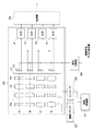
図7は、カメラ100のブロック図である。
FIG. 7 is a block diagram of the
カメラ100は、撮影動作を制御するシステム制御部21、撮像部22、転送部23、画像修復部42、現像部24、画像処理部25、多眼画像処理部26、モニタ画像処理部27、距離演算部28、AF/AE評価部29を有する。カメラ100はまた、操作部30、駆動制御部31、駆動ドライバ32、エンコーダ33、露出制御部34、記録エンコード部35、記録部36、通信エンコード部37、通信部38、外部出力部39、手ぶれ検知部40、顔検出部44を有する。
The
システム制御部21は、CPUと、CPUが実行する制御プログラムを格納するROM(いずれも図示せず)を含み、カメラ100全体の処理を制御する。操作部30は、ユーザが撮影に関する指示を与えるために用いられるキーやボタンなどの入力デバイス(シャッタボタン4、ズームレバー5等を含む)を有する。システム制御部21は、これらの入力デバイスの操作に応じたモード遷移やメニュー画面や各種情報などを表示するためのデータをモニタ43へ供給し、そのデータを撮影時/再生時の画像とともにモニタ43に表示させる。
The
図8は、撮像部22及びその関連要素のブロック図である。図7及び図8を参照して撮像部22及び関連要素の動作を詳細に説明する。
FIG. 8 is a block diagram of the
撮像部22は、上述した光学系A〜D、光学系A〜Dに対応する撮像素子15及びA/D変換部41、さらには光量調整素子17を含んでいる。画像の撮影時には、ユーザが操作部30から撮影指示を行う。撮影指示がされるとシステム制御部21は撮影指示信号を撮像部22へ送る。
The
システム制御部21からの撮影指示信号は、それぞれの撮像素子15に送られ、所定の期間、露光がなされ、光電変換により電荷が生成さる。撮像素子15はCMOS型イメージセンサであり、ローリングシャッタ方式により撮像信号がアナログで所定の読み出しタイミングで読み出され、A/D変換部41にてデジタルデータ列に変換されて転送部23へ供給される。
An imaging instruction signal from the
転送部23は、光学系A〜Dからの撮像信号につき、後工程の現像と画像処理と、処理部の構成とに応じて、データ出力の順番とタイミングを適宜調整する。図7に示す画像修復部42は、転送部23から転送された画像データに画素毎のノイズや欠陥を補修する画像処理を行い、いわゆるRAWデータとして現像部24へ供給する。現像部24は、RAWデータの各画素について色補間処理により画像信号を生成し、所定のダイナミックレンジの範囲のデジタル撮像信号として画像処理部25へ供給する。色補間処理では、撮像素子15a〜15dのカラーフィルタ構造に対応して全画素にRGB情報が割り当てられるように色でコード処理が施される。
The
操作部30のシャッタボタン4が押されると、システム制御部21から画像処理部25に画像処理の指示が出される。画像処理部25は、さらにホワイトバランス補正、ガンマ補正、シャープネス補正、彩度補正などの画像処理を行う。
When the shutter button 4 of the
次に、図7及び図9を参照して距離マップの作成に関して説明する。図9(a)は、測距原理図である。距離演算部28は、画像処理部25からの同一の焦点距離の異なる光学系の画像信号から距離マップを算出する。距離マップは、各光学系A〜Dにつき作成される。
Next, creation of a distance map will be described with reference to FIGS. FIG. 9A is a diagram showing the principle of distance measurement. The
図9(a)では、例示として、同じ焦点距離の2つの光学系A1、A2から距離マップを作成する様子を表している。光学系A1、A2の光軸をOa1、Oa2とする。光学系A1、A2に対応する撮像素子15aをそれぞれ撮像素子S1、S2と記す。被写体Pは2つの光学系A1、A2により、それぞれの撮像素子S1、S2における結像位置p1’、p2’に結像し、撮像信号として読み出される。
FIG. 9A illustrates a state in which a distance map is created from two optical systems A1 and A2 having the same focal length as an example. The optical axes of the optical systems A1 and A2 are Oa1 and Oa2.
光軸方向において、光学系A1、A2の主点P0の位置から被写体Pまでの距離を被写体距離L、主点P0から撮像素子S1、S2までの距離をfa’とする。2つの光軸Oa1、Oa2の間隔をD、光軸Oa1、Oa2から結像位置p1’、p2’までの距離をそれぞれd1、d2とする。これらには下記数式8の関係が成り立つ。
[数8]
L=D×fa'/(d1+d2)
図9(b)は、撮像素子S1、S2の撮像画像を、光軸方向に見て光軸Oa1、Oa2が一致するように示した図である。上記数式8の(d1+d2)は、図9(b)に示すように、被写体の結像位置p1’、p2’の撮像画像上での間隔Δと等しい。
In the optical axis direction, the distance from the position of the principal point P0 of the optical systems A1 and A2 to the subject P is the subject distance L, and the distance from the principal point P0 to the image sensors S1 and S2 is fa ′. The distance between the two optical axes Oa1 and Oa2 is D, and the distances from the optical axes Oa1 and Oa2 to the imaging positions p1 ′ and p2 ′ are d1 and d2, respectively. The relationship of the following formula 8 holds for these.
[Equation 8]
L = D × fa ′ / (d1 + d2)
FIG. 9B is a diagram illustrating the captured images of the image sensors S1 and S2 so that the optical axes Oa1 and Oa2 coincide when viewed in the optical axis direction. (D1 + d2) in Expression 8 is equal to the interval Δ on the captured image at the imaging positions p1 ′ and p2 ′ of the subject, as shown in FIG. 9B.
異なる光軸の画像から被写体の対応点を検出する、ブロックマッチングの手法などの相関検出式特徴点マッチング手法を用いて、撮像素子上の間隔Δを計算する。これにより、(d1+d2)が判明するから、その後、予めメモリ等に記録してある撮影状態の情報(距離fa’、光軸間隔D)を用いて、上記数式8により、距離演算部28は、被写体Pまでの被写体距離Lを取得することができる(取得手段)。
The interval Δ on the image sensor is calculated using a correlation detection type feature point matching method such as a block matching method for detecting corresponding points of an object from images of different optical axes. As a result, (d1 + d2) is determined. Thereafter, the
このような計算を画面内全体において実行すると距離マップが生成できる。ここでは2つの画像を用いて距離マップを生成する方法を説明したが、物体の影などにより対応点がない画像を補うために2つよりも多くの画像を用いるのが望ましい。 A distance map can be generated by executing such calculation over the entire screen. Although the method for generating a distance map using two images has been described here, it is desirable to use more than two images in order to compensate for an image having no corresponding point due to the shadow of an object.
算出された距離マップは、システム制御部21を介して、画像処理部25や多眼画像処理部26にフィードバックされ、再構成画像信号に被写体距離に応じたボケを重畳処理するなどの特殊効果を付与する画像処理にも用いられる。図9においては2つの光学系を用いて説明したが、複数の光学系を用いることでオクルージョンの問題や光学系の誤差などに対するロバスト性が向上する。
The calculated distance map is fed back to the
図7に示す多眼画像処理部26は、ユーザが操作部30のズームレバー5で指示した撮影画角の仮想光軸Oa0から撮影した画像に相当するRGB画像を生成する。以下、これを再構成画像信号と呼ぶ。ここで仮想光軸Oa0とは、図2に示した視点の重心O’に仮想の光学系を設定した場合の光軸である(図11(b)も参照)。多眼画像処理部26は、焦点距離が同じである光学系に対応する4つの視点のRGB画像から、仮想光軸Oa0に視点を補正した画像信号を再構成画像信号として生成する(生成手段)。これにより、撮影中の画像から、撮影後に合焦位置を変更できる再構成画像信号が生成される。
7 generates an RGB image corresponding to an image photographed from the virtual optical axis Oa0 at the photographing field angle designated by the user with the
多眼画像処理部26はさらに、ユーザが指定した撮像画角が光学系A〜Dのいずれの焦点距離とも合致しない場合は、指定された画角より一段階だけ広角の焦点距離の光学系で撮影した再構成画像信号から、指定した画角に相当する領域を切り出す。これが電子ズーム処理である。
Further, when the imaging field angle designated by the user does not match any of the focal lengths of the optical systems A to D, the multi-view
図10は、多眼画像処理部26により実行される画像出力処理のフローチャートである。
FIG. 10 is a flowchart of image output processing executed by the multi-view
まず、多眼画像処理部26は、画像処理部25から画像信号を読み込み(ステップS101)、同一焦点距離の画像をグループ化する(ステップS102)。次に、多眼画像処理部26は、各焦点距離に応じた演算係数を読み込む(ステップS103)。ここで演算係数とは、焦点距離やイメージサイズ、光学系の間隔など、視点を補正するのに必要なデータであり、図12で後述するヘッダ部におけるレンズの指定、レンズの情報、レンズの位置関係の情報が相当する。
First, the multiview
多眼画像処理部26は、演算係数を用いて、視点を補正し、再構成画像信号を生成する(ステップS104)。多眼画像処理部26は、全ての焦点距離に関する処理を終了したか否を判別し(ステップS105)、処理未終了の焦点距離があれば処理をステップS104に戻す。全ての焦点距離に関する処理を終了した場合は、多眼画像処理部26は、システム制御部21からの画角の指示に基づき、切り出しが必要か否かを判別する(ステップS106)。ユーザが指定した撮像画角が光学系A〜Dの焦点距離と異なる場合に、切り出しが必要と判別される。
The multiview
その判別の結果、多眼画像処理部26は、切り出しが必要でないなら処理をステップS109に進める一方、切り出しが必要である場合は、指示された画角よりも1段広角の再構成画像信号を読み込む(ステップS107)。そして、多眼画像処理部26は、読み込んだ再構成画像信号から指示された画角に応じて画像信号の切り出しを行う(ステップS108)。ステップS109では、多眼画像処理部26は、指示された画角と一致した再構成画像信号を出力し、本処理が終了する。
As a result of the determination, the multi-view
再構成画像は公知の手法で生成可能である。多眼画像処理部26等による再構成画像の生成方法の一例を、図9及び図11を用いて詳細に説明する。
The reconstructed image can be generated by a known method. An example of a method for generating a reconstructed image by the multi-view
図9で前述したように、被写体Pは2つの光学系によりそれぞれの撮像素子S1、S2の結像位置p1’、p2’に結像し、撮像信号として読み出される。距離演算部28はまず、画像の輝度信号分布や色信号分布の相関性に基づき、異なる光学系A1、A2で生成された画像から結像位置p1’、p2’を抽出する。距離演算部28は、上記数式8により、主点P0から被写体Pまでの被写体距離Lを求める。
As described above with reference to FIG. 9, the subject P is imaged at the imaging positions p1 'and p2' of the imaging elements S1 and S2 by the two optical systems, and is read out as an imaging signal. First, the
図11(a)は、測距原理図である。図11(a)に示すように、多眼画像処理部26は、光学系A1、A2による撮像画像の原点(光軸Oa1、Oa2が通る撮像素子S1、S2面上の位置)を基準とした結像位置p1’の座標(x1’、y1’)、結像位置p2’の座標(x2’、y2’)を求める。そして多眼画像処理部26は、被写体距離L、距離fa’、光軸間隔Dを用いて、撮像系原点でもある重心O’(図11(a)では2つの光学系A1、A2の中点)に対する計算上の被写体P’’の座標(x’’、y’’、L)を求める。
FIG. 11A is a diagram showing the principle of distance measurement. As shown in FIG. 11A, the multi-view
ここで、光学系の焦点距離の誤差や光学系と撮像素子の位置ずれ等から、図11(a)における逆トレース直線R1’’、R2’’が、計算上三次元の空間で交差しない場合がある。しかしその場合には、2つの直線が最も接近する位置に仮想の平面を設定し、その平面とそれぞれの逆トレース直線との交点の中点を座標として求めてもよい。光学系が2つよりも多いときにはそれぞれの光学系から求められる直線を用いて同様な計算を行う。 Here, the reverse trace straight lines R1 ″ and R2 ″ in FIG. 11A do not intersect in a three-dimensional space in the calculation due to an error in the focal length of the optical system, a positional deviation between the optical system and the image sensor, and the like. There is. However, in that case, a virtual plane may be set at a position where the two straight lines are closest to each other, and the midpoint of the intersection of the plane and each reverse trace straight line may be obtained as coordinates. When there are more than two optical systems, the same calculation is performed using straight lines obtained from the respective optical systems.
図11(b)は、計算上の被写体P’’を仮想の撮像素子S0面上に射影した図である。上記求められた計算上の被写体P’’を、撮像系原点(重心O’)に仮想的に配置した焦点距離fa’の光学系A0により仮想の撮像素子S0面上に射影した場合を考える。多眼画像処理部26は、この場合における仮想の撮像素子S0面上の仮想の結像位置p0’の座標(x0’、y0’)を求める。多眼画像処理部26は、このような画像処理を画像全体に対して実行し、仮想の光学系A0による仮想光軸Oa0の再構成画像を生成する。
FIG. 11B is a diagram in which the calculated subject P ″ is projected onto the virtual imaging device S0 surface. Consider a case where the calculated subject P ″ obtained above is projected onto the virtual imaging device S0 surface by the optical system A0 of the focal length fa ′ virtually arranged at the imaging system origin (center of gravity O ′). The multi-eye
図7に示す記録エンコード部35は、多眼画像処理部26から出力された再構成画像信号を所定の信号フォーマットにエンコードする。
The
図12は、再構成画像信号の記録用フォーマットの概念図である。図13は、再構成画像信号の通信用フォーマットの概念図である。 FIG. 12 is a conceptual diagram of a recording format for the reconstructed image signal. FIG. 13 is a conceptual diagram of a communication format of the reconstructed image signal.
図12に示すように、記録用フォーマットは、撮影の情報が格納されているファイルのヘッダ部のほか、画像データ部、距離マップ部からなる。ヘッダ部のデータ構成は、一例として、上記した演算係数(レンズの指定、レンズの情報、レンズの位置関係)のほか、撮影情報、画素構造及び画像形式からなる。 As shown in FIG. 12, the recording format includes an image data portion and a distance map portion in addition to a header portion of a file storing shooting information. As an example, the data structure of the header part includes imaging information, pixel structure, and image format in addition to the above-described calculation coefficients (lens designation, lens information, lens positional relationship).
ヘッダ部におけるレンズの指定には、カメラ100に設けられた光学系の構成に関する情報(例えば、光学系の数で本実施の形態では16)等が格納されている。レンズの情報には、各光学系の画角情報などが格納されている。レンズの位置関係には、各光学系の光軸の位置関係の情報が格納されている。撮影情報には、ユーザが撮影を指示したときの画角の情報、撮影した場所の経度、緯度の情報、撮影した場所の時刻の情報、撮影したときのカメラの方向の情報が格納されている。画素構造には記録された画像データの縦横の画素数の情報が格納されている。画像形式には、画像の圧縮の有無および圧縮の種類の情報が格納されている。 In the specification of the lens in the header section, information related to the configuration of the optical system provided in the camera 100 (for example, the number of optical systems is 16 in the present embodiment) is stored. The lens information stores information on the angle of view of each optical system. Information on the positional relationship of the optical axes of each optical system is stored in the positional relationship of the lenses. The shooting information stores information on the angle of view when the user instructs shooting, information on the longitude and latitude of the shooting location, information on the time of the shooting location, and information on the direction of the camera when shooting. . The pixel structure stores information on the number of vertical and horizontal pixels of the recorded image data. The image format stores information on whether or not the image is compressed and the type of compression.
記録用フォーマットにおける画像データ部には、ユーザが指示した画角で生成された再構成画像信号Eが記録され、次に光学系Aで撮像された画像信号(A1、A2、A3、A4)が記録される。その次に光学系Bで撮像された画像信号(B1、B2、B3、B4)が記録され、次に光学系Cで撮像された画像信号(C1、C2、C3、C4)が記録され、次に光学系Dで撮像された画像信号(D1、D2、D3、D4)が記録される。なお、図12では、画像信号(A3、A4、B1〜B4、C1〜C4、D1〜D3は不図示となっている。 The reconstructed image signal E generated at the angle of view designated by the user is recorded in the image data portion in the recording format, and the image signals (A1, A2, A3, A4) captured by the optical system A are then recorded. To be recorded. Next, image signals (B1, B2, B3, B4) imaged by the optical system B are recorded, and then image signals (C1, C2, C3, C4) imaged by the optical system C are recorded. The image signals (D1, D2, D3, D4) picked up by the optical system D are recorded in In FIG. 12, the image signals (A3, A4, B1 to B4, C1 to C4, and D1 to D3 are not shown).
記録用フォーマットにおける距離マップ部には、光学系Aで撮像された画像信号からの距離マップ(A)が記録され、以降、光学系B、C、Dでそれぞれ撮像された画像信号からの距離マップ(B、C、D)が記録される。 The distance map (A) from the image signal captured by the optical system A is recorded in the distance map portion in the recording format, and thereafter the distance maps from the image signals captured by the optical systems B, C, and D, respectively. (B, C, D) is recorded.
図7に示す記録部36は、記録エンコード部35でエンコードされた再構成画像信号を不図示のメモリカードなどの記録媒体に記録する。通信エンコード部37は、多眼画像処理部26から出力された再構成画像信号を図13に示す通信用フォーマットにエンコードする。
The
図13に示すように、通信用フォーマットは、撮影の情報が格納されているファイルのヘッダ部のほか、画像データ部、距離マップ部からなる。通信時のデータ量を削減するために、画像データ部は、ユーザが指示した画角で生成された再構成画像信号E、光学系Aで撮像され視点を補正した画像信号(A)、光学系B、C、Dで撮像され視点をそれぞれ補正した画像信号(B、C、D)が記録される。これに伴い、ヘッダ部には、記録用フォーマット(図12)のヘッダ部に対してレンズの位置関係が削除され、レンズの指定、レンズの情報、撮影情報、画素構造、画像形式が格納されている。 As shown in FIG. 13, the communication format includes an image data portion and a distance map portion in addition to a header portion of a file in which shooting information is stored. In order to reduce the amount of data during communication, the image data section includes a reconstructed image signal E generated at an angle of view designated by the user, an image signal (A) imaged by the optical system A and corrected for the viewpoint, and an optical system Image signals (B, C, and D) that have been picked up by B, C, and D and whose viewpoints have been corrected are recorded. Accordingly, the positional relationship of the lens is deleted from the header portion of the recording format (FIG. 12), and the lens designation, lens information, shooting information, pixel structure, and image format are stored in the header portion. Yes.
通信部38は、通信エンコード部37でエンコードされた再構成画像信号を、WiFi等の無線を通じて外部のサーバに送信する。
The
次に、その他の動作について説明する。まず、オートフォーカスの制御に関して図7で説明する。AF/AE評価部29は画像処理部25からの画像信号の輝度成分を評価し、被写体にピントが合っているかどうかを判定する。判定した結果はシステム制御部21に送信される。その判定結果が非合焦である場合は、システム制御部21は、撮像部22のフォーカス群FGを移動させる指示とその移動量及び移動方向とを駆動制御部31に送信する。
Next, other operations will be described. First, autofocus control will be described with reference to FIG. The AF /
駆動制御部の動作を図8で説明する。駆動制御部31は、システム制御部21からの指示に従い、駆動ドライバ32を制御して不図示のモータを駆動し、フォーカス群FGを合焦の方向に移動させる。フォーカス群FGの移動量はエンコーダ33で検知され、検知した移動量が駆動制御部31にフィードバックされる。駆動制御部31は、エンコーダ33から受けた移動量がシステム制御部21から指示された移動量と一致するまで、フォーカス群FGを移動させる。
The operation of the drive control unit will be described with reference to FIG. In accordance with an instruction from the
自動露出の制御に関して図7で説明する。AF/AE評価部29は、画像処理部25からの画像信号の輝度成分を評価し、露出が適切かどうかを判定する。判定した結果はシステム制御部21に送信される。その判定結果が露出不良のときには、システム制御部21は、撮像部22の露出補正量を露出制御部34に送信する。
The automatic exposure control will be described with reference to FIG. The AF /
露出制御部34の動作を図8で説明する。露出制御部34は、システム制御部21からの指示に従い、各撮像素子15の露光期間や光量調整素子17の可視光の透過率を制御し、露光量を制御する。ここで、撮像素子15と光量調整素子17の制御パターンは、ユーザが操作部30のモードダイヤル8やAEダイヤル9を操作して、公知のAEプログラム線図(不図示)を選択する等により指示する。
The operation of the
手ぶれ補正の制御に関して図7で説明する。手ぶれ検知部40は、いわゆるジャイロセンサや加速度センサ等で構成され、撮影時の手ぶれ量と手ぶれの方向を検出し、検出結果をシステム制御部21に送信する。システム制御部21は、送信された手ぶれ量及び手ぶれ方向に応じて撮像素子15の撮像信号を読み出す領域を変更する指示を撮像素子15に対して行う。撮像信号を読み出す領域の変更量は、光学系の焦点距離によって異なり、焦点距離が長いほど変更量が大きい。
The control of camera shake correction will be described with reference to FIG. The camera
外部出力の制御に関して図7で説明する。外部への画像の出力については、ユーザが操作部30から直接指示したり、カメラシステムのモード遷移に応じて対応したりする場合がある。ユーザからの指示はシステム制御部21に送られ、システム制御部21から外部出力部39に送信される。
The control of the external output will be described with reference to FIG. The output of the image to the outside may be instructed directly by the user from the
記録されている画像を出力するときには、外部出力部39は、記録部36で記録された画像からユーザが選択したファイルを再生し、再構成画像信号を読み出す。そしてそれをPC(パーソナルコンピュータ)や外部モニタなど出力先の信号フォーマットに変換して映像出力端子から出力する。撮影した画像を直接出力するときには、外部出力部39は、多眼画像処理部26からの再構成画像信号を出力先の信号フォーマットに変換して映像出力端子から出力する。
When outputting the recorded image, the
再生画像をモニタ43に表示する制御に関して図7で説明する。モニタ43への画像の表示については、ユーザが直接指示する場合と、再生機器システムのモード遷移に応じて対応する場合とがある。モニタ43には、記録された画像のサムネイル画像が表示され、ユーザがモニタ43を直接タッチして画像を選択できる。サムネイル画像は撮影のときにユーザが指定した画角の画像である。ユーザからの指示はシステム制御部21に送られ、システム制御部21からモニタ画像処理部27に送信される。
The control for displaying the reproduced image on the
顔検出部44は、画像処理部25からの画像信号に対して公知の顔検出処理を施し、撮像素子15の撮像画像内に含まれる人物の顔領域を検出する。検出した結果はシステム制御部21に送られる。なお、公知の顔検出処理としては、例えば、画像信号で表される各画素の階調色から肌色領域を抽出し、予め用意する顔の輪郭プレートとのマッチング度で顔を検出する方法がある。また、周知のパターン認識技術を用いて、目、鼻、口等の顔の特徴点を抽出することで顔検出を行う方法等も開示されている。なお、顔検出処理の手法については、上述した手法に限るものではなく、公知の種々の手法を用いることができる。
The
本実施の形態では、被写体検出(顔検出部44による顔検出)を用いて、モニタ43に後からフォーカスできる範囲を表示する例を示す。すなわち、再構成画像における合焦可能な範囲を、取得した被写体距離と併せて、撮影中にモニタ43に表示させる。
In the present embodiment, an example in which a range that can be focused later is displayed on the
図14、図15は、モニタ43への出力映像の一例を示す図である。
14 and 15 are diagrams illustrating an example of an output video to the
図14、図15に示すように、撮影中においては、システム制御部21は、モニタ43には、光学系A〜Dのうちいずれかによって取得された撮影画像を表示させる。例えば、光学系A〜Dのうちユーザが指定した画角のものから取得された撮影画像が選択的に表示される。被写体101、102は、顔検出により検出された被写体である。被写体検出枠113において被写体101の顔が検出され、被写体検出枠114において被写体102の顔が検出されている。図14に対し、図15では、カメラ100からの被写体102の距離が遠くなっている。
As shown in FIGS. 14 and 15, during photographing, the
システム制御部21はさらに、モニタ43に、撮影中の画像に重畳させて、後から(再生時に)フォーカスできる合焦可能範囲を示すフォーカスバー群103を表示させるよう制御する。フォーカスバー群103は、上下方向を長手方向にして並列に配置された4本のフォーカスバー104、105、106、107からなる。フォーカスバー104、105、106、107の長さが、それぞれ、互いに焦点距離の異なる光学系A、B、C、Dの合焦可能範囲を示す。各フォーカスバーの長さは、対応する光学系における後から合焦可能な範囲に対応している。
The
図14、図15において、カメラ100から見て、「F」が遠い側、「N」が近い側である。従って、各フォーカスバー104〜107のF側端位置(上端位置)が、最も遠い合焦可能位置を示し、N側端位置(下端位置)が、最も近い合焦可能位置を示す。フォーカスバー104を例にとると、縦の長さが光学系Aの合焦可能範囲108を示している。同様に、フォーカスバー105、106、107の縦方向の長さは、光学系B、C、Dのフォーカス可能な範囲を示している。
14 and 15, “F” is the far side and “N” is the near side when viewed from the
システム制御部21はさらに、モニタ43に、距離情報表示111(111A、111B、111C、111D)、112(112A、112B、112C、112D)を、フォーカスバー群103と併せて表示させるよう制御する(制御手段)。距離情報表示111、112は、被写体101、102のそれぞれのカメラ100からの距離(被写体距離)を示す情報であり、フォーカスバー群103の長さ方向における被写体101、102の被写体距離に対応する位置に表示される。
The
距離情報表示111A〜111Dは、それぞれ光学系A〜Dに対応するフォーカスバー104〜107の長さ方向に沿う位置(延長上も含む)に表示され、いずれもフォーカスバー104〜107の長さ方向(上下方向)における同一位置に表示される。上下方向における距離情報表示111、112の位置は、それぞれカメラ100から被写体101までの被写体距離109、110を示す。被写体距離109、110は、上述した被写体距離Lの算出手法により、撮影中に距離演算部28により取得される。
The distance information displays 111 </ b> A to 111 </ b> D are displayed at positions (including the extension) of the focus bars 104 to 107 corresponding to the optical systems A to D, respectively, and all are in the length direction of the focus bars 104 to 107. They are displayed at the same position in the (vertical direction). The positions of the distance information displays 111 and 112 in the vertical direction indicate
ただし、各4つの距離情報表示111A〜111D、112A〜112Dのうち、現在表示されている撮影中の画像の取得元である光学系に対応する各1つの距離情報表示111、112だけは、他の3つは異なる表示態様で表示される。一例として、図14、図15に示すように、光学系Bを取得元とする撮影画像が表示されているとき、フォーカスバー105に対応する距離情報表示111B、112Bだけが濃い色で表示される。そしてこれら以外の距離情報表示111A、111C、111D、及び距離情報表示112A、112C、112Dは、薄い色で表示されている。これにより、撮影画像の取得元の光学系が告知される。
However, of the four distance information displays 111A to 111D and 112A to 112D, only one distance information display 111 and 112 corresponding to the optical system from which the currently displayed image being captured is acquired These three are displayed in different display modes. As an example, as shown in FIGS. 14 and 15, when a captured image with the optical system B as an acquisition source is displayed, only the distance information displays 111 </ b> B and 112 </ b> B corresponding to the
図14を参照すると、距離情報表示111、112が、フォーカスバー104〜107のいずれの全長の範囲内に対しても収まっている。これらから、ユーザは、光学系A〜Dのいずれの画角においても、撮影後に、被写体101と被写体102のいずれに対してもフォーカスを合わせることが可能であることがわかる。 Referring to FIG. 14, the distance information displays 111 and 112 are within the full length range of the focus bars 104 to 107. From these, it is understood that the user can focus on both the subject 101 and the subject 102 after photographing at any angle of view of the optical systems A to D.
一方、図15を参照すると、距離情報表示111、112が、フォーカスバー105〜107の全長の範囲内に対して収まっているが、フォーカスバー104に対しては、距離情報表示111だけが収まり、距離情報表示112は上方に外れている。すなわち、距離情報表示112は光学系Aの合焦可能範囲から外れている。これらからユーザは、光学系B、C、Dの画角では、撮影後に被写体101、102に対してフォーカスを合わせることが可能であるが、光学系Aの画角では、撮影後に被写体102に対してフォーカスを適切に合わせることができないことがわかる。
On the other hand, referring to FIG. 15, the distance information displays 111 and 112 are within the total length of the focus bars 105 to 107, but only the distance information display 111 is within the
このようにして、複数の光学系A〜Dごとに、検出された複数の被写体が、後からフォーカスを合わせられるかどうかをユーザは認識することができる。なお、被写体の数が3以上でも同様に考えることができ、被写体数に対応して距離情報表示も増やせばよい。 In this way, the user can recognize whether or not the plurality of detected subjects can be focused later for each of the plurality of optical systems A to D. The same can be considered when the number of subjects is three or more, and the distance information display may be increased corresponding to the number of subjects.
本実施の形態によれば、撮影中の画像から生成された再構成画像における合焦可能な範囲を、被写体距離と併せて、撮影中にモニタ表示するので、撮影後に合焦可能な範囲を、被写体距離との関係と共に撮影中に認識させることができる。これにより、撮影後に意図した被写体にフォーカスが合わずに、撮影をやり直すなどの手間を省くことができる。 According to the present embodiment, the focusable range in the reconstructed image generated from the image being shot is displayed on the monitor during shooting together with the subject distance. It can be recognized during shooting together with the relationship with the subject distance. As a result, it is possible to save troubles such as re-shooting without focusing on the intended subject after shooting.
また、フォーカスバー104〜107は、焦点距離の異なる複数の光学系(A〜D)ごとに表示されるので、各々の光学系について(各画角において)合焦可能な範囲を知ることができる。しかも、フォーカスバーの長さが合焦可能な範囲に対応するので、合焦可能範囲を視覚的に把握しやすい。 In addition, since the focus bars 104 to 107 are displayed for each of a plurality of optical systems (A to D) having different focal lengths, it is possible to know a focusable range (at each angle of view) for each optical system. . Moreover, since the length of the focus bar corresponds to a focusable range, it is easy to visually grasp the focusable range.
また、距離情報表示111、112は、被写体ごとに表示されるので、各々の被写体に対する合焦可否の判断をユーザは行うことができる。しかも距離情報表示111、112は、フォーカスバー104〜107の長さ方向に沿った範囲における、被写体距離に対応する位置に表示されるので、フォーカスバーと距離情報表示との相対的位置関係から、各々の被写体に対する合焦可否を視覚的に認識しやすい。 In addition, since the distance information displays 111 and 112 are displayed for each subject, the user can determine whether or not each subject can be focused. Moreover, since the distance information displays 111 and 112 are displayed at positions corresponding to the subject distance in the range along the length direction of the focus bars 104 to 107, from the relative positional relationship between the focus bar and the distance information display, It is easy to visually recognize whether or not each subject can be focused.
また、距離情報表示111、112の表示色の濃度によって、現在、モニタ表示されている撮影画像の取得元である光学系を告知するので、モニタ表示される画角についての合焦可能範囲の認識がしやすい。 Further, since the optical system from which the captured image currently displayed on the monitor is acquired is notified based on the display color density of the distance information displays 111 and 112, the focusable range for the angle of view displayed on the monitor is recognized. Easy to do.
(第2の実施の形態)
第1の実施の形態では、モニタ表示において、被写体距離を顔検出された被写体ごとに表示させた。これに対し、本発明の第2の実施の形態では、撮影中の撮影画像を複数に分割した領域ごとに被写体距離を取得し、分割領域ごとに被写体距離を表示させる。その他の構成は第1の実施の形態と同様である。従って、図14、図15に代えて図16、図17を用いて第2の実施の形態を説明する。
(Second Embodiment)
In the first embodiment, the subject distance is displayed for each subject whose face is detected in the monitor display. On the other hand, in the second embodiment of the present invention, the subject distance is acquired for each region obtained by dividing the captured image being captured into a plurality of regions, and the subject distance is displayed for each divided region. Other configurations are the same as those of the first embodiment. Therefore, the second embodiment will be described with reference to FIGS. 16 and 17 instead of FIGS.
図16、図17は、モニタ43への出力映像の一例を示す図である。
16 and 17 are diagrams illustrating an example of an output video to the
第1の実施の形態では、被写体検出された領域に対して被写体距離を算出していたが、第2の実施の形態では、分割した領域ごとに被写体距離を距離演算部28が算出する。領域213、214は、画面を分割した際に被写体101、102が映っている領域である。領域の分割手法は問わない。
In the first embodiment, the subject distance is calculated with respect to the region where the subject is detected. In the second embodiment, the
図16、図17に示した例では、説明の簡略化のため、被写体が映っている領域213、214に対してのみ被写体距離を算出し、それを距離情報表示111、112としてフォーカスバー群103に併せて表示する例を示す。他の分割領域内の被写体についても同様に考えることができる。モニタ43に表示されるフォーカスバー群103は第1の実施の形態のものと同じである。
In the example shown in FIGS. 16 and 17, the object distance is calculated only for the
図16では、領域213にいる被写体101と、領域214にいる被写体102は、フォーカスバー群103において、距離情報表示111、112として表示されている。距離情報表示111、112とフォーカスバー群103との相対的な位置関係から、光学系ごと、被写体ごとに合焦可能範囲を視覚的に把握できる点は第1の実施の形態(図14、図15)と同様である。
In FIG. 16, the subject 101 in the
本実施の形態によれば、撮影後に合焦可能な範囲を、被写体距離との関係と共に撮影中に認識させることに関し、第1の実施の形態と同様の効果を奏することができる。特に本実施の形態では、各画角において、画面内の各分割領域にいる被写体について、後からフォーカスを合わせられるかどうかをユーザに認識させることが可能となる。さらに、人物以外の、被写体検出できない被写体に対しても、合焦可能範囲を知らせることが可能となる。 According to the present embodiment, the same effect as in the first embodiment can be achieved with respect to recognizing a focusable range after shooting together with the relationship with the subject distance during shooting. In particular, in the present embodiment, the user can recognize whether or not the subject in each divided area in the screen can be focused later at each angle of view. Further, it is possible to notify the focusable range to a subject other than a person who cannot detect the subject.
なお、第1、第2の実施の形態において、撮影後の合焦可能な範囲については、モニタ43には、少なくとも、最も近い合焦可能位置と最も遠い合焦可能位置とがわかるような表示を採用すればよい。従って、フォーカスバー群103のような表示態様に限定されない。このようにバー形式を用いない場合、距離情報表示については、最も近い合焦可能位置と最も遠い合焦可能位置の表示に対して、距離的に相対的な関係となる位置に表示させてもよい。
In the first and second embodiments, the focusable range after shooting is displayed on the
なお、現在、モニタ表示されている撮影画像の取得元である光学系を告知する態様として、距離情報表示111、112の色の濃さで区別した。しかしこれに限るものでなく、取得元の光学系とそうでない光学系とで距離情報表示の表示態様を区別すればよい。例えば、表示色や付加するマークで区別してもよい。 In addition, as an aspect of notifying the optical system that is the acquisition source of the captured image currently displayed on the monitor, the distance information displays 111 and 112 are distinguished by the color intensity. However, the present invention is not limited to this, and the display mode of the distance information display may be distinguished between the acquisition source optical system and the other optical system. For example, you may distinguish with a display color and the mark to add.
また、必ずしも距離情報表示(例えば111A〜111D)を全ての光学系に対応して表示させる必要はなく、取得元の光学系に対応する距離情報表示(例えば111A)だけを表示させ、それ以外(例えば111B〜D)は表示させない、という手法も考えられる。あるいは、距離情報表示を廃止し、取得元の光学系に対応するフォーカスバーだけを、それ以外のフォーカスバーとは色等において異なる表示態様となるようにしてもよい。なお、フォーカスバー群103の長手方向の設定は上下方向に限定されるものではない。
Further, it is not always necessary to display the distance information display (for example, 111A to 111D) corresponding to all the optical systems, only the distance information display (for example, 111A) corresponding to the optical system of the acquisition source is displayed, and otherwise ( For example, a method of not displaying 111B to D) is also conceivable. Alternatively, the distance information display may be abolished, and only the focus bar corresponding to the acquisition source optical system may have a display mode different in color or the like from the other focus bars. The setting of the longitudinal direction of the
なお、撮影中の画像から、撮影後に合焦位置を変更できる再構成画像を生成する観点からは、平面方向に複数のレンズを配置したレンズアレイを撮像素子15の被写体側に配置する構成を採用してもよい。
From the viewpoint of generating a reconstructed image from which an in-focus position can be changed after shooting from the image being shot, a configuration in which a lens array having a plurality of lenses arranged in the plane direction is arranged on the subject side of the
以上、本発明をその好適な実施形態に基づいて詳述してきたが、本発明はこれら特定の実施形態に限られるものではなく、この発明の要旨を逸脱しない範囲の様々な形態も本発明に含まれる。 Although the present invention has been described in detail based on preferred embodiments thereof, the present invention is not limited to these specific embodiments, and various forms within the scope of the present invention are also included in the present invention. included.
A、B、C、D 光学系
21 システム制御部
26 多眼画像処理部
28 距離演算部
43 モニタ
103 フォーカスバー群
111、112 距離情報表示
A, B, C,
Claims (8)
前記撮像素子から出力される画像内の被写体の被写体距離を取得する取得手段と、
前記複数の光学系に関する情報に基づいて得られる被写体距離の範囲であって、前記撮像素子から出力される画像を用いて撮影後に生成される、前記画像とは異なる合焦位置の画像が合焦位置として取り得る範囲に対応する長さのバーを、前記取得手段により取得された被写体距離と併せて前記焦点距離の異なる光学系ごとにモニタに表示させる制御手段と、
を有することを特徴とする撮像装置。 A plurality of optical systems having different focal lengths, each including an image sensor;
Obtaining means for obtaining a subject distance of a subject in an image output from the image sensor;
A range of the subject distance obtained based on the information about the plurality of optical systems, the generated after shooting using an image output from the image sensor, image Zogago different focus positions from the image Control means for displaying a bar having a length corresponding to a range that can be taken as a focal position on a monitor for each optical system having a different focal length together with the subject distance acquired by the acquisition means;
An imaging device comprising:
前記取得手段は、前記検出手段により検出された顔の距離を前記被写体距離として取得することを特徴とする請求項1乃至3のいずれか1項に記載の撮像装置。 Having a detecting means for detecting a human face included in the image being shot;
The imaging apparatus according to claim 1, wherein the acquisition unit acquires a face distance detected by the detection unit as the subject distance.
前記制御手段は、取得された前記複数の被写体の被写体距離を前記モニタに表示させることを特徴とする請求項1乃至4のいずれか1項に記載の撮像装置。 The acquisition means can acquire subject distances of a plurality of subjects,
5. The imaging apparatus according to claim 1, wherein the control unit displays the acquired subject distances of the plurality of subjects on the monitor. 6.
前記制御手段は、前記モニタに現在表示されている撮影画像の取得元である光学系を告知することを特徴とする請求項1乃至6のいずれか1項に記載の撮像装置。 The monitor selectively displays a captured image acquired by one of the plurality of optical systems having different focal lengths,
It said control means, the image pickup apparatus according to any one of claims 1 to 6, characterized in that announcing optical system which is an acquisition source of the captured image currently displayed on the monitor.
前記複数の光学系に関する情報に基づいて得られる被写体距離の範囲であって、前記撮像素子から出力される画像を用いて撮影後に生成される、前記画像とは異なる合焦位置の画像が合焦位置として取り得る範囲に対応する長さのバーを、前記取得工程により取得された被写体距離と併せて前記焦点距離の異なる光学系ごとにモニタに表示させる制御工程と、
を有することを特徴とする撮像装置の制御方法。 An acquisition step of acquiring subject distances of subjects in an image output from the imaging elements of a plurality of optical systems having different focal lengths, each including an imaging element;
A range of the subject distance obtained based on the information about the plurality of optical systems, the generated after shooting using an image output from the image sensor, image Zogago different focus positions from the image A control step of displaying a bar having a length corresponding to a range that can be taken as a focal position on a monitor for each optical system having a different focal length together with the subject distance acquired by the acquisition step;
A method for controlling an imaging apparatus, comprising:
Priority Applications (1)
| Application Number | Priority Date | Filing Date | Title |
|---|---|---|---|
| JP2013217691A JP6257260B2 (en) | 2013-10-18 | 2013-10-18 | Imaging apparatus and control method thereof |
Applications Claiming Priority (1)
| Application Number | Priority Date | Filing Date | Title |
|---|---|---|---|
| JP2013217691A JP6257260B2 (en) | 2013-10-18 | 2013-10-18 | Imaging apparatus and control method thereof |
Publications (3)
| Publication Number | Publication Date |
|---|---|
| JP2015080169A JP2015080169A (en) | 2015-04-23 |
| JP2015080169A5 JP2015080169A5 (en) | 2016-11-24 |
| JP6257260B2 true JP6257260B2 (en) | 2018-01-10 |
Family
ID=53011245
Family Applications (1)
| Application Number | Title | Priority Date | Filing Date |
|---|---|---|---|
| JP2013217691A Active JP6257260B2 (en) | 2013-10-18 | 2013-10-18 | Imaging apparatus and control method thereof |
Country Status (1)
| Country | Link |
|---|---|
| JP (1) | JP6257260B2 (en) |
Families Citing this family (3)
| Publication number | Priority date | Publication date | Assignee | Title |
|---|---|---|---|---|
| JP6578717B2 (en) | 2014-06-23 | 2019-09-25 | 株式会社リコー | Terminal device, program, role determination method, and information processing system |
| JP6648916B2 (en) * | 2015-07-27 | 2020-02-14 | キヤノン株式会社 | Imaging device |
| JP6663193B2 (en) * | 2015-09-10 | 2020-03-11 | キヤノン株式会社 | Imaging device and control method thereof |
Family Cites Families (3)
| Publication number | Priority date | Publication date | Assignee | Title |
|---|---|---|---|---|
| JP2012027048A (en) * | 2010-07-20 | 2012-02-09 | Mitsubishi Pencil Co Ltd | Method for manufacturing electrophoretic display device |
| JP6112824B2 (en) * | 2012-02-28 | 2017-04-12 | キヤノン株式会社 | Image processing method and apparatus, and program. |
| JP2015026880A (en) * | 2013-07-24 | 2015-02-05 | 株式会社ニコン | Imaging apparatus |
-
2013
- 2013-10-18 JP JP2013217691A patent/JP6257260B2/en active Active
Also Published As
| Publication number | Publication date |
|---|---|
| JP2015080169A (en) | 2015-04-23 |
Similar Documents
| Publication | Publication Date | Title |
|---|---|---|
| US10009540B2 (en) | Image processing device, image capturing device, and image processing method for setting a combination parameter for combining a plurality of image data | |
| JP5206095B2 (en) | Composition determination apparatus, composition determination method, and program | |
| JP5786412B2 (en) | Image processing apparatus, image processing method, and image processing program | |
| TWI386056B (en) | A composition determination means, a composition determination method, and a composition determination program | |
| JP5397751B2 (en) | Camera and image correction method | |
| EP2590421B1 (en) | Single-lens stereoscopic image capture device | |
| JP2011064894A (en) | Stereoscopic image display apparatus | |
| JP5425305B2 (en) | Stereoscopic image control apparatus, operation control method thereof, and operation control program thereof | |
| JP4692849B2 (en) | Stereoscopic image recording apparatus and stereoscopic image recording method | |
| US20120230549A1 (en) | Image processing device, image processing method and recording medium | |
| US9596455B2 (en) | Image processing device and method, and imaging device | |
| JP2009296561A (en) | Imaging apparatus and imaging method | |
| JP2002232913A (en) | Double eye camera and stereoscopic vision image viewing system | |
| US20110025824A1 (en) | Multiple eye photography method and apparatus, and program | |
| US20130083169A1 (en) | Image capturing apparatus, image processing apparatus, image processing method and program | |
| JP6257260B2 (en) | Imaging apparatus and control method thereof | |
| JP2009258005A (en) | Three-dimensional measuring device and three-dimensional measuring method | |
| JP2006017632A (en) | Three-dimensional image processor, optical axis adjustment method, and optical axis adjustment support method | |
| JP4946914B2 (en) | Camera system | |
| JP2020193820A (en) | Measurement device, imaging device, control method, and program | |
| JP2011217229A (en) | Imaging apparatus and display method | |
| JP2016134886A (en) | Imaging apparatus and control method thereof | |
| JP2000102035A (en) | Stereoscopic photograph system | |
| US20230171511A1 (en) | Image processing apparatus, imaging apparatus, and image processing method | |
| JP2011135374A (en) | Three-dimensional digital camera |
Legal Events
| Date | Code | Title | Description |
|---|---|---|---|
| A521 | Request for written amendment filed |
Free format text: JAPANESE INTERMEDIATE CODE: A523 Effective date: 20161005 |
|
| A621 | Written request for application examination |
Free format text: JAPANESE INTERMEDIATE CODE: A621 Effective date: 20161005 |
|
| A977 | Report on retrieval |
Free format text: JAPANESE INTERMEDIATE CODE: A971007 Effective date: 20170626 |
|
| A131 | Notification of reasons for refusal |
Free format text: JAPANESE INTERMEDIATE CODE: A131 Effective date: 20170801 |
|
| A521 | Request for written amendment filed |
Free format text: JAPANESE INTERMEDIATE CODE: A523 Effective date: 20170929 |
|
| TRDD | Decision of grant or rejection written | ||
| A01 | Written decision to grant a patent or to grant a registration (utility model) |
Free format text: JAPANESE INTERMEDIATE CODE: A01 Effective date: 20171107 |
|
| A61 | First payment of annual fees (during grant procedure) |
Free format text: JAPANESE INTERMEDIATE CODE: A61 Effective date: 20171205 |
|
| R151 | Written notification of patent or utility model registration |
Ref document number: 6257260 Country of ref document: JP Free format text: JAPANESE INTERMEDIATE CODE: R151 |