JP6253229B2 - Method for controlling the feeder of a saddle stitch binding machine - Google Patents
Method for controlling the feeder of a saddle stitch binding machine Download PDFInfo
- Publication number
- JP6253229B2 JP6253229B2 JP2012272440A JP2012272440A JP6253229B2 JP 6253229 B2 JP6253229 B2 JP 6253229B2 JP 2012272440 A JP2012272440 A JP 2012272440A JP 2012272440 A JP2012272440 A JP 2012272440A JP 6253229 B2 JP6253229 B2 JP 6253229B2
- Authority
- JP
- Japan
- Prior art keywords
- gripper
- signature
- feeder
- motomeko
- signatures
- Prior art date
- Legal status (The legal status is an assumption and is not a legal conclusion. Google has not performed a legal analysis and makes no representation as to the accuracy of the status listed.)
- Expired - Fee Related
Links
Images


Classifications
-
- B—PERFORMING OPERATIONS; TRANSPORTING
- B65—CONVEYING; PACKING; STORING; HANDLING THIN OR FILAMENTARY MATERIAL
- B65H—HANDLING THIN OR FILAMENTARY MATERIAL, e.g. SHEETS, WEBS, CABLES
- B65H39/00—Associating, collating, or gathering articles or webs
-
- B—PERFORMING OPERATIONS; TRANSPORTING
- B42—BOOKBINDING; ALBUMS; FILES; SPECIAL PRINTED MATTER
- B42B—PERMANENTLY ATTACHING TOGETHER SHEETS, QUIRES OR SIGNATURES OR PERMANENTLY ATTACHING OBJECTS THERETO
- B42B4/00—Permanently attaching together sheets, quires or signatures by discontinuous stitching with filamentary material, e.g. wire
-
- B—PERFORMING OPERATIONS; TRANSPORTING
- B42—BOOKBINDING; ALBUMS; FILES; SPECIAL PRINTED MATTER
- B42B—PERMANENTLY ATTACHING TOGETHER SHEETS, QUIRES OR SIGNATURES OR PERMANENTLY ATTACHING OBJECTS THERETO
- B42B9/00—Devices common to machines for carrying out the processes according to more than one of the preceding main groups
- B42B9/02—Devices common to machines for carrying out the processes according to more than one of the preceding main groups for opening quires or signatures
-
- B—PERFORMING OPERATIONS; TRANSPORTING
- B42—BOOKBINDING; ALBUMS; FILES; SPECIAL PRINTED MATTER
- B42B—PERMANENTLY ATTACHING TOGETHER SHEETS, QUIRES OR SIGNATURES OR PERMANENTLY ATTACHING OBJECTS THERETO
- B42B9/00—Devices common to machines for carrying out the processes according to more than one of the preceding main groups
- B42B9/04—Devices common to machines for carrying out the processes according to more than one of the preceding main groups for conveying downwardly-open signatures
-
- B—PERFORMING OPERATIONS; TRANSPORTING
- B42—BOOKBINDING; ALBUMS; FILES; SPECIAL PRINTED MATTER
- B42C—BOOKBINDING
- B42C1/00—Collating or gathering sheets combined with processes for permanently attaching together sheets or signatures or for interposing inserts
- B42C1/12—Machines for both collating or gathering and permanently attaching together the sheets or signatures
-
- B—PERFORMING OPERATIONS; TRANSPORTING
- B65—CONVEYING; PACKING; STORING; HANDLING THIN OR FILAMENTARY MATERIAL
- B65H—HANDLING THIN OR FILAMENTARY MATERIAL, e.g. SHEETS, WEBS, CABLES
- B65H3/00—Separating articles from piles
- B65H3/08—Separating articles from piles using pneumatic force
- B65H3/0808—Suction grippers
- B65H3/085—Suction grippers separating from the bottom of pile
- B65H3/0858—Suction grippers separating from the bottom of pile this action resulting merely in a curvature of each article being separated
- B65H3/0875—Suction grippers separating from the bottom of pile this action resulting merely in a curvature of each article being separated the final separation being performed by mechanical grippers
-
- B—PERFORMING OPERATIONS; TRANSPORTING
- B65—CONVEYING; PACKING; STORING; HANDLING THIN OR FILAMENTARY MATERIAL
- B65H—HANDLING THIN OR FILAMENTARY MATERIAL, e.g. SHEETS, WEBS, CABLES
- B65H39/00—Associating, collating, or gathering articles or webs
- B65H39/02—Associating,collating or gathering articles from several sources
- B65H39/04—Associating,collating or gathering articles from several sources from piles
- B65H39/043—Associating,collating or gathering articles from several sources from piles the piles being disposed in juxtaposed carriers
-
- B—PERFORMING OPERATIONS; TRANSPORTING
- B65—CONVEYING; PACKING; STORING; HANDLING THIN OR FILAMENTARY MATERIAL
- B65H—HANDLING THIN OR FILAMENTARY MATERIAL, e.g. SHEETS, WEBS, CABLES
- B65H39/00—Associating, collating, or gathering articles or webs
- B65H39/02—Associating,collating or gathering articles from several sources
- B65H39/04—Associating,collating or gathering articles from several sources from piles
- B65H39/055—Associating,collating or gathering articles from several sources from piles by collecting in juxtaposed carriers
-
- B—PERFORMING OPERATIONS; TRANSPORTING
- B65—CONVEYING; PACKING; STORING; HANDLING THIN OR FILAMENTARY MATERIAL
- B65H—HANDLING THIN OR FILAMENTARY MATERIAL, e.g. SHEETS, WEBS, CABLES
- B65H5/00—Feeding articles separated from piles; Feeding articles to machines
- B65H5/30—Opening devices for folded sheets or signatures
- B65H5/305—Opening devices for folded sheets or signatures comprising rotary means for opening the folded sheets
- B65H5/307—Opening devices for folded sheets or signatures comprising rotary means for opening the folded sheets two opposite rotary means, both having gripping means
-
- B—PERFORMING OPERATIONS; TRANSPORTING
- B65—CONVEYING; PACKING; STORING; HANDLING THIN OR FILAMENTARY MATERIAL
- B65H—HANDLING THIN OR FILAMENTARY MATERIAL, e.g. SHEETS, WEBS, CABLES
- B65H5/00—Feeding articles separated from piles; Feeding articles to machines
- B65H5/32—Saddle-like members over which partially-unfolded sheets or signatures are fed to signature-gathering, stitching, or like machines
-
- B—PERFORMING OPERATIONS; TRANSPORTING
- B65—CONVEYING; PACKING; STORING; HANDLING THIN OR FILAMENTARY MATERIAL
- B65H—HANDLING THIN OR FILAMENTARY MATERIAL, e.g. SHEETS, WEBS, CABLES
- B65H2301/00—Handling processes for sheets or webs
- B65H2301/30—Orientation, displacement, position of the handled material
- B65H2301/32—Orientation of handled material
- B65H2301/322—Riding over one elongated or saddle-like member
-
- B—PERFORMING OPERATIONS; TRANSPORTING
- B65—CONVEYING; PACKING; STORING; HANDLING THIN OR FILAMENTARY MATERIAL
- B65H—HANDLING THIN OR FILAMENTARY MATERIAL, e.g. SHEETS, WEBS, CABLES
- B65H2511/00—Dimensions; Position; Numbers; Identification; Occurrences
- B65H2511/40—Identification
- B65H2511/415—Identification of job
-
- B—PERFORMING OPERATIONS; TRANSPORTING
- B65—CONVEYING; PACKING; STORING; HANDLING THIN OR FILAMENTARY MATERIAL
- B65H—HANDLING THIN OR FILAMENTARY MATERIAL, e.g. SHEETS, WEBS, CABLES
- B65H2513/00—Dynamic entities; Timing aspects
- B65H2513/50—Timing
-
- B—PERFORMING OPERATIONS; TRANSPORTING
- B65—CONVEYING; PACKING; STORING; HANDLING THIN OR FILAMENTARY MATERIAL
- B65H—HANDLING THIN OR FILAMENTARY MATERIAL, e.g. SHEETS, WEBS, CABLES
- B65H2701/00—Handled material; Storage means
- B65H2701/10—Handled articles or webs
- B65H2701/19—Specific article or web
- B65H2701/1932—Signatures, folded printed matter, newspapers or parts thereof and books
Landscapes
- Engineering & Computer Science (AREA)
- Mechanical Engineering (AREA)
- Textile Engineering (AREA)
- Folding Of Thin Sheet-Like Materials, Special Discharging Devices, And Others (AREA)
- Feeding Of Articles By Means Other Than Belts Or Rollers (AREA)
Description
本発明は、請求項1の上位概念に記載の中綴じ製本機のフィーダを制御する方法に関する。
The present invention relates to a method for controlling a feeder of a saddle stitch binding machine according to the superordinate concept of
ドイツ連邦共和国特許出願公開第1100043号から、折丁をくわえて固定するための製本機用グリッパが公知であり、グリッパの閉鎖動作は、空気式の作動シリンダを操作することによって実施される。作動シリンダが真空にされるか、又は、作動シリンダに圧縮空気が印加されると、ピストンロッドに固定されたグリッパフィンガが、バネの力に対抗して引き寄せられる。圧縮空気又は負圧空気は、制御バルブを介して作動シリンダに供給され、この制御バルブが、調整可能なカムディスクによって制御されて、グリップ力が調整される。カムディスクは、カムの曲線に応じて固定的な調整特性を有する。カムディスクの調整方法の詳細は、上記文献には開示されていない。 German Patent Application No. 1100043 discloses a bookbinding gripper for adding and fixing signatures, and the closing operation of the gripper is carried out by operating a pneumatic working cylinder. When the working cylinder is evacuated or compressed air is applied to the working cylinder, the gripper fingers fixed to the piston rod are attracted against the spring force. Compressed air or negative pressure air is supplied to the working cylinder via a control valve, which is controlled by an adjustable cam disk to adjust the grip force. The cam disk has a fixed adjustment characteristic according to the curve of the cam. The details of the cam disk adjusting method are not disclosed in the above-mentioned document.
印刷機の場合には、ドイツ連邦共和国特許第4221929号から、ドラムに接続されたグリッパの動作をコンピュータによって制御することによって、変化する動作条件に対する迅速な適合が可能となり、被印刷材料に依存してグリップ力を調整できるということも公知である。グリッパの動作は、空気式のピストン・シリンダ・ユニットによって制御され、ここではストローク測定システムを用いて、ドラムの回転角に依存して、目標値・実際値の比較によるピストンの調整位置が調整される。この文献では、ピストンの調整位置を計算する際に、被印刷材料のどの特性パラメータが使用されるかは詳細に記載されていない。 In the case of printing presses, from German Patent No. 4221929, the operation of the gripper connected to the drum is controlled by a computer, allowing a quick adaptation to changing operating conditions, depending on the material to be printed. It is also known that the grip force can be adjusted. The operation of the gripper is controlled by a pneumatic piston / cylinder unit, where the stroke adjustment system is used to adjust the piston adjustment position by comparing the target and actual values depending on the rotation angle of the drum. The In this document, it is not described in detail which characteristic parameter of the printing material is used when calculating the adjustment position of the piston.
ドイツ連邦共和国特許出願公開第19752017号に記載されている中綴じ製本機は、複数の折丁フィーダを含む。フィーダのドラムの回転速度は、紙質に依存して遅延又は加速され、この際、ギャザリングチェーンの速度は等速である。 The saddle stitch binding machine described in German Patent Application Publication No. 19752017 includes a plurality of signature feeders. The rotation speed of the feeder drum is delayed or accelerated depending on the paper quality, and the speed of the gathering chain is constant.
ドイツ連邦共和国特許出願公開第19841265号からは、中綴じ製本機のフィーダに、折丁の長さ及び幅を検出する複数のセンサが設けられていることが公知である。センサ信号に基づいて、見当合わせストッパを自動的に調整設定することができる。搬送中に折丁を保持するグリッパは、従来通りにカム機構によって操作される。 From DE 198 41 265 A1, it is known that a feeder of a saddle stitch binding machine is provided with a plurality of sensors for detecting the length and width of a signature. The registration stopper can be automatically adjusted based on the sensor signal. The gripper that holds the signature during conveyance is operated by a cam mechanism as usual.
本発明の課題は、中綴じ製本機のフィーダを制御するための方法において、フィーダを調整設定する際の操作コストを低減し、折丁を輸送装置の上に載置する際の精度を高め、丁合い及び綴じの質を改善することである。 The object of the present invention is to reduce the operation cost when adjusting and setting the feeder in the method for controlling the feeder of the saddle stitch binding machine, and to improve the accuracy when placing the signature on the transport device, To improve the quality of collation and binding.
この課題は、中綴じ製本機のフィーダを制御する方法であって、マガジンの折丁スタックから、少なくとも1つのグリッパによって折丁を順次分離して、輸送装置の上に載置する際に、グリッパの開放及び閉鎖と、ステッチャの操作とを、制御装置の調整信号による遠隔操作によって実施する、方法において、前記調整信号を、前記折丁の寸法及び頁数に関するデータから形成する、ことを特徴とする請求項1に記載の方法によって解決される。有利な実施形態は、従属請求項に記載されている。
This problem is a method for controlling a feeder of a saddle stitch binding machine, wherein a gripper is sequentially separated from a signature stack of a magazine by at least one gripper and placed on a transport device. The opening and closing of the sewing machine and the operation of the stitcher are carried out by remote control by means of an adjustment signal of the control device, wherein the adjustment signal is formed from data relating to the size and number of pages of the signature. This is solved by the method according to
本発明によれば、中綴じ製本機のフィーダを制御する際に、グリッパの開放時点乃至閉鎖時点がプログラミング制御され、無段階に、フォーマットに依存して調整される。このために、折丁の寸法及び頁数に関するデータが制御装置に入力され、これらのデータから、グリッパの調整機構のための調整信号が形成される。折丁の自動化された分離により、切換時間及び反応時間を、製品に関連して変化させることができる。空気式の制御部を使用する場合には、機械的な構成要素の数を低減することができ、製本コストは僅かになる。機械的な摩耗箇所の数が低減されることによって、フィーダの安全性が改善される。グリップ力が可変に調整されることによって、折丁に跡が形成されるのを回避することができる。 According to the present invention, when the feeder of the saddle stitch binding machine is controlled, the opening time or closing time of the gripper is controlled by programming and adjusted steplessly depending on the format. For this purpose, data relating to the size of the signature and the number of pages are input to the control device, and from these data an adjustment signal for the adjustment mechanism of the gripper is formed. Due to the automated separation of signatures, the switching time and reaction time can be varied in relation to the product. When the pneumatic control unit is used, the number of mechanical components can be reduced, and the bookbinding cost is small. By reducing the number of mechanical wear points, the safety of the feeder is improved. By adjusting the grip force variably, it is possible to avoid the formation of a mark on the signature.
以下では、本発明を、実施例に基づいてより詳細に説明する。 In the following, the present invention will be described in more detail based on examples.
図1に図示した中綴じ製本機は、製本方向1に連続して配置された例えば3つのフィーダ2〜4と、ステッチャ5と、クロスコンベヤ(横送り機構)6とを含む。フィーダ2〜4において分離された折丁7〜9は、エンドレスに循環するギャザリングチェーン10の上に下開きになって上下に重なり合うよう順次載置されていき、ステッチャ5へと搬送される。丁合いされた折丁7〜9は、ステッチャ5において、背側から針金で綴じることによって互いに結合される。互いに結合された折丁7〜9は、横送り機構6の後、トリマ(化粧断ち用裁断機)へと転送されるべく新しい製本方向11へと移動する。
The saddle stitch bookbinding machine illustrated in FIG. 1 includes, for example, three
図2に示すフィーダ3の断面図から分かるように、折丁7は、マガジン12の中に上下に積み重ねられている。マガジン12の底部は、水平線に対して傾斜している。折り畳まれた折丁7のフロントエッジは、見当合わせレール13に当接し、折り畳まれた折丁7のサイドエッジは、サイドストッパ14に当接している。サイドストッパ14は、折丁7の背の長さLに合うよう、モータ15及びスピンドル駆動部16によって、紙平面に対して垂直の方向17に調節可能である。モータ15は、制御装置18に接続されている。
As can be seen from the cross-sectional view of the
積み重ねられた折丁スタックの下面から折丁7を1つ1つ分離するため、マガジン12の底部に設けられた開口部19の下側に、吸引グリッパ20が配置されている。吸引グリッパ20は、中空軸21に固定されており、規則的な分離リズムで中空軸21の軸を中心に旋回可能となっている。
In order to separate the
図2には、分離された1つの折丁7.1が、吸引グリッパ20から、分離ドラム23の機械的グリッパ22へと移された状況が図示されている。分離ドラム23は、自身の軸24を中心にして方向25へと回転する。分離された折丁7.1に先行する折丁7.2は、分離ドラム23の別の機械的グリッパ26に保持されている。グリッパ26は、軸24を基準にしてグリッパ22とは対称に位置する。
FIG. 2 shows the situation where one separated signature 7.1 has been transferred from the
分離ドラム23が方向25へとさらに回転すると、折丁7.2のフロントエッジが、袋状のストッパ27に到着する。ストッパ27は、折丁の幅B1,B2に応じて、モータ28及び伝動装置29によって、軸24を中心に方向30へと旋回可能である。モータ28は、制御装置18に接続されている。
When the separating
分離ドラム23の下側には別の2つのドラム31,32が配置されており、これらのドラムは、矢印33,34の方向へと互いに反対方向に回転する。図2は、折丁7.2に先行する折丁7.3が、ドラム31,32によって開かれる状況を図示している。折丁7.3のフロントエッジがストッパ27に当接している間に、分離ドラム23にて後続する折丁7.3の端部が、ドラム31のダブルグリッパ35,36によってくわえられている。折丁7.3のラップ部分(Vorfalz)は、カバーグリッパ36から、オープニングドラム32のグリッパ37へと渡される。折丁7.3は、両端が引っ張られて広げられ、ギャザリングチェーン10の上に落下される。折丁7.3は、フィーダ2によって既にギャザリングチェーン10の上に載置されている折丁7.4の上に載置される。
Two
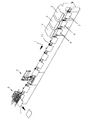
図3及び図4は、分離ドラム23のグリッパ22,26の動作の空気式制御部を図示している。分離ドラム23は、2つのドラムプレート23.1,23.2から構成されており、これらのドラムプレートは、中空軸24に回転不能に固定されている。プレート23.1と23.2の間には、空気式作動シリンダ38,39が配置されており、これらの空気式作動シリンダ38,39から、それぞれ2つの空気式制御管40.1〜40.4が、軸24の内部にあるチャネル41.1〜41.4へと導かれている。作動シリンダ38,39のための圧縮空気は、それぞれ、チャネル41.1〜41.4の端部に設けられた回転式フィードスルー42.1〜42.4を介して供給される。作動シリンダ38,39の作動ピストンロッド43,44は、クランク45.1,45.2,46.1,46.2と結合されており、これらのクランク45.1,45.2,46.1,46.2は、グリッパ22のグリッパ軸47.1,47.2,48.1,48.2に回転不能に固定されている。各プレート23.1,23.2には、それぞれグリッパペア22.1,26.1;22.2,26.2が設けられている。作動シリンダ38,39から作動ピストンロッド43,43が進入及び脱出する際に、グリッパ軸47,48に、グリッパ22,26の閉鎖乃至開放を引き起こすトルクが印加される。
3 and 4 illustrate a pneumatic control unit for the operation of the
グリッパ22,26の開放及び閉鎖は、折丁7の寸法及び頁数nに依存して実施される。折丁幅B1<B2を有する正ラップの折丁NF(Nachfalzbogen)であるか(図5.1)、又は、同じ折丁幅B1=B2を有する折丁であるか(図5.2)、又は、折丁幅B1>B2を有する逆ラップの折丁VF(Vorfalzbogen)であるか(図5.3)に応じて、図5に図示した寸法が考慮される。寸法に関する別のデータは、折丁の厚さd及び用紙重量Gである。
The opening and closing of the
以下、図6に基づいて、本発明の方法の実施について説明する:制御装置18は、とりわけ操作者入力のための入力装置49を含み、入力装置49はコンピュータ50に接続されている。コンピュータ50は、以下のパラメータに対する操作者入力のためのメモリを含む:折丁幅B1、折丁幅B2、背の長さL、用紙重量g、頁数n、折り方(例えば、正ラップの折丁NF、逆ラップの折丁VF、又は、ラップ無し折丁Fsaug(Saugerbogen)等)、及び、圧力目標値psollである。
In the following, the implementation of the method according to the invention will be described on the basis of FIG. 6: the
コンピュータ50では、入力されたパラメータが処理され、フィーダ2〜4内の種々の要素が事前設定される。背の長さLからは、モータ15による、マガジン12におけるサイドストッパ14の事前設定が行われる。折丁幅B1は、モータ28による見当合わせストッパ27の事前調整と、分離ドラムにおけるグリッパ22,26のグリッパ開角αoeの事前調整に関連している。2つの折丁幅B1,B2は、ドラム31,32におけるグリッパ35〜37のグリッパ閉角αsを事前調整するために使用される。背の長さL、折丁幅B1,B2、及び、折丁厚さdは、厚み検査装置の事前調整、針金供給装置の事前調整、ステッチャ5のクリンチャ工具の事前調整、ステップコンベヤ(Schrittband)の高さの事前調整を生じさせる。折丁厚さdに基づき、分離ドラム23のグリッパ22,26のグリップ力Fが事前調整される。予め決められる目標圧力psollは、グリップ力Fを事前調整する際、及び、回転式フィードスルー42.1〜42.4に接続されている2方向バルブ51.1〜51.4の切換時間tschaltを事前調整する際に、影響力を有する。バルブ51.1〜51.4の切換時間tschaltは制御可能であり、このために、バルブ51.1〜51.4とコンピュータ50との間に接続52が存在する。
In the
圧力目標値psollは、接続53を介してコンピュータ50から圧力調整器54へと伝送される。圧力実際値pistは、圧力調整器54から接続55を介してコンピュータ50へと伝送され、コンピュータ50において、圧力目標値psollとの比較が常に実施される。圧力目標値psollと圧力実際値pistが一致する場合には、切換時間tschaltは一定のままである。圧力実際値pistが圧力目標値psollよりも大きい場合には、この圧力実際値pistのために必要な切換時間tschaltが、バルブ51.1〜51.4に転送される。さらに、圧力を圧力目標値psollまで下げるとの情報が、圧力調整器54へと伝送される。圧力実際値pistが圧力目標値psollよりも小さい場合にも、この圧力実際値pistのために必要な切換時間tschaltがバルブ51.1〜51.4に伝送され、圧力を圧力目標値psollにまで上げるとの情報が、圧力調整器54へと転送される。圧力調整器54と、圧力実際値pistのフィードバックとを用いて、折丁の分離に必要グリッパ開角とグリッパ閉角とが常に一定に保たれるよう保証することができる。
The pressure target value p soll is transmitted from the
プログラムによって算出される圧力目標値psollに加えて、操作者は、動作中にいつでも製本の進行を邪魔することなく、各フィーダ2〜4に対して個別的に、所期の超過圧力psollを手動で設定することができる。手動介入の後、圧力目標値psollと圧力実際値pistとの間で再び通常の目標値・実際値の比較が行われる。
In addition to the pressure target value p soll calculated by the program, the operator can individually perform the desired overpressure p soll individually for each of the
全ての調整設定乃至変更は、コンピュータ50に記憶される。後続の入力が同一の場合には、記憶されたデータを呼び出すことができる。これにより調整時間が短縮され、動作コストが低減される。
All adjustment settings or changes are stored in the
グリッパ22,26を操作するための圧縮空気は、ポンプ56によって供給され、このポンプ56は、管理ユニット57を介して圧力調整器54に接続されている。圧力調整器54から接続58を介して圧縮空気がバルブ51.1〜51.4へと供給される。これらのバルブ51.1〜51.4は、2方向の切換に応じて、圧縮空気を、回転式フィードスルー42.1〜42.4を介して作動シリンダ38,39へと転送する。ドラム23,31,32は、制御装置18によって同期駆動され、この際に、ドラム23の実際の回転数乃至実際の回転角αを制御装置18乃至コンピュータ50に出力するために、軸24に付いているロータリーエンコーダ59が使用される。本発明は、記載した実施形態に制限されていない。ドラム31、32のグリッパ35〜37のためにも、グリッパ動作の自動化された制御を行うことが可能である。空気式の調整要素の代わりに、電気式乃至電磁式の調整要素を使用することも可能である。
Compressed air for operating the
1 製本方向
2〜4 フィーダ
5 ステッチャ
6 クロスコンベヤ
7〜9 折丁
10 ギャザリングチェーン
11 製本方向
12 マガジン
13 見当合わせレール
14 サイドストッパ
15 モータ
16 スピンドル駆動部
17 方向
18 制御装置
19 開口部
20 吸引グリッパ
21 中空軸
22 グリッパ
23 分離ドラム
24 軸
25 方向
26 グリッパ
27 ストッパ
28 モータ
29 伝動装置
30 方向
31,32 ドラム
33,34 矢印
35,36 ダブルグリッパ
37 グリッパ
38,39 作動シリンダ
40 制御管
41 チャネル
42 回転式フィードスルー
43,44 ピストンロッド
45,46 クランク
47,48 グリッパ軸
49 入力装置
50 コンピュータ
51 バルブ
52,53 接続
54 圧力調整器
55 接続
56 ポンプ
57 管理ユニット
58 接続
59 ロータリーエンコーダ
DESCRIPTION OF
Claims (5)
マガジン(12)の折丁スタックから、少なくとも1つのグリッパ(22,26,35〜37)によって折丁(7〜9)を順次分離して、輸送装置(10)の上に載置する際に、分離ドラム(23)のグリッパ(22,26)の開放及び閉鎖を、制御装置(18,50)の調整信号による遠隔操作によって実施する、
方法において、
前記調整信号を、前記折丁(7〜9)の寸法及び頁数に関するデータから形成し、
前記グリッパ(22,26)の操作前に、折丁幅(B)と、正ラップ又は逆ラップを使用する場合の折丁幅(B1,B2)と、頁数(n)と、を前記制御装置(18,50)に入力する、
ことを特徴とする方法。 A method for controlling a feeder of a saddle stitch binding machine,
When the signatures (7-9) are sequentially separated from the signature stack of the magazine (12) by at least one gripper (22, 26, 35-37) and placed on the transport device (10). the opening and closing chain grippers (22, 26) of the separating drum (23), carried out by remote control by the adjustment signal of the control device (18, 50),
In the method
The adjustment signal is formed from data relating to the dimensions and the number of pages of the signatures (7-9) ,
Before the gripper (22, 26) is operated, the signature width (B), the signature width (B1, B2) when using the normal wrap or reverse wrap, and the number of pages (n) are controlled. Input to the device (18, 50),
A method characterized by that.
請求項1記載の方法。 Before the operation of the gripper (22, 26) of the separating drum (23), the back of the length (L), at least one, data relating to the signature (7-9) of the paper weight (g) Is input to the control device (18, 50),
請 Motomeko 1 method described.
請求項1記載の方法。 Gripper open position (alpha oe), the gripper closed position (alpha s), gripper closing force (F), the position of the magazine side stoppers (14), the thickness measuring device which summarized signatures to one (7-9) target value adjustment by, wire supply of the scan Tetcha (5), the operation of the clincher of the for bending the wire stitcher (5), to control or adjust at least one parameter of,
請 Motomeko 1 method described.
請求項1記載の方法。 When the grippers (22, 26) fixed to the rotating element (23) are used, the adjustment signal is additionally formed from the output signal of the rotary encoder (59) indicating the rotational position of the rotating element (23). ,
請 Motomeko 1 method described.
請求項1記載の方法。 At least one controllable pneumatic working cylinder (38, 39) is used for the operation of the gripper (22, 26);
請 Motomeko 1 method described.
Applications Claiming Priority (2)
| Application Number | Priority Date | Filing Date | Title |
|---|---|---|---|
| DE102011120994A DE102011120994A1 (en) | 2011-12-14 | 2011-12-14 | Method of controlling an investor of a saddle stitcher |
| DE102011120994.1 | 2011-12-14 |
Publications (3)
| Publication Number | Publication Date |
|---|---|
| JP2013123918A JP2013123918A (en) | 2013-06-24 |
| JP2013123918A5 JP2013123918A5 (en) | 2015-12-03 |
| JP6253229B2 true JP6253229B2 (en) | 2017-12-27 |
Family
ID=47278145
Family Applications (1)
| Application Number | Title | Priority Date | Filing Date |
|---|---|---|---|
| JP2012272440A Expired - Fee Related JP6253229B2 (en) | 2011-12-14 | 2012-12-13 | Method for controlling the feeder of a saddle stitch binding machine |
Country Status (5)
| Country | Link |
|---|---|
| US (1) | US9415969B2 (en) |
| EP (1) | EP2604438B1 (en) |
| JP (1) | JP6253229B2 (en) |
| CN (1) | CN103158388B (en) |
| DE (1) | DE102011120994A1 (en) |
Families Citing this family (3)
| Publication number | Priority date | Publication date | Assignee | Title |
|---|---|---|---|---|
| EP2492107B1 (en) * | 2011-02-25 | 2013-07-24 | Müller Martini Holding AG | Thread sewing machine |
| CN103738775A (en) * | 2013-12-17 | 2014-04-23 | 安徽华印机电股份有限公司 | Section dropping speed reduction mechanism |
| DE102015226322B4 (en) * | 2015-12-21 | 2020-11-19 | Koenig & Bauer Ag | Delivery for a sheet processing machine and method for depositing sheets |
Family Cites Families (31)
| Publication number | Priority date | Publication date | Assignee | Title |
|---|---|---|---|---|
| DE1100043B (en) | 1958-08-15 | 1961-02-23 | Leipziger Buchbindereimaschine | Gripper on printing and bookbinding machines for gripping and holding sheets made of paper, cardboard or similar material |
| US4078784A (en) * | 1976-10-07 | 1978-03-14 | Harris Corporation | Signature opening apparatus |
| US4162066A (en) * | 1977-06-06 | 1979-07-24 | Mccain Manufacturing Corporation | Signature machines |
| JPH075210B2 (en) * | 1987-12-08 | 1995-01-25 | 株式会社西日本新聞社 | Inspection device for newspaper printing |
| US4844433A (en) * | 1988-04-11 | 1989-07-04 | R. R. Donnelley & Sons Company | Packer box undersized signature handling kit |
| US5029832A (en) * | 1989-04-14 | 1991-07-09 | Bell & Howell Phillipsburg Co. | In-line rotary inserter |
| US5042232A (en) * | 1989-04-14 | 1991-08-27 | Bell & Howell Phillipsburg Co. | In-line rotary inserter |
| JP2925345B2 (en) * | 1991-02-23 | 1999-07-28 | 大日本印刷株式会社 | Paper feeder and collating device |
| DE4200406C2 (en) * | 1992-01-10 | 1996-10-10 | Heidelberger Druckmasch Ag | Gripper device on sheet-fed rotary printing machines |
| DE4221929C2 (en) | 1992-07-03 | 1997-11-20 | Heidelberger Druckmasch Ag | Gripper control for sheet grippers on a sheet-guiding cylinder or the like in a printing press |
| DE4343146C2 (en) * | 1993-03-12 | 2000-02-17 | Heidelberger Druckmasch Ag | Device for separating paper products, for example signatures and newspapers from a stack by means of a rotatably mounted gripper drum |
| US5518231A (en) * | 1993-04-19 | 1996-05-21 | Xerox Corporation | Self adjusting sheet gripping apparatus |
| JPH0924605A (en) * | 1995-06-22 | 1997-01-28 | Grapha Holding Ag | Method and apparatus for optimizing treatment efficiency of apparatus for treating sheet or printing sheet and insert into bound product |
| JPH0948184A (en) * | 1995-08-09 | 1997-02-18 | Tosho Printing Co Ltd | Method and apparatus for bookbinding saddle stitched book |
| US5893824A (en) * | 1996-08-13 | 1999-04-13 | Heidelberg Finishing Systems, Inc. | Transfer drum assembly for signature handling |
| JP3786481B2 (en) * | 1996-10-15 | 2006-06-14 | 大日本印刷株式会社 | Initial setting method of operation timing in paper feeder |
| DE19752017A1 (en) | 1997-11-24 | 1999-05-27 | Karl Prof Dr Ing Straus | Removing moisture from sludge, paste and suspension |
| DE19752015A1 (en) * | 1997-11-24 | 1999-05-27 | Brehmer Buchbindereimaschinen | Saddle stitcher for folded sheets and method for drive control of a saddle stitcher |
| DE19841265A1 (en) | 1998-09-09 | 2000-03-16 | Brehmer Buchbindereimaschinen | Folded sheet feeder for saddle stitchers |
| US6606944B1 (en) * | 2000-11-17 | 2003-08-19 | Heidelberger Druckmaschinen Ag | Device and method for determining a signature lap |
| DE10349483A1 (en) * | 2003-10-21 | 2005-06-02 | Heidelberger Druckmaschinen Ag | Glueing personalized advertising cards during collection stapling |
| US7748517B2 (en) * | 2004-02-04 | 2010-07-06 | Goss International Americas, Inc. | Signature transport device |
| DE102004021958A1 (en) * | 2004-05-04 | 2005-12-01 | Heidelberger Druckmaschinen Ag | Saddle stitcher for brochures |
| EP1690696B1 (en) * | 2005-02-15 | 2008-11-05 | Heidelberger Druckmaschinen AG | Method and apparatus for the pressing of print signatures |
| US7510184B2 (en) * | 2005-05-25 | 2009-03-31 | Goss International Americas, Inc. | Paper thickness measuring device for a rotary paper feeding device |
| DE102006015464A1 (en) * | 2006-03-31 | 2007-10-04 | Heidelberger Druckmaschinen Ag | Saddle stitcher with a folded sheet feeder |
| EP1952986B1 (en) * | 2007-01-30 | 2014-11-19 | Müller Martini Holding AG | Device for processing printed products with an illumination device for setting up, adjusting and/or controlling said device |
| WO2008123151A1 (en) * | 2007-03-30 | 2008-10-16 | Toppan Printing Co., Ltd. | Section feeding apparatus, and saddle stitcher having the section feeding apparatus |
| DE102007023768A1 (en) * | 2007-05-22 | 2008-11-27 | Heidelberger Druckmaschinen Ag | Apparatus for feeding sheets to a processing machine and method for feeding the apparatus |
| DE102009012724A1 (en) * | 2009-03-11 | 2010-09-16 | Heidelberger Druckmaschinen Ag | Saddle stitcher and method for operating a saddle stitcher |
| US8702089B2 (en) * | 2011-07-22 | 2014-04-22 | Bell and Howell, LLC. | Method and system to feed inserts with a rotary and gripper system |
-
2011
- 2011-12-14 DE DE102011120994A patent/DE102011120994A1/en not_active Withdrawn
-
2012
- 2012-11-20 EP EP12193360.0A patent/EP2604438B1/en not_active Not-in-force
- 2012-12-13 JP JP2012272440A patent/JP6253229B2/en not_active Expired - Fee Related
- 2012-12-14 US US13/714,709 patent/US9415969B2/en not_active Expired - Fee Related
- 2012-12-14 CN CN201210544268.2A patent/CN103158388B/en not_active Expired - Fee Related
Also Published As
| Publication number | Publication date |
|---|---|
| EP2604438A3 (en) | 2014-01-22 |
| US9415969B2 (en) | 2016-08-16 |
| US20130154177A1 (en) | 2013-06-20 |
| CN103158388B (en) | 2017-06-16 |
| CN103158388A (en) | 2013-06-19 |
| JP2013123918A (en) | 2013-06-24 |
| EP2604438A2 (en) | 2013-06-19 |
| DE102011120994A1 (en) | 2013-06-20 |
| EP2604438B1 (en) | 2015-06-03 |
Similar Documents
| Publication | Publication Date | Title |
|---|---|---|
| JP5441585B2 (en) | Method and apparatus for laterally adjusting a sheet in a processing machine | |
| JP5441451B2 (en) | Device for adjusting the position of a sheet with a stopper | |
| JP6253229B2 (en) | Method for controlling the feeder of a saddle stitch binding machine | |
| US6623000B2 (en) | Apparatus and method for separating sheet material by means of a reciprocating disk separator | |
| US7815180B2 (en) | Device for manufacturing thread-stitched book blocks which comprise folded printed sheets | |
| US8061702B2 (en) | Signature transport device | |
| CN103358750A (en) | Method and apparatus for thread-stitching of book blocks, and a book production line equipped with such an apparatus | |
| US20110185931A1 (en) | Apparatus for front/top lay vertical adjustment and sheet-fed rotary printing press having the apparatus | |
| EP1852258B1 (en) | Processing device | |
| US7407461B2 (en) | Gatherer stitcher having two operating shafts | |
| JP5393177B2 (en) | Method and apparatus for connecting and separating plate cylinders in a sheet printer | |
| US20080092760A1 (en) | Device and Method for Driving a Reversing Gripper in a Sheet-Processing Machine, Reversing Drum and Printing Press | |
| JP5537231B2 (en) | Sheet feeder for corrugated sheet box making machine | |
| DE10248687B4 (en) | Method and device for feeding sheets to a printing machine | |
| JP2005052966A (en) | Device for cutting opened side edge of printed material | |
| JP2013123918A5 (en) | ||
| JPH0776450A (en) | Device to move side sheet paper guide on roller press | |
| JP2012158183A (en) | Processor | |
| JP5679766B2 (en) | Apparatus for adjusting the position of a sheet and a sheet-fed rotary printing machine | |
| US6616137B2 (en) | Adjustable needles for a sheet separating device | |
| EP1852378A1 (en) | Sheet processing device | |
| JP2007320308A (en) | Processor | |
| JP3201509U (en) | Device for deriving a sheet | |
| SU718352A1 (en) | Sheet-fed printing press delivery | |
| WO2023119319A1 (en) | Stapling unit and method for operating it |
Legal Events
| Date | Code | Title | Description |
|---|---|---|---|
| A711 | Notification of change in applicant |
Free format text: JAPANESE INTERMEDIATE CODE: A711 Effective date: 20141218 |
|
| A521 | Request for written amendment filed |
Free format text: JAPANESE INTERMEDIATE CODE: A523 Effective date: 20151020 |
|
| A621 | Written request for application examination |
Free format text: JAPANESE INTERMEDIATE CODE: A621 Effective date: 20151020 |
|
| A977 | Report on retrieval |
Free format text: JAPANESE INTERMEDIATE CODE: A971007 Effective date: 20160914 |
|
| A131 | Notification of reasons for refusal |
Free format text: JAPANESE INTERMEDIATE CODE: A131 Effective date: 20161031 |
|
| A601 | Written request for extension of time |
Free format text: JAPANESE INTERMEDIATE CODE: A601 Effective date: 20170130 |
|
| A601 | Written request for extension of time |
Free format text: JAPANESE INTERMEDIATE CODE: A601 Effective date: 20170329 |
|
| A521 | Request for written amendment filed |
Free format text: JAPANESE INTERMEDIATE CODE: A523 Effective date: 20170424 |
|
| TRDD | Decision of grant or rejection written | ||
| A01 | Written decision to grant a patent or to grant a registration (utility model) |
Free format text: JAPANESE INTERMEDIATE CODE: A01 Effective date: 20171030 |
|
| A61 | First payment of annual fees (during grant procedure) |
Free format text: JAPANESE INTERMEDIATE CODE: A61 Effective date: 20171128 |
|
| R150 | Certificate of patent or registration of utility model |
Ref document number: 6253229 Country of ref document: JP Free format text: JAPANESE INTERMEDIATE CODE: R150 |
|
| LAPS | Cancellation because of no payment of annual fees |