JP6249115B1 - vehicle - Google Patents
vehicle Download PDFInfo
- Publication number
- JP6249115B1 JP6249115B1 JP2017021983A JP2017021983A JP6249115B1 JP 6249115 B1 JP6249115 B1 JP 6249115B1 JP 2017021983 A JP2017021983 A JP 2017021983A JP 2017021983 A JP2017021983 A JP 2017021983A JP 6249115 B1 JP6249115 B1 JP 6249115B1
- Authority
- JP
- Japan
- Prior art keywords
- vehicle
- engine
- generator
- case
- electric motor
- Prior art date
- Legal status (The legal status is an assumption and is not a legal conclusion. Google has not performed a legal analysis and makes no representation as to the accuracy of the status listed.)
- Active
Links
Images


Classifications
-
- B—PERFORMING OPERATIONS; TRANSPORTING
- B60—VEHICLES IN GENERAL
- B60K—ARRANGEMENT OR MOUNTING OF PROPULSION UNITS OR OF TRANSMISSIONS IN VEHICLES; ARRANGEMENT OR MOUNTING OF PLURAL DIVERSE PRIME-MOVERS IN VEHICLES; AUXILIARY DRIVES FOR VEHICLES; INSTRUMENTATION OR DASHBOARDS FOR VEHICLES; ARRANGEMENTS IN CONNECTION WITH COOLING, AIR INTAKE, GAS EXHAUST OR FUEL SUPPLY OF PROPULSION UNITS IN VEHICLES
- B60K6/00—Arrangement or mounting of plural diverse prime-movers for mutual or common propulsion, e.g. hybrid propulsion systems comprising electric motors and internal combustion engines ; Control systems therefor, i.e. systems controlling two or more prime movers, or controlling one of these prime movers and any of the transmission, drive or drive units Informative references: mechanical gearings with secondary electric drive F16H3/72; arrangements for handling mechanical energy structurally associated with the dynamo-electric machine H02K7/00; machines comprising structurally interrelated motor and generator parts H02K51/00; dynamo-electric machines not otherwise provided for in H02K see H02K99/00
- B60K6/20—Arrangement or mounting of plural diverse prime-movers for mutual or common propulsion, e.g. hybrid propulsion systems comprising electric motors and internal combustion engines ; Control systems therefor, i.e. systems controlling two or more prime movers, or controlling one of these prime movers and any of the transmission, drive or drive units Informative references: mechanical gearings with secondary electric drive F16H3/72; arrangements for handling mechanical energy structurally associated with the dynamo-electric machine H02K7/00; machines comprising structurally interrelated motor and generator parts H02K51/00; dynamo-electric machines not otherwise provided for in H02K see H02K99/00 the prime-movers consisting of electric motors and internal combustion engines, e.g. HEVs
- B60K6/22—Arrangement or mounting of plural diverse prime-movers for mutual or common propulsion, e.g. hybrid propulsion systems comprising electric motors and internal combustion engines ; Control systems therefor, i.e. systems controlling two or more prime movers, or controlling one of these prime movers and any of the transmission, drive or drive units Informative references: mechanical gearings with secondary electric drive F16H3/72; arrangements for handling mechanical energy structurally associated with the dynamo-electric machine H02K7/00; machines comprising structurally interrelated motor and generator parts H02K51/00; dynamo-electric machines not otherwise provided for in H02K see H02K99/00 the prime-movers consisting of electric motors and internal combustion engines, e.g. HEVs characterised by apparatus, components or means specially adapted for HEVs
- B60K6/40—Arrangement or mounting of plural diverse prime-movers for mutual or common propulsion, e.g. hybrid propulsion systems comprising electric motors and internal combustion engines ; Control systems therefor, i.e. systems controlling two or more prime movers, or controlling one of these prime movers and any of the transmission, drive or drive units Informative references: mechanical gearings with secondary electric drive F16H3/72; arrangements for handling mechanical energy structurally associated with the dynamo-electric machine H02K7/00; machines comprising structurally interrelated motor and generator parts H02K51/00; dynamo-electric machines not otherwise provided for in H02K see H02K99/00 the prime-movers consisting of electric motors and internal combustion engines, e.g. HEVs characterised by apparatus, components or means specially adapted for HEVs characterised by the assembly or relative disposition of components
- B60K6/405—Housings
-
- B—PERFORMING OPERATIONS; TRANSPORTING
- B60—VEHICLES IN GENERAL
- B60K—ARRANGEMENT OR MOUNTING OF PROPULSION UNITS OR OF TRANSMISSIONS IN VEHICLES; ARRANGEMENT OR MOUNTING OF PLURAL DIVERSE PRIME-MOVERS IN VEHICLES; AUXILIARY DRIVES FOR VEHICLES; INSTRUMENTATION OR DASHBOARDS FOR VEHICLES; ARRANGEMENTS IN CONNECTION WITH COOLING, AIR INTAKE, GAS EXHAUST OR FUEL SUPPLY OF PROPULSION UNITS IN VEHICLES
- B60K1/00—Arrangement or mounting of electrical propulsion units
- B60K1/04—Arrangement or mounting of electrical propulsion units of the electric storage means for propulsion
-
- B—PERFORMING OPERATIONS; TRANSPORTING
- B60—VEHICLES IN GENERAL
- B60K—ARRANGEMENT OR MOUNTING OF PROPULSION UNITS OR OF TRANSMISSIONS IN VEHICLES; ARRANGEMENT OR MOUNTING OF PLURAL DIVERSE PRIME-MOVERS IN VEHICLES; AUXILIARY DRIVES FOR VEHICLES; INSTRUMENTATION OR DASHBOARDS FOR VEHICLES; ARRANGEMENTS IN CONNECTION WITH COOLING, AIR INTAKE, GAS EXHAUST OR FUEL SUPPLY OF PROPULSION UNITS IN VEHICLES
- B60K5/00—Arrangement or mounting of internal-combustion or jet-propulsion units
- B60K5/02—Arrangement or mounting of internal-combustion or jet-propulsion units with the engine main axis, e.g. crankshaft axis, substantially in or parallel to the longitudinal centre line of the vehicle
-
- B—PERFORMING OPERATIONS; TRANSPORTING
- B60—VEHICLES IN GENERAL
- B60K—ARRANGEMENT OR MOUNTING OF PROPULSION UNITS OR OF TRANSMISSIONS IN VEHICLES; ARRANGEMENT OR MOUNTING OF PLURAL DIVERSE PRIME-MOVERS IN VEHICLES; AUXILIARY DRIVES FOR VEHICLES; INSTRUMENTATION OR DASHBOARDS FOR VEHICLES; ARRANGEMENTS IN CONNECTION WITH COOLING, AIR INTAKE, GAS EXHAUST OR FUEL SUPPLY OF PROPULSION UNITS IN VEHICLES
- B60K6/00—Arrangement or mounting of plural diverse prime-movers for mutual or common propulsion, e.g. hybrid propulsion systems comprising electric motors and internal combustion engines ; Control systems therefor, i.e. systems controlling two or more prime movers, or controlling one of these prime movers and any of the transmission, drive or drive units Informative references: mechanical gearings with secondary electric drive F16H3/72; arrangements for handling mechanical energy structurally associated with the dynamo-electric machine H02K7/00; machines comprising structurally interrelated motor and generator parts H02K51/00; dynamo-electric machines not otherwise provided for in H02K see H02K99/00
- B60K6/20—Arrangement or mounting of plural diverse prime-movers for mutual or common propulsion, e.g. hybrid propulsion systems comprising electric motors and internal combustion engines ; Control systems therefor, i.e. systems controlling two or more prime movers, or controlling one of these prime movers and any of the transmission, drive or drive units Informative references: mechanical gearings with secondary electric drive F16H3/72; arrangements for handling mechanical energy structurally associated with the dynamo-electric machine H02K7/00; machines comprising structurally interrelated motor and generator parts H02K51/00; dynamo-electric machines not otherwise provided for in H02K see H02K99/00 the prime-movers consisting of electric motors and internal combustion engines, e.g. HEVs
- B60K6/22—Arrangement or mounting of plural diverse prime-movers for mutual or common propulsion, e.g. hybrid propulsion systems comprising electric motors and internal combustion engines ; Control systems therefor, i.e. systems controlling two or more prime movers, or controlling one of these prime movers and any of the transmission, drive or drive units Informative references: mechanical gearings with secondary electric drive F16H3/72; arrangements for handling mechanical energy structurally associated with the dynamo-electric machine H02K7/00; machines comprising structurally interrelated motor and generator parts H02K51/00; dynamo-electric machines not otherwise provided for in H02K see H02K99/00 the prime-movers consisting of electric motors and internal combustion engines, e.g. HEVs characterised by apparatus, components or means specially adapted for HEVs
- B60K6/24—Arrangement or mounting of plural diverse prime-movers for mutual or common propulsion, e.g. hybrid propulsion systems comprising electric motors and internal combustion engines ; Control systems therefor, i.e. systems controlling two or more prime movers, or controlling one of these prime movers and any of the transmission, drive or drive units Informative references: mechanical gearings with secondary electric drive F16H3/72; arrangements for handling mechanical energy structurally associated with the dynamo-electric machine H02K7/00; machines comprising structurally interrelated motor and generator parts H02K51/00; dynamo-electric machines not otherwise provided for in H02K see H02K99/00 the prime-movers consisting of electric motors and internal combustion engines, e.g. HEVs characterised by apparatus, components or means specially adapted for HEVs characterised by the combustion engines
-
- B—PERFORMING OPERATIONS; TRANSPORTING
- B60—VEHICLES IN GENERAL
- B60K—ARRANGEMENT OR MOUNTING OF PROPULSION UNITS OR OF TRANSMISSIONS IN VEHICLES; ARRANGEMENT OR MOUNTING OF PLURAL DIVERSE PRIME-MOVERS IN VEHICLES; AUXILIARY DRIVES FOR VEHICLES; INSTRUMENTATION OR DASHBOARDS FOR VEHICLES; ARRANGEMENTS IN CONNECTION WITH COOLING, AIR INTAKE, GAS EXHAUST OR FUEL SUPPLY OF PROPULSION UNITS IN VEHICLES
- B60K6/00—Arrangement or mounting of plural diverse prime-movers for mutual or common propulsion, e.g. hybrid propulsion systems comprising electric motors and internal combustion engines ; Control systems therefor, i.e. systems controlling two or more prime movers, or controlling one of these prime movers and any of the transmission, drive or drive units Informative references: mechanical gearings with secondary electric drive F16H3/72; arrangements for handling mechanical energy structurally associated with the dynamo-electric machine H02K7/00; machines comprising structurally interrelated motor and generator parts H02K51/00; dynamo-electric machines not otherwise provided for in H02K see H02K99/00
- B60K6/20—Arrangement or mounting of plural diverse prime-movers for mutual or common propulsion, e.g. hybrid propulsion systems comprising electric motors and internal combustion engines ; Control systems therefor, i.e. systems controlling two or more prime movers, or controlling one of these prime movers and any of the transmission, drive or drive units Informative references: mechanical gearings with secondary electric drive F16H3/72; arrangements for handling mechanical energy structurally associated with the dynamo-electric machine H02K7/00; machines comprising structurally interrelated motor and generator parts H02K51/00; dynamo-electric machines not otherwise provided for in H02K see H02K99/00 the prime-movers consisting of electric motors and internal combustion engines, e.g. HEVs
- B60K6/22—Arrangement or mounting of plural diverse prime-movers for mutual or common propulsion, e.g. hybrid propulsion systems comprising electric motors and internal combustion engines ; Control systems therefor, i.e. systems controlling two or more prime movers, or controlling one of these prime movers and any of the transmission, drive or drive units Informative references: mechanical gearings with secondary electric drive F16H3/72; arrangements for handling mechanical energy structurally associated with the dynamo-electric machine H02K7/00; machines comprising structurally interrelated motor and generator parts H02K51/00; dynamo-electric machines not otherwise provided for in H02K see H02K99/00 the prime-movers consisting of electric motors and internal combustion engines, e.g. HEVs characterised by apparatus, components or means specially adapted for HEVs
- B60K6/26—Arrangement or mounting of plural diverse prime-movers for mutual or common propulsion, e.g. hybrid propulsion systems comprising electric motors and internal combustion engines ; Control systems therefor, i.e. systems controlling two or more prime movers, or controlling one of these prime movers and any of the transmission, drive or drive units Informative references: mechanical gearings with secondary electric drive F16H3/72; arrangements for handling mechanical energy structurally associated with the dynamo-electric machine H02K7/00; machines comprising structurally interrelated motor and generator parts H02K51/00; dynamo-electric machines not otherwise provided for in H02K see H02K99/00 the prime-movers consisting of electric motors and internal combustion engines, e.g. HEVs characterised by apparatus, components or means specially adapted for HEVs characterised by the motors or the generators
-
- B—PERFORMING OPERATIONS; TRANSPORTING
- B60—VEHICLES IN GENERAL
- B60K—ARRANGEMENT OR MOUNTING OF PROPULSION UNITS OR OF TRANSMISSIONS IN VEHICLES; ARRANGEMENT OR MOUNTING OF PLURAL DIVERSE PRIME-MOVERS IN VEHICLES; AUXILIARY DRIVES FOR VEHICLES; INSTRUMENTATION OR DASHBOARDS FOR VEHICLES; ARRANGEMENTS IN CONNECTION WITH COOLING, AIR INTAKE, GAS EXHAUST OR FUEL SUPPLY OF PROPULSION UNITS IN VEHICLES
- B60K6/00—Arrangement or mounting of plural diverse prime-movers for mutual or common propulsion, e.g. hybrid propulsion systems comprising electric motors and internal combustion engines ; Control systems therefor, i.e. systems controlling two or more prime movers, or controlling one of these prime movers and any of the transmission, drive or drive units Informative references: mechanical gearings with secondary electric drive F16H3/72; arrangements for handling mechanical energy structurally associated with the dynamo-electric machine H02K7/00; machines comprising structurally interrelated motor and generator parts H02K51/00; dynamo-electric machines not otherwise provided for in H02K see H02K99/00
- B60K6/20—Arrangement or mounting of plural diverse prime-movers for mutual or common propulsion, e.g. hybrid propulsion systems comprising electric motors and internal combustion engines ; Control systems therefor, i.e. systems controlling two or more prime movers, or controlling one of these prime movers and any of the transmission, drive or drive units Informative references: mechanical gearings with secondary electric drive F16H3/72; arrangements for handling mechanical energy structurally associated with the dynamo-electric machine H02K7/00; machines comprising structurally interrelated motor and generator parts H02K51/00; dynamo-electric machines not otherwise provided for in H02K see H02K99/00 the prime-movers consisting of electric motors and internal combustion engines, e.g. HEVs
- B60K6/42—Arrangement or mounting of plural diverse prime-movers for mutual or common propulsion, e.g. hybrid propulsion systems comprising electric motors and internal combustion engines ; Control systems therefor, i.e. systems controlling two or more prime movers, or controlling one of these prime movers and any of the transmission, drive or drive units Informative references: mechanical gearings with secondary electric drive F16H3/72; arrangements for handling mechanical energy structurally associated with the dynamo-electric machine H02K7/00; machines comprising structurally interrelated motor and generator parts H02K51/00; dynamo-electric machines not otherwise provided for in H02K see H02K99/00 the prime-movers consisting of electric motors and internal combustion engines, e.g. HEVs characterised by the architecture of the hybrid electric vehicle
- B60K6/46—Series type
-
- F—MECHANICAL ENGINEERING; LIGHTING; HEATING; WEAPONS; BLASTING
- F02—COMBUSTION ENGINES; HOT-GAS OR COMBUSTION-PRODUCT ENGINE PLANTS
- F02B—INTERNAL-COMBUSTION PISTON ENGINES; COMBUSTION ENGINES IN GENERAL
- F02B61/00—Adaptations of engines for driving vehicles or for driving propellers; Combinations of engines with gearing
-
- F—MECHANICAL ENGINEERING; LIGHTING; HEATING; WEAPONS; BLASTING
- F02—COMBUSTION ENGINES; HOT-GAS OR COMBUSTION-PRODUCT ENGINE PLANTS
- F02B—INTERNAL-COMBUSTION PISTON ENGINES; COMBUSTION ENGINES IN GENERAL
- F02B63/00—Adaptations of engines for driving pumps, hand-held tools or electric generators; Portable combinations of engines with engine-driven devices
- F02B63/04—Adaptations of engines for driving pumps, hand-held tools or electric generators; Portable combinations of engines with engine-driven devices for electric generators
-
- F—MECHANICAL ENGINEERING; LIGHTING; HEATING; WEAPONS; BLASTING
- F02—COMBUSTION ENGINES; HOT-GAS OR COMBUSTION-PRODUCT ENGINE PLANTS
- F02B—INTERNAL-COMBUSTION PISTON ENGINES; COMBUSTION ENGINES IN GENERAL
- F02B67/00—Engines characterised by the arrangement of auxiliary apparatus not being otherwise provided for, e.g. the apparatus having different functions; Driving auxiliary apparatus from engines, not otherwise provided for
-
- B—PERFORMING OPERATIONS; TRANSPORTING
- B60—VEHICLES IN GENERAL
- B60K—ARRANGEMENT OR MOUNTING OF PROPULSION UNITS OR OF TRANSMISSIONS IN VEHICLES; ARRANGEMENT OR MOUNTING OF PLURAL DIVERSE PRIME-MOVERS IN VEHICLES; AUXILIARY DRIVES FOR VEHICLES; INSTRUMENTATION OR DASHBOARDS FOR VEHICLES; ARRANGEMENTS IN CONNECTION WITH COOLING, AIR INTAKE, GAS EXHAUST OR FUEL SUPPLY OF PROPULSION UNITS IN VEHICLES
- B60K1/00—Arrangement or mounting of electrical propulsion units
- B60K2001/001—Arrangement or mounting of electrical propulsion units one motor mounted on a propulsion axle for rotating right and left wheels of this axle
-
- B—PERFORMING OPERATIONS; TRANSPORTING
- B60—VEHICLES IN GENERAL
- B60K—ARRANGEMENT OR MOUNTING OF PROPULSION UNITS OR OF TRANSMISSIONS IN VEHICLES; ARRANGEMENT OR MOUNTING OF PLURAL DIVERSE PRIME-MOVERS IN VEHICLES; AUXILIARY DRIVES FOR VEHICLES; INSTRUMENTATION OR DASHBOARDS FOR VEHICLES; ARRANGEMENTS IN CONNECTION WITH COOLING, AIR INTAKE, GAS EXHAUST OR FUEL SUPPLY OF PROPULSION UNITS IN VEHICLES
- B60K1/00—Arrangement or mounting of electrical propulsion units
- B60K1/04—Arrangement or mounting of electrical propulsion units of the electric storage means for propulsion
- B60K2001/0405—Arrangement or mounting of electrical propulsion units of the electric storage means for propulsion characterised by their position
- B60K2001/0411—Arrangement in the front part of the vehicle
-
- B—PERFORMING OPERATIONS; TRANSPORTING
- B60—VEHICLES IN GENERAL
- B60Y—INDEXING SCHEME RELATING TO ASPECTS CROSS-CUTTING VEHICLE TECHNOLOGY
- B60Y2200/00—Type of vehicle
- B60Y2200/90—Vehicles comprising electric prime movers
- B60Y2200/92—Hybrid vehicles
-
- Y—GENERAL TAGGING OF NEW TECHNOLOGICAL DEVELOPMENTS; GENERAL TAGGING OF CROSS-SECTIONAL TECHNOLOGIES SPANNING OVER SEVERAL SECTIONS OF THE IPC; TECHNICAL SUBJECTS COVERED BY FORMER USPC CROSS-REFERENCE ART COLLECTIONS [XRACs] AND DIGESTS
- Y02—TECHNOLOGIES OR APPLICATIONS FOR MITIGATION OR ADAPTATION AGAINST CLIMATE CHANGE
- Y02T—CLIMATE CHANGE MITIGATION TECHNOLOGIES RELATED TO TRANSPORTATION
- Y02T10/00—Road transport of goods or passengers
- Y02T10/60—Other road transportation technologies with climate change mitigation effect
- Y02T10/62—Hybrid vehicles
Landscapes
- Engineering & Computer Science (AREA)
- Chemical & Material Sciences (AREA)
- Combustion & Propulsion (AREA)
- Mechanical Engineering (AREA)
- Transportation (AREA)
- General Engineering & Computer Science (AREA)
- Hybrid Electric Vehicles (AREA)
- Electric Propulsion And Braking For Vehicles (AREA)
- Arrangement Or Mounting Of Propulsion Units For Vehicles (AREA)
Abstract
【課題】車両の前後方向の小型化を図った車両を提供する。【解決手段】車両10は、エンジン19,発電機20および電動機22を備える。エンジン19は、混合気を気筒内で燃焼させて駆動力を出力する。発電機20は、エンジン19から出力される駆動力により回転させられることで発電する。電動機22は、発電機20により発電された電力または発電機20により発電された電力を充電するバッテリに蓄積された電力を利用して駆動することで走行用の駆動力を出力する。電動機22を覆うケース61は、デファレンシャルを覆うケース65よりも大径である。電動機22は、走行用の駆動力を出力する出力軸を有し、出力軸が車幅方向と平行に配置される。発電機20は、デファレンシャルを覆うケースの上部65aに一部が重なるように配置される。【選択図】図6The present invention provides a vehicle that is reduced in size in the front-rear direction of the vehicle. A vehicle includes an engine, a generator, and an electric motor. The engine 19 burns the air-fuel mixture in the cylinder and outputs a driving force. The generator 20 generates electric power by being rotated by a driving force output from the engine 19. The electric motor 22 is driven by using electric power generated by the generator 20 or electric power stored in a battery that charges the electric power generated by the generator 20 to output driving power for traveling. The case 61 covering the electric motor 22 has a larger diameter than the case 65 covering the differential. The electric motor 22 has an output shaft that outputs driving force for traveling, and the output shaft is disposed in parallel with the vehicle width direction. The generator 20 is disposed so as to partially overlap the upper portion 65a of the case that covers the differential. [Selection] Figure 6
Description
この発明は、エンジンから出力される駆動力を使用して発電される電力、またはバッテリに蓄積された電力を使用して駆動される電動機から出力される駆動力を使用して走行する車両に関するものである。 The present invention relates to a vehicle that travels using electric power generated using driving power output from an engine or driving power output from an electric motor driven using electric power stored in a battery. It is.
従来、エンジンで発電モータを駆動し、発生した電力を強電バッテリに蓄え、その電力で駆動モータを駆動し、駆動モータのみを駆動源として走行するシリーズ方式(直列方式)のハイブリッド車両が知られている(例えば、特許文献1参照)。特許文献1に記載のハイブリッド車両は、発電ユニットを構成するエンジンと発電モータとが、クランク軸と発電モータの回転軸とを同軸上に連結した状態で接近して配置されている。そして、発電ユニットは、クランク軸が車両の前後方向に対して直交する向きに配置されている。また、電動モータは、発電ユニットに対して車両の後方で、かつ電動モータの出力軸が発電モータの回転軸と平行となるように配置されている。
Conventionally, a series type (series type) hybrid vehicle is known in which a power generation motor is driven by an engine, the generated electric power is stored in a high-power battery, the drive motor is driven by the electric power, and only the drive motor is driven as a drive source. (For example, refer to Patent Document 1). In the hybrid vehicle described in
しかしながら、特許文献1に記載の車両では、発電モータの回転軸と電動モータの出力軸とが車幅方向と平行で、かつ車両の前後方向に並んで発電ユニットと電動モータとが配置されているため、発電ユニットや電動モータを搭載するエンジンルームが車両の前後方向に長くなり、延いては車両が前後方向に大型化してしまうおそれがある。
However, in the vehicle described in
この発明は上記の技術的課題に着目してなされたものであり、前後方向の小型化を図った車両を提供することを目的とするものである。 The present invention has been made paying attention to the above technical problem, and has as its object to provide a vehicle that is reduced in size in the front-rear direction.
上記の目的を達成するために、この発明(1)は、混合気を気筒内で燃焼させてトルクを出力するエンジンと、前記トルクにより回転させられることで発電する発電機と、前記発電機により発電された電力または前記発電機により発電された電力を充電するバッテリに蓄積された電力を利用して駆動することで走行用駆動トルクを出力する電動機とを備えた車両において、前記発電機は、前記トルクが伝達される回転軸を有し、前記回転軸が前記車両の前後方向に平行になるように配置され、かつ前記エンジンに対して前記車両の前後方向における後方に配置され、前記電動機は、前記走行用駆動トルクを出力する出力軸を有し、前記出力軸が前記車両の幅方向に平行になるように配置され、前記電動機を覆う駆動ハウジングと、前記発電機を覆う発電カバーとを有し、前記駆動ハウジングの少なくとも一部は、前記発電カバーの下に重なるように配置されており、更に前記バッテリから出力される直流電流を前記電動機用の交流電流に変換するインバータを備え、前記車両の上面から見て、輪郭外形を包含するように簡略化した形状が前記車両の幅方向に長辺を沿わせた姿勢の直方体である前記エンジンと、輪郭外形を包含するように簡略した形状が前記車両の前後方向に円筒軸を沿わせた姿勢の円筒体である前記発電機とを合わせた外形輪郭がL字状に配置されており、前記エンジンと前記発電機との外形輪郭が作るL字状の間に、前記インバータが配置されていることを特徴とするものである。 In order to achieve the above object, the present invention (1) includes an engine that burns an air-fuel mixture in a cylinder and outputs torque, a generator that generates electric power by being rotated by the torque, and the generator. In a vehicle including an electric motor that outputs driving torque by driving using generated electric power or electric power stored in a battery that charges electric power generated by the electric generator, the generator includes: A rotating shaft to which the torque is transmitted, the rotating shaft is disposed so as to be parallel to the front-rear direction of the vehicle, and is disposed rearward in the front-rear direction of the vehicle with respect to the engine; And an output shaft for outputting the driving torque for travel, the output shaft being arranged so as to be parallel to the width direction of the vehicle, and a drive housing covering the electric motor, and covering the generator And a power generation cover, at least a portion of said drive housing, converts the are arranged so as to overlap the bottom of the generator cover, a DC current is further outputted from the battery into alternating current for the motor inverter The engine, which is a rectangular parallelepiped with a long side along the width direction of the vehicle, including the contour outline as seen from the top surface of the vehicle. The outer contour of the generator combined with the generator, which is a cylindrical body with a cylindrical axis in the longitudinal direction of the vehicle, is arranged in an L shape, and the engine and the generator The inverter is arranged between L-shapes formed by the outer contour .
この発明(2)では、前記エンジンは、前記トルクを出力するクランク軸を有し、前記クランク軸が前記車両の前後方向と平行に、かつ前記クランク軸が前記発電機の前記回転軸と同軸上に配置されており、前記走行用駆動トルクを駆動輪に伝達する車軸を有し、かつ前記車軸を前記出力軸と同軸上に配置するデファレンシャルを更に備え、前記駆動ハウジングは、前記電動機を覆う第1ケースと、前記第1ケースに対して前記車両の幅方向に並べて配置され、かつ前記デファレンシャルを覆う第2ケースとを有し、前記第2ケースが前記第1ケースよりも前記車軸を中心とする外周が小径となっており、前記第2ケースの少なくとも一部は、前記発電カバーの下に重なるように配置されており、前記発電カバーの下部は、前記車両の側面から視て前記第1ケースに重なるように配置されていてもよい。 In this invention (2), the engine has a crankshaft for outputting the torque, the crankshaft is parallel to the longitudinal direction of the vehicle, and the crankshaft is coaxial with the rotating shaft of the generator. And a differential for disposing the axle coaxially with the output shaft, the drive housing covering the electric motor. And a second case arranged side by side in the width direction of the vehicle with respect to the first case and covering the differential, wherein the second case is centered on the axle rather than the first case. The outer circumference of the second case is arranged so as to overlap the power generation cover, and the lower portion of the power generation cover is viewed from the side of the vehicle. It may be disposed so as to overlap the first case.
この発明(3)では、前記エンジンは、前記気筒内に設けたシリンダと、前記シリンダ内を往復動するピストンとを有し、車載状態にて前記ピストンが前記シリンダ内を往復動する方向が鉛直線に対して所定角度で交差する向きに配置される水平式のエンジンであり、前記電動機は、前記デファレンシャルに対して前記ピストンの上死点側に配置されていてもよい。 In this invention (3), the engine has a cylinder provided in the cylinder and a piston that reciprocates in the cylinder, and the direction in which the piston reciprocates in the cylinder in a vehicle-mounted state is vertical. A horizontal engine disposed in a direction intersecting with a predetermined angle with respect to a line, and the electric motor may be disposed on a top dead center side of the piston with respect to the differential .
この発明(4)では、前記エンジンには、前記車両の高さ方向の上方に吸気系が、下方に排気系がそれぞれ設けられていてもよい。 In this invention (4), the engine may be provided with an intake system above the height direction of the vehicle and an exhaust system below .
この発明(5)では、前記車両に設けられたキャビンと、前記キャビン内に前記車両の前後方向に延びて配置されたセンタートンネルと、前記出力軸から伝達される前記走行用駆動トルクを前記デファレンシャルに伝達する減速機と、前記第1ケースと前記第2ケースとの間で前記車両の後方かつ上方に向けて突出して配置され、かつ前記減速機を覆う第3ケースとを有し、前記第3ケースは、少なくとも一部が前記センタートンネル内に入り込んでいてもよい。 In this invention (5), the differential is applied to the cabin provided in the vehicle, the center tunnel disposed in the cabin extending in the front-rear direction of the vehicle, and the driving torque transmitted from the output shaft. And a third case which is disposed between the first case and the second case so as to protrude rearward and upward of the vehicle and covers the speed reducer. At least a part of the three cases may enter the center tunnel .
この発明(6)では、外部電源から電力を受けて前記バッテリを充電する充電器を有し、前記充電器が前記エンジンの上に配置されていてもよい。 In this invention (6), it may have a charger that receives power from an external power source and charges the battery, and the charger may be disposed on the engine .
この発明(7)では、混合気を気筒内で燃焼させてトルクを出力するエンジンと、前記トルクにより回転させられることで発電する発電機と、前記発電機により発電された電力または前記発電機により発電された電力を充電するバッテリに蓄積された電力を利用して駆動することで走行用駆動トルクを出力する電動機とを備えた車両において、前記エンジンは、前記気筒に設けたシリンダ内を往復動するピストンと、前記ピストンの往復動により前記トルクを出力するクランク軸とを有し、前記発電機は、前記トルクが伝達される回転軸を有し、前記回転軸が前記クランク軸と同軸上に配置されており、前記電動機は、前記走行用駆動トルクを出力する出力軸を有し、前記走行用駆動トルクを駆動輪に伝達する車軸を有し、かつ前記車軸を前記出力軸と同軸上に配置したデファレンシャルと、前記発電機を覆う発電カバーと、前記電動機を覆う第1ケースと、前記第1ケースに対して前記車両の幅方向に並べて配置され、かつ前記デファレンシャルを覆う第2ケースと、前記バッテリから出力される直流電流を前記電動機用の交流電流に変換するインバータとを備え、前記第2ケースは、前記第1ケースよりも前記車軸を中心とする外周が小径となっており、前記第2ケースの一部は、前記発電カバーの下に重なるように配置されており、前記電動機は、前記デファレンシャルに対して前記ピストンの上死点側に配置されており、前記車両の上面から見て、輪郭外形を包含するように簡略化した形状が前記車両の幅方向に長辺を沿わせた姿勢の直方体である前記エンジンと、輪郭外形を包含するように簡略した形状が前記車両の前後方向に円筒軸を沿わせた姿勢の円筒体である前記発電機とを合わせた外形輪郭がL字状に配置されており、前記エンジンと前記発電機との外形輪郭が作るL字状の間に、前記インバータが配置されていてもよい。 In the present invention (7), an engine that outputs a torque by combusting an air-fuel mixture in a cylinder, a generator that generates electric power by being rotated by the torque, and electric power generated by the generator or the generator In a vehicle including an electric motor that outputs driving torque by driving using electric power stored in a battery that charges generated electric power, the engine reciprocates in a cylinder provided in the cylinder. And a crankshaft that outputs the torque by reciprocating movement of the piston, the generator has a rotating shaft to which the torque is transmitted, and the rotating shaft is coaxial with the crankshaft. The electric motor has an output shaft that outputs the driving torque for traveling, an axle that transmits the driving torque for driving to driving wheels, and the axle is A differential disposed coaxially with the shaft, a power generation cover that covers the generator, a first case that covers the motor, and a differential that is arranged side by side in the width direction of the vehicle with respect to the first case and covers the differential A second case and an inverter that converts a direct current output from the battery into an alternating current for the electric motor, and the second case has a smaller outer diameter centered on the axle than the first case. A part of the second case is disposed so as to overlap under the power generation cover, and the electric motor is disposed on a top dead center side of the piston with respect to the differential, The engine, which is a rectangular parallelepiped with a long side along the width direction of the vehicle, the shape simplified so as to include the contour outer shape when viewed from the upper surface of the vehicle, and the contour outer shape The outer shape of the generator combined with the generator, which is a cylindrical body whose posture is aligned with the cylindrical axis in the front-rear direction of the vehicle, is arranged in an L shape, and the engine and the power generator The inverter may be arranged in an L shape formed by the outer contour of the machine .
この発明(8)では、前記エンジンは、前記車両の前後方向における前記発電機の前に配置されていてもよい。 In this invention (8), the engine may be disposed in front of the generator in the front-rear direction of the vehicle .
この発明(1)によれば、エンジンの後に配置された発電機の回転軸が車両の前後方向に平行になるように発電機を配置し、かつ電動機の回転軸が車幅方向に平行になるように電動機を配置し、しかも、駆動ハウジングの少なくとも一部を発電カバーの下に重なるように配置している。このため、この発明における車両では、例えばエンジンルームの車両前後方向での寸法を短縮することができ、よって車両の前後方向での小型化を図ることができる。
また、電動機の出力軸を車幅方向と平行に配置したから、例えば駆動装置が車両の前方に搭載され、かつ前輪を駆動輪としたFF(Front Engine Front Drive)方式の車両にすることができる。このため、駆動装置が車両の後方に搭載され、かつ後輪を駆動輪としたFR(Front Engine Rear Drive)方式、または車体中央に駆動装置を配置する、いわゆるミッドシップ方式と比べて、後輪を駆動するための駆動シャフトを省略でき、よって車両の軽量化を図ることができる。
さらに、インバータをエンジンと発電機との外形輪郭が作るL字状の間に配置したから、発電機および電動機の近くにインバータを配置することができる。これにより、インバータに対して発電機との間で接続するハーネスや電動機との間で接続するハーネスの長さを短くでき、また各ハーネスの取り回しがし易くなる。さらには、インバータがエンジンの上方に配置されるため、インバータの放熱を簡単に行うことができる。
According to the present invention (1), the generator is arranged so that the rotating shaft of the generator arranged behind the engine is parallel to the longitudinal direction of the vehicle, and the rotating shaft of the electric motor is parallel to the vehicle width direction. In addition, the electric motor is arranged, and at least a part of the drive housing is arranged to overlap the power generation cover. For this reason, in the vehicle according to the present invention, for example, the dimension of the engine room in the front-rear direction of the vehicle can be shortened, and thus the size of the vehicle in the front-rear direction can be reduced.
Further, since the output shaft of the electric motor is arranged in parallel with the vehicle width direction, for example, a FF (Front Engine Front Drive) type vehicle in which the drive device is mounted in front of the vehicle and the front wheels are the drive wheels can be obtained. . Therefore, compared to the FR (Front Engine Rear Drive) system in which the drive device is mounted on the rear of the vehicle and the rear wheel is the drive wheel, or the so-called midship method in which the drive device is arranged in the center of the vehicle body, The drive shaft for driving can be omitted, and thus the weight of the vehicle can be reduced.
Furthermore, since the inverter is disposed between the L-shape formed by the outer contour of the engine and the generator, the inverter can be disposed near the generator and the motor. Thereby, the length of the harness connected between the inverter and the generator and the harness connected between the motor and the motor can be shortened, and each harness can be easily routed. Furthermore, since the inverter is disposed above the engine, heat dissipation from the inverter can be easily performed.
この発明(2)によれば、発電機の回転軸をクランク軸と同軸上に配置し、かつ第2ケースの少なくとも一部を発電カバーの下に重なるように配置し、かつ発電カバーを覆う発電カバーの下部を車両の側面から視て第1ケースに重なるように配置している。このため、この発明における車両では、エンジン、発電機、電動機およびデファレンシャルを含むユニットの車両の前後方向および高さ方向での寸法を短縮することができる。According to the present invention (2), the generator shaft is arranged coaxially with the crankshaft, and at least a part of the second case is arranged to overlap the power generation cover and covers the power generation cover. The lower part of the cover is arranged so as to overlap the first case when viewed from the side of the vehicle. For this reason, in the vehicle in this invention, the dimension in the front-back direction and height direction of the vehicle of the unit containing an engine, a generator, an electric motor, and a differential can be shortened.
また、クランク軸が車両の前後方向と平行になるようにエンジンを配置したから、エンジンが車両の前後方向に揺動したり、あるいは車両の前後加速度による影響をピストンが受け難い。Further, since the engine is arranged so that the crankshaft is parallel to the longitudinal direction of the vehicle, the piston is not easily affected by the engine swinging in the longitudinal direction of the vehicle or the longitudinal acceleration of the vehicle.
この発明(3)によれば、水平式のエンジンとしたから、例えばエンジンルームの車両高さ方向での小型化を図ることができる。また、ピストンストロークを、垂直方向に往復動するピストンストロークに対して長くすることができ、延いてはエンジンの前後長(クランク軸方向の長さ)を短縮できる。また、ピストンストロークを稼ぐことが可能となるため、吸気速度の向上が図れ、よって火炎伝播速度が向上し(燃焼時間が短くなり)、燃焼効率が向上し、燃焼効率の向上によりエンジントルクが向上する。このため、燃焼室のコンパクト化が図れ、よって燃焼室の表面積を小さくすることができ、これにより冷却損失が低減するため熱効率を向上させることができる。さらに、電動機をデファレンシャルに対してピストンの上死点側に配置したから、エンジン、発電機、電動機およびデファレンシャルを含むユニットの車両の前後方向および車両の高さ方向での寸法を短縮することができる。 According to the invention (3), since the horizontal engine is used, it is possible to reduce the size of the engine room in the vehicle height direction, for example. In addition, the piston stroke can be increased with respect to the piston stroke that reciprocates in the vertical direction, and thus the longitudinal length of the engine (length in the crankshaft direction) can be shortened. In addition, since it is possible to earn piston stroke, the intake speed can be improved, and therefore the flame propagation speed is improved (combustion time is shortened), the combustion efficiency is improved, and the engine torque is improved by improving the combustion efficiency. To do. For this reason, the combustion chamber can be made compact, and therefore the surface area of the combustion chamber can be reduced, thereby reducing the cooling loss and improving the thermal efficiency. Further, since the electric motor is disposed on the top dead center side of the piston with respect to the differential, the dimensions of the unit including the engine, the generator, the electric motor, and the differential in the vehicle front-rear direction and the vehicle height direction can be shortened. .
この発明(5)によれば、ハウジングの少なくとも一部をセンタートンネルに入り込ませたので、エンジン、発電機、電動機、デファレンシャルおよび減速機を含むユニットを搭載するスペース、例えばエンジンルームの車両前後方向での寸法を短縮することができる。 According to the invention (5) , since at least a part of the housing enters the center tunnel, a space for mounting a unit including an engine, a generator, an electric motor, a differential, and a speed reducer, for example, in a vehicle longitudinal direction of an engine room. Can be shortened.
この発明(6)によれば、充電器を、例えばエンジンルームの上方に配置できるため、例えばエンジンに対して車両前方に配置する場合と比べて、エンジンルームの前後方向の寸法を短縮することが可能になる。 According to the present invention (6) , since the charger can be disposed, for example, above the engine room, for example, the size of the engine room in the front-rear direction can be reduced as compared with the case where the charger is disposed in front of the vehicle. It becomes possible.
この発明(7)によれば、前述した発明(1)の効果と同じまたは同様に、インバータに対して発電機との間で接続するハーネスや電動機との間で接続するハーネスの長さを短くでき、また各ハーネスの取り回しがし易くなる。さらには、インバータがエンジンの上方に配置されるため、インバータの放熱を簡単に行うことができる。 According to this invention (7), the length of the harness connected to the inverter or the harness connected to the generator is shortened to the same or similar to the effect of the invention (1) described above. This also makes it easier to handle each harness. Furthermore, since the inverter is disposed above the engine, heat dissipation from the inverter can be easily performed.
図1は、この発明に用いられる車両10の一例を示す。図1に示すように車両10は、発電ユニット11、駆動ユニット12、冷却ユニット13、充電器14およびインバータユニット15などがエンジンルーム17に搭載されている。エンジンルーム17は、車両10のキャビン18の前方に設けられている。
FIG. 1 shows an example of a
発電ユニット11は、エンジン19および発電機20を備える。エンジン19は、発電機20を回転させるための駆動力を出力する。発電機20は、エンジン19から出力される駆動力により回転させられることで発電する。車両10は、エンジン19、インバータユニット15および充電器14の冷却水と冷却風(空気)との間で熱交換する熱交換器(図示なし)を備える。冷却ユニット13は、熱交換器を冷却する。
The
駆動ユニット12は、電動機22、デファレンシャル23および減速機24を備える。電動機22は、バッテリ16に蓄えられた電力および発電機20により発電された電力のうちの少なくとも一方の電力により駆動することで走行用の駆動力を出力する。減速機24は、電動機22から出力されるトルクを増幅してデファレンシャル23に伝達する。デファレンシャル23は、電動機22から出力されるトルクを左右の一対の車軸27a,27b(以下、「車軸27」と称す)を介して車両前方の左右の駆動輪25,26に分配して伝達する。デファレンシャル23は、従来知られている車両用のデファレンシャルと同様の構成のものであってよい。
The
バッテリ16は、複数の二次単電池により構成された組電池となっており、防水および電磁シールド確保などを目的としてバッテリカバーで覆われた状態で、エンジンルーム17以外、例えばキャビン18の下に配置されている。
The
キャビン18には、底部にフロアパネル29が配置される。フロアパネル29には、車両10の前後方向に延びてセンタートンネル31が設けられている。センタートンネル31は、車両10の前方となる前端部32がエンジンルーム17に接続され、後端部がキャビン18内の車幅方向に並列された座席間に延びて設けられている。センタートンネル31の前端部32には、車両10の上面から見て、内側から車幅方向の両側に向けて拡げられた拡開部33,34が設けられている。
A
なお、図1を含めて以下で説明する各図では、車両10の前後方向における前進方向を前方として示している。また、図1を含めて以下で説明する各図では、外形を包含するように簡略化した輪郭(簡略輪郭)で各部を記載している。つまり、この発明の実施形態での理解を容易にするとともに、図面の記載を簡略化するために、各部の実際の大きさ、縮尺および形状などを簡略化して記載している。
In addition, in each figure demonstrated below including FIG. 1, the advance direction in the front-back direction of the
図2は、車両10の電気的構成を示す。図2に示すように車両10は、制御部36を備えている。制御部36は、充電器14、バッテリ16、インバータユニット15に内蔵されるインバータ37、コンバータ38、電動機22、発電機20およびエンジン19などを統括的に制御する。インバータ37は、発電機20の用に供されるインバータ37aと、電動機22の用に供されるインバータ37bとを有する。発電機20および電動機22は、例えば三相の交流回転電機である。制御部36は、発電機20により発電された電力を、車両10の走行状態やバッテリ16の残容量(SOC(State Of Charge))に応じて使い分ける制御を行う。例えば通常走行時は、エンジン19の運転および発電機20の駆動をそれぞれ停止した状態で、バッテリ16から供給される電力によって駆動する電動機22から出力される駆動力を使用して走行する。一方、バッテリ16のSOCが予め定められた値よりも低い場合に、発電機20により発電された電力の一部は、インバータ37aおよびインバータ37bを介して電動機22に供給される。発電機20により発電された電力のうちの残りの電力は、インバータ37aにより交流電力から直流電力に変換され、変換された直流電力の電圧がコンバータ38により調整されてバッテリ16に蓄積される。コンバータ38は、インバータユニット15と同一筐体に内蔵されている。
FIG. 2 shows an electrical configuration of the
バッテリ16には、充電器14が接続されている。充電器14は、外部電源から電力ケーブルを通して供給される電力によりバッテリ16を充電(外部充電)する。つまり、充電器14は、充電用インレット39が受けた外部電力からの交流電力を所定の電圧の直流電圧に変換してバッテリ16に供給する。
A
図3は、発電ユニット11の一例を示す。図3に示すように、エンジン19は、車載状態にてピストン40がシリンダ51内を往復動する方向が水平に配置される水平式のレシプロエンジンである。なお、この明細書でいう「水平」とは、完全な水平のみならず、例えば鉛直線に対して所定角度で交差する方向を含む。また、エンジン19は、例えば単気筒のエンジンであり、クランク軸41が車両10の前後方向と平行になる、いわゆる縦置き姿勢で搭載されている。なお、この明細書でいう「平行」とは、完全な平行のみならず、例えば完全な平行方向に対して所定角度で交差する方向を含む。
FIG. 3 shows an example of the
エンジン19の上方には吸気系43が、また下方には排気系44が設けられている。吸気系43には、吸気管45およびエアクリーナ46などを備える。吸気管45は、吸気方向の下流側が気筒42の吸気ポートに接続される。エアクリーナ46は、吸気管45の吸気方向の上流側に設けられており、吸気を浄化する。排気系44には、エンジン19から排出される排気ガスが流入する排気管47、および排気管47に内蔵される排気ガス浄化触媒48、例えば三元触媒を備える。エンジン19は、混合気を気筒42内で燃焼させて駆動力を出力する。
An
発電機20は、回転軸49がクランク軸41と同軸上で、かつエンジン82の車両10の前後方向での後にエンジン19に接近して配置されている。なお、発電機20をエンジン19から離して配置してもよい。
The
図4は、駆動ユニット12を模式的に示す。図4に示すように駆動ユニット12は、電動機22、減速機24およびデファレンシャル23を備える。電動機22は、出力軸(ロータ軸)50が車軸27と平行に、かつクランク軸41と直交方向に配置されている。デファレンシャル23は、車軸27が出力軸50と同軸上となるように配置されている。つまり、電動機22は、車軸27をロータ52内に貫通させた構造になっている。電動機22の出力軸50は、車幅方向と平行に配置されている。
FIG. 4 schematically shows the
減速機24は、電動機22から出力される駆動力を増幅し、増幅した駆動力をデファレンシャル23に伝達するものであり、第1ギヤ53、第2ギヤ54およびカウンタ軸55を有する。カウンタ軸55は、第1ギヤ53と第2ギヤ54とを一体的に連結している。第1ギヤ53は、第2ギヤ54よりも大径のギヤとなっており、出力軸50に設けられたリダクションギヤ56に対して径方向で噛み合っている。第2ギヤ54は、デファレンシャル23のデフリングギヤ57に対して径方向で噛み合っている。電動機22は、デファレンシャル23に対してピストン40の上死点Aの方向に配置されている。なお、同図に示す符号Bは下死点を表す。カウンタ軸55は、出力軸50に対してリダクションギヤ56の径方向にずれた位置に、出力軸50または車軸27と平行に配置されている。なお、図4では、ピストン40の上死点Aを説明するために、駆動ユニット12に対するエンジン19の位置を実際とは異なる位置、つまり車両10の前後方向での前方にずらして記載している。
The
このような駆動ユニット12は、電動機22、減速機24およびデファレンシャル23を収容する駆動ハウジング60で覆われている。駆動ハウジング60は、電動機22を覆う第1部61を有し、第1部61は、発電機20の発電カバー66(図5参照)の外形輪郭よりも大径の円筒形状になっている。駆動ハウジング60は、第1部61から車幅方向にずれた位置に第2部62を備える。第2部62は、リダクションギヤ56を覆う本体部63と、減速機24を覆う凸部64とを合わせた形状になっている。本体部63は、車軸27を中心とする外周を有し、かつ第1部61よりも径の小さい円筒形状になっている。また、凸部64は、本体部63に対して車両10の後方かつ上方に向けて突出した略半円体の形状になっている。駆動ハウジング60は、車幅方向において第2部62に対して第1部61とは逆側に第3部65を備える。第3部65は、デファレンシャル23を覆っており、第1部61および本体部63よりも車軸27を中心とする外周が小径である。つまり、駆動ハウジング60は、第1部61、本体部63および第3部65に向けて径が次第に細くなる(段階的に細くなる)輪郭形状である。なお、駆動ハウジング60は、例えば第1部61、第2部62および第3部65に分割して構成されたものでもよい。また、減速機24としては、例えば遊星歯車機構としてもよい。この場合には、出力軸50とデファレンシャル23との間に出力軸50と同軸上に配置してもよい。第1部61は、この発明の実施形態における第1ケースの一例である。第3部65は、この発明の実施形態における第2ケースの一例である。
Such a
図5は、発電ユニット11と駆動ユニット12とを示す斜視図である。図5に示すように駆動ハウジング60の凸部64は、少なくとも一部、例えば車両10の後方に向けて最も突出している後部64aが拡開部33,34内に入り込んでいる。つまり、駆動ユニット12は、少なくとも後部64aがセンタートンネル31内に収まるように配置されている。これにより、駆動ユニット12をエンジンルーム17内のうち車両10の後方に寄せて配置でき、よってエンジンルーム17の車両10の前後方向における小型化を図ることができる。なお、凸部64は、この発明の実施形態における第3ケースの一例である。
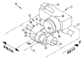
FIG. 5 is a perspective view showing the
図6は、発電ユニット11と駆動ユニット12とを示す側面図である。図6に示すように駆動ユニット12は、電動機22を覆う第1部61がデファレンシャル23を覆う第3部65よりも大径である。駆動ユニット12は、第3部65の少なくとも一部、例えば車両10の高さ方向での上部65aが発電カバー66の下に重なるように配置されている。つまり、車両10の高さ方向において、電動機22に対して発電機20を一部が重なるように配置している。このため、駆動ユニット12をエンジンルーム17内の車両10の下方に寄せて配置でき、よってエンジンルーム17の車両10の高さ方向での小型化を図ることができる。また、第1部61よりも第3部65の径の方が小さいので、エンジン19をエンジンルーム17内における低い位置に載せることができる。
FIG. 6 is a side view showing the
図7は、充電器14およびインバータユニット15を示す。図7に示すようにエンジンルーム17は、水平式のエンジン19を配置したため、エンジン19とボンネット68(図6参照)との間にスペースが空く。この実施形態では、ボンネット68との間のスペースに充電器14を配置している。充電器14は、例えば車両10の高さ方向の厚みが薄い直方体をした充電器カバー70を備えている。充電器カバー70は、車両10の前後方向に延びた箱形状になっており、吸気系43を除くエンジン19の上方の位置から発電機20の上方を覆うように配置されている。
FIG. 7 shows the
充電器カバー70の上面には、複数の放熱板72が設けられている。充電器14は、充電時に発熱し、充電器14から発熱した廃熱は、充電器カバー70の上面を介して放熱板72に伝導されて放熱される。充電器14がエンジンルーム17内のうちの上方に配置されているため、放熱板72の放熱の効果が向上する。また、廃熱によりエンジンルーム17を暖気することができる。なお、廃熱を利用して浄化触媒を暖機するように構成してもよい。この場合には、例えば排気系44を充電器14の周囲、例えばエンジン19の上に配置してもよい。
A plurality of
エンジンルーム17の側面には、充電用インレット39が設けられている。充電用インレット39には、外部電源に接続するための充電ケーブル(図示なし)が接続される。充電器14は、交流給電線73を介して充電用インレット39と接続されている。この実施形態では、充電器14をエンジンルーム17の上方に配置したから、短い交流給電線73で配線でき、また配線の取り回しがし易くなる。
A charging
図8は、発電ユニット11とインバータユニット15とを示す。図8に示すように、インバータユニット15は、防水および電磁シールド確保などを目的として、例えば直方体をしたインバータカバー74を備えている。また、インバータユニット15は、インバータ37やコンバータ38を冷却するための放熱板75(図7参照)などを内部に備える。このため、インバータユニット15は、サイズが大型化している。つまり、充電器14よりも厚みが嵩張った直方体の外形輪郭である。
FIG. 8 shows the
エンジン19は、車両10の上面から見て、外形を包含するように簡略化した輪郭が車幅方向に長い直方体である。発電機20は、外形輪郭が円筒軸線を車両10の前後方向に沿わせた円筒体である。つまり、エンジン19と発電機20とは、車両10の上方から見て、例えばクランク軸41の軸心41aと回転軸49の軸心49aとが結ばれてL字状をなす一点鎖線Cに沿う外形輪郭になる。そして、エンジン19は、発電機20よりも車両10の前方に配置されている。このため、インバータユニット15は、エンジン19と発電機20との輪郭外形がなすL字状の内側に、長手方向を車幅方向に沿わした姿勢で配置されている。インバータカバー74には、インバータユニット15とバッテリ16とを接続するハーネス、インバータユニット15と発電機20とを接続するハーネス、およびインバータユニット15と発電機20とを接続するハーネス(いずれも図示なし)などが接続される。インバータユニット15は、発電機20および電動機22の近くに配置されている。このため、この実施形態では、短いハーネスを使用することができ、また配線の取り回しがし易くなる。
The
なお、図8では、車両10の上面から見て、エンジン19に対して車幅方向の右側に寄せて発電機20を配置してL字状を構成しているが、発電機20をエンジン19に対して車幅方向の左側に寄せてL字状を構成してよい。
In FIG. 8, when viewed from the top surface of the
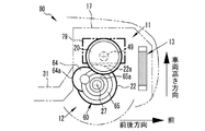
図9は、エンジン19に対して車幅方向の左側に寄せて発電機20を配置した実施形態を示す。図9に示すようにエンジン19は、外形を包含するように簡略化した輪郭が車両10の上から見て長辺を車幅方向に沿わせた姿勢の長い直方体である。発電機20は、エンジン19に対して車幅方向の左側に寄せて配置されている。発電機20は、回転軸49がクランク軸41と同軸上に、かつエンジン19の車両10の前後方向での後にエンジン19に接近して配置されている。この実施形態では、電動機22の少なくとも一部、例えば車軸27を中心とする外周のうちの上方かつ前方寄りの略上部22aが発電機20の下に重なるように配置されている。また、この実施形態では、エンジン19の下方および駆動ユニット12の車幅方向における右方にスペースが生じる。このため、右方に生じたスペースを利用して排気系44のうちの排気管87を車両10の後方に向けて配置することができる。なお、図9では、図1ないし図8で説明した部材と同じまたは同様な部材には同符号を付与してここでは詳しい説明を省略する。
FIG. 9 shows an embodiment in which the
また、図9で説明した実施形態では、車両10の上面から見て、エンジン19を発電機20の車両10の前後方向での前に配置しているが、これに限らず、エンジン19を発電機20よりも後に配置してもよい。
Further, in the embodiment described with reference to FIG. 9, the
以上、上記で説明した各実施形態はこの発明の例示であり、上述した各実施形態に限定されないのであって、この発明の目的を逸脱しない範囲で適宜に変更することができる。 Each embodiment described above is an exemplification of the present invention, and is not limited to each embodiment described above, and can be appropriately changed without departing from the object of the present invention.
例えば上記各実施形態では、キャビン18の前方にエンジンルーム17を配置しているが、キャビン18の後方にエンジンルーム17を配置してもよい。この場合には、車両10の後輪が駆動輪になる。
For example, in each of the above embodiments, the
また、上記各実施形態では、単気筒のエンジン19として説明しているが、この発明ではこれに限らず、多気筒のエンジンであってもよい。
In each of the above-described embodiments, the single-
図10は、多気筒のエンジン89を使用した実施形態を示す平面図である。図10に示すようにエンジン89は、2気筒のレスプロエンジンであり、第1ピストン91および第2ピストン92を有する。第1ピストン91および第2ピストン92は、車両10の前後方向に並んで配置されている。エンジン89は、車載状態にて、第1ピストン91が往復動する第1シリンダ93と、第2ピストン92が往復動する第2シリンダ94とを有する。第1シリンダ93と第2シリンダ94とは、クランク軸41を挟んで車幅方向での左方に配置されている。エンジン19は、縦置き姿勢で搭載されている。電動機22の少なくとも一部、例えば略上部22aは、エンジン89の下、例えば第1シリンダ93および第2シリンダ94を内蔵するブロック95の下に重なるように配置されている。また第3部65の少なくとも一部、例えば上部65aは、発電機20の下に重なるように配置されている。
FIG. 10 is a plan view showing an embodiment in which a
図11は、図10で説明したエンジン89を示す。図11では、エンジン89のブロック95の内部を模式的に示している。図11に示すようにエンジン89は、車両90の後方から見て、第1シリンダ93および第2シリンダ94のバンク角が、例えば90度よりも小さい角度になっている狭角V型のエンジンである。このエンジン89は、車載状態にて第1ピストン91が第1シリンダ93内を往復動する方向が水平方向に配置される。そして第2ピストン92が第2シリンダ94内を往復道する方向は、クランク軸41を中心として第1シリンダ93をバック角の分だけ上に向けて回転させた方向となる。つまり、エンジン89は、第1シリンダ93および第2シリンダ94を覆うブロック95の下部95aが水平方向にフラットになっている。これにより、ブロック95の下部95aの下に重ねて電動機22の少なくとも一部、例えば略上部22aを配置することが可能となる。また、第1シリンダ93および第2シリンダ94は、エンジン89の車両90の前後方向でのサイズを短縮するために、車両10の上面から見て、第2シリンダ94の一部94aが第1シリンダ93の一部93aに重なるように配列されている(図10参照)。
FIG. 11 shows the
上記各実施形態では、エンジン19を水平式で、かつ縦置き姿勢に搭載しているが、この発明ではこれに限らず、車載状態にてピストン40がシリンダ内を往復動する方向が垂直方向に配置される垂直式のレシプロエンジンとしてよい。また、エンジン19は、クランク軸41が車幅方向と平行となる横置き姿勢で設置されていてよい。
In each of the above embodiments, the
図12は、垂直式のエンジン77を横置きに搭載した実施形態の車両76を示す。図13は、図12の車両76を示す側面図である。図12および図13に示すように、エンジン77は、垂直式のレシプロエンジンとなっており、クランク軸41が車幅方向と平行になる横置き姿勢でエンジンルーム17に搭載されている。発電機20は、回転軸49がクランク軸41と同軸上で、かつエンジン77に接近して配置されている。電動機22は、出力軸50が車軸27と同軸上に配置されており、また出力軸50が発電機20の回転軸49と平行方向または平行に近い方向になるように配置されている。そして、電動機22は、少なくとも一部、例えば略上部22aがエンジン77の下に重なるように配置されている。つまり、発電カバー66の外径から発電機20の回転軸49の軸中心までの径方向の長さrは、エンジン77の下部(排気系44を除く)からクランク軸41の軸中心までの車両高さ方向における長さhよりも長い。また、車軸27の軸中心から第1部61の外径までの径方向の長さR1は、車軸27の軸中心から第3部65の外径までの径方向の長さR2よりも長い。このため、エンジン77をエンジンルーム17内における低い位置に載せられる。また、デファレンシャル23を覆う第3部65は、少なくとも一部、例えば上部65aが発電機20の下に重なるように配置されている。そして、減速機24を覆う凸部64の少なくとも一部、例えば後部64aは、センタートンネル31内に入り込んでいる。なお、図12および図13では、図1から図8で説明したと同じまたは同様な部材に同符号を付与してここでは詳しい説明を省略する。
FIG. 12 shows a
図14は、水平式のエンジン79を横置きに搭載した実施形態の車両80を示す斜視図である。図15は、図14の車両80を示す側面図である。図14および図15に示すようにエンジン79は、水平式のレシプロエンジンとなっており、横置き姿勢でエンジンルーム17に搭載されている。発電機20は、回転軸49がクランク軸41と同軸上に、かつエンジン79に接近して配置される。電動機22は、少なくとも一部、例えば略上部22aがエンジン79の下に重なるように配置されている。また、第3部65は、少なくとも一部、例えば上部65aが発電機20の下に重なるように配置されている。そして、凸部64の少なくとも一部、例えば後部64aは、センタートンネル31内に入り込んでいる。この実施形態では、図12で説明したと同じまたは同様に、発電カバー66の外径から発電機20の回転軸49の軸中心までの径方向の長さがエンジン79の下部(排気系44を除く)からクランク軸41の軸中心までの車両高さ方向における長さよりも長い。また、車軸27の軸中心から第1部61の外径までの径方向の長さが車軸27の軸中心から第3部65の外径までの径方向の長さよりも長い。このため、エンジン79をエンジンルーム17内における低い位置に載せられる。なお、図14および図15では、図1から図8で説明したと同じまたは同様な部材に同符号を付与してここでは詳しい説明を省略する。
FIG. 14 is a perspective view showing a
図16は、垂直式のエンジン82を縦置きに搭載した実施形態の車両83を示す斜視図である。図17は、図16の車両83を示す側面図である。図16および図17に示すようにエンジン82は、垂直式のレシプロエンジンとなっており、クランク軸41が車両83の前後方向と平行になる縦置き姿勢でエンジンルーム17に搭載されている。発電機20は、回転軸49がクランク軸41と同軸上で、かつエンジン82の車両10の前後方向での後にエンジン82に接近して配置されている。駆動ハウジング60の第3部65は、少なくとも一部、例えば上部65aが発電機20の下に重なるように配置されている。そして、凸部64は、少なくとも一部、例えば後部64aがセンタートンネル31に入り込んでいる。なお、図16および図17では、図1から図8で説明したと同じまたは同様な部材に同符号を付与してここでは詳しい説明を省略する。
FIG. 16 is a perspective view showing a
以上、上記で説明した各実施形態は本発明の例示であり、ある実施形態に特有の構造および機能は他の実施形態にも適用できる。また、本発明は、上述した各実施形態に限定されないのであって、本発明の目的を逸脱しない範囲で適宜に変更することができる。例えば上記各実施形態では、電動機22の出力軸50を車幅方向と平行に配置しているが、この発明ではこれに限らず、電動機22の出力軸50を車幅方向と直交に配置したFR方式としてもよい。
As mentioned above, each embodiment described above is an illustration of the present invention, and the structure and function peculiar to a certain embodiment can be applied to other embodiments. Further, the present invention is not limited to the above-described embodiments, and can be appropriately changed without departing from the object of the present invention. For example, in each of the above embodiments, the
10,76,80,83,90…車両、 14…充電器、 15…インバータユニット、 17…エンジンルーム、 19…エンジン、 20…発電機、 22…電動機、 23…デファレンシャル、 24…減速機、 29…フロアパネル、 31…センタトンネル、 40…ピストン、 41…クランク軸、 49…回転軸、 50…出力軸、 64…凸部。 10, 76, 80, 83, 90 ... vehicle, 14 ... charger, 15 ... inverter unit, 17 ... engine room, 19 ... engine, 20 ... generator, 22 ... electric motor, 23 ... differential, 24 ... speed reducer, 29 ... Floor panel, 31 ... Center tunnel, 40 ... Piston, 41 ... Crank shaft, 49 ... Rotating shaft, 50 ... Output shaft, 64 ... Projection.
Claims (8)
前記発電機は、前記トルクが伝達される回転軸を有し、前記回転軸が前記車両の前後方向に平行になるように配置され、かつ前記エンジンに対して前記車両の前後方向における後方に配置され、
前記電動機は、前記走行用駆動トルクを出力する出力軸を有し、前記出力軸が前記車両の幅方向に平行になるように配置され、
前記電動機を覆う駆動ハウジングと、
前記発電機を覆う発電カバーとを有し、
前記駆動ハウジングの少なくとも一部は、前記発電カバーの下に重なるように配置されており、
更に前記バッテリから出力される直流電流を前記電動機用の交流電流に変換するインバータを備え、
前記車両の上面から見て、輪郭外形を包含するように簡略化した形状が前記車両の幅方向に長辺を沿わせた姿勢の直方体である前記エンジンと、輪郭外形を包含するように簡略した形状が前記車両の前後方向に円筒軸を沿わせた姿勢の円筒体である前記発電機とを合わせた外形輪郭がL字状に配置されており、
前記エンジンと前記発電機との外形輪郭が作るL字状の間に、前記インバータが配置されている
ことを特徴とする車両。 Charging the engine that outputs torque by burning the air-fuel mixture in the cylinder, the generator that generates power by being rotated by the torque, and the electric power generated by the generator or the electric power generated by the generator In a vehicle provided with an electric motor that outputs driving torque by driving using electric power stored in a battery,
The generator has a rotating shaft to which the torque is transmitted, and is disposed so that the rotating shaft is parallel to the front-rear direction of the vehicle, and is disposed rearward in the front-rear direction of the vehicle with respect to the engine. And
The electric motor has an output shaft that outputs the driving torque for traveling, and the output shaft is arranged to be parallel to the width direction of the vehicle,
A drive housing covering the electric motor;
A power generation cover covering the generator,
At least a part of the drive housing is arranged to overlap the power generation cover,
Furthermore, an inverter for converting a direct current output from the battery into an alternating current for the electric motor is provided,
The engine, which is a rectangular parallelepiped with a long side along the width direction of the vehicle, is simplified so as to include the contour outline as seen from the top surface of the vehicle. The outer shape combined with the generator, which is a cylindrical body in a posture in which the shape is aligned with the cylindrical axis in the longitudinal direction of the vehicle, is arranged in an L shape,
The vehicle, wherein the inverter is arranged between an L shape formed by an outer contour of the engine and the generator .
前記エンジンは、前記トルクを出力するクランク軸を有し、前記クランク軸が前記車両の前後方向と平行に、かつ前記クランク軸が前記発電機の前記回転軸と同軸上に配置されており、
前記走行用駆動トルクを駆動輪に伝達する車軸を有し、かつ前記車軸を前記出力軸と同軸上に配置し、かつ前記走行用駆動トルクを前記車軸に伝達するデファレンシャルを更に備え、
前記駆動ハウジングは、前記電動機を覆う第1ケースと、前記第1ケースに対して前記車両の幅方向に並べて配置され、かつ前記デファレンシャルを覆う第2ケースとを有し、前記第2ケースが前記第1ケースよりも前記車軸を中心とする外周が小径となっており、前記第2ケースの少なくとも一部は、前記発電カバーの下に重なるように配置されており、
前記発電カバーの下部は、前記車両の側面から視て前記第1ケースに重なるように配置されている
ことを特徴とする車両。 The vehicle according to claim 1,
The engine has a crankshaft that outputs the torque, the crankshaft is arranged in parallel with the longitudinal direction of the vehicle, and the crankshaft is arranged coaxially with the rotating shaft of the generator,
The vehicle further comprises an axle for transmitting the driving torque for driving to driving wheels; the axle is disposed coaxially with the output shaft; and a differential for transmitting the driving torque for driving to the axle;
The drive housing includes a first case that covers the electric motor, and a second case that is arranged in the width direction of the vehicle with respect to the first case and covers the differential, and the second case is the The outer periphery centering on the axle is smaller than the first case, and at least a part of the second case is disposed so as to overlap the power generation cover,
The vehicle, wherein a lower portion of the power generation cover is disposed so as to overlap the first case as viewed from a side surface of the vehicle.
前記エンジンは、前記気筒内に設けたシリンダと、前記シリンダ内を往復動するピストンとを有し、車載状態にて前記ピストンが前記シリンダ内を往復動する方向が鉛直線に対して所定角度で交差する向きに配置される水平式のエンジンであり、
前記電動機は、前記デファレンシャルに対して前記ピストンの上死点側に配置されている
ことを特徴とする車両。 The vehicle according to claim 2, wherein
The engine includes a cylinder provided in the cylinder and a piston that reciprocates within the cylinder, and a direction in which the piston reciprocates within the cylinder in a vehicle-mounted state is a predetermined angle with respect to a vertical line. It is a horizontal engine that is arranged in an intersecting direction,
The vehicle, wherein the electric motor is arranged on a top dead center side of the piston with respect to the differential .
前記エンジンには、前記車両の高さ方向の上方に吸気系が、下方に排気系がそれぞれ設けられている
ことを特徴とする車両。 The vehicle according to claim 3 , wherein
The vehicle, wherein the engine is provided with an intake system above the vehicle in the height direction and an exhaust system below .
前記車両に設けられたキャビンと、前記キャビン内に前記車両の前後方向に延びて配置されたセンタートンネルと、前記出力軸から伝達される前記走行用駆動トルクを前記デファレンシャルに伝達する減速機と、前記第1ケースと前記第2ケースとの間で前記車両の後方かつ上方に向けて突出して配置され、かつ前記減速機を覆う第3ケースとを有し、
前記第3ケースは、少なくとも一部が前記センタートンネル内に入り込んでいる
ことを特徴とする車両。 In the vehicle according to any one of claims 2 to 4,
A cabin provided in the vehicle; a center tunnel disposed in the cabin extending in the front-rear direction of the vehicle; and a speed reducer that transmits the driving torque transmitted from the output shaft to the differential. A third case disposed between the first case and the second case so as to protrude rearward and upward of the vehicle and covering the reduction gear;
The vehicle according to claim 3, wherein at least a part of the third case enters the center tunnel .
外部電源から電力を受けて前記バッテリを充電する充電器を有し、前記充電器が前記エンジンの上に配置されている
ことを特徴とする車両。 In the vehicle according to any one of claims 1 to 5 ,
A vehicle including a charger that receives power from an external power source to charge the battery, and the charger is disposed on the engine .
前記エンジンは、前記気筒に設けたシリンダ内を往復動するピストンと、前記ピストンの往復動により前記トルクを出力するクランク軸とを有し、
前記発電機は、前記トルクが伝達される回転軸を有し、前記回転軸が前記クランク軸と同軸上に配置されており、
前記電動機は、前記走行用駆動トルクを出力する出力軸を有し、
前記走行用駆動トルクを駆動輪に伝達する車軸を有し、かつ前記車軸を前記出力軸と同軸上に配置したデファレンシャルと、
前記発電機を覆う発電カバーと、
前記電動機を覆う第1ケースと、
前記第1ケースに対して前記車両の幅方向に並べて配置され、かつ前記デファレンシャルを覆う第2ケースと、
前記バッテリから出力される直流電流を前記電動機用の交流電流に変換するインバータとを備え、
前記第2ケースは、前記第1ケースよりも前記車軸を中心とする外周が小径となっており、
前記第2ケースの一部は、前記発電カバーの下に重なるように配置されており、
前記電動機は、前記デファレンシャルに対して前記ピストンの上死点側に配置されており、
前記車両の上面から見て、輪郭外形を包含するように簡略化した形状が前記車両の幅方向に長辺を沿わせた姿勢の直方体である前記エンジンと、輪郭外形を包含するように簡略した形状が前記車両の前後方向に円筒軸を沿わせた姿勢の円筒体である前記発電機とを合わせた外形輪郭がL字状に配置されており、
前記エンジンと前記発電機との外形輪郭が作るL字状の間に、前記インバータが配置されている
ことを特徴とする車両。 Charging the engine that outputs torque by burning the air-fuel mixture in the cylinder, the generator that generates power by being rotated by the torque, and the electric power generated by the generator or the electric power generated by the generator In a vehicle provided with an electric motor that outputs driving torque by driving using electric power stored in a battery,
The engine has a piston that reciprocates in a cylinder provided in the cylinder, and a crankshaft that outputs the torque by the reciprocating motion of the piston,
The generator has a rotating shaft to which the torque is transmitted, and the rotating shaft is arranged coaxially with the crankshaft,
The electric motor has an output shaft that outputs the driving torque for traveling,
A differential having an axle for transmitting the driving torque for driving to drive wheels, and the axle arranged coaxially with the output shaft;
A power generation cover covering the generator;
A first case covering the electric motor;
A second case arranged side by side in the width direction of the vehicle with respect to the first case and covering the differential;
An inverter that converts a direct current output from the battery into an alternating current for the electric motor,
The second case has a smaller outer diameter around the axle than the first case,
A part of the second case is arranged to overlap under the power generation cover,
The electric motor is disposed on the top dead center side of the piston with respect to the differential,
The engine, which is a rectangular parallelepiped with a long side along the width direction of the vehicle, is simplified so as to include the contour outline as seen from the top surface of the vehicle. The outer shape combined with the generator, which is a cylindrical body in a posture in which the shape is aligned with the cylindrical axis in the longitudinal direction of the vehicle, is arranged in an L shape,
The vehicle, wherein the inverter is arranged between an L shape formed by an outer contour of the engine and the generator .
前記エンジンは、前記車両の前後方向における前記発電機の前に配置されている The engine is disposed in front of the generator in the longitudinal direction of the vehicle.
ことを特徴とする車両。A vehicle characterized by that.
Priority Applications (13)
| Application Number | Priority Date | Filing Date | Title |
|---|---|---|---|
| JP2017021983A JP6249115B1 (en) | 2017-02-09 | 2017-02-09 | vehicle |
| PH12018000030A PH12018000030A1 (en) | 2017-02-09 | 2018-01-30 | Vehicle |
| RU2018104260A RU2664136C1 (en) | 2017-02-09 | 2018-02-05 | Vehicle |
| TW107103980A TWI652185B (en) | 2017-02-09 | 2018-02-05 | vehicle |
| MYPI2018700475A MY177302A (en) | 2017-02-09 | 2018-02-06 | Vehicle |
| US15/890,902 US10399428B2 (en) | 2017-02-09 | 2018-02-07 | Vehicle |
| BR102018002618A BR102018002618A2 (en) | 2017-02-09 | 2018-02-07 | vehicle |
| MX2018001677A MX2018001677A (en) | 2017-02-09 | 2018-02-08 | Vehicle. |
| KR1020180015528A KR101877704B1 (en) | 2017-02-09 | 2018-02-08 | Vehicle |
| CA2994323A CA2994323C (en) | 2017-02-09 | 2018-02-08 | Vehicle |
| EP18156168.9A EP3360710B1 (en) | 2017-02-09 | 2018-02-09 | Vehicle |
| CN201810130913.3A CN108407600B (en) | 2017-02-09 | 2018-02-09 | Vehicle |
| ES18156168T ES2813083T3 (en) | 2017-02-09 | 2018-02-09 | Vehicle |
Applications Claiming Priority (1)
| Application Number | Priority Date | Filing Date | Title |
|---|---|---|---|
| JP2017021983A JP6249115B1 (en) | 2017-02-09 | 2017-02-09 | vehicle |
Publications (2)
| Publication Number | Publication Date |
|---|---|
| JP6249115B1 true JP6249115B1 (en) | 2017-12-20 |
| JP2018127124A JP2018127124A (en) | 2018-08-16 |
Family
ID=60685644
Family Applications (1)
| Application Number | Title | Priority Date | Filing Date |
|---|---|---|---|
| JP2017021983A Active JP6249115B1 (en) | 2017-02-09 | 2017-02-09 | vehicle |
Country Status (13)
| Country | Link |
|---|---|
| US (1) | US10399428B2 (en) |
| EP (1) | EP3360710B1 (en) |
| JP (1) | JP6249115B1 (en) |
| KR (1) | KR101877704B1 (en) |
| CN (1) | CN108407600B (en) |
| BR (1) | BR102018002618A2 (en) |
| CA (1) | CA2994323C (en) |
| ES (1) | ES2813083T3 (en) |
| MX (1) | MX2018001677A (en) |
| MY (1) | MY177302A (en) |
| PH (1) | PH12018000030A1 (en) |
| RU (1) | RU2664136C1 (en) |
| TW (1) | TWI652185B (en) |
Cited By (2)
| Publication number | Priority date | Publication date | Assignee | Title |
|---|---|---|---|---|
| JP2017035920A (en) * | 2015-08-07 | 2017-02-16 | 株式会社デンソー | Driving apparatus of vehicle |
| CN111801235A (en) * | 2018-03-09 | 2020-10-20 | 丰田自动车株式会社 | Wheel axle structure |
Families Citing this family (10)
| Publication number | Priority date | Publication date | Assignee | Title |
|---|---|---|---|---|
| JP2021010269A (en) * | 2019-07-02 | 2021-01-28 | 本田技研工業株式会社 | Drive unit and vehicle |
| GB2601707B (en) * | 2019-12-26 | 2023-03-08 | Aisin Corp | Vehicle drive apparatus |
| JP2021138317A (en) * | 2020-03-06 | 2021-09-16 | トヨタ自動車株式会社 | Vehicle unit mounting structure |
| CN113103855B (en) * | 2020-10-13 | 2023-01-10 | 东风越野车有限公司 | Hybrid vehicle frame, power system and vehicle |
| DE102020007296A1 (en) | 2020-11-30 | 2022-06-02 | Daimler Ag | Hybrid transmission for a vehicle |
| US11912132B2 (en) | 2020-11-30 | 2024-02-27 | Mercedes-Benz Group AG | Hybrid transmission for a vehicle |
| US11926220B2 (en) * | 2020-11-30 | 2024-03-12 | Mercedes-Benz Group AG | Hybrid transmission for a vehicle |
| CN214728144U (en) * | 2021-03-15 | 2021-11-16 | 赛格威科技有限公司 | Hybrid all-terrain vehicle |
| JP7357044B2 (en) * | 2021-12-17 | 2023-10-05 | ヤマハ発動機株式会社 | Series hybrid engine drive power supply unit and electric mobile object |
| WO2023119553A1 (en) * | 2021-12-23 | 2023-06-29 | 日産自動車株式会社 | Hybrid vehicle |
Citations (9)
| Publication number | Priority date | Publication date | Assignee | Title |
|---|---|---|---|---|
| JPH1199834A (en) * | 1997-09-29 | 1999-04-13 | Daihatsu Motor Co Ltd | Power device loading structure of hybrid powered vehicle |
| JP2008207570A (en) * | 2007-02-23 | 2008-09-11 | Mazda Motor Corp | Control device of series hybrid vehicle |
| JP2009001049A (en) * | 2007-06-19 | 2009-01-08 | Mazda Motor Corp | Battery control device for vehicle |
| JP2011143827A (en) * | 2010-01-14 | 2011-07-28 | Mazda Motor Corp | Vehicle structure of electric vehicle |
| JP2013067247A (en) * | 2011-09-21 | 2013-04-18 | Nippon Soken Inc | Charging apparatus for vehicle |
| JP2013082339A (en) * | 2011-10-11 | 2013-05-09 | Suzuki Motor Corp | Driving device for hybrid vehicle |
| JP2014118040A (en) * | 2012-12-17 | 2014-06-30 | Suzuki Motor Corp | Power mechanism for hybrid vehicle |
| JP2016173086A (en) * | 2015-03-18 | 2016-09-29 | 富士重工業株式会社 | Discharge device of lubricating oil |
| JP2017001542A (en) * | 2015-06-11 | 2017-01-05 | マツダ株式会社 | Driving device of vehicle |
Family Cites Families (16)
| Publication number | Priority date | Publication date | Assignee | Title |
|---|---|---|---|---|
| US2915133A (en) * | 1954-07-02 | 1959-12-01 | Daimler Benz Ag | Vehicle having four-wheel drive with offset flywheel |
| JPS5824289B2 (en) * | 1977-07-27 | 1983-05-20 | トヨタ自動車株式会社 | Automotive drive unit |
| JPS608051B2 (en) | 1979-02-20 | 1985-02-28 | 日産フエロ有機化学株式会社 | Halogenated resin composition |
| JP2000185567A (en) * | 1998-12-24 | 2000-07-04 | Toyota Motor Corp | Hybrid power plant |
| JP3843702B2 (en) * | 2000-06-09 | 2006-11-08 | アイシン・エィ・ダブリュ株式会社 | Driving device for driving electric vehicle |
| US20050107198A1 (en) * | 2003-11-19 | 2005-05-19 | Henryk Sowul | Hybrid powertrain |
| US20050205329A1 (en) * | 2004-02-25 | 2005-09-22 | Shimon Fanger-Vexler | Vehicle and vehicle drive-through suspension arm |
| US8011341B2 (en) * | 2006-11-21 | 2011-09-06 | Toyota Jidosha Kabushiki Kaisha | Vehicle engine structure |
| US9074527B2 (en) * | 2010-01-04 | 2015-07-07 | Del Wolverton | Counterpoise engine |
| US9199537B2 (en) * | 2011-07-26 | 2015-12-01 | Toyota Jidosha Kabushiki Kaisha | Automobile with vehicle drive motor |
| JP5900023B2 (en) * | 2012-03-02 | 2016-04-06 | 三菱自動車工業株式会社 | Transaxle device for hybrid vehicles |
| JP5929435B2 (en) | 2012-04-04 | 2016-06-08 | スズキ株式会社 | Hybrid vehicle power unit |
| WO2015008581A1 (en) * | 2013-07-18 | 2015-01-22 | 日産自動車株式会社 | Hybrid vehicle |
| JP6199102B2 (en) | 2013-07-19 | 2017-09-20 | 本田技研工業株式会社 | Engine generator |
| JP2016132326A (en) * | 2015-01-16 | 2016-07-25 | トヨタ自動車株式会社 | Electric vehicle, holding mechanism, and electric vehicle manufacturing method |
| US9944166B2 (en) * | 2015-03-09 | 2018-04-17 | Ford Global Technologies, Llc | Axle assembly for hybrid electric vehicle |
-
2017
- 2017-02-09 JP JP2017021983A patent/JP6249115B1/en active Active
-
2018
- 2018-01-30 PH PH12018000030A patent/PH12018000030A1/en unknown
- 2018-02-05 TW TW107103980A patent/TWI652185B/en not_active IP Right Cessation
- 2018-02-05 RU RU2018104260A patent/RU2664136C1/en not_active IP Right Cessation
- 2018-02-06 MY MYPI2018700475A patent/MY177302A/en unknown
- 2018-02-07 US US15/890,902 patent/US10399428B2/en active Active
- 2018-02-07 BR BR102018002618A patent/BR102018002618A2/en not_active IP Right Cessation
- 2018-02-08 MX MX2018001677A patent/MX2018001677A/en unknown
- 2018-02-08 CA CA2994323A patent/CA2994323C/en not_active Expired - Fee Related
- 2018-02-08 KR KR1020180015528A patent/KR101877704B1/en active IP Right Grant
- 2018-02-09 ES ES18156168T patent/ES2813083T3/en active Active
- 2018-02-09 CN CN201810130913.3A patent/CN108407600B/en active Active
- 2018-02-09 EP EP18156168.9A patent/EP3360710B1/en active Active
Patent Citations (9)
| Publication number | Priority date | Publication date | Assignee | Title |
|---|---|---|---|---|
| JPH1199834A (en) * | 1997-09-29 | 1999-04-13 | Daihatsu Motor Co Ltd | Power device loading structure of hybrid powered vehicle |
| JP2008207570A (en) * | 2007-02-23 | 2008-09-11 | Mazda Motor Corp | Control device of series hybrid vehicle |
| JP2009001049A (en) * | 2007-06-19 | 2009-01-08 | Mazda Motor Corp | Battery control device for vehicle |
| JP2011143827A (en) * | 2010-01-14 | 2011-07-28 | Mazda Motor Corp | Vehicle structure of electric vehicle |
| JP2013067247A (en) * | 2011-09-21 | 2013-04-18 | Nippon Soken Inc | Charging apparatus for vehicle |
| JP2013082339A (en) * | 2011-10-11 | 2013-05-09 | Suzuki Motor Corp | Driving device for hybrid vehicle |
| JP2014118040A (en) * | 2012-12-17 | 2014-06-30 | Suzuki Motor Corp | Power mechanism for hybrid vehicle |
| JP2016173086A (en) * | 2015-03-18 | 2016-09-29 | 富士重工業株式会社 | Discharge device of lubricating oil |
| JP2017001542A (en) * | 2015-06-11 | 2017-01-05 | マツダ株式会社 | Driving device of vehicle |
Cited By (3)
| Publication number | Priority date | Publication date | Assignee | Title |
|---|---|---|---|---|
| JP2017035920A (en) * | 2015-08-07 | 2017-02-16 | 株式会社デンソー | Driving apparatus of vehicle |
| CN111801235A (en) * | 2018-03-09 | 2020-10-20 | 丰田自动车株式会社 | Wheel axle structure |
| CN111801235B (en) * | 2018-03-09 | 2023-09-29 | 丰田自动车株式会社 | Wheel axle structure |
Also Published As
| Publication number | Publication date |
|---|---|
| TW201836876A (en) | 2018-10-16 |
| BR102018002618A2 (en) | 2018-10-30 |
| EP3360710B1 (en) | 2020-07-22 |
| CN108407600A (en) | 2018-08-17 |
| CA2994323C (en) | 2018-08-28 |
| TWI652185B (en) | 2019-03-01 |
| CA2994323A1 (en) | 2018-04-13 |
| RU2664136C1 (en) | 2018-08-15 |
| KR101877704B1 (en) | 2018-07-12 |
| MY177302A (en) | 2020-09-11 |
| US10399428B2 (en) | 2019-09-03 |
| MX2018001677A (en) | 2019-04-29 |
| CN108407600B (en) | 2019-07-30 |
| PH12018000030A1 (en) | 2019-04-15 |
| JP2018127124A (en) | 2018-08-16 |
| US20180222307A1 (en) | 2018-08-09 |
| EP3360710A1 (en) | 2018-08-15 |
| ES2813083T3 (en) | 2021-03-22 |
Similar Documents
| Publication | Publication Date | Title |
|---|---|---|
| JP6249115B1 (en) | vehicle | |
| JP5418116B2 (en) | Rear structure of electric vehicle equipped with engine | |
| JP2013180680A (en) | Transaxle device for hybrid vehicle | |
| WO2010095610A1 (en) | Hybrid electric vehicle | |
| JP5761009B2 (en) | Hybrid vehicle | |
| US8403096B2 (en) | Rear vehicle body structure of vehicle | |
| CN107107729B (en) | Hybrid vehicle and generator set | |
| WO2018079615A1 (en) | Vehicle | |
| JP2011073582A (en) | Front structure of engine-mounted electric vehicle | |
| JP5499730B2 (en) | Electric vehicle front structure | |
| JP5391974B2 (en) | Rear structure of electric vehicle equipped with engine | |
| US9714606B2 (en) | Vehicle power generating apparatus | |
| JPWO2021111809A5 (en) | ||
| JP2010000861A (en) | Inverter mounting structure of hybrid vehicle | |
| JP2012001127A (en) | Driving apparatus for hybrid vehicle | |
| JP2015008595A (en) | Machinery and electricity integrated drive apparatus for electrically-driven vehicle | |
| WO2023119553A1 (en) | Hybrid vehicle | |
| CN112648065B (en) | Vehicle with a steering wheel | |
| JP7281080B2 (en) | vehicle drive | |
| JP2007261467A (en) | Hybrid type vehicle | |
| JPWO2022162905A5 (en) | ||
| JP3727265B2 (en) | Electric car with gear motor | |
| JP2002500979A (en) | Electric transmission | |
| JP2011106301A (en) | Vehicle drive device | |
| JP2020168905A (en) | Industrial hybrid engine part structure |
Legal Events
| Date | Code | Title | Description |
|---|---|---|---|
| A02 | Decision of refusal |
Free format text: JAPANESE INTERMEDIATE CODE: A02 Effective date: 20170801 |
|
| TRDD | Decision of grant or rejection written | ||
| A01 | Written decision to grant a patent or to grant a registration (utility model) |
Free format text: JAPANESE INTERMEDIATE CODE: A01 Effective date: 20171024 |
|
| A61 | First payment of annual fees (during grant procedure) |
Free format text: JAPANESE INTERMEDIATE CODE: A61 Effective date: 20171106 |
|
| R151 | Written notification of patent or utility model registration |
Ref document number: 6249115 Country of ref document: JP Free format text: JAPANESE INTERMEDIATE CODE: R151 |