JP6245958B2 - IMAGING DEVICE, EXTERNAL DEVICE, IMAGING SYSTEM, IMAGING DEVICE CONTROL METHOD, EXTERNAL DEVICE CONTROL METHOD, IMAGING SYSTEM CONTROL METHOD, AND PROGRAM - Google Patents
IMAGING DEVICE, EXTERNAL DEVICE, IMAGING SYSTEM, IMAGING DEVICE CONTROL METHOD, EXTERNAL DEVICE CONTROL METHOD, IMAGING SYSTEM CONTROL METHOD, AND PROGRAM Download PDFInfo
- Publication number
- JP6245958B2 JP6245958B2 JP2013240990A JP2013240990A JP6245958B2 JP 6245958 B2 JP6245958 B2 JP 6245958B2 JP 2013240990 A JP2013240990 A JP 2013240990A JP 2013240990 A JP2013240990 A JP 2013240990A JP 6245958 B2 JP6245958 B2 JP 6245958B2
- Authority
- JP
- Japan
- Prior art keywords
- value
- imaging
- adjustment command
- optical path
- luminance
- Prior art date
- Legal status (The legal status is an assumption and is not a legal conclusion. Google has not performed a legal analysis and makes no representation as to the accuracy of the status listed.)
- Active
Links
Images


Landscapes
- Blocking Light For Cameras (AREA)
- Studio Devices (AREA)
Description
本発明は、撮像装置、外部装置、撮像システム、撮像装置の制御方法、外部装置の制御方法、撮像システムの制御方法、及びプログラムに関する。特に、赤外線遮断フィルタを撮像光学系の光路に挿脱する技術に用いられて好適である。 The present invention relates to an imaging apparatus, an external apparatus, an imaging system, an imaging apparatus control method, an external apparatus control method, an imaging system control method, and a program. In particular, it is suitable for use in a technique for inserting / removing an infrared blocking filter into / from the optical path of the imaging optical system.
従来、赤外線遮断フィルタを撮像光学系の光路から挿脱することにより、可視光撮像と赤外線撮像とを切り替えることができるように構成された撮像装置が知られている。ここで、可視光撮像とは、撮像光学系の光路に赤外線遮断フィルタが挿入された状態にて、撮像装置が被写体を撮像することを意味する。又、赤外線撮像とは、撮像光学系の光路から赤外線遮断フィルタが抜去された状態にて、撮像装置が被写体を撮像することを意味する。 2. Description of the Related Art Conventionally, there has been known an imaging apparatus configured to be able to switch between visible light imaging and infrared imaging by inserting and removing an infrared cutoff filter from an optical path of an imaging optical system. Here, visible light imaging means that the imaging device captures an image of a subject in a state where an infrared cut filter is inserted in the optical path of the imaging optical system. Infrared imaging means that the imaging device captures an image of the subject in a state where the infrared blocking filter is removed from the optical path of the imaging optical system.
特許文献1には、外界の明るさを判断することにより、撮像光学系の光路に対する赤外線遮断フィルタの挿脱を制御する撮像装置が開示されている。
また、ネットワーク技術の急速な普及とともに、外部装置からネットワーク経由で撮像装置を制御したいというユーザのニーズが高まっている。これは、撮像光学系の光路に対する赤外線遮断フィルタの挿脱制御も例外ではない。 In addition, with the rapid spread of network technology, there is an increasing need for users who want to control an imaging device from an external device via a network. This is no exception to the insertion / removal control of the infrared blocking filter with respect to the optical path of the imaging optical system.
しかしながら、上述の特許文献1では、撮像光学系の光路に対する赤外線遮断フィルタの挿脱制御に関する設定を外部装置からネットワーク経由で行うことは、想定されていなかった。更に、今後、このような設定として、撮像装置の被写体の輝度や撮像光学系の光路に対する赤外線遮断フィルタの挿脱に関する遅延時間等がユーザから望まれることも想定され得る。
However, in the above-described
ところが、外部装置からこのような設定が適切に行われるとは、限らない。そして、例えば、このような設定が適切に行われないと、撮像装置の被写体の輝度が低いにも関わらず、撮像光学系の光路に赤外線遮断フィルタが挿入されてしまい、撮像画像のこの被写体が黒潰れしてしまうことがあり得る。又、この輝度が高いにも関わらず、この光路から赤外線遮断フィルタが抜去されてしまい、撮像画像のこの被写体が白飛びしてしまうことがあり得る。 However, such settings are not always appropriately performed from an external device. For example, if such a setting is not properly performed, an infrared cut-off filter is inserted in the optical path of the imaging optical system even though the brightness of the subject of the imaging device is low. There is a possibility of black crushing. In addition, although the luminance is high, the infrared blocking filter may be removed from the optical path, and the subject in the captured image may be blown out.
本発明は、上述のような問題点に鑑みてなされたものである。即ち、撮像光学系の光路に対する赤外線遮断フィルタの挿脱に関する設定であって、外部装置により行われた設定に基づき、この挿脱を適切に制御することができる。又、撮像光学系の光路に対する赤外線遮断フィルタの挿脱に関する設定を、外部装置で適切に設定することができる。 The present invention has been made in view of the above problems. That is, it is a setting relating to the insertion / removal of the infrared cutoff filter with respect to the optical path of the imaging optical system, and this insertion / removal can be appropriately controlled based on the setting made by the external device. Moreover, the setting regarding the insertion / removal of the infrared cut-off filter with respect to the optical path of the imaging optical system can be appropriately set by an external device.
上記目的を達成するために、本発明の撮像装置は、外部装置とネットワーク経由で通信する撮像装置であって、撮像光学系と、前記撮像光学系により結像された被写体の像を撮像する撮像手段と、赤外線を遮断する赤外線遮断フィルタと、前記撮像光学系の光路に前記赤外線遮断フィルタを挿脱する挿脱手段と、前記被写体の輝度に関する輝度値が記述されることができる調整コマンドであって、前記赤外線遮断フィルタを前記光路に挿入する場合及び前記赤外線遮断フィルタを前記光路から抜去する場合のそれぞれについて前記輝度値が別々に記述されることができる調整コマンドを、前記外部装置からネットワーク経由で受信する受信手段と、前記受信手段で受信された調整コマンドにおいて別々に記述された輝度値を変換することにより、当該調整コマンドにおいて挿入する場合について記述された輝度値が変換された値を、当該調整コマンドにおいて抜去する場合について記述された輝度値が変換された値より、大きくする変換手段と、前記変換手段で変換された値に基づき、前記挿脱手段を制御する制御手段と、を備えることを特徴とする。 In order to achieve the above object, an imaging apparatus of the present invention is an imaging apparatus that communicates with an external device via a network, and that captures an imaging optical system and an image of a subject formed by the imaging optical system. An adjustment command that can describe a luminance value related to the brightness of the subject. And an infrared ray cutoff filter that blocks infrared rays; an insertion / removal means that inserts and removes the infrared cutoff filter in an optical path of the imaging optical system; Then, an adjustment command in which the brightness value can be described separately for each of the case where the infrared cutoff filter is inserted into the optical path and the case where the infrared cutoff filter is removed from the optical path is sent from the external device via the network. By converting the luminance value described separately in the receiving means received by the receiver and the adjustment command received by the receiving means. Conversion means for making a value obtained by converting the luminance value described in the case of insertion in the adjustment command larger than a value obtained by converting the luminance value described in the case of extracting in the adjustment command; and the conversion means And a control means for controlling the insertion / removal means based on the value converted in step (1).
本発明によれば、撮像光学系の光路に対する赤外線遮断フィルタの挿脱に関する設定であって、外部装置により行われた設定に基づき、この挿脱を適切に制御することができる。又、撮像光学系の光路に対する赤外線遮断フィルタの挿脱に関する設定を、外部装置で適切に設定することができる。 According to the present invention, it is a setting related to the insertion / removal of the infrared ray blocking filter with respect to the optical path of the imaging optical system, and this insertion / removal can be appropriately controlled based on the setting made by the external device. Moreover, the setting regarding the insertion / removal of the infrared cut-off filter with respect to the optical path of the imaging optical system can be appropriately set by an external device.
以下に、本発明の実施の形態について、図面を参照しながら詳細に説明する。なお、以下の実施例において示す構成は一例に過ぎず、本発明は、図示された構成に限定されるものではない。 Hereinafter, embodiments of the present invention will be described in detail with reference to the drawings. The configurations shown in the following embodiments are merely examples, and the present invention is not limited to the illustrated configurations.
また、以下の実施例におけるコマンドは、例えばOpen Network Video Interface Forum(以下ONVIFと称することがある)規格に基づいて定められているものとする。そして、ONVIF規格では、例えば、XML Schema Definition言語(以下、XSDと称することがある)を用いることにより、このコマンドの定義を行う。 In addition, the commands in the following embodiments are determined based on, for example, the Open Network Video Interface Forum (hereinafter sometimes referred to as ONVIF) standard. In the ONVIF standard, for example, this command is defined by using the XML Schema Definition language (hereinafter sometimes referred to as XSD).
(実施例1)
以下に、図1を参照して本実施例に係るネットワーク構成について説明する。より詳細には、図1は、本実施例に係る監視システムのシステム構成の一例を示す図である。
Example 1
The network configuration according to this embodiment will be described below with reference to FIG. More specifically, FIG. 1 is a diagram illustrating an example of a system configuration of the monitoring system according to the present embodiment.
本実施例における監視システムにおいて、撮像装置1000とクライアント装置2000とは、IPネットワーク網1500を介して(ネットワーク経由で)相互に通信可能な状態で接続される。これにより、撮像装置1000は、撮像画像をIPネットワーク網1500経由でクライアント装置2000に配信することができる。
In the monitoring system according to the present embodiment, the
なお、本実施例における撮像装置1000は、動画像を撮像する監視カメラであり、より詳細には、監視に用いられるネットワークカメラであるものとする。また、本実施例におけるクライアント装置2000は、PC等の外部装置の一例である。又、本実施例における監視システムは、撮像システムに相当する。
Note that the
また、IPネットワーク網1500は、例えばEthernet(登録商標)等の通信規格を満足する複数のルータ、スイッチ、ケーブル等から構成されるものとする。しかしながら、本実施例においては、撮像装置1000とクライアント装置2000との間の通信を行うことができるものであれば、その通信規格、規模、構成を問わない。
The
例えば、IPネットワーク網1500は、インターネットや有線LAN(Local Area Network)、無線LAN(Wireless LAN)、WAN(Wide Area Network)等により構成されていても良い。なお、本実施例における撮像装置1000は、例えば、PoE(Power Over Ethernet(登録商標))に対応していても良く、LANケーブルを介して電力を供給されても良い。
For example, the
クライアント装置2000は、撮像装置1000に対し、各種コマンドを送信する。これらのコマンドは、例えば、撮像装置1000の撮像方向及び画角を変更させるためのコマンド、撮像パラメータを変更するためのコマンド、撮像画像のストリーミングを開始させるためのコマンド等である。
The
一方、撮像装置1000は、これらのコマンドに対するレスポンスや撮像画像のストリームをクライアント装置2000に送信する。また、撮像装置1000は、クライアント装置2000から受信した画角を変更するためのコマンドに応じて画角を変更する。
On the other hand, the
続いて、図2は、本実施例に係る撮像装置1000のハードウェア構成の一例を示す図である。図2における撮像光学系2は、撮像装置1000により撮像される被写体の像を赤外線遮断フィルタ4(Infrared Cut Filter;以下、IRCFと称することがある)を介して撮像素子6に結像する。
Next, FIG. 2 is a diagram illustrating an example of a hardware configuration of the
赤外線を遮断するIRCF4は、IRCF駆動回路24からの駆動信号に基づき、不図示の駆動機構により、撮像光学系2と撮像素子6との間の光路に対して挿脱される。この撮像素子6は、CCDやCMOS等から構成される。そして、撮像素子6は、撮像光学系2により結像された被写体の像を撮像する。さらに、撮像素子6は、撮像した被写体の像を光電変換することにより、撮像画像を出力する。
The IRCF 4 that blocks infrared rays is inserted into and removed from the optical path between the imaging optical system 2 and the imaging element 6 by a driving mechanism (not shown) based on a driving signal from the
なお、本実施例における撮像素子6は、撮像光学系2により結像された被写体の像を撮像する撮像部に相当する。 Note that the image pickup device 6 in this embodiment corresponds to an image pickup unit that picks up an image of a subject formed by the image pickup optical system 2.
映像信号処理回路8は、後述する中央演算処理回路(以下、CPUと称することがある)26の指示に従って、撮像素子6から出力された撮像画像の輝度信号のみ、又は、撮像素子6から出力された撮像画像の輝度信号及び色差信号を、符号化回路10に出力する。また、映像信号処理回路8は、CPU26の指示に従って、撮像素子6から出力された撮像画像の輝度信号を輝度測定回路18に出力する。
The video
符号化回路10は、映像信号処理回路8から輝度信号だけが出力された場合には、この出力された輝度信号を圧縮符号化し、圧縮符号化した輝度信号を撮像画像としてバッファ12に出力する。一方、符号化回路10は、映像信号処理回路8から輝度信号及び色差信号が出力された場合には、この出力された輝度信号及び色差信号を圧縮符号化し、圧縮符号化した輝度信号及び色差信号を撮像画像としてバッファ12に出力する。
When only the luminance signal is output from the video
バッファ12は、符号化回路10から出力された撮像画像をバッファする。そして、バッファ12は、バッファした撮像画像を通信回路(以下、I/Fと称することがある)14に出力する。このI/F14は、バッファ12から出力された撮像画像をパケット化し、パケット化した撮像画像を通信端子16経由でクライアント装置2000に送信する。ここで、通信端子16は、LANケーブルが接続されるLAN端子等で構成される。
The
なお、I/F14は、IRCF4の挿脱に関するコマンドを外部のクライアント装置2000から受信する受信部に相当する。
The I / F 14 corresponds to a receiving unit that receives a command related to insertion / removal of the IRCF 4 from the
輝度測定回路18は、映像信号処理回路8から出力される輝度信号に基づき、撮像装置1000の現在の被写体の輝度値を測定する。そして、輝度測定回路18は、測定した輝度値を判定回路20に出力する。判定回路20は、輝度測定回路18から出力された被写体の輝度値と、CPU26から設定された被写体の輝度の閾値とを比較し、この比較の結果をCPU26に出力する。
The
計時回路22は、CPU26から遅延時間を設定される。また、計時回路22は、CPU26からの計時の開始の指示に従い、この指示を受けてから経過した時間を計時する。そして、計時回路22は、この設定された遅延時間が経過した場合、遅延時間が経過したことを示す信号をCPU26に出力する。
The
IRCF駆動回路24は、CPU26の指示を受け、撮像光学系2の光路からIRCF4を抜去する。また、IRCF駆動回路24は、CPU26の指示を受け、撮像光学系2の光路にIRCF4を挿入する。なお、本実施例におけるIRCF駆動回路24は、撮像光学系2の光路に対してIRCF4を挿脱する挿脱部に相当する。
The
CPU26は、撮像装置1000の各構成要素を統括的に制御する。また、CPU26は、データを電気的に消去可能な不揮発性メモリ(Electrically Erasable Programmable Read Only Memory;以下、EEPROMと称することがある)28に記憶されたプログラムを実行する。又は、CPU26は、ハードウェアを用いて制御を行うこととしても良い。
The
CPU26は、撮像光学系2の光路に対するIRCF4の挿入を指示するための挿入指示コマンドがI/F14で受信された場合、I/F14で適切なパケット処理が施された挿入指示コマンドが入力される。次に、CPU26は、入力された挿入指示コマンドを解析する。そして、CPU26は、この解析の結果に基づいてIRCF駆動回路24に指示し、撮像光学系2の光路にIRCF4を挿入させる。
When the I / F 14 receives an insertion instruction command for instructing insertion of the IRCF 4 into the optical path of the imaging optical system 2, the
ここで、本実施例では、撮像光学系2の光路にIRCF4が挿入された状態で、撮像装置1000が被写体を撮像することを、可視光撮像(通常の撮像)と称する。つまり、可視光撮像では、撮像装置1000は、被写体からの光をIRCF4経由で撮像素子6に入射させた状態で、この被写体を撮像することになる。
Here, in the present embodiment, imaging of the subject by the
なお、撮像装置1000により可視光撮像が行われる場合には、CPU26は、撮像素子6から出力される撮像画像の色再現性を重視し、映像信号処理回路8に指示し、輝度信号及び色差信号を符号化回路10に出力させる。この結果、I/F14は、カラー撮像画像を配信する。よって、本実施例では、撮像装置1000により可視光撮像が行われている場合を、撮像装置1000の撮像モードがカラーモードであると称することがある。
When visible light imaging is performed by the
また、CPU26は、撮像光学系2の光路からのIRCF4の抜去を指示するための抜去指示コマンドがI/F14で受信された場合、I/F14で適切なパケット処理が施された抜去指示コマンドが入力される。次に、CPU26は、入力された抜去指示コマンドを解析する。そして、CPU26は、この解析の結果に基づいてIRCF駆動回路24に指示し、撮像光学系2の光路からIRCF4を抜去させる。
When the removal instruction command for instructing removal of the IRCF 4 from the optical path of the imaging optical system 2 is received by the I / F 14, the
ここで、本実施例では、撮像光学系2の光路からIRCF4が抜去された状態で、撮像装置1000が被写体を撮像することを、赤外線撮像と称する。つまり、赤外線撮像では、撮像装置1000は、被写体からの光を、IRCF4を介することなく、撮像素子6に入射させた状態で、この被写体を撮像することになる。
Here, in the present embodiment, imaging the subject with the
なお、撮像装置1000により赤外線撮像が行われる場合には、CPU26は、撮像素子6から出力される撮像画像のカラーバランスが崩れるため、映像信号処理回路8に指示し、輝度信号だけを符号化回路10に出力させる。この結果、I/F14は、白黒撮像画像が配信する。よって、本実施例では、撮像装置1000により赤外線撮像が行われている場合を、撮像装置1000の撮像モードが白黒モードであると称することがある。
When infrared imaging is performed by the
そして、CPU26は、撮像光学系2の光路に対するIRCF4の挿脱を撮像装置1000に自動で制御させるための自動挿脱コマンドがI/F14で受信された場合、I/F14で適切なパケット処理が施された自動挿脱コマンドが入力される。次に、CPU26は、入力された自動挿脱コマンドを解析する。
When the I / F 14 receives an automatic insertion / removal command for causing the
ここで、自動挿脱コマンドは、IRCF4の挿脱に関する調整パラメータが記述され得る。なお、この調整パラメータは、省略することもできる。また、この調整パラメータとは、例えば、輝度値を示すパラメータである。CPU26は、I/F14から入力された自動挿脱コマンドに輝度値を示すパラメータが記述されていた場合には、この記述されていたパラメータに対応する輝度閾値を判定回路20に設定する。
Here, in the automatic insertion / removal command, adjustment parameters relating to insertion / removal of the IRCF 4 can be described. This adjustment parameter can be omitted. The adjustment parameter is a parameter indicating a luminance value, for example. When a parameter indicating a luminance value is described in the automatic insertion / removal command input from the I / F 14, the
一方、CPU26は、I/F14から入力された自動挿脱コマンドに輝度値を示すパラメータが記述されていない場合には、EEPROM28に予め記憶されていた輝度閾値をEEPROM28から読み出し、読み出した輝度閾値を判定回路20に設定する。
On the other hand, when the parameter indicating the luminance value is not described in the automatic insertion / removal command input from the I / F 14, the
例えば、CPU26は、判定回路20により現在の被写体の輝度がCPU26から設定された輝度閾値を上回っていると判定された場合には、IRCF駆動回路24に指示し、撮像光学系2の光路にIRCF4を挿入させる。
For example, when the
一方、CPU26は、判定回路20により現在の被写体の輝度がCPU26から設定された輝度閾値を上回っていないと判定された場合には、IRCF駆動回路24に指示し、撮像光学系2の光路からIRCF4を抜去させる。
On the other hand, if the
さらに、このIRCF4の挿脱に関する調整パラメータは、例えば、遅延時間を示すパラメータである。CPU26は、I/F14から入力された自動挿脱コマンドに遅延時間を示すパラメータが記述されていた場合には、この記述されていたパラメータに対応する遅延時間を計時回路22に設定する。
Furthermore, the adjustment parameter relating to the insertion / removal of the IRCF 4 is, for example, a parameter indicating a delay time. When the parameter indicating the delay time is described in the automatic insertion / removal command input from the I / F 14, the
一方、CPU26は、I/F14から入力された自動挿脱コマンドに遅延時間を示すパラメータが記述されていない場合には、EEPROM28に予め記憶されていた遅延時間をEEPROM28から読み出し、読み出した遅延時間を計時回路22に設定する。
On the other hand, when the parameter indicating the delay time is not described in the automatic insertion / removal command input from the I / F 14, the
例えば、CPU26は、判定回路20により現在の被写体の輝度がCPU26から設定された輝度閾値を上回っていると判定された場合には、計時回路22に指示し、計時を開始させる。そして、CPU26は、遅延時間が経過したことを示す信号を計時回路22から入力された場合には、IRCF駆動回路24に指示し、撮像光学系2の光路にIRCF4を挿入させる。
For example, when the
或いは、CPU26は、判定回路20により現在の被写体の輝度がCPU26から設定された輝度閾値を上回っていないと判定された場合には、計時回路22に指示し、計時を開始させる。そして、CPU26は、遅延時間が経過したことを示す信号を計時回路22から入力された場合には、IRCF駆動回路24に指示し、撮像光学系2の光路からIRCF4を抜去させる。
Alternatively, if the
なお、CPU26は、I/F14から入力された自動挿脱コマンドに遅延時間を示すパラメータが記述されていない場合には、「0」を示す遅延時間を計時回路22に設定しても良く、又は、遅延時間を計時回路22に設定しなくても良い。これにより、CPU26は、判定回路20の判定結果に応じて即座に、IRCF駆動回路24に指示し、IRCF4を挿脱させることができる。
Note that the
なお、本実施例における自動挿脱コマンドは、被写体の輝度に関する輝度値が記述されることができる調整コマンドに相当する。 The automatic insertion / removal command in the present embodiment corresponds to an adjustment command that can describe a luminance value related to the luminance of the subject.
続いて、図3は、本実施例に係る、クライアント装置2000のハードウェア構成の一例を示す図である。なお、本実施例におけるクライアント装置2000は、IPネットワーク網1500に接続されるコンピュータ装置として構成されており、典型的には、パーソナルコンピュータ(以下、PCと称することがある)などの汎用コンピュータである。
Next, FIG. 3 is a diagram illustrating an example of a hardware configuration of the
図3におけるCPU426は、クライアント装置2000の各構成要素を統括的に制御する。また、CPU426は、後述のメモリ428に記憶されたプログラムを実行する。又は、CPU426は、ハードウェアを用いて制御を行うこととしてもよい。そして、メモリ428は、CPU426が実行するプログラム格納領域、プログラム実行中のワーク領域、データの格納領域として使用される。
The
デジタルインターフェース部(以下、I/Fと称することがある)414は、CPU426の指示を受け、撮像装置1000にコマンド等を通信端子416経由で送信する。又、I/F414は、撮像装置1000から、コマンドのレスポンスやストリーミング配信された撮像画像等を通信端子416経由で受信する。なお、通信端子416は、LANケーブルが接続されるLAN端子等で構成される。
A digital interface unit (hereinafter also referred to as I / F) 414 receives an instruction from the
入力部408は、例えば、ボタン、十字キ―、タッチパネル、マウスなどで構成される。この入力部408は、ユーザからの指示の入力を受け付ける。例えば、入力部408は、ユーザからの指示として、撮像装置1000に対する各種のコマンドの送信指示の入力を受け付けることができる。
The
また、入力部408は、ユーザから撮像装置1000に対する命令送信指示が入力されると、CPU426にこの入力があった旨を通知する。そして、CPU426は、入力部408に入力された指示に応じて、撮像装置1000に対する命令を生成する。次に、CPU426は、デジタルインターフェース部(以下、I/Fと称することがある)414に指示し、生成した命令を撮像装置1000に送信させる。
In addition, when a command transmission instruction to the
さらに、入力部408は、CPU426がメモリ428に記憶されたプログラムを実行することにより生成されるユーザへの問い合わせメッセージ等に対するユーザの応答の入力を受け付けることができる。
Furthermore, the
ここで、CPU426は、I/F414から出力された撮像画像を復号し且つ伸長する。そして、CPU426は、この復号し且つ伸長された撮像画像を表示部422に出力する。これにより、表示部422は、CPU426から出力された撮像画像に対応する画像を表示する。
Here, the
なお、表示部422は、制御部2001が記憶部2002に記憶されたプログラムを実行することにより生成されるユーザへの問い合わせメッセージ等を表示させることができる。また、本実施例における表示部422としては、液晶表示装置、プラズマ・ディスプレイ表示装置、ブラウン管などの陰極線管(以下CRTと称することがある)表示装置などを用いることができる。
The
以上、撮像装置1000及びクライアント装置2000のそれぞれの内部構成について説明したが、図2及び図3に示す処理ブロックは、本発明における撮像装置及び外部装置の好適な実施例を説明したものであり、この限りではない。音声入力部や音声出力部を備えるなど、本発明の要旨の範囲内で、種々の変形及び変更が可能である。
As described above, the internal configurations of the
続いて、図4は、本実施例に係る撮像装置1000における、輝度閾値と遅延時間パラメータとが設定された場合の動作を説明するためのものである。図4におけるグラフ101は、撮像装置1000の被写体の輝度の時間的変化を示す。このグラフ101は、日暮れの時間帯等のように、時間が経過するに連れて被写体の輝度が低下していくことを示している。
Next, FIG. 4 is a diagram for explaining the operation when the luminance threshold value and the delay time parameter are set in the
輝度閾値102は、撮像光学系2の光路にIRCF4を挿入するか否かを判定するために用いられる輝度閾値を示す。また、輝度閾値103は、撮像光学系2の光路からIRCF4を抜去するか否かを判定するために用いられる輝度閾値を示す。
The
なお、本実施例では、自動挿脱コマンドに記述される輝度閾値は、所定の範囲の値に正規化されている。具体的には、この輝度閾値は、−1.0から+1.0までの値に制限されている。よって、図4に示すように、輝度閾値102及び輝度閾値103の指定可能な範囲は、−1.0から+1.0までの範囲になる。
In this embodiment, the luminance threshold value described in the automatic insertion / removal command is normalized to a predetermined range of values. Specifically, the luminance threshold is limited to a value from −1.0 to +1.0. Therefore, as shown in FIG. 4, the specifiable range of the
例えば、図4に示すように、被写体の輝度値が低下することによりこの輝度値が輝度閾値103を下回ると、CPU26は、計時回路22に遅延時間を設定するとともに、計時回路22に計時の開始を指示する。これにより、計時回路22は、計時を開始する。
For example, as shown in FIG. 4, when the luminance value falls below the
図4では、点Aにおいて被写体の輝度値が輝度閾値103を下回っている。この下回ったときの時刻は、t1である。CPU26は、この下回ったときに計時回路22に遅延時間を設定しており、設定した遅延時間が経過するまでは、撮像光学系2の光路にIRCF4を挿入させたまま、この光路からIRCF4を抜去させない。
In FIG. 4, the luminance value of the subject is below the
このようなCPU26の動作により、グラフ101が輝度閾値103を頻繁に交差しても、撮像装置1000の可視光撮像と赤外線撮像とが頻繁に切り替わってしまうことを防止することができる。また、このような動作により、被写体の輝度値が輝度閾値103を安定的に下回る確率を上げることができる。このような動作は、蛍光灯などの照明のフリッカの影響がある場合にも有効である。
Such an operation of the
そして、CPU26は、計時回路22に設定された遅延時間が経過することにより時刻がt2になると、IRCF駆動回路24に指示し、撮像光学系2の光路からIRCF4を抜去させる。これにより、撮像装置1000は、赤外線撮像を行う。このとき(時刻t2)の被写体の輝度値は、点Bである。
Then, the
これまでに述べたように、本実施例では、ユーザは、クライアント装置2000を操作することにより、IRCF4の挿脱に関する調整パラメータが記述された自動挿脱コマンドを撮像装置1000に送信させることができる。ここで、この調整パラメータは、被写体の輝度を示すパラメータや遅延時間を示すパラメータを含む。
As described above, in this embodiment, the user can cause the
これにより、この自動挿脱コマンドを受信した撮像装置1000は、被写体の輝度値が輝度閾値の付近である場合でも、撮像光学系2の光路に対するIRCF4の挿脱が頻繁に行われてしまうことを防止することができる。また、この撮像装置1000は、照明のフリッカなどにより、被写体の輝度が頻繁に変化する場合でも、撮像光学系2の光路に対するIRCF4の挿脱が頻繁に行われてしまうことを防止することができる。
As a result, the
続いて、図5は、本実施例に係る撮像装置1000とクライアント装置2000との間における、IRCF4の挿脱に関する調整パラメータを設定するための、典型的なコマンドのシーケンスを説明するためのシーケンス図である。なお、図5では、ITU−T Recommendation Z.120規格で定義される、いわゆるメッセージ・シークエンス・チャートを用いてこのコマンドのトランザクションを記述している。
Next, FIG. 5 is a sequence diagram for explaining a typical command sequence for setting adjustment parameters related to insertion / removal of the IRCF 4 between the
なお、本実施例におけるトランザクションとは、クライアント装置2000から撮像装置1000へ送信されるコマンドと、それに対して撮像装置1000がクライアント装置2000へ返送するレスポンスのペアのことを指している。また、図5において、撮像装置1000とクライアント装置2000とは、IPネットワーク網1500を介して接続されているものとする。
Note that the transaction in this embodiment refers to a pair of a command transmitted from the
次に、GetServicesのトランザクションにより、クライアント装置2000は、撮像装置1000がサポート(提供)しているWebサービスの種類と各Webサービスを利用するためのアドレスURIを取得することができる。
Next, through the GetServices transaction, the
具体的には、クライアント装置2000は、GetServicesのコマンドを撮像装置1000に送信する。このコマンドにより、クライアント装置2000は、撮像装置1000が自動挿脱コマンド等を実行することができるか否かを判定するため、撮像装置1000がImagingServiceをサポートしているか否かを示す情報を取得することができる。
Specifically, the
一方、このコマンドを受信した撮像装置1000は、このコマンドのレスポンスを返送する。本実施例において、このレスポンスは、撮像装置1000がImagingServiceをサポートしていることを示す。なお、ImagingServiceとは、IRCF4の挿脱に関する設定などを行うためのサービスである。
On the other hand, the
次に、GetVideoSourcesのトランザクションにより、クライアント装置2000は、撮像装置1000が保持するVideoSourceのリストを取得する。
Next, through a GetVideoSources transaction, the
ここで、VideoSourceとは、撮像装置1000が備える1つの撮像素子6の性能を示すパラメータの集合体である。例えば、VideoSourceは、VideoSourceのIDであるVideoSourceTokenと、撮像素子6が出力することができる撮像画像の解像度を示すResolutionと、を含む。
Here, the VideoSource is a set of parameters indicating the performance of one image sensor 6 included in the
クライアント装置2000は、GetVideoSourcesのコマンドを撮像装置1000に送信する。このコマンドにより、クライアント装置2000は、IRCF4の挿脱に関する設定を行うことができるVideoSourceを示すVideoSourceTokenを取得することができる。
The
そして、GetVideoSourcesコマンドを受信した撮像装置1000は、このコマンドのレスポンスをクライアント装置2000に返送する。本実施例において、このレスポンスは、撮像素子6に対応するVideoSourceを示すVideoSourceTokenを含む。
Then, the
次に、GetOptionsのトランザクションにより、クライアント装置2000は、挿入コマンド、抜去コマンド、及び自動挿脱コマンドのうち、撮像装置1000が実行することできるコマンドを示す情報を、撮像装置1000から取得することができる。また、このトランザクションにより、クライアント装置2000は、自動挿脱コマンドに記述することができる調整パラメータを示す情報を取得することができる。
Next, with the GetOptions transaction, the
クライアント装置2000は、GetOptionsのコマンドを撮像装置1000(より詳細には、撮像装置1000のImagingServiceを利用するためのアドレスURI)に送信する。このコマンドは、撮像装置1000から受信したGetVideoSourceのレスポンスに含まれるVideoSourceTokenを含む。
The
一方、このコマンドを受信した撮像装置1000は、このコマンドのレスポンスをクライアント装置2000に返信する。本実施例では、このレスポンスは、IRCutFilterOptionsを含む。
On the other hand, the
このIRCutFilterOptionsには、挿入コマンド、抜去コマンド、及び自動挿脱コマンドのうち、撮像装置1000が実行することができるコマンドを示す情報が記述されている。更に、このIRCutFilterOptionsには、自動挿脱コマンドに記述されることができる調整パラメータのうち、撮像装置1000が実行(設定)することができる調整パラメータを示す情報が記述されている。
In this IRCutFilterOptions, information indicating commands that can be executed by the
次に、GetImagingSettingsのトランザクションにより、クライアント装置2000は、撮像光学系2の光路に対するIRCF4の挿脱の状態を示す情報を、撮像装置1000から取得することができる。
Next, the
クライアント装置2000は、GetImagingSettingsのコマンドを、撮像装置1000のImagingServiceを利用するためのアドレスURIに送信する。このコマンドは、撮像装置1000から受信したGetVideoSourceのレスポンスに含まれるVideoSourceTokenを含む。
The
一方、このコマンドを受信した撮像装置1000は、このコマンドのレスポンスを返信する。本実施例では、このレスポンスは、IRCutFilter Settingsを含む。
On the other hand, the
このIRCutFilter Settingsには、撮像光学系2の光路にIRCF4が現在挿入されているのか、それともこの光路からIRCF4が現在抜去されているのかを示す情報が記述されている。本実施例では、このIRCutFilterSettingsには、撮像光学系2の光路にIRCF4が現在挿入されていることを示す情報が記述されている。 In this IRCutFilter Settings, information indicating whether the IRCF 4 is currently inserted in the optical path of the imaging optical system 2 or whether the IRCF 4 is currently removed from this optical path is described. In this embodiment, this IRCutFilterSettings describes information indicating that the IRCF 4 is currently inserted in the optical path of the imaging optical system 2.
次に、SetImagingSettingsのトランザクションにより、クライアント装置2000は、撮像光学系2の光路に対するIRCF4の挿脱を撮像装置1000に自動で制御させる。
Next, the
クライアント装置2000は、SetImagingSettingsのコマンドを、撮像装置1000のImagingSerivesを利用するためのアドレスURIに送信する。このコマンドは、撮像装置1000から受信したGetVideoSourceのレスポンスに含まれるVideoSourceTokenを含む。
The
更に、このコマンドには、撮像光学系2の光路に対するIRCF4の挿脱を撮像装置1000に自動で制御させることを示す情報(値が「AUTO」のIrCutFilterフィールド)が記述されている。その上、このコマンドには、調整パラメータ(IrCutFilterAutoAdjustmentフィールド)が記述されている。
Further, in this command, information (IrCutFilter field whose value is “AUTO”) indicating that the
なお、IrCutFilterフィールドやIrCutFilterAutoAdjustmentフィールドについては、後述する。 The IrCutFilter field and the IrCutFilterAutoAdjustment field will be described later.
一方、このコマンドを受信した撮像装置1000は、SetImagingSettingsのレスポンスをクライアント装置2000に返信する。このレスポンスの引数は、省略されている。ここで、引数が省略されたこのレスポンスは、撮像装置1000によるこのコマンドの実行が成功したことを示す。
On the other hand, the
これにより、撮像装置1000は、撮像光学系2の光路にIRCF4挿入するのか、それとも撮像光学系2の光路からIRCF4を抜去するのかを自動で判定する。
Accordingly, the
続いて、図6は、本実施例に係る撮像装置1000における、GetOptionsResponse送信処理を説明するためのフローチャートである。なお、この処理は、CPU26により実行される。そして、CPU26は、クライアント装置2000からI/F14を介してGetOptionsのコマンドを受信した場合に、この処理の実行を開始する。
Next, FIG. 6 is a flowchart for explaining the GetOptionsResponse transmission process in the
以下、図6に示すフローチャートを、図7を適宜参照しながら説明する。ここで、図7は、図7のGetOptionsResponse送信処理で送信されるGetOptionsResponseの一例を示す図である。 Hereinafter, the flowchart shown in FIG. 6 will be described with reference to FIG. 7 as appropriate. Here, FIG. 7 is a diagram illustrating an example of GetOptionsResponse transmitted in the GetOptionsResponse transmission process of FIG.
ステップS601では、CPU26は、GetOptionsレスポンスを生成し、生成したGetOptionsのレスポンスをEEPROM28に記憶させる。
In step S601, the
ステップS602では、CPU26は、ステップS601でEEPROM28に記憶させたGetOptionsレスポンスのIrCutFilterModesフィールドの値に、ON、OFF、及びAUTOに設定する。
In step S602, the
これにより、図7に示すように、GetOptionsレスポンスにおける<ImagingOptions20>タグには、3つの<img20:IrCutFilterModes>タグが対応付けられる。更に、この3つの<Img20:IrCutFilterModes>タグのそれぞれは、ON、OFF、AUTOが対応付けられる。 As a result, as shown in FIG. 7, three <img20: IrCutFilterModes> tags are associated with the <ImagingOptions20> tag in the GetOptions response. Furthermore, each of the three <Img20: IrCutFilterModes> tags is associated with ON, OFF, and AUTO.
なお、値がONのIrCutFilterModesフィールドは、撮像装置1000が挿入指示コマンドを受け付け可能であることを示す。また、値がOFFのIrCutFilterModesフィールドは、撮像装置1000が抜去指示コマンドを受け付け可能であることを示す。更に、値がAUTOのIrCutFilterModesフィールドは、撮像装置1000が自動挿脱コマンドを受け付け可能であることを示す。
Note that the IrCutFilterModes field whose value is ON indicates that the
ステップS603では、CPU26は、ステップS601でEEPROM28に記憶させたGetOptionsレスポンスのModeフィールドの値に、Common、ToOn、及びToOffを設定する。
In step S603, the
これにより、図7に示すように、GetOptionsレスポンスにおける<IrCutFilterAutoAdjustmentOptions>タグには、3つの<Img20:Mode>が対応付けられる。更に、この3つの<Img20:Mode>タグのそれぞれは、Common、ToOn、ToOffが対応付けられる。 Accordingly, as shown in FIG. 7, three <Img20: Mode> are associated with the <IrCutFilterAutoAdjustmentOptions> tag in the GetOptions response. Furthermore, each of the three <Img20: Mode> tags is associated with Common, ToOn, and ToOff.
なお、値がToOnのModeフィールドは、撮像装置1000が、撮像光学系2の光路にIRCF4を挿入するか否かの判定に調整パラメータを用いることができることを示す。また、値がToOffのModeフィールドは、撮像装置1000が、撮像光学系2の光路からIRCF4を抜去するか否かの判定に調整パラメータを用いることができることを示す。
Note that the Mode field whose value is ToOn indicates that the
更に、値がCommonのModeフィールドは、撮像装置1000が、撮像光学系2の光路にIRCF4を挿入するか否かの判定、及びこの光路からIRCF4を抜去するか否かの判定のそれぞれについて、共通で調整パラメータを用いることができることを示す。
Further, the Mode field having the value Common is common to each of the determination of whether or not the
例えば、値がCommonのModeフィールドが記述され、値がToOnのModeフィールド及び値がToOffのModeフィールドが記述されていないGetOptionsレスポンスは、次のようなことを示す。 For example, a GetOptions response in which a Mode field whose value is Common is described, a Mode field whose value is ToOn, and a Mode field whose value is ToOff is not described indicates the following.
つまり、撮像光学系2の光路にIRCF4を挿入する場合及び撮像光学系2の光路からIRCF4を抜去する場合のそれぞれについて、撮像装置1000により用いられる調整パラメータを共通で設定することができることである。
That is, the adjustment parameter used by the
また、例えば、値がCommonのModeフィールドが記述されておらず、値がToOnのModeフィールド及び値がToOffのModeフィールドが記述されたGetOptionsレスポンスは、次のようなことを示す。 Further, for example, a GetOptions response in which a Mode field having a value of Common is not described, a Mode field having a value of ToOn, and a Mode field having a value of ToOff is described as follows.
つまり、撮像光学系2の光路にIRCF4を挿入する場合及び撮像光学系2の光路からIRCF4を抜去する場合のそれぞれについて、撮像装置1000により用いられる調整パラメータを別々に設定することができることである。
That is, the adjustment parameters used by the
ステップS604では、CPU26は、ステップS601でEEPROM28に記憶させたGetOptionsレスポンスのBoundaryOffsetフィールドの値に、trueを設定する。更に、CPU26は、ステップS601でEEPROM28に記憶させたGetOptionsレスポンスのMinフィールドの値に、PT0Sを設定し、このレスポンスのMaxフィールドの値にPT30Mを設定する。
In step S604, the
これにより、図7に示すように、GetOptionsレスポンスにおける<IrCutFilterAutoAdjustmentOptions>タグには、<img20:BoundaryOffset>タグが対応付けられる。更に、この<IrCutFilterAutoAdjustmentOptions>タグには、<img20:ResponseTime>タグが対応付けられる。 As a result, as shown in FIG. 7, the <img20: BoundaryOffset> tag is associated with the <IrCutFilterAutoAdjustmentOptions> tag in the GetOptions response. Furthermore, an <img20: ResponseTime> tag is associated with the <IrCutFilterAutoAdjustmentOptions> tag.
そして、この<img20:BoundaryOffset>タグには、trueが対応付けられる。また、この<img20:ResponseTime>タグには、<img20:Min>タグ及び<img20:Max>タグが対応付けられる。ここで、この<img20:Min>タグには、PT0Sが対応付けられる。また、この<img20:Max>タグには、PT30Mが対応付けられる。 The <img20: BoundaryOffset> tag is associated with true. The <img20: ResponseTime> tag is associated with the <img20: Min> tag and the <img20: Max> tag. Here, PT0S is associated with the <img20: Min> tag. Also, PT30M is associated with this <img20: Max> tag.
なお、値がtrueのBoundaryOffsetフィールドは、撮像装置1000にBoundaryOffsetを設定することができることを示す。また、<img20:Min>タグは、ResponseTimeフィールドに設定することができる時間の最小値(最短時間)を示す。そして、<img20:Max>タグは、ResponseTimeフィールドに設定することができる時間の最大値(最長時間)を示す。
Note that a BoundaryOffset field whose value is true indicates that BoundaryOffset can be set in the
つまり、<img20:Min>及び<img20:Max>は、ResponseTimeフィールドに設定することができる時間の範囲を示す。 That is, <img20: Min> and <img20: Max> indicate a time range that can be set in the ResponseTime field.
ステップS605では、CPU26は、I/F14に指示し、ステップS601でEEPROM28に記憶させたGetOptionsレスポンスをクライアント装置2000に送信させる。
In step S605, the
続いて、図8は、SetImagingSettingsコマンドの構成の一例を示す図である。図8(a)に示すSetImagingSettingsでは、IrCutFilterフィールドの値にAUTOが設定されている。より詳細には、このSetImagingSettingsのコマンドにおいて、<IrCutFilter>タグには、AUTOが対応づけられている。 Next, FIG. 8 is a diagram illustrating an example of the configuration of the SetImagingSettings command. In SetImagingSettings shown in FIG. 8A, AUTO is set in the value of the IrCutFilter field. More specifically, in the SetImagingSettings command, AUTO is associated with the <IrCutFilter> tag.
これにより、図8(a)に示すSetImagingSettingsのコマンドは、撮像光学系2の光路に対するIRCF4の挿脱を撮像装置1000に自動で制御させるための自動挿脱コマンドに相当することになる。
Thus, the SetImagingSettings command shown in FIG. 8A corresponds to an automatic insertion / removal command for causing the
また、図8(a)に示すSetImagingSettingsのコマンドでは、BoundaryTypeフィールドの値にCommonが設定されている。 In the SetImagingSettings command shown in FIG. 8A, Common is set in the value of the BoundaryType field.
より詳細には、このSetImagingSettingsのコマンドにおいて、<IrCutFilterAutoAdjustment>タグには、<BoundaryType>タグが対応付けられている。さらに、この<BoundaryType>タグには、Commonの値が対応付けられている。 More specifically, in this SetImagingSettings command, a <BoundaryType> tag is associated with the <IrCutFilterAutoAdjustment> tag. Furthermore, a value of Common is associated with the <BoundaryType> tag.
そして、図8(a)に示すSetImagingSettingsのコマンドでは、BoundaryOffsetフィールドの値に0.52が設定されている。 In the SetImagingSettings command shown in FIG. 8A, 0.52 is set in the value of the BoundaryOffset field.
より詳細には、このSetImagingSettingsのコマンドにおいて、<IrCutFilterAutoAdjustment>タグには、<BoundaryOffset>タグが対応付けられている。さらに、この<BoundaryOffset>タグには、0.52が対応付けられている。 More specifically, in this SetImagingSettings command, the <IrCutFilterAutoAdjustment> tag is associated with the <BoundaryOffset> tag. Further, 0.52 is associated with this <BoundaryOffset> tag.
さらに、図8(a)に示すSetImagingSettingsのコマンドでは、ResponseTimeフィールドの値にPT1M15Sが設定されている。 Furthermore, in the SetImagingSettings command shown in FIG. 8A, PT1M15S is set as the value of the ResponseTime field.
より詳細には、このSetImagingSettingsのコマンドにおいて、<IrCutFilterAutoAdjustment>タグには、<ResponsTime>タグが対応付けられている。この<ResponsTime>タグには、PT1M15Sが対応付けられている。 More specifically, in this SetImagingSettings command, the <IrCutFilterAutoAdjustment> tag is associated with the <ResponseTime> tag. The <ResponseTime> tag is associated with PT1M15S.
これにより、図8(a)に示すSetImagingSettingsコマンドは、次のようなことを撮像装置1000に指示するためのコマンドと言える。即ち、撮像光学系2の光路にIRCF4を挿入する場合及びこの光路からIRCF4を抜去する場合のそれぞれについて、BounaryOffsetフィールドの値及びResponseTimeフィールドの値を撮像装置1000に共通で用いさせることである。
Accordingly, the SetImagingSettings command shown in FIG. 8A can be said to be a command for instructing the
続いて、図8(b)に示すSetImagingSettingsでは、IrCutFilterフィールドの値にAUTOが設定されている。より詳細には、このSetImagingSettingsのコマンドにおいて、<IrCutFilter>タグには、AUTOが対応付けられている。 Subsequently, in SetImagingSettings shown in FIG. 8B, AUTO is set as the value of the IrCutFilter field. More specifically, in this SetImagingSettings command, AUTO is associated with the <IrCutFilter> tag.
また、図8(b)に示すSetImagingSettingのコマンドには、2つのIrCutFilterAutoAdjustmentフィールドが記述されている。ここで、1つ目のIrCutFilterAutoAdjustmentフィールドにおけるBoundaryTypeフィールドの値は、ToOnに設定されている。 In addition, two IrCutFilterAutoAdjustment fields are described in the SetImagingSetting command shown in FIG. 8B. Here, the value of the BoundaryType field in the first IrCutFilterAutoAdjustment field is set to ToOn.
より詳細には、このSetImagingSettingsのコマンドにおいて、1つ目の<IrCutFilterAutoAdjustment>タグには、<BoundaryType>タグが対応付けられている。そして、この<BoundaryType>タグには、ToOnが対応付けられている。 More specifically, in this SetImagingSettings command, a <BoundaryType> tag is associated with the first <IrCutFilterAutoAdjustment> tag. The <BoundaryType> tag is associated with ToOn.
そして、図8(b)に示すSetImagingSettingsのコマンドにおいて、1つ目のIrCutFilterAutoAdjustmentフィールドにおけるBoundaryOffsetフィールドの値は、0.16に設定されている。 In the SetImagingSettings command shown in FIG. 8B, the value of the BoundaryOffset field in the first IrCutFilterAutoAdjustment field is set to 0.16.
より詳細には、このSetImagingSettingsのコマンドにおいて、1つ目の<IrCutFilterAutoAdjustment>タグには、<BoundaryOffset>タグが対応付けられている。そして、この<BoundaryOffset>タグには、0.25が対応付けられている。 More specifically, in this SetImagingSettings command, a <BoundaryOffset> tag is associated with the first <IrCutFilterAutoAdjustment> tag. The <BoundaryOffset> tag is associated with 0.25.
さらに、図8(b)に示すSetImagingSettingsのコマンドにおいて、1つ目のIrCutFilterAutoAdjustmentフィールドにおけるResponseTimeの値は、PT1M30Sに設定されている。 Further, in the SetImagingSettings command shown in FIG. 8B, the value of ResponseTime in the first IrCutFilterAutoAdjustment field is set to PT1M30S.
次に、図8(b)に示すSetImagingSettingsのコマンドにおいて、2つ目のIrCutFilterAutoAdjustmentフィールドにおけるBoundaryTypeフィールドの値は、ToOffに設定されている。 Next, in the SetImagingSettings command shown in FIG. 8B, the value of the BoundaryType field in the second IrCutFilterAutoAdjustment field is set to ToOff.
より詳細には、このSetImagingSettingsのコマンドにおいて、2つ目の<IrCutFilterAutoAdjustment>タグには、<BoundaryType>タグが対応付けられている。そして、この<BoundaryType>タグには、ToOffが対応付けられている。 More specifically, in this SetImagingSettings command, the <BoundaryType> tag is associated with the second <IrCutFilterAutoAdjustment> tag. The <BoundaryType> tag is associated with ToOff.
また、図8(b)に示すSetImagingSettingsのコマンドにおいて、2つ目のIrCutFilterAutoAdjustmentフィールドにおけるBoundaryOffsetフィールドの値は、0.25に設定されている。 In the SetImagingSettings command shown in FIG. 8B, the value of the BoundaryOffset field in the second IrCutFilterAutoAdjustment field is set to 0.25.
より詳細には、このSetImagingSettingsのコマンドにおいて、2つ目の<IrCutFilterAutoAdjustment>タグには、<BoundaryOffset>タグが対応付けられている。そして、この<BoundaryOffset>タグには、0.25が対応付けられている。 More specifically, in this SetImagingSettings command, a <BoundaryOffset> tag is associated with the second <IrCutFilterAutoAdjustment> tag. The <BoundaryOffset> tag is associated with 0.25.
そして、図8(b)に示すSetImagingSettingsのコマンドにおいて、2つ目のIrCutFilterAutoAdjustmentフィールドにおけるResponseTimeフィールドの値は、PT1M10Sに設定されている。 In the SetImagingSettings command shown in FIG. 8B, the value of the ResponseTime field in the second IrCutFilterAutoAdjustment field is set to PT1M10S.
より詳細には、このSetImagingSettingsのコマンドにおいて、2つ目の<IrCutFilterAutoAdjustment>タグには、<ResponseTime>タグが対応付けられている。そして、この<ResponseTime >タグには、PT1M10Sが対応付けられている。 More specifically, in this SetImagingSettings command, a <ResponseTime> tag is associated with the second <IrCutFilterAutoAdjustment> tag. The <ResponseTime> tag is associated with PT1M10S.
これにより、図8(b)に示すSetImagingSettingsコマンドは、次のようなことを撮像装置1000に指示するためのコマンドと言える。即ち、撮像光学系2の光路にIRCF4を挿入する場合及びこの光路からIRCF4を抜去する場合のそれぞれについて、BounaryOffsetフィールドの値及びResponseTimeフィールドの値を撮像装置1000に別々に用いさせることである。
Accordingly, the SetImagingSettings command shown in FIG. 8B can be said to be a command for instructing the
このように、図8(b)に示すSetImagingSettingsのコマンドでは、値がToOnのBoundaryTypeフィールドに対応するBoundaryOffsetフィールドの値は、0.16である。そして、図8(b)に示すSetImagingSettingsのコマンドでは、値がToOffのBoundaryTypeフィールドに対応するBoundaryOffsetフィールドの値は、0.25である。 As described above, in the SetImagingSettings command shown in FIG. 8B, the value of the BoundaryOffset field corresponding to the BoundaryType field whose value is ToOn is 0.16. In the SetImagingSettings command shown in FIG. 8B, the value of the BoundaryOffset field corresponding to the BoundaryType field whose value is ToOff is 0.25.
つまり、値がToOnのBoundaryTypeフィールドに対応するBoundaryOffsetフィールドの値は、値がToOffのBoundaryTypeフィールドに対応するBoundaryOffsetフィールドの値よりも小さい。 That is, the value of the BoundaryOffset field corresponding to the BoundaryType field whose value is ToOn is smaller than the value of the BoundaryOffset field corresponding to the BoundaryType field whose value is ToOff.
続いて、図9は、本実施例に係る撮像装置1000における、SetImagingSettings受信処理を説明するためのフローチャートである。
Next, FIG. 9 is a flowchart for explaining SetImagingSettings reception processing in the
なお、この処理は、CPU26により実行される。そして、CPU26は、クライアント装置2000からI/F14を介してSetImagingSettingsのコマンドを受信した場合に、この処理の実行を開始する。また、I/F14により受信されたSetImagingSettingsのコマンドは、EEPROM28に記憶されるものとする。
This process is executed by the
ステップS901では、CPU26は、SetImagingSettingsのコマンドをEEPROM28から読み出す。
In step S <b> 901, the
ステップS902では、CPU26は、ステップS901で読み出したコマンドにおいて、値がToOnのBoundaryTypeフィールド及び値がToOffのBoundaryTypeフィールドが記述されているか否かを判定する。
In step S902, the
そして、CPU26は、値がToOnのBoundaryTypeフィールド及び値がToOffのBoundaryTypeフィールドが記述されていると判定した場合には、ステップS903に処理を進める。一方、CPU26は、値がToOnのBoundaryTypeフィールド及び値がToOffのBoundaryTypeフィールドが記述されていないと判定した場合には、ステップS908に処理を進める。
If the
なお、CPU26は、ステップS901で読み出したコマンドにおいて、値がCommonのBoundaryTypeフィールドが記述されていると判定した場合に、ステップS908に処理を進めても良い。
If the
また、本実施例におけるCPU26は、撮像光学系2の光路にIRCF4を挿入する場合及びこの光路からIRCF4を抜去する場合のそれぞれについて、輝度値が共通で記述されているのか、それとも別々に記述されているのかを判定する記述判定部に相当する。
Further, the
ステップS903では、CPU26は、ステップS901で読み出したコマンドにおいて、値がToOnのBoundarTypeフィールドに対応するBoundaryOffsetフィールドの値を読み出す。図8(b)に示すコマンドの場合、CPU26は、値がToOnのBoundarTypeフィールドに対応するBoundaryOffsetフィールドの値として、0.16を読み出す。
In step S903, the
ステップS904では、CPU26は、ステップS901で読み出したコマンドにおいて、値がToOffのBoundaryTypeフィールドに対応するBoundaryOffsetフィールドの値を読み出す。図8(b)に示すコマンドの場合、CPU26は、値がToOffのBoundaryTypeフィールドに対応するBoundaryOffsetの値として、0.25を読み出す。
In step S904, the
ステップS905では、CPU26は、ステップS903で読み出した値とステップS904で読み出した値とを比較する。
In step S905, the
ステップS906では、CPU26は、ステップS905における比較の結果、ステップS903で読み出した値がステップS904で読み出した値よりも大きいと判定した場合には、輝度閾値をEEPROM28に記憶させる。
In step S906, when the
より詳細には、CPU26は、ステップS903で読み出した値に対応する輝度閾値を、撮像光学系2の光路にIRCF4を挿入するか否かの判定に用いられる輝度閾値として、EEPROM28に記憶させる。
More specifically, the
さらに、CPU26は、ステップS904で読み出した値に対応する輝度閾値を、撮像光学系2の光路からIRCF4を抜去するか否かの判定に用いられる輝度閾値として、EEPROM28に記憶させる。このように記憶させた後、CPU26は、ステップS908に処理を進める。
Further, the
一方、CPU26は、ステップS905における比較の結果、ステップS903で読み出した値がステップS904で読み出した値よりも小さいと判定した場合には、ステップS907に処理を進める。
On the other hand, if the
なお、本実施例において、I/F14で受信されたSetImagingSettingsコマンドは、CPU26がステップS904の判定を行うために必要な情報であることは、言うまでもない。
In the present embodiment, it goes without saying that the SetImagingSettings command received by the I / F 14 is information necessary for the
ステップS907では、CPU26は、ステップS903で読み出した値に対応する輝度値を、撮像光学系2の光路にIRCF4を挿入するか否かの判定に用いられる輝度閾値として、EEPROM28に記憶させる。
In step S907, the
さらに、CPU26は、ステップS903で読み出した値から0.1を引いた値に対応する輝度値を、撮像光学系2の光路からIRCF4を抜去するか否かの判定に用いられる輝度閾値として、EEPROM28に記憶させる。
Further, the
つまり、本実施例では、CPU26は、ステップS903で、一方の値(ステップS903で読み出した値)に基づき、他方の値(撮像光学系2の光路からIRCF4を抜去するか否かの判定に用いられる輝度閾値)を変えることになる。
In other words, in this embodiment, the
ステップS908では、CPU26は、I/F14に指示し、SetImagingSettingsのレスポンスをクライアント装置2000に送信させる。
In step S <b> 908, the
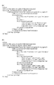
続いて、図10は、撮像光学系2の光路にIRCF4を挿入するか否かを撮像装置1000に自動で制御させる処理であるオートデイナイト処理を説明するためのフローチャートである。なお、この処理は、CPU26により実行される。
Next, FIG. 10 is a flowchart for explaining an automatic day / night process which is a process for automatically causing the
ステップS1001では、CPU26は、撮像光学系2の光路にIRCF4を挿入するか否かの判定に用いられる輝度閾値をEEPROM28から読み出す。そして、CPU26は、読み出した輝度閾値を、撮像光学系2の光路にIRCF4を挿入するか否かの判定に用いられる輝度閾値として、判定回路20に設定する。
In step S <b> 1001, the
ステップS1002では、CPU26は、撮像光学系2の光路にIRCF4を挿入するか否かの判定に用いられる遅延時間をEEPROM28から読み出す。そして、CPU26は、読み出した遅延時間を、撮像光学系2の光路にIRCF4を挿入するか否かの判定に用いられる遅延時間として、計時回路22に設定する。なお、この遅延時間は、図10では「応答性時間閾値」として示している。
In step S <b> 1002, the
ステップS1003では、CPU26は、判定回路20に指示し、撮像装置1000の被写体の現在の輝度値を輝度測定回路18から取得させる。
In step S <b> 1003, the
ステップS1004では、CPU26は、判定回路20に指示し、ステップS1001にて設定された輝度閾値とステップS1003で取得させた輝度値とを比較させる。なお、図10におけるステップS1004では、ステップS1003で取得させた輝度値を「推定輝度値」として示している。
In step S1004, the
ステップS1005では、CPU26は、ステップS1004の比較の結果、ステップS1003で取得させた輝度値がステップS1001にて設定された輝度閾値以上であるか否かを判定する。
In step S1005, the
そして、CPU26は、ステップS1003で取得させた輝度値がステップS1001にて設定された輝度閾値以上であると判定した場合には、ステップS1007に処理を進める。一方、CPU26は、ステップS1003で取得させた輝度値がステップS1001にて設定された輝度閾値以上ではないと判定した場合には、ステップS1004に処理を戻す。
If the
ステップS1006では、CPU26は、計時回路22に指示し、計時を停止させる。
In step S1006, the
ステップS1007では、CPU26は、計時回路22に指示し、計時を開始させる。
In step S1007, the
ステップS1008及びS1009は、ステップS1004及びS1005と同様であるので、その説明を省略する。 Since steps S1008 and S1009 are the same as steps S1004 and S1005, description thereof is omitted.
ステップS1010では、CPU26は、ステップS1007で計時を開始してからステップS1002で設定された遅延時間が経過した旨の通知を計時回路22から受けたか否かを判定する。なお、図10におけるステップS1010では、この遅延時間を「応答性時間経過」として示している。
In step S1010, the
そして、CPU26は、ステップS1007で計時を開始してからステップS1002で設定された遅延時間が経過した旨の通知を計時回路22から受けたと判定した場合には、ステップS1011に処理を進める。
If the
一方、CPU26は、CPU26は、ステップS1007で計時を開始してからステップS1002で設定された遅延時間が経過した旨の通知を計時回路22から受けていないと判定した場合には、ステップS1011に処理を進める。
On the other hand, if the
ステップS1011では、CPU26は、IRCF駆動回路24に指示し、撮像光学系2の光路にIRCF4を挿入させる。これにより、撮像装置1000は、可視光撮像を行うことになる。
In step S <b> 1011, the
以上のように、本実施例では、次のような場合を想定している。即ち、値がToOnのBoundaryTypeフィールドに対応するBoundaryOffsetフィールドの値が、値がToOffのBoundaryTypeフィールドのBoundaryOffsetフィールドの値よりも小さい場合である。 As described above, this embodiment assumes the following case. That is, the value of the BoundaryOffset field corresponding to the BoundaryType field whose value is ToOn is smaller than the value of the BoundaryOffset field of the BoundaryType field whose value is ToOff.
このような場合でも、本実施例における撮像装置1000は、このBoundaryOffsetフィールドの値を、値がToOnのBoundaryTypeフィールドのBoundaryOffsetフィールドの値よりも小さくすることができる。
Even in such a case, the
この結果、被写体の輝度が低いにも関わらず、撮像光学系2の光路にIRCF4が挿入されてしまい、撮像画像の被写体が黒つぶれしてしまうことを防止することができる。なおかつ、被写体の輝度が高いにも関わらず、撮像光学系2の光路からIRCF4が抜き去られてしまい、撮像画像の被写体が白飛びしてしまうことを防止することができる。 As a result, it is possible to prevent the IRCF 4 from being inserted into the optical path of the imaging optical system 2 even when the luminance of the subject is low, and the subject of the captured image from being blacked out. In addition, it is possible to prevent the IRCF 4 from being extracted from the optical path of the imaging optical system 2 even if the luminance of the subject is high, and the subject of the captured image from being blown out.
又、値がToOffのBoundaryTypeフィールドのBoundaryOffsetフィールドの値を、値がToOnのBoundaryTypeフィールドのBoundaryOffsetフィールドの値より小さくすることは、Onvifで有効である。 It is also effective for Onvif to make the value of the BoundaryOffset field of the BoundaryType field whose value is ToOff smaller than the value of the BoundaryOffset field of the BoundaryType field whose value is ToOn.
なぜならば、ONVIFは、撮像光学系2の光路にIRCF4を挿入する場合及びこの光路から抜去する場合のそれぞれのBoundaryOffsetフィールドの値の範囲を、同一範囲(−1.0から+1.0)に制限している。 This is because ONVIF limits the range of values in the BoundaryOffset field when the IRCF 4 is inserted into and removed from the optical path of the imaging optical system 2 to the same range (-1.0 to +1.0). doing.
このため、撮像光学系2の光路からIRCF4を抜去する場合のBoundaryOffsetフィールドの値が、この光路にIRCF4を挿入する場合のBoundaryOffsetフィールドの値よりも大きくすることは、ONVIF規格では正しい。 Therefore, it is correct in the ONVIF standard that the value of the BoundaryOffset field when the IRCF4 is removed from the optical path of the imaging optical system 2 is larger than the value of the BoundaryOffset field when the IRCF4 is inserted into this optical path.
したがって、ONVIF規格に準拠したクライアント装置からこのような2つのBoundaryOffsetフィールドが記述されたSetImagingSettingsコマンドが送信されることは、頻繁に起こり得るからである。 Therefore, it is possible that a SetImagingSettings command in which such two BoundaryOffset fields are described from a client device compliant with the ONVIF standard is frequently transmitted.
なお、本実施例におけるCPU26は、ステップS907にて、ステップS903で読み出された値から0.1を引いた値を、撮像光学系2の光路からIRCF4を抜去するか否かの判定に用いられる輝度値として、EEPROM28に記憶させた。しかしながら、これに限られるものではない。
In step S907, the
例えば、CPU26は、ステップS907にて、ステップS904で読み出された値に0.1を加えた値を、撮像光学系2の光路にIRCF4を挿入するか否かの判定に用いられる輝度値として、EEPROM28に記憶させても良い。さらに、CPU26は、ステップS907にて、ステップS904で読み出された値を、撮像光学系2の光路からIRCF4を抜去するか否かの判定に用いられる輝度値として、EEPROM28に記憶させても良い。
For example, in step S907, the
また、ステップS907にて、ステップS903で読み出された値から差し引かれる値(ステップS904で読み出された値に加えられる値)を「0.1」としているが、これに限られるものではない。 In step S907, the value subtracted from the value read in step S903 (the value added to the value read in step S904) is set to “0.1”, but is not limited thereto. .
例えば、CPU26は、ユーザにより操作されるクライアント装置2000から任意の値をI/F14経由で受信し、受信した値を、ステップS903で読み出された値から差し引かれる値(ステップS904で読み出された値に加えられる値)に設定しても良い。
For example, the
また、本実施例では、図10を用い、撮像光学系2の光路にIRCF4を挿入するか否か撮像装置1000に自動で制御させる処理を説明した。ここで、この光路からIRCF4を抜去するか否かを撮像装置1000に自動で制御させる処理についても、以下に説明する。
In the present embodiment, the process of automatically controlling the
ステップS1001では、CPU26は、撮像光学系2の光路からIRCF4を抜去するか否かの判定に用いられる輝度閾値をEEPROM28から読み出す。そして、CPU26は、読み出した輝度閾値を、撮像光学系2の光路からIRCF4を抜去するか否かの判定に用いられる輝度閾値として、判定回路20に設定する。
In step S <b> 1001, the
ステップS1002では、CPU26は、撮像光学系2の光路からIRCF4を抜去するか否かの判定に用いられる遅延時間をEEPROM28から読み出す。そして、CPU26は、読み出した遅延時間を、撮像光学系2の光路からIRCF4を抜去するか否かの判定に用いられる遅延時間として、計時回路22に設定する。
In step S <b> 1002, the
ステップS1003及びS1004は、上述のステップS1003及びS1004と同様であるので、その説明を省略する。 Since steps S1003 and S1004 are the same as steps S1003 and S1004 described above, description thereof is omitted.
ステップS1005では、CPU26は、ステップS1004の比較の結果、ステップS1003で取得させた輝度値がステップS1001にて設定された輝度閾値以下であるか否かを判定する。
In step S1005, the
そして、CPU26は、ステップS1003で取得させた輝度値がステップS1001にて設定された輝度閾値以下であると判定した場合には、ステップS1007に処理を進める。一方、CPU26は、ステップS1003で取得させた輝度値がステップS1001にて設定された輝度閾値以下ではないと判定した場合には、ステップS1004に処理を戻す。
If the
ステップS1006乃至S1010は、上述のステップS1006乃至S1010と同様であるので、その説明を省略する。 Since steps S1006 to S1010 are the same as steps S1006 to S1010 described above, description thereof will be omitted.
ステップS1011では、CPU26は、IRCF駆動回路24に指示し、撮像光学系2の光路からIRCF4を抜去させる。これにより、撮像装置1000は、赤外線撮像を行うことになる。
In step S <b> 1011, the
(実施例2)
続いて、図11を用い、本発明の実施例2について説明する。なお、上述の実施例と同一の構成要素については同一の符号を付し、その説明を省略することがある。
(Example 2)
Subsequently, Example 2 of the present invention will be described with reference to FIG. In addition, the same code | symbol is attached | subjected about the component same as the above-mentioned Example, and the description may be abbreviate | omitted.
ここで、上述の実施例1では、次のような場合を想定した。即ち、値がToOnのBoundaryTypeフィールドに対応するBoundaryOffsetフィールドの値が、値がToOffのBoundaryTypeフィールドに対応するBoundaryOffsetフィールドの値よりも低い場合である。 Here, in the above-described first embodiment, the following case is assumed. That is, the value of the BoundaryOffset field corresponding to the BoundaryType field whose value is ToOn is lower than the value of the BoundaryOffset field corresponding to the BoundaryType field whose value is ToOff.
そして、上述の実施例1では、このような場合でも、このBoundaryOffsetフィールドの値を、値がToOnのBoundaryTypeフィールドのBoundaryOffsetフィールドの値よりも小さくすることができる。 In the first embodiment described above, even in such a case, the value of the BoundaryOffset field can be made smaller than the value of the BoundaryOffset field of the BoundaryType field whose value is ToOn.
これに対し、実施例2における撮像装置1000は、このような場合に、それぞれのBoundaryOffsetフィールドの値が正しく設定されていないことを示す情報を、クライアント装置2000に送信する。
In contrast, in this case, the
これにより、クライアント装置2000を操作するユーザは、それぞれのBoundaryOffsetフィールドの値が正しく設定されていないことに気付くことができる。これから、このような点を考慮した実施例2を説明する。
As a result, the user who operates the
続いて、図11は、本実施例に係る撮像装置1000における、SetImagingSettings受信処理を説明するためのフローチャートである。
Next, FIG. 11 is a flowchart for explaining SetImagingSettings reception processing in the
なお、この処理は、CPU26により実行される。そして、CPU26は、クライアント装置2000からI/F14を介してSetImagingSettingsのコマンドを受信した場合に、この処理の実行を開始する。また、I/F14により受信されたSetImagingSettingsのコマンドは、EEPROM28に記憶されるものとする。
This process is executed by the
ステップS1101乃至S1106は、ステップS901乃至S906と同様であるのでその説明を省略する。 Since steps S1101 to S1106 are the same as steps S901 to S906, the description thereof is omitted.
ステップS1107では、CPU26は、I/F14に指示し、I/F14で受信されたSetImagingSettingsのコマンドが異常であることを示すSetImagingSettingsのレスポンスを、クライアント装置2000に送信させる。
In step S <b> 1107, the
なお、本実施例におけるI/F14は、I/F14で受信されたSetImagingSettingsコマンドが異常であることを示す情報を送信する送信部に相当する。 Note that the I / F 14 in this embodiment corresponds to a transmission unit that transmits information indicating that the SetImagingSettings command received by the I / F 14 is abnormal.
ステップS1108では、CPU26は、I/F14に指示し、I/F14で受信されたSetImagingSettingsのコマンドが正常であることを示すSetImagingSettingsのレスポンスを、クライアント装置2000に送信させる。
In step S <b> 1108, the
以上のように、本実施例では、次のような場合を想定している。即ち、値がToOnのBoundaryTypeフィールドに対応するBoundaryOffsetフィールドの値が、値がToOffのBoundaryTypeフィールドに対応するBounaryOffsetフィールドの値よりも小さい場合である。 As described above, this embodiment assumes the following case. That is, the value of the BoundaryOffset field corresponding to the BoundaryType field whose value is ToOn is smaller than the value of the BoundaryOffset field corresponding to the BoundaryType field whose value is ToOff.
このような場合でも、本実施例における撮像装置1000は、それぞれのBoundaryOffsetフィールドの値が正しく設定されていないことを示す情報を、クライアント装置2000に通知することができる。これにより、クライアント装置2000を操作するユーザは、それぞれのBounaryOffsetフィールドの値が正しく設定されていないことに気付くことができる。
Even in such a case, the
この結果、被写体の輝度が低いにも関わらず、撮像光学系2の光路にIRCF4が挿入されてしまうこと、及び、被写体の輝度が高いにも関わらず、撮像光学系2の光路からIRCF4が抜去されてしまうことを防止することができる。 As a result, the IRCF 4 is inserted into the optical path of the imaging optical system 2 even though the luminance of the subject is low, and the IRCF 4 is removed from the optical path of the imaging optical system 2 even though the luminance of the subject is high. Can be prevented.
(実施例3)
続いて、図12乃至14を用い、本発明の実施例3について説明する。なお、上述の実施例と同一の構成要素については同一の符号を付し、その説明を省略することがある。
(Example 3)
Subsequently, Embodiment 3 of the present invention will be described with reference to FIGS. In addition, the same code | symbol is attached | subjected about the component same as the above-mentioned Example, and the description may be abbreviate | omitted.
ここで、上述の実施例2では、次のような場合を想定した。即ち、値がToOnのBoundaryTypeフィールドに対応するBoundaryOffsetフィールドの値が、値がToOffのBoundaryTypeフィールドに対応するBoundaryOffsetフィールドの値よりも低い場合である。 Here, in the above-described second embodiment, the following case is assumed. That is, the value of the BoundaryOffset field corresponding to the BoundaryType field whose value is ToOn is lower than the value of the BoundaryOffset field corresponding to the BoundaryType field whose value is ToOff.
そして、上述の実施例2における撮像装置1000は、このような場合に、それぞれのBoundaryOffsetフィールドの値が正しく設定されていないことを示す情報を、クライアント装置2000に送信する。
In such a case, the
これに対し、実施例3におけるクライアント装置2000は、このような場合に、クライアント装置2000によってそれぞれのBoundaryOffsetフィールドの値が設定される際に、この値が正しく設定されていないことをユーザに通知する。
On the other hand, the
これにより、クライアント装置2000を操作するユーザは、それぞれのBoundaryOffsetフィールドの値が正しく設定されていないSetImagingSettingsコマンドの送信前に、この正しく設定されていないことに気付くことができる。これから、このような点を考慮した実施例3を説明する。
As a result, the user who operates the
続いて、図12は、本実施例に係るクライアント装置2000における、IrCutFilterAutoAdjustment設定画面の一例を示す図である。なお、この画面は、表示部422に表示される。
Next, FIG. 12 is a diagram illustrating an example of an IrCutFilterAutoAdjustment setting screen in the
図12(a)及び(b)におけるIRCFタイプ選択ペイン301は、Common選択チェックボックス303、ToOn選択チェックボックス305、ToOff選択チェックボックス307、及びBoundaryOffset設定数値ボックス309を含む。
The IRCF
また、IRCFタイプ選択ペイン301は、遅延時間設定数値ボックス311を含む。そして、IRCF設定ペイン315には、第一輝度閾値設定スケール317、第二輝度閾値設定スケール319、第一遅延時間設定スケール321、及び第二遅延時間設定スケール323が設けられている。さらに、図12に示す設定画面には、設定ボタン325及びキャンセルボタン327が設けられている。
The IRCF
ここで、IRCF設定ペイン315において、縦軸は、輝度値を示し、横軸は、遅延時間を示す。特に、IRCF設定ペイン315において、横軸上(Time軸上)は、輝度値0(零)を示し、上方の限界(上端)は、正規化された輝度値1.0を示す。また、下方の限界(下端)は、正規化された輝度値−1.0を示す。そして、IRCF設定ペイン315において、左の限界(左端)は、遅延時間0(零)を示すようになっている。
Here, in the
続いて、図12(a)は、撮像光学系2の光路にIRCF4を挿入する場合及び撮像光学系2の光路からIRCF4を抜去する場合のそれぞれについて輝度閾値や遅延時間を共通で設定する際における、設定画面の一例である。 Subsequently, FIG. 12A illustrates a case where the luminance threshold value and the delay time are set in common for the case where the IRCF 4 is inserted into the optical path of the imaging optical system 2 and the case where the IRCF 4 is removed from the optical path of the imaging optical system 2. It is an example of a setting screen.
即ち、図12(a)の画面は、値がCommonのBoundaryTypeフィールドが記述されたSetImagingSettingsコマンドを撮像装置1000に送信する場合に使用される設定画面である。
That is, the screen in FIG. 12A is a setting screen used when a SetImagingSettings command in which a BoundaryType field whose value is Common is described is transmitted to the
図12(a)におけるCommon選択チェックボックス303は、ユーザにより選択されている。これにより、撮像光学系2の光路にIRCF4を挿入する場合及びこの光路からIRCF4を抜去する場合のそれぞれについて共通の輝度閾値や遅延時間が撮像装置1000により使用されることになる。
A common
このため、第二輝度閾値設定スケール319及び第二遅延時間設定スケール323は、グレーアウトされている。つまり、第二輝度閾値設定スケール319及び第二遅延時間設定スケール323は、操作不可能な状態となっている。
For this reason, the second luminance
ユーザは、第一輝度閾値設定スケール317を上下にスライドさせることにより、ユーザの所望のBoundaryOffsetの値を設定する。そして、ユーザにより第一輝度閾値設定スケール317が操作されると、BoundaryOffset設定数値ボックス309におけるCommon相当部の値がこの操作に連動して変化する。
The user slides the first brightness
一方、ユーザは、BoundaryOffset設定数値ボックス309におけるCommon相当部に値を直接入力することもできる。そして、ユーザによりこのCommon相当部に値が入力されると、第一輝度閾値設定スケール317は、入力された値に応じて上下に移動する。
On the other hand, the user can also directly input a value in the Common equivalent part in the BoundaryOffset setting
このように、ユーザは、BoundaryOffsetの値を第一輝度閾値設定スケール317の位置により、大まかに把握することができる。更に、この位置とBoundaryOffset設定数値ボックス309におけるCommon相当部の値とは、連動するので、ユーザは、このCommon相当部により、BounarOffsetの値を正確に把握することができる。
Thus, the user can roughly grasp the value of BoundaryOffset from the position of the first luminance
なお、第一輝度閾値設定スケール317がTime軸上に配置された状態で、設定ボタン325が押下されると、クライアント装置2000は、BoundaryOffsetフィールドが省略されたSetImagingSettingsコマンドを送信する。
When the
同様に、BoundaryOffset設定数値ボックス309のCommon相当部に0(零)が入力された状態で、設定ボタン325が押下されても、クライアント装置2000は、この省略されたSetImagingSettingsコマンドを送信する。
Similarly, even if the
なお、本実施例では、ユーザは、第一輝度閾値設定スケール317をTime軸上に配置することや、このCommon相当部に0を入力することで、BoundaryOffsetフィールドの省略を指示することができるが、これに限られるものではない。
In this embodiment, the user can instruct the omission of the BoundaryOffset field by placing the first luminance
例えば、SetImagingSettingsコマンドにおけるBoundaryOffsetフィールドの省略を指示するためのGUIコンポーネントを、別途、表示部422に表示させるように構成しても良い。
For example, a GUI component for instructing to omit the BoundaryOffset field in the SetImagingSettings command may be separately displayed on the
具体的には、このようなGUIコンポーネントとしてBoundaryOffsetフィールド省略用チェックボックスを図12の画面に配置する。そして、ユーザによりこのチェックボックスが選択された場合に、SetImagingSettingsコマンドのBoundaryOffsetフィールドが省略されるように構成しても良い。 Specifically, a BoundaryOffset field omission check box is arranged on the screen of FIG. 12 as such a GUI component. Then, when this check box is selected by the user, the BoundaryOffset field of the SetImagingSettings command may be omitted.
また、ユーザは、第一遅延時間設定スケール321を左右にスライドさせることにより、ユーザの所望するResponseTimeの値を設定する。そして、ユーザにより第一遅延時間設定スケール321が操作されると、遅延時間設定数値ボックス311におけるCommon相当部の時間表示がこの操作に連動して変化する。
Also, the user sets the value of ResponseTime desired by the user by sliding the first delay
一方、ユーザは、遅延時間設定数値ボックス311におけるCommon相当部に時間を直接入力することもできる。そして、ユーザによりこのCommon相当部に時間が入力されると、第一遅延時間設定スケール321は、入力された時間に応じて左右に移動する。
On the other hand, the user can also directly input the time into the Common equivalent part in the delay time setting
なお、第一遅延時間設定スケール321がIRCF設定ペイン315の左端に配置された状態で、設定ボタン325が押下された場合を想定する。このような場合、クライアント装置2000は、ResponseTimeフィールドが省略されたSetImagingSettingsコマンドを送信する。
It is assumed that the
同様に、遅延時間設定数値ボックス311におけるCommon相当部の全ての数値ボックスに0(零)が入力された状態で、設定ボタン325が押下された場合を想定する。このような場合も、クライアント装置2000は、ResponseTimeフィールドが省略されたSetImagingSettingsコマンドを想定する。
Similarly, it is assumed that the
なお、本実施例では、第一遅延時間設定スケール321をIRCF設定ペイン315の左端に配置することや、遅延時間設定数値ボックス311のCommon相当部に0を入力することで、ResponseTimeフィールドの省略を指示することができる。しかしながら、これに限られるものではない。
In this embodiment, the response time field is omitted by placing the first delay
例えば、SetImagingSettingsコマンドにおけるResponseTimeフィールドの省略を指示するためのGUIコンポーネントを、別途、表示部422に表示させるように構成しても良い。
For example, a GUI component for instructing to omit the ResponseTime field in the SetImagingSettings command may be separately displayed on the
具体的には、このようなGUIコンポーネントとしてResponseTimeフィールド省略用チェックボックスを図12の画面に配置する。そして、ユーザによりこのチェックボックスが選択された場合に、SetImagingSettingsコマンドのResponeTimeフィールドが省略されるように構成しても良い。 Specifically, a ResponseTime field omission check box is arranged on the screen of FIG. 12 as such a GUI component. Then, when this check box is selected by the user, the ResponseTime field of the SetImagingSettings command may be omitted.
続いて、図12(b)は、撮像光学系2の光路にIRCF4を挿入する場合及び撮像光学系2の光路からIRCF4を抜去する場合のそれぞれについて輝度閾値や遅延時間を別々に設定する際における、設定画面の一例である。 Subsequently, FIG. 12B shows a case in which the brightness threshold and the delay time are separately set for each of the case where the IRCF 4 is inserted into the optical path of the imaging optical system 2 and the case where the IRCF 4 is removed from the optical path of the imaging optical system 2. It is an example of a setting screen.
即ち、図12(b)の画面は、それぞれ値がToOn及びToOffの2つのBoundaryTypeフィールドが記述されたSetImagingSettingsコマンドを撮像装置1000に送信する場合に使用される設定画面である。
That is, the screen of FIG. 12B is a setting screen used when transmitting a SetImagingSettings command in which two BoundaryType fields whose values are ToOn and ToOff are described to the
図12(b)におけるToOn選択チェックボックス305及びToOff選択チェックボックス307のそれぞれは、ユーザにより選択されている。これにより、撮像光学系2の光路にIRCF4を挿入する場合及びこの光路からIRCF4を抜去する場合のそれぞれについて輝度閾値や遅延時間を別々に設定することになる。
Each of the ToOn
このため、ユーザによりToOn選択チェックボックス305が選択されているので、第一輝度閾値設定スケール317、及び第一遅延時間設定スケール321のそれぞれが有効(操作可能な状態)となっている。また、ユーザによりToOff選択チェックボックス307が選択されているので、第二輝度閾値設定スケール319、及び第二遅延時間設定スケール323のそれぞれが有効(操作可能な状態)となっている。
Therefore, since the ToOn
ここで、第一輝度閾値設定スケール317により設定される輝度閾値と第一遅延時間設定スケール321により設定される遅延時間とは、撮像光学系2の光路にIRCF4を挿入するか否かを判定するために用いられることになる。
Here, the luminance threshold set by the first luminance
また、第二輝度閾値設定スケール319で設定される輝度閾値と第二遅延時間設定スケール323で設定される遅延時間とは、撮像光学系2の光路からIRCF4を抜去するか否かを判定するために用いられることになる。
Further, the luminance threshold set by the second luminance
なお、図12(b)の画面では、ユーザによりToOn選択チェックボックス305のみが選択されている場合には、第一輝度閾値設定スケール317及び第一遅延時間設定スケール321が操作可能な状態となる。
In the screen of FIG. 12B, when only the ToOn
そして、この場合、第二輝度閾値設定スケール319及び第二遅延時間設定スケール323は、グレーアウトされる。つまり、第二輝度閾値設定スケール319及び第二遅延時間設定スケール323は、操作不可能な状態となる。
In this case, the second luminance
一方、図12の画面では、ユーザによりToOff選択チェックボックス307のみが選択されている場合には、第二輝度閾値設定スケール319及び第二遅延時間設定スケール323が操作可能な状態となる。
On the other hand, in the screen of FIG. 12, when only the ToOff
そして、この場合、第二輝度閾値設定スケール319及び第二遅延時間設定スケール323は、グレーアウトされる。つまり、第二輝度閾値設定スケール319及び第二遅延時間設定スケール323は、操作不可能な状態となる。
In this case, the second luminance
なお、本実施例における図12の画面では、Common選択チェックボックス303、ToOn選択チェックボックス305、及びToOff選択チェックボックス307の全てを同時に選択することはできない。
Note that the common
例えば、ユーザによりCommon選択チェックボックス303が選択されている場合には、ToOn選択チェックボックス305及びToOff選択チェックボックス307は、操作不可能な状態となる。
For example, when the common
また、ToOn選択チェックボックス305及びToOff選択チェックボックス307のいずれか一方又は両方がユーザにより選択されている場合には、Common選択チェックボックス303は、操作不可能な状態となる。
When either or both of the ToOn
また、本実施例におけるクライアント装置2000は、図12の設定画面を表示部422に表示させる前に、GetImagingSettingsコマンドを撮像装置1000に送信しても良い。そして、クライアント装置2000は、撮像装置1000から送信されるGetImaginsSettingsレスポンスに応じ、表示部422に表示された図12の設定画面を更新しても良い。
In addition, the
ここで、このレスポンスは、IrCutFilterAutoAdjustmentフィールドを含む。このフィールドは、撮像装置1000の現在の、BoundaryTypeフィールドの値、BoundaryOffsetフィールドの値、及びResponseTimeフィールドの値が記述されている。
Here, this response includes an IrCutFilterAutoAdjustment field. In this field, the current value of the BoundaryType field, the value of the BoundaryOffset field, and the value of the ResponseTime field of the
例えば、クライアント装置2000は、撮像装置1000から受信したGetImagingSettingsレスポンスのBoundaryTypeフィールドの値がCommonのみである場合には、Common選択チェックボックス303を選択状態にする。
For example, when the value of the BoundaryType field of the GetImagingSettings response received from the
さらに、クライアント装置2000は、この場合に、このレスポンスに含まれるBoundaryOffsetフィールドの値を、BoundaryOffset設定数値ボックス309におけるCommon相当部に表示させる。
Further, in this case, the
なおかつ、クライアント装置2000は、この場合に、このレスポンスに含まれるResponseTimeフィールドの値を、遅延時間設定数値ボックス311におけるCommon相当部に表示させる。
Further, in this case, the
又、クライアント装置2000は、撮像装置1000から受信したGetImagingSettingsレスポンスのBoundaryTypeフィールドの値がToOn及びToOffのみである場合に、ToOn選択チェックボックス305を選択状態にする。更に、クライアント装置2000は、この場合には、ToOff選択チェックボックス307を選択状態にする。
In addition, the
また、クライアント装置2000は、この場合に、このレスポンスにおける値がToOnのBoundaryTypeフィールドに対応するBoundaryOffsetフィールドの値を、図12の画面に表示させる。より詳細には、クライアント装置2000は、この値を、BoundaryOffset設定数値ボックス309のToOn相当部に表示させる。
In this case, the
つぎに、クライアント装置2000は、この場合に、このレスポンスにおける値がToOffのBoundaryTypeフィールドに対応するBoundaryOffsetフィールドの値を、図12の画面に表示させる。より詳細には、クライアント装置2000は、この値を、BoundaryOffset設定数値ボックス309のToOff相当部に表示させる。
Next, in this case, the
そして、クライアント装置2000は、この場合に、このレスポンスにおける値がToOnのBoundaryTypeフィールドに対応するResponseTimeフィールドの値を、遅延時間設定数値ボックス311のToOn相当部に表示させる。
In this case, the
さらに、クライアント装置2000は、この場合に、このレスポンスにおける値がToOffのBoundaryTypeフィールドに対応するBoundaryOffsetフィールドの値を、遅延時間設定数値ボックス311のToOff相当部に表示させる。
Further, in this case, the
なお、クライアント装置2000は、ユーザによりキャンセルボタン327が押下されると、図12の画面の表示を終了する。
Note that when the user presses the cancel
また、本実施例におけるクライアント装置2000は、図12の設定画面を表示部422に表示させる前に、GetOptionsコマンドを撮像装置1000に送信しても良い。そして、クライアント装置2000は、撮像装置1000から送信されるGetOptionsレスポンスに応じ、表示部422に表示された図12の設定画面を更新しても良い。
Further, the
ここで、このレスポンスは、IrCutFilterAutoAdjustmetOptionsフィールドを含む。このフィールドは、撮像装置1000が受け付けることができるBoundaryTypeフィールドの値などが記述されている。
Here, this response includes an IrCutFilterAutoAdjustmetOptions field. In this field, the value of the BoundaryType field that can be received by the
例えば、クライアント装置2000は、撮像装置1000から受信したGetOptinsレスポンスのModeフィールドの値がCommonのみである場合には、図12(a)に示すように、Common選択チェックボックス303を選択状態にする。
For example, when the value of the Mode field of the GetOptins response received from the
また、クライアント装置2000は、撮像装置1000から受信したGetOptionsレスポンスのModeフィールドの値がToOn及びToOffのみである場合には、図12(b)に示すように、ToOn選択チェックボックス305を選択状態にする。更に、この場合に、クライアント装置2000は、ToOff選択チェックボックス307を選択状態にする。
Further, when the value of the Mode field of the GetOptions response received from the
ここで、図12(b)の設定画面において、BoundaryOffset設定数値ボックス309のToOn相当部の値は、0.16に設定されている。一方、この設定画面において、BoundaryOffset設定数値ボックス309のToOff相当部の値は、0.25に設定されている。
Here, in the setting screen of FIG. 12B, the value of the ToOn equivalent part of the BoundaryOffset setting
これでは、被写体の輝度が低い場合に、撮像光学系2の光路にIRCF4を挿入し、被写体の輝度が高い場合に、撮像光学系2の光路からIRCF4を抜去することになりかねず、正しいBoundaryOffsetの設定とは言い難い。 In this case, when the luminance of the subject is low, the IRCF 4 is inserted into the optical path of the imaging optical system 2, and when the luminance of the subject is high, the IRCF 4 may be removed from the optical path of the imaging optical system 2, and the correct BoundaryOffset is obtained. It is hard to say that the setting.
このため、クライアント装置2000は、ユーザにより設定ボタン325が押下さると、BoundaryOffsetの設定エラーである旨を、ポップアップダイアログ等を表示することにより、ユーザに知らせる。
For this reason, when the
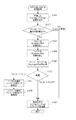
続いて、図13及び14は、本実施例に係るクライアント装置2000における、SetImagingSettings送信処理を説明するためのフローチャートである。
13 and 14 are flowcharts for explaining SetImagingSettings transmission processing in the
なお、この処理は、CPU426により実行される。そして、CPU426は、設定ボタン325が押下されたか否かを判定し、設定ボタン325が押下されたと判定した場合には、本処理を開始し、設定ボタン325が押下されていないと判定した場合には、本処理を開始しない。
This process is executed by the
ステップS1201では、CPU426は、SetImagingSettingsコマンドを生成し、生成したSetImagingSettingsコマンドをメモリ428に記憶させる。この記憶させたSetImagingSettingsコマンドにおけるIrCutFilterフィールドの値は、AUTOである。
In step S1201, the
これにより、図8(a)又は図8(b)に示すように、この記憶させたSetImagingSettingsコマンドの<IrCutFilter>タグには、AUTOが対応付けられている。 Thereby, as shown in FIG. 8A or FIG. 8B, AUTO is associated with the <IrCutFilter> tag of the stored SetImagingSettings command.
ステップS1202では、CPU426は、Common選択チェックボックス303が選択されているのか、それともToOn選択チェックボックス305及びToOff選択チェックボックス307が選択されているのか、を判定する。
In step S1202, the
そして、CPU426は、Common選択チェックボックス303が選択されていると判定した場合には、ステップS1203に処理を進める。一方、CPU426は、ToOn選択チェックボックス305及びToOff選択チェックボックス307が選択されていると判定した場合には、ステップS1301に処理を進める。
If the
ステップS1203では、CPU426は、ステップS1201で記憶させたコマンドに、値がCommonのBoundaryTypeフィールドを追加する。
In step S1203, the
これにより、図8(a)に示すように、この記憶させたコマンドには、<IrCutFilterAutoAdjustment>タグが記述される。さらに、このコマンドには、<BoundaryType>タグが、この<IrCutFilterAutoAdjustment>タグに対応付けられ且つ記述される。 Thereby, as shown in FIG. 8A, the <IrCutFilterAutoAdjustment> tag is described in the stored command. Further, in this command, a <BoundaryType> tag is associated with and described in the <IrCutFilterAutoAdjustment> tag.
その上、このコマンドには、Commonが、この<BoundaryType>タグに対応付けられ且つ記述される。 In addition, in this command, Common is associated with and described in this <BoundaryType> tag.
ステップS1204では、CPU426は、BoundaryOffset設定数値ボックス309におけるCommon相当部に値が設定されているか否かを判定する。そして、CPU426は、BoundaryOffset設定数値ボックス309におけるCommon相当部に値が設定されていると判定した場合には、ステップS1205に処理を進める。
In step S1204, the
一方、CPU426は、BoundaryOffset設定数値ボックス309におけるCommon相当部に値が設定されていないと判定した場合には、ステップS1206に処理を進める。
On the other hand, if the
ステップS1205では、CPU426は、ステップS1201で記憶させたコマンドに、BoundaryOffsetフィールドを追加する。このBoundaryOffsetフィールドの値は、BoundaryOffset設定数値ボックス309におけるCommon相当部に設定されている値である。
In step S1205, the
これで、図8(a)に示すように、この記憶させたコマンドには、<BoundaryOffset>タグが、このコマンドの<IrCutFilterAutoAdjustment>タグに対応付けられ、且つ記述される。さらに、このコマンドには、0.52がこの<BoundaryOffset>タグに対応付けられ且つ記述される。 Now, as shown in FIG. 8A, in this stored command, the <BoundaryOffset> tag is associated with and described in the <IrCutFilterAutoAdjustment> tag of this command. Further, in this command, 0.52 is associated with and described in the <BoundaryOffset> tag.
ステップS1206では、CPU426は、遅延時間設定数値ボックス311におけるCommon相当部に値が設定されているか否かを判定する。そして、CPU426は、遅延時間設定数値ボックス311におけるCommon相当部に値が設定されていると判定した場合には、ステップS1207に処理を進める。
In step S <b> 1206, the
一方、CPU426は、遅延時間設定数値ボックス311におけるCommon相当部に値が設定されていないと判定した場合には、ステップS1208に処理を進める。
On the other hand, if the
ステップS1207では、CPU426は、ステップS1201で記憶させたコマンドに、ResponseTimeフィールドを追加する。このResponseTimeフィールドの値は、遅延時間設定数値ボックス311におけるCommon相当部に設定されている値である。
In step S1207, the
これで、例えば、図8(a)に示すように、この記憶させたコマンドには、<ResponseTime>タグが、このコマンドの<IrCutFilterAutoAdjustment>タグに対応付けられ、且つ記述される。さらに、このコマンドには、PT1M15Sがこの<ResponseTime>タグに対応付けられ、且つ記述される。 Thus, for example, as shown in FIG. 8A, in the stored command, the <ResponseTime> tag is associated with and described in the <IrCutFilterAutoAdjustment> tag of this command. Further, in this command, PT1M15S is associated with and described in the <ResponseTime> tag.
ステップS1208では、CPU426は、I/F414に指示し、ステップS120
1で記憶させたコマンドを撮像装置1000に送信させる。
In step S1208, the
The command stored in 1 is transmitted to the
続いて、図14におけるステップS1301では、CPU426は、BoundaryOffset設定数値ボックス309におけるToOn相当部に値が設定されているか否かを判定する。
Subsequently, in step S1301 in FIG. 14, the
そして、CPU426は、BoundaryOffset設定数値ボックス309におけるToOn相当部に値が設定されていると判定した場合には、この設定されている値を取得し、ステップS1302に処理を進める。一方、CPU426は、BoundaryOffset設定数値ボックス309におけるToOn相当部に値が設定されていないと判定した場合には、図13及び図14に示す処理を終了する。
If the
ステップS1302では、CPU426は、BoundaryOffset設定数値ボックス309におけるToOff相当部に値が設定されているか否かを判定する。
In step S1302, the
そして、CPU426は、BoundaryOffset設定数値ボックス309におけるToOff相当部に値が設定されていると判定した場合には、この設定されている値を取得し、ステップS1303に処理を進める。一方、CPU426はBoundaryOffset設定数値ボックス309におけるToOff相当部に値が設定されていないと判定した場合には、図13及び図14に示す処理を終了する。
If the
ステップS1303では、CPU426は、ステップS1301で取得された値がステップS1302で取得された値よりも大きいか否かを判定する。
In step S1303, the
そして、CPU426は、ステップS1301で取得された値がステップS1302で取得された値よりも大きいと判定した場合には、ステップS1304に処理を進める。一方、CPU426は、ステップS1301で取得された値がステップS1302で取得された値よりも大きくないと判定した場合には、ステップS1313に処理を進める。
If the
なお、ステップS1303におけるCPU426は、ステップS1301で取得された値がステップS1302で取得された値よりも大きいか否かを判定する輝度値判定部に相当する。
Note that the
ステップS1304では、CPU426は、ステップS1201で記憶させたコマンドに、値がToOnのBoundaryTypeフィールド、及び値がToOffのBoundaryTypeフィールドを追加する。
In step S1304, the
これにより、図8(b)に示すように、この記憶させたコマンドには、2つの<IrCutFilterAutoAdjustment>タグが記述される。さらに、このコマンドには、<BoundaryType>タグが、この2つの<IrCutFilterAutoAdjustment>タグのうち1つ目の<IrCutFilterAutoAdjustment>タグに対応付けられ、且つ記述される。 Thereby, as shown in FIG. 8B, two <IrCutFilterAutoAdjustment> tags are described in the stored command. Further, in this command, a <BoundaryType> tag is associated with and described in the first <IrCutFilterAutoAdjustment> tag of the two <IrCutFilterAutoAdjustment> tags.
その上、このコマンドには、ToOnが、この<BoundaryType>タグに対応付けられ、且つ記述される。 In addition, in this command, ToOn is associated with and described in this <BoundaryType> tag.
また、このコマンドには、<BoundaryType>タグが、この2つの<IrCutFilterAutoAdjustment>タグのうち2つ目の<IrCutFilterAutoAdjustment>タグに対応付けられ、且つ記述される。そして、このコマンドには、ToOffが、この<BoundaryType>タグに対応付けられ、且つ記述される。 In this command, a <BoundaryType> tag is associated with and described in the second <IrCutFilterAutoAdjustment> tag of the two <IrCutFilterAutoAdjustment> tags. In this command, ToOff is associated with and described in the <BoundaryType> tag.
ステップS1305では、CPU426は、BoundaryOffset設定数値ボックス309におけるToOn相当部に値が設定されているか否かを判定する。そして、CPU426は、BoundaryOffset設定数値ボックス309におけるToOn相当部に値が設定されていると判定した場合には、ステップS1306に処理を進める。
In step S1305, the
一方、CPU426は、BoundaryOffset設定数値ボックス309におけるToOn相当部に値が設定されていないと判定した場合には、ステップS1307に処理を進める。
On the other hand, if the
ステップS1306では、CPU426は、ステップS1201で記憶させたコマンドに、BoundaryOffsetフィールドを追加する。また、このBoundaryOffsetフィールドの値は、BoundaryOffset設定数値ボックス309におけるToOn相当部に設定された値である。さらに、このBoundaryOffsetフィールドは、値がToOnのBoundarTypeフィールドに対応付けられる。
In step S1306, the
これにより、図8(b)に示すように、この記憶させたコマンドに、値が0.16の<BoundaryOffset>タグが、2つの<IrCutFilterAutoAdjustment>タグのうち1つ目のタグに対応付けられ、且つ記述される。 As a result, as shown in FIG. 8B, in this stored command, a <BoundaryOffset> tag having a value of 0.16 is associated with the first tag of the two <IrCutFilterAutoAdjustment> tags. And described.
ステップS1307では、CPU426は、BoundaryOffset設定数値ボックス309におけるToOff相当部に値が設定されているか否かを判定する。
In step S1307, the
そして、CPU426は、BoundaryOffset設定数値ボックス309におけるToOff相当部に値が設定されていると判定した場合には、ステップS1308に処理を進める。一方、CPU426は、BoundaryOffset設定数値ボックス309におけるToOff相当部に値が設定されていないと判定した場合には、ステップS1309に処理を進める。
If the
ステップS1308では、CPU426は、ステップS1201で記憶させたコマンドに、BoundaryOffsetフィールドを追加する。また、このBoundaryOffsetフィールドの値は、BoundaryOffset設定数値ボックス309におけるToOff相当部に設定された値である。
In step S1308, the
さらに、このBoundaryOffsetフィールドは、値がToOffのBoundarTypeフィールドに対応付けられる。 Further, this BoundaryOffset field is associated with a BoundaryType field whose value is ToOff.
これにより、例えば、この記憶させたコマンドに、値が−0.76の<BoundaryOffset>タグが、2つの<IrCutFilterAutoAdjustment>タグのうち2つ目のタグに対応付けられ、且つ記述される。 Thereby, for example, in this stored command, a <BoundaryOffset> tag having a value of −0.76 is associated with and described in the second tag of the two <IrCutFilterAutoAdjustment> tags.
ステップS1309では、CPU426は、遅延時間設定数値ボックス311におけるToOn相当部に値が設定されているか否かを判定する。そして、CPU426は、遅延時間設定数値ボックス311におけるToOn相当部に値が設定されていると判定した場合には、ステップS1310に処理を進める。
In step S1309, the
一方、CPU426は、遅延時間設定数値ボックス311におけるToOn相当部に値が設定されていないと判定した場合には、ステップS1311に処理を進める。
On the other hand, if the
ステップS1310では、CPU426は、ステップS1201で記憶させたコマンドに、ResponseTimeフィールドを追加する。また、このResponseTimeフィールドの値は、遅延時間設定数値ボックス311におけるToOn相当部に設定された値である。さらに、このResponseTimeフィールドは、値がToOnのBoundarTypeフィールドに対応付けられる。
In step S1310,
これにより、例えば、図8(b)に示すように、この記憶させたコマンドに、値がPT1M30Sの<ResponseTime>タグが、2つの<IrCutFilterAutoAdjustment>タグのうち1つ目のタグに対応付けられ、且つ記述される。 Thus, for example, as shown in FIG. 8B, in this stored command, the <ResponseTime> tag having the value PT1M30S is associated with the first tag of the two <IrCutFilterAutoAdjustment> tags. And described.
ステップS1311では、CPU426は、遅延時間設定数値ボックス311におけるToOff相当部に値が設定されているか否かを判定する。そして、CPU426は、遅延時間設定数値ボックス311におけるToOff相当部に値が設定されていると判定した場合には、ステップS1312に処理を進める。
In step S <b> 1311, the
一方、CPU426は、遅延時間設定数値ボックス311におけるToOff相当部に値が設定されていないと判定した場合には、ステップS1208に処理を進める。
On the other hand, if the
ステップS1312では、CPU426は、ステップS1201で記憶させたコマンドに、ResponseTimeフィールドを追加する。また、このResponseTimeフィールドの値は、遅延時間設定数値ボックス311におけるToOff相当部に設定された値である。さらに、このResponseTimeフィールドは、値がToOffのBoundarTypeフィールドに対応付けられる。
In step S1312, the
これにより、例えば、図8(b)に示すように、この記憶させたコマンドに、値がPT1M10Sの<ResponseTime>タグが、2つの<IrCutFilterAutoAdjustment>タグのうち2つ目のタグに対応付けられ、且つ記述される。 Thus, for example, as shown in FIG. 8B, in this stored command, the <ResponseTime> tag with the value PT1M10S is associated with the second tag of the two <IrCutFilterAutoAdjustment> tags, And described.
ステップS1313では、CPU426は、表示部422に指示し、エラーを示すメッセージ等の情報を表示させる。この情報は、例えば、次のようなことを示す。即ち、値がToOnのBoundaryTypeフィールドに対応するBoundaryOffsetフィールドの値が、値がToOffのBoundaryTypeフィールドに対応するBoundaryOffsetフィールドの値よりも低いことである。
In step S1313, the
ここで、本実施例におけるCPU426は、エラーを示す情報を表示部422に表示させる表示制御部に相当する。
Here, the
以上のように、本実施例では、次のような場合を想定した。即ち、値がToOnのBoundaryTypeフィールドに対応するBoundaryOffsetフィールドの値が、値がToOffのBoundaryTypeフィールドに対応するBoundaryOffsetフィールドの値よりも低い場合である。 As described above, in this embodiment, the following cases are assumed. That is, the value of the BoundaryOffset field corresponding to the BoundaryType field whose value is ToOn is lower than the value of the BoundaryOffset field corresponding to the BoundaryType field whose value is ToOff.
そして、本実施例におけるクライアント装置2000は、このような場合に、クライアント装置2000によってそれぞれのBoundaryOffsetフィールドの値が設定される際に、この値が正しく設定されていないことをユーザに通知することができる。
これにより、クライアント装置2000を操作するユーザは、それぞれのBoundaryOffsetフィールドの値が正しく設定されていないSetImagingSettingsコマンドの送信前に、この正しく設定されていないことに気付くことができる。
In such a case, the
As a result, the user who operates the
この結果、被写体の輝度が低いにも関わらず、撮像光学系2の光路にIRCF4が挿入されてしまうこと、及び、被写体の輝度が高いにも関わらず、撮像光学系2の光路からIRCF4が抜去されてしまうことを未然に防止することができる。 As a result, the IRCF 4 is inserted into the optical path of the imaging optical system 2 even though the luminance of the subject is low, and the IRCF 4 is removed from the optical path of the imaging optical system 2 even though the luminance of the subject is high. It can be prevented in advance.
なお、本実施例におけるIrCutFilterAutoAdjustment設定画面は、SetImagingSettingsコマンドに記述されるBoundaryOffsetフィールド等の値を入力させるためのユーザーインターフェース部に相当する。 Note that the IrCutFilterAutoAdjustment setting screen in the present embodiment corresponds to a user interface unit for inputting values such as the BoundaryOffset field described in the SetImagingSettings command.
(実施例4)
続いて、図15及び16を用い、本発明の実施例4について説明する。なお、上述の実施例と同一の構成要素については同一の符号を付し、その説明を省略することがある。
Example 4
Subsequently, Embodiment 4 of the present invention will be described with reference to FIGS. In addition, the same code | symbol is attached | subjected about the component same as the above-mentioned Example, and the description may be abbreviate | omitted.
ここで、上述の実施例3では、次のような場合を想定した。即ち、値がToOnのBoundaryTypeフィールドに対応するBoundaryOffsetフィールドの値が、値がToOffのBoundaryTypeフィールドに対応するBoundaryOffsetフィールドの値よりも低い場合である。 Here, in the above-described third embodiment, the following case is assumed. That is, the value of the BoundaryOffset field corresponding to the BoundaryType field whose value is ToOn is lower than the value of the BoundaryOffset field corresponding to the BoundaryType field whose value is ToOff.
そして、上述の実施例3におけるクライアント装置2000は、このような場合に、クライアント装置2000によってそれぞれのBoundaryOffsetフィールドの値が設定される際に、この値が正しく設定されていないことをユーザに通知する。
In such a case, the
これに対し、実施例4における撮像装置1000は、このような場合に、それぞれのBoundaryOffsetフィールドの値を、EEPROM28に記憶された変換テーブルを用いることにより変換する。
On the other hand, in such a case, the
これにより、撮像光学系2の光路にIRCF4を挿入するか否かの判定に用いられる輝度閾値を、撮像光学系2の光路からIRCF4を抜去するか否かの判定に用いられる輝度閾値よりも大きくすることができる。これから、このような点を考慮した実施例4を説明する。 Thereby, the luminance threshold value used for determining whether to insert IRCF 4 into the optical path of the imaging optical system 2 is larger than the luminance threshold value used for determining whether to remove IRCF 4 from the optical path of the imaging optical system 2. can do. The fourth embodiment in consideration of such points will now be described.
続いて、図15は、本実施例に係る、SetImaginsSettinsコマンドにおけるBoundaryOffsetフィールドの値と、被写体の輝度値とが対応付けられたテーブルである。 FIG. 15 is a table in which the value of the BoundaryOffset field in the SetImagesSettins command and the luminance value of the subject are associated with each other according to the present embodiment.
図15(a)は、SetImagingSettingsコマンドにおける値がToOnのBounaryTypeフィールドに対応付けられたBoundaryOffsetフィールドの値と、被写体の輝度値とが対応付けられたテーブル1401を示す。 FIG. 15A shows a table 1401 in which the value of the BoundaryOffset field associated with the BoundaryType field whose value in the SetImagingSettings command is ToOn is associated with the luminance value of the subject.
又、図15(b)は、SetImagingSettignsコマンドにおける値がToOffのBounaryTypeフィールドに対応付けられたBoundaryOffsetフィールドの値と、被写体の輝度値とが対応付けられたテーブル1402を示す。 FIG. 15B shows a table 1402 in which the value of the BoundaryOffset field associated with the BoundaryType field whose value in the SetImagingSettings command is ToOff is associated with the luminance value of the subject.
なお、これらのテーブルは、EEPROM28に記憶されるものとする。また、テーブル1401及び1402における被写体の輝度値は、輝度測定回路18から取得される輝度値である。
Note that these tables are stored in the
ToOn用のテーブル1401では、BoundaryOffsetの値「−1(−1.0)」には、被写体の輝度値「50」が対応付けられている。ここで、ToOn用のテーブル1401では、BoundaryOffsetの値が大きくなるに連れて、この値に対応付けられる被写体の輝度値も大きくなる。 In the ToOn table 1401, the value “−1 (−1.0)” of the Boundary Offset is associated with the luminance value “50” of the subject. Here, in the ToOn table 1401, as the value of BoundaryOffset increases, the luminance value of the subject associated with this value also increases.
そして、ToOn用のテーブル1401では、BoundaryOffsetの値「+1(+1.0)」には、被写体の輝度値「100」が対応付けられている。 In the ToOn table 1401, the luminance value “100” of the subject is associated with the value “+1 (+1.0)” of the BoundaryOffset.
又、ToOff用のテーブル1402では、BoundaryOffsetの値「−1(−1.0)」には、被写体の輝度値「20」が対応付けられている。ここで、テーブル1402では、BoundaryOffsetの値が大きくなるに連れて、この値に対応付けられる被写体の輝度値も大きくなる。 Further, in the ToOff table 1402, the BoundaryOffset value “−1 (−1.0)” is associated with the luminance value “20” of the subject. Here, in the table 1402, as the value of BoundaryOffset increases, the luminance value of the subject associated with this value also increases.
そして、ToOff用のテーブル1402では、BoundaryOffsetの値「+1(+1.0)」には、被写体の輝度値「40」が対応付けられている。 In the ToOff table 1402, the Boundary Offset value “+1 (+1.0)” is associated with the luminance value “40” of the subject.
このように、テーブル1401における被写体の輝度値の範囲(第1の範囲)の下限値は、テーブル1402における被写体の輝度値の範囲(第2の範囲)の上限値よりも大きい。 As described above, the lower limit value of the range of the luminance value of the subject (first range) in the table 1401 is larger than the upper limit value of the range of the luminance value of the subject (second range) in the table 1402.
続いて、図16は、本実施例に係る撮像装置1000における、SetImagingSettings受信処理を説明するためのフローチャートである。
Next, FIG. 16 is a flowchart for explaining SetImagingSettings reception processing in the
なお、この処理は、CPU26により実行される。そして、CPU26は、クライアント装置2000からI/F14を介してSetImagingSettingsのコマンドを受信した場合に、この処理の実行を開始する。また、I/F14により受信されたSetImagingSettingsのコマンドは、EEPROM28に記憶されるものとする。
This process is executed by the
ステップS1501乃至S1503は、ステップS901乃至903と同様であるので、その説明を省略する。 Since steps S1501 to S1503 are the same as steps S901 to S903, description thereof is omitted.
ステップS1504では、CPU26は、ステップS1503で読み出されたBoundaryOffsetの値に対応付けられた被写体の輝度値を、EEPROM28に記憶されたテーブル1401から読み出す。そして、CPU26は、読み出した輝度値を、撮像光学系2の光路にIRCF4を挿入するか否かを判定するために用いられる輝度閾値として、判定回路20に設定する。
In step S1504, the
なお、本実施例におけるCPU26は、I/F14で受信されたSetImagingSettingsコマンドに記述されたBoundaryOffsetの値を変換する変換部に相当する。
The
ステップS1505は、ステップS904と同様であるので、その説明を省略する。 Since step S1505 is the same as step S904, description thereof is omitted.
ステップS1506では、CPU26は、ステップS1505で読み出されたBoundaryOffsetの値に対応付けられた被写体の輝度値を、EEPROM28に記憶されたテーブル1402から読み出す。そして、CPU26は、読み出した輝度値を、撮像光学系2の光路からIRCF4を抜去するか否かを判定するために用いられる輝度閾値として、判定回路20に設定する。
In step S <b> 1506, the
ステップS1507は、ステップS1108と同様であるので、その説明を省略する。 Since step S1507 is the same as step S1108, description thereof is omitted.
以上のように、本実施例の撮像装置1000は、テーブル1401に基づき、値がToOnのBoundaryTypeに対応するBoundaryOffsetの値を、撮像光学系2の光路にIRCF4を挿入するか否かを判定するための輝度閾値に変換する。
As described above, the
更に、撮像装置1000は、テーブル1402に基づき、値がToOffのBoundaryTypeに対応するBoundaryOffsetの値を、撮像光学系2の光路からIRCF4を抜去するか否かを判定するための輝度閾値に変換する。
Furthermore, the
ここで、テーブル1401における被写体の輝度値の最低値(「50」)は、テーブル1402における被写体の輝度の最高値(「40」)よりも大きい。 Here, the lowest value (“50”) of the luminance value of the subject in the table 1401 is larger than the highest value (“40”) of the luminance of the subject in the table 1402.
これにより、次のような場合でも、撮像光学系2の光路にIRCF4を挿入するか否かを判定するための輝度閾値が、この光路からIRCF4を抜去するか否かを判定するための輝度閾値よりも小さくなってしまうことを防止することができる。 Thereby, even in the following cases, the luminance threshold for determining whether or not to insert the IRCF 4 into the optical path of the imaging optical system 2 is the luminance threshold for determining whether or not to remove the IRCF 4 from this optical path. Can be prevented from becoming smaller.
即ち、値がToOnのBoundaryTypeフィールドに対応するBoundaryOffsetフィールドの値が、値がToOffのBoundaryTypeフィールドに対応するBounaryOffsetフィールドの値よりも小さい場合である。 That is, the value of the BoundaryOffset field corresponding to the BoundaryType field whose value is ToOn is smaller than the value of the BoundaryOffset field corresponding to the BoundaryType field whose value is ToOff.
この結果、クライアント装置2000によってそれぞれのBoundaryOffsetフィールドの値がどのように設定されたとしても、被写体の輝度が低いにも関わらず、撮像光学系2の光路にIRCF4が挿入されてしまうことを防止することができる。更に、被写体の輝度が高いにも関わらず、撮像光学系2の光路からIRCF4が抜去されてしまうことを防止することができる。
As a result, no matter how the values of the respective BoundaryOffset fields are set by the
なお、本実施例では、テーブル1401における被写体の輝度値の最低値は、テーブル1402における被写体の輝度値の最高値よりも大きくなるようにした。ここで、上述のような防止効果は小さくなってしまうが、次のような構成も考えられる。 In this embodiment, the minimum value of the luminance value of the subject in the table 1401 is set to be larger than the maximum value of the luminance value of the subject in the table 1402. Here, although the prevention effect as described above is reduced, the following configuration is also conceivable.
即ち、テーブル1402における被写体の輝度値の最高値を、テーブル1401における被写体の輝度値の指定値よりも僅かに大きくさせ、テーブル1401の被写体の輝度値の範囲とテーブル1402の被写体の輝度値の範囲とを一部重複させる構成である。 That is, the maximum value of the subject brightness value in the table 1402 is made slightly larger than the designated value of the subject brightness value in the table 1401, and the subject brightness value range in the table 1401 and the subject brightness value range in the table 1402 are set. Is partially overlapped.
(実施例5)
続いて、図17を用いて、本発明の実施例5について説明する。なお、上述の実施例と同一の構成要素については同一の符号を付し、その説明を省略することがある。
(Example 5)
Subsequently, Example 5 of the present invention will be described with reference to FIG. In addition, the same code | symbol is attached | subjected about the component same as the above-mentioned Example, and the description may be abbreviate | omitted.
ここで、上述の実施例4における撮像装置1000は、EEPROM28に記憶されたテーブルに基づき、それぞれのBoundaryOffsetフィールドの値を、判定回路20で用いられる輝度閾値に変換する。
Here, the
これにより、次のような場合でも、撮像光学系2の光路にIRCF4を挿入するか否かを判定するための輝度閾値が、この光路からIRCF4を抜去するか否かを判定するための輝度閾値よりも小さくなってしまうことを防止することができる。 Thereby, even in the following cases, the luminance threshold for determining whether or not to insert the IRCF 4 into the optical path of the imaging optical system 2 is the luminance threshold for determining whether or not to remove the IRCF 4 from this optical path. Can be prevented from becoming smaller.
即ち、値がToOnのBoundaryTypeフィールドに対応するBoundaryOffsetフィールドの値が、値がToOffのBoundaryTypeフィールドに対応するBoundaryOffsetフィールドの値よりも低い場合である。 That is, the value of the BoundaryOffset field corresponding to the BoundaryType field whose value is ToOn is lower than the value of the BoundaryOffset field corresponding to the BoundaryType field whose value is ToOff.
これに対し、実施例5における撮像装置1000は、このような場合に、それぞれのBoundaryOffsetフィールドの値を交換し、交換した値で判定回路20に輝度閾値を設定する。
On the other hand, in such a case, the
これにより、EEPROM28にテーブルを記憶させず、撮像光学系2の光路にIRCF4を挿入するか否かを判定するための輝度閾値が、この光路からIRCF4を抜去するか否かを判定するための輝度閾値よりも小さくなってしまうことを防止することができる。
As a result, the brightness threshold for determining whether to insert IRCF 4 into the optical path of the imaging optical system 2 without storing the table in the
続いて、図17は、本実施例に係る撮像装置1000における、SetImagingSettings受信処理を説明するためのフローチャートである。
Next, FIG. 17 is a flowchart for explaining SetImagingSettings reception processing in the
ステップS1601乃至S1606は、ステップS901乃至S906と同様であるので、その説明を省略する。 Steps S1601 to S1606 are the same as steps S901 to S906, and a description thereof will be omitted.
ステップS1607では、CPU26は、ステップS1603で読み出された値に対応する輝度閾値を、撮像光学系2の光路からIRCF4を抜去するか否かを判定するための輝度閾値として、EEPROM28に記憶させる。
In step S <b> 1607, the
ステップS1608では、CPU26は、ステップS1604で読み出された値に対応する輝度閾値を、撮像光学系2の光路にIRCF4を挿入するか否かを判定するための輝度閾値として、EEPROM28に記憶させる。
In step S1608, the
以上のように、本実施例では、次のような場合を想定している。即ち、値がToOnのBoundaryTypeフィールドに対応するBoundaryOffsetフィールドの値が、値がToOffのBoundaryTypeフィールドに対応するBounaryOffsetフィールドの値よりも小さい場合である。 As described above, this embodiment assumes the following case. That is, the value of the BoundaryOffset field corresponding to the BoundaryType field whose value is ToOn is smaller than the value of the BoundaryOffset field corresponding to the BoundaryType field whose value is ToOff.
そして、本実施例における撮像装置1000は、このような場合に、それぞれのBoundaryOffetフィールドの値を交換し、交換した値に基づき、判定回路20に輝度閾値を設定する。
In such a case, the
これにより、EEPROM28にテーブルを記憶させず、撮像光学系2の光路にIRCF4を挿入するか否かを判定するための輝度閾値が、この光路からIRCF4を抜去するか否かを判定するための輝度閾値よりも小さくなってしまうことを防止することができる。
As a result, the brightness threshold for determining whether to insert IRCF 4 into the optical path of the imaging optical system 2 without storing the table in the
なお、上述の実施例では、撮像光学系2の光路に挿脱される光学フィルタとして、IRCF4を用いたが、これに限られるものではない。例えば、このような光学フィルタとして、IRCF4の代わりに、撮像素子から出力される撮像画像の発色に影響を与えることなく、被写体からの光の光量を少なくするためのNDフィルタを用いても良い。 In the above-described embodiment, the IRCF 4 is used as the optical filter that is inserted into and removed from the optical path of the imaging optical system 2, but the present invention is not limited to this. For example, as such an optical filter, an ND filter for reducing the amount of light from the subject without affecting the color development of the captured image output from the image sensor may be used instead of the IRCF 4.
また、上述の実施例における、BoundaryOffsetフィールドは、例えば、赤外線遮断フィルタの有効(On)/無効(Off)の切り換えのための境界露光レベルを調整するためのパラメータであると言える。ここで、この有効とは、撮像光学系2の光路にIRCF4が挿入された状態であることを意味する。また、この無効とは、撮像光学系2の光路からIRCF4が抜去された状態であることを意味する。 In addition, the BoundaryOffset field in the above-described embodiment can be said to be a parameter for adjusting the boundary exposure level for switching between effective (On) and invalid (Off) of the infrared cut-off filter, for example. Here, this effective means that the IRCF 4 is inserted in the optical path of the imaging optical system 2. Further, this invalid means that the IRCF 4 is removed from the optical path of the imaging optical system 2.
そして、このBoundaryOffsetフィールドの値は、例えば、−1.0から+1.0に正規化された値であり、単位はない。さらに、BoundaryOffsetフィールドの値は、0が初期値であり、且つ、−1.0が最も暗く、+1.0が最も明るい。 The value of the BoundaryOffset field is a value normalized from −1.0 to +1.0, for example, and has no unit. Further, the value of the BoundaryOffset field is 0 as an initial value, -1.0 is the darkest, and +1.0 is the brightest.
また、上述の実施例におけるSetImagingSettingsコマンドには、値CommonのBoundaryTypeフィールドを記述することができる。ここで、このコマンドには、値がToOnのBoundaryTypeフィールド、及び値がToOffのBoundaryTypeフィールドが記述されていないものとする。 Further, the BoundaryType field of the value Common can be described in the SetImagingSettings command in the above-described embodiment. Here, it is assumed that the BoundaryType field whose value is ToOn and the BoundaryType field whose value is ToOff are not described in this command.
一方、上述の実施例におけるSetImagingsSettingsコマンドには、値がToOnのBoundaryTypeフィールド及び値がToOffのBoundaryTypeフィールドを記述することができる。ここで、このコマンドには、値がCommonのBoundaryTypeフィールドが記述されていないものとする。 On the other hand, in the SetImagingsSettings command in the above-described embodiment, a BoundaryType field whose value is ToOn and a BoundaryType field whose value is ToOff can be described. Here, it is assumed that the BoundaryType field whose value is Common is not described in this command.
したがって、SetImagingSettingsコマンドには、撮像光学系2の光路にIRCF4を挿入する場合及びこの光路からIRCF4を抜去する場合のそれぞれについて、BoundaryOffsetフィールドが別々に記述されることができる。さらに、このSetImagingSettingsコマンドには、このそれぞれについて、BoundaryOffsetフィールドが共通に記述されることができる。 Therefore, in the SetImagingSettings command, the BoundaryOffset field can be described separately for each of the case where the IRCF 4 is inserted into the optical path of the imaging optical system 2 and the case where the IRCF 4 is removed from the optical path. Further, the BoundaryOffset field can be commonly described for each of the SetImagingSettings commands.
(その他の実施例)
また、本発明は、以下の処理を実行することによっても実現される。即ち、上述した実施例の機能を実現するソフトウエア(プログラム)を、ネットワーク又は各種記憶媒体を介してシステム或いは装置に提供し、そのシステム或いは装置のコンピュータ(またはCPUやMPU等)がプログラムを読み出して実行する処理である。
(Other examples)
The present invention can also be realized by executing the following processing. That is, software (program) that realizes the functions of the above-described embodiments is provided to a system or apparatus via a network or various storage media, and the computer (or CPU, MPU, etc.) of the system or apparatus reads the program. To be executed.
以上、本発明の好ましい実施例について説明したが、本発明はこれらの実施例に限定されず、その要旨の範囲内で種々の変形及び変更が可能である。 As mentioned above, although the preferable Example of this invention was described, this invention is not limited to these Examples, A various deformation | transformation and change are possible within the range of the summary.
2 撮像光学系
4 IRCF
14 通信回路
24 IRCF駆動回路
26 CPU
1500 IPネットワーク網
2000 クライアント装置
2 Imaging optics 4 IRCF
14
1500
Claims (21)
撮像光学系と、
前記撮像光学系により結像された被写体の像を撮像する撮像手段と、
赤外線を遮断する赤外線遮断フィルタと、
前記撮像光学系の光路に前記赤外線遮断フィルタを挿脱する挿脱手段と、
前記被写体の輝度に関する輝度値が記述されることができる調整コマンドであって、前記赤外線遮断フィルタを前記光路に挿入する場合及び前記赤外線遮断フィルタを前記光路から抜去する場合のそれぞれについて前記輝度値が別々に記述されることができる調整コマンドを、前記外部装置からネットワーク経由で受信する受信手段と、
前記受信手段で受信された調整コマンドにおいて別々に記述された輝度値を変換することにより、当該調整コマンドにおいて挿入する場合について記述された輝度値が変換された値を、当該調整コマンドにおいて抜去する場合について記述された輝度値が変換された値より、大きくする変換手段と、
前記変換手段で変換された値に基づき、前記挿脱手段を制御する制御手段と、
を備えることを特徴とする撮像装置。 An imaging device that communicates with an external device via a network,
An imaging optical system;
Imaging means for capturing an image of a subject imaged by the imaging optical system;
An infrared blocking filter that blocks infrared;
Insertion / removal means for inserting / removing the infrared blocking filter into / from the optical path of the imaging optical system;
An adjustment command in which a luminance value related to the luminance of the subject can be described, and the luminance value for each of the case where the infrared blocking filter is inserted into the optical path and the case where the infrared blocking filter is removed from the optical path. Receiving means for receiving adjustment commands that can be described separately from the external device via a network;
When the brightness value described separately in the adjustment command received by the receiving means is converted, and the value converted from the brightness value described in the case of insertion in the adjustment command is extracted in the adjustment command A conversion means for making the luminance value described for the value larger than the converted value;
Control means for controlling the insertion / removal means based on the value converted by the conversion means;
An imaging apparatus comprising:
前記変換手段は、前記輝度値判定手段により大きくないと判定された場合に、一方の値に基づき、他方の値を変換することを特徴とする請求項6乃至8のいずれか1項に記載の撮像装置。 Luminance value described when inserting the infrared blocking filter into the optical path in the adjustment command from the luminance value described when extracting the infrared blocking filter from the optical path in the adjustment command received by the receiving means Further comprising a luminance value determining means for determining whether or not the
The said conversion means converts the other value based on one value, when it determines with the said luminance value determination means not being large, The any one of Claim 6 thru | or 8 characterized by the above-mentioned. Imaging device.
前記変換手段は、前記記述判定手段により別々に記述されていると判定された場合に、前記調整コマンドにおいて別々に記述された輝度値を変換することを特徴とする請求項10に記載の撮像装置。 It further comprises a description determining means for determining whether the brightness value is described separately or in common in the adjustment command,
11. The imaging apparatus according to claim 10, wherein the conversion unit converts luminance values described separately in the adjustment command when the description determination unit determines that the description is described separately. .
撮像光学系と、
前記撮像光学系により結像された被写体の像を撮像する撮像手段と、
赤外線を遮断する赤外線遮断フィルタと、
前記撮像光学系の光路に前記赤外線遮断フィルタを挿脱する挿脱手段と、
前記被写体の輝度に関する輝度値が記述されることができる調整コマンドであって、前記赤外線遮断フィルタを前記光路に挿入する場合及び前記赤外線遮断フィルタを前記光路から抜去する場合のそれぞれについて前記輝度値が別々に記述されることができる調整コマンドを、前記外部装置からネットワーク経由で受信する受信手段と、
前記受信手段で受信された調整コマンドにおいて前記赤外線遮断フィルタを前記光路から抜去する場合について記述された輝度値より、当該調整コマンドにおいて前記赤外線遮断フィルタを前記光路に挿入する場合について記述された輝度値が大きいか否かを判定する輝度値判定手段と、
前記輝度値判定手段により大きくないと判定された場合に、エラーを示す情報を前記外部装置にネットワーク経由で送信する送信手段と、
前記受信手段で受信された調整コマンドに基づき、前記挿脱手段を制御する制御手段と、
を備えることを特徴とする撮像装置。 An imaging device that communicates with an external device via a network,
An imaging optical system;
Imaging means for capturing an image of a subject imaged by the imaging optical system;
An infrared blocking filter that blocks infrared;
Insertion / removal means for inserting / removing the infrared blocking filter into / from the optical path of the imaging optical system;
An adjustment command in which a luminance value related to the luminance of the subject can be described, and the luminance value for each of the case where the infrared blocking filter is inserted into the optical path and the case where the infrared blocking filter is removed from the optical path. Receiving means for receiving adjustment commands that can be described separately from the external device via a network;
Luminance value described when inserting the infrared blocking filter into the optical path in the adjustment command from the luminance value described when extracting the infrared blocking filter from the optical path in the adjustment command received by the receiving means Brightness value determining means for determining whether or not the
Transmitting means for transmitting information indicating an error to the external device via a network when the brightness value determining means determines that the brightness value is not large;
Control means for controlling the insertion / removal means based on the adjustment command received by the receiving means;
An imaging apparatus comprising:
前記赤外線遮断フィルタを前記光路に挿入する場合及び前記赤外線遮断フィルタを前記光路から抜去する場合のそれぞれについて前記輝度値が別々に記述されることができる前記コマンドであって、前記調整コマンドにおいて抜去する場合について記述された輝度値より、当該調整コマンドにおいて挿入する場合について記述された輝度値が大きいか否か前記輝度値判定部が判定するために必要な調整コマンドを、前記撮像装置にネットワーク経由で配信する配信手段と、
前記送信部により送信されたエラーを示す情報を、前記撮像装置からネットワーク経由で受信する受信手段と、
を備えることを特徴とする外部装置。 An imaging optical system, an imaging unit that captures an image of a subject formed by the imaging optical system, an infrared blocking filter that blocks infrared rays, and an insertion / removal that inserts and removes the infrared blocking filter in the optical path of the imaging optical system A luminance value determination for determining a magnitude of a luminance value described in the adjustment command received by the receiving unit, a receiving unit that receives an adjustment command in which a luminance value related to the luminance of the subject can be described And a control unit that controls the insertion / removal unit based on the adjustment command received by the reception unit, and a transmission unit that transmits information indicating an error when the luminance value determination unit determines that the value is not large An external device that communicates with an imaging device having a network via a network,
The brightness value can be described separately for each of the case where the infrared cutoff filter is inserted into the optical path and the case where the infrared cutoff filter is removed from the optical path, and is extracted in the adjustment command. An adjustment command necessary for the brightness value determination unit to determine whether or not the brightness value described in the case of insertion in the adjustment command is larger than the brightness value described in the case of the adjustment command to the imaging device via the network Delivery means for delivery;
Receiving means for receiving information indicating an error transmitted by the transmission unit from the imaging device via a network;
An external device comprising:
前記撮像装置は、
撮像光学系と、
前記撮像光学系により結像された被写体の像を撮像する撮像手段と、
赤外線を遮断する赤外線遮断フィルタと、
前記撮像光学系の光路に前記赤外線遮断フィルタを挿脱する挿脱手段と、
前記被写体の輝度に関する輝度値が記述されることができる調整コマンドを、前記外部装置からネットワーク経由で受信する受信手段と、
前記受信手段で受信された調整コマンドに記述された輝度値を変換する変換手段と、
前記変換手段により変換された輝度値に基づき、前記挿脱手段を制御する制御手段と、を備え、
前記外部装置は、
前記調整コマンドであって、前記赤外線遮断フィルタを前記光路に挿入する場合及び前記赤外線遮断フィルタを前記光路から抜去する場合のそれぞれについて前記輝度値が別々に記述されることができる調整コマンドを、前記撮像装置にネットワーク経由で送信する送信手段、
を備え、
前記変換手段は、前記受信手段で受信された調整コマンドにおいて別々に記述された輝度値を変換することにより、当該調整コマンドにおいて挿入する場合について記述された輝度値が変換された値を、当該調整コマンドにおいて抜去する場合について記述された輝度値が変換された値より、大きくすることを特徴とする撮像システム。 An imaging system comprising an imaging device and an external device that communicates with the imaging device via a network,
The imaging device
An imaging optical system;
Imaging means for capturing an image of a subject imaged by the imaging optical system;
An infrared blocking filter that blocks infrared;
Insertion / removal means for inserting / removing the infrared blocking filter into / from the optical path of the imaging optical system;
Receiving means for receiving an adjustment command capable of describing a luminance value related to the luminance of the subject from the external device via a network;
Conversion means for converting a luminance value described in the adjustment command received by the reception means;
Control means for controlling the insertion / removal means based on the luminance value converted by the conversion means,
The external device is
The adjustment command, wherein the brightness value can be described separately for each of the case where the infrared cutoff filter is inserted into the optical path and the case where the infrared cutoff filter is removed from the optical path, A transmission means for transmitting to the imaging device via a network;
With
The converting means converts the brightness value described separately in the adjustment command received by the receiving means, thereby converting the brightness value described in the case of insertion in the adjustment command into the adjusted value. An imaging system, wherein a luminance value described in the case of extraction in a command is made larger than a converted value.
前記撮像装置は、
撮像光学系と、
前記撮像光学系により結像された被写体の像を撮像する撮像手段と、
赤外線を遮断する赤外線遮断フィルタと、
前記撮像光学系の光路に前記赤外線遮断フィルタを挿脱する挿脱手段と、
前記被写体の輝度に関する輝度値が記述されることができる調整コマンドを、前記外部装置からネットワーク経由で受信する受信手段と、
前記受信手段で受信された調整コマンドに基づき、前記挿脱手段を制御する制御手段と、
を備え、
前記外部装置は、
前記調整コマンドであって、前記赤外線遮断フィルタを前記光路に挿入する場合及び前記赤外線遮断フィルタを前記光路から抜去する場合のそれぞれについて前記輝度値が別々に記述されることができる調整コマンドを、前記撮像装置にネットワーク経由で送信する送信手段、
を備え、
前記撮像装置は、更に、
前記受信手段で受信された調整コマンドにおいて前記赤外線遮断フィルタを前記光路から抜去する場合について記述された輝度値より、当該調整コマンドにおいて前記赤外線遮断フィルタを前記光路に挿入する場合について記述された輝度値が大きいか否かを判定する輝度値判定手段と、
前記輝度値判定手段により大きくないと判定された場合に、エラーを示す情報を前記外部装置にネットワーク経由で返信する返信手段と、
を備えることを特徴とする撮像システム。 An imaging system comprising an imaging device and an external device that communicates with the imaging device via a network,
The imaging device
An imaging optical system;
Imaging means for capturing an image of a subject imaged by the imaging optical system;
An infrared blocking filter that blocks infrared;
Insertion / removal means for inserting / removing the infrared blocking filter into / from the optical path of the imaging optical system;
Receiving means for receiving an adjustment command capable of describing a luminance value related to the luminance of the subject from the external device via a network;
Control means for controlling the insertion / removal means based on the adjustment command received by the receiving means;
With
The external device is
The adjustment command, wherein the brightness value can be described separately for each of the case where the infrared cutoff filter is inserted into the optical path and the case where the infrared cutoff filter is removed from the optical path, A transmission means for transmitting to the imaging device via a network;
With
The imaging device further includes:
Luminance value described when inserting the infrared blocking filter into the optical path in the adjustment command from the luminance value described when extracting the infrared blocking filter from the optical path in the adjustment command received by the receiving means Brightness value determining means for determining whether or not the
A reply unit that returns information indicating an error to the external device via a network when the brightness value determining unit determines that the luminance value is not large;
An imaging system comprising:
前記被写体の輝度に関する輝度値が記述されることができる調整コマンドであって、前記赤外線遮断フィルタを前記光路に挿入する場合及び前記赤外線遮断フィルタを前記光路から抜去する場合のそれぞれについて前記輝度値が別々に記述されることができる調整コマンドを、前記外部装置からネットワーク経由で受信する受信ステップと、
前記受信ステップにて受信された調整コマンドにおいて別々に記述された輝度値を変換することにより、当該調整コマンドにおいて挿入する場合について記述された輝度値が変換された値を、当該調整コマンドにおいて抜去する場合について記述された輝度値が変換された値より、大きくする変換ステップと、
前記変換ステップにて変換された値に基づき、前記挿脱部を制御する制御ステップと、をコンピュータに実行させることを特徴とするプログラム。 An imaging optical system, an imaging unit that captures an image of a subject formed by the imaging optical system, an infrared blocking filter that blocks infrared rays, and an insertion / removal that inserts and removes the infrared blocking filter in the optical path of the imaging optical system And a program for controlling an imaging device that communicates with an external device via a network,
An adjustment command in which a luminance value related to the luminance of the subject can be described, and the luminance value for each of the case where the infrared blocking filter is inserted into the optical path and the case where the infrared blocking filter is removed from the optical path. Receiving a coordination command that can be described separately from the external device via a network;
By converting the brightness value described separately in the adjustment command received in the receiving step, the value converted from the brightness value described in the case of insertion in the adjustment command is extracted in the adjustment command. A conversion step in which the luminance value described for the case is greater than the converted value;
A program that causes a computer to execute a control step of controlling the insertion / removal unit based on the value converted in the conversion step.
前記被写体の輝度に関する輝度値が記述されることができる調整コマンドであって、前記赤外線遮断フィルタを前記光路に挿入する場合及び前記赤外線遮断フィルタを前記光路から抜去する場合のそれぞれについて前記輝度値が別々に記述されることができる調整コマンドを、前記外部装置からネットワーク経由で受信する受信ステップと、
前記受信ステップにて受信された調整コマンドにおいて前記赤外線遮断フィルタを前記光路から抜去する場合について記述された輝度値より、当該調整コマンドにおいて前記赤外線遮断フィルタを前記光路に挿入する場合について記述された輝度値が大きいか否かを判定する輝度値判定ステップと、
前記輝度値判定ステップにて大きくないと判定された場合に、エラーを示す情報を前記外部装置にネットワーク経由で送信する送信ステップと、
前記受信ステップにて受信された調整コマンドに基づき、前記挿脱部を制御する制御ステップと、
をコンピュータに実行させることを特徴とするプログラム。 An imaging optical system, an imaging unit that captures an image of a subject formed by the imaging optical system, an infrared blocking filter that blocks infrared rays, and an insertion / removal that inserts and removes the infrared blocking filter in the optical path of the imaging optical system And a program for controlling an imaging device that communicates with an external device via a network,
An adjustment command in which a luminance value related to the luminance of the subject can be described, and the luminance value for each of the case where the infrared blocking filter is inserted into the optical path and the case where the infrared blocking filter is removed from the optical path. Receiving a coordination command that can be described separately from the external device via a network;
Luminance described when inserting the infrared blocking filter into the optical path in the adjustment command from the luminance value described when extracting the infrared blocking filter from the optical path in the adjustment command received in the receiving step A luminance value determining step for determining whether or not the value is large;
A transmission step of transmitting information indicating an error to the external device via a network when it is determined that the luminance value determination step is not large;
A control step for controlling the insertion / removal unit based on the adjustment command received in the reception step;
A program that causes a computer to execute.
前記赤外線遮断フィルタを前記光路に挿入する場合及び前記赤外線遮断フィルタを前記光路から抜去する場合のそれぞれについて前記輝度値が別々に記述されることができる前記コマンドであって、前記調整コマンドにおいて抜去する場合について記述された輝度値より、当該調整コマンドにおいて挿入する場合について記述された輝度値が大きいか否か前記輝度値判定部が判定するために必要な調整コマンドを、前記撮像装置にネットワーク経由で配信する配信ステップと、
前記送信部により送信されたエラーを示す情報を、前記撮像装置からネットワーク経由で受信する受信ステップと、
をコンピュータに実行させることを特徴とするプログラム。 An imaging optical system, an imaging unit that captures an image of a subject formed by the imaging optical system, an infrared blocking filter that blocks infrared rays, and an insertion / removal that inserts and removes the infrared blocking filter in the optical path of the imaging optical system A luminance value determination for determining a magnitude of a luminance value described in the adjustment command received by the receiving unit, a receiving unit that receives an adjustment command in which a luminance value related to the luminance of the subject can be described And a control unit that controls the insertion / removal unit based on the adjustment command received by the reception unit, and a transmission unit that transmits information indicating an error when the luminance value determination unit determines that the value is not large And a program for controlling an imaging device having an external device that communicates via a network,
The brightness value can be described separately for each of the case where the infrared cutoff filter is inserted into the optical path and the case where the infrared cutoff filter is removed from the optical path, and is extracted in the adjustment command. An adjustment command necessary for the brightness value determination unit to determine whether or not the brightness value described in the case of insertion in the adjustment command is larger than the brightness value described in the case of the adjustment command to the imaging device via the network A delivery step to deliver;
A reception step of receiving information indicating an error transmitted by the transmission unit from the imaging device via a network;
A program that causes a computer to execute.
前記撮像装置にて、
前記被写体の輝度に関する輝度値が記述されることができる調整コマンドを、前記外部装置からネットワーク経由で受信する受信ステップと、
前記受信ステップで受信された調整コマンドに記述された輝度値を変換する変換ステップと、
前記変換ステップにて変換された輝度値に基づき、前記挿脱部を制御する制御ステップと、
をコンピュータに実行させ、
前記外部装置にて、
前記調整コマンドであって、前記赤外線遮断フィルタを前記光路に挿入する場合及び前記赤外線遮断フィルタを前記光路から抜去する場合のそれぞれについて前記輝度値が別々に記述されることができる調整コマンドを、前記撮像装置にネットワーク経由で送信する送信ステップ、
をコンピュータに実行させ、
前記変換ステップは、前記受信ステップで受信された調整コマンドにおいて別々に記述された輝度値を変換することにより、当該調整コマンドにおいて挿入する場合について記述された輝度値が変換された値を、当該調整コマンドにおいて抜去する場合について記述された輝度値が変換された値より、大きくすることを特徴とするプログラム。 An imaging optical system, an imaging unit that captures an image of a subject formed by the imaging optical system, an infrared blocking filter that blocks infrared rays, and an insertion / removal unit that inserts and removes the infrared blocking filter in the optical path of the imaging optical system A program for controlling an imaging system including an imaging device having an external device that communicates with the imaging device via a network,
In the imaging device,
Receiving an adjustment command capable of describing a luminance value related to the luminance of the subject from the external device via a network;
A conversion step of converting the luminance value described in the adjustment command received in the reception step;
A control step of controlling the insertion / removal unit based on the luminance value converted in the conversion step;
To the computer,
In the external device,
The adjustment command, wherein the brightness value can be described separately for each of the case where the infrared cutoff filter is inserted into the optical path and the case where the infrared cutoff filter is removed from the optical path, A transmission step for transmitting to the imaging device via a network;
To the computer,
The conversion step converts the brightness value described separately in the adjustment command received in the reception step, thereby converting the brightness value described in the case of insertion in the adjustment command into the adjustment value. A program characterized in that a luminance value described in the case of extraction in a command is made larger than a converted value.
前記撮像装置にて、
前記被写体の輝度に関する輝度値が記述されることができる調整コマンドを、前記外部装置からネットワーク経由で受信する受信ステップと、
前記受信ステップにて受信された調整コマンドに基づき、前記挿脱部を制御する制御ステップと、
をコンピュータに実行させ、
前記外部装置にて、
前記調整コマンドであって、前記赤外線遮断フィルタを前記光路に挿入する場合及び前記赤外線遮断フィルタを前記光路から抜去する場合のそれぞれについて前記輝度値が別々に記述されることができる調整コマンドを、前記撮像装置にネットワーク経由で送信する送信ステップ、
をコンピュータに実行させ、
前記撮像装置にて、更に、
前記受信ステップにて受信された調整コマンドにおいて前記赤外線遮断フィルタを前記光路から抜去する場合について記述された輝度値より、当該調整コマンドにおいて前記赤外線遮断フィルタを前記光路に挿入する場合について記述された輝度値が大きいか否かを判定する輝度値判定ステップと、
前記輝度値判定ステップにて大きくないと判定された場合に、エラーを示す情報を前記外部装置にネットワーク経由で返信する返信ステップと、
をコンピュータに実行させることを特徴とするプログラム。 An imaging optical system, an imaging unit that captures an image of a subject formed by the imaging optical system, an infrared blocking filter that blocks infrared rays, and an insertion / removal unit that inserts and removes the infrared blocking filter in the optical path of the imaging optical system A program for controlling an imaging system including an imaging device having an external device that communicates with the imaging device via a network,
In the imaging device,
Receiving an adjustment command capable of describing a luminance value related to the luminance of the subject from the external device via a network;
A control step for controlling the insertion / removal unit based on the adjustment command received in the reception step;
To the computer,
In the external device,
The adjustment command, wherein the brightness value can be described separately for each of the case where the infrared cutoff filter is inserted into the optical path and the case where the infrared cutoff filter is removed from the optical path, A transmission step for transmitting to the imaging device via a network;
To the computer,
In the imaging device,
Luminance described when inserting the infrared blocking filter into the optical path in the adjustment command from the luminance value described when extracting the infrared blocking filter from the optical path in the adjustment command received in the receiving step A luminance value determining step for determining whether or not the value is large;
A reply step of returning information indicating an error to the external device via a network when it is determined that the brightness value determination step is not large;
A program that causes a computer to execute.
Priority Applications (4)
| Application Number | Priority Date | Filing Date | Title |
|---|---|---|---|
| JP2013240990A JP6245958B2 (en) | 2013-11-21 | 2013-11-21 | IMAGING DEVICE, EXTERNAL DEVICE, IMAGING SYSTEM, IMAGING DEVICE CONTROL METHOD, EXTERNAL DEVICE CONTROL METHOD, IMAGING SYSTEM CONTROL METHOD, AND PROGRAM |
| US14/548,150 US9769369B2 (en) | 2013-11-21 | 2014-11-19 | Imaging apparatus, imaging system, control method of imaging apparatus, and storage medium |
| CN201410674437.3A CN104660981B (en) | 2013-11-21 | 2014-11-21 | The control method of camera device, camera system and camera device |
| US15/678,559 US10230885B2 (en) | 2013-11-21 | 2017-08-16 | Imaging apparatus, imaging system, control method of imaging apparatus, and storage medium |
Applications Claiming Priority (1)
| Application Number | Priority Date | Filing Date | Title |
|---|---|---|---|
| JP2013240990A JP6245958B2 (en) | 2013-11-21 | 2013-11-21 | IMAGING DEVICE, EXTERNAL DEVICE, IMAGING SYSTEM, IMAGING DEVICE CONTROL METHOD, EXTERNAL DEVICE CONTROL METHOD, IMAGING SYSTEM CONTROL METHOD, AND PROGRAM |
Publications (3)
| Publication Number | Publication Date |
|---|---|
| JP2015103851A JP2015103851A (en) | 2015-06-04 |
| JP2015103851A5 JP2015103851A5 (en) | 2017-01-12 |
| JP6245958B2 true JP6245958B2 (en) | 2017-12-13 |
Family
ID=53379263
Family Applications (1)
| Application Number | Title | Priority Date | Filing Date |
|---|---|---|---|
| JP2013240990A Active JP6245958B2 (en) | 2013-11-21 | 2013-11-21 | IMAGING DEVICE, EXTERNAL DEVICE, IMAGING SYSTEM, IMAGING DEVICE CONTROL METHOD, EXTERNAL DEVICE CONTROL METHOD, IMAGING SYSTEM CONTROL METHOD, AND PROGRAM |
Country Status (1)
| Country | Link |
|---|---|
| JP (1) | JP6245958B2 (en) |
Cited By (1)
| Publication number | Priority date | Publication date | Assignee | Title |
|---|---|---|---|---|
| JP7275017B2 (en) | 2019-12-13 | 2023-05-17 | 株式会社リブドゥコーポレーション | ABSORBENT SHEET MANUFACTURING APPARATUS AND ABSORBENT SHEET MANUFACTURING METHOD |
Families Citing this family (1)
| Publication number | Priority date | Publication date | Assignee | Title |
|---|---|---|---|---|
| JP6361643B2 (en) | 2015-12-15 | 2018-07-25 | 横河電機株式会社 | Energy storage service system |
Family Cites Families (2)
| Publication number | Priority date | Publication date | Assignee | Title |
|---|---|---|---|---|
| JP2007202034A (en) * | 2006-01-30 | 2007-08-09 | Sony Corp | Imaging apparatus, control method, and program |
| JP5921245B2 (en) * | 2012-02-14 | 2016-05-24 | キヤノン株式会社 | Imaging apparatus and control method thereof |
-
2013
- 2013-11-21 JP JP2013240990A patent/JP6245958B2/en active Active
Cited By (1)
| Publication number | Priority date | Publication date | Assignee | Title |
|---|---|---|---|---|
| JP7275017B2 (en) | 2019-12-13 | 2023-05-17 | 株式会社リブドゥコーポレーション | ABSORBENT SHEET MANUFACTURING APPARATUS AND ABSORBENT SHEET MANUFACTURING METHOD |
Also Published As
| Publication number | Publication date |
|---|---|
| JP2015103851A (en) | 2015-06-04 |
Similar Documents
| Publication | Publication Date | Title |
|---|---|---|
| US10057490B2 (en) | Image capture apparatus and remote control thereof | |
| KR101906938B1 (en) | Imaging apparatus, image processing control apparatus, control method for imaging apparatus, control method for image processing control apparatus | |
| JP6071651B2 (en) | IMAGING DEVICE, CLIENT DEVICE, IMAGING SYSTEM, IMAGING DEVICE CONTROL METHOD, CLIENT DEVICE CONTROL METHOD, AND IMAGING SYSTEM CONTROL METHOD | |
| US20150116489A1 (en) | Imaging apparatus | |
| US10230885B2 (en) | Imaging apparatus, imaging system, control method of imaging apparatus, and storage medium | |
| JP6214178B2 (en) | IMAGING DEVICE, CLIENT DEVICE, IMAGING SYSTEM, IMAGING DEVICE CONTROL METHOD, CLIENT DEVICE CONTROL METHOD, AND IMAGING SYSTEM CONTROL METHOD | |
| JP6399766B2 (en) | IMAGING DEVICE, IMAGING DEVICE CONTROL METHOD, AND PROGRAM | |
| JP6362072B2 (en) | IMAGING DEVICE AND IMAGING DEVICE CONTROL METHOD | |
| JP6245958B2 (en) | IMAGING DEVICE, EXTERNAL DEVICE, IMAGING SYSTEM, IMAGING DEVICE CONTROL METHOD, EXTERNAL DEVICE CONTROL METHOD, IMAGING SYSTEM CONTROL METHOD, AND PROGRAM | |
| US10171747B2 (en) | Image capturing apparatus, external apparatus, image capturing system, method for controlling image capturing apparatus, computer program, and computer-readable storage medium | |
| US20160269612A1 (en) | Image pickup apparatus, image pickup system, method for controlling image pickup apparatus, method for controlling image pickup system, and program | |
| US11190812B2 (en) | Communication apparatus, control method for controlling the same, and recording medium for the same | |
| US10284821B2 (en) | Imaging apparatus and imaging system | |
| JP6305081B2 (en) | Imaging apparatus, control method, computer program, and imaging system | |
| JP6355357B2 (en) | Imaging apparatus, control method, computer program, and imaging system | |
| JP6305120B2 (en) | Imaging apparatus and imaging system | |
| US11588971B2 (en) | Imaging apparatus with two operation interfaces for setting imaging conditions | |
| JP6479139B2 (en) | IMAGING DEVICE, CLIENT DEVICE, IMAGING DEVICE CONTROL METHOD, AND CLIENT DEVICE CONTROL METHOD | |
| JP2020107957A (en) | Communication device, control method, and program | |
| JP2015233207A (en) | Image processing system |
Legal Events
| Date | Code | Title | Description |
|---|---|---|---|
| A521 | Request for written amendment filed |
Free format text: JAPANESE INTERMEDIATE CODE: A523 Effective date: 20161118 |
|
| A621 | Written request for application examination |
Free format text: JAPANESE INTERMEDIATE CODE: A621 Effective date: 20161118 |
|
| A977 | Report on retrieval |
Free format text: JAPANESE INTERMEDIATE CODE: A971007 Effective date: 20170720 |
|
| A131 | Notification of reasons for refusal |
Free format text: JAPANESE INTERMEDIATE CODE: A131 Effective date: 20170725 |
|
| A521 | Request for written amendment filed |
Free format text: JAPANESE INTERMEDIATE CODE: A523 Effective date: 20170914 |
|
| TRDD | Decision of grant or rejection written | ||
| A01 | Written decision to grant a patent or to grant a registration (utility model) |
Free format text: JAPANESE INTERMEDIATE CODE: A01 Effective date: 20171017 |
|
| A61 | First payment of annual fees (during grant procedure) |
Free format text: JAPANESE INTERMEDIATE CODE: A61 Effective date: 20171114 |
|
| R151 | Written notification of patent or utility model registration |
Ref document number: 6245958 Country of ref document: JP Free format text: JAPANESE INTERMEDIATE CODE: R151 |