JP6245698B2 - Laser swept light source with controlled mode locking for OCT medical imaging - Google Patents
Laser swept light source with controlled mode locking for OCT medical imaging Download PDFInfo
- Publication number
- JP6245698B2 JP6245698B2 JP2013547620A JP2013547620A JP6245698B2 JP 6245698 B2 JP6245698 B2 JP 6245698B2 JP 2013547620 A JP2013547620 A JP 2013547620A JP 2013547620 A JP2013547620 A JP 2013547620A JP 6245698 B2 JP6245698 B2 JP 6245698B2
- Authority
- JP
- Japan
- Prior art keywords
- laser
- swept
- cavity
- light source
- mode
- Prior art date
- Legal status (The legal status is an assumption and is not a legal conclusion. Google has not performed a legal analysis and makes no representation as to the accuracy of the status listed.)
- Active
Links
- 238000002059 diagnostic imaging Methods 0.000 title 1
- 230000003287 optical effect Effects 0.000 claims description 122
- 238000004458 analytical method Methods 0.000 claims description 25
- 238000000034 method Methods 0.000 claims description 22
- 238000003384 imaging method Methods 0.000 claims description 10
- 238000004587 chromatography analysis Methods 0.000 claims 2
- 238000010408 sweeping Methods 0.000 claims 2
- 239000000835 fiber Substances 0.000 description 37
- 239000000523 sample Substances 0.000 description 36
- 238000012014 optical coherence tomography Methods 0.000 description 28
- 239000004065 semiconductor Substances 0.000 description 17
- 239000006096 absorbing agent Substances 0.000 description 16
- 230000008859 change Effects 0.000 description 16
- 238000005094 computer simulation Methods 0.000 description 14
- 239000013307 optical fiber Substances 0.000 description 11
- 230000001360 synchronised effect Effects 0.000 description 11
- 238000010586 diagram Methods 0.000 description 10
- 239000000463 material Substances 0.000 description 9
- 230000003595 spectral effect Effects 0.000 description 8
- 238000005086 pumping Methods 0.000 description 7
- 230000008901 benefit Effects 0.000 description 5
- 239000003990 capacitor Substances 0.000 description 5
- 230000000694 effects Effects 0.000 description 5
- 230000008569 process Effects 0.000 description 5
- 230000010349 pulsation Effects 0.000 description 5
- 230000003667 anti-reflective effect Effects 0.000 description 4
- 238000002347 injection Methods 0.000 description 4
- 239000007924 injection Substances 0.000 description 4
- 230000003071 parasitic effect Effects 0.000 description 4
- 238000005516 engineering process Methods 0.000 description 3
- 238000002608 intravascular ultrasound Methods 0.000 description 3
- 230000000737 periodic effect Effects 0.000 description 3
- 230000010363 phase shift Effects 0.000 description 3
- 230000006641 stabilisation Effects 0.000 description 3
- 238000011105 stabilization Methods 0.000 description 3
- 238000011144 upstream manufacturing Methods 0.000 description 3
- 229910052691 Erbium Inorganic materials 0.000 description 2
- 229910013641 LiNbO 3 Inorganic materials 0.000 description 2
- 238000010521 absorption reaction Methods 0.000 description 2
- 238000001514 detection method Methods 0.000 description 2
- 230000010354 integration Effects 0.000 description 2
- 238000005259 measurement Methods 0.000 description 2
- 230000007246 mechanism Effects 0.000 description 2
- 230000005855 radiation Effects 0.000 description 2
- 230000004044 response Effects 0.000 description 2
- 230000002441 reversible effect Effects 0.000 description 2
- 238000000926 separation method Methods 0.000 description 2
- 229910052710 silicon Inorganic materials 0.000 description 2
- 239000010703 silicon Substances 0.000 description 2
- 239000000758 substrate Substances 0.000 description 2
- 238000002560 therapeutic procedure Methods 0.000 description 2
- 238000011282 treatment Methods 0.000 description 2
- 229910000980 Aluminium gallium arsenide Inorganic materials 0.000 description 1
- OKTJSMMVPCPJKN-UHFFFAOYSA-N Carbon Chemical compound [C] OKTJSMMVPCPJKN-UHFFFAOYSA-N 0.000 description 1
- 229910005540 GaP Inorganic materials 0.000 description 1
- 229910005542 GaSb Inorganic materials 0.000 description 1
- 229910001218 Gallium arsenide Inorganic materials 0.000 description 1
- 229910000530 Gallium indium arsenide Inorganic materials 0.000 description 1
- 229910000673 Indium arsenide Inorganic materials 0.000 description 1
- VYPSYNLAJGMNEJ-UHFFFAOYSA-N Silicium dioxide Chemical compound O=[Si]=O VYPSYNLAJGMNEJ-UHFFFAOYSA-N 0.000 description 1
- 229910052775 Thulium Inorganic materials 0.000 description 1
- 229910052769 Ytterbium Inorganic materials 0.000 description 1
- 229910045601 alloy Inorganic materials 0.000 description 1
- 239000000956 alloy Substances 0.000 description 1
- 230000003321 amplification Effects 0.000 description 1
- 210000001367 artery Anatomy 0.000 description 1
- 230000005540 biological transmission Effects 0.000 description 1
- 210000004204 blood vessel Anatomy 0.000 description 1
- 239000002419 bulk glass Substances 0.000 description 1
- 239000002041 carbon nanotube Substances 0.000 description 1
- 229910021393 carbon nanotube Inorganic materials 0.000 description 1
- 230000000739 chaotic effect Effects 0.000 description 1
- 238000010276 construction Methods 0.000 description 1
- PMHQVHHXPFUNSP-UHFFFAOYSA-M copper(1+);methylsulfanylmethane;bromide Chemical compound Br[Cu].CSC PMHQVHHXPFUNSP-UHFFFAOYSA-M 0.000 description 1
- 230000001419 dependent effect Effects 0.000 description 1
- 230000009977 dual effect Effects 0.000 description 1
- UYAHIZSMUZPPFV-UHFFFAOYSA-N erbium Chemical compound [Er] UYAHIZSMUZPPFV-UHFFFAOYSA-N 0.000 description 1
- 239000010408 film Substances 0.000 description 1
- 239000005350 fused silica glass Substances 0.000 description 1
- 230000006872 improvement Effects 0.000 description 1
- 238000011503 in vivo imaging Methods 0.000 description 1
- RPQDHPTXJYYUPQ-UHFFFAOYSA-N indium arsenide Chemical compound [In]#[As] RPQDHPTXJYYUPQ-UHFFFAOYSA-N 0.000 description 1
- 238000009434 installation Methods 0.000 description 1
- 230000002452 interceptive effect Effects 0.000 description 1
- 239000002071 nanotube Substances 0.000 description 1
- 238000003199 nucleic acid amplification method Methods 0.000 description 1
- 230000010287 polarization Effects 0.000 description 1
- 239000002096 quantum dot Substances 0.000 description 1
- 229910052761 rare earth metal Inorganic materials 0.000 description 1
- 150000002910 rare earth metals Chemical class 0.000 description 1
- 230000009467 reduction Effects 0.000 description 1
- 230000003252 repetitive effect Effects 0.000 description 1
- 238000004904 shortening Methods 0.000 description 1
- 229910000679 solder Inorganic materials 0.000 description 1
- 239000007787 solid Substances 0.000 description 1
- 238000004611 spectroscopical analysis Methods 0.000 description 1
- 238000001228 spectrum Methods 0.000 description 1
- 230000002269 spontaneous effect Effects 0.000 description 1
- 230000000087 stabilizing effect Effects 0.000 description 1
- 239000010409 thin film Substances 0.000 description 1
- 230000007704 transition Effects 0.000 description 1
- 238000002834 transmittance Methods 0.000 description 1
- VLCQZHSMCYCDJL-UHFFFAOYSA-N tribenuron methyl Chemical compound COC(=O)C1=CC=CC=C1S(=O)(=O)NC(=O)N(C)C1=NC(C)=NC(OC)=N1 VLCQZHSMCYCDJL-UHFFFAOYSA-N 0.000 description 1
- 238000002604 ultrasonography Methods 0.000 description 1
- 210000003462 vein Anatomy 0.000 description 1
Images


Classifications
-
- H—ELECTRICITY
- H01—ELECTRIC ELEMENTS
- H01S—DEVICES USING THE PROCESS OF LIGHT AMPLIFICATION BY STIMULATED EMISSION OF RADIATION [LASER] TO AMPLIFY OR GENERATE LIGHT; DEVICES USING STIMULATED EMISSION OF ELECTROMAGNETIC RADIATION IN WAVE RANGES OTHER THAN OPTICAL
- H01S5/00—Semiconductor lasers
- H01S5/10—Construction or shape of the optical resonator, e.g. extended or external cavity, coupled cavities, bent-guide, varying width, thickness or composition of the active region
- H01S5/14—External cavity lasers
- H01S5/141—External cavity lasers using a wavelength selective device, e.g. a grating or etalon
-
- A—HUMAN NECESSITIES
- A61—MEDICAL OR VETERINARY SCIENCE; HYGIENE
- A61B—DIAGNOSIS; SURGERY; IDENTIFICATION
- A61B5/00—Measuring for diagnostic purposes; Identification of persons
- A61B5/0059—Measuring for diagnostic purposes; Identification of persons using light, e.g. diagnosis by transillumination, diascopy, fluorescence
- A61B5/0062—Arrangements for scanning
- A61B5/0066—Optical coherence imaging
-
- A—HUMAN NECESSITIES
- A61—MEDICAL OR VETERINARY SCIENCE; HYGIENE
- A61B—DIAGNOSIS; SURGERY; IDENTIFICATION
- A61B5/00—Measuring for diagnostic purposes; Identification of persons
- A61B5/68—Arrangements of detecting, measuring or recording means, e.g. sensors, in relation to patient
- A61B5/6846—Arrangements of detecting, measuring or recording means, e.g. sensors, in relation to patient specially adapted to be brought in contact with an internal body part, i.e. invasive
- A61B5/6847—Arrangements of detecting, measuring or recording means, e.g. sensors, in relation to patient specially adapted to be brought in contact with an internal body part, i.e. invasive mounted on an invasive device
- A61B5/6852—Catheters
-
- G—PHYSICS
- G01—MEASURING; TESTING
- G01B—MEASURING LENGTH, THICKNESS OR SIMILAR LINEAR DIMENSIONS; MEASURING ANGLES; MEASURING AREAS; MEASURING IRREGULARITIES OF SURFACES OR CONTOURS
- G01B9/00—Measuring instruments characterised by the use of optical techniques
- G01B9/02—Interferometers
- G01B9/02001—Interferometers characterised by controlling or generating intrinsic radiation properties
- G01B9/02002—Interferometers characterised by controlling or generating intrinsic radiation properties using two or more frequencies
- G01B9/02004—Interferometers characterised by controlling or generating intrinsic radiation properties using two or more frequencies using frequency scans
-
- G—PHYSICS
- G01—MEASURING; TESTING
- G01B—MEASURING LENGTH, THICKNESS OR SIMILAR LINEAR DIMENSIONS; MEASURING ANGLES; MEASURING AREAS; MEASURING IRREGULARITIES OF SURFACES OR CONTOURS
- G01B9/00—Measuring instruments characterised by the use of optical techniques
- G01B9/02—Interferometers
- G01B9/0209—Low-coherence interferometers
- G01B9/02091—Tomographic interferometers, e.g. based on optical coherence
-
- G—PHYSICS
- G01—MEASURING; TESTING
- G01N—INVESTIGATING OR ANALYSING MATERIALS BY DETERMINING THEIR CHEMICAL OR PHYSICAL PROPERTIES
- G01N21/00—Investigating or analysing materials by the use of optical means, i.e. using sub-millimetre waves, infrared, visible or ultraviolet light
- G01N21/17—Systems in which incident light is modified in accordance with the properties of the material investigated
- G01N21/47—Scattering, i.e. diffuse reflection
- G01N21/4795—Scattering, i.e. diffuse reflection spatially resolved investigating of object in scattering medium
-
- H—ELECTRICITY
- H01—ELECTRIC ELEMENTS
- H01S—DEVICES USING THE PROCESS OF LIGHT AMPLIFICATION BY STIMULATED EMISSION OF RADIATION [LASER] TO AMPLIFY OR GENERATE LIGHT; DEVICES USING STIMULATED EMISSION OF ELECTROMAGNETIC RADIATION IN WAVE RANGES OTHER THAN OPTICAL
- H01S5/00—Semiconductor lasers
- H01S5/06—Arrangements for controlling the laser output parameters, e.g. by operating on the active medium
- H01S5/062—Arrangements for controlling the laser output parameters, e.g. by operating on the active medium by varying the potential of the electrodes
- H01S5/06209—Arrangements for controlling the laser output parameters, e.g. by operating on the active medium by varying the potential of the electrodes in single-section lasers
- H01S5/06216—Pulse modulation or generation
-
- H—ELECTRICITY
- H01—ELECTRIC ELEMENTS
- H01S—DEVICES USING THE PROCESS OF LIGHT AMPLIFICATION BY STIMULATED EMISSION OF RADIATION [LASER] TO AMPLIFY OR GENERATE LIGHT; DEVICES USING STIMULATED EMISSION OF ELECTROMAGNETIC RADIATION IN WAVE RANGES OTHER THAN OPTICAL
- H01S5/00—Semiconductor lasers
- H01S5/06—Arrangements for controlling the laser output parameters, e.g. by operating on the active medium
- H01S5/065—Mode locking; Mode suppression; Mode selection ; Self pulsating
- H01S5/0657—Mode locking, i.e. generation of pulses at a frequency corresponding to a roundtrip in the cavity
-
- H—ELECTRICITY
- H01—ELECTRIC ELEMENTS
- H01S—DEVICES USING THE PROCESS OF LIGHT AMPLIFICATION BY STIMULATED EMISSION OF RADIATION [LASER] TO AMPLIFY OR GENERATE LIGHT; DEVICES USING STIMULATED EMISSION OF ELECTROMAGNETIC RADIATION IN WAVE RANGES OTHER THAN OPTICAL
- H01S3/00—Lasers, i.e. devices using stimulated emission of electromagnetic radiation in the infrared, visible or ultraviolet wave range
- H01S3/05—Construction or shape of optical resonators; Accommodation of active medium therein; Shape of active medium
- H01S3/06—Construction or shape of active medium
- H01S3/063—Waveguide lasers, i.e. whereby the dimensions of the waveguide are of the order of the light wavelength
- H01S3/067—Fibre lasers
- H01S3/06791—Fibre ring lasers
-
- H—ELECTRICITY
- H01—ELECTRIC ELEMENTS
- H01S—DEVICES USING THE PROCESS OF LIGHT AMPLIFICATION BY STIMULATED EMISSION OF RADIATION [LASER] TO AMPLIFY OR GENERATE LIGHT; DEVICES USING STIMULATED EMISSION OF ELECTROMAGNETIC RADIATION IN WAVE RANGES OTHER THAN OPTICAL
- H01S3/00—Lasers, i.e. devices using stimulated emission of electromagnetic radiation in the infrared, visible or ultraviolet wave range
- H01S3/05—Construction or shape of optical resonators; Accommodation of active medium therein; Shape of active medium
- H01S3/08—Construction or shape of optical resonators or components thereof
- H01S3/081—Construction or shape of optical resonators or components thereof comprising three or more reflectors
- H01S3/083—Ring lasers
-
- H—ELECTRICITY
- H01—ELECTRIC ELEMENTS
- H01S—DEVICES USING THE PROCESS OF LIGHT AMPLIFICATION BY STIMULATED EMISSION OF RADIATION [LASER] TO AMPLIFY OR GENERATE LIGHT; DEVICES USING STIMULATED EMISSION OF ELECTROMAGNETIC RADIATION IN WAVE RANGES OTHER THAN OPTICAL
- H01S3/00—Lasers, i.e. devices using stimulated emission of electromagnetic radiation in the infrared, visible or ultraviolet wave range
- H01S3/09—Processes or apparatus for excitation, e.g. pumping
- H01S3/091—Processes or apparatus for excitation, e.g. pumping using optical pumping
- H01S3/094—Processes or apparatus for excitation, e.g. pumping using optical pumping by coherent light
- H01S3/094026—Processes or apparatus for excitation, e.g. pumping using optical pumping by coherent light for synchronously pumping, e.g. for mode locking
-
- H—ELECTRICITY
- H01—ELECTRIC ELEMENTS
- H01S—DEVICES USING THE PROCESS OF LIGHT AMPLIFICATION BY STIMULATED EMISSION OF RADIATION [LASER] TO AMPLIFY OR GENERATE LIGHT; DEVICES USING STIMULATED EMISSION OF ELECTROMAGNETIC RADIATION IN WAVE RANGES OTHER THAN OPTICAL
- H01S3/00—Lasers, i.e. devices using stimulated emission of electromagnetic radiation in the infrared, visible or ultraviolet wave range
- H01S3/10—Controlling the intensity, frequency, phase, polarisation or direction of the emitted radiation, e.g. switching, gating, modulating or demodulating
- H01S3/106—Controlling the intensity, frequency, phase, polarisation or direction of the emitted radiation, e.g. switching, gating, modulating or demodulating by controlling devices placed within the cavity
- H01S3/1062—Controlling the intensity, frequency, phase, polarisation or direction of the emitted radiation, e.g. switching, gating, modulating or demodulating by controlling devices placed within the cavity using a controlled passive interferometer, e.g. a Fabry-Perot etalon
-
- H—ELECTRICITY
- H01—ELECTRIC ELEMENTS
- H01S—DEVICES USING THE PROCESS OF LIGHT AMPLIFICATION BY STIMULATED EMISSION OF RADIATION [LASER] TO AMPLIFY OR GENERATE LIGHT; DEVICES USING STIMULATED EMISSION OF ELECTROMAGNETIC RADIATION IN WAVE RANGES OTHER THAN OPTICAL
- H01S3/00—Lasers, i.e. devices using stimulated emission of electromagnetic radiation in the infrared, visible or ultraviolet wave range
- H01S3/10—Controlling the intensity, frequency, phase, polarisation or direction of the emitted radiation, e.g. switching, gating, modulating or demodulating
- H01S3/11—Mode locking; Q-switching; Other giant-pulse techniques, e.g. cavity dumping
- H01S3/1106—Mode locking
- H01S3/1109—Active mode locking
-
- H—ELECTRICITY
- H01—ELECTRIC ELEMENTS
- H01S—DEVICES USING THE PROCESS OF LIGHT AMPLIFICATION BY STIMULATED EMISSION OF RADIATION [LASER] TO AMPLIFY OR GENERATE LIGHT; DEVICES USING STIMULATED EMISSION OF ELECTROMAGNETIC RADIATION IN WAVE RANGES OTHER THAN OPTICAL
- H01S3/00—Lasers, i.e. devices using stimulated emission of electromagnetic radiation in the infrared, visible or ultraviolet wave range
- H01S3/10—Controlling the intensity, frequency, phase, polarisation or direction of the emitted radiation, e.g. switching, gating, modulating or demodulating
- H01S3/11—Mode locking; Q-switching; Other giant-pulse techniques, e.g. cavity dumping
- H01S3/1106—Mode locking
- H01S3/1112—Passive mode locking
- H01S3/1115—Passive mode locking using intracavity saturable absorbers
- H01S3/1118—Semiconductor saturable absorbers, e.g. semiconductor saturable absorber mirrors [SESAMs]; Solid-state saturable absorbers, e.g. carbon nanotube [CNT] based
-
- H—ELECTRICITY
- H01—ELECTRIC ELEMENTS
- H01S—DEVICES USING THE PROCESS OF LIGHT AMPLIFICATION BY STIMULATED EMISSION OF RADIATION [LASER] TO AMPLIFY OR GENERATE LIGHT; DEVICES USING STIMULATED EMISSION OF ELECTROMAGNETIC RADIATION IN WAVE RANGES OTHER THAN OPTICAL
- H01S5/00—Semiconductor lasers
- H01S5/02—Structural details or components not essential to laser action
- H01S5/022—Mountings; Housings
- H01S5/0225—Out-coupling of light
- H01S5/02251—Out-coupling of light using optical fibres
-
- H—ELECTRICITY
- H01—ELECTRIC ELEMENTS
- H01S—DEVICES USING THE PROCESS OF LIGHT AMPLIFICATION BY STIMULATED EMISSION OF RADIATION [LASER] TO AMPLIFY OR GENERATE LIGHT; DEVICES USING STIMULATED EMISSION OF ELECTROMAGNETIC RADIATION IN WAVE RANGES OTHER THAN OPTICAL
- H01S5/00—Semiconductor lasers
- H01S5/02—Structural details or components not essential to laser action
- H01S5/026—Monolithically integrated components, e.g. waveguides, monitoring photo-detectors, drivers
- H01S5/0265—Intensity modulators
-
- H—ELECTRICITY
- H01—ELECTRIC ELEMENTS
- H01S—DEVICES USING THE PROCESS OF LIGHT AMPLIFICATION BY STIMULATED EMISSION OF RADIATION [LASER] TO AMPLIFY OR GENERATE LIGHT; DEVICES USING STIMULATED EMISSION OF ELECTROMAGNETIC RADIATION IN WAVE RANGES OTHER THAN OPTICAL
- H01S5/00—Semiconductor lasers
- H01S5/04—Processes or apparatus for excitation, e.g. pumping, e.g. by electron beams
- H01S5/041—Optical pumping
-
- H—ELECTRICITY
- H01—ELECTRIC ELEMENTS
- H01S—DEVICES USING THE PROCESS OF LIGHT AMPLIFICATION BY STIMULATED EMISSION OF RADIATION [LASER] TO AMPLIFY OR GENERATE LIGHT; DEVICES USING STIMULATED EMISSION OF ELECTROMAGNETIC RADIATION IN WAVE RANGES OTHER THAN OPTICAL
- H01S5/00—Semiconductor lasers
- H01S5/06—Arrangements for controlling the laser output parameters, e.g. by operating on the active medium
- H01S5/062—Arrangements for controlling the laser output parameters, e.g. by operating on the active medium by varying the potential of the electrodes
- H01S5/06209—Arrangements for controlling the laser output parameters, e.g. by operating on the active medium by varying the potential of the electrodes in single-section lasers
- H01S5/0622—Controlling the frequency of the radiation
-
- H—ELECTRICITY
- H01—ELECTRIC ELEMENTS
- H01S—DEVICES USING THE PROCESS OF LIGHT AMPLIFICATION BY STIMULATED EMISSION OF RADIATION [LASER] TO AMPLIFY OR GENERATE LIGHT; DEVICES USING STIMULATED EMISSION OF ELECTROMAGNETIC RADIATION IN WAVE RANGES OTHER THAN OPTICAL
- H01S5/00—Semiconductor lasers
- H01S5/10—Construction or shape of the optical resonator, e.g. extended or external cavity, coupled cavities, bent-guide, varying width, thickness or composition of the active region
- H01S5/14—External cavity lasers
- H01S5/146—External cavity lasers using a fiber as external cavity
Description
本願は、2010年12月27日に出願された米国特許出願第12/979,225号の優先権を主張し、その全体を引用して本明細書中にて援用する。 This application claims priority from US patent application Ser. No. 12 / 979,225 filed Dec. 27, 2010, which is incorporated herein by reference in its entirety.
本発明は、光コヒーレンス分析に関する。 The present invention relates to optical coherence analysis.
光コヒーレンス分析は、参照波と実験波との間または実験波の2つの部分の間の干渉現象を用いて、距離および厚さを測定し、試料の屈折率を計算することに依拠する。光コヒーレンストモグラフィ(OCT)は、高分解能断層画像化を行うのに使用される技術の一例である。OCTは、生体組織構造を例えば顕微鏡スケールでリアルタイムに画像化するのに適用されることが多い。光波は、対象物つまり試料から反射し、コンピュータは、この波が反射時にいかに変化したかについての情報を用いて対象物の断層画像を生成する。 Optical coherence analysis relies on measuring distance and thickness and calculating the refractive index of the sample using interference phenomena between the reference wave and the experimental wave or between two parts of the experimental wave. Optical coherence tomography (OCT) is an example of a technique used to perform high resolution tomographic imaging. OCT is often applied to image biological tissue structures in real time, for example on a microscopic scale. The light wave is reflected from the object, i.e. the sample, and the computer generates a tomographic image of the object using information about how this wave has changed upon reflection.
フーリエ領域OCT(FD−OCT)は、現在、多くの用途に対して最高の性能を提供する。さらに、フーリエ領域技法のうち、波長掃引型OCTは、スペクトル符号化型OCTのような技術よりも優れた利点を有する。なぜなら、波長掃引型OCTは、平衡検出および偏光ダイバーシティ検出の能力を有するからである。波長掃引型OCTは、スペクトル符号化型FD−OCTに典型的には必要とされる安価で高速な検出器アレイが利用できない波長領域における画像化についても利点を有する。 Fourier domain OCT (FD-OCT) currently provides the best performance for many applications. In addition, among the Fourier domain techniques, the swept wavelength OCT has advantages over techniques such as spectrally encoded OCT. This is because wavelength-swept OCT has the ability of balanced detection and polarization diversity detection. Wavelength-swept OCT also has advantages for imaging in the wavelength region where an inexpensive and fast detector array typically required for spectrally encoded FD-OCT is not available.
波長掃引型OCTにおいて、スペクトル成分は、空間分離によって符号化されるのではなく、時間で符号化される。スペクトルは、連続する周波数ステップでフィルタリングされるか、または生成され、フーリエ変換前に再構成される。掃引光源で周波数走査を行うため、光学構成は複雑にならずに済む。その反面、主な性能特性は、光源(特に、その周波数同調速度および周波数同調精度)によって左右されることになる。 In wavelength-swept OCT, the spectral components are encoded in time rather than being encoded by spatial separation. The spectrum is filtered or generated with successive frequency steps and reconstructed before the Fourier transform. Since frequency scanning is performed with a swept light source, the optical configuration is not complicated. On the other hand, the main performance characteristics will depend on the light source (especially its frequency tuning speed and frequency tuning accuracy).
OCT掃引光源のための高速周波数同調は、生体内画像化に特に適用される。高速な画像化により、動きに誘発されるアーチファクトが低減し、かつ患者の処置の長さが低減する。また、高速周波数同調を使用して分解能を向上できる。 Fast frequency tuning for OCT swept light sources is particularly applicable to in vivo imaging. Fast imaging reduces motion-induced artifacts and reduces the length of patient treatment. Also, the resolution can be improved using fast frequency tuning.
OCTシステムのための掃引光源は、典型的には可変同調レーザ(波長可変レーザ)である。可変同調レーザの利点は、高スペクトル輝度および比較的簡単な光学設計を含む。可変同調レーザは、共振キャビティ内に位置する半導体光増幅器(SOA)のような利得媒質と、回転格子、回転鏡を有する格子、またはファブリ・ペロ可変同調フィルタなどの可変同調素子とから構成される。現在、同調速度の最も高いレーザのいくつかは、D.Flanders、M.Kuznetsov、およびW.Atiaによる、Laser with Tilted Multi Spatial Mode Resonator Tuning Elementと題する米国特許第7,415,049B1号(特許文献1)に記載のレーザ設計に基づく。微小電気機械システム(MEMS)ファブリ・ペロ可変同調フィルタの使用は、広スペクトル走査帯域に対する能力を、高速同調に対する能力を有する、低質量で高機械的共振周波数の偏向可能MEMS膜に組み合わせる。 A swept light source for an OCT system is typically a tunable laser (tunable laser). Advantages of tunable lasers include high spectral brightness and relatively simple optical design. A tunable laser is comprised of a gain medium such as a semiconductor optical amplifier (SOA) located in a resonant cavity and a tunable element such as a rotating grating, a grating with a rotating mirror, or a Fabry-Perot tunable filter. . Currently, some of the fastest tuning lasers are in US Pat. No. 7,415,049B1 entitled Laser with Tilted Multi Spatial Mode Resonator Tuning Element by D.Flanders, M.Kuznetsov, and W.Atia. Based on the laser design described. The use of a microelectromechanical system (MEMS) Fabry-Perot tunable filter combines the ability for a wide spectral scan band with a low mass, high mechanical resonance frequency deflectable MEMS film with the ability for fast tuning.
しかし、レーザ設計におけるあるトレードオフが、OCTシステムにとって問題となり得る。一般に、短いレーザキャビティは、高い電位同調速度になる。なぜなら、レーザ発振は、レーザが同調されると自然放出から新たに確立しなければならないからである。したがって、この確立が短時間で生じるように、レーザキャビティにおける光の往復移動時間を小さく維持すべきである。しかし、レーザキャビティが短くなると、レーザの縦キャビティモードのスペクトル間隔において問題が生じる。すなわち、光はキャビティ内で発振しなければならないため、レーザは、キャビティモード間隔の整数倍でのみ光を生成できる。キャビティが短くなると、より少なく、かつより間隔の広いモードとなる。このため、レーザがこれら離散したキャビティモードの間で同調されると大きなモードホッピングノイズが生じる。そこで、OCTレーザを設計する際には、典型的には低ノイズと高速のいずれかの選択が必要となる。 However, certain trade-offs in laser design can be a problem for OCT systems. In general, a short laser cavity results in a high potential tuning speed. This is because lasing must be newly established from spontaneous emission once the laser is tuned. Therefore, the light reciprocation time in the laser cavity should be kept small so that this establishment takes place in a short time. However, shortening the laser cavity causes problems in the spectral spacing of the laser's longitudinal cavity mode. That is, since the light must oscillate within the cavity, the laser can generate light only at integer multiples of the cavity mode spacing. Shorter cavities result in fewer and wider spacing modes. This creates a large mode hopping noise when the laser is tuned between these discrete cavity modes. Therefore, when designing an OCT laser, it is typically necessary to select either low noise or high speed.
あるレーザ設計がこの短所に対応しようとしている。フーリエ領域モード同期レーザ(FDML)は、レーザの同調素子と同期して、増幅および再循環のための長さの長いファイバ内に光を格納する。非特許文献1(“Fourier Domain Mode Locking(FDML):A new laser operating regime AND applications for optical coherence tomography”、R.Huber、M.Wojtkowski、およびJ.G.Fujimoto著、2006年4月17日、OPTICS EXPRESS 3225、第14巻、8号)を参照のこと。しかし、これらのデバイスの短所は、その複雑性である。さらに、長い格納ファイバを有する環状キャビティは、分散性や安定性などのそれ自体の性能問題を引き起こす。 A laser design tries to address this shortcoming. A Fourier domain mode-locked laser (FDML) stores light in a long fiber for amplification and recirculation in synchrony with the tuning element of the laser. Non-Patent Document 1 (“Fourier Domain Mode Locking (FDML): A new laser operating regime AND applications for optical coherence tomography”, R. Huber, M. Wojtkowski, and JGFujimoto, April 17, 2006, OPTICS EXPRESS 3225 , Vol.14, No.8). However, the disadvantage of these devices is their complexity. In addition, an annular cavity with a long containment fiber causes its own performance issues such as dispersibility and stability.
可変同調レーザを用いた研究では、可変同調レーザを高掃引速度で動作させると、可変同調レーザがモード同期の形態で動作する傾向にあることを示してきた。高掃引速度においては、従来のモード同期レーザにおいて見られるように、1個以上のパルスがレーザキャビティ内を進行する。パルス繰返し率は、レーザキャビティ往復時間または典型的には小さな倍数、例えば2〜10倍に近い。このモード同期は、レーザの周波数同調から生じるので、掃引モード同期と呼ばれる。このモード同期の形態は、レーザの高速同調を実際に促進する効果を有し得る。4波混合効果は、レーザキャビティ内の波を赤方偏移させる。これにより、より低い光周波数への同調が促進される。A.Bilenca、S.H.Yun,G.J.Tearney、およびB.E.Bouma著、“Numerical study of wavelength-swept semiconductor ring lasers:the role of refractive-index nonlinearities in semiconductor optical amplifiers and implications for biomedical imaging applications”、OPTICS LETTERS、第31巻、6号、2006年3月15日を参照のこと。 Studies with tunable lasers have shown that when the tunable laser is operated at a high sweep rate, the tunable laser tends to operate in a mode-locked form. At high sweep rates, one or more pulses travel through the laser cavity as seen in conventional mode-locked lasers. The pulse repetition rate is close to the laser cavity round trip time or typically a small multiple, eg 2 to 10 times. Since this mode locking results from the frequency tuning of the laser, it is called sweep mode locking. This mode-locking form may actually have the effect of facilitating high-speed laser tuning. The four-wave mixing effect shifts the waves in the laser cavity red. This facilitates tuning to lower optical frequencies. A. Bilenca, SHYun, GJTearney, and BEBouma, “Numerical study of wavelength-swept semiconductor ring lasers: the role of refractive-index nonlinearities in semiconductor optical amplifiers and implications for biomedical imaging applications”, OPTICS LETTERS, 31st See Volume, Issue 6, March 15, 2006.
しかし、より高い光周波数に同調する際に問題が生じる。レーザキャビティは、同調の処理中に変化し、そのため掃引モード同期を引き起こす特性もまた変化するので、別の問題が生じる。この特性の変化の結果、レーザは、可変同調レーザの単一周波数走査中に他の掃引モード同期の形態に切り替わることがある。例えば、掃引中に、キャビティ内を循環するパルスの数が変化することがある。その結果、レーザは、異なる形態の間を遷移する際に無秩序かつ予測不能に挙動することがあり、可変同調レーザが動作するOCTシステムにこの可変同調レーザが関連する際には、異なる形態が異なる性能特性を生じさせることがある。 However, problems arise when tuning to higher optical frequencies. Another problem arises because the laser cavity changes during the tuning process, so the characteristics that cause sweep mode locking also change. As a result of this characteristic change, the laser may switch to other sweep mode-locked forms during a single frequency scan of the tunable laser. For example, the number of pulses circulating in the cavity may change during the sweep. As a result, the laser may behave randomly and unpredictably as it transitions between different forms, and the different forms are different when this tunable laser is associated with an OCT system in which the tunable laser operates. May cause performance characteristics.
本発明は、掃引可変同調レーザ光源に関する。掃引可変同調レーザ光源は、掃引動作中に、安定モード同期の形態で動作するように制限される。例示の実施形態では、これは、キャビティ利得および/もしくはキャビティ内素子を能動的に変調することによって、または走査中の安定動作を促進するであろう能動もしくは受動の素子を含むことによって達成される。これは、レーザの放射特性を安定化する効果を有し、キャビティ内を循環するパルスの数が不確定であることまたはその急な切替わりによるノイズのある乱れを回避する。代わりに、モード同期システムは、レーザのキャビティの例えば利得を、キャビティ往復周波数の高調波で変調することによって、レーザの脈動挙動を安定化する。以下に記載の他の実施形態において、安定化は、キャビティ内位相変調器またはキャビティ内の損失性素子を変調することによって達成される。さらに他の実施形態において、安定化は、例えばキャビティ内可飽和吸収器を用いて促進される。その結果、いくつかの場合において、安定モード同期の形態における動作は、より低い光周波数への同調のみでなく、より高い光周波数への高速同調も促進し、これにより安定かつスムーズな上方および下方の同調を可能にする。 The present invention relates to a swept tunable laser light source. The swept tunable laser source is limited to operate in a stable mode-locked manner during the sweep operation. In exemplary embodiments, this is accomplished by actively modulating cavity gain and / or intracavity elements, or by including active or passive elements that will facilitate stable operation during scanning. . This has the effect of stabilizing the radiation characteristics of the laser and avoids noisy disturbances due to an indefinite number of pulses circulating in the cavity or abrupt switching thereof. Instead, the mode-locking system stabilizes the pulsation behavior of the laser by modulating, for example, the gain of the laser cavity with harmonics of the cavity round-trip frequency. In other embodiments described below, stabilization is achieved by modulating an intracavity phase modulator or a lossy element in the cavity. In yet other embodiments, stabilization is facilitated using, for example, an intracavity saturable absorber. As a result, in some cases, operation in the form of stable mode locking facilitates not only tuning to lower optical frequencies, but also fast tuning to higher optical frequencies, thereby stable and smooth upward and downward. Allows for tuning.
より具体的には、有用なモード同期方法は、電流注入または同期したポンピングによる能動利得変調、能動損失変調、能動位相変調および受動モード同期を含む。能動位相変調は、短から長へおよび長から短への同調方向の両方を可能にする。ゲート制御されたモード同期を使用して、レーザが自然に1よりも多いパルスを放射する場合には、1往復当たり1パルスを選択できる。 More specifically, useful mode locking methods include active gain modulation, active loss modulation, active phase modulation and passive mode locking by current injection or synchronized pumping. Active phase modulation allows both short to long and long to short tuning directions. Using gated mode locking, one pulse per round trip can be selected if the laser naturally emits more than one pulse.
一般に、本発明の一構成では、光コヒーレンス画像化方法を特徴とする。この方法は、レーザ掃引光源を提供する工程と、レーザ掃引光源のモード同期動作を制御し、掃引光信号を生成する工程と、前記掃引光信号を参照アームおよび試料が位置する試料アームを有する干渉計に伝送する工程と、前記試料アームおよび前記参照アームから戻る前記掃引光信号を組み合わせて干渉信号を生成する工程と、前記干渉信号を検出する工程と、前記検出された干渉信号から前記試料の画像情報を生成する工程とを含む。 In general, one configuration of the invention features an optical coherence imaging method. The method includes providing a laser swept light source, controlling a mode-locked operation of the laser swept light source to generate a swept light signal, and interfering the swept light signal with a reference arm and a sample arm on which the sample is located. Transmitting to a meter, combining the swept optical signal returning from the sample arm and the reference arm to generate an interference signal, detecting the interference signal, and detecting the interference signal from the detected interference signal. Generating image information.
一実施形態において、前記レーザ掃引光源のモード同期動作は、前記レーザ掃引光源のレーザキャビティ内の光を増幅する光利得素子へのバイアス電流を制御することによって制御される。前記バイアス電流は、好ましくは前記レーザキャビティ内の光の往復移動時間に基づく周波数で変調される。 In one embodiment, mode-locking operation of the laser swept light source is controlled by controlling a bias current to an optical gain element that amplifies light in the laser cavity of the laser swept light source. The bias current is preferably modulated at a frequency based on the reciprocation time of light in the laser cavity.
より一般には、多くの実施形態において、前記レーザ掃引光源のモード同期動作は、前記レーザ掃引光源のレーザキャビティの利得を変調することによって制御される。 More generally, in many embodiments, mode-locking operation of the laser swept light source is controlled by modulating the gain of the laser cavity of the laser swept light source.
他の実施形態において、前記レーザ掃引光源のモード同期動作を制御する工程は、前記レーザキャビティ内の光信号の位相を変調する工程を含む。 In another embodiment, controlling the mode-locking operation of the laser swept light source includes modulating the phase of the optical signal in the laser cavity.
いくつかの実施形態において、ゲート制御されたモード同期が実装され、前記レーザキャビティ内を循環するパルスの数が低減される。 In some embodiments, gated mode locking is implemented to reduce the number of pulses circulating in the laser cavity.
一般に、本発明の別の構成では、同調帯域にわたり周波数同調される掃引光信号を生成する掃引レーザ光源であって、当該掃引レーザ光源のモード同期動作が制御される掃引レーザ光源と、前記掃引光信号を、参照アームと試料に導く試料アームとの間で分割する干渉計と、前記参照アームからと前記試料アームとからの前記掃引光信号から生成される干渉信号を検出する検出器システムとを備えた光コヒーレンス分析システムを特徴とする。 In general, in another configuration of the present invention, a swept laser light source that generates a swept light signal that is frequency tuned over a tuning band, wherein the mode locking operation of the swept laser light source is controlled, and the swept light An interferometer that divides the signal between a reference arm and a sample arm that leads to the sample, and a detector system that detects an interference signal generated from the swept optical signal from the reference arm and from the sample arm. Features an optical coherence analysis system.
いくつかの実施形態において、前記モード同期動作は、位相変調器によっておよび/または前記レーザキャビティの利得を変調することによって、制御される。前記変調は、好ましくは前記キャビティ内の光の往復移動時間に基づく。 In some embodiments, the mode-locking operation is controlled by a phase modulator and / or by modulating the gain of the laser cavity. The modulation is preferably based on the reciprocation time of light in the cavity.
一般に、本発明の別の構成では、光を増幅するレーザキャビティ内の利得素子と、前記レーザキャビティの可変同調素子と、可変同調素子を同調帯域にわたり掃引して、掃引光信号を生成する同調制御器とを備えたモード同期掃引レーザ光源を特徴とする。本発明によれば、掃引レーザ光源のモード同期動作が制御される。 In general, in another configuration of the present invention, a gain element in a laser cavity that amplifies light, a variable tuning element in the laser cavity, and a tuning control that sweeps the variable tuning element over a tuning band to generate a swept optical signal. And a mode-locked swept laser light source. According to the present invention, the mode synchronization operation of the swept laser light source is controlled.
他の実施例において、前記モード同期システムは、前記キャビティ内の位相変調器もしくは損失変調器または同期した光学ポンピングによる利得変調を含む。他のシステムは、可飽和吸収器を前記キャビティに付加し、受動モード同期方法を使用して掃引モード同期を安定化する。 In another embodiment, the mode-locking system includes gain modulation with a phase or loss modulator in the cavity or synchronized optical pumping. Other systems add a saturable absorber to the cavity and stabilize the sweep mode locking using a passive mode locking method.
部分の構築および組合せの種々の新規な詳細を含む本発明の上記および他の特徴、ならびに他の利点は、添付の図面を参照してここでより詳細に説明され、特許請求の範囲において指摘される。本発明を実施する特定の方法およびデバイスが例示によって示されるが、それらが本発明を限定しないことが理解されるであろう。本発明の原理および特徴は、本発明の範囲を逸脱せずに種々および多くの実施形態において採用されてよい。 The above and other features of the invention, including various novel details of construction and combination of parts, as well as other advantages, will now be described in more detail with reference to the accompanying drawings and pointed out in the claims. The While specific methods and devices embodying the invention are shown by way of illustration, it will be understood that they do not limit the invention. The principles and features of the present invention may be employed in various and many embodiments without departing from the scope of the invention.
添付の図面において、参照符号は、異なる図にわたり同じまたは同様の部分を示す。図面は、必ずしも同一の縮尺ではなく、本発明の原理を例示することに重点をおいている。 In the accompanying drawings, reference characters indicate the same or similar parts throughout the different views. The drawings are not necessarily to scale, emphasis instead being placed upon illustrating the principles of the invention.
図1は、本発明の原理にしたがって構成された、光コヒーレンス分析のためのモード同期レーザ掃引光源100を示す。この実施形態は、キャビティ内の利得素子へのバイアス電流を変調することによりモード同期動作を制御または安定化する。
FIG. 1 illustrates a mode-locked laser swept
本実施形態において、レーザ掃引光源100は、好ましくは、援用される米国特許第7,415,049B1号に一般に記載されるようなレーザである。レーザ掃引光源100は、利得素子410および周波数同調素子412を有する線状キャビティを含む。図示の例において、周波数同調素子は、ファブリ・ペロフィルタであり、例示の実施例ではキャビティの一端を画定する。
In this embodiment, the laser swept
他の実施形態において、環状キャビティのような他のキャビティ構成が使用されてもよい。さらに、格子や薄膜フィルタなどの他のキャビティ同調素子が使用されてもよい。これら同調素子も、角度が切り離された(angle isolated)ファブリ・ペロ可変同調フィルタまたは格子などのキャビティ内に完全に配置されてもよい。 In other embodiments, other cavity configurations such as annular cavities may be used. In addition, other cavity tuning elements such as gratings and thin film filters may be used. These tuning elements may also be placed entirely in a cavity such as a Fabry-Perot tunable filter or grating that is angle isolated.
現在、ファブリ・ペロフィルタ412の通過帯域は、1〜10GHzである。
Currently, the pass band of the Fabry-
本実施形態に関してより詳細には、可変同調レーザ100は、微小電気機械(MEMS)の傾斜反射型ファブリ・ペロ可変同調フィルタ(傾斜が付けられた反射型ファブリ・ペロ可変同調フィルタ)412と対になった半導体利得チップ410を含む。ファブリ・ペロ可変同調フィルタ412は、レーザキャビティの一端を定める。キャビティは、ファイバピグテール406の端部に位置する第2の出力反射器405にまで延伸する。ファイバピグテール406は、ベンチに結合され、またキャビティの一部を形成する。
More specifically with respect to this embodiment, the
現在、キャビティの長さは、少なくとも40ミリメートル(mm)であり、好ましくは50〜80mmよりも長い。これにより、モードホッピングノイズを低減する狭い縦モード間隔が確保される。 Currently, the length of the cavity is at least 40 millimeters (mm), preferably greater than 50-80 mm. This ensures a narrow longitudinal mode interval that reduces mode hopping noise.
他の実施形態においては、短いキャビティが使用される。いくつかの実施形態においては、短いコヒーレンス長のみを必要とする極めて高速な用途に対して、広い通過帯域同調素子(フィルタ)412を有する極めて短いキャビティが使用される。これらの例のいくつかにおいて、ファブリ・ペロフィルタ412の通過帯域は、20〜40GHzまたはそれより広い。
In other embodiments, short cavities are used. In some embodiments, a very short cavity with a wide passband tuning element (filter) 412 is used for very high speed applications that require only a short coherence length. In some of these examples, the pass band of the Fabry-
しかし、これらの実施形態のいずれにおけるキャビティ長も、FDMLレーザと比べるとかなり短い。FDMLレーザにおけるキャビティ長は、キロメートル範囲にある傾向がある。対照的に、本レーザの実施形態のほとんどすべては、1メートル長未満のキャビティを有する。 However, the cavity length in any of these embodiments is quite short compared to the FDML laser. The cavity length in an FDML laser tends to be in the kilometer range. In contrast, almost all of the laser embodiments have cavities less than 1 meter long.
出力反射器405を通過する可変同調光信号つまり掃引光信号は、光ファイバ320または自由空間を介してOCTシステムの干渉計50に伝送される。
A tunable or swept optical signal that passes through
半導体光増幅器(SOA)チップ利得素子410は、レーザキャビティ内に位置する。本実施形態において、SOAチップ410の入力ファセットおよび出力ファセットは、傾斜付けられ、かつ反射防止(AR)コーティングされており、これら2つのファセットから平行ビームを提供する。好適な実施形態において、SOAチップ410は、サブマウント450を介して共通ベンチBに接着または取付けられる。
A semiconductor optical amplifier (SOA)
チップ410の材料系は、所望のスペクトル動作範囲に基づいて選択される。一般的な材料系は、III−V半導体材料に基づく。III−V半導体材料は、GaN、GaAs、InP、GaSb、InAsなどの2成分材料、ならびにInGaN、InAlGaN、InGaP、AlGaAs、InGaAs、GaInNAs、GaInNAsSb、AlInGaAs、InGaAsP、AlGaAsSb、AlGaInAsSb、AlAsSb、InGaSb、InAsSb、およびInGaAsSbなどの3成分、4成分、および5成分の合金を含む。総じて、これら材料系は、約400ナノメートル(nm)〜2000nmの動作波長に対応し、その動作波長は、数マイクロメートル波長までにおよぶ長い波長範囲を含む。典型的には半導体の量子井戸および量子ドットの利得領域を使用して、特に広い利得およびスペクトル放射帯域幅を得る。現在、エッジ発光チップが使用されるが、異なる実施例において垂直キャビティ面発光レーザ(VCSEL)チップが使用されてもよい。
The material system of
半導体チップ利得媒質410を使用することは、システム一体化の点で有利である。なぜなら、半導体チップをサブマウントに接着でき、次いでサブマウントはベンチBに直接に接着されるからである。しかし、他の実施例においては他の可能な利得媒質を使用してもよい。その例として、希土類(例えば、Yb、Er、Tm)を添加されたバルクガラス、導波路または光ファイバなどの固体利得媒質が挙げられる。
Use of the semiconductor
SOA410の各ファセットは、SOA410の一方のファセットから出射する光を結合するために使用される連結レンズ構造体414、416を有する。第1のレンズ構造体414は、SOA410の後部ファセットと反射型ファブリ・ペロ可変同調フィルタ412との間で光を結合する。SOA410の出力ファセットつまり前部ファセットを出射する光は、第2のレンズ構造体416によってピグテール406のファイバ端部ファセットに結合される。
Each facet of the
各レンズ構造は、設置後位置合せを可能にする変形可能なLIGAマウント構造Mと、レンズが上に形成される透過型基板Sとを有する。透過型基板Sは、典型的にはマウント構造Mにはんだ接着または熱圧着される。そして、マウント構造Mは、光ベンチBにはんだ接着される。 Each lens structure has a deformable LIGA mount structure M that allows alignment after installation, and a transmissive substrate S on which the lens is formed. The transmissive substrate S is typically soldered or thermocompression bonded to the mount structure M. The mount structure M is soldered to the optical bench B.
ピグテール406のファイバファセットはまた、好ましくは、ファイバマウント構造Fを介してベンチBに装着される。ファイバ406は、ファイバマウント構造Fにはんだ接着される。同様に、ファイバマウント構造Fは、通常ベンチBにはんだ接着される。
The fiber facet of the
傾斜反射型ファブリ・ペロフィルタ412は、角度依存反射型スペクトル応答をレーザキャビティに戻すマルチ空間モード可変同調フィルタである。この特徴は、援用される米国特許第7,415,049B1号において詳細に記載される。
The tilted reflective Fabry-
好ましくは、可変同調フィルタ412は、微小電気機械システム(MEMS)技術を使用して作製され、ベンチBに直接はんだ接着などで取付けられるファブリ・ペロ可変同調フィルタである。現在、フィルタ412は、本明細書中にて参照により援用される米国特許第6,608,711号または米国特許第6,373,632号に記載の通り製造される。曲面−平面共振器構造が使用される。この構造では、略平坦な鏡および対向する曲面鏡がフィルタ光キャビティを画定する。曲面−平面共振器構造の光路長は、それら鏡の少なくとも1つの静電偏向によって変調される。
Preferably, the
可変同調フィルタ412を透過する光はいずれもビーム減衰部(ビームダンプ)452に向けられる。このビーム減衰部452は、光を吸収し、密閉パッケージ500内での寄生反射を防止する。他の例において、透過光は、本明細書中に参照により全体が援用される米国特許出願公開第2009/0290167A1号に記載されるようなk−クロックサブシステムに与えられる。
Any light that passes through the
モード同期レーザ掃引光源100および以下に記載の他の実施形態は、一般に、1キロヘルツ(kHz)よりも大きい速度で走査帯域にわたって走査する同調光信号を生成する高速同調を意図する。本実施形態において、モード同期レーザ掃引光源100は、50または100kHzよりも大きい速度で同調する。極めて高速な実施形態において、モード同期レーザ掃引光源100は、200または500kHzよりも大きい速度で同調する。
The mode-locked laser swept
同調制御器125は、同調帯域にわたり通過帯域光周波数を掃引するファブリ・ペロフィルタ412に同調電圧の関数を与える。好ましくは、光周波数は時間とともに線形に変化する。典型的には、同調帯域の幅は、10nmよりも大きい。本実施形態において、同調帯域の幅は、好ましくは50〜150nmであるが、いくつかの例においてはさらに広い同調帯域が考えられる。
同調制御器125によって与えられる同調速度はまた、単位時間当たりの波長で表現される。一例において、同調帯域もしくは同調範囲、または走査帯域が約110nmで、走査速度が100kHzの場合、実質的に線形の上方同調についてデューティサイクルが60%とすると、ピーク掃引速度は、110nm×100kHz/0.60=18,300nm/msec=18.3nm/μsec以上であろう。別の例において、同調範囲が約90nmで走査速度が50kHzである場合、実質的に線形の上方同調についてデューティサイクルが50%とすると、ピーク掃引速度は、90nm×50kHz/0.50=9,000nm/msec=9.0nm/μsec以上である。同調範囲が約30nmで走査速度が2kHzである走査帯域がより小さい例において、実質的に線形の同調についてデューティサイクルが80%とすると、ピーク掃引速度は、30nm×2kHz/0.80=75nm/msec=0.075nm/μsec以上であろう。
The tuning speed provided by the tuning
このように、走査速度の点で、本明細書中に記載の好適な実施形態において、掃引速度は、0.05nm/μsecよりも大きく、好ましくは5nm/μsecよりも大きい。さらに高速度の用途においては、走査速度は10nm/μsecよりも大きい。 Thus, in terms of scanning speed, in the preferred embodiments described herein, the sweep speed is greater than 0.05 nm / μsec, preferably greater than 5 nm / μsec. In higher speed applications, the scanning speed is greater than 10 nm / μsec.
一実装例において、延長素子415がレーザキャビティに付加される。延長素子415は、溶融シリカ、シリコン、GaPまたは理想的には約1.5以上の屈折率を有する他の透過型材料などの、透明で、好ましくは高屈折率の材料から作製される。ここで、シリコンまたはGaPが好適である。延長素子415の両端面は、反射防止コーティングされる。さらに素子415は、好ましくはキャビティの光軸に対して1〜10度傾斜し、両端面からのいかなる反射もレーザビーム光軸に入射しないようにする。
In one implementation, an
延長素子415を使用して、レーザキャビティ内スプリアス反射器間の光路長を変化させて、画像におけるスプリアスピークの深さ位置を変化させるため、素子間の物理的距離を変化させる必要はない。
Since the
ベンチBは、マイクロ光ベンチと呼ばれ、好ましくは幅10ミリメートル(mm)未満で、長さ約25mm以下である。このようなサイズであるため、ベンチは、標準または標準に近いサイズの蝶形またはDIP(デュアルインラインピン)密閉パッケージ500内に設置できる。一実装例において、ベンチBは、窒化アルミニウムから作製される。熱電冷却器502が、ベンチBとパッケージ500との間に配置され(ベンチの背面およびパッケージの内側底面パネルの両方に取付け/はんだ接着され)、ベンチBの温度を制御する。ベンチ温度は、ベンチB上に設置されたサーミスタ454で検出される。
Bench B is referred to as a micro light bench and is preferably less than 10 millimeters (mm) wide and not more than about 25 mm long. Because of this size, the bench can be installed in a standard or near sized butterfly or DIP (Dual Inline Pin) sealed
例示の実施形態のモード同期システムは、バイアス電流変調システム455を含む。より詳細には、レーザバイアス電流源456は、SOA410に供給されるバイアス電流のための直流電流を供給する。この電流は、インダクタ458を通る。無線周波数発生器460は、キャビティ往復周波数の高調波周波数を有する電気信号を生成する。この周波数は、光がレーザ100のキャビティ内を往復するのに必要な時間に相当する。例示のレーザにおいて、この時間は、光がキャビティの一端にある可変同調フィルタ412からピグテール406の端部にある出力反射器405に伝播するのに必要な時間の2倍に相当する。
The mode synchronization system of the exemplary embodiment includes a bias
RF発生器からの信号は、キャパシタ462を介して供給され、キャパシタ462は、インダクタ458との組み合わせにより変調バイアス電流490を生成する。変調バイアス電流490は、パッケージインピーダンス整合ストリップライン464およびベンチ装着インピーダンス整合ストリップライン466を介してSOA410に伝達される。
The signal from the RF generator is supplied via a
FDMLと本明細書に記載の掃引モード同期レーザとの1つの違いは、いかにモード同期が行われるかである。FDMLについて、可変同調フィルタ掃引速度によって与えられるレーザ波長周期的掃引速度は、レーザキャビティ往復速度またはその倍数に等しく、例えば2〜10倍である。100kHzの典型的な掃引速度について、これはキロメートル以上の長さの光レーザキャビティを必要とする。対照的に、これらかなり短いキャビティOCT掃引モード同期レーザに対して、例えば20〜100kHzのレーザ周期的波長掃引速度は、これも可変同調フィルタ掃引速度よって与えられるが、例えば1〜3GHz範囲のレーザキャビティ往復速度よりも数桁小さい。ここで、波長掃引速度は、レーザキャビティ往復速度よりも極めて小さく、数桁小さい。FDMLの場合のレーザ周期的波長掃引速度とレーザキャビティ往復速度とは、等しいか、または一方が他方の倍数(ただし、数倍)である。 One difference between FDML and the swept mode-locked laser described herein is how mode locking is performed. For FDML, the laser wavelength periodic sweep rate given by the tunable filter sweep rate is equal to the laser cavity reciprocal velocity or multiples thereof, for example 2 to 10 times. For a typical sweep rate of 100 kHz, this requires an optical laser cavity that is longer than a kilometer. In contrast, for these fairly short cavity OCT sweep mode-locked lasers, a laser periodic wavelength sweep rate of, for example, 20-100 kHz is also given by a tunable filter sweep rate, but for example a laser cavity in the 1-3 GHz range Several orders of magnitude smaller than the round-trip speed. Here, the wavelength sweep speed is extremely smaller than the laser cavity reciprocating speed, and is several orders of magnitude smaller. In the case of FDML, the laser periodic wavelength sweep speed and the laser cavity reciprocation speed are equal or one is a multiple (however, a multiple) of the other.
図2は、モード同期レーザ掃引光源100の動作、および低光周波数への同調を促進する4波混合処理を示す。この図の目的は、4波混合処理における赤方偏移メカニズムを物理学的に説明することである。
FIG. 2 illustrates the operation of the mode-locked laser swept
より詳細には、変調バイアスは、レーザキャビティの利得を変調するためにSOA410に伝達される。図示の例において、バイアス電流は、一実装例では一般に正弦波である。バイアス電流の周波数は、レーザ100のキャビティ内における光の往復移動時間、またはその往復移動時間の高調波に同調される。このバイアス電流変調は、レーザ102をモード同期された形態で動作するように制限し、レーザのキャビティ内を循環するパルス(典型的には1つ以上のパルス)492の数を制御する。光パルス492が半導体ダイオード利得媒質を通過する時、光パルス492は利得494を消耗し、利得はパルス間の電流注入によって回復する。利得変調は、屈折率496の実部における変調を伴う。パワー利得(g)((1/長さ)の単位)は、線幅増大係数αを介して屈折率(n)に関連づけられる。
More specifically, the modulation bias is communicated to the

チップの光路長は、パルスの通過中に増加し、パルスをドップラーシフトと同様の処理で赤方偏移させる。 The optical path length of the chip increases during the passage of the pulse, and the pulse is red-shifted by a process similar to the Doppler shift.
αはほとんどの半導体レーザに対して正であるので、1往復当たりの光周波数シフトは負である。波長が赤方偏移されて、光周波数498の低減が生じる。
Since α is positive for most semiconductor lasers, the optical frequency shift per round trip is negative. The wavelength is redshifted, resulting in a reduction in
モード同期システムは、可変同調レーザ100をモード同期状態で動作するように制限する変調バイアス電流信号490を生成する。具体的には、キャビティの利得は、レーザ100のキャビティ内を進行するモード同期レーザパルス492に同期して変調される。これにより、カオス的な脈動を防止し、クロックジッタおよび相対強度ノイズ(RIN)を除去する。
The mode-locked system generates a modulated bias
他の実施形態において、モード同期システムは、キャビティの往復に同期した、より複雑な波形(非正弦波)を用いて駆動される。これにより、いくつかのパルスを赤方偏移し、他のパルスを青方偏移させて、パルスの青方および赤方の偏移の両方が同調方向を変化させるか、または同調速度を低減させることができ、総同調速度が低減される。 In other embodiments, the mode-locking system is driven using a more complex waveform (non-sinusoidal) that is synchronized to the reciprocation of the cavity. This allows some pulses to be red-shifted and others to be blue-shifted so that both the blue and red shifts of the pulse change the tuning direction or reduce the tuning speed. And the total tuning speed is reduced.
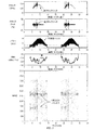
図3は、SOA電流の能動変調がない場合の掃引光信号のk−クロック周波数およびクロックジッタのプロットを含む。k−クロックは、同調性能不良を示唆する高レベルジッタを示す。さらに、可変同調レーザからの掃引光信号のパワー出力は、走査にわたって極めて不安定である。RINもまた高い。分光写真は、約2600および1300MHzにおいて掃引光信号中にパルスが存在することを示す。エネルギー分布は、レーザの同調帯域を通る走査過程にわたり変化するように見える。 FIG. 3 includes plots of the k-clock frequency and clock jitter of the swept optical signal in the absence of active modulation of the SOA current. The k-clock exhibits high level jitter that indicates poor tuning performance. Furthermore, the power output of the swept optical signal from the tunable laser is very unstable over the scan. RIN is also high. The spectrograph shows that there are pulses in the swept optical signal at about 2600 and 1300 MHz. The energy distribution appears to change over the scanning process through the tuning band of the laser.
図4は、レーザが2600MHz変調をSOAバイアス電流に適用することによって能動的にモード同期すること以外は図3と同一のプロットを示す。ここで、k−クロック周波数およびクロックジッタは、掃引光信号に対して低減したジッタを呈する。さらに、パワーは、帯域にわたる同調中はより一貫しており、RINはより低い。さらに、掃引光信号の分光写真を参照すると、1300MHzにおいて脈動がなく、2600MHzのみにおいて脈動がある。このことは、2つのパルスがキャビティ内を循環しながらレーザは安定して動作することを示唆する。 FIG. 4 shows the same plot as FIG. 3 except that the laser is actively mode-locked by applying 2600 MHz modulation to the SOA bias current. Here, the k-clock frequency and the clock jitter exhibit reduced jitter with respect to the swept optical signal. Furthermore, the power is more consistent during tuning across the band and the RIN is lower. Furthermore, referring to the spectrogram of the sweep light signal, there is no pulsation at 1300 MHz, and there is a pulsation only at 2600 MHz. This suggests that the laser operates stably with two pulses circulating in the cavity.
図5Aおよび5Bは、コンピュータシミュレーションの結果である。図5Aおよび5Bは、利得変調なしに掃引モード同期を呈する可変同調レーザを示す。この場合、レーザは、キャビティの1往復当たり2つのパルスで動作する。 5A and 5B are the results of computer simulation. 5A and 5B show a tunable laser that exhibits sweep mode locking without gain modulation. In this case, the laser operates with two pulses per round trip of the cavity.
図5Bの相関プロットは、掃引光源コヒーレンス長測定のコンピュータシミュレーションで、1つはSOA410を出射する光についてのプロット、1つは可変同調フィルタ412を出射する光についてのプロットであり、極端な経路差まで行われたものである。通常のコヒーレンス長測定は、ほぼゼロの経路差で行われる(2)。120mmにおいて(3)、パルスは、近傍のパルスと干渉している。240mmにおいて(4)、パルスは、キャビティ1往復分離れたパルスと、2パルス離れて干渉している。
The correlation plot of FIG. 5B is a computer simulation of swept source coherence length measurement, one for light exiting the
これらの2次コヒーレンス(3)(4)は、実際のOCTシステムにおいて問題となることがあり、キャビティ長またはその何分の1か(1往復当たりのパルスの数に依存する)にほぼ一致する長さにおける小さい迷走反射がOCT画像においてアーチファクトを生成する可能性がある。これらをなるべく排除するのが有用である。図6Aおよび6Bは、別のコンピュータシミュレーションの結果である。図6Aおよび6Bは、掃引モード同期が安定化された可変同調レーザを示す。この場合、レーザは、キャビティの1往復当たり1パルスのみで動作をするように制限され、ゲート掃引モード同期と呼ばれる。 These secondary coherences (3) and (4) can be problematic in practical OCT systems and roughly match the cavity length or a fraction of it (depending on the number of pulses per round trip) Small stray reflections in length can produce artifacts in OCT images. It is useful to eliminate these as much as possible. 6A and 6B are the results of another computer simulation. 6A and 6B show a tunable laser with stabilized sweep mode locking. In this case, the laser is limited to operate with only one pulse per round trip of the cavity and is referred to as gate sweep mode locking.
いくつかの例では、ゲートモード同期を使用して、実際のOCTシステムにおいて画像アーチファクトを生じさせうる「コヒーレンス繰返し」間の間隔を増大させる。 In some examples, gate mode synchronization is used to increase the spacing between “coherence iterations” that can cause image artifacts in a real OCT system.
レーザ100からの掃引光信号は、パルス間隔での繰返しコヒーレンスピークを有する。レーザが正常時に調波的にモード同期される場合、パルス間隔は、ゲートモード同期によって増加する。この場合、利得は、高調波よりもむしろキャビティの往復時間で、またはその典型的なパルス間隔よりも低い高調波で変調される。
The swept optical signal from
「ゲート制御された」モード同期は、キャビティの往復時間と同期する方形ポンプパルスバイアス電流(例えば、図1の符号490を参照)をSOA410に印加することによって達成される。ゲート制御されたモード同期により、レーザ100は、1往復当たり2パルスではなく、1往復当たり1パルスのみで動作するように制限される。この場合、2次コヒーレンスピークは240mm(2)にあり、120mmにはない。
“Gated” mode synchronization is achieved by applying to the SOA 410 a square pump pulse bias current (see, eg, 490 in FIG. 1) that is synchronized with the round trip time of the cavity. The gated mode synchronization limits the
図7Aおよび7Bは、別のコンピュータシミュレーションの同様の結果を示す。図7Aおよび7Bは、掃引モード同期が安定化された可変同調レーザを示す。この場合も、レーザは、1キャビティ往復当たり1パルスだけで動作するように制限される。 Figures 7A and 7B show similar results for another computer simulation. 7A and 7B show a tunable laser with stabilized sweep mode locking. Again, the laser is limited to operate with only one pulse per cavity round trip.
「ゲート制御された」モード同期は、キャビティの往復時間と同期する正弦波バイアス電流490をSOA410に印加することによって生じ、それによりレーザキャビティの利得となる。ゲート制御されたモード同期により、レーザ100は、もはや1往復当たり2パルスではなく、1往復当たり1パルスのみで動作するように制限される。この場合、2次コヒーレンスピークは、240mmのみにある。
“Gate-controlled” mode synchronization occurs by applying a sinusoidal bias current 490 to the
図8は、レーザの挙動を制御して安定させるために、線状キャビティレーザ掃引光源構成におけるキャビティ内位相変調器として能動モード同期システムが実現される第2の実施形態を例示する。能動位相変調は、低い光周波数への同調だけでなく、高い光周波数への高速同調を促進し、それにより安定かつ滑らかな上方および下方の同調を可能にする。 FIG. 8 illustrates a second embodiment in which an active mode-locking system is implemented as an intracavity phase modulator in a linear cavity laser swept source configuration to control and stabilize the behavior of the laser. Active phase modulation facilitates fast tuning to high optical frequencies as well as tuning to low optical frequencies, thereby allowing stable and smooth upward and downward tuning.
より詳細には、位相変調器470は、好ましくはキャビティの一端に向けて、キャビティに付加され、レーザのモード同期動作を制御する。一実施形態において、位相変調器は、SOA410とレンズ構造体416との間のベンチB上に設置される。好適な実施形態において、位相変調器は、SOAチップ410および、具体的には、別個の変調バイアス電流または電圧が供給される位相変調部と一体化され、それにより2部分SOA(利得、位相)をもたらす半導体チップである。一体化位相変調器は、一般に電流注入によって順方向にバイアスされるように機能するが、逆方向バイアスタイプも存在する。
More specifically, a
他の例において、位相変調器470は、LiNbO3のような外部変調器である。
In another example,
SOA利得飽和は、赤方偏移効果を有する。利得飽和は、能動位相変調レーザの実施形態が機能するのに必要ではない。 SOA gain saturation has a redshift effect. Gain saturation is not necessary for the active phase modulation laser embodiment to function.
好ましくは、位相変調器470に対する変調は、上記のように、キャビティ往復周波数の高調波周波数で変調信号を生成する無線周波数発生器460を含むバイアス電流変調システム455を使用して供給される。RF発生器460からの信号は、キャパシタ462を介して供給され、キャパシタ462は、バイアス電流源457に接続されたインダクタ458との組み合わせにより、位相変調器470に伝達される変調バイアス電流または電圧490を生成する。
Preferably, the modulation for
この例において典型的には、SOA410へのバイアス電流源456は、DC非変調信号を供給する。
Typically in this example, a bias
位相変調器470は、パルスが位相変調器470を通過する際に、それ自身の周波数シフト、(1/2π)dΦ/dtを与える。この周波数シフトは、パルスのタイミングに応じて、正または負となり得る。シフトが正となり、利得媒質飽和からの負周波数シフトを打ち消し得るので、正の同調速度に対して安定動作が達成される。
位相変調器470は、一例において、長いキャビティの往復時間の高次高調波で駆動される。また、キャビティ往復周波数の複雑な波形および高調波周波数を使用して位相変調器を駆動できる。正弦波変調の場合、変調位相は、Φpeakcos(2πfmodt)である。位相変調器は、Φpeakfmodである1往復当たりに最大周波数シフトを与える。周波数シフトの符号および大きさは、位相変調波形に対するパルスのタイミングに依存する。これは、実際のシステムの同調速度に、ある程度の許容を与える。
The
図9は、モード同期システムが、環状キャビティつまり自由空間レーザ掃引レーザ構成においてキャビティ内位相変調器として実施される別の実施形態を例示する。 FIG. 9 illustrates another embodiment in which the mode-locking system is implemented as an intracavity phase modulator in an annular cavity or free space laser swept laser configuration.
上記のように、位相変調器470は、SOA410とレンズ構造体416との間に位置する。
As described above, the
好ましくは、位相変調器470に対する変調は、上記のように、キャビティ往復周波数の高調波周波数で変調信号を生成してモード同期動作を制御する無線周波数発生器460を使用して供給される。RF発生器460からの信号は、キャパシタ462を介して供給され、キャパシタ462は、変調器バイアス電流源457に接続されたインダクタ458との組み合わせにより、位相変調器470に伝達される変調バイアス電流または電圧490を生成する。
Preferably, the modulation for
位相変調器470は、一例においてはLiNbO3のような外部変調器であり、または別の実施形態においてはSOAチップ410と一体化される。一体化位相変調器は、一般に電流注入によって順方向にバイアスされるように機能するが、逆方向バイアスタイプも存在する。
この例において典型的には、SOA410のためのバイアス電流源456が、DC非変調信号を供給する。
Typically in this example, a bias
一連の鏡910、912、914、および916が、環状キャビティ構成を形成する。図示の例において、可変同調フィルタ412は、環状構成においてSOA410とは反対の区間に位置する。図示の例において、第1のアイソレータ918は、可変同調フィルタ412の上流側に配置され、第2のアイソレータ920は、フィルタ412の下流側に配置される。これらのアイソレータは、可変同調フィルタ412によって反射される光からの寄生反射、およびアイソレータ920とSOA410の前部ファセットとの間の寄生反射を防止する。例示の実装例において、光出力は、部分反射鏡である鏡912を介して環状構成から取り出される。出力レンズ922は、掃引光信号のビームを出力光ファイバ320の入射ファセット上に集光する。出力光ファイバ320は、光をOCTシステムの干渉計50に搬送する。
A series of
一実装例において、鏡916もまた部分的に反射する。これにより、第2の出力つまり別出力の掃引光信号926を有する機会を提供する。掃引光信号926は、レンズ924によって平行にされる。
In one implementation,
いくつかの実装例においては、アイソレータ918および920は省略されてもよい。代わりに、可変同調フィルタ412を、光軸に対して傾斜させて、角度の切離しを提供し、すべての寄生反射をなくす。このような実施形態において、2つの平坦な鏡を有するファブリ・ペロ可変同調フィルタ412が使用される。
In some implementations,
図10は、モード同期システムが環状キャビティファイバレーザ掃引光源においてキャビティ内位相変調器として実装される別の実施形態を例示する。 FIG. 10 illustrates another embodiment in which the mode-locking system is implemented as an intracavity phase modulator in an annular cavity fiber laser swept light source.
より詳細には、可変同調フィルタ412は、上流ファイバアイソレータ918および下流ファイバ結合アイソレータ920に結合される。下流アイソレータ920は、波長分割多重結合器(WDM結合器)1012に結合される。このWDM結合器1012は、ポンプレーザ1010から光を取り込む。WDM結合器1012の出力は、キャビティ利得素子410として機能するエルビウム添加増幅器のようなファイバ増幅器に結合される。このファイバ増幅器は、ポンプレーザ1010からの光を使用してファイバ環状キャビティ内の光を増幅する。
More particularly,
ファイバ結合位相変調器470は、変調およびバイアス電圧455によって駆動される。位相変調器470は、好ましくはファイバによって、出力ファイバ320上の掃引光信号をOCTシステムの干渉計50に与える出力結合器1014に結合される。
Fiber coupled
位相変調レーザは、パルスの周波数シフトに対する利得飽和に左右されない。したがって、希土類添加ファイバのような長寿命の利得媒質410が、この環状レーザに使用される。利得媒質410はとりわけ、ErファイバおよびYbファイバの利得媒質410を含むであろう。ファイバに基づく実装例を本明細書中に記載するが、自由空間光学を使用して構成される変形も実装され得る。
Phase modulated lasers are not sensitive to gain saturation with respect to pulse frequency shift. Therefore, a long-lived
図11および12は、キャビティ内位相変調の環状レーザの性能に対する効果を示す2つのコンピュータシミュレーションの結果である。この場合、時間プロットの関数として加えられる位相シフトによって示されるように、レーザキャビティの往復時間に同期化された振幅πの正弦波位相変調を使用した。 FIGS. 11 and 12 are the results of two computer simulations showing the effect of intracavity phase modulation on the performance of an annular laser. In this case, a sinusoidal phase modulation of amplitude π synchronized to the round trip time of the laser cavity was used, as shown by the phase shift applied as a function of the time plot.
SOA利得の変調が、「利得および損失」プロットにおいて示される。CWキャビティ損失は、点線で示される。パルス化された波長掃引型レーザについての損失は、実線で示される。 The modulation of the SOA gain is shown in the “Gain and Loss” plot. CW cavity loss is indicated by a dotted line. The loss for a pulsed wavelength swept laser is indicated by a solid line.
レーザパルスは、正および負の同調速度の両方に対して歪みのない掃引光信号を生成する。 The laser pulse generates a distortion-free swept optical signal for both positive and negative tuning speeds.
負の同調速度(図11)において、パルス周波数ホッピングのほとんどは、SOA412の利得飽和から生じる屈折率変調が原因である。パルスは、正弦波の谷の近くで位相変調を通過する。正弦波の谷では、位相変調器からのさらなる周波数シフトはほとんどない。
At negative tuning speed (FIG. 11), most of the pulse frequency hopping is due to refractive index modulation resulting from
正の同調速度(図12)に関して、位相変調器からの周波数ホップは、利得飽和からのホップを打ち消す。これを生じさせるためには、位相対時間プロットにおいて示されるように、パルスが高い正の位相変化率、dΦ/dtを有する時に、パルスは変調器を通過しなければならない。 For positive tuning speed (FIG. 12), the frequency hop from the phase modulator cancels the hop from gain saturation. To cause this, the pulse must pass through the modulator when the pulse has a high positive phase change rate, dΦ / dt, as shown in the phase versus time plot.
図13は、モード同期システムが、線状キャビティレーザ掃引光源構成においてキャビティ内電気光学損失変調器1310として実装される別の実施形態を示す。
FIG. 13 shows another embodiment in which the mode-locking system is implemented as an intracavity electro-
より詳細には、電気光学損失変調器1310は、好ましくはキャビティの一端に向けて、キャビティ内に付加され、モード同期動作を制御する。電気光学損失変調器1310を使用してレーザキャビティの利得を変調する。一実施形態において、電気光学損失変調器(EOLM)1310は、SOA410とレンズ構造体416との間のベンチB上に設置される。介在レンズ1312は、SOA410とEOLM1300との間で光を結合する。
More specifically, an electro-
好ましくは、電気光学損失変調器1310に対する変調が、上記のように、キャビティ往復周波数の高調波周波数で変調信号を生成する無線周波数発生器460を含むバイアス電流変調システム455を使用して供給される。RF発生器460からの信号が、キャパシタ462を介して供給され、キャパシタ462は、EOLMバイアス電圧または電流1314に接続されたインダクタ458との組み合わせにより、電気光学損失変調器1310に伝達される変調バイアス電流または電圧490を生成する。
Preferably, the modulation for electro-
この例において典型的には、SOA410へのバイアス電流源456は、DC非変調信号を供給する。
Typically in this example, a bias
図14は、損失変調のない、つまりEOLMの透過率が100%である、正常掃引モード同期に対するコンピュータシミュレーションの結果を示す。この場合、レーザはキャビティ1往復当たり2パルスで動作する。 FIG. 14 shows the results of a computer simulation for normal sweep mode synchronization with no loss modulation, ie, EOLM transmittance of 100%. In this case, the laser operates with two pulses per cavity reciprocation.
図15は、損失変調のある掃引モード同期に対するコンピュータシミュレーションの結果を示す。図示の例において、レーザは、ゲート制御されたモード同期状態で動作する。損失変調は、時間の関数としてEOLMの透過率を示す一番下のグラフにおいて示される。レーザは、同じ負の同調速度(GHz/ns)において、動作を1往復当たり2パルスから1往復当たり1パルスに変化させる。 FIG. 15 shows the results of a computer simulation for sweep mode synchronization with lossy modulation. In the example shown, the laser operates in a gated mode-locked state. Loss modulation is shown in the bottom graph showing the transmission of EOLM as a function of time. The laser changes operation from 2 pulses per round to 1 pulse per round at the same negative tuning speed (GHz / ns).
この例は一種の能動「ゲート制御された」モード同期であるが、変調は、往復時間の任意の高調波と同期し得るであろうし、また正弦波波形である必要もないであろう。 An example of this is a kind of active “gated” mode locking, but the modulation could be synchronized with any harmonic of the round trip time and would not need to be a sinusoidal waveform.
例示の実施形態において、損失変調は、高速EOLM変調器1310によって行われる。他の実施形態において、導波路マッハ・ツェンダー損失変調器、定在波音響光学「モードロッカー(mode-locker)」、電界吸収型変調器は、線状または環状の構成のいずれかで実装される。ほとんどの技術は、変調がSOA410から切り離されることを要求するが、SOAチップとの一体化を可能とする技術もある。
In the exemplary embodiment, lossy modulation is performed by a
図16は、同期ポンピングを利用し、レーザキャビティの利得を変調することによってモード同期動作を制御および安定化する光コヒーレンス分析のためのモード同期レーザ掃引光源100を示す。
FIG. 16 shows a mode-locked laser swept
図示の線状キャビティ構成では、例示の実装例において、周波数同調ファブリ・ペロフィルタ412がキャビティの一端を画定する。
In the illustrated linear cavity configuration, in the illustrated implementation, a frequency tuned Fabry-
キャビティは、その一部を形成するファイバピグテール406の端部に位置する第2の出力反射器405まで延伸する。
The cavity extends to a
出力反射器405を通過する光は、光ファイバ320上または自由空間を介してOCTシステムの干渉計50に伝送される。
Light passing through the
半導体光増幅器(SOA)チップ利得素子410は、レーザキャビティ内に位置する。本実施形態において、SOAチップ410の入力ファセットおよび出力ファセットは、傾斜が付けられて反射防止(AR)コーティングされ、これら2つのファセットから平行なビームを提供する。
A semiconductor optical amplifier (SOA)
SOA410の各ファセットは、SOA410の一方のファセットから出射する光を結合するのに使用される連結レンズ構造体414、416を有する。第1のレンズ構造体414は、SOA410の後部ファセットと反射型ファブリ・ペロ可変同調フィルタ412との間で光を結合する。SOA410の出力ファセットつまり前部ファセットを出射する光は、第2のレンズ構造体416によってピグテール406のファイバ端部ファセットに結合される。
Each facet of the
同調制御器125は、同調帯域にわたり通過帯域光周波数を掃引するファブリ・ペロフィルタ412に同調電圧の関数を与える。好ましくは、光周波数は時間とともに線形に変化する。
例示の実施形態のモード同期システムは、ポンプレーザ1610に印加されるバイアスを変調するバイアス電流変調システム455を含む。
The mode locking system of the illustrative embodiment includes a bias
図示の例において、ポンプレーザ1610からの光は、WDM鏡1612および2つのさらなるレンズ1614、1616を使用してレーザキャビティに結合される。
In the illustrated example, light from the
より詳細には、ポンプレーザ1610から出射する光は、ポンプレンズ1616によって平行にされる。この光はWDM鏡1612に向けられる。WDM鏡1612は、ポンプ波長で光を反射するが、レーザキャビティから出射される光、すなわちレーザの同調帯域内の光を透過する。このようにして、レーザ光は、出力レンズ1614によって平行にされ、ファイバピグテール406に結合される。一方、ポンプ光はキャビティ内に結合される。
More specifically, light emitted from the
SOAレーザバイアス電流源456は、SOA410に供給されるバイアス電流のための直流電流を供給する。
The SOA laser bias
対照的に、ポンプレーザバイアス電流源455は、キャビティ往復周波数の高調波周波数を有する電気信号を生成する無線周波数発生器460を使用して、変調バイアス電流490を生成する。この周波数は、光がレーザ100のキャビティを往復するのに必要な時間に相当する。
In contrast, the pump laser bias
例示のレーザにおいて、これは1つの実装形態であるが、光がキャビティの一端の可変同調フィルタ412からピグテール406の端部にある出力反射器405に伝播するのに必要な時間の2倍に相当する。
In the exemplary laser, this is one implementation, but corresponds to twice the time required for light to propagate from the
RF発生器からの信号は、キャパシタ462を介して供給され、キャパシタ462は、インダクタ458との組み合わせにより、ポンプレーザ1610に伝達される変調バイアス電流490を生成する。
The signal from the RF generator is provided via a
この同期ポンピング実施形態において、例えば980nm半導体レーザチップであるポンプレーザ1610からの光は、より長い波長のSOA利得媒質410によって吸収される。SOA410は、場合によりCW電流源456からの直接電気ポンピングに加えて、ポンプレーザ1610によって「ポンプ」される。
In this synchronous pumping embodiment, light from a
この構成の利点は、利得切換機構を通るポンプレーザパルスが、電気変調パルスまたは正弦波駆動期間よりも極めて短くなる潜在能力を有することである。これは例えば、SOA利得が図1の実施形態に対して例示される直接電子変調によって得られるであろう期間よりも短い期間でポンプアップされ得ることを意味する。 The advantage of this configuration is that the pump laser pulse through the gain switching mechanism has the potential to be much shorter than the electrical modulation pulse or sinusoidal drive period. This means, for example, that the SOA gain can be pumped up in a shorter period than would be obtained by direct electronic modulation illustrated for the embodiment of FIG.
さらに、ポンプ1610は、一実施形態においてモード同期レーザである。これにより、モード同期レーザの自然なパルス化挙動が、複雑な高周波数電子駆動電流源を必要とせずにレーザキャビティを同期してポンプする。
Further, the
この技法は、他の実施形態においては環状キャビティ構成を使用して適用される。 This technique is applied in other embodiments using an annular cavity configuration.
図17は、ハイブリッド自由空間技法を使用する、同様の実施形態を示す。この例において、ポンプレーザ1610からの光は、WDMファイバ結合器1710を介してレーザキャビティ内に結合される。
FIG. 17 shows a similar embodiment using a hybrid free space technique. In this example, light from
図18は別の実施形態を示す。この実施形態のモード同期コントロールシステムは、レーザキャビティの利得を変調し、それによりモード同期動作を制御するために、環状キャビティレーザ掃引光源100において可飽和吸収器を使用して実装される。
FIG. 18 shows another embodiment. The mode-locked control system of this embodiment is implemented using a saturable absorber in the annular cavity laser swept
一連の鏡910、912、914、および916が、環状キャビティ構成をもたらす。図示の例において、可変同調フィルタ412は、環状構成においてSOA410とは反対の区間に位置する。図示の例において、第1のアイソレータ918は、可変同調フィルタ412の上流側に配置され、第2のアイソレータ920は、フィルタ412の下流側に配置される。これらのアイソレータは、可変同調フィルタ412によって反射される光からの寄生反射、およびアイソレータ920とSOA410の前部ファセットとの間の寄生反射を防止する。
A series of
例示の実施例において、掃引光信号は、部分反射鏡である鏡912を介して環状構成から取り出される。出力レンズ922は、掃引光信号のビームを出力光ファイバ320の入射ファセット上に集光する。出力光ファイバ320は、光をOCTシステムの干渉計50に搬送する。
In the illustrated embodiment, the swept optical signal is extracted from the annular configuration via
一実装例において、鏡916もまた部分的に反射する。これにより、第2の出力信号926を有する機会を提供する。第2の出力信号926は、レンズ924によって平行にされる。
In one implementation,
この実施形態は、受動モード同期の一構成を実装し、掃引動作を規則的な脈動へ安定化させるのに役立つ。これは、可飽和吸収器SA910をレーザキャビティに付加することによって達成される。環状構成において、これは、可飽和吸収器SAを、複数の鏡のうちの鏡910のような1つに接触させることによって最も容易に行われる。
This embodiment implements one configuration of passive mode synchronization and helps to stabilize the sweep operation to regular pulsations. This is accomplished by adding a saturable absorber SA910 to the laser cavity. In an annular configuration, this is most easily done by bringing the saturable absorber SA into contact with one such as
半導体可飽和吸収ミラー(SESAM)および炭素ナノチューブ(F.Wangら著、“Wideband-tuneable, Nanotube Mode-locked,Fibre Laser”、Nature Nanotechnology第3巻、2008年12月、738〜742ページ参照)は、適当な材料の2つの例である。2個の追加レンズ1810および1812が好ましくは環状キャビティに付加され、可飽和吸収ミラーSA910の内側および外側の光を結合する。レンズ1810および1812は、受動モード同期の条件である、吸収器SA910が利得媒質よりも容易に飽和するように、ビームウエストを低減する機能を果たす。Herman A.Haus著、“Mode-Locking of Lasers”、IEEE JOURNAL ON SELECTED TOPICS IN QUANTUM ELECTRONICS、第6巻、第6号、2000年11月/12月、1173〜1185ページを参照のこと。
Semiconductor saturable absorber mirrors (SESAM) and carbon nanotubes (see F. Wang et al., “Wideband-tuneable, Nanotube Mode-locked, Fiber Laser”, Nature Nanotechnology Volume 3, December 2008, pages 738-742) Two examples of suitable materials. Two
図19および20は、レーザキャビティの利得を変調するために、レーザ掃引光源100の線状キャビティにおいて可飽和吸収器を使用して実装されるモード同期制御システムのさらなる実施形態を示す。
19 and 20 show a further embodiment of a mode-locked control system implemented using a saturable absorber in the linear cavity of the laser swept
図19において、レーザキャビティは、可変同調フィルタ412からレンズ414、416、SOA410を通って可飽和吸収ミラーSESAMに延伸する。低飽和パワーを得るために、別のレンズ1910が付加され、ビームを可飽和吸収ミラーSESAM上に集光する。
In FIG. 19, the laser cavity extends from the
この実施形態において、出力は、可変同調フィルタ412を介して取り出される。より詳細には、可変同調フィルタに伝送された光は、レンズ1912によって出力光ファイバ320上に集光される。出力光ファイバ320は、掃引光信号をOCTシステムの干渉計50に搬送する。
In this embodiment, the output is extracted through a
図20は、同様の構成を示す。ただし、この実施形態は透過性可飽和吸収器1914を利用する。より詳細には、レンズ1910は、焦点が可飽和吸収器1914内にあるように、キャビティビームを集光する。可飽和吸収器1914の他方側の第2のレンズ1916は、ビームを再度平行にする。このビームは、レーザキャビティの端部を画定する鏡1918から反射される。
FIG. 20 shows a similar configuration. However, this embodiment utilizes a
この構成は、可飽和吸収器1914が、鏡1918のような端部鏡からキャビティの1/3に位置する場合に、キャビティにおける3パルスでの動作を促進するであろう。隣接するパルスは、可飽和吸収器1914内で衝突し、相互の吸収飽和を助長するであろう。
This configuration will facilitate operation with 3 pulses in the cavity when the
図21は、本発明の原理にしたがって構築された、モード同期レーザ光源100を使用する光コヒーレンス分析システム300を示す。
FIG. 21 illustrates an optical
モード同期動作が安定した可変同調レーザ掃引光源100が、光ファイバ320上に同調可能な掃引光信号を生成する。この掃引光信号は、干渉計50に伝送される。掃引光信号は、狭帯域放射を用いて走査帯域にわたって走査する。
A tunable laser swept
好ましくは、k−クロックモジュール250を使用して、光信号が走査または同調帯域にわたって同調または掃引される際に、クロック信号を等間隔の光周波数増分で生成する。
Preferably, the k-
本実施形態において、マッハ・ツェンダー型干渉計50を使用して、試料340からの光信号を分析する。掃引レーザ光源100からの同調信号が、ファイバ320上を90/10光結合器322に伝送される。組み合わされた同調信号は、システムの参照アーム326と試料アーム324との間の結合器322によって分割される。
In this embodiment, the optical signal from the sample 340 is analyzed using the Mach-
参照アーム326の光ファイバは、ファイバ端面328で終端する。参照アームファイバ端面328から出射する光は、いくつかの例示の実装例において、レンズ330によって平行にされ、次いで鏡332によって反射されて戻る。
The optical fiber of the
外部鏡332は、一例において、鏡までの距離を調節可能なファイバを有する(矢印334を参照)。この距離は、画像化される深さ範囲、すなわち参照アーム326と試料アーム324との間のゼロ経路長差の試料340における位置を決定する。この距離は、異なる試料プローブおよび/または画像化試料に対して調節される。参照鏡332から戻る光は、参照アームサーキュラ342に戻され、50/50ファイバ結合器346に向けられる。
The
試料アーム324上のファイバは、試料アームプローブ336において終端する。出射する掃引光信号は、プローブ336によって試料340上に集光される。試料340から戻る光は、試料アームサーキュラ341に戻され、50/50ファイバ結合器346に向けられる。参照アーム信号および試料アーム信号は、ファイバ結合器346において組み合わされ、干渉信号を生成する。干渉信号は、2つの検出器348を含む平衡受信器(バランスド受信器)によって、ファイバ結合器346の各出力において検出される。平衡受信器348からの電子干渉信号は、増幅器350によって増幅される。
The fiber on the
アナログ−デジタルコンバータシステム315を使用して、増幅器350からの干渉信号出力をサンプリングする。モード同期掃引光源100のk−クロックモジュール250から導かれる周波数クロックおよび掃引トリガー信号を、アナログ−デジタルコンバータシステム315が使用して、システムデータの取得を掃引光源システム100の周波数同調に同期させる。
An analog to
完全なデータセットが、集光プローブビームポイントを試料340にわたって空間的にラスター走査することによって、デカルト幾何(x−y)形式または円柱幾何(θ−z)形式で試料340から回収され、これらの点のそれぞれにおけるスペクトル応答がモード同期波長掃引型100の周波数同調から生成されると、デジタル信号プロセッサ380は、画像を再構築して試料340の2Dまたは3Dトモグラフィック再構築を行うために、データに対してフーリエ変換を行う。デジタル信号プロセッサ380によって生成されるこの情報は、映像モニタに表示される。
A complete data set is collected from the sample 340 in Cartesian (xy) or cylindrical (θ-z) format by spatially rastering the focused probe beam points across the sample 340, and these Once the spectral response at each of the points has been generated from the frequency tuning of the mode-locked
ある用途において、プローブは、血管に挿入され、動脈または静脈の内壁を走査するために使用される。他の例において、プローブには、血管内超音波(IVUS)、前向きIVUS(FLIVUS)、高密度焦点式超音波(HIFU)、圧力検知ワイヤおよび画像誘導治療装置などの他の分析治療手段(analysis modality)が含まれる。 In some applications, the probe is inserted into a blood vessel and used to scan the inner wall of an artery or vein. In other examples, the probe may include other analysis treatments such as intravascular ultrasound (IVUS), forward-looking IVUS (FLIVUS), high intensity focused ultrasound (HIFU), pressure sensing wires and image guided therapy devices. modality).
本発明は、その好適な実施形態を参照して特に示されかつ記載されたが、その好適な実施形態においては、添付の特許請求の範囲に包含される本発明の範囲を逸脱せずに、形態および詳細において種々の変更がなされ得ることが当業者によって理解されるであろう。例えば、本発明は、OCTまたは分光分析だけに関連して記載されたが、本発明はまた、IVUS、FLIVUS、HIFU、圧力検知ワイヤおよび画像誘導治療装置とともに応用され得るであろう。
なお、本発明は、実施の態様として以下の内容を含む。
〔態様1〕
レーザ掃引光源を提供する工程と、
前記レーザ掃引光源のモード同期動作を制御し、掃引光信号を生成する工程と、
前記掃引光信号を、参照アームと、試料が位置する試料アームとを有する干渉計に伝送する工程と、
前記試料アームおよび前記参照アームから戻る前記掃引光信号を組み合わせて、干渉信号を生成する工程と、
前記干渉信号を検出する工程と、
前記検出された干渉信号から前記試料の画像情報を生成する工程とを備えた、光コヒーレンス画像化方法。
〔態様2〕
態様1に記載の方法において、前記レーザ掃引光源の前記モード同期動作を制御する工程は、前記レーザ掃引光源のレーザキャビティ内の光を増幅する光利得素子へのバイアス電流を制御する工程を含む、光コヒーレンス画像化方法。
〔態様3〕
態様2に記載の方法において、前記バイアス電流を制御する工程は、前記バイアス電流を前記レーザキャビティ内の光の往復移動時間に基づく周波数で変調する工程を含む、光コヒーレンス画像化方法。
〔態様4〕
態様1に記載の方法において、前記レーザ掃引光源の前記モード同期動作を制御する工程は、前記レーザ掃引光源のレーザキャビティの利得を変調する工程を含む、光コヒーレンス画像化方法。
〔態様5〕
態様4に記載の方法において、前記レーザキャビティの利得は、前記レーザキャビティ内の光の往復移動時間に基づく周波数で変調される、光コヒーレンス画像化方法。
〔態様6〕
態様1に記載の方法において、前記レーザ掃引光源の前記モード同期動作を制御する工程は、前記レーザ掃引光源のレーザキャビティ内の光信号の位相を変調する工程を含む、光コヒーレンス画像化方法。
〔態様7〕
態様1に記載の方法において、前記レーザ掃引光源のモード同期動作を制御する工程は、レーザキャビティを制御して、当該レーザキャビティ内を循環するパルスの数を低減させる工程を含む、光コヒーレンス画像化方法。
〔態様8〕
同調帯域にわたり周波数同調される掃引光信号を生成する掃引レーザ光源であって、当該掃引レーザ光源のモード同期動作が制御される、掃引レーザ光源と、
前記掃引光信号を、参照アームと、試料に導く試料アームとの間で分割する干渉計と、
前記参照アームからおよび前記試料アームからの前記掃引光信号から生成される干渉信号を検出する検出器システムとを備えた、光コヒーレンス分析システム。
〔態様9〕
態様8に記載のシステムにおいて、前記掃引レーザ光源は、利得媒質と、前記掃引光信号の周波数を制御する同調素子とを含む、光コヒーレンス分析システム。
〔態様10〕
態様9に記載のシステムにおいて、前記掃引レーザ光源の前記モード同期動作が、前記利得媒質へのバイアス電流を変調することによって制御される、光コヒーレンス分析システム。
〔態様11〕
態様10に記載のシステムにおいて、前記バイアス電流は、前記キャビティ内の光の往復移動時間に基づく周波数で変調される、光コヒーレンス分析システム。
〔態様12〕
態様8に記載のシステムにおいて、前記掃引レーザ光源の前記モード同期動作は、前記掃引レーザ光源のレーザキャビティ内の位相変調器によって制御される、光コヒーレンス分析システム。
〔態様13〕
態様12に記載のシステムにおいて、前記位相変調器は、前記キャビティ内の光の往復移動時間に基づく周波数で変調される、光コヒーレンス分析システム。
〔態様14〕
態様8に記載のシステムにおいて、前記掃引レーザ光源の前記モード同期動作は、前記掃引レーザ光源のレーザキャビティの利得を変調することによって制御される、光コヒーレンス分析システム。
〔態様15〕
態様14に記載のシステムにおいて、前記レーザキャビティの前記利得は、前記レーザキャビティ内の光の往復移動時間に基づく周波数で変調される、光コヒーレンス分析システム。
〔態様16〕
態様8に記載のシステムにおいて、前記掃引レーザ光源のレーザキャビティが制御されて、前記レーザキャビティ内を循環するパルスの数を低減させる、光コヒーレンス分析システム。
〔態様17〕
モード同期掃引レーザ光源であって、
光を増幅するレーザキャビティ内の利得素子と、
前記レーザキャビティ用の可変同調素子と、
前記可変同調素子を同調帯域にわたり掃引して、掃引光信号を生成する同調制御器とを備え、
当該モード同期掃引レーザ光源のモード同期動作が制御される、モード同期掃引レーザ光源。
〔態様18〕
態様17に記載の光源において、前記レーザキャビティ内を循環するパルスの数を低減させるように、前記レーザ掃引光源の前記モード同期動作が制御される、モード同期掃引レーザ光源。
〔態様19〕
態様17に記載の光源において、前記レーザ掃引光源の前記モード同期動作を制御するように、前記レーザキャビティの利得が変調される、モード同期掃引レーザ光源。
〔態様20〕
態様17に記載の光源において、前記レーザ掃引光源の前記モード同期動作を制御するように、前記レーザキャビティの位相光信号が変調される、モード同期掃引レーザ光源。
The invention has been particularly shown and described with reference to preferred embodiments thereof, but in the preferred embodiments without departing from the scope of the invention as encompassed by the appended claims. It will be understood by those skilled in the art that various changes can be made in form and detail. For example, although the present invention has been described in connection with only OCT or spectroscopic analysis, the present invention could also be applied with IVUS, FLIVUS, HIFU, pressure sensing wires and image guided therapy devices.
In addition, this invention contains the following content as an aspect.
[Aspect 1]
Providing a laser swept light source;
Controlling the mode synchronization operation of the laser sweep light source to generate a sweep light signal;
Transmitting the swept optical signal to an interferometer having a reference arm and a sample arm on which the sample is located;
Combining the swept optical signal returning from the sample arm and the reference arm to generate an interference signal;
Detecting the interference signal;
An optical coherence imaging method comprising: generating image information of the sample from the detected interference signal.
[Aspect 2]
In the method according to
[Aspect 3]
The method according to
[Aspect 4]
2. The method of
[Aspect 5]
5. The method of
[Aspect 6]
The method according to
[Aspect 7]
The method of
[Aspect 8]
A swept laser light source that generates a swept light signal that is frequency tuned over a tuning band, wherein the mode locking operation of the swept laser light source is controlled;
An interferometer that splits the swept optical signal between a reference arm and a sample arm that leads to the sample;
An optical coherence analysis system comprising: a detector system for detecting an interference signal generated from the swept optical signal from the reference arm and from the sample arm.
[Aspect 9]
9. The system according to aspect 8, wherein the swept laser light source includes a gain medium and a tuning element that controls a frequency of the swept optical signal.
[Aspect 10]
10. The optical coherence analysis system according to aspect 9, wherein the mode-locking operation of the swept laser light source is controlled by modulating a bias current to the gain medium.
[Aspect 11]
11. The optical coherence analysis system according to
[Aspect 12]
The system according to aspect 8, wherein the mode-locking operation of the swept laser light source is controlled by a phase modulator in a laser cavity of the swept laser light source.
[Aspect 13]
13. The optical coherence analysis system according to aspect 12, wherein the phase modulator is modulated with a frequency that is based on a round trip time of light in the cavity.
[Aspect 14]
The system according to aspect 8, wherein the mode-locking operation of the swept laser light source is controlled by modulating a gain of a laser cavity of the swept laser light source.
[Aspect 15]
15. The optical coherence analysis system according to aspect 14, wherein the gain of the laser cavity is modulated with a frequency that is based on a round trip time of light within the laser cavity.
[Aspect 16]
9. The optical coherence analysis system according to aspect 8, wherein a laser cavity of the swept laser light source is controlled to reduce the number of pulses circulating in the laser cavity.
[Aspect 17]
A mode-locked sweep laser source,
A gain element in the laser cavity that amplifies the light;
A variable tuning element for the laser cavity;
A tuning controller that sweeps the variable tuning element over a tuning band to generate a swept optical signal;
A mode-locked sweep laser light source in which mode-lock operation of the mode-locked sweep laser light source is controlled.
[Aspect 18]
The mode-locked laser light source according to claim 17, wherein the mode-lock operation of the laser-swept light source is controlled so as to reduce the number of pulses circulating in the laser cavity.
[Aspect 19]
The mode-locked laser light source according to claim 17, wherein a gain of the laser cavity is modulated so as to control the mode-locking operation of the laser-swept light source.
[Aspect 20]
The mode-locked laser light source according to claim 17, wherein a phase optical signal of the laser cavity is modulated so as to control the mode-locking operation of the laser-swept light source.
Claims (10)
前記レーザ掃引光源のモード同期動作を制御し、掃引光信号を生成する工程と、
前記掃引光信号を、参照アームと、試料が位置する試料アームとを有する干渉計に伝送する工程と、
前記試料アームおよび前記参照アームから戻る前記掃引光信号を組み合わせて、干渉信号を生成する工程と、
前記干渉信号を検出する工程と、
前記検出された干渉信号から前記試料の画像情報を生成する工程とを備え、
前記レーザ掃引光源の前記モード同期動作を制御する工程は、前記レーザ掃引光源の可変同調素子を同調帯域にわたり掃引する間、前記レーザ掃引光源のレーザキャビティであって、1メートル長未満のキャビティ長を有するレーザキャビティ内の光を増幅する光利得素子へのバイアス電流を制御する工程を含み、前記バイアス電流を制御する工程は、前記バイアス電流を前記レーザキャビティ内の光の往復移動時間に相当する周波数またはその高調波の周波数で変調する工程を含む、光コヒーレンス画像化方法。 Providing a laser swept light source;
Controlling the mode synchronization operation of the laser sweep light source to generate a sweep light signal;
Transmitting the swept optical signal to an interferometer having a reference arm and a sample arm on which the sample is located;
Combining the swept optical signal returning from the sample arm and the reference arm to generate an interference signal;
Detecting the interference signal;
Generating image information of the sample from the detected interference signal,
The step of controlling the mode-locking operation of the laser swept light source includes a laser cavity of the laser swept light source having a cavity length of less than 1 meter while sweeping the tunable element of the laser swept light source over a tuning band. And a step of controlling a bias current to an optical gain element for amplifying light in the laser cavity, wherein the step of controlling the bias current has a frequency corresponding to a reciprocating time of light in the laser cavity. Or an optical coherence imaging method comprising the step of modulating at a frequency of its harmonics.
前記レーザ掃引光源のモード同期動作を制御し、掃引光信号を生成する工程と、
前記掃引光信号を、参照アームと、試料が位置する試料アームとを有する干渉計に伝送する工程と、
前記試料アームおよび前記参照アームから戻る前記掃引光信号を組み合わせて、干渉信号を生成する工程と、
前記干渉信号を検出する工程と、
前記検出された干渉信号から前記試料の画像情報を生成する工程とを備え、
前記レーザ掃引光源の前記モード同期動作を制御する工程は、前記レーザ掃引光源の可変同調素子を同調帯域にわたり掃引する間、前記レーザ掃引光源のレーザキャビティであって、1メートル長未満のキャビティ長を有するレーザキャビティの利得を変調する工程を含み、前記レーザキャビティの利得は、前記レーザキャビティ内の光の往復移動時間に相当する周波数またはその高調波の周波数で変調される、工程を含む、光コヒーレンス画像化方法。 Providing a laser swept light source;
Controlling the mode synchronization operation of the laser sweep light source to generate a sweep light signal;
Transmitting the swept optical signal to an interferometer having a reference arm and a sample arm on which the sample is located;
Combining the swept optical signal returning from the sample arm and the reference arm to generate an interference signal;
Detecting the interference signal;
Generating image information of the sample from the detected interference signal,
The step of controlling the mode-locking operation of the laser swept light source includes a laser cavity of the laser swept light source having a cavity length of less than 1 meter while sweeping the tunable element of the laser swept light source over a tuning band. Modulating the gain of the laser cavity, the gain of the laser cavity being modulated at a frequency corresponding to a reciprocation time of light in the laser cavity or a frequency of its harmonics. Imaging method.
前記掃引光信号を、参照アームと、試料に導く試料アームとの間で分割する干渉計と、
前記参照アームからおよび前記試料アームからの前記掃引光信号から生成される干渉信号を検出する検出器システムとを備え、
前記掃引レーザ光源は、利得媒質と、前記掃引光信号の周波数を制御する可変同調素子とを含み、前記掃引レーザ光源の前記モード同期動作が、前記可変同調素子が前記同調帯域にわたり周波数同調されている間に、前記利得媒質へのバイアス電流を変調することによって制御され、前記バイアス電流は、前記掃引レーザ光源のレーザキャビティであって、1メートル長未満のキャビティ長を有するレーザキャビティ内の光の往復移動時間に相当する周波数またはその高調波の周波数で変調される、光コヒーレンス分析システム。 A swept laser light source that generates a swept light signal that is frequency tuned over a tuning band, wherein the mode locking operation of the swept laser light source is controlled;
An interferometer that splits the swept optical signal between a reference arm and a sample arm that leads to the sample;
A detector system for detecting an interference signal generated from the swept optical signal from the reference arm and from the sample arm;
The swept laser light source includes a gain medium and a variable tuning element that controls the frequency of the swept optical signal, and the mode-locking operation of the swept laser light source is performed by frequency tuning the variable tuning element over the tuning band. The bias current is controlled by modulating a bias current to the gain medium, the bias current being a laser cavity of the swept laser light source and having a cavity length of less than 1 meter long. An optical coherence analysis system modulated at a frequency corresponding to the reciprocation time or a harmonic frequency thereof.
前記掃引光信号を、参照アームと、試料に導く試料アームとの間で分割する干渉計と、
前記参照アームからおよび前記試料アームからの前記掃引光信号から生成される干渉信号を検出する検出器システムとを備え、
前記掃引レーザ光源は、レーザキャビティであって、1メートル長未満のキャビティ長を有するレーザキャビティ内の位相変調器と、前記掃引光信号の周波数を制御する可変同調素子とを含み、
前記掃引レーザ光源の前記モード同期動作は、前記可変同調素子が前記同調帯域にわたり周波数同調されている間に、前記位相変調器によって制御され、前記位相変調器は、前記レーザキャビティ内の光の往復移動時間に相当する周波数またはその高調波の周波数で変調される、光コヒーレンス分析システム。 A swept laser light source that generates a swept light signal that is frequency tuned over a tuning band, wherein the mode locking operation of the swept laser light source is controlled;
An interferometer that splits the swept optical signal between a reference arm and a sample arm that leads to the sample;
A detector system for detecting an interference signal generated from the swept optical signal from the reference arm and from the sample arm;
The swept laser light source includes a laser cavity, a phase modulator in the laser cavity having a cavity length of less than 1 meter, and a tunable element that controls the frequency of the swept optical signal;
The mode-locking operation of the swept laser light source is controlled by the phase modulator while the variable tuning element is frequency tuned over the tuning band, the phase modulator reciprocating light in the laser cavity. An optical coherence analysis system that is modulated at a frequency corresponding to travel time or a frequency of its harmonics.
前記掃引光信号を、参照アームと、試料に導く試料アームとの間で分割する干渉計と、
前記参照アームからおよび前記試料アームからの前記掃引光信号から生成される干渉信号を検出する検出器システムとを備え、
前記掃引レーザ光源は、レーザキャビティであって、1メートル長未満のキャビティ長を有するレーザキャビティ内の利得媒質と、前記掃引光信号の周波数を制御する可変同調素子とを含み、
前記掃引レーザ光源の前記モード同期動作は、前記可変同調素子が前記同調帯域にわたり周波数同調されている間に、前記利得媒質の利得を変調することによって制御され、前記レーザキャビティの前記利得は、前記レーザキャビティ内の光の往復移動時間に相当する周波数またはその高調波の周波数で変調される、光コヒーレンス分析システム。 A swept laser light source that generates a swept light signal that is frequency tuned over a tuning band, wherein the mode locking operation of the swept laser light source is controlled;
An interferometer that splits the swept optical signal between a reference arm and a sample arm that leads to the sample;
A detector system for detecting an interference signal generated from the swept optical signal from the reference arm and from the sample arm;
The swept laser light source includes a laser cavity, a gain medium in the laser cavity having a cavity length of less than 1 meter, and a tunable element that controls the frequency of the swept optical signal;
The mode-locking operation of the swept laser light source is controlled by modulating the gain of the gain medium while the variable tuning element is frequency tuned over the tuning band, and the gain of the laser cavity is An optical coherence analysis system modulated at a frequency corresponding to a reciprocation time of light in a laser cavity or a harmonic frequency thereof.
光を増幅するレーザキャビティであって、1メートル長未満のキャビティ長を有するレーザキャビティ内の利得素子と、
前記レーザキャビティ用の可変同調素子と、
前記可変同調素子を同調帯域にわたり掃引して、掃引光信号を生成する同調制御器とを備え、
当該モード同期掃引レーザ光源のモード同期動作が、前記同調制御器によって前記可変同調素子が前記同調帯域にわたり掃引されている間に、前記レーザキャビティの利得を、前記レーザキャビティ内の光の往復移動時間に相当する周波数またはその高調波の周波数で変調することにより、制御される、モード同期掃引レーザ光源。 A mode-locked sweep laser source,
A Relais chromatography The cavity amplifying the light, and gain elements in the laser cavity having a cavity length less than 1 meter long,
A variable tuning element for the laser cavity;
A tuning controller that sweeps the variable tuning element over a tuning band to generate a swept optical signal;
While the mode-locking operation of the mode-locked sweep laser light source is being swept across the tuning band by the tuning controller, the gain of the laser cavity is adjusted to the reciprocation time of light in the laser cavity. A mode-locked swept laser source controlled by modulating at a frequency corresponding to or a harmonic frequency thereof.
光を増幅するレーザキャビティであって、1メートル長未満のキャビティ長を有するレーザキャビティ内の利得素子と、
前記レーザキャビティ内の位相変調器と、
前記レーザキャビティ用の可変同調素子と、
前記可変同調素子を同調帯域にわたり掃引して、掃引光信号を生成する同調制御器とを備え、
当該モード同期掃引レーザ光源のモード同期動作は、前記同調制御器によって前記可変同調素子が前記同調帯域にわたり掃引されている間に、前記レーザキャビティの位相光信号を、前記位相変調器が前記キャビティ内の光の往復移動時間に相当する周波数またはその高調波の周波数で変調することにより、制御される、モード同期掃引レーザ光源。 A mode-locked sweep laser source,
A Relais chromatography The cavity amplifying the light, and gain elements in the laser cavity having a cavity length less than 1 meter long,
A phase modulator in the laser cavity;
A variable tuning element for the laser cavity;
A tuning controller that sweeps the variable tuning element over a tuning band to generate a swept optical signal;
The mode-locking operation of the mode-locked sweep laser light source is such that the phase optical signal of the laser cavity is transmitted while the variable tuning element is swept over the tuning band by the tuning controller, and the phase modulator is moved into the cavity. A mode-locked sweep laser light source that is controlled by modulating at a frequency corresponding to the reciprocation time of the light or a harmonic frequency thereof.
Applications Claiming Priority (3)
| Application Number | Priority Date | Filing Date | Title |
|---|---|---|---|
| US12/979,225 | 2010-12-27 | ||
| US12/979,225 US20120162662A1 (en) | 2010-12-27 | 2010-12-27 | Actively Mode Locked Laser Swept Source for OCT Medical Imaging |
| PCT/US2011/067413 WO2012092290A1 (en) | 2010-12-27 | 2011-12-27 | Laser swept source with controlled mode locking for oct medical imaging |
Publications (3)
| Publication Number | Publication Date |
|---|---|
| JP2014501393A JP2014501393A (en) | 2014-01-20 |
| JP2014501393A5 JP2014501393A5 (en) | 2014-12-25 |
| JP6245698B2 true JP6245698B2 (en) | 2017-12-13 |
Family
ID=45491827
Family Applications (1)
| Application Number | Title | Priority Date | Filing Date |
|---|---|---|---|
| JP2013547620A Active JP6245698B2 (en) | 2010-12-27 | 2011-12-27 | Laser swept light source with controlled mode locking for OCT medical imaging |
Country Status (5)
| Country | Link |
|---|---|
| US (1) | US20120162662A1 (en) |
| EP (1) | EP2659555A1 (en) |
| JP (1) | JP6245698B2 (en) |
| CN (1) | CN103444020B (en) |
| WO (1) | WO2012092290A1 (en) |
Families Citing this family (22)
| Publication number | Priority date | Publication date | Assignee | Title |
|---|---|---|---|---|
| US10371499B2 (en) | 2010-12-27 | 2019-08-06 | Axsun Technologies, Inc. | Laser swept source with controlled mode locking for OCT medical imaging |
| US8929408B1 (en) * | 2012-01-23 | 2015-01-06 | Stc.Unm | Multi comb generation with a mode locked laser cavity |
| US9441944B2 (en) | 2012-05-16 | 2016-09-13 | Axsun Technologies Llc | Regenerative mode locked laser swept source for OCT medical imaging |
| CN102780153B (en) * | 2012-07-17 | 2013-12-11 | 清华大学 | Acousto-optic frequency sweeping laser based on acousto-optic deflection device |
| US8947672B2 (en) | 2012-07-26 | 2015-02-03 | Carl Zeiss Meditec, Inc. | Systems and methods for artifact suppression by frequency shifting or cavity length adjustment |
| US8836953B2 (en) * | 2012-11-07 | 2014-09-16 | Axsun Technologies, Inc. | OCT system with phase sensitive interference signal sampling |
| US9717422B2 (en) | 2012-12-12 | 2017-08-01 | Volcano Corporation | Sheath with optically interrogatable sensors |
| US20140176958A1 (en) | 2012-12-21 | 2014-06-26 | Axsun Technologies, Inc. | OCT System with Bonded MEMS Tunable Mirror VCSEL Swept Source |
| US8994954B2 (en) * | 2012-12-28 | 2015-03-31 | Axsun Technologies, Inc. | System and method for stabilizing mode locked swept laser for OCT medical imaging |
| WO2014121186A1 (en) * | 2013-02-01 | 2014-08-07 | The General Hospital Corporation | Apparatus and method which can include center-wavelength selectable, bandwidth adjustable, spectrum customizable, and/or multiplexable swept-source laser arrangement |
| GB2516679C (en) | 2013-07-30 | 2019-08-28 | Rushmere Tech Limited | Optical source |
| US9316483B2 (en) * | 2013-12-31 | 2016-04-19 | Axsun Technologies Llc | OCT swept laser with high coherence signal extraction |
| EP3362787A4 (en) | 2015-10-16 | 2019-05-22 | Dalhousie University | Systems and methods for swept source optical coherence tomographic vibrography |
| JP6619233B2 (en) * | 2016-01-08 | 2019-12-11 | 日本電信電話株式会社 | Temperature / concentration measuring device |
| CN106501840B (en) * | 2016-11-13 | 2023-04-11 | 中国科学院近代物理研究所 | Detector for measuring shape of longitudinal beam cluster of proton heavy ion beam |
| CN108539570A (en) * | 2017-03-01 | 2018-09-14 | 中兴通讯股份有限公司 | A kind of generation method and device of light pulse signal |
| TWI628925B (en) | 2017-03-23 | 2018-07-01 | 國立成功大學 | Photonic microwave time delay apparatus and method thereof |
| US10209477B1 (en) * | 2017-05-25 | 2019-02-19 | Lockheed Martin Coherent Technologies, Inc. | Systems and methods for reconfigurable micro-optic assemblies |
| EP3419123A1 (en) * | 2017-06-22 | 2018-12-26 | Koninklijke Philips N.V. | Vertical cavity surface emitting laser (vcsel) with improved gain-switching behavior |
| EP4096509A4 (en) * | 2020-01-31 | 2024-02-21 | Massachusetts Gen Hospital | Frequency-comb generation based on electro-optic phase-code mode-locking for circular-ranging oct |
| CN112665508B (en) * | 2020-12-08 | 2022-05-27 | 湖北工业大学 | Frequency domain signal reflectometer based on digital signal processing |
| CN112781504B (en) * | 2021-01-29 | 2023-07-07 | 太原理工大学 | Device and method for measuring optical fiber length by utilizing chaotic laser delay self-interference |
Family Cites Families (24)
| Publication number | Priority date | Publication date | Assignee | Title |
|---|---|---|---|---|
| US4918396A (en) * | 1989-04-05 | 1990-04-17 | At&T Bell Laboratories | Monitoring and/or control of optical amplifiers |
| US5509022A (en) * | 1991-09-20 | 1996-04-16 | The University Of Melbourne | Self-tuned mode-locked laser |
| KR100269040B1 (en) * | 1998-04-28 | 2000-10-16 | 서원석 | Wavelength-swept laser and method for its operation |
| US6192058B1 (en) * | 1998-09-18 | 2001-02-20 | Sarnoff Corporation | Multiwavelength actively mode-locked external cavity semiconductor laser |
| US6608711B2 (en) | 2000-03-03 | 2003-08-19 | Axsun Technologies, Inc. | Silicon on insulator optical membrane structure for fabry-perot MOEMS filter |
| US6373632B1 (en) | 2000-03-03 | 2002-04-16 | Axsun Technologies, Inc. | Tunable Fabry-Perot filter |
| US6345059B1 (en) * | 2000-10-25 | 2002-02-05 | Axsun Technologies, Inc. | Short cavity tunable laser with mode position compensation |
| JP3726676B2 (en) * | 2000-11-28 | 2005-12-14 | 日本電気株式会社 | External cavity mode-locked semiconductor laser device |
| US7050212B2 (en) * | 2002-11-22 | 2006-05-23 | California Institute Of Technology | Active mode-locked lasers and other photonic devices using electro-optic whispering gallery mode resonators |
| JP5567246B2 (en) * | 2003-10-27 | 2014-08-06 | ザ ジェネラル ホスピタル コーポレイション | Method and apparatus for performing optical imaging using frequency domain interferometry |
| WO2006042239A2 (en) * | 2004-10-06 | 2006-04-20 | The Regents Of The University Of California | Cascaded cavity silicon raman laser with electrical modulation, switching, and active mode locking capability |
| EP2264841B1 (en) * | 2005-01-20 | 2016-01-20 | Massachusetts Institute of Technology (MIT) | Mode locking methods and apparatus |
| US7415049B2 (en) | 2005-03-28 | 2008-08-19 | Axsun Technologies, Inc. | Laser with tilted multi spatial mode resonator tuning element |
| US7733923B2 (en) * | 2005-12-08 | 2010-06-08 | Alcatel-Lucent Usa Inc. | Wide-bandwidth mode-locked laser |
| JP5027429B2 (en) * | 2006-03-02 | 2012-09-19 | サンテック株式会社 | Dental optical tomographic image display system |
| US7813388B2 (en) * | 2006-12-06 | 2010-10-12 | Electronics And Telecommunications Research Institute | Self-pulsating laser diode |
| JP2009049123A (en) * | 2007-08-17 | 2009-03-05 | Fujifilm Corp | Optical semiconductor device and wavelength variable light source using the same and optical tomographic image acquiring apparatus |
| KR100942380B1 (en) * | 2007-11-23 | 2010-02-12 | 광주과학기술원 | Apparatus and Method for stabilizing carrier-envelope phase of laser pulses using direct locking method |
| JPWO2009133734A1 (en) * | 2008-05-02 | 2011-09-01 | オリンパス株式会社 | Optical inspection apparatus, electromagnetic wave detection method, electromagnetic wave detection apparatus, ecology observation method, microscope, endoscope, and optical tomographic image generation apparatus |
| JP5495506B2 (en) * | 2008-05-13 | 2014-05-21 | キヤノン株式会社 | Laser apparatus and optical tomographic imaging apparatus |
| US8564783B2 (en) | 2008-05-15 | 2013-10-22 | Axsun Technologies, Inc. | Optical coherence tomography laser with integrated clock |
| JP2010010172A (en) * | 2008-06-24 | 2010-01-14 | Fujifilm Corp | Wavelength-swept light source |
| US8494016B2 (en) * | 2008-07-29 | 2013-07-23 | Legato Laser Technology Ltd. | Mode locked laser system |
| JP5384978B2 (en) * | 2009-03-19 | 2014-01-08 | オリンパス株式会社 | Optical system including optical pulse generator |
-
2010
- 2010-12-27 US US12/979,225 patent/US20120162662A1/en not_active Abandoned
-
2011
- 2011-12-27 CN CN201180068327.7A patent/CN103444020B/en not_active Expired - Fee Related
- 2011-12-27 EP EP11808812.9A patent/EP2659555A1/en not_active Withdrawn
- 2011-12-27 JP JP2013547620A patent/JP6245698B2/en active Active
- 2011-12-27 WO PCT/US2011/067413 patent/WO2012092290A1/en active Application Filing
Also Published As
| Publication number | Publication date |
|---|---|
| WO2012092290A1 (en) | 2012-07-05 |
| CN103444020A (en) | 2013-12-11 |
| EP2659555A1 (en) | 2013-11-06 |
| JP2014501393A (en) | 2014-01-20 |
| US20120162662A1 (en) | 2012-06-28 |
| CN103444020B (en) | 2015-12-16 |
Similar Documents
| Publication | Publication Date | Title |
|---|---|---|
| JP6245698B2 (en) | Laser swept light source with controlled mode locking for OCT medical imaging | |
| US9800019B2 (en) | System and method for stabilizing mode locked swept laser for OCT medical imaging | |
| US10855053B2 (en) | OCT system with bonded MEMS tunable mirror VCSEL swept source | |
| US9441944B2 (en) | Regenerative mode locked laser swept source for OCT medical imaging | |
| US8526472B2 (en) | ASE swept source with self-tracking filter for OCT medical imaging | |
| US8670129B2 (en) | Filtered ASE swept source for OCT medical imaging | |
| JP6450743B2 (en) | Variable laser array system | |
| US8660164B2 (en) | Method and system for avoiding package induced failure in swept semiconductor source | |
| US9316483B2 (en) | OCT swept laser with high coherence signal extraction | |
| JP2015536462A (en) | OCT system using phase-sensitive interference signal sampling | |
| US8693508B2 (en) | Light source apparatus and image pickup apparatus equipped with same | |
| JP6280924B2 (en) | OCT system using tunable clock system for flexible data acquisition | |
| US10371499B2 (en) | Laser swept source with controlled mode locking for OCT medical imaging | |
| US10161738B2 (en) | OCT swept laser with cavity length compensation |
Legal Events
| Date | Code | Title | Description |
|---|---|---|---|
| A521 | Request for written amendment filed |
Free format text: JAPANESE INTERMEDIATE CODE: A523 Effective date: 20141107 |
|
| A621 | Written request for application examination |
Free format text: JAPANESE INTERMEDIATE CODE: A621 Effective date: 20141107 |
|
| A977 | Report on retrieval |
Free format text: JAPANESE INTERMEDIATE CODE: A971007 Effective date: 20150827 |
|
| A131 | Notification of reasons for refusal |
Free format text: JAPANESE INTERMEDIATE CODE: A131 Effective date: 20150901 |
|
| A521 | Request for written amendment filed |
Free format text: JAPANESE INTERMEDIATE CODE: A523 Effective date: 20151130 |
|
| A131 | Notification of reasons for refusal |
Free format text: JAPANESE INTERMEDIATE CODE: A131 Effective date: 20160426 |
|
| A521 | Request for written amendment filed |
Free format text: JAPANESE INTERMEDIATE CODE: A523 Effective date: 20160725 |
|
| A02 | Decision of refusal |
Free format text: JAPANESE INTERMEDIATE CODE: A02 Effective date: 20170110 |
|
| A521 | Request for written amendment filed |
Free format text: JAPANESE INTERMEDIATE CODE: A523 Effective date: 20170502 |
|
| A521 | Request for written amendment filed |
Free format text: JAPANESE INTERMEDIATE CODE: A523 Effective date: 20170626 |
|
| A911 | Transfer to examiner for re-examination before appeal (zenchi) |
Free format text: JAPANESE INTERMEDIATE CODE: A911 Effective date: 20170718 |
|
| A131 | Notification of reasons for refusal |
Free format text: JAPANESE INTERMEDIATE CODE: A131 Effective date: 20170822 |
|
| A521 | Request for written amendment filed |
Free format text: JAPANESE INTERMEDIATE CODE: A523 Effective date: 20170830 |
|
| A521 | Request for written amendment filed |
Free format text: JAPANESE INTERMEDIATE CODE: A523 Effective date: 20170927 |
|
| TRDD | Decision of grant or rejection written | ||
| A01 | Written decision to grant a patent or to grant a registration (utility model) |
Free format text: JAPANESE INTERMEDIATE CODE: A01 Effective date: 20171024 |
|
| A61 | First payment of annual fees (during grant procedure) |
Free format text: JAPANESE INTERMEDIATE CODE: A61 Effective date: 20171110 |
|
| R150 | Certificate of patent or registration of utility model |
Ref document number: 6245698 Country of ref document: JP Free format text: JAPANESE INTERMEDIATE CODE: R150 |
|
| R250 | Receipt of annual fees |
Free format text: JAPANESE INTERMEDIATE CODE: R250 |
|
| S111 | Request for change of ownership or part of ownership |
Free format text: JAPANESE INTERMEDIATE CODE: R313111 |
|
| R350 | Written notification of registration of transfer |
Free format text: JAPANESE INTERMEDIATE CODE: R350 |
|
| R250 | Receipt of annual fees |
Free format text: JAPANESE INTERMEDIATE CODE: R250 |
|
| R250 | Receipt of annual fees |
Free format text: JAPANESE INTERMEDIATE CODE: R250 |
|
| R250 | Receipt of annual fees |
Free format text: JAPANESE INTERMEDIATE CODE: R250 |