JP6243769B2 - Tomographic apparatus and method for operating the same - Google Patents
Tomographic apparatus and method for operating the same Download PDFInfo
- Publication number
- JP6243769B2 JP6243769B2 JP2014062113A JP2014062113A JP6243769B2 JP 6243769 B2 JP6243769 B2 JP 6243769B2 JP 2014062113 A JP2014062113 A JP 2014062113A JP 2014062113 A JP2014062113 A JP 2014062113A JP 6243769 B2 JP6243769 B2 JP 6243769B2
- Authority
- JP
- Japan
- Prior art keywords
- lumen
- imaging
- determination
- tomographic
- tomographic image
- Prior art date
- Legal status (The legal status is an assumption and is not a legal conclusion. Google has not performed a legal analysis and makes no representation as to the accuracy of the status listed.)
- Active
Links
Images


Description
本発明はカテーテルを用いて断層像の撮影を行う断層像撮影装置およびその制御方法に関する。 The present invention relates to a tomographic imaging apparatus that performs tomographic imaging using a catheter and a control method thereof.
光干渉断層撮影(OCT)や光周波数領域イメージング(OFDI)、血管内超音波イメージング(IVUS)を用いて血管内の断層撮影を行う断層像撮影装置が実用化されている。この種の断層像撮影装置では、光または超音波の送受信を行う信号送受信部を先端部に配したドライブシャフト(イメージングコア)がカテーテルの内腔に配置される。そして、血管に沿って配置されたカテーテルの内腔でドライブシャフトを介して信号送受信部を高速に回転させながらカテーテルの軸方向に沿って移動させて撮影を行うことで、血管の軸方向に沿った複数の断面画像を得ている。 A tomographic imaging apparatus that performs tomographic imaging in a blood vessel using optical coherence tomography (OCT), optical frequency domain imaging (OFDI), and intravascular ultrasound imaging (IVUS) has been put into practical use. In this type of tomography apparatus, a drive shaft (imaging core) in which a signal transmitting / receiving unit for transmitting / receiving light or ultrasound is arranged at the distal end is disposed in the lumen of the catheter. Then, in the lumen of the catheter disposed along the blood vessel, imaging is performed by moving the signal transmitting / receiving unit along the axial direction of the catheter while rotating the signal transmission / reception unit at high speed via the drive shaft. A plurality of cross-sectional images are obtained.
撮影対象の位置までカテーテルを血管内に挿入するためには、まず血管内の撮影対象の位置までガイドワイヤが挿入され、このガイドワイヤに沿ってカテーテルが送り込まれる。一般に、ガイドワイヤを通すための内腔が画像取得の妨げにならないように、ショートモノレールタイプのカテーテルが用いられる。しかしながら、ショートモノレールタイプのカテーテル場合、ガイドワイヤを通す内腔の長さが短いため、血管内へカテーテルを送り込もうとしても十分な押しが効かない場合がある。そのため、慢性完全閉塞(CTO)の部位などでは、カテーテルの血管内への送り込みが困難になる可能性がある。 In order to insert the catheter into the blood vessel up to the imaging target position, a guide wire is first inserted to the imaging target position in the blood vessel, and the catheter is fed along the guide wire. Generally, a short monorail type catheter is used so that a lumen for passing a guide wire does not interfere with image acquisition. However, in the case of a short monorail type catheter, since the length of the lumen through which the guide wire is passed is short enough to push the catheter into the blood vessel, the push may not work. Therefore, in a site of chronic total occlusion (CTO), it may be difficult to feed the catheter into the blood vessel.
そこで、CTOなど、送り込みに強さが求められるような部分では、ダブルルーメンタイプやロングモノレールタイプのカテーテルが用いられる。特許文献1に記載されているようなダブルルーメンタイプのカテーテルは、図7(a)に示されるように、シングルルーメンの領域701とダブルルーメンの領域702を有し、シングルルーメン領域でドライブシャフト703を引くことで画像を取得することを可能としている。
Therefore, double lumen type or long monorail type catheters are used in parts where strength is required for feeding, such as CTO. As shown in FIG. 7A, a double-lumen type catheter as described in
特許文献1に記載されたようなダブルルーメンタイプのカテーテルでは、シングルーメンの領域701においてガイドワイヤ704とドライブシャフト703とが同時に存在すると、両者が物理的に干渉する。たとえば、図7(b)のように、シングルルーメンの領域701にドライブシャフト703が存在する状況で、ガイドワイヤ704をシングルルーメンの領域701に押し込むと、両者が干渉する。特にドライブシャフト703が回転しているときにそのような干渉が生じると、カテーテル710あるいはドライブシャフト703を破損してしまう可能性がある。そこで、2つのX線不透過マーカ(以下、遠位マーカ711、近位マーカ712)を設け、X線透視を行ってガイドワイヤ704とドライブシャフト703の位置関係を確認しながら断層像の撮影手技を行うことになる。
In a double lumen type catheter as described in
より具体的には、
(1)術者は、ドライブシャフト703を近位マーカの位置までプルバックさせた状態でカテーテル710にガイドワイヤ704を通し、目的の部位までカテーテルを送り込む。
(2)術者が目的の部位をX線透視により確認しながら、ガイドワイヤ704を近位マーカ712の位置まで引き込む。
(3)ドライブシャフト703をシングルルーメンの領域701を通して撮影部位まで前進させた後、ドライブシャフト703を回転させながらプルバックして断層像を得る。
(4)再びガイドワイヤ704をシングルルーメンの領域701へ通し、カテーテル710を抜去する。
More specifically,
(1) The operator passes the
(2) The operator pulls the
(3) After the
(4) The
上記のような手技において、ガイドワイヤ704を近位マーカ712の位置まで引き込んだ後、再び前方へ送り込もうとした場合、ドライブシャフト703が近位マーカ712の位置まで戻っていないと、両者に干渉が生じる。シングルルーメンの領域701にドライブシャフト703とガイドワイヤ704が同時に存在してしまうためである。したがって、術者はX線透視画像を確認しながら、注意深く手技を行う必要があり、術者に大きな負担がかかる。
In the procedure as described above, when the
また、下肢などのように撮影領域が長い部位に対応したカテーテルでは、シングルルーメンの領域701(あるいは、遠位マーカ711と近位マーカ712との距離)が長くなる。そのため、撮影対象の領域を観察するためのX線透視領域が遠位マーカ711を含むような位置にあると近位マーカ712がX線透視領域から外れてしまう場合がある。そのような場合、術者は近位マーカ712の位置を確認することができなくなり、ガイドワイヤ704とドライブシャフト703の干渉を避けるためにそれらをどこまで引いたらよいのか分からなくなってしまう。また、近位マーカ712がX線透視領域に入るようにX線透視の領域をこまめに変更すればよいが、操作性が著しく劣化することは明らかである。
Further, in a catheter corresponding to a site having a long imaging region such as a lower limb, the single lumen region 701 (or the distance between the
本発明は上記課題に鑑みてなされたものであり、カテーテルのシングルルーメン領域においてガイドワイヤとドライブシャフトを出し入れして断層像の撮影を行う場合の術者への負担を軽減し、操作性を向上することを目的とする。 The present invention has been made in view of the above problems, and reduces the burden on the operator when taking a tomographic image by inserting and removing the guide wire and drive shaft in the single lumen region of the catheter, and improves operability. The purpose is to do.
上記の目的を達成するための本発明の一態様による断層像撮影装置は以下の構成を備える。すなわち、
医療用長尺体が通る第1の内腔と断層像撮影のための信号送受信部を有するイメージングコアが通る第2の内腔とを有する第1の領域と、前記第1の領域の先端側に接続され、前記第1および第2の内腔に連通する第3の内腔を有する第2の領域と、を備えたカテーテルを用いて断層像を撮影する断層像撮影装置であって、
前記信号送受信部を用いて断層像を取得する取得手段と、
前記取得手段により取得された前記断層像に前記医療用長尺体が写っているか否かを判定する第1判定手段と、
前記第1判定手段により、前記断層像に前記医療用長尺体が写っていないと判定された場合に前記イメージングコアの前記移動を許可し、前記断層像に前記医療用長尺体が写っていると判定された場合に前記イメージングコアの前記移動を不許可と判定する第2判定手段と、
前記イメージングコアの基端側と接続され、前記イメージングコアを移動するスライド機構と、
前記第2判定手段により許可と判定された場合には前記スライド機構を可動状態とし、前記第2判定手段により不許可と判定された場合には前記スライド機構をロックされた状態とする制御手段と、を備える。
In order to achieve the above object, a tomographic imaging apparatus according to one aspect of the present invention comprises the following arrangement. That is,
A first region having a first lumen through which a medical elongated body passes and a second lumen through which an imaging core having a signal transmission / reception unit for tomographic imaging passes, and a distal end side of the first region A tomographic imaging apparatus for imaging a tomographic image using a catheter comprising a second region having a third lumen connected to the first lumen and communicating with the first and second lumens,
Obtaining means for obtaining a tomographic image using the signal transmitting and receiving unit;
First determination means for determining whether or not the medical elongated body is reflected in the tomographic image acquired by the acquisition means;
By the first judging means, wherein allow the movement of the imaging core when the medical long body is determined not reflected, said medical long body is reflected in the tomographic image in the tomographic image Second determination means for determining that the movement of the imaging core is not permitted when it is determined that
A slide mechanism connected to the proximal end side of the imaging core and moving the imaging core;
Control means for placing the slide mechanism in a movable state when it is determined to be permitted by the second determination means, and for locking the slide mechanism when it is determined to be disapproved by the second determination means; , comprising a.
本発明によれば、カテーテルのシングルルーメン領域において医療用長尺体(例えば、ガイドワイヤ)とイメージングコアを出し入れして断層像の撮影を行う場合において、術者の負担が軽減され、操作性が向上する。 According to the present invention, when taking a tomographic image by inserting and removing a medical long body (for example, a guide wire) and an imaging core in a single lumen region of a catheter, the burden on an operator is reduced and operability is improved. improves.
以下、本発明を適用した断層像撮影装置として血管内超音波撮影装置を例示する。なお、本発明の適用は血管内超音波イメージング(IVUS)の撮影方式に限られるものではなく、たとえば光干渉断層撮影(OCT)や光周波数領域イメージング(OFDI)などの撮影方式にも本発明が適用可能であることは明らかである。 Hereinafter, an intravascular ultrasonic imaging apparatus will be exemplified as a tomographic imaging apparatus to which the present invention is applied. The application of the present invention is not limited to the imaging method of intravascular ultrasound imaging (IVUS), and the present invention is applicable to imaging methods such as optical coherence tomography (OCT) and optical frequency domain imaging (OFDI). Obviously it is applicable.
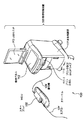
図1は本実施形態にかかる血管内超音波撮影装置100の外観構成を示す図である。図1に示すように、血管内超音波撮影装置100は、カテーテル101と、カテーテル101に挿入されたドライブシャフトのプルバックを行うスライド機構を備えたモータドライブユニット(以下、MDU102)と、操作制御装置103とを備える。MDU102と操作制御装置103とは、信号線104により接続されている。
FIG. 1 is a diagram showing an external configuration of an intravascular
カテーテル101は、その一部が直接、被検者の血管内に挿入され、その内腔には超音波振動子(以下、トランスデューサ)を含む信号送受信部が先端に設けられたドライブシャフトが挿通される。MDU102は、カテーテル101内のドライブシャフトを駆動する駆動部であり、信号送受信部の回転、移動を規定する。操作制御装置103は、血管内超音波撮影を行うにあたり、各種設定値を入力するための機能や、測定により得られたデータを処理し、断面画像として表示するための機能を備える。
A part of the
操作制御装置103において、111は本体制御部であり、測定により得られたデータを処理したり、処理結果を出力したりする。114はプリンタ/DVDドライブであり、本体制御部111における処理結果を印刷したり、データとして記憶したりする。112は操作パネルであり、ユーザはこの操作パネル112を介して、各種設定値の入力を行う。113はLCDモニタであり、本体制御部111における処理結果を表示する。
In the
次に、本実施形態の血管内超音波撮影装置100の機能構成について図2を用いて説明する。図2は、図1に示した血管内超音波撮影装置100の機能構成を示す図であり、血管内超音波撮影装置100が備えるカテーテル101、MDU102、操作制御装置103の内部構成を説明する図である。
Next, the functional configuration of the intravascular
カテーテル101は、先端内部に、超音波を送受信するためのトランスデューサを有する信号送受信部201を備えている。信号送受信部201は、コネクタ部202及びロータリジョイント211を介して超音波信号送受信器221と接続されている。信号送受信部201のトランスデューサは、カテーテル101の先端が血管内に挿入された状態で、信号送受信部201より送信されたパルス波に基づいて、超音波を血管の断面方向に送信するとともに、その反射波(エコー)を受信する。受信した反射波の信号は、コネクタ部202及びロータリジョイント211を介して超音波エコーとして信号送受信部201に送信される。
The
MDU102は、ロータリジョイント211、回転駆動装置212、直線駆動装置215を備える。カテーテル101内の信号送受信部201は、非回転部と回転部との間を結合するロータリジョイント211により回動自在に取り付けられており、ラジアル走査モータ213により回転駆動される。信号送受信部201が血管内を円周方向に回動することで、血管内の所定の位置における断面画像の生成に必要な超音波エコーを検出することができる。
The
なお、ラジアル走査モータ213の動作は制御部225からビデオ同調回路226を介して送信された制御信号に基づいて制御される。また、ラジアル走査モータの回転角度は、エンコーダ部214により検出される。エンコーダ部214において出力される出力パルスは、制御部225に入力され、信号送受信部201における送受信のタイミングに利用される。また、MDU102は、直線駆動装置215を備え、制御部225からの指示に基づいて、カテーテル101の挿入方向(前後方向)の動作を規定している。
The operation of the
超音波信号送受信器221は、送信波回路と受信波回路とを備える(不図示)。送信波回路は、制御部225から送信された制御信号に基づいて、カテーテル101内の超音波振動子に対してパルス波を送信する。また、受信波回路は、カテーテル101内のトランスデューサより超音波信号を受信する。受信された超音波信号はアンプ222により増幅された後、検波器223に入力され検波される。
The ultrasonic signal transmitter /
A/D変換器224は、検波器223より出力された超音波信号を30.6MHzで200ポイント分サンプリングして、1ラインのデジタルデータ(超音波エコーデータ)を生成する。なお、ここでは、30.6MHzとしているが、これは音速を1530m/secとしたときに、深度5mmに対して200ポイントサンプリングすることを前提として算出されたものである。したがって、サンプリング周波数は特にこれに限定されるものではない。
The A /
A/D変換器224にて生成されたライン単位の超音波エコーデータは制御部225に入力される。制御部225は、超音波エコーデータをグレースケールに変換することにより、血管内の各位置での断面画像を形成し、所定のフレームレートでLCDモニタ113に出力する。なお、制御部225は、不図示のコンピュータ(CPU)、ROM、RAM等を有し、CPUがROMまたはRAMに記憶されているプログラムを実行することにより、図6のフローチャートに示されるような処理を含む、血管内超音波撮影装置100の各種制御を実現する。
The line-unit ultrasonic echo data generated by the A /
次に、本実施形態のカテーテル101の構成について、図3、図4を参照して説明する。図3に示すように、カテーテル101は、血管内に挿入される長尺のカテーテルシース301と、ユーザが操作するために血管内に挿入されずユーザの手元側(基端側)に配置されるコネクタ302により構成される。図4に示されるように、カテーテルシース301の先端側はシングルルーメン領域321、他の領域はダブルルーメン領域322となっている。ダブルルーメン領域322は、B−B断面により示されるように、医療用長尺体としてのガイドワイヤ401が通る第1の内腔451と断層像撮影のためのイメージングコア(先端部に信号送受信部201を有するドライブシャフト402)が通る第2の内腔452とを有する領域である。また、シングルルーメン領域321は、ダブルルーメン領域322の先端側に接続され、ダブルルーメン領域322の第1の内腔451および第2の内腔452に連通する第3の内腔453を有する領域である。なお、本実施形態のカテーテルシース301の構造は図7に示した構造と類似であるが、ガイドワイヤ401や信号送受信部201が干渉域にあるか否かを判別するための近位マーカは無くてもよい。
Next, the structure of the
コネクタ302は、カテーテルシース301の基端に一体化して構成されたシースコネクタ302aとドライブシャフト402の基端に一体化して構成されたドライブシャフトコネクタ302bとからなる。シースコネクタ302aとカテーテルシース301の境界部には、耐キンクプロテクタ311が設けられており、これにより所定の剛性が保たれ、急激な変化によるカテーテルシース301の折れ曲がり(キンク)を防止することができる。また、ドライブシャフトコネクタ302bには、カテーテルシース301の管腔内全体を超音波伝達液で満たすため、シリンジ(不図示)等の取り付けが可能な注入ポート312が備えられている。ドライブシャフトコネクタ302bの基端は、MDU102と接続可能に構成されている。
The
カテーテルシース301の管腔内部には、超音波を送受信するトランスデューサを含む信号送受信部201と、それを回転させるための駆動力を伝達するドライブシャフト402とを備えるイメージングコア403がカテーテルシース301のほぼ全長にわたって挿通されている。本実施形態ではトランスデューサより体腔内組織に向けて超音波が送信されるとともに、当該トランスデューサにて体腔内組織からの反射波が受信される。なお、トランスデューサは、たとえば、矩形状あるいは円形状をしており、PZT等からなる圧電材の両面に、電極を蒸着することにより形成されている。トランスデューサは、ドライブシャフト402が回転ムラを引き起こさないように、回転軸方向の中心付近に位置するよう設置されている。また、ドライブシャフト402はコイル状に形成され、その内部には信号線が配され、信号送受信部201(トランスデューサからコネクタ302まで伸びている。
Inside the lumen of the
ドライブシャフト402は、カテーテルシース301の管腔内において回転及びスライド動作することが可能であり、柔軟で、かつ回転をよく伝達できる特性をもつ、例えば、ステンレス等の金属線からなる多重多層密着コイル等により構成されている。ドライブシャフト402の回転により360度にわたる観察が可能となるが、更に軸方向に沿った範囲を観察するには、ドライブシャフト402を軸方向にスライドさせればよい。
The
図4では、図3に示されている状態から、ドライブシャフト402をカテーテルシース301に対して相対的に491スライドさせた様子が示されている。図4に示すように、シースコネクタ302aを固定した状態で、ドライブシャフトコネクタ302bを基端側に(矢印491方向に)スライドさせれば、内部のドライブシャフト402やその先端に固定された信号送受信部201が軸方向にスライドすることとなる。この軸方向のスライドは、MDU102の回転駆動装置212をユーザが手動により軸方向へ移動させて行ってもよいし、直線駆動装置215を駆動して行ってもよい。また、直線駆動装置215の駆動はプログラミングされたパターンに従って制御部225が自動的に行ってもよいし、ユーザのスイッチ操作による直線駆動装置125のオンオフにより行われても良い。
FIG. 4 shows a state in which the
次に、以上のような構成を備えた本実施形態の血管内超音波撮影装置100の動作について図5、図6を参照して説明する。図5は、カテーテルシース301のシングルルーメン領域及びその付近におけるイメージングコア403(信号送受信部201とドライブシャフト402)との位置関係に応じて取得される断層像の例を示す図である。図6は、本実施形態の血管内超音波撮影装置100による断層像撮影動作を説明するフローチャートである。なお、以下の動作手順では、断層像撮影の開始にあたって少なくともイメージングコア403がダブルルーメン領域322に退避していることを前提としている。
Next, the operation of the intravascular
まず、ステップS601において、制御部225は、MDU102のスライド機構をロックする。上述のようにスライド機構はドライブシャフト402の基端側と接続され、ドライブシャフト402(イメージングコア)を前後方向へ移動する。MDU102のスライド機構がロックされた状態とは、MDU102のスライド機構に関するホールド機能がオン状態となり、外力等により容易にドライブシャフト402が移動しないようにされた状態である。また、スライド機構がロックされた状態においては、直線駆動装置215による前後方向への移動が不許可となり、たとえば術者による操作パネル112へのスライドの指示操作に応じた入力信号は受け付けられず、無視される。
First, in step S601, the
ステップS602において、制御部225は、イメージングコアを回転させ、信号送受信部201を用いて少なくとも1枚の断層像を取得する。このときのイメージングコアの回転速度は、診断用の画像を取得するための回転速度より低速であってもよい。ガイドワイヤ401とイメージングコアとの位置関係が干渉状態にあるかどうかがわからないため、低速で回転させた方が安全だからである。イメージングコアとガイドワイヤ401がたとえば図5(a)に示されるような位置にあった場合、断層像501が得られる。なお、図5に示される断層像501〜503は説明をわかりやすくするために模式的に描かれた図であって、実際に得られる断層像を正確に示したものではないことに留意されたい。断層像の取得位置にガイドワイヤが含まれる場合、断層像501に示されるように、扇形に深部方向へ延びるガイドワイヤの影(ガイドワイヤによる後方の画像の抜け)が観察される。なお、血管壁511の内部にカテーテルシース301の管壁、第1の内腔451および第2の内腔452は、一般には像として観察されないようにマスクされているので、図5では点線で示されている。なお、像513は信号送受信部201自身の外形である。ステップS603において、制御部225はこのような断層像を解析し、断層像にガイドワイヤ401に対応する影512(像の抜け)が存在するか否か(ガイドワイヤ401が写っているか否か)を判定する。
In step S602, the
断層像501のように、ガイドワイヤ401の影512が写っている場合、ガイドワイヤ401はシングルルーメン領域321に挿通されていると判断され、処理はステップS604からステップS605へ進む。図5(a)のように、ガイドワイヤ401がシングルルーメン領域321に存在する場合にイメージングコアをシングルルーメン領域321に送り込むと、ガイドワイヤ401とイメージングコアとの間に機械的な干渉が生じ、カテーテルを破損する可能性がある。したがって、制御部225は、MDU102の直線駆動装置215が提供するスライド機構をロックされた状態に維持する。たとえば、直線駆動装置215のブレーキをオン状態とする。更に、ステップS606において、制御部225は、ガイドワイヤ401のシングルルーメン領域からの後退が十分でないことを、LCDモニタ113を用いて報知することにより、ガイドワイヤ401をさらに引き戻すよう指示する。その後、処理はステップS602に戻り、ステップS602〜S606の処理が、ガイドワイヤ401の像が検出されなくなるまで繰り返される。
When the
術者がガイドワイヤ401を引き戻し、ガイドワイヤ401とイメージングコアの位置が図5(b)のような状態になると、断層像502に示されるようにガイドワイヤ401に対応する影が存在しなくなり、処理はステップS604からステップS610へ進む。ステップS610において、制御部225は、スライド機構のロックされた状態を解除して可動状態とする。この状態で、術者は手動で回転駆動装置212をスライドさせてイメージングコアをシングルルーメン領域321に送り込むことができる。或いは、直線駆動装置215による前進動作が許可され、術者は、スイッチ操作などによりイメージングコア403を前進させることができるようになる。なお、ステップS610とステップS611の間にステップS626の処理が入っていてもよい(不図示)。この場合、ステップS610からただちにステップS626へ処理が進み、ガイドワイヤ401の送り込みを不許可とし、ガイドワイヤ401の送り込みを不許可とする旨の表示を行った上で、ステップS611に進むこととなる。ステップS611において、制御部225は、LCDモニタ113に、イメージングコア403の送り込みが可能であることを表示する。この表示の後、術者は、手動またはスイッチ操作によりイメージングコアの信号送受信部201を撮影対象の位置まで送り込むことができる。
When the surgeon pulls back the
術者は操作パネル112を介して撮影の実行を指示する。制御部225は、この指示を受け付けると、MDU102を制御して診断用の撮影を実行する。すなわち、制御部225は、回転駆動装置212によりイメージングコア403を高速回転させるとともに直線駆動装置215によりイメージングコア403をプルバックさせて、所定の範囲にわたる血管の断層像を撮影する。診断用の撮影が終了すると処理はステップS613からステップS620へ進む。
The surgeon instructs execution of imaging via the
ステップS613における撮影終了の判断について説明する。撮影終了の判断の方法としては、たとえば、以下の(1)〜(5)が挙げられる。なお、ステップS613では(1)〜(5)のいずれかによって撮影終了と判断された場合に、処理をステップS620へ分岐するものとする。なお、以下の(1)〜(5)の判断方法は、MDU102により自動的にプルバックする場合、手動でプルバックする場合のいずれにも適用できる。
(1)断層像の撮影範囲(軸方向の距離)を設定しておき、診断用の画像の撮影開始から設定された距離がプルバックされた場合に撮影終了と判断する。たとえば、撮影範囲が軸方向に10cmであれば、直線駆動装置215がイメージングコア403を10cmプルバックした時点で撮影終了と判断される。
(2)診断用画像の撮影の開始から所定時間が経過したことが検出された場合に撮影終了と判断する。たとえば、診断用の画像の撮影開始からタイマを起動し、そのタイマに予め設定された時間が経過した時点で診断用の断層像の撮影を終了する。
(3)診断用画像の解析によりガイドワイヤ401が検出された場合に撮影終了と判断する。
(4)MDU102の限界までプルバックされたことが検出された場合に撮影終了と判断する。
(5)撮影終了を指示するスイッチがユーザにより操作された場合に、撮影終了と判断する。
The determination of the end of shooting in step S613 will be described. Examples of the method for determining the end of shooting include the following (1) to (5). Note that in step S613, if it is determined that shooting is ended by any one of (1) to (5), the process is branched to step S620. The following determination methods (1) to (5) can be applied to either the case of automatically pulling back by the
(1) A tomographic image capturing range (distance in the axial direction) is set, and when the set distance from the start of diagnosis image capturing is pulled back, it is determined that the capturing has ended. For example, if the imaging range is 10 cm in the axial direction, it is determined that the imaging is finished when the
(2) When it is detected that a predetermined time has elapsed from the start of imaging of the diagnostic image, it is determined that imaging has been completed. For example, a timer is started from the start of imaging of a diagnostic image, and imaging of a diagnostic tomographic image is terminated when a time preset in the timer has elapsed.
(3) When the
(4) When it is detected that the pull back has been reached to the limit of the
(5) When the switch for instructing the end of shooting is operated by the user, it is determined that the shooting has ended.
ステップS620では、制御部225は、イメージングコア403がMDU102のプルバックの限度まで引かれた状態か否かを判定する。イメージングコア403が引ききられている場合は、イメージングコア403の先端が干渉域(シングルルーメン領域321)を抜けたものと判断し、処理をステップS624へ進める。イメージングコア403がプルバックの限度に達していない場合は、処理ステップS621へ進む。ステップS621では、ガイドワイヤ401とイメージングコア403との干渉の発生の可能性を判定するための断層像撮影が行われる。すなわち、ステップS602と同様に、制御部225は、ガイドワイヤ401の存在を確認するための断層像を取得する。ステップS602で述べたように、このときの回転速度は診断用の断層像の撮影における回転速度より遅くしてもよい。そして、ステップS622において、制御部225は、ステップS620で取得した断層像を解析し、その断層像にガイドワイヤ401に対応する像が存在するか否かを判定する。たとえば、診断用の断層像撮影を終えた後、図5(c)に示されるような位置(シングルルーメン領域321内)にイメージングコア403があると、断層像503に示されるように断層像にはガイドワイヤ401に対応する影は存在しない。すなわち、ステップS621の撮影により得られた断層像にガイドワイヤの像が存在しない場合は、イメージングコアがシングルルーメン領域321に存在している可能性がある。この場合、シングルルーメン領域321にガイドワイヤ401を送り込むと、イメージングコア403とガイドワイヤ401が干渉する可能性がある。
In step S620, the
したがって、ステップS622における解析の結果、ガイドワイヤ401の像が存在しないと判定された場合には処理はステップS623からステップS626に進み、制御部225は、ガイドワイヤ401の送り込みを不許可とする旨の表示および/またはイメージングコア403をさらに引き込む指示をLCDモニタ113に行う。そして、処理はステップS620に戻り、上述した処理が繰り返される。
Therefore, if it is determined as a result of the analysis in step S622 that the image of the
その後、術者が、ガイドワイヤ401の像が断層像に写る位置までイメージングコア403を引き戻し、ステップS621の解析の結果、断層像にガイドワイヤ401の像が存在すると判定されると、処理はステップS623からステップS624へ進む。ステップS624において、制御部225は、断層像の撮影を終了し、ステップS601と同様にMDU102のスライド機構をロックする。そして、ステップS625において、制御部225は、ガイドワイヤ401の先端側への送り込みを許可する旨を、LCDモニタ113を用いて報知する。なお、ステップS613の撮影終了の判断において、上述した(3)または(4)により撮影終了が判断された場合は、ステップS613からただちにステップS626へ処理が進むようにしてもよい。また、(5)により撮影終了が判断された場合に、撮影終了を指示するスイッチが操作された以降の撮影(ステップS620以降の処理)を行わないようにしてもよい。その場合、スイッチが操作された時点の断層像の解析結果にガイドワイヤ401が検出されておらず、MDU102のプルバックの限界まで引かれた状態でもなければ、イメージングコア403をMDU102のプルバック限界まで引き込むような指示をLCDモニタ113などにより行うようにしてもよい。
Thereafter, when the operator pulls back the
なお、上記実施形態では、ステップS622、S623において、ガイドワイヤ401に対応する像の存在を判定したが、これに限られるものではない。ガイドワイヤ401の送り込みはイメージングコアの信号送受信部201がダブルルーメン領域322に戻っていることを確認できればよい。したがって、たとえば、断層像にガイドワイヤ401を相通するための内腔(第1の内腔451)の像が映るようにして、その存在を検出できた場合にガイドワイヤ401の送り込みを許可し、MDU102のスライド機構をロックされた状態とするようにしてもよい。或いは、図7の近位マーカ712のようなマーカ(X線透過でもX線不透過でもよい)をダブルルーメン領域322に設けておき、これが断層像に映った場合にガイドワイヤ401の送り込みを許可し、MDU102のスライド機構をロックされた状態とするようにしてもよい。
In the above embodiment, the presence of an image corresponding to the
また、上記実施形態では、ガイドワイヤの写りこみを確認するための断層像撮影(ステップS602とS621)におけるイメージングコアの回転速度を診断用の断層像撮影(ステップS612)における回転速度よりも低速とした。しかしながら、イメージングコアの回転速度を切り替えることは必須ではなく、図6のフローチャートで示されている全ての断層像撮影を同じ回転速度(ステップS612における診断撮影用の回転速度)で行ってもよい。 In the above embodiment, the rotational speed of the imaging core in tomographic imaging (steps S602 and S621) for confirming the reflection of the guide wire is set lower than the rotational speed in diagnostic tomographic imaging (step S612). did. However, it is not essential to switch the rotational speed of the imaging core, and all tomographic imaging shown in the flowchart of FIG. 6 may be performed at the same rotational speed (rotational speed for diagnostic imaging in step S612).
また、上記実施形態では、イメージングコアやガイドワイヤの送り込みの許可、不許可をLCDモニタ113に表示して行うようにしたが、MDU102に表示部を設けて表示するようにしてもよい。この場合、MDU102には、複数のLEDランプによる報知であってもよい。また、イメージングコアやガイドワイヤの送り込みの許可、不許可を音により報知するようにしてもよいことは明らかである。さらに、ステップS602やステップS620で撮影された断層像(断層像501〜503)をLCDモニタ113に表示するようにしてもよい。
Further, in the above-described embodiment, the permission or non-permission of the feeding of the imaging core or the guide wire is displayed on the LCD monitor 113. However, the display unit may be provided on the
また、上記実施形態では、診断用の断層像の撮影終了でMDU102によるドライブシャフト402の引き込みを停止しているが、これに限られるものではない。たとえば、診断用の撮影を終了した後もドライブシャフト402の引き込みを継続させ、ステップS622でガイドワイヤ401の写りこみが検出されるまでステップS620〜S623の処理を繰り返すようにしてもよい。すなわち、制御部225は、診断用の断層像の撮影を終えた後、MDU102のスライド機構を駆動して、断層像にガイドワイヤ401が写っていると判定されるまでドライブシャフト402を引き戻すようにしてもよい。このような制御によれば、診断用の断層像を撮影した後に自動的にドライブシャフト402が安全な位置まで退避するので、操作性が向上する。
In the above-described embodiment, the pull-in of the
以上のように、本実施形態によれば、ステップS602で取得された断層像にガイドワイヤ401が写っているか否かを判定し、その判定の結果に基づいて、カテーテル内におけるドライブシャフト402の前後方向への移動の許可、不許可が判定される。そのため、図7に示したような近位マーカを用いてドライブシャフト402の位置を確認する必要が無くなる。すなわち、X線透視の範囲に近位マーカが存在しなくても、ドライブシャフト402の送り込みを安全に行うことができる。また、本実施形態では、診断用の断層像の撮影において、診断用の断層像へガイドワイヤが写り込む場合について説明してきたが、ガイドワイヤに限られるものではない。たとえば、カテーテル101とは別の医療用カテーテルや、内視鏡などが挙げられ、本発明で用いられる画像診断用のカテーテル101と併用される医療用の長尺体であれば、何れであってもかまわない。
As described above, according to the present embodiment, it is determined whether or not the
100:血管内超音波撮影装置、 101:カテーテル、 102:MDU、 103:走査制御装置、 201:信号送受信部、 301:カテーテルシース、 302:コネクタ、 401:ガイドワイヤ、 402:ドライブシャフト、 451:第1の内腔、 452:第2の内腔、 453:第3の内腔 DESCRIPTION OF SYMBOLS 100: Intravascular ultrasonic imaging apparatus, 101: Catheter, 102: MDU, 103: Scanning control apparatus, 201: Signal transmission / reception part, 301: Catheter sheath, 302: Connector, 401: Guide wire, 402: Drive shaft, 451: First lumen, 452: Second lumen, 453: Third lumen
Claims (14)
前記イメージングコアの基端側と接続され、前記イメージングコアを移動するスライド機構と、
前記信号送受信部を用いて断層像を取得する取得手段と、
前記取得手段により取得された前記断層像に前記医療用長尺体が写っているか否かを判定する第1判定手段と、
前記第1判定手段により、前記断層像に前記医療用長尺体が写っていないと判定された場合に前記イメージングコアの前記移動を許可し、前記断層像に前記医療用長尺体が写っていると判定された場合に前記イメージングコアの前記移動を不許可と判定する第2判定手段と、
前記第2判定手段により許可と判定された場合には前記スライド機構を可動状態とし、前記第2判定手段により不許可と判定された場合には前記スライド機構をロックされた状態とする制御手段と、を備えることを特徴とする断層像撮影装置。 A first region having a first lumen through which a medical elongated body passes and a second lumen through which an imaging core having a signal transmission / reception unit for tomographic imaging passes, and a distal end side of the first region A tomographic imaging apparatus for imaging a tomographic image using a catheter comprising a second region having a third lumen connected to the first lumen and communicating with the first and second lumens,
A slide mechanism connected to the proximal end side of the imaging core and moving the imaging core;
Obtaining means for obtaining a tomographic image using the signal transmitting and receiving unit;
First determination means for determining whether or not the medical elongated body is reflected in the tomographic image acquired by the acquisition means;
By the first judging means, wherein allow the movement of the imaging core when the medical long body is determined not reflected, said medical long body is reflected in the tomographic image in the tomographic image Second determination means for determining that the movement of the imaging core is not permitted when it is determined that
Control means for placing the slide mechanism in a movable state when it is determined to be permitted by the second determination means, and for locking the slide mechanism when it is determined to be disapproved by the second determination means; , tomography apparatus, characterized in that it comprises a.
術者の操作による入力信号に応じて、前記スライド機構を駆動して前記イメージングコアを移動させ、
前記第2判定手段により不許可と判定されている間、前記入力信号を無視することを特徴とする請求項1に記載の断層像撮影装置。 The control means includes
In response to an input signal by an operator's operation, the slide mechanism is driven to move the imaging core,
While it is determined that the prohibition by the second judging means, tomography apparatus according to claim 1, characterized in that ignoring the input signal.
前記信号送受信部を用いて断層像を取得する取得手段と、
前記取得手段により取得された前記断層像に前記医療用長尺体が写っているか否かを判定する第1判定手段と、
前記第1判定手段の判定の結果に基づいて、前記カテーテル内における前記イメージングコアの移動の許可、不許可を判定する第2判定手段と、
前記断層像に前記第1の内腔と前記第2の内腔が写っているか否かに基づいて、前記カテーテル内における前記医療用長尺体の移動の許可、不許可を判定する第3判定手段と、を備えることを特徴とする断層像撮影装置。 A first region having a first lumen through which a medical elongated body passes and a second lumen through which an imaging core having a signal transmission / reception unit for tomographic imaging passes, and a distal end side of the first region A tomographic imaging apparatus for imaging a tomographic image using a catheter comprising a second region having a third lumen connected to the first lumen and communicating with the first and second lumens,
Obtaining means for obtaining a tomographic image using the signal transmitting and receiving unit;
First determination means for determining whether or not the medical elongated body is reflected in the tomographic image acquired by the acquisition means;
Second determination means for determining permission or non-permission of movement of the imaging core in the catheter based on a result of determination by the first determination means;
Third determination for determining permission or non-permission of movement of the medical elongated body in the catheter based on whether or not the first lumen and the second lumen are reflected in the tomographic image sectional Sozo imaging device characterized by obtaining Bei and means.
前記信号送受信部を用いて断層像を取得する取得手段と、
前記取得手段により取得された前記断層像に前記医療用長尺体が写っているか否かを判定する第1判定手段と、
前記第1判定手段の判定の結果に基づいて、前記カテーテル内における前記イメージングコアの移動の許可、不許可を判定する第2判定手段と、
前記断層像に、前記第1の内腔と前記第2の内腔が存在する位置に配置されたマーカが写っているか否かに基づいて、前記カテーテル内における前記医療用長尺体の移動の許可、不許可を判定する第3判定手段と、を備えることを特徴とする断層像撮影装置。 A first region having a first lumen through which a medical elongated body passes and a second lumen through which an imaging core having a signal transmission / reception unit for tomographic imaging passes, and a distal end side of the first region A tomographic imaging apparatus for imaging a tomographic image using a catheter comprising a second region having a third lumen connected to the first lumen and communicating with the first and second lumens,
Obtaining means for obtaining a tomographic image using the signal transmitting and receiving unit;
First determination means for determining whether or not the medical elongated body is reflected in the tomographic image acquired by the acquisition means;
Second determination means for determining permission or non-permission of movement of the imaging core in the catheter based on a result of determination by the first determination means;
Based on whether or not the marker arranged at the position where the first lumen and the second lumen are present in the tomographic image, the movement of the medical elongated body in the catheter is determined. allow the sectional Sozo imaging device you wherein the third determining means for determining disablement, that obtain Bei a.
前記信号送受信部を用いて断層像を取得する取得手段と、
前記取得手段により取得された前記断層像に基づいて前記第1の内腔と前記第2の内腔が写っているか否かを判定する第1判定手段と、
前記第1判定手段の判定の結果に基づいて、前記カテーテル内における前記医療用長尺体の移動の許可、不許可を判定する第2判定手段と、を備えることを特徴とする断層像撮影装置。 A first region having a first lumen through which a medical elongated body passes and a second lumen through which an imaging core having a signal transmission / reception unit for tomographic imaging passes, and a distal end side of the first region A tomographic imaging apparatus for imaging a tomographic image using a catheter comprising a second region having a third lumen connected to the first lumen and communicating with the first and second lumens,
Obtaining means for obtaining a tomographic image using the signal transmitting and receiving unit;
First determination means for determining whether or not the first lumen and the second lumen are reflected based on the tomographic image acquired by the acquisition means;
A tomography apparatus comprising: a second determination unit that determines permission or non-permission of movement of the medical elongated body in the catheter based on a determination result of the first determination unit. .
前記イメージングコアの基端側と接続され、前記イメージングコアを移動するスライド機構と、取得手段と、第1判定手段と、第2判定手段と、制御手段とを備えた前記断層像撮影装置の作動方法であって、
前記取得手段が、前記信号送受信部を用いて断層像を取得する取得工程と、
前記第1判定手段が、前記取得工程で取得された前記断層像に前記医療用長尺体が写っているか否かを判定する第1判定工程と、
前記第2判定手段が、前記第1判定工程により、前記断層像に前記医療用長尺体が写っていないと判定された場合に前記イメージングコアの前記移動を許可し、前記断層像に前記医療用長尺体が写っていると判定された場合に前記イメージングコアの前記移動を不許可と判定する第2判定工程と、
前記制御手段が、前記第2判定手段により許可と判定された場合には前記スライド機構を可動状態とし、前記第2判定手段により不許可と判定された場合には前記スライド機構をロックされた状態とする制御工程と、を有することを特徴とする断層像撮影装置の作動方法。 A first region having a first lumen through which a medical elongated body passes and a second lumen through which an imaging core having a signal transmission / reception unit for tomographic imaging passes, and a distal end side of the first region A tomographic imaging apparatus for imaging a tomographic image using a catheter comprising a second region having a third lumen connected to the first lumen and communicating with the first and second lumens ,
Operation of the tomographic imaging apparatus, which is connected to the proximal end side of the imaging core and includes a slide mechanism that moves the imaging core, an acquisition unit, a first determination unit, a second determination unit, and a control unit A method,
The acquisition unit acquires a tomogram using the signal transmitting and receiving unit;
A first determination step in which the first determination means determines whether or not the medical elongated body is reflected in the tomographic image acquired in the acquisition step;
Said second judging means, wherein the first determination step, the permits the movement of the imaging core when the medical long body is determined not reflected in the tomographic image, the medical to the tomographic image A second determination step of determining that the movement of the imaging core is not permitted when it is determined that the long body for use is reflected ;
When the control means is determined to be permitted by the second determination means, the slide mechanism is moved, and when the second determination means is determined not to be permitted, the slide mechanism is locked. A method of operating the tomographic imaging apparatus, comprising:
前記イメージングコアの基端側と接続され、前記イメージングコアを移動するスライド機構と、取得手段と、第1判定手段と、第2判定手段と、第3判定手段とを備えた前記断層像撮影装置の作動方法であって、 The tomographic imaging apparatus comprising a slide mechanism that is connected to a proximal end side of the imaging core and moves the imaging core, an acquisition unit, a first determination unit, a second determination unit, and a third determination unit The operation method of
前記取得手段が、前記信号送受信部を用いて断層像を取得する取得工程と、 The acquisition unit acquires a tomogram using the signal transmitting and receiving unit;
前記第1判定手段が、前記取得工程で取得された前記断層像に前記医療用長尺体が写っているか否かを判定する第1判定工程と、 A first determination step in which the first determination means determines whether or not the medical elongated body is reflected in the tomographic image acquired in the acquisition step;
前記第2判定手段が、前記第1判定工程の判定の結果に基づいて、前記カテーテル内における前記イメージングコアの移動の許可、不許可を判定する第2判定工程と、 A second determination step in which the second determination means determines permission or non-permission of movement of the imaging core in the catheter based on a result of determination in the first determination step;
前記第3判定手段が、前記断層像に前記第1の内腔と前記第2の内腔が写っているか否かに基づいて、前記カテーテル内における前記医療用長尺体の移動の許可、不許可を判定する第3判定工程と、を有することを特徴とする断層像撮影装置の作動方法。 Based on whether the first lumen and the second lumen are reflected in the tomographic image, the third determination means permits or disallows movement of the medical elongated body in the catheter. And a third determination step of determining permission. An operation method of the tomographic imaging apparatus characterized by comprising:
前記イメージングコアの基端側と接続され、前記イメージングコアを移動するスライド機構と、取得手段と、第1判定手段と、第2判定手段と、第3判定手段とを備えた前記断層像撮影装置の作動方法であって、 The tomographic imaging apparatus comprising a slide mechanism that is connected to a proximal end side of the imaging core and moves the imaging core, an acquisition unit, a first determination unit, a second determination unit, and a third determination unit The operation method of
前記取得手段が、前記信号送受信部を用いて断層像を取得する取得工程と、 The acquisition unit acquires a tomogram using the signal transmitting and receiving unit;
前記第1判定手段が、前記取得工程で取得された前記断層像に前記医療用長尺体が写っているか否かを判定する第1判定工程と、 A first determination step in which the first determination means determines whether or not the medical elongated body is reflected in the tomographic image acquired in the acquisition step;
前記第2判定手段が、前記第1判定工程の判定の結果に基づいて、前記カテーテル内における前記イメージングコアの移動の許可、不許可を判定する第2判定工程と、 A second determination step in which the second determination means determines permission or non-permission of movement of the imaging core in the catheter based on a result of determination in the first determination step;
前記第3判定手段が、前記断層像に、前記第1の内腔と前記第2の内腔が存在する位置に配置されたマーカが写っているか否かに基づいて、前記カテーテル内における前記医療用長尺体の移動の許可、不許可を判定する第3判定工程と、を有することを特徴とする断層像撮影装置の作動方法。 Based on whether or not the marker arranged at a position where the first lumen and the second lumen are present in the tomographic image, the third determination unit is configured to perform the medical treatment in the catheter. And a third determination step of determining permission or non-permission of movement of the long body for operation.
前記取得手段が、前記信号送受信部を用いて断層像を取得する取得工程と、
前記第1判定手段が、前記取得工程で取得された前記断層像に前記第1の内腔と前記第2の内腔が写っているか否かを判定する第1判定工程と、
前記第2判定手段が、前記第1判定工程の判定の結果に基づいて、前記カテーテル内における前記医療用長尺体の移動の許可、不許可を判定する第2判定工程と、を有することを特徴とする断層像撮影装置の作動方法。 A first region having a first lumen through which a medical elongated body passes and a second lumen through which an imaging core having a signal transmission / reception unit for tomographic imaging passes, and a distal end side of the first region And a second region having a third lumen that communicates with the first and second lumens, and obtains a tomogram using a catheter. An operation method of the tomographic imaging apparatus comprising means, first determination means, and second determination means ,
The acquisition unit acquires a tomogram using the signal transmitting and receiving unit;
A first determination step in which the first determination means determines whether the first lumen and the second lumen are reflected in the tomographic image acquired in the acquisition step;
Said second determination means, based on the result of the determination in the first determination step, that having a, a second determination step of determining permission of movement of the medical long body, a prohibition of the catheter A method of operating a tomographic imaging apparatus characterized by the above.
Priority Applications (1)
| Application Number | Priority Date | Filing Date | Title |
|---|---|---|---|
| JP2014062113A JP6243769B2 (en) | 2014-03-25 | 2014-03-25 | Tomographic apparatus and method for operating the same |
Applications Claiming Priority (1)
| Application Number | Priority Date | Filing Date | Title |
|---|---|---|---|
| JP2014062113A JP6243769B2 (en) | 2014-03-25 | 2014-03-25 | Tomographic apparatus and method for operating the same |
Publications (2)
| Publication Number | Publication Date |
|---|---|
| JP2015181788A JP2015181788A (en) | 2015-10-22 |
| JP6243769B2 true JP6243769B2 (en) | 2017-12-06 |
Family
ID=54349035
Family Applications (1)
| Application Number | Title | Priority Date | Filing Date |
|---|---|---|---|
| JP2014062113A Active JP6243769B2 (en) | 2014-03-25 | 2014-03-25 | Tomographic apparatus and method for operating the same |
Country Status (1)
| Country | Link |
|---|---|
| JP (1) | JP6243769B2 (en) |
Families Citing this family (4)
| Publication number | Priority date | Publication date | Assignee | Title |
|---|---|---|---|---|
| JP6717801B2 (en) * | 2015-03-02 | 2020-07-08 | テルモ株式会社 | Image diagnostic apparatus and image construction method |
| JP6775439B2 (en) * | 2017-02-08 | 2020-10-28 | テルモ株式会社 | Motor drive unit |
| JP7190316B2 (en) * | 2018-10-10 | 2022-12-15 | キヤノンメディカルシステムズ株式会社 | Ultrasonic diagnostic device, ultrasonic imaging program, and ultrasonic imaging method |
| JPWO2021199924A1 (en) * | 2020-03-30 | 2021-10-07 |
Family Cites Families (3)
| Publication number | Priority date | Publication date | Assignee | Title |
|---|---|---|---|---|
| CA2098570C (en) * | 1990-12-17 | 2003-04-01 | Yue-Teh Jang | Vascular catheter having low-profile distal end |
| JP2001245886A (en) * | 2000-03-02 | 2001-09-11 | Kanegafuchi Chem Ind Co Ltd | Ultrasonic echo catheter within blood vessel |
| US20040193034A1 (en) * | 2003-03-28 | 2004-09-30 | Lawrence Wasicek | Combined long rail/short rail IVUS catheter |
-
2014
- 2014-03-25 JP JP2014062113A patent/JP6243769B2/en active Active
Also Published As
| Publication number | Publication date |
|---|---|
| JP2015181788A (en) | 2015-10-22 |
Similar Documents
| Publication | Publication Date | Title |
|---|---|---|
| US8708931B2 (en) | Treatment tool for biopsy and tissue collecting method | |
| JP5981557B2 (en) | Diagnostic imaging equipment | |
| JP6243769B2 (en) | Tomographic apparatus and method for operating the same | |
| JP6315816B2 (en) | Image processing apparatus, method of operating image processing apparatus, program, and storage medium | |
| JP5662846B2 (en) | catheter | |
| EP2832301A1 (en) | Probe and diagnostic imaging device | |
| JP7304344B2 (en) | Wireless Digital Patient Interface Module with Wireless Charging | |
| JP2004097286A (en) | Catheter | |
| JP2018525159A (en) | Intravascular ultrasound system, catheter and method with manual pullback mechanism | |
| US20140257102A1 (en) | Devices, Systems, and Methods for Dual Image Intravascular Ultrasound | |
| JP6794226B2 (en) | Diagnostic imaging device, operating method and program of diagnostic imaging device | |
| JP2011072401A (en) | Optical probe and endoscope apparatus | |
| US11129592B2 (en) | Image diagnostic apparatus and method and program | |
| WO2010050555A1 (en) | Ultrasonic wave observation device | |
| JP6103775B2 (en) | Optical medical device and optical medical device control method | |
| KR20170110478A (en) | Pullback system for image processing | |
| WO2016027502A1 (en) | Hard mirror set | |
| WO2015044982A1 (en) | Image diagnostic device and method for controlling same | |
| JPH10216134A (en) | Puncture needle system | |
| JP6454031B2 (en) | Optical fiber insertion length adjustment mechanism, insert, and attachment member | |
| JP6717713B2 (en) | Medical device | |
| JP2011177418A (en) | Guide device, guide wire indwelling catheter, and guide wire catheter system | |
| JP7227052B2 (en) | Diagnostic imaging apparatus, diagnostic imaging system and priming method | |
| JP6791976B2 (en) | Control device, diagnostic imaging device, control device processing method and program | |
| JPH0693893B2 (en) | Intracorporeal ultrasound diagnostic device |
Legal Events
| Date | Code | Title | Description |
|---|---|---|---|
| A621 | Written request for application examination |
Free format text: JAPANESE INTERMEDIATE CODE: A621 Effective date: 20161206 |
|
| A131 | Notification of reasons for refusal |
Free format text: JAPANESE INTERMEDIATE CODE: A131 Effective date: 20170828 |
|
| A977 | Report on retrieval |
Free format text: JAPANESE INTERMEDIATE CODE: A971007 Effective date: 20170830 |
|
| A521 | Request for written amendment filed |
Free format text: JAPANESE INTERMEDIATE CODE: A523 Effective date: 20171012 |
|
| TRDD | Decision of grant or rejection written | ||
| A01 | Written decision to grant a patent or to grant a registration (utility model) |
Free format text: JAPANESE INTERMEDIATE CODE: A01 Effective date: 20171027 |
|
| A61 | First payment of annual fees (during grant procedure) |
Free format text: JAPANESE INTERMEDIATE CODE: A61 Effective date: 20171110 |
|
| R150 | Certificate of patent or registration of utility model |
Ref document number: 6243769 Country of ref document: JP Free format text: JAPANESE INTERMEDIATE CODE: R150 |
|
| R250 | Receipt of annual fees |
Free format text: JAPANESE INTERMEDIATE CODE: R250 |
|
| R250 | Receipt of annual fees |
Free format text: JAPANESE INTERMEDIATE CODE: R250 |
|
| R250 | Receipt of annual fees |
Free format text: JAPANESE INTERMEDIATE CODE: R250 |
|
| R250 | Receipt of annual fees |
Free format text: JAPANESE INTERMEDIATE CODE: R250 |