JP6239902B2 - Camera device for storage and storage with the same - Google Patents

Camera device for storage and storage with the same Download PDF

Info

Publication number
JP6239902B2
JP6239902B2 JP2013176757A JP2013176757A JP6239902B2 JP 6239902 B2 JP6239902 B2 JP 6239902B2 JP 2013176757 A JP2013176757 A JP 2013176757A JP 2013176757 A JP2013176757 A JP 2013176757A JP 6239902 B2 JP6239902 B2 JP 6239902B2
Authority
JP
Japan
Prior art keywords
storage
camera device
imaging
door
unit
Prior art date
Legal status (The legal status is an assumption and is not a legal conclusion. Google has not performed a legal analysis and makes no representation as to the accuracy of the status listed.)
Active
Application number
JP2013176757A
Other languages
Japanese (ja)
Other versions
JP2015045448A (en
Inventor
井澤 浩一
浩一 井澤
古田 和浩
和浩 古田
裕樹 丸谷
裕樹 丸谷
浩太 渡邊
浩太 渡邊
Current Assignee (The listed assignees may be inaccurate. Google has not performed a legal analysis and makes no representation or warranty as to the accuracy of the list.)
Toshiba Lifestyle Products and Services Corp
Original Assignee
Toshiba Lifestyle Products and Services Corp
Priority date (The priority date is an assumption and is not a legal conclusion. Google has not performed a legal analysis and makes no representation as to the accuracy of the date listed.)
Filing date
Publication date
Priority to JP2013176757A priority Critical patent/JP6239902B2/en
Application filed by Toshiba Lifestyle Products and Services Corp filed Critical Toshiba Lifestyle Products and Services Corp
Priority to CN201911050610.1A priority patent/CN110995983A/en
Priority to EP14840776.0A priority patent/EP3040773B1/en
Priority to CN201480045802.2A priority patent/CN105474087A/en
Priority to PCT/JP2014/071563 priority patent/WO2015029824A1/en
Priority to KR1020167003931A priority patent/KR101858877B1/en
Priority to CN201911051001.8A priority patent/CN110995984A/en
Priority to EP18213206.8A priority patent/EP3480654A1/en
Priority to TW103128724A priority patent/TWI614469B/en
Publication of JP2015045448A publication Critical patent/JP2015045448A/en
Priority to US15/053,552 priority patent/US9661281B2/en
Priority to US15/456,979 priority patent/US9924140B2/en
Application granted granted Critical
Publication of JP6239902B2 publication Critical patent/JP6239902B2/en
Priority to US15/891,945 priority patent/US10244210B2/en
Priority to US16/267,423 priority patent/US10694154B2/en
Active legal-status Critical Current
Anticipated expiration legal-status Critical

Links

Images

Landscapes

  • Devices That Are Associated With Refrigeration Equipment (AREA)
  • Cold Air Circulating Systems And Constructional Details In Refrigerators (AREA)

Description

本発明の実施形態は、貯蔵庫用カメラ装置及びこれを備えた貯蔵庫に関する。   Embodiments described herein relate generally to a storage camera device and a storage device including the same.

従来、貯蔵庫例えば冷蔵庫にカメラ装置を設けること等により、遠隔地からでも例えば冷蔵庫内の食材等の情報を取得可能なものが知られている(例えば、特許文献1参照)。   2. Description of the Related Art Conventionally, it is known that information such as food in a refrigerator can be acquired even from a remote place by providing a camera device in a storage, for example, a refrigerator (see, for example, Patent Document 1).

特開2012−226748号公報JP 2012-226748 A

カメラ装置は、貯蔵庫内を撮像する撮像手段と、撮像した画像データを外部に送信する通信手段を備えている。このカメラ装置は、貯蔵庫の内部に設置されるため、通信手段と外部との通信がうまくいかないと撮像画像の送信に支障を来たすおそれがある。
そこで、通信手段の通信を良好に行うことができて、撮像画像の外部への送信を良好に行うことができる貯蔵庫用カメラ装置及びこれを備えた貯蔵庫を提供する。
The camera device includes an imaging unit that images the inside of the storage, and a communication unit that transmits the captured image data to the outside. Since this camera device is installed inside the storage, there is a risk of hindering transmission of captured images if communication between the communication means and the outside is not successful.
Therefore, there are provided a camera device for storage and a storage provided with the storage device that can perform communication of the communication means satisfactorily and can perform transmission of a captured image to the outside.

実施形態による貯蔵庫用カメラ装置は、貯蔵庫内を撮像する撮像手段と、前記撮像手段
により撮像した画像を前記貯蔵庫外に無線通信により送信する通信手段とを備え、前記通信手段が、前記撮像手段よりも前記貯蔵庫外側に配置されている。
The storage camera device according to the embodiment includes an imaging unit that images the inside of the storage, and a communication unit that transmits an image captured by the imaging unit to the outside of the storage by wireless communication, and the communication unit includes: Is also arranged outside the storage.

第1実施形態のカメラ装置を用いた室内撮像システムを模式的に示す図The figure which shows typically the indoor imaging system using the camera apparatus of 1st Embodiment. カメラ装置の外観を示す斜視図The perspective view which shows the external appearance of a camera apparatus カメラ装置の分解斜視図Exploded perspective view of camera device カメラ装置の縦断側面図Longitudinal side view of camera device カメラ装置の正面図Front view of camera device カメラ装置の背面図Rear view of camera device 本体ケース部の前面部分の斜視図Perspective view of the front part of the main unit case スライドスイッチ部分の縦断面図Vertical section of slide switch 補助基板の斜視図Perspective view of auxiliary board 冷蔵庫及びカメラ装置の電気的構成を示すブロック図Block diagram showing electrical configuration of refrigerator and camera device 冷蔵庫の一部扉を開放した状態の斜視図Perspective view of the refrigerator with some doors open 右扉及びホルダケース部分の縦断面図Vertical section of right door and holder case 右扉部分の平面図Top view of the right door 野菜室部分の破断側面図Broken side view of vegetable compartment 冷蔵庫の正面図Front view of refrigerator 撮像画像の一例を示す図The figure which shows an example of a captured image ホルダケースに配置状態のカメラ装置部分の平面図Plan view of the camera device part placed in the holder case 同正面図Front view 室内照明灯の発光特性及び照度センサの受光特性を示す図The figure which shows the light emission characteristic of the interior illumination light and the light reception characteristic of the illuminance sensor 冷蔵庫の制御内容を示すフローチャートFlow chart showing control contents of refrigerator カメラ装置の制御内容を示すフローチャートFlow chart showing control contents of camera device 第2実施形態を示す図11相当図FIG. 11 equivalent diagram showing the second embodiment

以下、第1実施形態について図1から図21を参照しながら説明する。
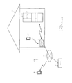
図1に示すように、実施形態のカメラ装置2(貯蔵庫用カメラ装置)は、室内撮像システム100における家電製品としての冷蔵庫(貯蔵庫)1の内部に配置される。
まず、前記室内撮像システム100について説明する。この室内撮像システム100は、冷蔵庫1内を撮像するための前記カメラ装置2、前記冷蔵庫1側との間で通信を行うためのアクセスポイント3、操作端末4等により構成されている。このうち、アクセスポイント3は、外部ネットワーク(広域通信網や携帯電話網)5に接続しており、外部ネットワーク5を介して遠隔地の操作端末4やサーバ6等と冷蔵庫1側との間を通信可能に接続している。本実施形態では、冷蔵庫1とアクセスポイント3との間、アクセスポイント3と操作端末4との間、及びカメラ装置2とアクセスポイント3との間は、近距離無線通信例えばBluetooth(登録商標)による無線通信にて通信が行われる。
Hereinafter, the first embodiment will be described with reference to FIGS.
As shown in FIG. 1, a camera device 2 (a storage camera device) according to an embodiment is disposed inside a refrigerator (storage) 1 as a home appliance in the indoor imaging system 100.
First, the indoor imaging system 100 will be described. The indoor imaging system 100 includes the camera device 2 for imaging the inside of the refrigerator 1, an access point 3 for performing communication with the refrigerator 1 side, an operation terminal 4, and the like. Among these, the access point 3 is connected to an external network (a wide-area communication network or a mobile phone network) 5, and is connected between the remote operation terminal 4, the server 6, and the like and the refrigerator 1 side via the external network 5. Connected so that communication is possible. In this embodiment, between the refrigerator 1 and the access point 3, between the access point 3 and the operation terminal 4, and between the camera device 2 and the access point 3 is based on short-range wireless communication, for example, Bluetooth (registered trademark). Communication is performed by wireless communication.

操作端末4は、カメラ装置2に室内を撮像させるための撮像指示を入力するものであり、タブレット型のパソコンや、いわゆるスマートフォン(高機能携帯電話)を想定している。この操作端末4は、住宅7内に位置している場合には、アクセスポイント3との間で近距離無線方式により通信可能に接続される。また、操作端末4は、住宅7外に位置している場合には、広域通信により外部ネットワーク5を介してアクセスポイント3との間で通信可能に接続される。また、操作端末4は、住宅7内からであっても広域通信により外部ネットワーク5を介してアクセスポイント3に接続することが可能であるとともに、住宅7内においては、アクセスポイント3を介さずに冷蔵庫1側と直接的に通信可能でもある。   The operation terminal 4 inputs an imaging instruction for causing the camera device 2 to image a room, and is assumed to be a tablet personal computer or a so-called smart phone (high-performance mobile phone). When the operation terminal 4 is located in the house 7, the operation terminal 4 is connected to the access point 3 so as to be communicable by a short-range wireless method. When the operation terminal 4 is located outside the house 7, the operation terminal 4 is communicably connected to the access point 3 via the external network 5 by wide area communication. In addition, the operation terminal 4 can be connected to the access point 3 via the external network 5 by wide area communication even from inside the house 7, and in the house 7 without using the access point 3. It is also possible to communicate directly with the refrigerator 1 side.

サーバ6は、周知のコンピュータシステムにより構成されており、冷蔵庫1にアクセスするための情報(例えばIPアドレス等)等を記憶しているとともに、本実施形態では、カメラ装置2により撮像された撮像データを記憶する。なお、図1では冷蔵庫1のみを図示しているが、図示しないエアコン等、他の家電製品もネットワーク化されている。   The server 6 is configured by a well-known computer system, stores information for accessing the refrigerator 1 (for example, an IP address) and the like, and in the present embodiment, image data captured by the camera device 2 Remember. Although only the refrigerator 1 is shown in FIG. 1, other home appliances such as an air conditioner (not shown) are also networked.

このように家電製品をネットワーク化することにより、各家電製品の消費電力をユーザに目に見える形で提供する見える化、夏場の昼間等の電力需要が大きくなる時間帯における電力消費を低減するピークシフト、一般家庭の定格を超えるような電力の瞬間的な使用を回避するピークカット等の電力コントロールや、家電製品の故障診断等、使い勝手や快適性あるいは利便性を提供するためのシステムを提供することが可能となる。また、カメラ装置2を例えば冷蔵室内に設置することにより、冷蔵庫1の室内の様子(物品の貯蔵状態等)を確認すること等も可能となる。そして、これら各種の情報や撮像データ等をサーバ6に記憶することで、遠隔地であっても外部ネットワーク5等を介して操作端末4等によりそれらの情報を参照することが可能となる。   Networking home appliances in this way makes it possible to visualize the power consumption of each home appliance in a form that is visible to the user, and peaks that reduce power consumption during times of day when power demand increases during the daytime in summer Providing systems that provide convenience, comfort, or convenience, such as power control such as peak cuts to avoid momentary use of power that exceeds shifts and general household ratings, and fault diagnosis of home appliances It becomes possible. Further, by installing the camera device 2 in, for example, a refrigerated room, it is possible to check the state of the refrigerator 1 (such as the storage state of articles). Then, by storing these various types of information, imaging data, and the like in the server 6, it is possible to refer to the information by the operation terminal 4 or the like via the external network 5 or the like even in a remote place.

次に、カメラ装置2について説明する。
このカメラ装置2は、図2〜図6に示すように、外殻としてケース200を有する。このケース200は、一面が開口する矩形箱状の本体ケース部(第1ケース部)201と、一面が開口する浅底な矩形箱状の蓋ケース部(第2ケース部)202とを有する。前記本体ケース部201及び蓋ケース部202は合成樹脂製(非金属製)である。このケース200は本体ケース部201の開口部と蓋ケース部202の開口部とをねじ200aにより接合して構成され、全体として直方体をなす。本体ケース部201の開口部端面にはパッキン溝201aが形成されており、このパッキン溝201aに防水部材としての枠状のパッキン203が嵌合されている。このパッキン203により本体ケース部201と蓋ケース部202とが水密に接合されている。上記パッキン203はシリコーンゴムから構成されている。
Next, the camera device 2 will be described.
As shown in FIGS. 2 to 6, the camera device 2 includes a case 200 as an outer shell. The case 200 includes a rectangular box-shaped main body case portion (first case portion) 201 having an opening on one surface, and a shallow rectangular box-shaped lid case portion (second case portion) 202 having an opening on one surface. The main body case portion 201 and the lid case portion 202 are made of synthetic resin (non-metallic). The case 200 is configured by joining the opening of the main body case 201 and the opening of the lid case 202 with a screw 200a, and forms a rectangular parallelepiped as a whole. A packing groove 201a is formed on the end surface of the opening of the main body case 201, and a frame-shaped packing 203 as a waterproof member is fitted into the packing groove 201a. The main body case portion 201 and the lid case portion 202 are joined in a watertight manner by the packing 203. The packing 203 is made of silicone rubber.

本体ケース部201においては開口部と反対側の面部(カメラ装置2としては正面であり、図3、図4において左となる面部)が一面部(撮像方向面部)201Iに相当する。この一面部201Iは平坦であり、この一面部201Iには、中央に円形の撮像用窓部201bが形成されている。さらにこの撮像用窓部201bを基準にして上下の等距離部位に撮像ライト用窓部201c、201cが形成されている。さらに、この一面部201Iには、照度センサ用窓部201dが形成されている。   In the main body case portion 201, a surface portion opposite to the opening portion (a front surface as the camera device 2 and a left surface portion in FIGS. 3 and 4) corresponds to one surface portion (imaging direction surface portion) 201I. The one surface portion 201I is flat, and a circular imaging window 201b is formed at the center of the one surface portion 201I. Further, imaging light window portions 201c and 201c are formed at equidistant portions above and below the imaging window portion 201b. Further, an illuminance sensor window portion 201d is formed on the one surface portion 201I.

この一面部201Iは、図7に示すように、当該一面部201I周縁部と前記撮像用窓部201b周縁部とが同一高さで若干突出している。
この一面部201Iには、これを覆うシート状のカバー部材204が図示しない両面テープにより接着されて装着されている。但し、このカバー部材204には前記撮像用窓部201bを覆わないための孔部204aが形成されており、つまり、このカバー部材204は撮像用窓部201bと対向する部位に当該撮像用窓部201bを外部に臨ませる孔部204aが形成されている以外は無孔状である。よって、前記撮像用窓部201bは覆われていない。このカバー部材204は透明な材料から構成されており、このカバー部材204において、接着される側の面に予め意匠印刷(図示せず)が施されている。この意匠印刷は、前記撮像ライト用窓部201c、201c、照度センサ用窓部201d部分には形成されておらず、透明部204b、204b、204cが形成されている。
As shown in FIG. 7, the one surface portion 201 </ b> I has the one surface portion 201 </ b> I peripheral portion and the imaging window portion 201 b peripheral portion slightly projecting at the same height.
On this one surface portion 201I, a sheet-like cover member 204 covering the same is attached with a double-sided tape (not shown). However, the cover member 204 is formed with a hole portion 204a for not covering the imaging window portion 201b. That is, the cover member 204 is located at a portion facing the imaging window portion 201b. It is non-porous except that a hole 204a that allows 201b to face the outside is formed. Therefore, the imaging window 201b is not covered. The cover member 204 is made of a transparent material, and design printing (not shown) is applied in advance to the surface of the cover member 204 to be bonded. This design printing is not formed in the imaging light window portions 201c and 201c and the illuminance sensor window portion 201d, but transparent portions 204b, 204b and 204c are formed.

又、本体ケース部201における上面部201Jにはスイッチ用孔部201e、201eが形成されている。上面部201Jはシート状のスイッチカバー205が例えば図示しない両面テープで接着されている。このスイッチカバー205によりスイッチ用孔部201e、201eが閉鎖されている。このスイッチカバー205において接着される側の面に予め意匠印刷205a、205bが施されている。但しこの意匠印刷205a、205b部分は前記スイッチ用孔部201e、201eに対応しており、この部分には両面テープは接着されていない。このスイッチカバー205は上記意匠印刷205a、205b部分で、スイッチ操作のために可撓変形可能となっている。   Further, switch holes 201e and 201e are formed in the upper surface portion 201J of the main body case portion 201. A sheet-like switch cover 205 is bonded to the upper surface portion 201J with a double-sided tape (not shown), for example. The switch holes 205e and 201e are closed by the switch cover 205. Design prints 205a and 205b are applied in advance to the surface of the switch cover 205 to be bonded. However, the design prints 205a and 205b correspond to the switch holes 201e and 201e, and the double-sided tape is not bonded to these portions. The switch cover 205 is designed to be flexibly deformed for switch operation at the design prints 205a and 205b.

又、本体ケース部201における右壁部201Mには、後述するが当該右壁部201M内面近傍に位置する前記リードスイッチ206cに対応して、図8に示すように、浅底で縦長な操作子用凹部201fが形成されている。この操作子用凹部201fには操作子配置用のスペースを形成するスライドカバー201gが係合により取り付けられている。このスライドカバー201gには長孔201hが形成されている。操作子用凹部201fとスライドカバー201gとの間のスペースには、操作子206aがこの場合上下方向にスライド可能に配置されている。この操作子206aには磁石206bが設けられている。又、この操作子206aに突設されたノブ206dは前記長孔201hに位置する。この操作子206aと磁石206bと後述するリードスイッチ206cとでスライドスイッチ206が構成されている。このスライドスイッチ206は電源をオンオフするための電源スイッチに相当する。このスライドスイッチ206は、操作子206aが下方向に操作されることによってリードスイッチ206cがオンする。つまりスライドスイッチ206がスイッチオンし、電源がオンする。なお、スライドカバー201gにおいて下部には「ON」の文字が付設され、又、上部には「OFF」の文字が付設されている。   Further, as shown in FIG. 8, the right wall 201M of the main body case 201 corresponds to the reed switch 206c located near the inner surface of the right wall 201M. A concave portion 201f is formed. A slide cover 201g that forms a space for arranging the operation element is attached to the operation element recess 201f by engagement. A long hole 201h is formed in the slide cover 201g. In this case, an operating element 206a is slidably disposed in the space between the operating element recess 201f and the slide cover 201g. The operation element 206a is provided with a magnet 206b. A knob 206d protruding from the operating element 206a is located in the long hole 201h. The operation switch 206a, the magnet 206b, and a reed switch 206c described later constitute a slide switch 206. The slide switch 206 corresponds to a power switch for turning on / off the power. In the slide switch 206, the reed switch 206c is turned on when the operation element 206a is operated downward. That is, the slide switch 206 is switched on and the power is turned on. In the slide cover 201g, a character “ON” is attached to the lower part, and a character “OFF” is attached to the upper part.

一方、前記蓋ケース部202の下部には、電池収容部207が本体ケース部201方向へ突出形成されている。この電池収容部207には、電池出し入れ用の開口部207aを一端部(後端部)に有する。この開口部207aから電池208が挿入配置されている。この電池208はリチウム電池であり、又一次電池である。電池収容部207の前記開口部207aは、電池蓋(蓋)209によって開閉可能に閉塞される。この電池蓋209は、下縁部が前記外側開口部の下部に係合され、上部がねじ209aによって前記開口部207a縁部の上部にねじ止めされる。   On the other hand, a battery housing part 207 is formed in the lower part of the lid case part 202 so as to protrude toward the main body case part 201. The battery housing portion 207 has an opening 207a for inserting and removing the battery at one end (rear end). A battery 208 is inserted from the opening 207a. The battery 208 is a lithium battery or a primary battery. The opening 207a of the battery housing portion 207 is closed by a battery lid (lid) 209 so as to be opened and closed. The battery lid 209 has a lower edge engaged with the lower portion of the outer opening, and an upper portion screwed to the upper portion of the edge of the opening 207a by a screw 209a.

前記電池208はカメラ装置2の電源である。このため、カメラ装置2は、電源ケーブル等が不要となり、冷蔵庫1内の任意の場所に設置することが可能となる。又、前記電池収容部207の開口部207aと前記電池蓋209との間には防水手段としてのシリコーンゴムからなるパッキン210が介在されている。前記ケース200の内部には、前記電池208の上方に位置して、撮像手段としての撮像部211、基板212、通信手段としての通信モジュール213が収容配置されている。   The battery 208 is a power source for the camera device 2. For this reason, the camera device 2 does not require a power cable or the like, and can be installed at any place in the refrigerator 1. Further, a packing 210 made of silicone rubber as a waterproof means is interposed between the opening 207a of the battery housing 207 and the battery lid 209. Inside the case 200, an imaging unit 211 serving as an imaging unit, a substrate 212, and a communication module 213 serving as a communication unit are accommodated and disposed above the battery 208.

前記撮像部211は、外殻としてのレンズホルダ211aと、レンズとしての外側レンズ211bと、レンズ組み立て211cと、撮像素子211dと、撮像基板211eとを備える。前記外側レンズ211bとレンズ組み立て211cは広角レンズを含んで構成されている。当該広角レンズは概ね120度程度の視野角を有する。比較例として一般的なWebカメラの場合、その視野角は概ね55度程度である。   The imaging unit 211 includes a lens holder 211a as an outer shell, an outer lens 211b as a lens, a lens assembly 211c, an imaging element 211d, and an imaging substrate 211e. The outer lens 211b and the lens assembly 211c are configured to include a wide-angle lens. The wide-angle lens has a viewing angle of about 120 degrees. In the case of a general Web camera as a comparative example, the viewing angle is approximately 55 degrees.

レンズホルダ211aは外形が円形状をなしており、このレンズホルダ211aに外側レンズ211bとレンズ組み立て211cとが保持されている。前記撮像素子211dはCCDやCMOSから構成されており、前記撮像基板211eに実装されている。この撮像基板211eはレンズホルダ211aの後端部(図4でいうと右側の端部)に取り付けられている。   The lens holder 211a has a circular outer shape, and the lens holder 211a holds an outer lens 211b and a lens assembly 211c. The image pickup device 211d is composed of a CCD or a CMOS, and is mounted on the image pickup substrate 211e. The imaging substrate 211e is attached to the rear end (the right end in FIG. 4) of the lens holder 211a.

前記レンズホルダ211aは前記撮像用窓部201bに嵌合されている。この嵌合部には防水手段としてのOリング211fが介在されている。前記撮像部211の最外面(外側レンズ211bの最外面)は、図4に示すように、ケース200における一面部201Iの最外面(撮像用窓部201bの周縁部外面)より凹んだ位置にある。又、前記撮像基板211eにはフレキシブルケーブル211gの一端部を接続する接続端子211hが実装されている。このフレキシブルケーブル211gは撮像基板211eと後述の主基板212Aとを接続している。   The lens holder 211a is fitted in the imaging window 201b. An O-ring 211f as a waterproof means is interposed in the fitting portion. As shown in FIG. 4, the outermost surface of the imaging unit 211 (outermost surface of the outer lens 211b) is in a position recessed from the outermost surface of the one surface portion 201I of the case 200 (outer peripheral surface of the imaging window portion 201b). . A connection terminal 211h for connecting one end of the flexible cable 211g is mounted on the imaging substrate 211e. The flexible cable 211g connects the imaging board 211e and a main board 212A described later.

前記基板212は主基板212Aと補助基板212Bとを有して構成されている。補助基板212Bには、前記撮像部211を逃げるための孔部212Baが形成されている。そして、この補助基板212Bは、ケース200における前記一面部201Iの裏側にリブを介して当該一面部201I内面と離間状態に取り付けられている。この場合、撮像基板211e及びフレキシブルケーブル211gはこの補助基板212Bよりも後方に位置する。   The substrate 212 includes a main substrate 212A and an auxiliary substrate 212B. A hole 212Ba for escaping the imaging unit 211 is formed in the auxiliary substrate 212B. And this auxiliary board | substrate 212B is attached to the back side of the said one surface part 201I in the case 200 in the spaced-apart state from the said one surface part 201I through the rib. In this case, the imaging board 211e and the flexible cable 211g are located behind the auxiliary board 212B.

前記補助基板212Bの後面下部には電池接続端子212Bb、212Bbが設けられており、この電池接続端子212Bb、212Bbに前記電池208のプラス端子及びマイナス端子が接続される。前記補助基板212Bの前面部には、図4及び図9に示すように、撮像用照明手段に相当する撮像ライト214、214が実装されていると共に、照度センサ215が実装されている。前記撮像ライト214、214は前記補助基板212Bの取付状態において、前記撮像ライト用窓部201c、201cと対向又は嵌入する。又、照度センサ215は照度センサ用窓部201dと対向する。   Battery connection terminals 212Bb and 212Bb are provided at the lower part of the rear surface of the auxiliary substrate 212B, and a positive terminal and a negative terminal of the battery 208 are connected to the battery connection terminals 212Bb and 212Bb. As shown in FIGS. 4 and 9, imaging lights 214 and 214 corresponding to imaging illumination means are mounted on the front surface of the auxiliary substrate 212B, and an illuminance sensor 215 is mounted. The imaging lights 214 and 214 face or fit into the imaging light windows 201c and 201c in the attached state of the auxiliary board 212B. The illuminance sensor 215 faces the illuminance sensor window 201d.

さらに前記補助基板212Bの後面の端部にはリードスイッチ206cが実装されており、このリードスイッチ206cは、図8に示すように、一壁部としての右壁部201Mの内面近傍に位置する。リードスイッチ206cと操作子206aとが前記右壁部201Mの操作子用凹部201fの壁部で離隔される構成を防水手段としている。   Further, a reed switch 206c is mounted on the end portion of the rear surface of the auxiliary board 212B, and the reed switch 206c is located near the inner surface of the right wall portion 201M as one wall portion as shown in FIG. The structure in which the reed switch 206c and the operation element 206a are separated by the wall part of the operation part recess 201f of the right wall part 201M is waterproof means.

さらに主基板212A及び補助基板212Bには、複数の電子部品を電気的に接続するための金属製の回路パターン(図示せず)が形成されている。又、この補助基板212Bの前面には、図9に示すように、そのほぼ全面に金属製の回路パターンであるグランド用パターン212Bcが形成されている。このグランドパターン212Bcはケース200外部からのノイズ遮蔽用の電気的シールドとして作用する。   Further, a metal circuit pattern (not shown) for electrically connecting a plurality of electronic components is formed on the main board 212A and the auxiliary board 212B. Further, as shown in FIG. 9, a ground pattern 212Bc, which is a metal circuit pattern, is formed on the entire front surface of the auxiliary substrate 212B. The ground pattern 212Bc acts as an electrical shield for shielding noise from the outside of the case 200.

又、この補助基板212Bにはフレキシブルケーブル212Bdを接続するための接続端子212Beが実装されている。このフレキシブルケーブル212Bdは補助基板212Bと主基板212Aとを接続している。   In addition, a connection terminal 212Be for connecting the flexible cable 212Bd is mounted on the auxiliary board 212B. The flexible cable 212Bd connects the auxiliary board 212B and the main board 212A.

前記主基板212Aは、前記補助基板212Bの後方部に位置してねじ止めにより本体ケース部201に取り付けられている。この主基板212Aにはこのカメラ装置2の主たる制御を行うためのカメラ側制御部220(後述する)としてのマイクロコンピュータなどを実装している。さらに、この主基板212Aの上部には、スイッチとして、設定開始や設定確定あるいは設定終了などのための設定スイッチ216、各種モードを指定あるいは選択するためのモードスイッチ217を実装している。   The main board 212A is located behind the auxiliary board 212B and is attached to the main body case 201 by screwing. On the main board 212A, a microcomputer or the like is mounted as a camera-side control unit 220 (described later) for performing main control of the camera device 2. Further, a setting switch 216 for setting start, setting confirmation, or setting end and a mode switch 217 for designating or selecting various modes are mounted on the main board 212A as switches.

この設定スイッチ216、モードスイッチ217はタクトスイッチ(プッシュスイッチ)から構成されており、夫々、操作子216a、217aを有する。各スイッチ216、217は各操作子216a、217aが上から下へ押圧操作されることによりスイッチ動作し、操作後は元状態に戻る。さらに各操作子216a、217aは、図4に示すように、前記各スイッチ用孔部201e、201e内に配置されており、前記スイッチカバー205の意匠印刷205a、205b部分が押圧されると、当該部分が可撓変形して前記各操作子216a、217aが押圧操作される。この意匠印刷205a、205bの部分は、前記設定スイッチ216、モードスイッチ217の操作部216b、217bとして機能する(設定スイッチ216、モードスイッチ217の一部を構成する)。   The setting switch 216 and the mode switch 217 are constituted by tact switches (push switches) and have operation elements 216a and 217a, respectively. The switches 216 and 217 are switched by pressing the operation elements 216a and 217a from top to bottom, and return to the original state after the operation. Further, as shown in FIG. 4, the operation elements 216a and 217a are arranged in the respective switch hole portions 201e and 201e, and when the design prints 205a and 205b of the switch cover 205 are pressed, The portions are flexibly deformed, and the operation elements 216a and 217a are pressed. The design printing portions 205a and 205b function as the operation units 216b and 217b of the setting switch 216 and the mode switch 217 (part of the setting switch 216 and the mode switch 217).

さらに、この主基板212Aには加速度センサ218、温度センサ219(図10参照)が実装されている。加速度センサ218は、カメラ装置2の設置姿勢(縦置き、横置き、一面部201Iを下向き、一面部201Iを上向き)を検出する。温度センサ219は、カメラ装置2が設置された場所の温度を検知する。カメラ装置2では、この温度センサ219による検知温度が冷蔵室温度帯の場合には冷蔵室にカメラ装置2が設置されたと判断し、前記検知温度が冷凍室温度帯の場合には冷凍室にカメラ装置2が設置されたと判断する。この場合、冷凍室に設置されていると判断した場合、故障等の虞が懸念されるため、冷蔵庫1側にその旨を送信して冷蔵庫1の操作パネル22等にてユーザーに報知する。   Further, an acceleration sensor 218 and a temperature sensor 219 (see FIG. 10) are mounted on the main board 212A. The acceleration sensor 218 detects the installation posture of the camera device 2 (vertical placement, lateral placement, the one surface portion 201I faces downward, and the one surface portion 201I faces upward). The temperature sensor 219 detects the temperature of the place where the camera device 2 is installed. The camera device 2 determines that the camera device 2 is installed in the refrigerator compartment when the temperature detected by the temperature sensor 219 is in the refrigerator compartment temperature zone. If the detected temperature is in the refrigerator compartment temperature zone, the camera device 2 It is determined that the device 2 has been installed. In this case, if it is determined that it is installed in the freezer compartment, there is a risk of failure or the like, so that information is transmitted to the refrigerator 1 side and notified to the user via the operation panel 22 of the refrigerator 1 or the like.

さらにこの主基板212Aには、フレキシブルケーブル212Aaを接続するための接続端子212Abが実装されている。このフレキシブルケーブル212Aaは、主基板212Aと通信モジュール213とを接続している。前記通信モジュール213は、前記ケース200の内部に、基板212より後方の位置で前記本体ケース部201にねじ止めにより取り付けられている。この通信モジュール213は、モジュールケース213aの内部に、通信制御のための回路を実装したモジュール基板213bなどを有して構成されている。又、このモジュール基板213bにはアンテナ213cがパターンにより形成されている。このアンテナ213cはケース200において前記一面部201Iと反対側の面部である他面部202Tの側に設けられている。   Further, a connection terminal 212Ab for connecting the flexible cable 212Aa is mounted on the main board 212A. The flexible cable 212Aa connects the main board 212A and the communication module 213. The communication module 213 is attached inside the case 200 to the main body case 201 at a position behind the substrate 212 by screws. The communication module 213 includes a module substrate 213b on which a circuit for communication control is mounted and the like inside the module case 213a. An antenna 213c is formed in a pattern on the module substrate 213b. This antenna 213c is provided on the side of the other surface portion 202T which is the surface portion opposite to the one surface portion 201I in the case 200.

通信モジュール213は、撮像部211で撮像した庫内の撮像データを、アクセスポイント3を介して操作端末4やサーバ6等に送信する。なお、サーバ6に送信するのは、撮像データをサーバ6に記憶させるためである。ここで、撮像データとは、室内の画像を含むデータであり、例えばビットマップ形式やJPEG形式あるいはMPEG形式などの周知のフォーマットのデータ(静止画、動画)、そのデータを圧縮や暗号化あるいは画像処理することにより変換したデータ等、冷蔵庫1内の様子を操作端末4等で確認できるデータであれば、どのような形式のものであってもよい。   The communication module 213 transmits the image data in the warehouse imaged by the imaging unit 211 to the operation terminal 4, the server 6, and the like via the access point 3. The transmission to the server 6 is to store the imaging data in the server 6. Here, the imaging data is data including indoor images. For example, data in a known format (still image, moving image) such as bitmap format, JPEG format, or MPEG format, and the data is compressed, encrypted, or imaged. Any type of data may be used as long as it can be confirmed by the operation terminal 4 or the like, such as data converted by processing.

前記カメラ装置2において、撮像部211と、基板212と、通信モジュール213と、電池208はケース200によりユニット(一体物)2Aとして構成されている。そして、電池208は通信モジュール213を覆わない位置に設けられている。つまり、通信モジュール213が有するアンテナ213cの良好な送受信方向(矢印A方向)を覆わない位置に設けられている。   In the camera device 2, the imaging unit 211, the substrate 212, the communication module 213, and the battery 208 are configured as a unit (integral object) 2 </ b> A by the case 200. The battery 208 is provided at a position that does not cover the communication module 213. That is, the antenna 213c included in the communication module 213 is provided at a position that does not cover the favorable transmission / reception direction (arrow A direction).

前記通信モジュール213のアンテナ213cと前記基板212との距離H1(図4参照)は、無線電波の波長λの1/2以下の寸法例えば10mmに設定されている。この場合、無線電波の周波数を2.5GHz体とすると、波長λが約120mmであり、当該波長λの1/2(60mm)以下の寸法に設定されている。   The distance H1 (see FIG. 4) between the antenna 213c of the communication module 213 and the substrate 212 (see FIG. 4) is set to a dimension that is 1/2 or less of the wavelength λ of the radio wave, for example, 10 mm. In this case, when the frequency of the radio wave is 2.5 GHz, the wavelength λ is about 120 mm, and the dimension is set to 1/2 (60 mm) or less of the wavelength λ.

ここで、カメラ装置2においては、図4に示すように、質量が大きい電池208がケース200の下部に位置することから、ケース200の中心(体積中心)Cに対してカメラ装置2の重心Gが異なる位置、この場合下方に存在する。
又、前記ケース200において前記電池208と反対側の外面である上壁部201Jの外面には、前記設定スイッチ216、モードスイッチ217の一部である操作部216b、217b(防止手段)が存在する。
Here, in the camera device 2, as shown in FIG. 4, since the battery 208 having a large mass is located below the case 200, the center of gravity G of the camera device 2 with respect to the center (volume center) C of the case 200. Are in different positions, in this case below.
Further, on the outer surface of the upper wall 201J, which is the outer surface opposite to the battery 208 in the case 200, there are operation units 216b and 217b (prevention means) which are part of the setting switch 216 and mode switch 217. .

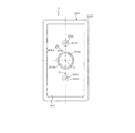
前記カメラ装置2の電気的構成について図10を参照して説明する。カメラ側制御部220は、前記主基板212Aが有する既述のマイクロコンピュータにより構成されている。このカメラ側制御部220は、CPU220a、ROM220b、RAM220c及び時計部220d、情報記憶手段としての不揮発性メモリ220e等を有し、カメラ装置2全体を制御する。具体的には、カメラ側制御部220は、撮像部211による撮像タイミングの制御、撮像する際の撮像環境を整える制御(撮像ライト214の点灯制御)、通信モジュール213による撮像データの送信、照度センサ215による後述する撮像指示の受信(受け付け)等のための制御等を行っている。また、カメラ側制御部220は、本実施形態では、撮像した画像の補正等を行う画像処理も行っている。   The electrical configuration of the camera device 2 will be described with reference to FIG. The camera-side control unit 220 is configured by the microcomputer already described in the main board 212A. The camera-side control unit 220 includes a CPU 220a, a ROM 220b, a RAM 220c, a clock unit 220d, a nonvolatile memory 220e as information storage means, and the like, and controls the entire camera device 2. Specifically, the camera-side control unit 220 controls imaging timing by the imaging unit 211, control for adjusting an imaging environment when imaging (lighting control of the imaging light 214), transmission of imaging data by the communication module 213, illuminance sensor Control for receiving (accepting) an imaging instruction, which will be described later, by 215 is performed. In the present embodiment, the camera-side control unit 220 also performs image processing for correcting a captured image.

前記時計部220dは、リアルタイムクロックモジュールから構成されており、時刻・カレンダー機能を有し、リアルタイムの時間(時刻、月日、曜日)を計測できる。
カメラ側制御部220に接続されている照度センサ215は、いわゆる照度センサであり、カメラ装置2の周辺の照度を検出する。より詳細には、照度センサ215は、所定の波長帯域の光エネルギー(本実施形態では、後述する室内照明灯130、132から発せられる光エネルギー)を検出する。照度センサ215で検出された光エネルギーは、電気信号に変換されてカメラ側制御部220に出力される。
The clock unit 220d is composed of a real-time clock module, has a time / calendar function, and can measure a real-time time (time, month, day of the week).
The illuminance sensor 215 connected to the camera-side control unit 220 is a so-called illuminance sensor, and detects the illuminance around the camera device 2. More specifically, the illuminance sensor 215 detects light energy in a predetermined wavelength band (in this embodiment, light energy emitted from indoor lighting lamps 130 and 132 described later). The light energy detected by the illuminance sensor 215 is converted into an electric signal and output to the camera side controller 220.

本実施形態の場合、ユーザからの撮像指示の最終的な信号形態は、所定のパターンで発せられた光エネルギー(後述の室内照明灯130、132の所定パターンの点滅)により示される構成となっており、カメラ側制御部220は、照度センサ215により上記所定パターンの点滅を検出したときに、撮像指示であると判断する。   In the case of the present embodiment, the final signal form of the imaging instruction from the user has a configuration indicated by light energy emitted in a predetermined pattern (flashing of a predetermined pattern of indoor illumination lights 130 and 132 described later). The camera-side control unit 220 determines that it is an imaging instruction when the illuminance sensor 215 detects blinking of the predetermined pattern.

このような構成のカメラ装置2は、スライドスイッチ206がオンされた状態(電源オン状態)で使用され、常には通常動作モードよりも相対的に消費電力が少ない低電力モード(スリープ制御モード)にて待機しており、撮像指示を受信すると、通常動作モードに復帰して庫内を撮像する。   The camera device 2 having such a configuration is used in a state where the slide switch 206 is turned on (power-on state), and is always in a low power mode (sleep control mode) that consumes relatively less power than the normal operation mode. When the imaging instruction is received, the normal operation mode is restored and the interior is imaged.

一方、前記カメラ装置2が設置される冷蔵庫1は、図11に示すように、本体102の上部から順に、食材を貯蔵するための貯蔵庫である冷蔵室103、野菜室104、製氷室105、上部冷凍室106、及び下部冷凍室107が設けられている。冷蔵室103及び野菜室104と、製氷室105及び上部冷凍室106との間は、図示しない断熱仕切壁により仕切られている。冷蔵室103は、ヒンジ102a、102bによって回転可能に支持されたいわゆる両開き式(回転式)の左扉103a及び右扉103bによって開閉される。   On the other hand, as shown in FIG. 11, the refrigerator 1 in which the camera device 2 is installed has a refrigerator room 103, a vegetable room 104, an ice making room 105, an upper part, which are storages for storing ingredients, in order from the upper part of the main body 102. A freezer compartment 106 and a lower freezer compartment 107 are provided. The refrigerator compartment 103 and the vegetable compartment 104 and the ice making compartment 105 and the upper freezer compartment 106 are partitioned by a heat insulating partition wall (not shown). The refrigerator compartment 103 is opened and closed by a so-called double-open (rotary) left door 103a and right door 103b that are rotatably supported by hinges 102a and 102b.

野菜室104、製氷室105、上部冷凍室106及び下部冷凍室107は、引き出し式の扉104a、扉105a、扉106a及び扉107aによってそれぞれ開閉されるようになっている。この場合右扉103bの長さ(ヒンジ102bの回転中心から開放端までの長さ)が左扉103aの長さより長く形成されている。
各扉には、その開閉状態を検知するための扉センサ124(図10参照)が設けられている。なお、図11に示す冷蔵庫1の構成は一例であり、各貯蔵庫の配置順が異なっていたり、例えば上部冷凍室106が冷蔵と冷凍とを切り替え可能な切替室であるような構成でもよい。
The vegetable compartment 104, the ice making compartment 105, the upper freezer compartment 106 and the lower freezer compartment 107 are opened and closed by a pull-out door 104a, a door 105a, a door 106a and a door 107a, respectively. In this case, the length of the right door 103b (the length from the rotation center of the hinge 102b to the open end) is longer than the length of the left door 103a.
Each door is provided with a door sensor 124 (see FIG. 10) for detecting the open / closed state. Note that the configuration of the refrigerator 1 shown in FIG. 11 is an example, and the arrangement order of the storages may be different, or the upper freezing chamber 106 may be a switching chamber that can be switched between refrigeration and freezing, for example.

冷蔵室103の左扉103aには、上段から順にドアポケット108a、ドアポケット109a、ドアポケット110aが設けられており、右扉103bには、上段から順にドアポケット108b、ドアポケット109b、ドアポケット110bが設けられている。また、冷蔵室103内には、例えばガラス等の透明性材料で形成されている複数の棚板111が設けられているとともに、最下段には、例えば卵室やチルド室のような特定目的室112が配置されている。また、冷蔵室103の内部には照明手段としての室内照明灯130、132(図10参照)が設けられている。室内照明灯130は天井に設けられ、室内照明灯132は図11では図示しないが側面に設けられている。このうち、室内照明灯130は庫内の上部側、室内照明灯132は庫内の中央部や下部等、庫内の特定の位置を照らすために設けられている。   The left door 103a of the refrigerator compartment 103 is provided with a door pocket 108a, a door pocket 109a, and a door pocket 110a in order from the top, and the right door 103b has a door pocket 108b, a door pocket 109b, and a door pocket 110b in order from the top. Is provided. In addition, a plurality of shelves 111 made of a transparent material such as glass are provided in the refrigerating room 103, and a special purpose room such as an egg room or a chilled room is provided at the lowest level. 112 is arranged. Further, inside the refrigerating room 103, room illumination lights 130 and 132 (see FIG. 10) are provided as illumination means. The interior illumination lamp 130 is provided on the ceiling, and the interior illumination lamp 132 is provided on the side surface although not shown in FIG. Among these, the indoor illumination lamp 130 is provided to illuminate a specific position in the warehouse, such as the upper side in the warehouse, and the indoor illumination lamp 132, such as a central portion or a lower portion in the warehouse.

冷蔵室103の左扉103a及び右扉103bは、大きさは異なるが、材料的にはほぼ同じ構成である。右扉103bを代表して、構成を説明する。右扉103bは、図12に示すように、その前面が絶縁性のガラス材料で形成されたガラス板103b1で構成され、後面(内面)が非金属の樹脂製の内板114及び縦板115(図11参照)で構成されている。そして、その内部には断熱材であるウレタン103b2が充填剤として充填されている。つまり、左扉103a及び右扉103bの前面側は、電波を透過させる非金属製材料であるガラス板103b1により構成されている。上記したドアポケット108a〜110a、108b〜110bは、この内板114に設けられている。また、左扉103aには、図11及び図13に示すように、右扉103bとの隙間Sを埋めるための回動式の非金属材料例えば合成樹脂である縦仕切り117が設けられている。なお、野菜室104の扉104a等も、右扉103bと同様にその前面がガラス板で覆われており、内部にはウレタンが断熱材として充填されている構成となっている。   Although the left door 103a and the right door 103b of the refrigerator compartment 103 are different in size, they are substantially the same in terms of material. The configuration will be described on behalf of the right door 103b. As shown in FIG. 12, the right door 103b is configured by a glass plate 103b1 having a front surface made of an insulating glass material, and a rear surface (inner surface) made of a nonmetallic resin inner plate 114 and a vertical plate 115 ( 11). And the inside is filled with urethane 103b2 which is a heat insulating material as a filler. That is, the front side of the left door 103a and the right door 103b is configured by the glass plate 103b1 that is a non-metallic material that transmits radio waves. The door pockets 108a to 110a and 108b to 110b described above are provided on the inner plate 114. Further, as shown in FIGS. 11 and 13, the left door 103a is provided with a vertical partition 117 made of a rotating non-metallic material such as synthetic resin for filling the gap S with the right door 103b. Note that the front of the door 104a and the like of the vegetable compartment 104 is covered with a glass plate in the same manner as the right door 103b, and the inside is filled with urethane as a heat insulating material.

前記野菜室104内には、図14に示すように、上下二つの野菜容器104b、104cを備えている。上側の野菜容器104bは透明な材料(合成樹脂など)によって構成されている。なお、下側の野菜容器104cも透明な材料で構成しても良い。
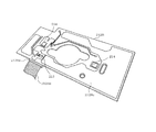
右扉103bにおいて上下の中央に位置する中段のドアポケット109bには、図12に示すように、前記カメラ装置2がホルダケース150を介して取り付けられている(配置される)。このカメラ装置2は、図11及び図13に示すように、右扉103bの開放端側に設けられている。カメラ装置2はその撮像部211が庫内を向く(一面部201Iが庫内を向く)ように配置されている。カメラ装置2が右扉103bに配置された状態では、スライドスイッチ206がオンされて電源オンとなっている(使用状態となっている)。
In the vegetable compartment 104, as shown in FIG. 14, two upper and lower vegetable containers 104b and 104c are provided. The upper vegetable container 104b is made of a transparent material (such as synthetic resin). The lower vegetable container 104c may also be made of a transparent material.
As shown in FIG. 12, the camera device 2 is attached (arranged) via a holder case 150 to a middle door pocket 109b located at the upper and lower centers of the right door 103b. As shown in FIGS. 11 and 13, the camera device 2 is provided on the open end side of the right door 103b. The camera device 2 is arranged so that the imaging unit 211 faces the interior (the one surface portion 201I faces the interior). In a state where the camera device 2 is disposed on the right door 103b, the slide switch 206 is turned on and the power is turned on (in use).

この場合、右扉103bの長さが左扉103aの長さより長く形成されているため、このカメラ装置2は図15に示すように冷蔵室103の上下左右のほぼ中央に位置している。特に、このカメラ装置2は、右扉103aのうちヒンジ102b側の端から、左扉103aの長さよりも長い当該右扉103a開放端側に位置している。右扉103bが閉鎖された状態において、カメラ装置2の撮像部211の撮像範囲は、撮像部211が扉103a、103bからなる扉の中央に位置した状態で、冷蔵室103の左右方向の奥行きの隅(図11に示すポイントP1、P2)、又は上下方向の奥行きの隅(図11に示すポイントP3、P4)を含む範囲である。なお、図16には、カメラ装置2で撮像した画像の一例を示している。又、撮像範囲としては、図11に示すポイントP11〜P18を含むようにしても良い。   In this case, since the length of the right door 103b is formed longer than the length of the left door 103a, the camera device 2 is positioned substantially at the center of the top, bottom, left, and right of the refrigerator compartment 103 as shown in FIG. In particular, the camera device 2 is located on the open end side of the right door 103a which is longer than the length of the left door 103a from the end on the hinge 102b side of the right door 103a. In a state where the right door 103b is closed, the imaging range of the imaging unit 211 of the camera device 2 is the depth of the refrigerator compartment 103 in the left-right direction with the imaging unit 211 positioned at the center of the door consisting of the doors 103a and 103b. This range includes corners (points P1 and P2 shown in FIG. 11) or vertical depth corners (points P3 and P4 shown in FIG. 11). FIG. 16 shows an example of an image captured by the camera device 2. Further, the imaging range may include points P11 to P18 shown in FIG.

前記ホルダケース150は右扉103bに配置されており、図12、図17及び図18に示すように、おおむね上部開放形の箱状をなす。当該ホルダケース150の庫内側の壁部150aの高さ寸法Hhは、前記カメラ装置2のケース200の高さの半分よりも長く構成されている。   The holder case 150 is disposed on the right door 103b, and generally has a box shape with an open top as shown in FIGS. A height dimension Hh of the inner wall 150a of the holder case 150 is configured to be longer than half of the height of the case 200 of the camera device 2.

カメラ装置2(ユニット2A)は、図12の配置状態において、撮像部211が貯蔵庫内である冷蔵室103内に向けて配置されている。又、基板212は撮像部211より冷蔵庫1外側に配置され、且つ通信手段である通信モジュール213は前記基板212より冷蔵庫1外側に配置されている。   In the arrangement state of FIG. 12, the camera device 2 (unit 2 </ b> A) is arranged with the imaging unit 211 facing the refrigerator compartment 103 that is a storage. The substrate 212 is disposed outside the refrigerator 1 from the imaging unit 211, and the communication module 213 serving as a communication unit is disposed outside the refrigerator 1 from the substrate 212.

又、この場合、右扉103bには、通信モジュール213と対向する位置には、金属部材(補強用金属部品や、金属蒸着を用いた真空断熱パネル)が無い構成となっている。
この図12において、カメラ装置2は、冷蔵庫1が有する扉(右扉103b)から冷蔵庫1内を撮像可能に取り付けられている。又、前記電池208は、通信モジュール213と前記右扉103bとの間の部分Eとは、異なる位置にある。
Further, in this case, the right door 103b has a configuration without a metal member (a reinforcing metal part or a vacuum heat insulating panel using metal vapor deposition) at a position facing the communication module 213.
In FIG. 12, the camera apparatus 2 is attached so that the inside of the refrigerator 1 can be imaged from the door (right door 103b) which the refrigerator 1 has. The battery 208 is located at a different position from the portion E between the communication module 213 and the right door 103b.

前記冷蔵庫1は、図10に示す庫側制御部121を有している。この庫側制御部121は、CPU121a、ROM121b、RAM121c、タイマ121d等を有するマイクロコンピュータで構成されており、冷蔵庫1全体を制御する。具体的には、庫側制御部121は、例えば操作パネル122から設定された運転状態となるように、温度センサ123で検出した庫内の温度や扉センサ124で検出した扉の開閉状態等に基づいて、周知の冷凍サイクルを構成する冷蔵用冷却機構125や冷凍用冷却機構126の運転状態を制御する。   The refrigerator 1 has a warehouse control unit 121 shown in FIG. The warehouse-side control unit 121 includes a microcomputer having a CPU 121a, a ROM 121b, a RAM 121c, a timer 121d, and the like, and controls the entire refrigerator 1. Specifically, the storage-side control unit 121 changes the temperature in the storage detected by the temperature sensor 123, the open / closed state of the door detected by the door sensor 124, etc. so that the operation state set from the operation panel 122, for example. Based on this, the operating states of the refrigeration cooling mechanism 125 and the refrigeration cooling mechanism 126 constituting a known refrigeration cycle are controlled.

操作パネル122には、パネル表示器127、パネルLED128、パネルブザー129が設けられている。パネル表示器127は、設定値等を表示する。パネルLED128は、操作スイッチや運転状態等を点灯させるために設けられている。パネルブザー129は、圧電ブザー等で構成され、操作に応じて音声(音エネルギー)を発することで、操作内容を報知する。又、操作パネル122は、通信の阻害の可能性があるため、通信部たる通信モジュール213と対向しない位置に設けると良い。例えば操作パネル122は、通信モジュール213が存在する扉には設けず、通信モジュール213が存在しない扉に設けると良い。   The operation panel 122 is provided with a panel display 127, a panel LED 128, and a panel buzzer 129. The panel display 127 displays setting values and the like. The panel LED 128 is provided to light up an operation switch, an operation state, and the like. The panel buzzer 129 is composed of a piezoelectric buzzer or the like, and notifies the operation content by emitting sound (sound energy) in response to the operation. Further, the operation panel 122 may be provided at a position that does not face the communication module 213 that is a communication unit because there is a possibility of hindering communication. For example, the operation panel 122 is preferably not provided on a door where the communication module 213 exists, but provided on a door where the communication module 213 does not exist.

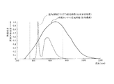
室内照明灯130、132は、LEDから構成され、扉が開放された際に点灯する。この室内照明灯130、132は、信号出力部も兼用しており、庫側制御部121からの制御により所定パターンで点滅可能となっている。この所定パターンの点滅は対カメラ装置2用の撮像指令を示す信号である。この所定パターンの点滅による撮像指令は前記照度センサ215により受信(受光)される。この場合、照度センサ215の受光特性は室内照明灯130、132のLED発光特性と相対的にほぼ同じに設定している。図19に示す波長領域λαの間でほぼ同じとなる領域を採用している。   The interior illumination lights 130 and 132 are composed of LEDs, and are lit when the door is opened. The indoor lighting lamps 130 and 132 also serve as a signal output unit, and can be blinked in a predetermined pattern under the control of the warehouse control unit 121. This blinking of the predetermined pattern is a signal indicating an imaging command for the camera device 2. The imaging command by the blinking of the predetermined pattern is received (received) by the illuminance sensor 215. In this case, the light reception characteristic of the illuminance sensor 215 is set to be substantially the same as the LED light emission characteristic of the room illumination lamps 130 and 132. A region that is substantially the same between the wavelength regions λα shown in FIG. 19 is employed.

送風機131は、通常の動作においては冷蔵庫1内の冷気を循環させるために設けられている。
通信アダプタ134は、アクセスポイント3や室内の操作端末4等との間で通信を行うものであり、本実施形態では、冷蔵庫1に着脱可能に設けられている。なお、図1には冷蔵庫1だけを図示しているが、通信アダプタ134は、エアコン等の他の家電製品にも設けられ、家電製品をネットワーク化している。また、通信アダプタ134は、アクセスポイント3を介すること無く、カメラ装置2との間で直接的に通信を行うことも可能な構成となっている。この通信アダプタ134は、上記したように見える化等にも用いられていることから、冷蔵庫1が動作している状態では基本的に常時作動している。
The blower 131 is provided to circulate cool air in the refrigerator 1 in a normal operation.
The communication adapter 134 communicates with the access point 3, the indoor operation terminal 4, and the like, and is detachably provided in the refrigerator 1 in this embodiment. Although only the refrigerator 1 is illustrated in FIG. 1, the communication adapter 134 is also provided in other home appliances such as an air conditioner to network home appliances. In addition, the communication adapter 134 is configured to be able to directly communicate with the camera device 2 without going through the access point 3. Since the communication adapter 134 is also used for visualization as described above, the communication adapter 134 is basically always operating when the refrigerator 1 is operating.

ここで、前記操作端末4が、遠隔地でユーザーにより操作されて、撮像指令を出力すると、この撮像指令は外部ネットワーク5及びアクセスポイント3を介して冷蔵庫1に送信される。
この撮像指令を受けた冷蔵庫1では、図20に示すステップR1で撮像指令の受信有りと判断する。そして、室内照明灯130及び132を所定のパターンで点滅させることで、撮像指令を光信号の形態でカメラ装置2に送信する(ステップR2)。
Here, when the operation terminal 4 is operated by a user at a remote place and outputs an imaging command, the imaging command is transmitted to the refrigerator 1 via the external network 5 and the access point 3.
The refrigerator 1 that has received this imaging command determines that the imaging command has been received in step R1 shown in FIG. Then, the indoor illumination lamps 130 and 132 are blinked in a predetermined pattern, thereby transmitting an imaging command to the camera device 2 in the form of an optical signal (step R2).

カメラ装置2の動作について説明する。
カメラ装置2のスライドスイッチ206をオンすると、電源がオンされ、カメラ側制御部220は図21の制御を行う。まず、ユーザーによる初期設定を実行する(ステップS1)。この初期設定では、カメラピント設定や、自動撮像タイミング(例えば、毎日における撮像時刻など)の設定を行う。この後、スリープ制御へ移行する(ステップS2、スリープ制御手段)。このスリープ制御状態では、室内照明灯130あるいは132から撮像指令を受信する機能と、時計部220dが計測する時間が設定撮像タイミングとなったか否かの判断機能とを作動させている以外は、機能停止状態にある。従って、電源である電池208の電池消費量を抑える。この場合、通信モジュール213の動作も停止している。この理由は、通信モジュール213の動作継続は、電池208の消費速度が速くなるためである。これに対して、前述した室内照明灯130あるいは132から撮像指令を受信する機能は、電池208の消費速度が遅く、より消費量を抑えることができる。
The operation of the camera device 2 will be described.
When the slide switch 206 of the camera device 2 is turned on, the power is turned on, and the camera-side control unit 220 performs the control of FIG. First, initial setting by the user is executed (step S1). In this initial setting, camera focus setting and automatic image capturing timing (for example, image capturing time every day) are set. Thereafter, the process shifts to sleep control (step S2, sleep control means). In this sleep control state, functions other than operating the function of receiving an imaging command from the interior lighting lamp 130 or 132 and the function of determining whether or not the time measured by the clock unit 220d is the set imaging timing. It is in a stopped state. Therefore, the battery consumption of the battery 208 as a power source is suppressed. In this case, the operation of the communication module 213 is also stopped. This is because the continuation of the operation of the communication module 213 increases the consumption speed of the battery 208. On the other hand, the function of receiving the imaging command from the indoor lighting lamp 130 or 132 described above has a low consumption speed of the battery 208 and can further reduce the consumption.

このスリープ制御状態において、室内照明灯130あるいは132から撮像指令を受信するか(ステップS3)、時計部220dが計測している時間が設定された撮像タイミングとなるか(ステップS4)すれば、通常動作モードに復帰する(ステップS5)。そして室内を撮像し(ステップS6)、撮像データを送信する(ステップS7)。   In this sleep control state, if an imaging command is received from the interior illumination lamp 130 or 132 (step S3), or if the time measured by the clock unit 220d is the set imaging timing (step S4), it is normal The operation mode is restored (step S5). Then, the room is imaged (step S6), and the imaging data is transmitted (step S7).

この場合、この撮像データはサーバ6に送信されて保存され、サーバ6から操作端末4に送信される。
上記本実施形態によるカメラ装置2は、図4、図12に示したように、冷蔵室1内を撮像する撮像部211と、この撮像部211により撮像した画像を冷蔵庫1外に送信する通信手段たる通信モジュール213とを備え、この通信モジュール213が、撮像部211よりも冷蔵庫1外側に配置される構成とした。この実施形態によれば、通信モジュール213が、撮像部211よりも冷蔵庫1内側に配置される場合に比して、通信モジュール213による冷蔵庫1外部への通信(撮像画像送信)にとって遮蔽物を少なくでき、外部への通信が良好となる。又、カメラ装置2は、扉の内部の発泡断熱材内に埋め込んでも良い。その場合、撮像部211を扉の内板から庫内に臨ませると良い。
In this case, the imaging data is transmitted to and stored in the server 6 and transmitted from the server 6 to the operation terminal 4.
As shown in FIGS. 4 and 12, the camera device 2 according to the present embodiment includes an imaging unit 211 that images the inside of the refrigerator compartment 1 and a communication unit that transmits an image captured by the imaging unit 211 to the outside of the refrigerator 1. The communication module 213 is provided, and the communication module 213 is disposed outside the refrigerator 1 with respect to the imaging unit 211. According to this embodiment, compared with the case where the communication module 213 is arranged inside the refrigerator 1 with respect to the imaging unit 211, there are fewer shielding objects for communication (captured image transmission) to the outside of the refrigerator 1 by the communication module 213. And communication to the outside is improved. The camera device 2 may be embedded in a foam heat insulating material inside the door. In that case, the imaging unit 211 may be allowed to face the interior from the inner plate of the door.

又、本実施形態のカメラ装置2においては、基板212を備え、当該基板212を、通信モジュール213より冷蔵庫1内側に配置した。この実施形態によれば、通信モジュール213による冷蔵庫1外部への通信に対して基板212が遮蔽物となることはなく、外部への通信が良好となる。   Further, the camera device 2 according to the present embodiment includes the substrate 212, and the substrate 212 is disposed inside the refrigerator 1 from the communication module 213. According to this embodiment, the board | substrate 212 does not become a shield with respect to the communication to the exterior of the refrigerator 1 by the communication module 213, and the communication to the exterior becomes favorable.

ここで、前記基板212の主基板212A及び補助基板212Bには金属製の回路パターンが形成されていることで、通信モジュール213による通信が阻害されることが懸念されるが、上述したように、当該基板212を、通信モジュール213より冷蔵庫1内側に配置したから、前記金属製の回路パターンが、通信モジュール213による冷蔵庫1外部への通信を阻害することがない。   Here, since the metal circuit pattern is formed on the main board 212A and the auxiliary board 212B of the board 212, there is a concern that communication by the communication module 213 may be hindered. Since the board 212 is arranged inside the refrigerator 1 from the communication module 213, the metal circuit pattern does not hinder communication to the outside of the refrigerator 1 by the communication module 213.

又、この場合、前記回路パターンが補助基板212Bのほぼ全面にグランド用パターン212Bcを形成したことで、ケース200内部に対する電気的シールド性の向上を図っている。ただし、この電気的シールドは、電波に対して強い遮蔽性を示す。しかし、本実施形態によれば、前述したように、当該基板212を、通信モジュール213より冷蔵庫1内側に配置したから、前記グランド用パターン212Bcが、通信モジュール213による冷蔵庫1外部への通信を阻害することがない。   In this case, the ground pattern 212Bc is formed on almost the entire surface of the auxiliary substrate 212B in the circuit pattern, thereby improving the electrical shield performance with respect to the inside of the case 200. However, this electrical shield exhibits a strong shielding property against radio waves. However, according to this embodiment, as described above, since the board 212 is arranged inside the refrigerator 1 from the communication module 213, the ground pattern 212Bc inhibits communication from the communication module 213 to the outside of the refrigerator 1. There is nothing to do.

又、本実施形態においては、撮像部211と通信モジュール213とをユニット2Aとして構成し、ユニット2Aには電池208を設け、当該電池208を、通信モジュール213を覆わない位置に設けた。この実施形態によれば、ユニット2A内に金属製部材を有する電池208を備えるが、当該電池208が通信モジュール213の通信を阻害することを防止できる。   In the present embodiment, the imaging unit 211 and the communication module 213 are configured as the unit 2A, the battery 208 is provided in the unit 2A, and the battery 208 is provided at a position that does not cover the communication module 213. According to this embodiment, the battery 208 having a metal member is provided in the unit 2A, but the battery 208 can be prevented from obstructing communication of the communication module 213.

又、本実施形態においては、図12に示すように、前記ユニット2Aは、冷蔵庫1が有する扉(右扉103b)から冷蔵庫1内を撮像可能に取り付けられ、前記電池208が、通信モジュール213と前記右扉103bとの間の部分Eとは、異なる位置に設けた。この実施形態によれば、通信モジュール213において冷蔵庫1外への通信方向にある部分Eに対して、電池208が異なる位置にあるから、通信モジュール213による外部への通信を電池208が阻害することがない。   In the present embodiment, as shown in FIG. 12, the unit 2A is attached so that the inside of the refrigerator 1 can be imaged from the door (the right door 103b) of the refrigerator 1, and the battery 208 is connected to the communication module 213. The portion E between the right door 103b and the right door 103b was provided at a different position. According to this embodiment, since the battery 208 is in a different position with respect to the part E in the communication direction to the outside of the refrigerator 1 in the communication module 213, the battery 208 inhibits communication to the outside by the communication module 213. There is no.

又、本実施形態においては、ユニット2Aが、撮像部211と基板212と通信モジュールとをケース200に収容して構成されており、この場合ケース200を非金属製とした。この実施形態によれば、通信モジュール213がケース200内にあっても通信性能が低下しない。
又、本実施形態においては、左扉103a及び右扉103bをガラスなどの非金属から構成した。これによれば、カメラ装置2を左扉103a又は右扉103bに配置する場合に、通信モジュール213の通信性能が扉によって阻害されることを少なくできる。
In the present embodiment, the unit 2A is configured by housing the imaging unit 211, the substrate 212, and the communication module in the case 200. In this case, the case 200 is made of non-metal. According to this embodiment, even if the communication module 213 is in the case 200, the communication performance does not deteriorate.
In the present embodiment, the left door 103a and the right door 103b are made of non-metal such as glass. According to this, when the camera device 2 is arranged on the left door 103a or the right door 103b, the communication performance of the communication module 213 can be reduced from being obstructed by the door.

又、本実施形態においては、右側扉103bには、通信モジュール213と対向する位置に金属部材(補強用金属部品や、金属蒸着を用いた真空断熱パネル)が無い構成となっている。この実施形態によれば、通信モジュール213の外部への通信を良好とすることができる。又、上記補強用金属部品は、ガラス製の扉前板の裏面に取り付けられるガラスの補強を目的とした平板状の板部品であって、通信モジュール213と対向しない位置、例えば通信モジュール213が取り付けられていない扉や、通信モジュール213の周囲に取り付けても良い。上記真空断熱パネルを上記補強用金属部品同様の位置に設ければ、通信を阻害することなく断熱性が向上する。この真空断熱パネルは、金属蒸着されたフィルムで構成された袋体の内部にガラスウールなどの繊維体が収容され、この袋体を真空引きした構成である。   In the present embodiment, the right door 103b has no metal member (a reinforcing metal part or a vacuum heat insulating panel using metal vapor deposition) at a position facing the communication module 213. According to this embodiment, communication to the outside of the communication module 213 can be improved. The reinforcing metal part is a flat plate part for the purpose of reinforcing glass attached to the back surface of the front door plate made of glass, and is not attached to the communication module 213, for example, the communication module 213 is attached. You may attach to the periphery of the door which is not carried out, and the communication module 213. If the vacuum heat insulation panel is provided at the same position as the reinforcing metal part, the heat insulation is improved without hindering communication. This vacuum heat insulation panel has a structure in which a fiber body such as glass wool is accommodated in a bag body made of a metal-deposited film, and the bag body is evacuated.

又、本実施形態においては、ユニット2Aが右扉103bの開放端部側に設けられている。この実施形態によれば、ユニット2Aが右扉103bの開放端部側に位置することで、図13に示すように、右扉103bと左扉103aとの間の隙間S(冷蔵庫1外)に近い位置となり、通信モジュール213による通信が良好になされる。   In the present embodiment, the unit 2A is provided on the open end side of the right door 103b. According to this embodiment, since unit 2A is located on the open end side of right door 103b, as shown in FIG. 13, in gap S (outside refrigerator 1) between right door 103b and left door 103a. The communication position of the communication module 213 is improved.

又、本実施形態においては、図4に示したように、前記通信モジュール213のアンテナ213cと前記基板212(主基板212A)との距離H1(図4参照)を、無線電波の波長λの1/2以下の寸法例えば10mmに設定に設定している。この実施形態によれば、通信モジュール213が外部から無線電波を受ける場合に、無線電波が当該通信モジュール213に届かなくなることを防止できる。すなわち、通信モジュール213のアンテナ213cと金属を含む基板212(主基板212A)との教理が無線電波の波長λ(120mm)の1/2の倍数の距離、すなわち60mm、120mm、180mmなどに設定されていると、無線電波の入射波と反射波とが打ち消し合ってしまい、電波が届かなくなってしまうおそれがある。この点、本実施形態では、無線電波の波長λの1/2以下の寸法例えば10mmに設定に設定しているから、上記の数値には該当せず、無線電波が届かなくなることを防止できる。
なお、上記距離H1を波長λの1/4となる30mmに設定すると、電波の入射波と反射波との位相がそろって電波が倍増する可能性が高くなり、通信性能が一層高くなることが期待できる。
In the present embodiment, as shown in FIG. 4, the distance H1 (see FIG. 4) between the antenna 213c of the communication module 213 and the substrate 212 (main substrate 212A) is set to 1 of the wavelength λ of the radio wave. The dimension is set to / 2 or less, for example, 10 mm. According to this embodiment, when the communication module 213 receives a radio wave from the outside, it is possible to prevent the radio wave from reaching the communication module 213. That is, the teaching of the antenna 213c of the communication module 213 and the metal-containing board 212 (main board 212A) is set to a distance that is a multiple of 1/2 of the wavelength λ (120 mm) of the radio wave, that is, 60 mm, 120 mm, 180 mm, and the like. If so, the incident wave and the reflected wave of the radio wave cancel each other, and the radio wave may not reach. In this respect, in the present embodiment, since the size is set to be 1/2 or less of the wavelength λ of the radio wave, for example, 10 mm, it does not correspond to the above numerical value, and the radio wave can be prevented from reaching.
If the distance H1 is set to 30 mm, which is 1/4 of the wavelength λ, the phase of the incident wave and the reflected wave of the radio wave are aligned and the possibility that the radio wave is doubled increases, and the communication performance is further improved. I can expect.

なお、上記実施形態では、カメラ装置2を、撮像部211と基板212と通信モジュール213とをケース200に収容してユニット2A(一体物)として構成したが、通信モジュール213は、ケース200から分離した構成としても良く、この場合通信モジュール213を通信がしやすい適宜部位に設けることが可能となる。
例えば、第2実施形態として示す図22に示すように、通信モジュール213と、通信モジュール213を除くユニット2A´とからカメラ装置2を構成し、通信モジュール213を右扉103bの開放端部側の上部に設ける構成としても良い。この場合、アクセスポイント3が冷蔵庫1の上部(ヒンジ部分)に存在すると、通信性能が向上する。
In the above embodiment, the camera device 2 is configured as the unit 2A (integral object) in which the imaging unit 211, the substrate 212, and the communication module 213 are accommodated in the case 200. However, the communication module 213 is separated from the case 200. In this case, the communication module 213 can be provided in an appropriate portion where communication is easy.
For example, as shown in FIG. 22 shown as the second embodiment, the camera device 2 is configured by the communication module 213 and the unit 2A ′ excluding the communication module 213, and the communication module 213 is arranged on the open end side of the right door 103b. It is good also as a structure provided in upper part. In this case, if the access point 3 exists in the upper part (hinge part) of the refrigerator 1, communication performance will improve.

その他、通信モジュール213は、操作パネルに設けても良い。又、通信モジュール213を、ガラス製の扉の前板前面からウレタン内部に設けられた収納空間部に備えても良いし、通信モジュール213を、ガラス製の扉の前板前面から操作可能な静電容量式の検出部を備える基板に設けても良い。その場合、撮像部211と対向した位置に基板を設ければ、電気接続線を短くできる。又、この基板は、上記収納空間部に挿入及び抜脱可能としても良い。つまり、収納空間部は、扉の縁部に設けられて開口に繋がっていて、基板をその開口から挿入及び抜脱可能にすると良い。このようにすると、通信モジュール213を扉から取り外すことができ、メンテナンスが可能となる。又、この場合、収納空間部の庫内側であれば、金属部品(補強用金属板や真空断熱パネル)を取り付けても通信を阻害することはない。   In addition, the communication module 213 may be provided on the operation panel. Further, the communication module 213 may be provided in a storage space provided inside the urethane from the front surface of the front door of the glass door, or the communication module 213 can be operated from the front surface of the front surface of the glass door. You may provide in a board | substrate provided with a capacitance-type detection part. In that case, if a substrate is provided at a position facing the imaging unit 211, the electrical connection line can be shortened. The substrate may be inserted into and removed from the storage space. That is, the storage space is preferably provided at the edge of the door and connected to the opening so that the substrate can be inserted and removed from the opening. If it does in this way, the communication module 213 can be removed from a door and a maintenance will be attained. In this case, if the inside of the storage space is inside, even if a metal part (a reinforcing metal plate or a vacuum heat insulating panel) is attached, communication is not hindered.

なお、カメラ装置を配置する扉は引き出し式の扉でも良い。又、カメラ装置を配置する扉としては、観音式の両開き式の扉ではなく、片開き式の一枚の扉でも良い。貯蔵庫としては冷蔵庫に限られず、冷蔵ケース、コンテナや、貯蔵用倉庫などでも良い。   The door on which the camera device is arranged may be a drawer type door. Further, as a door on which the camera device is disposed, a single door type door may be used instead of a double door type door. The storage is not limited to a refrigerator, and may be a refrigerated case, a container, a storage warehouse, or the like.

本発明のいくつかの実施形態を説明したが、これらの実施形態は、例として提示したものであり、発明の範囲を限定することは意図していない。これら新規な実施形態は、その他の様々な形態で実施されることが可能であり、発明の要旨を逸脱しない範囲で、種々の省略、置き換え、変更を行うことができる。これら実施形態やその変形は、発明の範囲や要旨に含まれるとともに、特許請求の範囲に記載された発明とその均等の範囲に含まれる。   Although several embodiments of the present invention have been described, these embodiments are presented by way of example and are not intended to limit the scope of the invention. These novel embodiments can be implemented in various other forms, and various omissions, replacements, and changes can be made without departing from the scope of the invention. These embodiments and modifications thereof are included in the scope and gist of the invention, and are included in the invention described in the claims and the equivalents thereof.

図面中、1は冷蔵庫(貯蔵庫)、2はカメラ装置(貯蔵庫用カメラ装置)、4は操作端末、6はサーバ、200はケース、206はスライドスイッチ、208は電池、211は撮像部(撮像手段)、212は基板、213は通信モジュール(通信手段)、214は撮像ライト、215は照度センサ、216は設定スイッチ、217はモードスイッチ、220はカメラ側制御部、130、132は室内照明灯、134は通信アダプタ、100は室内撮像システムを示す。   In the drawings, 1 is a refrigerator (storage), 2 is a camera device (camera device for storage), 4 is an operation terminal, 6 is a server, 200 is a case, 206 is a slide switch, 208 is a battery, 211 is an imaging unit (imaging means) ), 212, a substrate, 213, a communication module (communication means), 214, an imaging light, 215, an illuminance sensor, 216, a setting switch, 217, a mode switch, 220, a camera-side control unit, 130, 132, indoor lighting, Reference numeral 134 denotes a communication adapter, and 100 denotes an indoor imaging system.

Claims (14)

貯蔵庫内を撮像する撮像手段と、
前記撮像手段により撮像した画像を前記貯蔵庫外に無線通信により送信する通信手段とを備え、
前記通信手段は、当該通信手段および前記撮像手段を収容するケース内において、前記撮像手段よりも前記貯蔵庫外側に配置されている貯蔵庫用カメラ装置。
Imaging means for imaging the interior of the storage;
Communication means for transmitting an image captured by the imaging means to the outside of the storage by wireless communication ,
The communication means is a camera device for storage that is disposed outside the storage with respect to the imaging means in a case that accommodates the communication means and the imaging means.
さらに、基板を備え、
当該基板は、前記通信手段より貯蔵庫内側に配置されている請求項1記載の貯蔵庫用カメラ装置。
Furthermore, a substrate is provided,
The storage camera device according to claim 1, wherein the substrate is disposed inside the storage from the communication unit.
前記基板には金属製の回路パターンが形成されている請求項2記載の貯蔵庫用カメラ装置。   3. The storage camera device according to claim 2, wherein a metal circuit pattern is formed on the substrate. 前記回路パターンはほぼ基板全面に形成されたグランド用パターンである請求項3記載の貯蔵庫用カメラ装置。   4. The storage camera device according to claim 3, wherein the circuit pattern is a ground pattern formed on substantially the entire surface of the substrate. 前記撮像手段と前記基板と前記通信手段とはユニットとして構成され、
前記ユニットには電池が設けられ、当該電池は前記通信手段を覆わない位置に設けられている請求項2から4のいずれか一項記載の貯蔵庫用カメラ装置。
The imaging means, the substrate, and the communication means are configured as a unit,
The storage camera device according to any one of claims 2 to 4, wherein the unit is provided with a battery, and the battery is provided at a position not covering the communication means.
前記ユニットは、貯蔵庫が有する扉から貯蔵庫内を撮像可能に取り付けられ、
前記電池は、前記通信手段と前記扉との間の部分とは、異なる位置に設けられている請求項5記載の貯蔵庫用カメラ装置。
The unit is attached so that the inside of the storage can be imaged from the door of the storage,
The storage battery camera device according to claim 5, wherein the battery is provided at a position different from a portion between the communication unit and the door.
前記ユニットは、前記撮像手段と前記基板と前記通信手段とをケースに収容して構成され、前記ケースは非金属製である請求項5又は6記載の貯蔵庫用カメラ装置。   The storage unit camera device according to claim 5 or 6, wherein the unit is configured by housing the imaging unit, the substrate, and the communication unit in a case, and the case is made of non-metal. 前記扉は非金属から構成されている請求項6記載の貯蔵庫用カメラ装置。   The storage camera device according to claim 6, wherein the door is made of a non-metal. 前記扉には前記通信手段と対向する位置に、金属部材が配置されていない請求項6又は8記載の貯蔵庫用カメラ装置。   The storage camera device according to claim 6 or 8, wherein a metal member is not disposed on the door at a position facing the communication means. 前記ユニットは前記扉の開放端部側に設けられている請求項6、8、9のいずれか一項記載の貯蔵庫用カメラ装置。   The storage unit camera device according to any one of claims 6, 8, and 9, wherein the unit is provided on an open end side of the door. 前記通信手段と前記基板との距離が、無線電波の波長の1/2の長さの倍数の寸法となる位置には配置されていない請求項2から10のいずれか一項記載の貯蔵庫用カメラ装置。   The storage camera according to any one of claims 2 to 10, wherein a distance between the communication means and the substrate is not arranged at a position that is a multiple of a length that is a half of a wavelength of a radio wave. apparatus. 前記通信手段と前記基板との距離が、無線電波の波長の1/2以下の寸法となる位置に配置されている請求項2から11のいずれか一項記載の貯蔵庫用カメラ装置。   The storage camera device according to any one of claims 2 to 11, wherein a distance between the communication unit and the substrate is arranged at a position having a dimension of ½ or less of a wavelength of a radio wave. 前記通信手段と前記基板との距離が無線電波の波長のほぼ1/4の寸法となる位置に配置されている請求項12記載の貯蔵庫用カメラ装置。   The storage camera device according to claim 12, wherein the distance between the communication means and the substrate is arranged at a position where the distance is approximately 1/4 of the wavelength of a radio wave. 前記請求項1から13のいずれか一項記載の貯蔵庫用カメラ装置を備えた貯蔵庫。
A storage comprising the storage camera device according to any one of claims 1 to 13.
JP2013176757A 2013-08-28 2013-08-28 Camera device for storage and storage with the same Active JP6239902B2 (en)

Priority Applications (13)

Application Number Priority Date Filing Date Title
JP2013176757A JP6239902B2 (en) 2013-08-28 2013-08-28 Camera device for storage and storage with the same
CN201911051001.8A CN110995984A (en) 2013-08-28 2014-08-18 Camera device for storage box
EP14840776.0A EP3040773B1 (en) 2013-08-28 2014-08-18 Camera device for refrigerator and refrigerator comprising same
CN201480045802.2A CN105474087A (en) 2013-08-28 2014-08-18 Camera device for refrigerator and refrigerator comprising same
PCT/JP2014/071563 WO2015029824A1 (en) 2013-08-28 2014-08-18 Camera device for refrigerator and refrigerator comprising same
KR1020167003931A KR101858877B1 (en) 2013-08-28 2014-08-18 Camera device for refrigerator and refrigerator comprising same
CN201911050610.1A CN110995983A (en) 2013-08-28 2014-08-18 Camera device for storage box
EP18213206.8A EP3480654A1 (en) 2013-08-28 2014-08-18 Camera device for refrigerator and refrigerator comprising same
TW103128724A TWI614469B (en) 2013-08-28 2014-08-21 Imaging device for storage box and storage box including the same
US15/053,552 US9661281B2 (en) 2013-08-28 2016-02-25 Camera device for refrigerator and refrigerator comprising same
US15/456,979 US9924140B2 (en) 2013-08-28 2017-03-13 Camera device for refrigerator and refrigerator comprising same
US15/891,945 US10244210B2 (en) 2013-08-28 2018-02-08 Camera device for refrigerator and refrigerator comprising same
US16/267,423 US10694154B2 (en) 2013-08-28 2019-02-05 Camera device for refrigerator and refrigerator comprising same

Applications Claiming Priority (1)

Application Number Priority Date Filing Date Title
JP2013176757A JP6239902B2 (en) 2013-08-28 2013-08-28 Camera device for storage and storage with the same

Related Child Applications (1)

Application Number Title Priority Date Filing Date
JP2017209187A Division JP6559755B2 (en) 2017-10-30 2017-10-30 Camera device for storage and storage with the same

Publications (2)

Publication Number Publication Date
JP2015045448A JP2015045448A (en) 2015-03-12
JP6239902B2 true JP6239902B2 (en) 2017-11-29

Family

ID=52671080

Family Applications (1)

Application Number Title Priority Date Filing Date
JP2013176757A Active JP6239902B2 (en) 2013-08-28 2013-08-28 Camera device for storage and storage with the same

Country Status (1)

Country Link
JP (1) JP6239902B2 (en)

Families Citing this family (3)

* Cited by examiner, † Cited by third party
Publication number Priority date Publication date Assignee Title
CN206890984U (en) * 2016-04-08 2018-01-16 三菱电机株式会社 Refrigerator
JP7012262B2 (en) * 2017-10-06 2022-01-28 パナソニックIpマネジメント株式会社 refrigerator
JP6906455B2 (en) * 2018-01-31 2021-07-21 日立グローバルライフソリューションズ株式会社 refrigerator

Family Cites Families (5)

* Cited by examiner, † Cited by third party
Publication number Priority date Publication date Assignee Title
JP2001294308A (en) * 2000-04-10 2001-10-23 Matsushita Electric Ind Co Ltd Article storage cabinet
JP2002340471A (en) * 2001-05-18 2002-11-27 Fujitsu General Ltd Refrigerator interior display system
JP4265341B2 (en) * 2003-08-19 2009-05-20 株式会社ニコン Digital still camera, camera system, and lid member with wireless communication function
JP2009522940A (en) * 2006-01-05 2009-06-11 スゼット・エム.・ファウラー Video door viewer
JP2007329823A (en) * 2006-06-09 2007-12-20 Fujifilm Corp Equipment control system and equipment control method

Also Published As

Publication number Publication date
JP2015045448A (en) 2015-03-12

Similar Documents

Publication Publication Date Title
TWI614469B (en) Imaging device for storage box and storage box including the same
JP6223747B2 (en) Camera device for food storage and food storage provided with the same
US10917616B2 (en) Imaging system and imaging device
JP6239902B2 (en) Camera device for storage and storage with the same
JP6494946B2 (en) refrigerator
JP7029514B2 (en) Camera device for storage and storage equipped with this
JP2019195217A (en) Camera device for storage and storage including the same
JP6559755B2 (en) Camera device for storage and storage with the same
JP6223748B2 (en) Camera device for storage and storage with the same
JP2019095816A (en) Camera device for storage house and storage house including the same
JP2018063111A (en) Camera device for storage compartment and storage compartment including the same
JP6504577B2 (en) Camera apparatus for storage and storage provided with the same
JP6315921B2 (en) Camera device for storage and storage with the same
JP6722791B2 (en) refrigerator
JP6655697B2 (en) Imaging device holder and storage
JP2020148459A (en) refrigerator

Legal Events

Date Code Title Description
A621 Written request for application examination

Free format text: JAPANESE INTERMEDIATE CODE: A621

Effective date: 20160607

A711 Notification of change in applicant

Free format text: JAPANESE INTERMEDIATE CODE: A711

Effective date: 20160629

A131 Notification of reasons for refusal

Free format text: JAPANESE INTERMEDIATE CODE: A131

Effective date: 20160927

A521 Written amendment

Free format text: JAPANESE INTERMEDIATE CODE: A523

Effective date: 20161121

A131 Notification of reasons for refusal

Free format text: JAPANESE INTERMEDIATE CODE: A131

Effective date: 20170404

A521 Written amendment

Free format text: JAPANESE INTERMEDIATE CODE: A523

Effective date: 20170519

TRDD Decision of grant or rejection written
A01 Written decision to grant a patent or to grant a registration (utility model)

Free format text: JAPANESE INTERMEDIATE CODE: A01

Effective date: 20171003

A61 First payment of annual fees (during grant procedure)

Free format text: JAPANESE INTERMEDIATE CODE: A61

Effective date: 20171102

R150 Certificate of patent or registration of utility model

Ref document number: 6239902

Country of ref document: JP

Free format text: JAPANESE INTERMEDIATE CODE: R150