JP6239631B2 - Management system, management method, management program, and recording medium - Google Patents
Management system, management method, management program, and recording medium Download PDFInfo
- Publication number
- JP6239631B2 JP6239631B2 JP2015536466A JP2015536466A JP6239631B2 JP 6239631 B2 JP6239631 B2 JP 6239631B2 JP 2015536466 A JP2015536466 A JP 2015536466A JP 2015536466 A JP2015536466 A JP 2015536466A JP 6239631 B2 JP6239631 B2 JP 6239631B2
- Authority
- JP
- Japan
- Prior art keywords
- power
- amount
- value
- storage battery
- received
- Prior art date
- Legal status (The legal status is an assumption and is not a legal conclusion. Google has not performed a legal analysis and makes no representation as to the accuracy of the status listed.)
- Active
Links
Images


Classifications
-
- H—ELECTRICITY
- H02—GENERATION; CONVERSION OR DISTRIBUTION OF ELECTRIC POWER
- H02J—CIRCUIT ARRANGEMENTS OR SYSTEMS FOR SUPPLYING OR DISTRIBUTING ELECTRIC POWER; SYSTEMS FOR STORING ELECTRIC ENERGY
- H02J3/00—Circuit arrangements for ac mains or ac distribution networks
- H02J3/008—Circuit arrangements for ac mains or ac distribution networks involving trading of energy or energy transmission rights
-
- H—ELECTRICITY
- H02—GENERATION; CONVERSION OR DISTRIBUTION OF ELECTRIC POWER
- H02J—CIRCUIT ARRANGEMENTS OR SYSTEMS FOR SUPPLYING OR DISTRIBUTING ELECTRIC POWER; SYSTEMS FOR STORING ELECTRIC ENERGY
- H02J3/00—Circuit arrangements for ac mains or ac distribution networks
- H02J3/003—Load forecast, e.g. methods or systems for forecasting future load demand
-
- H—ELECTRICITY
- H02—GENERATION; CONVERSION OR DISTRIBUTION OF ELECTRIC POWER
- H02J—CIRCUIT ARRANGEMENTS OR SYSTEMS FOR SUPPLYING OR DISTRIBUTING ELECTRIC POWER; SYSTEMS FOR STORING ELECTRIC ENERGY
- H02J3/00—Circuit arrangements for ac mains or ac distribution networks
-
- H—ELECTRICITY
- H02—GENERATION; CONVERSION OR DISTRIBUTION OF ELECTRIC POWER
- H02J—CIRCUIT ARRANGEMENTS OR SYSTEMS FOR SUPPLYING OR DISTRIBUTING ELECTRIC POWER; SYSTEMS FOR STORING ELECTRIC ENERGY
- H02J3/00—Circuit arrangements for ac mains or ac distribution networks
- H02J3/12—Circuit arrangements for ac mains or ac distribution networks for adjusting voltage in ac networks by changing a characteristic of the network load
- H02J3/14—Circuit arrangements for ac mains or ac distribution networks for adjusting voltage in ac networks by changing a characteristic of the network load by switching loads on to, or off from, network, e.g. progressively balanced loading
-
- H—ELECTRICITY
- H02—GENERATION; CONVERSION OR DISTRIBUTION OF ELECTRIC POWER
- H02J—CIRCUIT ARRANGEMENTS OR SYSTEMS FOR SUPPLYING OR DISTRIBUTING ELECTRIC POWER; SYSTEMS FOR STORING ELECTRIC ENERGY
- H02J3/00—Circuit arrangements for ac mains or ac distribution networks
- H02J3/28—Arrangements for balancing of the load in a network by storage of energy
- H02J3/32—Arrangements for balancing of the load in a network by storage of energy using batteries with converting means
-
- H—ELECTRICITY
- H02—GENERATION; CONVERSION OR DISTRIBUTION OF ELECTRIC POWER
- H02J—CIRCUIT ARRANGEMENTS OR SYSTEMS FOR SUPPLYING OR DISTRIBUTING ELECTRIC POWER; SYSTEMS FOR STORING ELECTRIC ENERGY
- H02J3/00—Circuit arrangements for ac mains or ac distribution networks
- H02J3/38—Arrangements for parallely feeding a single network by two or more generators, converters or transformers
-
- H—ELECTRICITY
- H02—GENERATION; CONVERSION OR DISTRIBUTION OF ELECTRIC POWER
- H02J—CIRCUIT ARRANGEMENTS OR SYSTEMS FOR SUPPLYING OR DISTRIBUTING ELECTRIC POWER; SYSTEMS FOR STORING ELECTRIC ENERGY
- H02J7/00—Circuit arrangements for charging or depolarising batteries or for supplying loads from batteries
- H02J7/0047—Circuit arrangements for charging or depolarising batteries or for supplying loads from batteries with monitoring or indicating devices or circuits
-
- H—ELECTRICITY
- H02—GENERATION; CONVERSION OR DISTRIBUTION OF ELECTRIC POWER
- H02J—CIRCUIT ARRANGEMENTS OR SYSTEMS FOR SUPPLYING OR DISTRIBUTING ELECTRIC POWER; SYSTEMS FOR STORING ELECTRIC ENERGY
- H02J7/00—Circuit arrangements for charging or depolarising batteries or for supplying loads from batteries
- H02J7/0068—Battery or charger load switching, e.g. concurrent charging and load supply
-
- H—ELECTRICITY
- H02—GENERATION; CONVERSION OR DISTRIBUTION OF ELECTRIC POWER
- H02J—CIRCUIT ARRANGEMENTS OR SYSTEMS FOR SUPPLYING OR DISTRIBUTING ELECTRIC POWER; SYSTEMS FOR STORING ELECTRIC ENERGY
- H02J7/00—Circuit arrangements for charging or depolarising batteries or for supplying loads from batteries
- H02J7/02—Circuit arrangements for charging or depolarising batteries or for supplying loads from batteries for charging batteries from ac mains by converters
- H02J7/04—Regulation of charging current or voltage
-
- H—ELECTRICITY
- H02—GENERATION; CONVERSION OR DISTRIBUTION OF ELECTRIC POWER
- H02J—CIRCUIT ARRANGEMENTS OR SYSTEMS FOR SUPPLYING OR DISTRIBUTING ELECTRIC POWER; SYSTEMS FOR STORING ELECTRIC ENERGY
- H02J7/00—Circuit arrangements for charging or depolarising batteries or for supplying loads from batteries
- H02J7/34—Parallel operation in networks using both storage and other dc sources, e.g. providing buffering
- H02J7/35—Parallel operation in networks using both storage and other dc sources, e.g. providing buffering with light sensitive cells
-
- H—ELECTRICITY
- H02—GENERATION; CONVERSION OR DISTRIBUTION OF ELECTRIC POWER
- H02J—CIRCUIT ARRANGEMENTS OR SYSTEMS FOR SUPPLYING OR DISTRIBUTING ELECTRIC POWER; SYSTEMS FOR STORING ELECTRIC ENERGY
- H02J2207/00—Indexing scheme relating to details of circuit arrangements for charging or depolarising batteries or for supplying loads from batteries
- H02J2207/10—Control circuit supply, e.g. means for supplying power to the control circuit
-
- H—ELECTRICITY
- H02—GENERATION; CONVERSION OR DISTRIBUTION OF ELECTRIC POWER
- H02J—CIRCUIT ARRANGEMENTS OR SYSTEMS FOR SUPPLYING OR DISTRIBUTING ELECTRIC POWER; SYSTEMS FOR STORING ELECTRIC ENERGY
- H02J2310/00—The network for supplying or distributing electric power characterised by its spatial reach or by the load
- H02J2310/10—The network having a local or delimited stationary reach
- H02J2310/12—The local stationary network supplying a household or a building
- H02J2310/14—The load or loads being home appliances
-
- Y—GENERAL TAGGING OF NEW TECHNOLOGICAL DEVELOPMENTS; GENERAL TAGGING OF CROSS-SECTIONAL TECHNOLOGIES SPANNING OVER SEVERAL SECTIONS OF THE IPC; TECHNICAL SUBJECTS COVERED BY FORMER USPC CROSS-REFERENCE ART COLLECTIONS [XRACs] AND DIGESTS
- Y02—TECHNOLOGIES OR APPLICATIONS FOR MITIGATION OR ADAPTATION AGAINST CLIMATE CHANGE
- Y02B—CLIMATE CHANGE MITIGATION TECHNOLOGIES RELATED TO BUILDINGS, e.g. HOUSING, HOUSE APPLIANCES OR RELATED END-USER APPLICATIONS
- Y02B70/00—Technologies for an efficient end-user side electric power management and consumption
- Y02B70/30—Systems integrating technologies related to power network operation and communication or information technologies for improving the carbon footprint of the management of residential or tertiary loads, i.e. smart grids as climate change mitigation technology in the buildings sector, including also the last stages of power distribution and the control, monitoring or operating management systems at local level
- Y02B70/3225—Demand response systems, e.g. load shedding, peak shaving
-
- Y—GENERAL TAGGING OF NEW TECHNOLOGICAL DEVELOPMENTS; GENERAL TAGGING OF CROSS-SECTIONAL TECHNOLOGIES SPANNING OVER SEVERAL SECTIONS OF THE IPC; TECHNICAL SUBJECTS COVERED BY FORMER USPC CROSS-REFERENCE ART COLLECTIONS [XRACs] AND DIGESTS
- Y02—TECHNOLOGIES OR APPLICATIONS FOR MITIGATION OR ADAPTATION AGAINST CLIMATE CHANGE
- Y02P—CLIMATE CHANGE MITIGATION TECHNOLOGIES IN THE PRODUCTION OR PROCESSING OF GOODS
- Y02P90/00—Enabling technologies with a potential contribution to greenhouse gas [GHG] emissions mitigation
- Y02P90/50—Energy storage in industry with an added climate change mitigation effect
-
- Y—GENERAL TAGGING OF NEW TECHNOLOGICAL DEVELOPMENTS; GENERAL TAGGING OF CROSS-SECTIONAL TECHNOLOGIES SPANNING OVER SEVERAL SECTIONS OF THE IPC; TECHNICAL SUBJECTS COVERED BY FORMER USPC CROSS-REFERENCE ART COLLECTIONS [XRACs] AND DIGESTS
- Y04—INFORMATION OR COMMUNICATION TECHNOLOGIES HAVING AN IMPACT ON OTHER TECHNOLOGY AREAS
- Y04S—SYSTEMS INTEGRATING TECHNOLOGIES RELATED TO POWER NETWORK OPERATION, COMMUNICATION OR INFORMATION TECHNOLOGIES FOR IMPROVING THE ELECTRICAL POWER GENERATION, TRANSMISSION, DISTRIBUTION, MANAGEMENT OR USAGE, i.e. SMART GRIDS
- Y04S20/00—Management or operation of end-user stationary applications or the last stages of power distribution; Controlling, monitoring or operating thereof
- Y04S20/20—End-user application control systems
- Y04S20/222—Demand response systems, e.g. load shedding, peak shaving
Description
本発明の実施形態は、管理システム、管理方法、管理プログラム及び記録媒体に関する。 Embodiments of the present invention, the management system, management method, a management program, and a recording medium.
ビル等の施設で消費される電力エネルギーのうち、商業施設といった民生業務部門での電力エネルギーの消費量は、施設全体の全体の20[%]程度と言われ、無視できないエネルギー量となっている。また、近年の電力需給のひっ迫を受け、電力の大口需要家には、機器(需要家設備)への受電量(受電電力量)の上限が課せられることがあり、併せてピーク時間帯における受電量を削減するためのピークカットや、蓄熱装置を活用したピークシフトのニーズが高まっている。 Of the electric energy consumed in buildings and other facilities, the consumption of electric energy in the civilian business sector such as commercial facilities is said to be about 20% of the entire facility, which is an energy amount that cannot be ignored. . In addition, in recent years, due to the tight supply and demand of power, large-capacity consumers may be subject to an upper limit on the amount of received power (received power) to equipment (customer facilities). There is a growing need for peak cuts to reduce the amount and peak shift using heat storage devices.
このような背景を受け、太陽光発電(PV:PhotoVoltaics)、風力、太陽熱等の機器の導入も、今後は一層加速すると見込まれ、加えて、出力が不安定であるこれらの機器を効率的に運用するため、機器への電力を制御することができる蓄電池や、蓄熱装置などの重要性も、さらに増すと考えられている。 Against this backdrop, the introduction of PV (PhotoVoltaics), wind power, solar heat, and other equipment is expected to accelerate further in the future, and in addition, these equipment with unstable output will be more efficient. It is considered that the importance of storage batteries, heat storage devices, and the like that can control the power to the equipment will further increase in order to operate.
このように、電力エネルギーを消費する多様な機器を上手に連携して運用コスト等を最小化するため、これら機器の運転スケジュールの策定手法の確立が必要となっている。従来のこの運転スケジュールの策定においては、建物や工場などの機器で省エネ及び省コストを目的としたものがあり、例えば、空調機器のエネルギー消費量又はランニングコストを削減することを目的とした空調システムがある。 As described above, in order to minimize the operation cost by well linking various devices that consume power energy, it is necessary to establish a method for formulating an operation schedule of these devices. In the conventional formulation of this operation schedule, there are devices aimed at energy saving and cost saving in equipment such as buildings and factories. For example, an air conditioning system intended to reduce energy consumption or running cost of air conditioning equipment There is.
各種機器で消費される電力エネルギーを予め蓄えるものとして、蓄電池がある。蓄電制御装置は、デマンドレスポンス(需要応答)(DR:Demand Response)信号に基づいて、蓄電池の蓄電(充電及び放電)を制御する。蓄電制御装置は、蓄電池から機器(需要家設備)への電力を制御することができる。蓄電制御装置は、機器に供給する電力を、デマンドレスポンス信号に含まれる受電量の指令値以上には、効率良く制御することができない場合があった。 A storage battery is one that stores in advance power energy consumed by various devices. The power storage control device controls power storage (charging and discharging) of the storage battery based on a demand response (DR: Demand Response) signal. The power storage control device can control the power from the storage battery to the device (customer facility). In some cases, the power storage control device cannot efficiently control the power supplied to the device beyond the command value for the amount of power received included in the demand response signal.
本発明が解決しようとする課題は、機器に供給される電力を、デマンドレスポンス信号に基づく受電量の指令値以上に、効率良く制御することができる管理システム、管理方法、管理プログラム及び記録媒体を提供することである。 An object of the present invention is to provide a power supplied to the device, the above command value received power amount based on the demand response signals efficiently control management system can be, management method, a management program and a recording medium Is to provide.
実施形態の蓄電制御装置は、ホールド部と、演算部と、取得部と、算出部と、制御部とを持つ。ホールド部は、蓄電池から電力が供給される機器に受電系から供給された受電量の値を、予め定められた時刻に保持する。演算部は、受電系から機器に供給された受電量の現在値と、予め定められた時刻にホールド部により保持された受電量の値と、の差を算出する。取得部は、予め定められた時刻の間隔により定まる所定時間毎の受電量の指令値を取得する。算出部は、所定時間毎の受電量の指令値に基づいて、所定時間よりも短い時間毎の受電量の制限値を算出する。制御部は、演算部により算出された差と、受電量の制限値と、に基づいて、蓄電池の蓄電を制御する。 The power storage control device of the embodiment includes a hold unit, a calculation unit, an acquisition unit, a calculation unit, and a control unit. The hold unit holds the value of the amount of received power supplied from the power receiving system to a device to which power is supplied from the storage battery at a predetermined time. The calculation unit calculates a difference between the current value of the amount of power received supplied from the power reception system to the device and the value of the amount of power received by the hold unit at a predetermined time. The acquisition unit acquires a command value for the amount of power received at predetermined time intervals determined by a predetermined time interval. The calculation unit calculates a limit value of the power reception amount for each time shorter than the predetermined time based on the command value of the power reception amount for each predetermined time. The control unit controls the storage of the storage battery based on the difference calculated by the calculation unit and the limit value of the amount of received power.
以下、実施形態の蓄電制御装置、管理システム、蓄電制御方法、蓄電制御プログラム及び記録媒体を、図面を参照して詳細に説明する。
(第1の実施形態)
蓄電制御装置は、デマンドレスポンス(DR)信号に基づいて、蓄電池の蓄電(充電及び放電)を制御することにより、蓄電池から制御対象機器への電力を制御することができる。Hereinafter, a power storage control device, a management system, a power storage control method, a power storage control program, and a recording medium according to embodiments will be described in detail with reference to the drawings.
(First embodiment)
The power storage control device can control the power from the storage battery to the device to be controlled by controlling the storage (charging and discharging) of the storage battery based on the demand response (DR) signal.
図1は、制御システムSYの図である。制御システムSYは、対象建物1に備えられてもよいし、対象建物1以外の所定の位置に備えられてもよい。制御システムSYは、機能ブロックが分散されて備えられてもよい。以下では、制御システムSYは、一例として、対象建物1に備えられているものとして説明を続ける。 FIG. 1 is a diagram of a control system SY. The control system SY may be provided in the target building 1 or may be provided in a predetermined position other than the target building 1. The control system SY may be provided with distributed functional blocks. Hereinafter, the control system SY will be described as being provided in the target building 1 as an example.
制御システムSYは、制御対象機器2と、ローカル制御装置3と、管理システム4とを備える。制御対象機器2は、複数でもよい。すなわち、制御システムSYは、制御対象機器2−1〜2−n(nは2以上の整数)を備えてもよい。また、制御システムSYは、ローカル制御装置3を備える。ローカル制御装置3は、複数でもよい。すなわち、制御システムSYは、ローカル制御装置3を、制御対象機器2毎に備えてもよい。
The control system SY includes a
制御対象機器2は、供給される電力が制御されることにより、受電量(受電電力量)が制御される対象の機器である。制御対象機器2は、エネルギー消費機器と、エネルギー生産機器と、エネルギー蓄積機器とを有する。エネルギー消費機器は、例えば、熱源機器である。エネルギー生産機器は、例えば、太陽光発電(PV)である。エネルギー蓄積機器は、例えば、蓄電池である。
The
ローカル制御装置3は、管理システム4による制御に基づいて、制御対象機器2に供給される電力を制御する。すなわち、ローカル制御装置3は、管理システム4による制御に基づいて、制御対象機器2に供給される受電量を制御する。
The
管理システム4は、蓄電制御装置300を含むシステムである。蓄電制御装置300は、例えば、サーバ装置である。管理システム4には、デマンドレスポンス信号が入力される。デマンドレスポンス信号には、電力のピークシフト目標情報、及び、電力の抑制指令情報が含まれていてもよい。管理システム4は、デマンドレスポンス信号に基づいて、制御対象機器2の運転スケジュール(起動停止スケジュール)を出力する。また、管理システム4には、天気予報信号が入力される。管理システム4は、天気予報信号に基づいて、制御対象機器2の運転スケジュール(起動停止スケジュール)を出力する。制御対象機器2の運転スケジュールには、蓄電池及び蓄熱装置の運転スケジュール(蓄電蓄熱スケジュール)が含まれていてもよい。
The
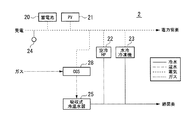
図2は、制御対象機器2の図である。制御対象機器2は、蓄電池20と、PV21(太陽光発電システム)と、空冷HP22(空冷ヒートポンプ)と、水冷冷凍機23と、受電電力メータ24と、吸収式冷温水器25と、CGS28(Co-Generation System)(コジェネレーションシステム)とを備える。制御対象機器2は、太陽熱温水器をさらに備えてもよい。
FIG. 2 is a diagram of the
また、図2は、制御対象機器2のエネルギー授受の図である。制御対象機器2は、受電(電力)及びガスをエネルギー源として、対象建物1の電力需要系(エネルギー消費機器)に電力を供給する。受電系から供給された電力は、対象建物1の電力需要系に供給される。また、受電系からの電力は、蓄電池20に充電されてもよい。制御対象機器2は、受電(電力)及びガスをエネルギー源として、対象建物1の熱需要系に冷熱を供給する。
FIG. 2 is a diagram of energy transfer of the
PV21により発電された電力は、電力需要系に供給される。また、PV21により発電された電力は、蓄電池20に充電されてもよい。
CGS28により発電された電力は、電力需要系に供給される。また、CGS28により発電された電力は、蓄電池20に充電されてもよい。The electric power generated by the
The power generated by the
電力需要系に供給される電力の一部は、空冷HP22及び水冷冷凍機23による冷熱の製造に消費される。
受電電力メータ24は、受電系から制御対象機器2に供給された電力を示す値を所定時間に積算することにより、所定時間に受電系から制御対象機器2に供給された受電量を検出する。A part of the power supplied to the power demand system is consumed in the production of cold by the air-cooled
The received
CGS28は、ガス系から供給されたガスにより、温熱を発生させる。また、CGS28は、ガス系から供給されたガスにより、電力を発生させてもよい。
吸収式冷温水器25は、CGS28から供給された温熱(温水)により、冷熱を製造する。
空冷HP22、水冷冷凍機23及び吸収式冷温水器25により製造された冷熱は、対象建物1の熱需要系に供給される。The
The absorption chiller /
The cold produced by the air-cooled
図3は、管理システム4の図である。管理システム4は、デマンドレスポンス受信部101と、監視部102と、デマンドレスポンス定式化部103と、プロセス値受信部104と、最適スケジューリング部105と、予測部106と、天気予報受信部107と、機器指令値送信部108と、承認部109と、デマンドレスポンス対応判定部110と、運転データベース部201と、蓄電制御装置300とを備える。
FIG. 3 is a diagram of the
運転データベース部201は、デマンドレスポンス信号に基づく受電量の指令値(計画値)を記憶する。また、運転データベース部201は、データベース部202を有する。データベース部202は、需要運転スケジュールデータベース部202aと、DR運転スケジュールデータベース部202bとを有する。
The
以下、監視部102と、最適スケジューリング部105と、予測部106と、承認部109と、デマンドレスポンス対応判定部110と、データベース部202とを、まとめて、「デマンドレスポンス対応型最適運転部100」という。
Hereinafter, the
図4は、管理システム4の図である。デマンドレスポンス受信部101は、デマンドレスポンス信号を受信し、受信したデマンドレスポンス信号を、デマンドレスポンス対応判定部110及びデマンドレスポンス定式化部103に転送する。
FIG. 4 is a diagram of the
デマンドレスポンス定式化部103は、デマンドレスポンス受信部101から転送されたデマンドレスポンス信号を定式化する。デマンドレスポンス定式化部103は、定式化されたデマンドレスポンス信号を示す数式に基づいて、インセンティブ情報及びベースライン情報を、最適スケジューリング部105に転送する。ここで、ベースライン情報は、所定の時間帯における受電量の指令値(計画値)を示す情報である。また、インセンティブ情報は、所定の時間帯における受電量のベースラインからの削減量に対して、需要家に支払われるインセンティブ(例えば、受領額)を示す情報である。
The demand
デマンドレスポンス対応判定部110には、現在時刻情報が入力される。また、デマンドレスポンス対応判定部110には、デマンドレスポンス信号が、デマンドレスポンス受信部101から入力される。デマンドレスポンス対応判定部110は、デマンドレスポンス信号が入力された場合、デマンドレスポンスに対応した動作を実行するか否かを、現在時刻に基づいて、定周期で判定する。
The current time information is input to the demand response
以下、デマンドレスポンスに対応した動作を実行する時間帯を、「デマンドレスポンス時間帯(DR時間帯)」という。デマンドレスポンス対応判定部110は、デマンドレスポンスに対応した動作を実行すると判定した場合、デマンドレスポンス・トリガ信号を、監視部102、最適スケジューリング部105及び予測部106に出力する。
Hereinafter, a time zone in which an operation corresponding to a demand response is executed is referred to as a “demand response time zone (DR time zone)”. When it is determined that the operation corresponding to the demand response is to be executed, the demand response
デマンドレスポンス・トリガ信号は、デマンドレスポンスに対応した動作を制御対象機器2に実行させるためのトリガ信号である。より具体的には、デマンドレスポンス・トリガ信号は、デマンドレスポンスに対応した運転スケジュール(以下、「DR運転スケジュール」という。)を、最適スケジューリング部105に生成(立案)させるためのトリガ信号である。
The demand response trigger signal is a trigger signal for causing the
プロセス値受信部104は、プロセス値、すなわち、所定時間に受電系から制御対象機器2に供給された受電量、対象建物1の電力需要量及び熱需要量を、定周期で収集する。
監視部102は、予測部106及び最適スケジューリング部105に監視トリガ信号を出力するか否かを、プロセス値受信部104により収集されたプロセス値に基づいて、定周期で判定する。The process
The
天気予報受信部107は、天気予報信号を受信する。天気予報信号には、例えば、時間帯毎の気温の予報を示す情報が含まれていてもよい。
予測部106は、監視トリガ信号が監視部102から入力された場合、天気予報信号に基づいて、対象建物1の電力需要量及び熱需要量を予測する。The weather
When the monitoring trigger signal is input from the
最適スケジューリング部105には、予測された電力需要量及び熱需要量が、予測部106から入力される。最適スケジューリング部105は、所定時間(所定期間)における制御対象機器2の需要運転スケジュール情報を生成し、生成した需要運転スケジュール情報を、需要運転スケジュールデータベース部202aに記憶させる。需要運転スケジュール情報には、例えば、電力需要量及び熱需要量を満たすための制御対象機器2の運転スケジュール(起動停止スケジュール)情報が含まれてもよい。
The
最適スケジューリング部105には、デマンドレスポンス・トリガ信号が、デマンドレスポンス対応判定部110から入力される。最適スケジューリング部105は、所定時間(所定期間)における制御対象機器2のDR運転スケジュールを示す情報を生成し、生成したDR運転スケジュールを示す情報を、DR運転スケジュールデータベース部202bに記憶させる。
A demand response trigger signal is input from the demand response
承認部109は、需要運転スケジュール又はDR運転スケジュールを、所定の条件に基づいて選択して承認する。承認部109は、需要運転スケジュールを承認した場合、承認した需要運転スケジュールを示す情報を、需要運転スケジュールデータベース部202aから取得して、機器指令値送信部108に転送する。承認した需要運転スケジュールを示す情報は、受電量の指令値として、機器指令値送信部108から制御対象機器2(例えば、エネルギー消費機器)に送信される。
The
また、承認部109は、DR運転スケジュールを承認した場合、承認したDR運転スケジュールを示す情報を、DR運転スケジュールデータベース部202bから取得して、機器指令値送信部108に転送する。承認したDR運転スケジュールを示す情報は、受電量の指令値として、機器指令値送信部108から制御対象機器2(例えば、エネルギー消費機器)に送信されてもよい。また、承認部109は、画像信号を表示部400に出力する。この画像信号は、承認した需要運転スケジュール又はDR運転スケジュールを示す画像信号である。
Further, when the
機器指令値送信部108は、需要運転スケジュールを示す情報が承認部109から入力された場合、需要運転スケジュールを示す情報を、受電量の指令値として、制御対象機器2に送信する。機器指令値送信部108は、DR運転スケジュールを示す情報が承認部109から入力された場合、DR運転スケジュールを示す情報を、受電量の指令値として、制御対象機器2に送信する。
When the information indicating the demand operation schedule is input from the
表示部400は、承認部109から出力された画像信号に基づいて、画像を表示する。この画像信号は、承認部109が承認した需要運転スケジュール又はDR運転スケジュールを示す画像信号でもよい。この画像信号に基づく画像については、図9を用いて後述する。
The
次に、DR運転スケジュールの生成例を説明する。
デマンドレスポンス信号がPTR(Peak Time Rebate)である場合、所定の時間帯における受電量のベースラインからの削減量に対して、需要家にインセンティブが支払われる。この場合、デマンドレスポンス信号には、時間帯別電力料金と、時間帯別インセンティブと、時間帯別ベースラインとが含まれる。Next, an example of generating a DR operation schedule will be described.
When the demand response signal is PTR (Peak Time Rebate), an incentive is paid to the customer for the amount of power reduction from the baseline in a predetermined time zone. In this case, the demand response signal includes a time zone power charge, a time zone incentive, and a time zone baseline.
デマンドレスポンス定式化部103は、省エネ、省コスト及び省CO2(二酸化炭素)などを実現するためのDR運転スケジュール(運転計画)を生成する。例えば、省コストを実現するためのDR運転スケジュールを生成する場合、デマンドレスポンス定式化部103は、式(1)により表される目的関数Cを最小化するように、運転スケジュールを生成すればよい。
The demand
C=Σ{ki×Li−mi×(Li−Bi)+ni×Pi} …(1)C = Σ {k i × L i −m i × (L i −B i ) + n i × P i } (1)
ここで、Cは、運転期間中のコストを示す。iは、1日を24等分した時間帯を示す符号であり、0時からの経過時間に応じた1〜24のいずれかを示す。kiは、時間帯iにおける電力料金(受電単価)を示す。Liは、時間帯iにおける受電量を示す。miは、時間帯iにおけるインセンティブ(金額など)を示す。Biは、時間帯iにおけるベースラインを示す。niは、時間帯iにおけるガス料金を示す。Piは、時間帯iにおけるガス消費量を示す。Here, C indicates the cost during the operation period. i is a code | symbol which shows the time slot | zone which divided the day into 24 equally, and shows either 1-24 according to the elapsed time from 0:00. k i indicates a power charge (power receiving unit price) in the time zone i. L i indicates the amount of received power in the time zone i. m i indicates the incentives (such as the amount of money) in the time zone i. B i indicates a baseline in time zone i. n i indicates the gas charge in time zone i. P i shows the gas consumption in the time zone i.
受電量の削減可能量Liは、式(2)により表される。The reduction amount L i of the power reception amount is expressed by the equation (2).
Li=Si+Di …(2)L i = S i + D i (2)
ここで、Siは、時間帯別の受電量の削減可能量である。Diは、時間帯別の受電量を示す。Here, S i is the amount of power that can be reduced by time period. D i indicates the time zone of the received power amount.
最適スケジューリング部105は、式(1)により表される目的関数Cを最小化する最適化問題を解く。この最適化問題を解くには、様々な方法が用いられてよい。例えば、最適スケジューリング部105は、天気予報信号に基づいて予測された電力需要量及び熱需要量に基づいて、時間帯別の受電量Diを算出することにより、最適化問題を解いてもよい。The
次に、蓄電制御装置300(図3を参照)について説明する。
図5は、蓄電制御装置300の図である。蓄電制御装置300は、ホールド部301と、演算部302と、蓄電池出力指令値作成部303と、記憶部304とを有する。記憶部304は、非一時的な記録媒体で構成することができる。記憶部304は、図5に示すように蓄電制御装置300の内部に備えられてもよい。また、記憶部304は、蓄電制御装置300の外部に備えられてもよい。ホールド部301と、演算部302と、蓄電池出力指令値作成部303との一部または全部は、例えば、CPU(Central Processing Unit)等のプロセッサが、記憶部304に記憶されたプログラムを実行することにより機能するソフトウェア機能部である。これらの機能部のうち一部または全部は、LSI(Large Scale Integration)やASIC(Application Specific Integrated Circuit)等のハードウェア機能部であってもよい。Next, the power storage control device 300 (see FIG. 3) will be described.
FIG. 5 is a diagram of the power
ホールド部301は、所定時間に受電系から制御対象機器2に供給された受電量(現在値)を、受電電力メータ24からローカル制御装置3(通信システム)を介して受信する。以下、デマンドレスポンス信号に基づく受電量の指令値が定められている時刻を、「ホールド時刻」という。ホールド時刻は、例えば、毎時0分又は毎時30分でもよい。
The
ホールド部301は、現在時刻がホールド時刻(毎時0分又は毎時30分)である場合、所定時間に受電系から制御対象機器2に供給された受電量(現在値)を保持する。つまり、ホールド部301は、現在時刻がホールド時刻(毎時0分又は毎時30分)となる毎に、保持した受電量を更新する。ホールド部301は、保持した受電量の値を、演算部302に出力する。
When the current time is the hold time (0 minutes per hour or 30 minutes per hour), the
演算部302は、所定時間に受電系から制御対象機器2に供給された受電量(現在値)を、受電電力メータ24からローカル制御装置3(通信システム)を介して受信する。演算部302は、所定時間に受電系から制御対象機器2に供給された受電量(現在値)から、ホールド部301により保持された受電量を減算する。つまり、この減算結果は、所定のT時間(例えば、時刻0分から時刻30分までの0.5時間)に受電系から制御対象機器2に供給された受電量を示す。演算部302は、T時間に受電系から制御対象機器2に供給された受電量を、蓄電池出力指令値作成部303に出力する。
The
蓄電池出力指令値作成部303は、デマンドレスポンス信号に基づく受電量の指令値(計画値)を、運転データベース部201から取得する。つまり、蓄電池出力指令値作成部303は、蓄電池20から電力が供給されるエネルギー消費機器への所定時間毎の受電量の指令値を、運転データベース部201から取得する。
The storage battery output command
蓄電池出力指令値作成部303は、T時間に受電系から制御対象機器2に供給された受電量を、演算部302から取得する。蓄電池出力指令値作成部303は、T時間に受電系から制御対象機器2に供給される受電量の指令値に基づいて、T時間よりも短い時間毎の受電量の制限値を算出する。
The storage battery output command
蓄電池出力指令値作成部303は、受電量の指令値(計画値)を満たすように、受電量の制限値に基づいて、蓄電池20の蓄電(充電及び放電)を、ローカル制御装置3(通信システム)を介して制御する。より具体的には、蓄電池出力指令値作成部303は、蓄電池の出力値を示す信号を、ローカル制御装置3(通信システム)を介して蓄電池20に出力する。
The storage battery output command
蓄電池20は、蓄電池の出力値が正値である場合、蓄電池の出力値を示す信号に基づいて放電を実行する。一方、蓄電池20は、蓄電池の出力値が負値である場合、蓄電池の出力値を示す信号に基づいて充電を実行する。
When the output value of the storage battery is a positive value, the
図6は、受電量の制限値の図である。横軸は時刻を示す。縦軸は受電量[kWh]を示す。現在時刻における受電量の制限値は、式(3)により表される。 FIG. 6 is a diagram of the limit value of the amount of received power. The horizontal axis indicates time. The vertical axis represents the amount of power received [kWh]. The limit value of the amount of power received at the current time is expressed by Equation (3).
受電量の制限値=(T−ΔT)/T×(受電量の指令値) …(3) Limit value of power reception amount = (T−ΔT) / T × (command value of power reception amount) (3)
ここで、Tは、予め定められたホールド時刻の間隔(所定時間)である。以下、Tは、一例として、0.5時間(=30分間)であるものとして説明を続ける。ΔTは、現在時刻から次のホールド時刻(毎時30分)までの残り時間である。したがって、「T−ΔT」は、直近のホールド時刻(毎時0分)から現在時刻までの時間である。 Here, T is a predetermined hold time interval (predetermined time). Hereinafter, description will be continued assuming that T is 0.5 hour (= 30 minutes) as an example. ΔT is the remaining time from the current time to the next hold time (30 minutes per hour). Therefore, “T−ΔT” is the time from the most recent hold time (0 minutes per hour) to the current time.
蓄電池の出力値(バッテリ出力)は、例えば、現在時刻における受電量の制限値から、直近のホールド時刻から現在時刻までに受電系から制御対象機器2に供給された受電量を減算した値である。つまり、蓄電池の出力値は、現在時刻における受電量の制限値に対する、直近のホールド時刻から現在時刻までに受電系から制御対象機器2に供給された受電量の乖離に応じて定められる。
The output value (battery output) of the storage battery is, for example, a value obtained by subtracting the amount of power received supplied from the power receiving system to the
図6では、受電量の制限値[kWh]は、時間の経過に応じて直線的に増加するよう定められている。また、直近のホールド時刻から現在時刻までに受電系から制御対象機器2に供給された受電量[kWh]は、一例として、パターンA、パターンB及びパターンCのそれぞれで変化している。パターンAでは、受電系から制御対象機器2に供給された受電量は、受電量の制限値を常に下回っている。パターンBでは、受電系から制御対象機器2に供給された受電量は、受電量の制限値を当初では上回っているが、受電量の制限値を途中から下回っている。パターンCでは、受電系から制御対象機器2に供給された受電量は、受電量の制限値を当初では下回っているが、受電量の制限値を途中から上回っている。
In FIG. 6, the limit value [kWh] of the amount of received power is determined to increase linearly with the passage of time. In addition, the amount of power received [kWh] supplied from the power receiving system to the
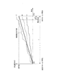
図7は、蓄電池20の出力の図である。最上段には、図6に示すグラフが示されている。また、下段には、パターンA、パターンB及びパターンCのそれぞれにおける、蓄電池の出力値を示すグラフが示されている。蓄電池の出力を示すグラフにおいて、横軸は時刻を示す。縦軸は、蓄電池の出力値[kW]を示す。
FIG. 7 is a diagram of the output of the
パターンAでは、受電系から制御対象機器2に供給された受電量が、受電量の制限値を常に下回っているため、蓄電池20の出力値は、負値となっている。つまり、パターンAでは、蓄電池20は、蓄電池の出力値を示す信号に基づいて、常に充電を実行している。パターンBでは、蓄電池20は、蓄電池の出力値を示す信号に基づいて、当初では放電を実行していたが、途中から充電を実行している。パターンCでは、蓄電池の出力値を示す信号に基づいて、蓄電池20は、当初では充電を実行していたが、途中から放電を実行している。このような制御により、パターンA、パターンB及びパターンCのそれぞれにおいて、T時間に受電系から制御対象機器2に供給された受電量は、受電量の制限値と常に一致することになる。
In the pattern A, the amount of power received from the power receiving system to the
図7には、1日の中で、毎時0分から毎時30分までの30分間の動作が示されている。パターンA、パターンB及びパターンCのそれぞれにおいて、蓄電池20の蓄電に必要なコストは、30分間における充電及び放電の積算値、すなわち、30分間における蓄電池20の出力値の積算値に基づいて算出可能である。また、蓄電池20の蓄電は、受電系から制御対象機器2に供給される受電量の調整に使われている。このため、蓄電池20の蓄電に必要な電力単価は、受電単価と同一である。
FIG. 7 shows an operation for 30 minutes from 0 minutes per hour to 30 minutes per hour in one day. In each of Pattern A, Pattern B, and Pattern C, the cost required to store the
デマンドレスポンス時間帯における受電量の指令値が、インセンティブを算出するためのベースライン(受電量の制限値)となっている場合、所定時間に受電系から制御対象機器2に供給された受電量は、蓄電池の出力値を示す信号に基づいて蓄電池20が蓄電を実行することにより、ベースラインを下回ることが可能となる。このため、需要家は、承認部109により承認された運転スケジュールに応じたインセンティブを、受領することができる。
When the command value of the amount of power received in the demand response time zone is the baseline for calculating the incentive (the limit value of the amount of power received), the amount of power received supplied from the power receiving system to the
次に、蓄電制御装置300の動作手順例を説明する。
図8は、蓄電制御装置300の動作の図である。
(ステップS1)ホールド部301は、所定時間に受電系から制御対象機器2に供給された受電量(現在値)を、受電電力メータ24からローカル制御装置3(通信システム)を介して受信する。Next, an example of an operation procedure of the power
FIG. 8 is a diagram of the operation of the power
(Step S <b> 1) The
(ステップS2)ホールド部301は、現在時刻がホールド時刻(毎時0分又は毎時30分)であるか否かを判定する。現在時刻がホールド時刻である場合(ステップS2:Yes)、ホールド部301は、ステップS3に処理を進める。一方、現在時刻がホールド時刻でない場合(ステップS2:No)、ホールド部301は、ステップS4に処理を進める。
(Step S2) The
(ステップS3)ホールド部301は、所定時間に受電系から制御対象機器2に供給された受電量の現在値を保持(ホールド)する。
(ステップS4)ホールド部301は、保持した受電量の値(ホールド値)を、演算部302に出力する。(Step S <b> 3) The
(Step S <b> 4) The
(ステップS5)演算部302は、所定時間に受電系から制御対象機器2に供給された受電量の現在値から、ホールド部301により保持された受電量の値を減算する。すなわち、演算部302は、所定時間に受電系から制御対象機器2に供給された受電量の現在値と、ホールド部301により保持された受電量の値との差を算出する。
(Step S5) The
(ステップS6)蓄電池出力指令値作成部303は、デマンドレスポンス信号に基づく受電量の指令値(計画値)を、運転データベース部201から取得する。
(ステップS7)蓄電池出力指令値作成部303は、T時間に受電系から制御対象機器2に供給された受電量に基づいて、T時間よりも短い時間毎の受電量の制限値を算出する(式(3)を参照)。(Step S <b> 6) The storage battery output command
(Step S7) The storage battery output command
(ステップS8)蓄電池出力指令値作成部303は、蓄電池の出力値を算出する。ここで、蓄電池の出力値は、現在時刻における受電量の制限値から、直近のホールド時刻から現在時刻までに受電系から制御対象機器2に供給された受電量を減算した値でもよい。
(ステップS9)蓄電池出力指令値作成部303は、蓄電池の出力値を示す信号を、蓄電池20に出力する。(Step S8) The storage battery output command
(Step S <b> 9) The storage battery output command
図9は、蓄電池20の蓄電がインセンティブ受領に与える効果の図である。より具体的には、図9は、運転スケジュール(運転計画)を確認するための画像の図である。この画像は、承認部109から出力された画像信号に基づいて、表示部400に表示されてもよい。運転スケジュールを確認するための画像には、「運転計画と実績」と、DR時間帯の充電コストと、DR時間帯の放電によるインセンティブ受領額と、インセンティブ受領額と、DR時間帯のベースラインとが示されている。
FIG. 9 is a diagram of the effect that the power storage of the
項目「運転計画と実績」には、電力需要の推移と、蓄電池20の蓄電の推移とが、棒グラフにより示されている。この棒グラフの横軸は、時刻を示す。この棒グラフの縦軸は、受電力[kW]を示す。したがって、この棒グラフの1本あたりは、1時間あたりの受電量(電力量)に相当する。また、この棒グラフには、受電力のベースライン(図9では、620[kW])が示されている。
In the item “operation plan and performance”, the transition of power demand and the transition of power storage of the
図9において、DR時間帯の1時間目及び2時間目では、蓄電池20は放電を実行している。DR時間帯の3時間目では、蓄電池20は充電を実行している。DR時間帯の4時間目では、蓄電池20は充電及び放電のいずれも実行していない。図9において、DR時間帯の1時間目、2時間目及び3時間目では、CGS28は、ガス系から供給されたガスにより発電して、電力を発生させている。
In FIG. 9, the
項目「DR時間帯の充電コスト」には、DR時間帯の3時間目における、蓄電池20の充電に必要なコスト「15千円」が示されている。項目「DR時間帯の放電によるインセンティブ受領額」には、蓄電池20の放電により得ることができるインセンティブの受領額「20千円」が示されている。
In the item “charging time in DR time zone”, a cost “15,000 yen” required for charging the
仮に、DR時間帯の1時間目及び2時間目において、蓄電池20が放電を実行しなかった場合、受電系から制御対象機器2に供給された受電力がベースラインを下回ることができず、需要家は、インセンティブを受領することができない。実際には、DR時間帯の1時間目及び2時間目において、蓄電池の出力値を示す信号に基づいて蓄電池20が放電を実行しているので、受電系から制御対象機器2に供給された受電力がベースラインを下回ることができ、需要家は、インセンティブを受領することができる。
If the
項目「インセンティブ受領額」には、最終的に得ることができるインセンティブの受領額「41千円」が示されている。最終的に得ることができるインセンティブの受領額には、蓄電池20の放電により得ることができるインセンティブの受領額「20千円」と、CGS28などの発電により得ることができるインセンティブの受領額「21千円」とが含まれている。項目「DR時間帯のベースライン」には、デマンドレスポンス信号に基づくベースライン「620[kW]」が示されている。
The item “incentive receipt amount” indicates an incentive receipt amount “41 thousand yen” that can be finally obtained. The incentive receipt amount that can be finally obtained includes the incentive receipt amount “20 thousand yen” that can be obtained by discharging the
以上のように、第1の実施形態の蓄電制御装置300は、ホールド部(例えば、ホールド部301)と、演算部(例えば、演算部302)と、取得部(例えば、蓄電池出力指令値作成部303)と、算出部(例えば、蓄電池出力指令値作成部303)と、制御部(例えば、蓄電池出力指令値作成部303)と、を備える。ホールド部は、蓄電池20から電力が供給される機器に受電系から供給された受電量の値を、予め定められた時刻に保持する。演算部は、受電系から機器に供給された受電量の現在値と、予め定められた時刻にホールド部により保持された受電量の値と、の差を算出する。取得部は、予め定められた時刻の間隔により定まる所定時間毎の受電量の指令値(例えば、図6では、時刻30分での受電量の指令値)を取得する。算出部は、所定時間(例えば、30分間)毎の受電量の指令値(デマンドレスポンス信号に基づく受電量の指令値)に基づいて、所定時間よりも短い時間毎の受電量の制限値を算出する。制御部は、演算部により算出された差と、受電量の制限値と、に基づいて、蓄電池の蓄電を制御する。
As described above, the power
管理システム4は、蓄電制御装置(例えば、蓄電制御装置300)と、運転データベース部201とを備える。運転データベース部201は、デマンドレスポンス信号に基づく受電量の指令値(計画値)を記憶する。
The
第1の実施形態の蓄電制御方法は、蓄電制御装置300における蓄電制御方法であって、保持するステップと、差を算出するステップと、取得するステップと、制限値を算出するステップと、制御するステップと、を有する。保持するステップでは、ホールド部(例えば、ホールド部301)が、蓄電池20から電力が供給される機器に受電系から供給された受電量の値を、予め定められた時刻に保持する。差を算出するステップでは、演算部(例えば、演算部302)が、受電系から機器に供給された受電量の現在値と、予め定められた時刻にホールド部により保持された受電量の値と、の差を算出する。取得するステップでは、取得部(例えば、蓄電池出力指令値作成部303)が、予め定められた時刻の間隔により定まる所定時間毎の受電量の指令値を取得する。制限値を算出するステップでは、算出部(例えば、蓄電池出力指令値作成部303)が、所定時間毎の受電量の指令値に基づいて、所定時間よりも短い時間毎の受電量の制限値を算出する。制御するステップでは、制御部(例えば、蓄電池出力指令値作成部303)が、演算部により算出された差と、受電量の制限値と、に基づいて、蓄電池20の蓄電を制御する。
The power storage control method according to the first embodiment is a power storage control method in the power
第1の実施形態の蓄電制御プログラムは、コンピュータに、保持する手順と、差を算出する手順と、取得する手順と、制限値を算出する手順と、制御する手順と、を実行させる。保持する手順では、蓄電制御プログラムは、コンピュータに、蓄電池20から電力が供給される機器に受電系から供給された受電量の値を、予め定められた時刻に保持する手順を実行させる。差を算出する手順では、蓄電制御プログラムは、コンピュータに、受電系から機器に供給された受電量の現在値と、予め定められた時刻に保持された受電量の値と、の差を算出する手順を実行させる。取得する手順では、蓄電制御プログラムは、コンピュータに、予め定められた時刻の間隔により定まる所定時間毎の受電量の指令値を取得する手順を実行させる。制限値を算出する手順では、蓄電制御プログラムは、コンピュータに、所定時間毎の受電量の指令値に基づいて、所定時間よりも短い時間毎の受電量の制限値を算出する手順を実行させる。制御する手順では、蓄電制御プログラムは、コンピュータに、算出された差と、受電量の制限値と、に基づいて、蓄電池20の蓄電を制御する手順を実行させる。
The power storage control program according to the first embodiment causes a computer to execute a holding procedure, a procedure for calculating a difference, a procedure for obtaining, a procedure for calculating a limit value, and a procedure for controlling. In the holding procedure, the power storage control program causes the computer to execute a procedure of holding, at a predetermined time, the value of the amount of power received from the power receiving system to the device to which power is supplied from the
記録媒体は、蓄電制御プログラムを記録したコンピュータ読み取り可能な記録媒体である。 The recording medium is a computer-readable recording medium on which the power storage control program is recorded.
この構成により、制御部は、演算部により算出された差と、受電量の制限値と、に基づいて、蓄電池の蓄電を制御する。これにより、第1の実施形態の蓄電制御装置300、管理システム4、蓄電制御方法、蓄電制御プログラム及び記録媒体は、機器に供給される電力を、デマンドレスポンス信号に基づく受電量の指令値以上に、効率良く制御することができる。また、第1の実施形態の蓄電制御装置300、管理システム4、蓄電制御方法、蓄電制御プログラム及び記録媒体は、コストメリットを得ることができる。
With this configuration, the control unit controls the storage of the storage battery based on the difference calculated by the calculation unit and the power reception amount limit value. As a result, the power
第1の実施形態の蓄電池出力指令値作成部303は、所定時間(例えば、直近のホールド時刻から現在時刻まで)に受電系から制御対象機器2に供給された受電量と、デマンドレスポンス信号に基づく受電量の指令値とに基づいて、蓄電池の出力値を示す信号を、ローカル制御装置3(通信システム)を介して蓄電池20に出力してもよい。
The storage battery output command
第1の実施形態の蓄電池出力指令値作成部303は、現在時刻における受電量の制限値(例えば、式(3)を参照)に基づいて、蓄電池の出力値を示す信号を、蓄電池20に出力してもよい。
The storage battery output command
第1の実施形態の蓄電池出力指令値作成部303は、現在時刻から次のホールド時刻(毎時30分)までの残り時間ΔTに基づいて(例えば、式(3)を参照)、蓄電池の出力値を示す信号を、蓄電池20に出力してもよい。
The storage battery output command
第1の実施形態の蓄電池出力指令値作成部303は、現在時刻における受電量の制限値から、直近のホールド時刻から現在時刻までに受電系から制御対象機器2に供給された受電量を減算した値、すなわち、制限値に対する受電量の乖離(例えば、図7を参照)に基づいて、蓄電池の出力値を示す信号を、蓄電池20に出力してもよい。
The storage battery output command
(第2の実施形態)
第2の実施形態では、蓄電池20の放電をホールド時刻の直前にまとめて実行する点が、第1の実施形態と相違する。以下では、第1の実施形態との相違点についてのみ説明する。(Second Embodiment)
The second embodiment is different from the first embodiment in that the discharge of the
蓄電池20の蓄電は、受電系から制御対象機器2に供給される受電量の調整に使われている。このため、蓄電池20の充電及び放電に必要な電力単価は、受電単価と同一である。したがって、蓄電池20は、昼間のピーク時間帯における高い電力単価で充電している場合がある。例えば、第1の実施形態において、項目「DR時間帯の充電コスト」は、DR時間帯の3時間目における蓄電池20の充電のコスト「15千円」(図9を参照)を示している。なお、第2の実施形態では、受電電力メータ24は、受電系から制御対象機器2に供給された電力を示す値を所定時間に積算することにより、その所定時間に受電系から制御対象機器2に供給された受電量を検出する。受電電力メータ24は、制御対象機器2から受電系に供給された電力を示す値をその所定時間に積算することにより、その所定時間に制御対象機器2から受電系に流れた電力量(以下、「逆潮流した電力量」という。)を検出する。蓄電池出力指令値作成部303は、その所定時間に受電系から制御対象機器2に供給された受電量と、その所定時間に逆潮流した電力量との差を検出することができる。
The electricity stored in the
蓄電池20は、夜間に充電を予め実行した場合、昼間のピーク時間帯では、昼間の電力単価よりも安い電力単価で、充電を実行することができる。このため、蓄電制御装置は、DR時間帯の充電コストを低減することができ、コストメリットが高くなる。また、蓄電池20の容量は、放電量を少なくできれば、小さくすることができる。
When the
つまり、蓄電池20が事前に(例えば、前日の夜間に)に充電を実行すれば、DR時間帯では蓄電池20が充電を実行する必要がないので、蓄電制御装置は、第1の実施形態と比較して、さらにコストメリットを得ることができる。また、蓄電池20の容量が小さいことにより、蓄電制御装置は、第1の実施形態と比較して、さらにコストメリットを得ることができる。
That is, if the
図10は、受電量の制限値の図である。横軸は時刻を示す。縦軸は受電量[kWh]を示す。直近のホールド時刻から現在時刻までに受電系から制御対象機器2に供給された受電量[kWh]は、一例として、パターンA、パターンB及びパターンDのそれぞれで変化している。
FIG. 10 is a diagram of the power reception amount limit value. The horizontal axis indicates time. The vertical axis represents the amount of power received [kWh]. The amount of power received [kWh] supplied from the power receiving system to the
パターンA及びパターンBは、図6と同様である。パターンDでは、受電系から制御対象機器2に供給された受電量は、受電量の制限値を当初では上回っているが、現在時刻から次のホールド時刻までの残り時間ΔTとなってから、受電量の制限値を下回っている。これは、現在時刻から次のホールド時刻までの残り時間ΔTとなってから、すなわち、次のホールド時刻の直前に、蓄電池の出力値を示す信号に基づいて蓄電池20が放電をまとめて実行したためである。
Pattern A and pattern B are the same as in FIG. In Pattern D, the amount of power received from the power receiving system to the
次のホールド時刻まで残り時間ΔTとなった現在時刻に、制限値に対する受電量の超過量ΔWとなった段階で蓄電池20の放電を実行させるため、蓄電池出力指令値作成部303は、残り時間ΔTと、受電量の超過量ΔWとにより定まる関数に基づいて、蓄電池の出力値を示す信号を、蓄電池20に出力する。
In order to cause the
残り時間ΔTと、制限値に対する受電量の超過量ΔW[kWh]とにより定まる関数は、蓄電池が出力可能(放電可能)である最大電力値X[kW]を用いて、式(4)により表される。 The function determined by the remaining time ΔT and the excess amount ΔW [kWh] of the amount of power received with respect to the limit value is expressed by Equation (4) using the maximum power value X [kW] that the storage battery can output (discharge). Is done.
ΔW/(ΔT/T)=X …(4) ΔW / (ΔT / T) = X (4)
ここで、蓄電池が出力可能である最大電力値Xに対して余裕を持たせるため、受電量の超過量ΔWには、予め定められた電力量α[kWh]が加算されてもよい。 Here, in order to provide a margin for the maximum power value X that can be output by the storage battery, a predetermined power amount α [kWh] may be added to the power receiving amount excess amount ΔW.
(ΔW+α)/(ΔT/T)=X …(5) (ΔW + α) / (ΔT / T) = X (5)
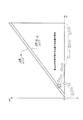
図11は、残り時間と、受電量の超過量との関係の図である。横軸は残り時間ΔTを示す。縦軸は、制限値に対する受電量の超過量ΔWを示す。残り時間ΔTは、直近のホールド時刻に近いほど大きい値であるが、次のホールド時刻に近いほど小さい値になる。式(4)及び式(5)が示すように、残り時間ΔTが小さいほど、蓄電池20が許容可能な受電量の超過量ΔWは小さい。換言すれば、蓄電池が出力可能である最大電力値Xが大きいほど、残り時間ΔTが小さくても、蓄電池は、制限値に対する受電量の超過量ΔWを補償することが可能である。
FIG. 11 is a diagram illustrating a relationship between the remaining time and the excess amount of the power reception amount. The horizontal axis indicates the remaining time ΔT. The vertical axis indicates the power reception excess ΔW with respect to the limit value. The remaining time ΔT increases as it approaches the latest hold time, but decreases as it approaches the next hold time. As shown in Expression (4) and Expression (5), the smaller the remaining time ΔT, the smaller the excess amount ΔW of the power reception amount that the
図10に示すパターンDを例に説明すれば、受電量の超過量ΔWは、負値から始まり、受電量の制限値を超えた段階で正値となっている。さらに、受電量の超過量ΔWは、正値のまま次第に増加するが、式(5)に示す関係が満たされた段階で、負値となるまで減少する。これは、式(5)に示す関係が満たされた段階で、蓄電池の出力値を示す信号に基づいて、蓄電池20が放電をまとめて実行したためである。受電量の超過量ΔWは、残り時間ΔT=0、すなわち、ホールド時刻では、所定の負値となっている。
If the pattern D shown in FIG. 10 is described as an example, the excess amount ΔW of the received power amount starts from a negative value and becomes a positive value when the limit value of the received power amount is exceeded. Furthermore, the excess amount ΔW of the amount of received power gradually increases while maintaining a positive value, but decreases until it reaches a negative value when the relationship shown in Expression (5) is satisfied. This is because the
図11において、式(4)又は式(5)により定まる直線の傾きは、蓄電池が出力可能である最大電力値Xに応じて、それぞれ大きくなる。つまり、蓄電池が出力可能である最大電力値Xが大きい蓄電池ほど、残り時間ΔTが少なくても、制限値に対する受電量の超過量ΔWを補償することが可能であり、電力需要量の変動に対して優位である。 In FIG. 11, the slope of the straight line determined by Expression (4) or Expression (5) increases according to the maximum power value X that can be output from the storage battery. In other words, a storage battery with a large maximum power value X that can be output from the storage battery can compensate for an excess amount ΔW of the amount of power received with respect to the limit value even if the remaining time ΔT is small. Is superior.
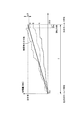
図12は、蓄電池20の出力の図である。最上段には、図10に示すグラフが示されている。また、下段には、パターンA、パターンB及びパターンDのそれぞれにおける、蓄電池の出力値を示すグラフが示されている。蓄電池の出力を示すグラフにおいて、横軸は時刻を示す。縦軸は、蓄電池の出力値[kW]を示す。
FIG. 12 is a diagram of the output of the
パターンAでは、残り時間ΔTとなった時点で、式(5)に示す関係が満たされず、受電系から制御対象機器2に供給された受電量が、受電量の制限値を下回っているため、蓄電池20の出力値は、常に値0となっている。つまり、パターンAでは、蓄電池20は、蓄電池の出力値を示す信号に基づいて、充電及び放電のいずれも実行していない。パターンBも同様である。これにより、「DR時間帯の充電コスト」(図14を用いて後述する)が発生しないので、蓄電制御装置は、コストメリットを得ることができる。
In Pattern A, when the remaining time ΔT is reached, the relationship shown in Expression (5) is not satisfied, and the amount of power received from the power receiving system to the
一方、パターンDでは、残り時間ΔTとなった時点で、式(5)に示す関係が満たされ、受電系から制御対象機器2に供給された受電量が、受電量の制限値を上回っているため、蓄電池20は、残り時間ΔTとなった時点で放電をまとめて実行している。このような制御により、パターンA、パターンB及びパターンDのそれぞれにおいて、T時間に受電系から制御対象機器2に供給された受電量は、少なくともホールド時刻では、受電量の制限値を満たすことになる。
On the other hand, in the pattern D, when the remaining time ΔT is reached, the relationship shown in Expression (5) is satisfied, and the amount of power received from the power receiving system to the
次に、蓄電制御装置300の動作手順例を説明する。
図13は、蓄電制御装置300の動作の図である。
ステップSa1〜ステップSa7は、図8に示すステップS1〜ステップS7と同様である。Next, an example of an operation procedure of the power
FIG. 13 is a diagram of the operation of the power
Steps Sa1 to Sa7 are the same as steps S1 to S7 shown in FIG.
(ステップSa8)蓄電池出力指令値作成部303は、制限値に対する受電量の超過量ΔWが、蓄電池20が許容可能な最大の受電量の超過量以上であるか否か、すなわち、式(4)又は式(5)に示す関係が満たされているか否かを判定する。制限値に対する受電量の超過量ΔWが、蓄電池20が許容可能な最大の受電量の超過量以上である場合(ステップSa8)、蓄電池出力指令値作成部303は、ステップSa9に処理を進める。一方、制限値に対する受電量の超過量ΔWが、蓄電池20が許容可能な最大の受電量の超過量未満である場合(ステップSa8)、蓄電池出力指令値作成部303は、ステップSa10に処理を進める。
(Step Sa8) The storage battery output command
(ステップSa9)蓄電池出力指令値作成部303は、蓄電池の出力値を、蓄電池が出力可能である最大電力値Xと定める。
(ステップSa10)蓄電池出力指令値作成部303は、蓄電池の出力値を値0と定める。(Step Sa9) The storage battery output command
(Step Sa10) The storage battery output command
(ステップSa11)蓄電池出力指令値作成部303は、蓄電池の出力値を示す信号を、ローカル制御装置3(通信システム)を介して蓄電池20に出力する。蓄電池の出力値が最大電力値Xと定められている場合、蓄電池20は、最大電力値Xで放電する。一方、蓄電池の出力値が値0と定められている場合、蓄電池20は、充電及び放電のいずれも実行しない。
(Step Sa11) The storage battery output command
図14は、蓄電池20の蓄電がインセンティブ受領に与える効果の図である。より具体的には、図14は、運転スケジュール(運転計画)を確認するための画像の図である。この画像は、承認部109から出力された画像信号に基づいて、表示部400に表示されてもよい。
FIG. 14 is a diagram of the effect that the
図14において、DR時間帯の1時間目及び2時間目では、蓄電池20は放電を実行している。DR時間帯の3時間目では、第1の実施形態と異なり、蓄電池20は充電及び放電のいずれも実行していない。DR時間帯の4時間目では、蓄電池20は充電及び放電のいずれも実行していない。図14において、DR時間帯の1時間目、2時間目及び3時間目では、CGS28は、ガス系から供給されたガスにより発電して、電力を発生させている。
In FIG. 14, the
第1の実施形態と異なり、項目「DR時間帯の充電コスト」には、DR時間帯における、蓄電池20の充電に必要なコスト「0千円」が示されている。このように、第2の実施形態の蓄電制御装置300は、第1の実施形態と比較して、DR時間帯の充電コストを低減することができ、コストメリットが高くなる。
Unlike the first embodiment, the item “charging time in DR time zone” indicates a cost “0,000 yen” required for charging the
以上のように、第2の実施形態の制御部(例えば、蓄電池出力指令値作成部303)は、制限値を超えて制御対象機器2に供給された受電量が、蓄電池20が出力可能である最大電力値Xに基づく電力量以上、すなわち、蓄電池20が許容可能な受電量以上である場合、予め定められた時刻(次のホールド時刻)までに、蓄電池20の蓄電をまとめて制御してもよい(例えば、図12の最下段を参照)。
As described above, the
この構成により、制御部は、予め定められた時刻(ホールド時刻)までに、蓄電池20の蓄電をまとめて制御してもよい。これにより、第2の実施形態の蓄電制御装置300、管理システム4、蓄電制御方法、蓄電制御プログラム及び記録媒体は、機器に供給される電力を、デマンドレスポンス信号に基づく受電量の指令値以上に、より効率良く制御することができる。また、第2の実施形態の蓄電制御装置300、管理システム4、蓄電制御方法、蓄電制御プログラム及び記録媒体は、コストメリットをより得ることができる。
With this configuration, the control unit may collectively control the storage of the
第2の実施形態の蓄電池出力指令値作成部303は、蓄電池20が出力可能である最大電力値Xに基づいて、蓄電池の出力値を示す信号を、蓄電池20に出力してもよい。
第2の実施形態の蓄電池出力指令値作成部303は、蓄電池が出力可能である最大電力値Xに対してマージン値だけ少ない値に基づいて、蓄電池の出力値を示す信号を、蓄電池20に出力してもよい。このマージン値は、例えば、蓄電池20の放電特性に基づいて定められる。このマージン値は、例えば、式(5)や図11に示す電力量αである。The storage battery output command
The storage battery output command
(第3の実施形態)
第3の実施形態では、受電量が指令値を超過しないように蓄電池20が放電する点が、第2の実施形態と相違する。以下では、第2の実施形態との相違点についてのみ説明する。第3の実施形態では、逆潮流が発生しない前提で説明する。(Third embodiment)
The third embodiment is different from the second embodiment in that the
受電電力メータ24は、受電系から制御対象機器2に供給された電力を示す値を所定時間に積算することにより、その所定時間に受電系から制御対象機器2に供給された受電量を検出する。
The received
図15は、受電量の制限値の図である。横軸は時刻を示す。縦軸は受電量[kWh]を示す。直近のホールド時刻から現在時刻までに受電系から制御対象機器2に供給された受電量[kWh]は、一例として、パターンA、パターンB及びパターンEのそれぞれで変化している。
FIG. 15 is a diagram of the power reception amount limit value. The horizontal axis indicates time. The vertical axis represents the amount of power received [kWh]. The amount of power received [kWh] supplied from the power receiving system to the
パターンA及びパターンBは、図10と同様である。パターンEでは、受電系から制御対象機器2に供給された受電量は、受電量の制限値を当初では上回っているが、現在時刻から次のホールド時刻までの残り時間ΔTとなってから、受電量の制限値を下回っている。これは、現在時刻から次のホールド時刻までの残り時間ΔTとなってから、すなわち、次のホールド時刻の直前に、蓄電池の出力値を示す信号に基づいて蓄電池20が放電をまとめて実行したためである。残り時間ΔTは、図12に示す場合と比較して長い。パターンEでは、受電量が指令値を超過しない点が、図10に示すパターンDとは異なる。
Pattern A and pattern B are the same as in FIG. In pattern E, the amount of power received from the power receiving system to the
図16は、蓄電池20の出力の図である。最上段には、図15に示すグラフが示されている。また、下段には、パターンA、パターンB及びパターンEのそれぞれにおける、蓄電池の出力値を示すグラフが示されている。蓄電池の出力を示すグラフにおいて、横軸は時刻を示す。縦軸は、蓄電池の出力値[kW]を示す。
FIG. 16 is a diagram of the output of the
パターンAでは、残り時間ΔTとなった時点で、式(5)に示す関係が満たされず、受電系から制御対象機器2に供給された受電量が、受電量の制限値を下回っている。このため、蓄電池20の出力値は、常に値0となっている。つまり、パターンAでは、蓄電池20は、充電及び放電のいずれも実行していない。パターンBも同様である。これにより、「DR時間帯の充電コスト」が発生しないので、蓄電制御装置300は、コストメリットを得ることができる。
In the pattern A, when the remaining time ΔT is reached, the relationship shown in the equation (5) is not satisfied, and the amount of power received from the power receiving system to the
パターンEでは、図12に示す場合と比較して長い残り時間ΔTとなった時点で、式(5)に示す関係が満たされ、受電系から制御対象機器2に供給された受電量が、受電量の制限値を上回っている。このため、蓄電池20は、残り時間ΔTとなった時点で、放電をまとめて実行する。これにより、パターンA、パターンB及びパターンEのそれぞれにおいて、T時間に受電系から制御対象機器2に供給された受電量は、少なくともホールド時刻では、受電量の制限値を満たすことができる。
In pattern E, when the remaining time ΔT is longer than that in the case shown in FIG. 12, the relationship shown in Expression (5) is satisfied, and the amount of power received from the power receiving system to the
以上述べた少なくともひとつの実施形態の蓄電制御装置300によれば、演算部302により算出された差と受電量の制限値とに基づいて蓄電池20の蓄電を制御する蓄電池出力指令値作成部303を持つことにより、機器に供給される電力を、デマンドレスポンス信号に基づく受電量の指令値以上に、効率良く制御することが可能となる。
According to the power
以上、本発明のいくつかの実施形態を説明したが、これらの実施形態は、例として提示したものであり、発明の範囲を限定することは意図していない。これら実施形態は、その他の様々な形態で実施されることが可能であり、発明の要旨を逸脱しない範囲で、種々の省略、置き換え、変更を行うことができる。これら実施形態やその変形は、発明の範囲や要旨に含まれると同様に、特許請求の範囲に記載された発明とその均等の範囲に含まれるものである。 As mentioned above, although some embodiment of this invention was described, these embodiment is shown as an example and is not intending limiting the range of invention. These embodiments can be implemented in various other forms, and various omissions, replacements, and changes can be made without departing from the spirit of the invention. These embodiments and their modifications are included in the scope and gist of the invention, and are also included in the invention described in the claims and the equivalents thereof.
例えば、実施形態の制御システムSYは、少なくともその一部が、クラウドサーバ装置により構成されていてもよい。すなわち、実施形態の制御システムSYが実行する処理の少なくとも一部は、クラウド・コンピューティングにより実行されてもよい。 For example, at least a part of the control system SY of the embodiment may be configured by a cloud server device. That is, at least a part of the processing executed by the control system SY of the embodiment may be executed by cloud computing.
このクラウド・コンピューティングには、アプリケーション(ソフトウェア)をサービスとして提供するSaaS(Software as a Service)と、アプリケーションを稼働させるための基盤(プラットフォーム)をサービスとして提供するPaaS(Platform as a Service)と、蓄電制御装置、中央演算処理装置及びストレージなどのリソースをサービス(パブリッククラウド)として提供するIaaS(Infrastructure as a Service)とのうち、少なくとも一つが含まれていてもよい。例えば、このクラウド・コンピューティングには、クラウド・サービス提供層(PaaS)により、インターネットを介した遠隔操作が含まれていてもよい。 This cloud computing includes SaaS (Software as a Service) that provides an application (software) as a service, PaaS (Platform as a Service) that provides a platform (platform) for operating the application as a service, At least one of IaaS (Infrastructure as a Service) that provides resources such as a power storage control device, a central processing unit, and storage as a service (public cloud) may be included. For example, this cloud computing may include remote operation via the Internet by a cloud service providing layer (PaaS).
実施形態の制御システムSYは、その監視、障害対応及び運用のうち少なくとも一つが、代行サービスにより行われていてもよい。例えば、ASP(Application Service Provider)が代行して、制御システムSYを監視、障害対応及び運用してもよい。また、実施形態の制御システムSYは、その監視、障害対応及び運用が、複数の主体によりされてもよい。 In the control system SY of the embodiment, at least one of the monitoring, the failure handling, and the operation may be performed by a proxy service. For example, an ASP (Application Service Provider) may act on behalf of the control system SY to monitor, troubleshoot and operate. Further, the control system SY of the embodiment may be monitored, handled by a failure, and operated by a plurality of entities.
なお、上記に説明した制御システムSYを実現するためのプログラムをコンピュータ読み取り可能な記録媒体に記録して、この記録媒体に記録されたプログラムをコンピュータシステムに読み込ませ、実行することにより、実行処理を行ってもよい。なお、ここでいう「コンピュータシステム」とは、OSや周辺機器等のハードウェアを含むものであってもよい。 The program for realizing the control system SY described above is recorded on a computer-readable recording medium, and the program recorded on the recording medium is read into the computer system and executed, thereby executing the execution process. You may go. Here, the “computer system” may include an OS and hardware such as peripheral devices.
また、「コンピュータシステム」は、WWWシステムを利用している場合であれば、ホームページ提供環境(あるいは表示環境)も含むものとする。また、「コンピュータ読み取り可能な記録媒体」とは、フレキシブルディスク、光磁気ディスク、ROM、フラッシュメモリ等の書き込み可能な不揮発性メモリ、CD−ROM等の可搬媒体、コンピュータシステムに内蔵されるハードディスク等の記憶装置のことをいう。 Further, the “computer system” includes a homepage providing environment (or display environment) if a WWW system is used. The “computer-readable recording medium” means a flexible disk, a magneto-optical disk, a ROM, a writable nonvolatile memory such as a flash memory, a portable medium such as a CD-ROM, a hard disk built in a computer system, etc. This is a storage device.
さらに「コンピュータ読み取り可能な記録媒体」とは、インターネット等のネットワークや電話回線等の通信回線を介してプログラムが送信された場合のサーバやクライアントとなるコンピュータシステム内部の揮発性メモリ(例えばDRAM(Dynamic Random Access Memory))のように、一定時間プログラムを保持しているものも含むものとする。
また、上記プログラムは、このプログラムを記憶装置等に格納したコンピュータシステムから、伝送媒体を介して、あるいは、伝送媒体中の伝送波により他のコンピュータシステムに伝送されてもよい。ここで、プログラムを伝送する「伝送媒体」は、インターネット等のネットワーク(通信網)や電話回線等の通信回線(通信線)のように情報を伝送する機能を有する媒体のことをいう。
また、上記プログラムは、前述した機能の一部を実現するためのものであっても良い。さらに、前述した機能をコンピュータシステムにすでに記録されているプログラムとの組み合わせで実現できるもの、いわゆる差分ファイル(差分プログラム)であっても良い。Further, the “computer-readable recording medium” means a volatile memory (for example, DRAM (Dynamic DRAM) in a computer system that becomes a server or a client when a program is transmitted through a network such as the Internet or a communication line such as a telephone line. Random Access Memory)), etc., which hold programs for a certain period of time.
The program may be transmitted from a computer system storing the program in a storage device or the like to another computer system via a transmission medium or by a transmission wave in the transmission medium. Here, the “transmission medium” for transmitting the program refers to a medium having a function of transmitting information, such as a network (communication network) such as the Internet or a communication line (communication line) such as a telephone line.
The program may be for realizing a part of the functions described above. Furthermore, what can implement | achieve the function mentioned above in combination with the program already recorded on the computer system, and what is called a difference file (difference program) may be sufficient.
Claims (9)
蓄電池から電力が供給される機器に受電系から供給された受電量の現在値と、受電量の指令値が定められている時刻の間隔である所定時間毎に保持された受電量の値との差を算出する演算部と、
前記デマンドレスポンス信号に基づくインセンティブを得ることが可能な運転スケジュールを、前記受電量の指令値として承認する承認部と、
承認された前記受電量の指令値に基づいて、前記所定時間よりも短い時間毎の受電量の制限値を算出する算出部と、
前記演算部により算出された前記差が前記受電量の制限値を超える場合、前記蓄電池の放電を制御する制御部と、
を備える管理システム。 A demand response receiving unit for acquiring a demand response signal for suppressing power;
The current value of the amount of power received from the power receiving system to the device to which power is supplied from the storage battery, and the value of the amount of power received every predetermined time, which is the time interval at which the command value for the amount of power received is determined An arithmetic unit for calculating the difference;
The operation schedule which can obtain incentives based on the demand response signal, and authorization unit authorizing a command value of the received power amount,
Based on the approved command value of the received power amount, a calculation unit that calculates a limit value of the received power amount for each time shorter than the predetermined time;
If the difference calculated by the calculation unit exceeds the limit value of the power receiving amount, and a control unit for controlling the discharge of the pre-SL battery,
A management system comprising:
を更に備える、請求項1から請求項5のいずれか一項に記載の管理システム。 The management system according to any one of claims 1 to 5 , further comprising an operation database unit that stores the command value.
前記管理システムが、電力を抑制するためのデマンドレスポンス信号を取得するステップと、
前記管理システムが、蓄電池から電力が供給される機器に受電系から供給された受電量の現在値と、受電量の指令値が定められている時刻の間隔である所定時間毎に保持された受電量の値との差を算出するステップと、
前記管理システムが、前記デマンドレスポンス信号に基づくインセンティブを得ることが可能な運転スケジュールを、前記受電量の指令値として承認するステップと、
前記管理システムが、承認された前記受電量の指令値に基づいて、前記所定時間よりも短い時間毎の受電量の制限値を算出するステップと、
前記管理システムが、算出された前記差が前記受電量の制限値を超える場合、前記蓄電池の放電を制御するステップと、
を有する管理方法。 A management method in a management system,
The management system acquiring a demand response signal for suppressing power; and
The management system receives power held at predetermined time intervals that are intervals between the current value of the amount of power received from the power receiving system and the command value for the amount of power received, to a device to which power is supplied from the storage battery. Calculating a difference from the quantity value;
A step in which the management system, the demand can operation schedule to obtain incentives based on the response signal, approved as a command value of the received power amount,
The management system calculates a power reception amount limit value for each time shorter than the predetermined time based on the approved power reception amount command value;
A step wherein the management system, if said difference calculated exceeds the limit value of the power receiving amount, for controlling the discharge of the pre-SL battery,
Management method.
電力を抑制するためのデマンドレスポンス信号を取得する手順と、
蓄電池から電力が供給される機器に受電系から供給された受電量の現在値と、受電量の指令値が定められている時刻の間隔である所定時間毎に保持された受電量の値との差を算出する手順と、
前記デマンドレスポンス信号に基づくインセンティブを得ることが可能な運転スケジュールを、前記受電量の指令値として承認する手順と、
承認された前記受電量の指令値に基づいて、前記所定時間よりも短い時間毎の受電量の制限値を算出する手順と、
算出された前記差が前記受電量の制限値を超える場合、前記蓄電池の放電を制御する手順と、
を実行させるための管理プログラム。 On the computer,
A procedure for acquiring a demand response signal for suppressing power,
The current value of the amount of power received from the power receiving system to the device to which power is supplied from the storage battery, and the value of the amount of power received every predetermined time, which is the time interval at which the command value for the amount of power received is determined The procedure to calculate the difference,
A step of said demand capable operating schedule to obtain incentives based on the response signal, approved as a command value of the received power amount,
A procedure for calculating a power reception amount limit value for each time shorter than the predetermined time, based on the approved command value of the power reception amount,
If the difference calculated exceeds the limit value of the power receiving amount, the procedure for controlling the discharge of the pre-SL battery,
Management program to execute.
電力を抑制するためのデマンドレスポンス信号を取得する手順と、
蓄電池から電力が供給される機器に受電系から供給された受電量の現在値と、受電量の指令値が定められている時刻の間隔である所定時間毎に保持された受電量の値との差を算出する手順と、
前記デマンドレスポンス信号に基づくインセンティブを得ることが可能な運転スケジュールを、前記受電量の指令値として承認する手順と、
承認された前記受電量の指令値に基づいて、前記所定時間よりも短い時間毎の受電量の制限値を算出する手順と、
算出された前記差が前記受電量の制限値を超える場合、前記蓄電池の放電を制御する手順と、
を実行させるための管理プログラムを記録したコンピュータ読み取り可能な記録媒体。 On the computer,
A procedure for acquiring a demand response signal for suppressing power,
The current value of the amount of power received from the power receiving system to the device to which power is supplied from the storage battery, and the value of the amount of power received every predetermined time, which is the time interval at which the command value for the amount of power received is determined The procedure to calculate the difference,
A step of said demand capable operating schedule to obtain incentives based on the response signal, approved as a command value of the received power amount,
A procedure for calculating a power reception amount limit value for each time shorter than the predetermined time, based on the approved command value of the power reception amount,
If the difference calculated exceeds the limit value of the power receiving amount, the procedure for controlling the discharge of the pre-SL battery,
The computer-readable recording medium which recorded the management program for performing this.
Applications Claiming Priority (3)
| Application Number | Priority Date | Filing Date | Title |
|---|---|---|---|
| JP2013188538 | 2013-09-11 | ||
| JP2013188538 | 2013-09-11 | ||
| PCT/JP2014/067005 WO2015037307A1 (en) | 2013-09-11 | 2014-06-26 | Power storage control device, management system, power storage control method, power storage control program, and memory medium |
Publications (2)
| Publication Number | Publication Date |
|---|---|
| JPWO2015037307A1 JPWO2015037307A1 (en) | 2017-03-02 |
| JP6239631B2 true JP6239631B2 (en) | 2017-11-29 |
Family
ID=52665431
Family Applications (1)
| Application Number | Title | Priority Date | Filing Date |
|---|---|---|---|
| JP2015536466A Active JP6239631B2 (en) | 2013-09-11 | 2014-06-26 | Management system, management method, management program, and recording medium |
Country Status (6)
| Country | Link |
|---|---|
| US (1) | US9543775B2 (en) |
| EP (1) | EP3046199A4 (en) |
| JP (1) | JP6239631B2 (en) |
| CN (1) | CN104620457B (en) |
| SG (1) | SG11201500154YA (en) |
| WO (1) | WO2015037307A1 (en) |
Families Citing this family (12)
| Publication number | Priority date | Publication date | Assignee | Title |
|---|---|---|---|---|
| US9912157B2 (en) | 2013-03-04 | 2018-03-06 | Nec Corporation | Energy management system and energy management method |
| JP6356502B2 (en) | 2014-06-20 | 2018-07-11 | 株式会社東芝 | Equipment operation setting device and equipment operation setting value determination program |
| US10630077B2 (en) * | 2015-02-25 | 2020-04-21 | Kyocera Corporation | Power management apparatus, power management system, and power management method |
| JP6824600B2 (en) * | 2015-06-26 | 2021-02-03 | 京セラ株式会社 | Power supply system |
| JP6529366B2 (en) * | 2015-07-13 | 2019-06-12 | 三菱電機株式会社 | Energy supply and demand regulator |
| US10103550B2 (en) * | 2016-01-19 | 2018-10-16 | Fujitsu Limited | Aggregated and optimized virtual power plant control |
| DE102016110716A1 (en) * | 2016-06-10 | 2017-12-14 | Sma Solar Technology Ag | Method and device for controlling a discharge capacity for a storage unit |
| US10447070B2 (en) * | 2016-06-16 | 2019-10-15 | Yu Qin | Solar energy system with built-in battery charger and its method |
| JP2019161843A (en) * | 2018-03-13 | 2019-09-19 | 株式会社Nttファシリティーズ | Power storage control device |
| US11181316B2 (en) * | 2018-05-30 | 2021-11-23 | Lineage Logistics, LLC | Thermal control system |
| JP7161331B2 (en) * | 2018-07-25 | 2022-10-26 | 株式会社三社電機製作所 | power controller |
| CN111884243B (en) * | 2020-07-28 | 2022-04-08 | 阳光新能源开发股份有限公司 | Energy storage regulation and control method, energy storage system and computer storage medium |
Family Cites Families (29)
| Publication number | Priority date | Publication date | Assignee | Title |
|---|---|---|---|---|
| JP2000341861A (en) * | 1999-05-24 | 2000-12-08 | Nissin Electric Co Ltd | Control method of power storage system |
| JP4550955B2 (en) * | 1999-06-09 | 2010-09-22 | 本田技研工業株式会社 | Fuel cell system |
| JP2001258156A (en) * | 2000-03-10 | 2001-09-21 | Nissin Electric Co Ltd | Control method of power storage system |
| JP2003250221A (en) * | 2002-02-21 | 2003-09-05 | Sumitomo Electric Ind Ltd | Feeding method and feeding system |
| JP2004048982A (en) * | 2002-05-21 | 2004-02-12 | Sumitomo Electric Ind Ltd | Method for using secondary battery and power receiving system |
| JP4111890B2 (en) * | 2003-07-29 | 2008-07-02 | 三洋電機株式会社 | Uninterruptible power system |
| AT502460B1 (en) * | 2004-02-19 | 2009-01-15 | Siemens Ag Oesterreich | EQUIPMENT TO THE TOP LOAD COVER |
| JP4396557B2 (en) | 2005-03-22 | 2010-01-13 | 株式会社日立プラントテクノロジー | Air conditioning system |
| JP5128348B2 (en) * | 2008-03-31 | 2013-01-23 | 大阪瓦斯株式会社 | Electric power demand control system |
| JP5011230B2 (en) * | 2008-08-04 | 2012-08-29 | 株式会社東芝 | Secondary battery control device and control method |
| KR101702838B1 (en) | 2010-02-19 | 2017-02-07 | 삼성전자주식회사 | Demand response method and system the same |
| JP2013215011A (en) * | 2010-07-30 | 2013-10-17 | Sanyo Electric Co Ltd | Demand controller |
| WO2012014731A1 (en) * | 2010-07-30 | 2012-02-02 | 三洋電機株式会社 | Demand control device |
| JP2012055093A (en) * | 2010-09-01 | 2012-03-15 | Sanyo Electric Co Ltd | Power supply system |
| JP5722075B2 (en) * | 2011-02-23 | 2015-05-20 | 東芝三菱電機産業システム株式会社 | Power demand management system |
| JP5767873B2 (en) * | 2011-06-28 | 2015-08-26 | 株式会社東芝 | Power storage device and power storage system |
| JP5802463B2 (en) | 2011-07-22 | 2015-10-28 | 株式会社東芝 | Electric quantity adjusting device, electric quantity adjusting method, electric quantity adjusting program, and power supply system |
| US20140172183A1 (en) * | 2011-07-26 | 2014-06-19 | Empower Energy Pty Ltd | Power apparatus |
| JP2013031283A (en) * | 2011-07-28 | 2013-02-07 | Sanyo Electric Co Ltd | Demand controller |
| JP5737409B2 (en) * | 2011-08-23 | 2015-06-17 | 富士通株式会社 | Power leveling control device and power leveling control method |
| WO2013094071A1 (en) * | 2011-12-22 | 2013-06-27 | 富士通株式会社 | Power-leveling control device, power-leveling control method, and program |
| JP5908302B2 (en) | 2012-02-27 | 2016-04-26 | 株式会社東芝 | Storage energy storage optimization device, optimization method and optimization program |
| JP5981313B2 (en) | 2012-11-09 | 2016-08-31 | 株式会社東芝 | Power suppression type storage energy storage optimization device, optimization method, and optimization program |
| US10345766B2 (en) | 2012-12-11 | 2019-07-09 | Kabushiki Kaisha Toshiba | Energy management server, energy management method, and medium |
| JP6180826B2 (en) | 2013-07-02 | 2017-08-16 | 株式会社東芝 | Energy management server, energy management method and program |
| JP6139306B2 (en) | 2013-07-10 | 2017-05-31 | 株式会社東芝 | Operation plan optimization device, operation plan optimization method, and operation plan optimization program |
| JP6342131B2 (en) | 2013-09-13 | 2018-06-13 | 株式会社東芝 | Received energy reduction information calculation device, received energy reduction information calculation method, and program |
| JP6211994B2 (en) | 2014-05-30 | 2017-10-11 | 株式会社東芝 | Schedule determination apparatus and schedule determination program |
| JP6356502B2 (en) | 2014-06-20 | 2018-07-11 | 株式会社東芝 | Equipment operation setting device and equipment operation setting value determination program |
-
2014
- 2014-06-26 CN CN201480001864.3A patent/CN104620457B/en active Active
- 2014-06-26 SG SG11201500154YA patent/SG11201500154YA/en unknown
- 2014-06-26 JP JP2015536466A patent/JP6239631B2/en active Active
- 2014-06-26 WO PCT/JP2014/067005 patent/WO2015037307A1/en active Application Filing
- 2014-06-26 EP EP14750678.6A patent/EP3046199A4/en not_active Withdrawn
- 2014-06-26 US US14/380,516 patent/US9543775B2/en active Active
Also Published As
| Publication number | Publication date |
|---|---|
| JPWO2015037307A1 (en) | 2017-03-02 |
| SG11201500154YA (en) | 2015-04-29 |
| WO2015037307A1 (en) | 2015-03-19 |
| US20150295423A1 (en) | 2015-10-15 |
| US9543775B2 (en) | 2017-01-10 |
| CN104620457A (en) | 2015-05-13 |
| EP3046199A1 (en) | 2016-07-20 |
| CN104620457B (en) | 2017-09-26 |
| EP3046199A4 (en) | 2017-04-05 |
Similar Documents
| Publication | Publication Date | Title |
|---|---|---|
| JP6239631B2 (en) | Management system, management method, management program, and recording medium | |
| US9772643B2 (en) | Methods, apparatus and systems for managing energy assets | |
| JP2019054718A (en) | Building energy system with stochastic model predictive control and demand charge incorporation | |
| JP3980541B2 (en) | Distributed energy community control system, central controller, distributed controller, and control method thereof | |
| JP6592454B2 (en) | Power control system, power control method and program | |
| US20170351234A1 (en) | Methods and systems for reducing a peak energy purchase | |
| JPWO2017217466A1 (en) | Power management system | |
| EP2953230A1 (en) | Energy management system, energy management method, program and server | |
| JP6385984B2 (en) | Energy management apparatus, energy management method, and energy management program | |
| JP6168060B2 (en) | Power management method, power management apparatus and program | |
| JP2014096946A (en) | Power saving type power storage and heat storage optimization device, optimization method and optimization program | |
| WO2012145563A1 (en) | Methods, apparatus and systems for managing energy assets | |
| JP2016057972A (en) | Apparatus operation set value determination device, apparatus operation set value determination method, and apparatus operation set value determination program | |
| JP6168061B2 (en) | Power management method, power management apparatus and program | |
| KR101961703B1 (en) | Management apparatus and method of ess | |
| JP2016059250A (en) | Apparatus operation schedule creation device, apparatus operation schedule creation method, and apparatus operation schedule creation program | |
| US20160141874A1 (en) | Charging Electronic Devices | |
| JP2016032336A (en) | Energy management system and power demand plan optimization method | |
| Odonkor et al. | Control of shared energy storage assets within building clusters using reinforcement learning | |
| Chen et al. | Transshipment model-based linear programming formulation for targeting hybrid power systems with power loss considerations | |
| JP2015149840A (en) | energy management system | |
| WO2017163934A1 (en) | Power control system, control device, control method, and computer program | |
| WO2016158027A1 (en) | Management device, management system, control method for management device, and control program | |
| Hou et al. | Optimum exploitation of an integrated energy system considering renewable sources and power-heat system and energy storage | |
| JP6141750B2 (en) | Thermoelectric supply device control method and thermoelectric supply system |
Legal Events
| Date | Code | Title | Description |
|---|---|---|---|
| A131 | Notification of reasons for refusal |
Free format text: JAPANESE INTERMEDIATE CODE: A131 Effective date: 20161220 |
|
| A521 | Request for written amendment filed |
Free format text: JAPANESE INTERMEDIATE CODE: A523 Effective date: 20170214 |
|
| A131 | Notification of reasons for refusal |
Free format text: JAPANESE INTERMEDIATE CODE: A131 Effective date: 20170516 |
|
| A521 | Request for written amendment filed |
Free format text: JAPANESE INTERMEDIATE CODE: A523 Effective date: 20170718 |
|
| A711 | Notification of change in applicant |
Free format text: JAPANESE INTERMEDIATE CODE: A711 Effective date: 20170912 Free format text: JAPANESE INTERMEDIATE CODE: A712 Effective date: 20170912 |
|
| TRDD | Decision of grant or rejection written | ||
| A01 | Written decision to grant a patent or to grant a registration (utility model) |
Free format text: JAPANESE INTERMEDIATE CODE: A01 Effective date: 20171003 |
|
| A61 | First payment of annual fees (during grant procedure) |
Free format text: JAPANESE INTERMEDIATE CODE: A61 Effective date: 20171101 |
|
| R150 | Certificate of patent or registration of utility model |
Ref document number: 6239631 Country of ref document: JP Free format text: JAPANESE INTERMEDIATE CODE: R150 |