JP6239472B2 - Encoding device, decoding device, streaming system, and streaming method - Google Patents
Encoding device, decoding device, streaming system, and streaming method Download PDFInfo
- Publication number
- JP6239472B2 JP6239472B2 JP2014191604A JP2014191604A JP6239472B2 JP 6239472 B2 JP6239472 B2 JP 6239472B2 JP 2014191604 A JP2014191604 A JP 2014191604A JP 2014191604 A JP2014191604 A JP 2014191604A JP 6239472 B2 JP6239472 B2 JP 6239472B2
- Authority
- JP
- Japan
- Prior art keywords
- image
- encoded
- bit rate
- video stream
- picture
- Prior art date
- Legal status (The legal status is an assumption and is not a legal conclusion. Google has not performed a legal analysis and makes no representation as to the accuracy of the status listed.)
- Active
Links
Images


Classifications
-
- H—ELECTRICITY
- H04—ELECTRIC COMMUNICATION TECHNIQUE
- H04N—PICTORIAL COMMUNICATION, e.g. TELEVISION
- H04N19/00—Methods or arrangements for coding, decoding, compressing or decompressing digital video signals
- H04N19/50—Methods or arrangements for coding, decoding, compressing or decompressing digital video signals using predictive coding
-
- H—ELECTRICITY
- H04—ELECTRIC COMMUNICATION TECHNIQUE
- H04N—PICTORIAL COMMUNICATION, e.g. TELEVISION
- H04N21/00—Selective content distribution, e.g. interactive television or video on demand [VOD]
- H04N21/20—Servers specifically adapted for the distribution of content, e.g. VOD servers; Operations thereof
- H04N21/23—Processing of content or additional data; Elementary server operations; Server middleware
- H04N21/236—Assembling of a multiplex stream, e.g. transport stream, by combining a video stream with other content or additional data, e.g. inserting a URL [Uniform Resource Locator] into a video stream, multiplexing software data into a video stream; Remultiplexing of multiplex streams; Insertion of stuffing bits into the multiplex stream, e.g. to obtain a constant bit-rate; Assembling of a packetised elementary stream
- H04N21/23602—Multiplexing isochronously with the video sync, e.g. according to bit-parallel or bit-serial interface formats, as SDI
-
- H—ELECTRICITY
- H04—ELECTRIC COMMUNICATION TECHNIQUE
- H04N—PICTORIAL COMMUNICATION, e.g. TELEVISION
- H04N21/00—Selective content distribution, e.g. interactive television or video on demand [VOD]
- H04N21/20—Servers specifically adapted for the distribution of content, e.g. VOD servers; Operations thereof
- H04N21/23—Processing of content or additional data; Elementary server operations; Server middleware
- H04N21/236—Assembling of a multiplex stream, e.g. transport stream, by combining a video stream with other content or additional data, e.g. inserting a URL [Uniform Resource Locator] into a video stream, multiplexing software data into a video stream; Remultiplexing of multiplex streams; Insertion of stuffing bits into the multiplex stream, e.g. to obtain a constant bit-rate; Assembling of a packetised elementary stream
- H04N21/2365—Multiplexing of several video streams
Description
本発明の実施の形態は、エンコード装置、デコード装置、ストリーミングシステム、および、ストリーミング方法に関する。 Embodiments described herein relate generally to an encoding device, a decoding device, a streaming system, and a streaming method.
今日において、ネットワークを介して映像ストリームを伝送する技術として、アダプティブストリーミングが知られている。アダプティブストリーミングは、ネットワークの通信帯域の変動に応じて、伝送する映像ストリームのビットレート等を変化させ、映像の再生が途切れないように伝送する技術である。 Today, adaptive streaming is known as a technique for transmitting a video stream via a network. Adaptive streaming is a technique for changing the bit rate of a video stream to be transmitted in accordance with fluctuations in the communication band of the network, and transmitting the video without interruption.
このようなアダプティブストリーミングにおいて、伝送する映像ストリームのビットレート等を変化させる方式として、「ダイナミックエンコード方式」と「マルチエンコード方式」とが知られている。ダイナミックエンコード方式は、伝送処理における帯域予測等を用いて、エンコーダによる映像ストリームの生成ビットレートを動的に調整する方式である。また、マルチエンコード方式は、エンコーダで複数のビットレートの映像ストリームをそれぞれ生成し、生成されたビットレートの映像ストリームの中から、送受信処理側が、帯域予測等に対応するビットレートの映像ストリームを動的に選択する方式である。 In such adaptive streaming, “dynamic encoding method” and “multi-encoding method” are known as methods for changing the bit rate and the like of a video stream to be transmitted. The dynamic encoding system is a system that dynamically adjusts the bit rate of the video stream generated by the encoder using band prediction in transmission processing. In the multi-encoding method, a video stream of a plurality of bit rates is generated by an encoder, and the transmission / reception processing side operates a video stream of a bit rate corresponding to band prediction or the like from the generated bit rate video streams. It is a method to select automatically.
マルチエンコード方式のアダプティブストリーミングにおいては、エンコーダにより映像ソースを異なる複数のビットレートの映像ストリームに変換する際に、全ての映像ストリームで再生時刻が同期するように生成される。このため、例えば最初の数秒を高ビットレートの映像ストリームから再生し、続く数秒を低ビットレートの映像ストリームから再生し、さらに続く数秒を中間ビットレートの映像ストリームから再生することが実現できる。そして、再生中において、異なるビットレートの映像ストリームに切り替えたとしても、映像が途切れることなく再生可能である。 In the multi-encoding adaptive streaming, when the video source is converted into video streams of a plurality of different bit rates by the encoder, it is generated so that the playback times are synchronized in all the video streams. Therefore, for example, it is possible to reproduce the first few seconds from a high bit rate video stream, reproduce the following several seconds from a low bit rate video stream, and reproduce the following several seconds from an intermediate bit rate video stream. Even if the video stream is switched to a different bit rate during playback, the video can be played back without interruption.
しかし、マルチエンコード方式のアダプティブストリーミングにおいては、エンコーダにより映像ソースを異なる複数のビットレートの映像ストリームに変換する際に生成される映像ストリームは、全て独立した映像ストリームとなっていた。 However, in the multi-encoding adaptive streaming, the video streams generated when the video source is converted into video streams of different bit rates by the encoder are all independent video streams.
このため、映像ストリームの切り替えが可能となるのは、各映像ストリーム同士でランダムアクセスが可能な時点(通常、GOP等の先頭のIピクチャ等)に限られる問題があった。GOPは、「Group Of Pictures」の略記である。Iピクチャは、画像内符号化画像である。 For this reason, there is a problem that switching between video streams is possible only at the time when the video streams can be randomly accessed (usually, the first I picture such as GOP). GOP is an abbreviation for “Group Of Pictures”. An I picture is an intra-picture encoded image.
さらに、取得を開始した映像ストリームの再生時間内に映像ストリームの取得を完了できない場合、映像再生が途切れてしまう問題があった。このため、特に状況の悪いネットワークで映像伝送する場合、安易に高ビットレートの映像ストリームを取得することができない問題があった。また、映像ストリームの再生時間内に映像ストリームの取得完了を見越して、長めのバッファリング時間を取ることが必要となる問題があった。このため、再生される映像品質の低下、および、遅延の増大等の不都合を生ずる問題があった。 Furthermore, when the acquisition of the video stream cannot be completed within the playback time of the video stream that has started acquisition, there is a problem that video playback is interrupted. For this reason, there has been a problem that it is not possible to easily obtain a high-bit-rate video stream when video transmission is performed over a particularly bad network. Further, there is a problem that it is necessary to take a longer buffering time in anticipation of completion of acquisition of the video stream within the playback time of the video stream. For this reason, there are problems that cause inconveniences such as a reduction in the quality of reproduced video and an increase in delay.
このようにマルチエンコード方式のアダプティブストリーミングにおいては、再生効率および再生品質に問題があった。 As described above, the multi-encoding adaptive streaming has a problem in reproduction efficiency and reproduction quality.
本発明が解決しようとする課題は、再生効率、および、再生品質を向上できるエンコード装置、デコード装置、ストリーミングシステム、および、ストリーミング方法を提供することである。 The problem to be solved by the present invention is to provide an encoding device, a decoding device, a streaming system, and a streaming method capable of improving reproduction efficiency and reproduction quality.
実施形態によれば、エンコード部が、画像内符号化画像を含むように第1のビットレートでエンコードした複数の画像からなる第1の画像群と、画像間差分符号化画像をデコードするための基準画像として画像内符号化画像を関連付けると共に、第1のビットレートとは異なる第2のビットレートでエンコードした、第1の画像群に再生タイミングが同期した複数の低画質の画像群であり、一部または複数の部分が高画質化された画像を含む第2の画像群とを少なくとも含む映像ストリームを生成する。 According to the embodiment, the encoding unit decodes the first image group including a plurality of images encoded at the first bit rate so as to include the intra-image encoded image, and the inter-image difference encoded image. A plurality of low-quality image groups that are associated with an intra-coded image as a reference image and encoded at a second bit rate different from the first bit rate and synchronized in reproduction timing to the first image group ; A video stream including at least a second image group including an image in which a part or a plurality of portions has a high image quality is generated.
以下、一例として、エンコード装置、デコード装置、ストリーミングシステム、および、ストリーミング方法を適用した実施の形態のストリーミングシステムを説明する。まず、第1の実施の形態のストリーミングシステムは、一例としてマルチエンコード方式のアダプティブストリーミングシステムとなっている。そして、第1の実施の形態のストリーミングシステムは、後述するように、エンコーダが映像ソース(マスタデータ)を異なるビットレートのストリームに変換する際に、相関性のある映像ストリームとして生成し(場合によりメタファイルを生成し)、映像ストリームの切り替えの際に相関性を考慮して異なる映像ストリームを取得する。 Hereinafter, as an example, an encoding apparatus, a decoding apparatus, a streaming system, and a streaming system according to an embodiment to which a streaming method is applied will be described. First, the streaming system according to the first embodiment is a multi-encoding adaptive streaming system as an example. As will be described later, the streaming system according to the first embodiment generates a correlated video stream when the encoder converts a video source (master data) into a stream having a different bit rate (depending on circumstances). Metafile is generated), and different video streams are acquired in consideration of the correlation when switching video streams.
[第1の実施の形態]
図1に、第1の実施の形態のストリーミングシステムのシステム構成図を示す。この図1に示すように、第1の実施の形態のストリーミングシステムは、サーバ装置1およびクライアント装置2を有している。サーバ装置1およびクライアント装置2は、インターネット等のネットワーク3を介して相互に接続されている。サーバ装置1は、所定の映像ストリームを、後述するようにエンコードし、ネットワーク3を介して配信する。クライアント装置2は、サーバ装置1から映像ストリームを受信し、デコードして、モニタ装置に表示し、または、レコーダ装置等に記録する。
[First Embodiment]
FIG. 1 shows a system configuration diagram of a streaming system according to the first embodiment. As shown in FIG. 1, the streaming system according to the first embodiment includes a
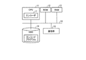
図2にサーバ装置1のブロック図を示す。図2に示すように、サーバ装置1は、通常のパーソナルコンピュータ装置と同様のハードウェア構成を有している。すなわち、サーバ装置1は、CPU11、ROM12、RAM13、HDD(ハードディスクドライブ)14、および、通信部15を備える。CPU11〜通信部15は、バスライン16を介して相互に接続されている。CPUは、「Central Processing Unit」の略記である。ROMは、「Read Only Memory」の略記である。RAMは、「Random Access Memory」の略記である。
FIG. 2 shows a block diagram of the
HDD14には、映像ストリームをエンコードするためのエンコードプログラムが記憶されている。CPU11は、エンコードプログラムに従って動作することで、エンコード部の一例であるエンコーダ17として機能し、映像ストリームをエンコード処理して配信する。なお、エンコードプログラムは、ROM12またはRAM13に記憶されていてもよい。
The
図3にクライアント装置2のブロック図を示す。図3に示すように、クライアント装置2は、通常のパーソナルコンピュータ装置と同様のハードウェア構成を有している。すなわち、クライアント装置2は、CPU21、ROM22、RAM23、HDD(ハードディスクドライブ)24、および、通信部25を備える。CPU21〜通信部25は、バスライン26を介して相互に接続されている。通信部25は、受信部の一例である。
FIG. 3 shows a block diagram of the
HDD24には、サーバ装置1から受信した映像ストリームをデコードするためのデコードプログラムが記憶されている。CPU21は、デコードプログラムに従って動作することで、デコード部の一例であるデコーダ27として機能し、サーバ装置1から受信した映像ストリームをデコード処理する。なお、デコードプログラムは、ROM22またはRAM23に記憶されていてもよい。
The HDD 24 stores a decoding program for decoding the video stream received from the
この例では、エンコーダ17およびデコーダ27はソフトウェア的に実現されるものとして説明を進める。しかし、エンコーダ17およびデコーダ27のうち、全部またはいずれか一つをハードウェアで実現してもよい。
In this example, the description will proceed assuming that the
また、エンコードプログラムおよびデコードプログラムは、インストール可能な形式または実行可能な形式のファイルでCD−ROM、フレキシブルディスク(FD)などのコンピュータ装置で読み取り可能な記録媒体に記録して提供してもよい。また、エンコードプログラムおよびデコードプログラムは、CD−R、DVD、ブルーレイディスク(登録商標)、半導体メモリ等のコンピュータ装置で読み取り可能な記録媒体に記録して提供してもよい。DVDは、「Digital Versatile Disk」の略記である。また、エンコードプログラムおよびデコードプログラムは、インターネット等のネットワーク経由でインストールするかたちで提供してもよい。また、エンコードプログラムおよびデコードプログラムは、機器内のROM等に予め組み込んで提供してもよい。 The encoding program and the decoding program may be provided by being recorded in a computer-readable recording medium such as a CD-ROM or a flexible disk (FD) in an installable or executable format file. The encoding program and the decoding program may be provided by being recorded on a recording medium readable by a computer device such as a CD-R, a DVD, a Blu-ray disc (registered trademark), or a semiconductor memory. DVD is an abbreviation for “Digital Versatile Disk”. Further, the encoding program and the decoding program may be provided by being installed via a network such as the Internet. The encoding program and the decoding program may be provided by being incorporated in advance in a ROM or the like in the device.
次に、第1の実施の形態のストリーミングシステムにおける映像ストリームの送受信動作を説明する。まず、サーバ装置1のエンコーダ17は、所定の時点で区切った映像ソースを、それぞれ異なるビットレートとなるようにエンコード処理することで、各ビットレートのGOPを生成する。一例ではあるが、エンコーダ17は、高ビットレート、低ビットレート、および、高ビットレートと低ビットレートの中間のビットレート(中間ビットレート)のGOPをそれぞれ生成する。そして、エンコーダ17は、同一の時点の区切られた各ビットレートのGOPをまとめて、一つの映像ストリームを生成し、HDD14に記憶する。高ビットレートのGOPは、第1のビットレートの第1の画像群の一例である。また、中間のビットレートおよび低ビットレートのGOPは、第2のビットレートの第2の画像群の一例である。各映像ストリームの各GOPは、それぞれ独立再生可能となっている。
Next, a video stream transmission / reception operation in the streaming system according to the first embodiment will be described. First, the
なお、この例では、生成された各映像ストリームは、HDD14に記憶されることとしたが、例えばライブ映像のようにリアルタイムで配信する場合は、リアルタイムでエンコードされ、クライアント装置2側に配信される。
In this example, each generated video stream is stored in the
また、この例では、エンコーダ17は、同一の時点の区切られた各ビットレートのGOPをまとめて、一つの映像ストリームを生成することとした。しかし、エンコーダ17が、一つの映像ストリームに一つのビットレートのGOPのみを含むように、映像ソースをエンコードしてもよい。この場合、エンコーダ17は、同一の時点で区切った映像ソースから、高ビットレートのGOP、中間ビットレートのGOP、および、低ビットレートのGOPをエンコードする。そして、エンコーダ17は、高ビットレートのGOPのみを含む第1の映像ストリーム、中間ビットレートのGOPのみを含む第2の映像ストリーム、および、低ビットレートのGOPのみを含む第3の映像ストリームを生成する。
In this example, the
また、エンコーダ17は、各映像ストリームのファイル内に、Pピクチャのデコード時に参照する基準画像が含まれている映像ストリームを示す参照情報を挿入する。または、エンコーダ17は、Pピクチャのデコード時に参照する基準画像が含まれている映像ストリームを示す再生制御ファイルを、各映像ストリームに付加する。デコーダ27は、参照情報または再生制御ファイルで指定される映像ストリームを参照し、上述の各実施の形態で説明したように、Pピクチャをデコードする。これにより、上述の各実施の形態と同様の効果を得ることができる。
In addition, the
次に、クライアント装置2のデコーダ27は、映像ストリームの通信帯域を計測している。デコーダ27は、計測した通信帯域に応じて、受信するGOPのビットレートを選択する。そして、デコーダ27は、サーバ装置1に対して、選択したビットレートのGOPの映像ストリームの配信要求を行う。
Next, the
具体的には、デコーダ27は、通信帯域に余裕があるときには、高ビットレートのGOPの映像ストリームの配信要求を行う。これに対して、通信帯域に余裕が無いときには、デコーダ27は、低ビットレートのGOPの映像ストリームの配信要求を行う。また、デコーダ27は、通信帯域に多少の余裕があるときには、中間ビットレートのGOPの映像ストリームの配信要求を行う。
Specifically, when there is a margin in the communication band, the
デコーダ27は、選択したビットレートのGOPの映像ストリームを、サーバ装置1から受信する。そして、デコーダ27は、受信した映像ストリームをデコード処理し、モニタ装置等に表示する。または、デコーダ27は、受信した映像ストリームを記録装置に出力して記録媒体に記録する。
The
なお、この例は、クライアント装置2側でネットワークの通信帯域を計測し、計測した通信帯域に対応するビットレートのGOPの配信要求を、サーバ装置1に行うこととした。しかし、サーバ装置1が、ネットワークの帯域を計測して、送信するGOPのビットレートを切り替えて配信してもよい。このための具体的な手法としては、アダプティブストリーミングのストリーミング切り替え手法では、ストリーム指定方法を拡張し、各画像への参照を定義することで実現が可能である。
In this example, the network communication bandwidth is measured on the
また、クライアント装置2またはサーバ装置1以外の何らかの装置、ルータ装置、または専用測定装置等でネットワークの通信帯域を計測し、クライアント装置2またはサーバ装置1が計測結果を受信して、GOPのビットレートを切り替えるための情報として用いてもよい。また,クライアント装置2で計測したネットワークの通信帯域の計測結果をサーバ装置1が受信し、サーバ装置1が、GOPのビットレートを切り替えてもよい。または、サーバ装置1が計測した通信帯域の計測結果をクライアント装置2が受信し、クライアント装置2が、GOPのビットレートを切り替えてもよい。
Further, the network communication band is measured by some device other than the
次に、第1の実施の形態のストリーミングシステムにおける映像ストリームのエンコード動作およびデコード動作の詳細を説明する。まず、図4のフローチャートに、サーバ装置1のエンコード動作の流れを示す。サーバ装置1のCPU11は、映像ストリームのエンコード時になると、エンコーダ17として機能する。エンコーダ17は、ステップS1において、所定のビットレートの映像ストリームの画像内符号化画像(Iピクチャ)を、他の画像間差分符号化画像(Pピクチャ)で参照するように、各映像ストリームにIピクチャの参照情報を挿入して、所定のエンコード処理を行う。
Next, details of video stream encoding and decoding operations in the streaming system of the first embodiment will be described. First, the flow of the encoding operation of the
なお、Iピクチャは、他の画像を参照しないでデコードできるように画像内で符号化された画像である。また、Pピクチャは、直前のフレームから変化した差分のデータのみを符号化した画像である。このPピクチャと共に、または、Pピクチャの代わりにBピクチャを用いてもよい。Bピクチャは、前後の画像に対する変化差分のデータのみを符号化した画像である。 An I picture is an image encoded in an image so that it can be decoded without referring to another image. A P picture is an image obtained by encoding only difference data changed from the immediately preceding frame. A B picture may be used together with the P picture or instead of the P picture. A B picture is an image obtained by encoding only change difference data with respect to previous and subsequent images.
図5および図6に、エンコーダ17のエンコード動作の模式図を示す。エンコーダ17は、MPEG方式に従って、映像ソースのエンコード処理を行う。具体的には、エンコーダ17は、最初の数秒の映像ソースをエンコード処理することで、第1の映像ストリームを生成し、最初の数秒の映像ソースに続く数秒の映像ソースをエンコード処理することで、第2の映像ストリームを生成する等のように、所定時間毎に映像ソースをエンコード処理して、連続する映像ストリームを生成する。
5 and 6 are schematic diagrams of the encoding operation of the
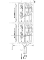
エンコーダ17は、図5および図6に示すように高ビットレートのGOP、中間ビットレートのGOP、および、低ビットレートのGOPを含むように各映像ストリームを生成する。GOPは、「Group Of Pictures」の略記である。図5に示す「H1」の符号は、第1の映像ストリームに含まれる高ビットレートのGOPを示している。同様に、「H2」の符号は、第2の映像ストリームに含まれる高ビットレートのGOPを示している。また、「M1」の符号は、第1の映像ストリームに含まれる中間ビットレートのGOPを示している。同様に、「M2」の符号は、第2の映像ストリームに含まれる中間ビットレートのGOPを示している。また、「L1」の符号は、第1の映像ストリームに含まれる低ビットレートのGOPを示している。同様に、「L2」の符号は、第2の映像ストリームに含まれる低ビットレートのGOPを示している。
As shown in FIGS. 5 and 6, the
図5および図6に示す例の場合、エンコーダ17は、各ビットレートのGOPのPピクチャ(P−pic)をデコードする際に参照する画像として、高ビットレートのGOPのIピクチャ(I−pic)を指定してエンコード処理を行う。具体的には、エンコーダ17は、各GOPのヘッダ等に、Pピクチャをデコードする際に参照するIピクチャを指定する参照情報を挿入する。なお、エンコーダ17は、参照するIピクチャを示す再生制御ファイルを生成して、各GOPまたは対応する映像ストリームに付加してもよい。
In the example shown in FIGS. 5 and 6, the
エンコーダ17により生成された各映像ストリームは、図4のフローチャートのステップS2において、CPU11が通信部15を通信制御して、各クライアント装置2に配信される。これにより、図4のフローチャートの処理が終了する。
Each video stream generated by the
次に、図7のフローチャートに、クライアント装置2における、受信した映像ストリームのデコード処理の流れを示す。クライアント装置2のCPU21は、HDD24に記憶されているデコードプログラムに従ってデコーダ27として機能し、サーバ装置1から受信した映像ストリームをデコード処理する。
Next, the flowchart of FIG. 7 shows the flow of decoding processing of the received video stream in the
具体的には、サーバ装置1から映像ストリームを受信すると、デコーダ27は、図7のフローチャートのステップS11において、上述の参照情報または再生制御ファイルで指定されるIピクチャをデコードする。また、デコーダ27は、ユーザに選択されたビットレートのGOPのPピクチャを、デコードしたIピクチャを用いてデコードする。
Specifically, when the video stream is received from the
図5および図6は、デコードされたIピクチャを用いて、各ビットレートのGOPのPピクチャがデコードされる様子を示している。なお、図5および図6の例は、高ビットレートのGOPのIピクチャが参照情報で指定されている例である。この場合は、高ビットレートのGOPのIピクチャで他のPピクチャがデコードされる。しかし、例えば中間ビットレートのGOPのIピクチャを参照情報で指定してもよい。この場合は、中間ビットレートのGOPのIピクチャで他のPピクチャがデコードされる。さらに、低ビットレートのGOPのIピクチャを参照情報で指定してもよい。この場合は、低ビットレートのGOPのIピクチャで他のPピクチャがデコードされる。 FIG. 5 and FIG. 6 show how a P picture of a GOP at each bit rate is decoded using the decoded I picture. The examples of FIGS. 5 and 6 are examples in which an I picture of a GOP with a high bit rate is specified by reference information. In this case, another P picture is decoded with an I picture of a GOP with a high bit rate. However, for example, an I-picture of a GOP having an intermediate bit rate may be specified by reference information. In this case, another P picture is decoded with the I picture of the GOP having the intermediate bit rate. Further, an I picture of a GOP with a low bit rate may be specified by reference information. In this case, another P picture is decoded with an I picture of a GOP with a low bit rate.
このようにデコードされた映像ストリームは、ステップS12において、モニタ装置に出力されることで表示される。これにより、図7のフローチャートのデコード処理が終了する。なお、映像ストリームを、記録装置に出力し、記録媒体に記録してもよい。この場合、映像ストリームは、デコードせずに記録してもよい。また、通信レートに合わせた各ビットレートで受信したデータを、そのまま記録してもよいし、各映像ストリームを統合結合することで再構成した後に記録してもよい。 The video stream decoded in this way is displayed by being output to the monitor device in step S12. Thereby, the decoding process of the flowchart of FIG. 7 is completed. Note that the video stream may be output to a recording device and recorded on a recording medium. In this case, the video stream may be recorded without being decoded. Further, data received at each bit rate in accordance with the communication rate may be recorded as it is, or may be recorded after being reconfigured by integrating and combining the video streams.
以上の説明から明らかなように、第1の実施の形態のストリーミングシステムは、各映像ストリーム毎に、いずれかのビットレートのIピクチャを、Pピクチャをデコードする際に用いる画像として指定してエンコード処理する。そして、デコードする際に、指定されているIピクチャをデコードすると共に、デコードしたIピクチャを用いて、ユーザに指定されたGOPのPピクチャをデコードする。 As is apparent from the above description, the streaming system of the first embodiment specifies and encodes an I picture of any bit rate as an image used when decoding a P picture for each video stream. To process. At the time of decoding, the designated I picture is decoded, and the decoded I picture is used to decode the P picture of the GOP designated by the user.
通常、マルチエンコード方式のアダプティブストリーミングシステムにおいては、エンコーダにより映像ソースを異なる複数のビットレートの映像ストリームに変換する際に生成される映像ストリームは、全て独立した映像ストリームとなっている。このため、映像ストリームの切り替えが可能となるタイミングは、映像ストリーム同士でランダムアクセスが可能となるタイミング(GOPの先頭のIピクチャのタイミング)に限られていた。 In general, in a multi-encoding adaptive streaming system, the video streams generated when the video source is converted into video streams of different bit rates by the encoder are all independent video streams. For this reason, the timing at which video streams can be switched is limited to the timing at which random access is possible between video streams (the timing of the first I picture of a GOP).
しかし、第1の実施の形態のストリーミングシステムの場合、各GOPのPピクチャは、予め指定されているIピクチャを用いてデコードされる。このため、図5のKT1〜KT4に示すように、Iピクチャのタイミング、および、各GOPの全てのPピクチャのタイミングで、映像ストリームの切り替えを可能とすることができる。このため、マルチエンコード方式のアダプティブストリーミングシステムにおいて、映像ストリームの切り替えが可能なタイミングを増やすことができる。 However, in the case of the streaming system of the first embodiment, the P picture of each GOP is decoded using a pre-designated I picture. Therefore, as shown in KT1 to KT4 in FIG. 5, it is possible to switch the video stream at the timing of the I picture and the timing of all the P pictures of each GOP. Therefore, it is possible to increase the timing at which video streams can be switched in a multi-encoding adaptive streaming system.
また、第1の実施の形態のストリーミングシステムは、状況の悪いネットワークで映像伝送する際も、安易に低ビットレートの映像ストリームを取得して映像品質の低下を防止できる。また、映像ストリームの再生時間内で全体の取得完了を見越した長めのバッファリング時間を取ることによる遅延を防止することができる。 In addition, the streaming system of the first embodiment can easily acquire a low bit rate video stream and prevent deterioration in video quality even when video transmission is performed over a poor network. Further, it is possible to prevent a delay caused by taking a longer buffering time in anticipation of the completion of the entire acquisition within the playback time of the video stream.
[第2の実施の形態]
次に、第2の実施の形態のストリーミングシステムの説明をする。上述の第1の実施の形態のストリーミングシステムは、いずれかのGOPのIピクチャを、他のPピクチャのデコードの際に参照するものであった。これに対して、第2の実施の形態のストリーミングシステムは、先頭のPピクチャをデコードする際に、いずれかのGOPのIピクチャを参照してデコードし、以後、後続するPピクチャを、デコード済みの直前のPピクチャを参照してデコードするようにしたものである。
[Second Embodiment]
Next, the streaming system according to the second embodiment will be described. The streaming system according to the first embodiment described above refers to the I picture of any GOP when decoding another P picture. On the other hand, when the first P picture is decoded, the streaming system of the second embodiment refers to the I picture of any GOP and decodes the subsequent P picture. The P picture immediately before is decoded with reference to the P picture.
図8は、このような第2の実施の形態のストリーミングシステムのエンコード動作を示す模式図である。この例の場合、エンコーダ17は、上述の参照情報または再生制御ファイルにより、各ビットレートのGOPの先頭のPピクチャをデコードする際に参照する画像として、高ビットレートのGOPのIピクチャを指定して映像ソースをエンコードする。また、エンコーダ17は、上述の参照情報または再生制御ファイルにより、各ビットレートのGOPの第2番目以降のPピクチャをデコードする際に参照する画像として、直前のPピクチャを指定して映像ソースをエンコードする。
FIG. 8 is a schematic diagram showing an encoding operation of the streaming system according to the second embodiment. In this example, the
図8に示す例の場合、Iピクチャは、高ビットレートのGOPに生成されている。このため、デコーダ27は、高ビットレートのGOPのIピクチャを参照して、各ビットレートのGOPの先頭のPピクチャをデコードする。また、デコーダ27は、Iピクチャを用いてデコードされた先頭のPピクチャを参照して、第2番目のPピクチャをデコードする。さらに、デコーダ27は、先頭のPピクチャを参照してデコードされた第2番目のPピクチャを参照して、第3番目のPピクチャをデコードする。すなわち、デコーダ27は、デコードしようとしているPピクチャの直前に位置するデコード済みのPピクチャを用いて、第2番目以降のPピクチャをデコードする。
In the case of the example shown in FIG. 8, the I picture is generated in a GOP with a high bit rate. Therefore, the
これにより、第2の実施の形態のストリーミングシステムは、図8に示すようにIピクチャのタイミング、および、各GOPのデコード済みのPピクチャのタイミングで、映像ストリームの切り替えを可能とすることができる。このため、第2の実施の形態のストリーミングシステムは、映像ストリームの切り替えが可能なタイミングを増やすことができる他、上述の第1の実施の形態と同様の効果を得ることができる。 Accordingly, the streaming system according to the second embodiment can switch the video stream at the timing of the I picture and the decoded P picture of each GOP as shown in FIG. . For this reason, the streaming system of the second embodiment can increase the timing at which video streams can be switched, and can obtain the same effects as those of the first embodiment described above.
[第3の実施の形態]
次に、第3の実施の形態のストリーミングシステムの説明をする。上述の第2の実施の形態のストリーミングシステムは、先頭のPピクチャをデコードする際に、いずれかのGOPのIピクチャを参照してデコードし、以後、後続するPピクチャを、デコードされた直前のPピクチャを参照してデコードするようにしたものであった。これに対して、第3の実施の形態のストリーミングシステムは、デコードされた直前のPピクチャを参照して後続するPピクチャをデコードする際に、Iピクチャを含むGOPのPピクチャを参照してデコードするPピクチャを含めたものである。
[Third Embodiment]
Next, the streaming system according to the third embodiment will be described. When the first P picture is decoded, the streaming system of the second embodiment described above refers to the I picture of any GOP and decodes the subsequent P picture immediately before the decoding. Decoding was performed with reference to the P picture. In contrast, the streaming system according to the third embodiment refers to the P picture of the GOP including the I picture when the subsequent P picture is decoded with reference to the decoded previous P picture. The P picture is included.
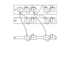
図9は、このような第3の実施の形態のストリーミングシステムのエンコード動作を示す模式図である。この例の場合、エンコーダ17は、上述の参照情報または再生制御ファイルにより、各ビットレートのGOPの先頭のPピクチャをデコードする際に参照する画像として、高ビットレートのGOPのIピクチャを指定して映像ソースをエンコードする。また、エンコーダ17は、上述の参照情報または再生制御ファイルにより、Iピクチャを含むGOPの第2番目以降のPピクチャをデコードする際に参照する画像として、直前のPピクチャを指定して映像ソースをエンコードする。
FIG. 9 is a schematic diagram showing the encoding operation of the streaming system of the third embodiment. In this example, the
また、エンコーダ17は、上述の参照情報または再生制御ファイルにより、Iピクチャを含まないビットレートのGOPの第2番目のPピクチャをデコードする際に参照する画像として、直前のPピクチャを指定して映像ソースをエンコードする。また、エンコーダ17は、上述の参照情報または再生制御ファイルにより、Iピクチャを含まないビットレートのGOPの第3番目のPピクチャをデコードする際に参照する画像として、高ビットレートのGOPの第2番目のPピクチャを指定して映像ソースをエンコードする。また、エンコーダ17は、上述の参照情報または再生制御ファイルにより、Iピクチャを含まないビットレートのGOPの第4番目のPピクチャをデコードする際に参照する画像として、直前の第3番目のPピクチャを指定して映像ソースをエンコードする。
Also, the
図9に示す例の場合、Iピクチャは、高ビットレートのGOPに生成されている。このため、デコーダ27は、高ビットレートのGOPのIピクチャを参照して、各ビットレートのGOPの先頭のPピクチャをデコードする。また、デコーダ27は、Iピクチャを含むGOPの各Pピクチャを、直前のPピクチャを用いてデコードする。
In the case of the example shown in FIG. 9, the I picture is generated in a high bit rate GOP. Therefore, the
また、デコーダ27は、Iピクチャを含まないGOPの第2番目のPピクチャを、Iピクチャを用いてデコードされた先頭のPピクチャを参照してデコードする。また、デコーダ27は、Iピクチャを含まないGOPの第3番目のPピクチャを、Iピクチャを含む高ビットレートのGOPの第2番目のPピクチャを参照してデコードする。さらに、デコーダ27は、Iピクチャを含まないGOPの第4番目のPピクチャを、直前の第3番目のPピクチャを参照してデコードする。すなわち、デコーダ27は、所定数のPピクチャのデコード処理を行う毎に、Iピクチャを含むGOPのIピクチャまたはPピクチャを参照してデコード処理を行う。
The
これにより、第3の実施の形態のストリーミングシステムは、図9に示すIピクチャのタイミング、および、各GOPの先頭のPピクチャのタイミングで、映像ストリームの切り替えを可能とすることができる等、上述の第2の実施の形態と同様の効果を得ることができる。第3の実施の形態のストリーミングシステムの場合、切り替えは、参照元のIピクチャ、または、Pピクチャを含む映像ストリームから参照先の映像ストリームの一方向のみ可能となる。しかし、第3の実施の形態のストリーミングシステムは、参照先が直前のフレームとなるため、参照先のフレームのデータ量を削減することができる。 As a result, the streaming system according to the third embodiment can switch the video stream at the timing of the I picture shown in FIG. 9 and the timing of the first P picture of each GOP. The same effect as in the second embodiment can be obtained. In the streaming system of the third embodiment, switching can be performed only in one direction from a video stream including a reference source I picture or P picture to a reference destination video stream. However, in the streaming system of the third embodiment, since the reference destination is the immediately preceding frame, the data amount of the reference destination frame can be reduced.
[第4の実施の形態]
次に、第4の実施の形態のストリーミングシステムの説明をする。第4の実施の形態のストリーミングシステムは、上述の複数の異なるビットレートのGOPと共に、画像の一部を高画質化した画像を含むGOPで各映像ストリームを構成したものである。
[Fourth Embodiment]
Next, a streaming system according to a fourth embodiment will be described. In the streaming system according to the fourth embodiment, each video stream is configured by a GOP including a plurality of GOPs having different bit rates as described above and an image obtained by improving the image quality of a part of the image.
第4の実施の形態のストリーミングシステムの場合、サーバ装置1のエンコーダ17は、図10に示すように、複数の異なるビットレートのGOPと共に、部分的に高画質化したビットレートのGOPで各映像ストリームを構成するように、映像ソースをエンコードする。すなわち、図10に示す「H」、「M」、「L」、「P」は、それぞれ高ビットレートのGOP、中間ビットレートのGOP、低ビットレートのGOP、部分的に高画質化された低ビットレートのGOPを示している。すなわち、部分的に高画質化された低ビットレートのGOPは、低画質の画像のGOPである。そして、低画質の画像のうち、一部または複数の部分が高画質の画像となっている。また、「H1」、「M1」、「L1」、「P1」は、第1の映像ストリームに含まれるGOPを示している。同様に、「H2」、「M2」、「L2」、「P2」は、第2の映像ストリームに含まれるGOPを、「H3」、「M3」、「L3」、「P3」は、第3の映像ストリームに含まれるGOPを示している。
In the case of the streaming system according to the fourth embodiment, the
また、各映像ストリームの各GOPは、第1の実施の形態〜第3の実施の形態で説明した構成となっている。すなわち、各映像ストリームの各GOPは、Pピクチャのデコードは、いずれかのビットレートのIピクチャを参照してデコードする構成となっている。または、各映像ストリームの各GOPは、いずれかのビットレートのIピクチャを参照してデコード済みのPピクチャを参照してデコードする構成となっている。 Each GOP of each video stream has the configuration described in the first to third embodiments. That is, each GOP of each video stream is configured to decode a P picture with reference to an I picture of any bit rate. Alternatively, each GOP of each video stream is configured to refer to an I picture at any bit rate and decode it with reference to a decoded P picture.
なお、この例では、低ビットレートのGOPに、高画質化された部分的な画像を含ませることとしたが、中間ビットレートのGOPまたは高ビットレートのGOPに、高画質化された部分的な画像を含ませてもよい。 In this example, a low-bit-rate GOP includes a partial image with high image quality. However, an intermediate-bit-rate GOP or a high-bit-rate GOP has a partial image with high image quality. Various images may be included.
クライアント装置2においては、デコーダ27が、映像ストリームの受信中に通信帯域を計測する。そして、デコーダ27は、計測した通信帯域に応じて、次に受信するビットレートを選択して映像ストリームを受信する。
In the
具体的には、デコーダ27は、通信帯域に余裕があるときには、高ビットレートのGOPを選択して受信しデコードする。これに対して、通信帯域に余裕が無いときには、デコーダ27は、低ビットレートのGOPを選択してデコードする。さらに、通信帯域に余裕が無いときにおいて、高画質な画像を得たい場合には、部分的に高画質化された低ビットレートのGOPを選択して受信しデコードする。部分的に高画質化された低ビットレートのGOPを選択することで、低ビットレートのGOPをスムーズに受信しながら、部分的ではあるが、所望の部分が高画質化された画像を得ることができる。
Specifically, the
このような第4の実施の形態のストリーミングシステムは、部分的に高画質化したGOPを取り扱うストリーミングシステムを、アダプティブストリーミングによる映像ストリームの切り替えで実現する際に、生成する映像データの組み合わせを減らし応答遅延を減らすことができる他、上述の各実施の形態と同様の効果を得ることができる。 Such a streaming system according to the fourth embodiment responds by reducing the number of combinations of video data to be generated when realizing a streaming system that handles a partially-enhanced GOP by switching video streams by adaptive streaming. In addition to reducing the delay, the same effects as those of the above-described embodiments can be obtained.
[第5の実施の形態]
次に、第5の実施の形態のストリーミングシステムの説明をする。高ビットレートの画像であっても、部分的にズームアップさせると、ぼやけた画像となる。このため、第5の実施の形態のストリーミングシステムでは、全体画像から選択された部分的な高画質画像を配信することで、ユーザが全体画像中の所望の部分を高画質で見ることができるようにしたものである。
[Fifth Embodiment]
Next, a streaming system according to a fifth embodiment will be described. Even a high bit rate image is blurred when partially zoomed up. For this reason, in the streaming system according to the fifth embodiment, by distributing a partial high-quality image selected from the entire image, the user can view a desired portion in the entire image with high image quality. It is a thing.
図11は、第5の実施の形態のストリーミングシステムで用いられる画像の生成の仕方を説明するための図である。第5の実施の形態のストリーミングシステムの場合、サーバ装置1のエンコーダ17は、図11に示すように、例えば横×縦が3840画素×2160画素の広角かつ高解像度の映像ソースを用いる。そして、エンコーダ17は、広角かつ高解像度の映像ソースを、横×縦を1280画素×720画素に縮小した縮小画像のGOPを生成する。また、エンコーダ17は、広角かつ高解像度の映像ソースを、所定の画素数のトリミング領域に分割する。そして、エンコーダ17は、各トリミング領域のGOPを生成する。図11に示す第1のトリミング領域〜第nのトリミング領域は、それぞれ広角かつ高解像度の映像ソースから分割された所定の画素数のトリミング領域を示している。第nのトリミング領域の「n」は、自然数である。
FIG. 11 is a diagram for explaining a method of generating an image used in the streaming system according to the fifth embodiment. In the case of the streaming system of the fifth embodiment, the
また、第5の実施の形態のストリーミングシステムの場合、各トリミング領域のGOPにおいてPピクチャをデコードする際、第1の実施の形態で説明したように、例えば縮小画像のGOPのIピクチャを参照する構成となっている(図5および図6参照)。または、第5の実施の形態のストリーミングシステムの場合、第2の実施の形態で説明したように、各トリミング領域のGOPの先頭のPピクチャをデコードする際、縮小画像のGOPのIピクチャを参照してデコードし、以後、後続するPピクチャを、デコードされた直前のPピクチャを参照してデコードする構成となっている(図8参照)。または、第5の実施の形態のストリーミングシステムの場合、第3の実施の形態で説明したように、各トリミング領域のGOPにおいてPピクチャをデコードする際、縮小画像のGOPのIピクチャまたは縮小画像のGOPのデコード済みのPピクチャを用いて、各トリミング領域のGOPのPピクチャをデコードする構成となっている(図9参照)。 In the streaming system according to the fifth embodiment, when the P picture is decoded in the GOP of each trimming area, for example, as described in the first embodiment, the I picture of the GOP of the reduced image is referred to. It has a configuration (see FIGS. 5 and 6). Alternatively, in the case of the streaming system of the fifth embodiment, as described in the second embodiment, when decoding the first P picture of the GOP in each trimming area, reference is made to the I picture of the GOP of the reduced image The subsequent P picture is decoded with reference to the immediately preceding decoded P picture (see FIG. 8). Alternatively, in the case of the streaming system of the fifth embodiment, as described in the third embodiment, when the P picture is decoded in the GOP of each trimming region, the I picture of the GOP of the reduced image or the reduced image The GOP P picture in each trimming area is decoded using the GOP decoded P picture (see FIG. 9).
次に、図12は、第5の実施の形態のストリーミングシステムにおける映像ストリームの配信形態を説明するための図である。第5の実施の形態のストリーミングシステムの場合、ユーザは、クライアント装置2において、縮小化された全体画像を受信する。クライアント装置2のデコーダ27は、受信した全体画像をデコードしてモニタ装置に表示する。次に、クライアント装置2は、ユーザにより、全体画像中の所望の領域が指定されると、デコーダ27が、サーバ装置1に対して、ユーザに指定された指定領域の画像の送信要求を行う。サーバ装置1は、送信要求に対応する指定領域の高解像度のズーム画像をエンコードしてクライアント装置2に送信する。図11に示す第1のトリミング領域〜第nのトリミング領域が、ユーザにより指定された各指定領域の高解像度のズーム画像(トリミング領域のGOP)を示している。デコーダ27は、送信された高解像度のズーム画像を受信してデコードし、モニタ装置に表示する。これにより、全体画像中の所望の部分に対応する、ボケが発生していない高画質な部分的な画像を見ることができる。
Next, FIG. 12 is a diagram for explaining a video stream distribution form in the streaming system according to the fifth embodiment. In the case of the streaming system of the fifth embodiment, the user receives the reduced whole image at the
なお、他の部分の高画質なズーム画像を見る場合、ユーザは、縮小化された全体画像から所望の部分を再度指定する。これにより、上述と同様に、ユーザに指定された部分的な高画質なズーム画像がサーバ装置1から配信される。そして、サーバ装置1から配信されたズーム画像をデコードすることで、モニタ装置を介して見ることができる。
Note that when viewing a high-quality zoom image of another portion, the user designates a desired portion again from the reduced overall image. Accordingly, as described above, a partial high-quality zoom image designated by the user is distributed from the
このような第5の実施の形態のストリーミングシステムも、上述の第4の実施の形態と同様に、部分的に高画質化したズーム画像を取り扱うストリーミングシステムを、アダプティブストリーミングによる映像ストリームの切り替えで実現する際に、生成する映像データの組み合わせを減らし応答遅延を減らすことができる他、上述の各実施の形態と同様の効果を得ることができる。 The streaming system according to the fifth embodiment as well as the fourth embodiment described above realizes a streaming system that handles a zoom image partially improved in image quality by switching video streams by adaptive streaming. In doing so, in addition to reducing the number of combinations of video data to be generated and reducing response delay, the same effects as those of the above-described embodiments can be obtained.
なお、第5の実施の形態の場合、例えば横×縦が3840画素×2160画素の広角かつ高解像度の映像ソースを、横×縦を1280画素×720画素に縮小した全体画像表示用のGOPを生成した。そして、第5の実施の形態の場合、横×縦を1280画素×720画素に縮小した全体画像表示用のGOPのIピクチャ(Pピクチャの場合もある)を基準画像として、各トリミング領域のPピクチャをデコードした。 In the case of the fifth embodiment, for example, a wide-angle and high-resolution video source having horizontal × vertical of 3840 pixels × 2160 pixels and a GOP for displaying an entire image in which horizontal × vertical is reduced to 1280 pixels × 720 pixels are used. Generated. In the case of the fifth embodiment, the P image of each trimming area is defined by using the I picture (which may be a P picture) of the GOP for displaying the entire image, which is reduced to 1280 pixels × 720 pixels in the horizontal × vertical direction, as a reference image. The picture was decoded.
しかし、デコード時に基準画像として参照されるIピクチャを含むGOPのみ、元の解像度のままとし、Iピクチャを含むGOPに続く各GOPは、縮小画像を用いて生成したGOPとしてもよい。この場合、Iピクチャを含むGOPを、横×縦が3840画素×2160画素の広角かつ高解像度の映像ソースで生成する。また、横×縦が3840画素×2160画素の映像ソースを、横×縦が1280画素×720画素に縮小した映像ソースで、Iピクチャを含むGOPに続く各トリミング領域のGOPを生成する。 However, only the GOP including the I picture that is referred to as the standard image at the time of decoding may be kept at the original resolution, and each GOP following the GOP including the I picture may be a GOP generated using the reduced image. In this case, a GOP including an I picture is generated with a wide-angle and high-resolution video source with horizontal × vertical of 3840 pixels × 2160 pixels. Further, a GOP of each trimming region following the GOP including the I picture is generated by reducing the horizontal x vertical video source of 3840 pixels x 2160 pixels to the horizontal x vertical of 1280 pixels x 720 pixels.
これにより、各トリミング領域のGOPの各Pピクチャは、横×縦が3840画素×2160画素の広角かつ高解像度の映像ソースで生成されたIピクチャ(Pピクチャの場合もある)を参照してデコードされる。このため、トリミング領域等の高画質画像(ボケの生じていない画像)を得ることができる。なお、ネットワークの通信帯域に余裕が無いことが明白な場合、Iピクチャを含む最初のGOPは、トリミング領域と同一の一部分のみに対応するGOPを転送するように、クライアント装置2が送信要求、または、サーバ装置1が配信してもよい。
As a result, each P picture of the GOP in each trimming area is decoded with reference to an I picture (which may be a P picture) generated with a wide-angle and high-resolution video source having horizontal × vertical of 3840 pixels × 2160 pixels. Is done. For this reason, it is possible to obtain a high-quality image (an image with no blur) such as a trimming region. If it is clear that there is no room in the communication band of the network, the first GOP including the I picture is requested by the
最後に、以上説明した各実施の形態は、例として提示したものであり、発明の範囲を限定することは意図していない。これら新規な各実施の形態は、その他の様々な形態で実施可能である。また、これら新規な各実施の形態は、発明の要旨を逸脱しない範囲で、種々の省略、置き換え、変更が可能である。そして、各実施の形態およびその変形は、発明の範囲や要旨に含まれると共に、特許請求の範囲に記載された発明に対して均等の範囲に含まれるものである。 Finally, each embodiment described above is provided as an example, and is not intended to limit the scope of the invention. Each of these novel embodiments can be implemented in various other forms. Each of these novel embodiments can be variously omitted, replaced, and changed without departing from the gist of the invention. Each embodiment and its modifications are included in the scope and gist of the invention, and are also included in the scope equivalent to the invention described in the claims.
1 サーバ装置
2 クライアント装置
3 ネットワーク
11 CPU
12 ROM
13 RAM
14 HDD
15 通信部
16 バスライン
17 エンコーダ
21 CPU
22 ROM
23 RAM
24 HDD
25 通信部
26 バスライン
27 デコーダ
1
12 ROM
13 RAM
14 HDD
15
22 ROM
23 RAM
24 HDD
25
Claims (9)
前記第1の画像群と再生タイミングが同期した前記第2の画像群は、低画質の画像群であり、一部または複数の部分が高画質化された画像を含む画像群であること
を特徴とするエンコード装置。 A first image group consisting of a plurality of images encoded at a first bit rate so as to include an intra-image encoded image, and the intra-image encoded image as a reference image for decoding an inter-image difference encoded image A video stream including at least a second image group including a plurality of images that are associated with each other and encoded at a second bit rate that is different from the first bit rate, the reproduction timing of which is synchronized with the first image group. Has an encoding part to generate ,
The second image group whose reproduction timing is synchronized with the first image group is a low-quality image group, and is an image group including an image in which a part or a plurality of parts are improved in image quality.
An encoding device characterized by .
を特徴とする請求項1に記載のエンコード装置。 The encoding unit inserts reference information indicating the associated standard image into a file of the video stream, or adds a playback control file indicating the associated standard image to the video stream. The encoding apparatus according to claim 1, wherein the output is added and output.
前記第2のビットレートの前記第2の画像群は、前記基準画像を用いてデコードされる、前記画像間差分符号化画像のみを含むこと
を特徴とする請求項1または請求項2に記載のエンコード装置。 The first image group of the first bit rate including the reference image includes the intra-image encoded image serving as the reference image, and the inter-image difference encoded image,
The said 2nd image group of a said 2nd bit rate contains only the said difference encoding image between images decoded using the said reference | standard image, The Claim 1 or Claim 2 characterized by the above-mentioned. Encoding device.
受信された前記基準画像を参照して前記画像間差分符号化画像をデコードするデコード部とを有し、
前記第1の画像群に同期した前記第2の画像群は、低画質の画像群であり、一部または複数の部分が高画質化された画像を含む画像群であること
を特徴とするデコード装置。 A first image group consisting of a plurality of images encoded at a first bit rate so as to include an intra-image encoded image, and the intra-image encoded image as a reference image for decoding an inter-image difference encoded image Receiving for receiving a video stream that includes at least a second image group composed of a plurality of images synchronized with the first image group and encoded at a second bit rate different from the first bit rate And
A decoding unit that decodes the inter-image difference encoded image with reference to the received reference image ,
The second image group synchronized with the first image group is a low-quality image group, and is an image group including an image in which a part or a plurality of parts are improved in image quality.
A decoding device characterized by the above .
前記デコード部は、前記基準画像情報で示される前記基準画像、または、前記再生制御ファイルで示される前記基準画像を用いて、前記画像間差分符号化画像をデコードすること
を特徴とする請求項4に記載のデコード装置。 In the video stream file, reference image information indicating the associated reference image is inserted, or a playback control file indicating the associated reference image is added to the video stream. ,
The decoding unit, the reference image indicated by the reference image information, or by using the reference image indicated by the playback control file according to claim 4, characterized in that for decoding the inter-picture difference coded picture Decoding device described in 1.
前記第2のビットレートの前記第2の画像群は、前記基準画像を用いてデコードされる、前記画像間差分符号化画像のみを含むこと
を特徴とする請求項4または請求項5に記載のデコード装置。 The first image group of the first bit rate including the reference image includes the intra-image encoded image serving as the reference image, and the inter-image difference encoded image,
Wherein the second image group of the second bit rate is decoded using the reference image, according to claim 4 or claim 5, characterized in that it comprises only the inter-image difference coded picture Decoding device.
を特徴とする請求項4から請求項6のうち、いずれか一項に記載のデコード装置。 The decoding unit decodes all the inter-image difference encoded images in the same video stream using the intra-image encoded image associated as the reference image, or in the same video stream Among a plurality of inter-image difference encoded images, one inter-image difference encoded image is decoded using the intra-image encoded image associated as the reference image, and another inter-image difference encoded image is decoded. The decoding apparatus according to any one of claims 4 to 6 , wherein the decoding is performed using the inter-image difference encoded image decoded using the intra-image encoded image.
前記エンコード部で生成された映像ストリームをストリーミング送信する送信部と
を備えた送信装置と、
前記エンコードされた前記映像ストリームを受信する受信部と、
受信された前記基準画像を参照して前記画像間差分符号化画像をデコードするデコード部と
を備えた受信装置と
を有するストリーミングシステム。 A first image group consisting of a plurality of images encoded at a first bit rate so as to include an intra-image encoded image, and the intra-image encoded image as a reference image for decoding an inter-image difference encoded image A plurality of low-quality image groups that are associated with each other and encoded at a second bit rate different from the first bit rate, and whose reproduction timing is synchronized with the first image group. An encoding unit that generates a video stream including at least a second image group including a high-quality image;
A transmission device comprising: a transmission unit for streaming transmission of the video stream generated by the encoding unit;
A receiving unit for receiving the encoded video stream;
A streaming system comprising: a receiving unit including: a decoding unit that decodes the inter-image difference encoded image with reference to the received reference image.
送信装置の送信部が、前記エンコード部で生成された映像ストリームをストリーミング送信する送信ステップと、
受信装置の受信部が、前記エンコードされた前記映像ストリームを受信する受信ステップと、
受信装置のデコード部が、受信された前記基準画像を参照して前記画像間差分符号化画像をデコードするデコードステップと
を有するストリーミング方法。 As a reference image for decoding a first image group consisting of a plurality of images encoded at a first bit rate so that an encoding unit of a transmission device includes an intra-image encoded image, and an inter-image difference encoded image A plurality of low-quality image groups that are associated with the encoded image in the image and encoded at a second bit rate different from the first bit rate, the reproduction timing of which is synchronized with the first image group, An encoding step for generating a video stream including at least a second image group including an image in which part or a plurality of parts have been improved in image quality ;
A transmission step in which the transmission unit of the transmission device performs streaming transmission of the video stream generated by the encoding unit;
A receiving step in which a receiving unit of the receiving device receives the encoded video stream;
A decoding method, comprising: a decoding step in which a decoding unit of a receiving device refers to the received reference image and decodes the inter-image difference encoded image.
Priority Applications (3)
| Application Number | Priority Date | Filing Date | Title |
|---|---|---|---|
| JP2014191604A JP6239472B2 (en) | 2014-09-19 | 2014-09-19 | Encoding device, decoding device, streaming system, and streaming method |
| US14/842,214 US20160088294A1 (en) | 2014-09-19 | 2015-09-01 | Encoding device, decoding device, streaming system, and streaming method |
| US17/591,127 US20220159288A1 (en) | 2014-09-19 | 2022-02-02 | Encoding device, decoding device, streaming system, and streaming method |
Applications Claiming Priority (1)
| Application Number | Priority Date | Filing Date | Title |
|---|---|---|---|
| JP2014191604A JP6239472B2 (en) | 2014-09-19 | 2014-09-19 | Encoding device, decoding device, streaming system, and streaming method |
Publications (2)
| Publication Number | Publication Date |
|---|---|
| JP2016063481A JP2016063481A (en) | 2016-04-25 |
| JP6239472B2 true JP6239472B2 (en) | 2017-11-29 |
Family
ID=55526999
Family Applications (1)
| Application Number | Title | Priority Date | Filing Date |
|---|---|---|---|
| JP2014191604A Active JP6239472B2 (en) | 2014-09-19 | 2014-09-19 | Encoding device, decoding device, streaming system, and streaming method |
Country Status (2)
| Country | Link |
|---|---|
| US (2) | US20160088294A1 (en) |
| JP (1) | JP6239472B2 (en) |
Cited By (3)
| Publication number | Priority date | Publication date | Assignee | Title |
|---|---|---|---|---|
| US11647217B2 (en) | 2018-11-02 | 2023-05-09 | Kabushiki Kaisha Toshiba | Transmission device, communication system, transmission method, and computer program product |
| US11895332B2 (en) | 2020-04-21 | 2024-02-06 | Kabushiki Kaisha Toshiba | Server device, communication system, and computer-readable medium |
| US11936925B2 (en) | 2020-04-21 | 2024-03-19 | Kabushiki Kaisha Toshiba | Server device, information processing method, and computer program product |
Families Citing this family (4)
| Publication number | Priority date | Publication date | Assignee | Title |
|---|---|---|---|---|
| JP6769231B2 (en) * | 2016-10-17 | 2020-10-14 | 富士通株式会社 | Moving image coding device, moving image coding method, moving image decoding device, moving image decoding method, and moving image coding computer program and moving image decoding computer program |
| JP7302076B2 (en) * | 2018-11-02 | 2023-07-03 | 株式会社東芝 | Transmission device, server device, transmission method and program |
| WO2022120828A1 (en) * | 2020-12-11 | 2022-06-16 | 深圳市大疆创新科技有限公司 | Video frame extraction method, device, and storage medium |
| JP2022179992A (en) * | 2021-05-24 | 2022-12-06 | ソニーグループ株式会社 | Information processing system, information processing device, and information processing method |
Family Cites Families (22)
| Publication number | Priority date | Publication date | Assignee | Title |
|---|---|---|---|---|
| US6795501B1 (en) * | 1997-11-05 | 2004-09-21 | Intel Corporation | Multi-layer coder/decoder for producing quantization error signal samples |
| JPH11341488A (en) * | 1998-05-21 | 1999-12-10 | Nec Corp | Digitizing system and method for moving image data |
| JP2002064817A (en) * | 2000-08-21 | 2002-02-28 | Kddi Research & Development Laboratories Inc | Object scalably encoding device |
| AU2002351218A1 (en) * | 2001-12-04 | 2003-06-17 | Polycom, Inc. | Method and an apparatus for mixing compressed video |
| JP4153202B2 (en) * | 2001-12-25 | 2008-09-24 | 松下電器産業株式会社 | Video encoding device |
| FI114527B (en) * | 2002-01-23 | 2004-10-29 | Nokia Corp | Grouping of picture frames in video encoding |
| KR100959573B1 (en) * | 2002-01-23 | 2010-05-27 | 노키아 코포레이션 | Grouping of image frames in video coding |
| CN101204092B (en) * | 2005-02-18 | 2010-11-03 | 汤姆森许可贸易公司 | Method for deriving coding information for high resolution images from low resolution images and coding and decoding devices implementing said method |
| JP4703522B2 (en) * | 2006-09-08 | 2011-06-15 | 株式会社東芝 | Video decoding device |
| EP1933563A1 (en) * | 2006-12-14 | 2008-06-18 | Thomson Licensing | Method and apparatus for encoding and/or decoding bit depth scalable video data using adaptive enhancement layer residual prediction |
| US8340183B2 (en) * | 2007-05-04 | 2012-12-25 | Qualcomm Incorporated | Digital multimedia channel switching |
| CN102439989B (en) * | 2008-10-28 | 2014-12-10 | 思科技术公司 | Stream synchronization for live video encoding |
| JP5390017B2 (en) * | 2010-03-24 | 2014-01-15 | パナソニック株式会社 | Video processing device |
| WO2012098890A1 (en) * | 2011-01-21 | 2012-07-26 | パナソニック株式会社 | Motion picture coding device and motion picture coding method |
| WO2013021656A1 (en) * | 2011-08-11 | 2013-02-14 | パナソニック株式会社 | Playback device, playback method, integrated circuit, broadcasting system, and broadcasting method |
| US9392235B2 (en) * | 2011-11-18 | 2016-07-12 | Google Technology Holdings LLC | Explicit way for signaling a collocated reference picture for video coding |
| US9953436B2 (en) * | 2012-06-26 | 2018-04-24 | BTS Software Solutions, LLC | Low delay low complexity lossless compression system |
| CN104641638B (en) * | 2012-06-28 | 2018-08-03 | 阿克西斯股份公司 | The system and method that video content is encoded using virtual intra frame |
| JP5743968B2 (en) * | 2012-07-02 | 2015-07-01 | 株式会社東芝 | Video decoding method and video encoding method |
| BR112015000422B1 (en) * | 2012-09-28 | 2023-04-25 | Sony Corporation | IMAGE PROCESSING DEVICE AND METHOD |
| CA2897152C (en) * | 2013-01-07 | 2019-03-05 | Kemal Ugur | Inter-layer video encoding and decoding with adaptive resolution change at indicated switching points |
| US9654804B2 (en) * | 2014-09-03 | 2017-05-16 | Vigor Systems Inc. | Replacing video frames in a transport stream |
-
2014
- 2014-09-19 JP JP2014191604A patent/JP6239472B2/en active Active
-
2015
- 2015-09-01 US US14/842,214 patent/US20160088294A1/en not_active Abandoned
-
2022
- 2022-02-02 US US17/591,127 patent/US20220159288A1/en active Pending
Cited By (3)
| Publication number | Priority date | Publication date | Assignee | Title |
|---|---|---|---|---|
| US11647217B2 (en) | 2018-11-02 | 2023-05-09 | Kabushiki Kaisha Toshiba | Transmission device, communication system, transmission method, and computer program product |
| US11895332B2 (en) | 2020-04-21 | 2024-02-06 | Kabushiki Kaisha Toshiba | Server device, communication system, and computer-readable medium |
| US11936925B2 (en) | 2020-04-21 | 2024-03-19 | Kabushiki Kaisha Toshiba | Server device, information processing method, and computer program product |
Also Published As
| Publication number | Publication date |
|---|---|
| US20220159288A1 (en) | 2022-05-19 |
| US20160088294A1 (en) | 2016-03-24 |
| JP2016063481A (en) | 2016-04-25 |
Similar Documents
| Publication | Publication Date | Title |
|---|---|---|
| JP6239472B2 (en) | Encoding device, decoding device, streaming system, and streaming method | |
| TWI596933B (en) | Codec techniques for fast switching | |
| US8914835B2 (en) | Streaming encoded video data | |
| JP6562992B2 (en) | Trick playback in digital video streaming | |
| KR101510822B1 (en) | Adaptive trick play streaming | |
| JP6225446B2 (en) | Moving image data distribution apparatus, method, program, and system | |
| US10623745B2 (en) | Adaptive bit rate ratio control | |
| JP2016046778A (en) | Video compression apparatus and video reproducing device | |
| KR20170005366A (en) | Method and Apparatus for Extracting Video from High Resolution Video | |
| JPWO2016199608A1 (en) | Information processing apparatus and information processing method | |
| ES2894240T3 (en) | Method for initiating a transmission of a supplied streaming content to a client device and access point to implement this method | |
| KR101978922B1 (en) | FoV on the background frame streaming method of high quality 360 degree video data by separately transmitting the region of interest and the background frame | |
| CN115398481A (en) | Apparatus and method for performing artificial intelligence encoding and artificial intelligence decoding on image | |
| JP2011514051A (en) | Apparatus and method for providing content data | |
| JP6193569B2 (en) | RECEPTION DEVICE, RECEPTION METHOD, AND PROGRAM, IMAGING DEVICE, IMAGING METHOD, AND PROGRAM, TRANSMISSION DEVICE, TRANSMISSION METHOD, AND PROGRAM | |
| JP2023153326A (en) | Encoding device, encoding method, encoding program, decoding device, decoding method, decoding program, streaming system and streaming method | |
| CN112672163A (en) | Transcoder adaptation for segment mobility | |
| US10298651B2 (en) | Encoding device, decoding device, computer program product, and streaming system | |
| JP2019033362A (en) | Distribution apparatus, reception apparatus, and program | |
| KR102499900B1 (en) | Image processing device and image playing device for high resolution image streaming and operaing method of thereof | |
| JP2005176068A (en) | Motion image distribution system and method therefor | |
| JP5359724B2 (en) | Streaming distribution system, server apparatus, streaming distribution method and program | |
| JP2016192658A (en) | Communication system, communication device, communication method and communication control method | |
| JP5367687B2 (en) | Data distribution system, data distribution apparatus, and data distribution method | |
| KR101336820B1 (en) | Apparatus and method for decoding specialized multi-channel trick mode |
Legal Events
| Date | Code | Title | Description |
|---|---|---|---|
| A621 | Written request for application examination |
Free format text: JAPANESE INTERMEDIATE CODE: A621 Effective date: 20160909 |
|
| A977 | Report on retrieval |
Free format text: JAPANESE INTERMEDIATE CODE: A971007 Effective date: 20170425 |
|
| A131 | Notification of reasons for refusal |
Free format text: JAPANESE INTERMEDIATE CODE: A131 Effective date: 20170516 |
|
| A521 | Request for written amendment filed |
Free format text: JAPANESE INTERMEDIATE CODE: A523 Effective date: 20170718 |
|
| TRDD | Decision of grant or rejection written | ||
| A01 | Written decision to grant a patent or to grant a registration (utility model) |
Free format text: JAPANESE INTERMEDIATE CODE: A01 Effective date: 20171003 |
|
| A61 | First payment of annual fees (during grant procedure) |
Free format text: JAPANESE INTERMEDIATE CODE: A61 Effective date: 20171101 |
|
| R151 | Written notification of patent or utility model registration |
Ref document number: 6239472 Country of ref document: JP Free format text: JAPANESE INTERMEDIATE CODE: R151 |