JP6233345B2 - Road surface gradient detector - Google Patents
Road surface gradient detector Download PDFInfo
- Publication number
- JP6233345B2 JP6233345B2 JP2015084936A JP2015084936A JP6233345B2 JP 6233345 B2 JP6233345 B2 JP 6233345B2 JP 2015084936 A JP2015084936 A JP 2015084936A JP 2015084936 A JP2015084936 A JP 2015084936A JP 6233345 B2 JP6233345 B2 JP 6233345B2
- Authority
- JP
- Japan
- Prior art keywords
- parallax
- image
- pixel
- pixel range
- road surface
- Prior art date
- Legal status (The legal status is an assumption and is not a legal conclusion. Google has not performed a legal analysis and makes no representation as to the accuracy of the status listed.)
- Active
Links
Images


Classifications
-
- B—PERFORMING OPERATIONS; TRANSPORTING
- B60—VEHICLES IN GENERAL
- B60W—CONJOINT CONTROL OF VEHICLE SUB-UNITS OF DIFFERENT TYPE OR DIFFERENT FUNCTION; CONTROL SYSTEMS SPECIALLY ADAPTED FOR HYBRID VEHICLES; ROAD VEHICLE DRIVE CONTROL SYSTEMS FOR PURPOSES NOT RELATED TO THE CONTROL OF A PARTICULAR SUB-UNIT
- B60W40/00—Estimation or calculation of non-directly measurable driving parameters for road vehicle drive control systems not related to the control of a particular sub unit, e.g. by using mathematical models
- B60W40/02—Estimation or calculation of non-directly measurable driving parameters for road vehicle drive control systems not related to the control of a particular sub unit, e.g. by using mathematical models related to ambient conditions
- B60W40/06—Road conditions
- B60W40/076—Slope angle of the road
-
- G—PHYSICS
- G06—COMPUTING; CALCULATING OR COUNTING
- G06V—IMAGE OR VIDEO RECOGNITION OR UNDERSTANDING
- G06V20/00—Scenes; Scene-specific elements
- G06V20/50—Context or environment of the image
- G06V20/56—Context or environment of the image exterior to a vehicle by using sensors mounted on the vehicle
-
- G—PHYSICS
- G06—COMPUTING; CALCULATING OR COUNTING
- G06T—IMAGE DATA PROCESSING OR GENERATION, IN GENERAL
- G06T7/00—Image analysis
- G06T7/50—Depth or shape recovery
- G06T7/55—Depth or shape recovery from multiple images
- G06T7/593—Depth or shape recovery from multiple images from stereo images
-
- G—PHYSICS
- G06—COMPUTING; CALCULATING OR COUNTING
- G06V—IMAGE OR VIDEO RECOGNITION OR UNDERSTANDING
- G06V20/00—Scenes; Scene-specific elements
- G06V20/50—Context or environment of the image
- G06V20/56—Context or environment of the image exterior to a vehicle by using sensors mounted on the vehicle
- G06V20/588—Recognition of the road, e.g. of lane markings; Recognition of the vehicle driving pattern in relation to the road
-
- H—ELECTRICITY
- H04—ELECTRIC COMMUNICATION TECHNIQUE
- H04N—PICTORIAL COMMUNICATION, e.g. TELEVISION
- H04N13/00—Stereoscopic video systems; Multi-view video systems; Details thereof
- H04N13/10—Processing, recording or transmission of stereoscopic or multi-view image signals
- H04N13/106—Processing image signals
-
- G—PHYSICS
- G06—COMPUTING; CALCULATING OR COUNTING
- G06T—IMAGE DATA PROCESSING OR GENERATION, IN GENERAL
- G06T2207/00—Indexing scheme for image analysis or image enhancement
- G06T2207/10—Image acquisition modality
- G06T2207/10004—Still image; Photographic image
-
- G—PHYSICS
- G06—COMPUTING; CALCULATING OR COUNTING
- G06T—IMAGE DATA PROCESSING OR GENERATION, IN GENERAL
- G06T2207/00—Indexing scheme for image analysis or image enhancement
- G06T2207/10—Image acquisition modality
- G06T2207/10016—Video; Image sequence
- G06T2207/10021—Stereoscopic video; Stereoscopic image sequence
-
- G—PHYSICS
- G06—COMPUTING; CALCULATING OR COUNTING
- G06T—IMAGE DATA PROCESSING OR GENERATION, IN GENERAL
- G06T2207/00—Indexing scheme for image analysis or image enhancement
- G06T2207/20—Special algorithmic details
- G06T2207/20228—Disparity calculation for image-based rendering
-
- G—PHYSICS
- G06—COMPUTING; CALCULATING OR COUNTING
- G06T—IMAGE DATA PROCESSING OR GENERATION, IN GENERAL
- G06T2207/00—Indexing scheme for image analysis or image enhancement
- G06T2207/30—Subject of image; Context of image processing
- G06T2207/30248—Vehicle exterior or interior
- G06T2207/30252—Vehicle exterior; Vicinity of vehicle
- G06T2207/30256—Lane; Road marking
Landscapes
- Engineering & Computer Science (AREA)
- Physics & Mathematics (AREA)
- General Physics & Mathematics (AREA)
- Theoretical Computer Science (AREA)
- Multimedia (AREA)
- Computer Vision & Pattern Recognition (AREA)
- Signal Processing (AREA)
- Mathematical Physics (AREA)
- Automation & Control Theory (AREA)
- Transportation (AREA)
- Mechanical Engineering (AREA)
- Image Analysis (AREA)
- Image Processing (AREA)
- Traffic Control Systems (AREA)
- Length Measuring Devices By Optical Means (AREA)
- Measurement Of Optical Distance (AREA)
- Fittings On The Vehicle Exterior For Carrying Loads, And Devices For Holding Or Mounting Articles (AREA)
Description
本発明は、車両の周囲の撮像画像から路面勾配を検出する路面勾配検出装置に関する。 The present invention relates to a road surface gradient detection device that detects a road surface gradient from captured images around a vehicle.
従来、車両周囲の撮像画像から路面勾配を検出する装置に関する技術文献として、例えば、特開平9−325026号公報が知られている。この公報には、ステレオカメラの撮像画像の中から白線部分を含む画像領域の視差を算出し、算出した画像領域の視差から高さを求めることにより路面の勾配角を検出する路面勾配の検出方法が記載されている。 Conventionally, for example, Japanese Patent Laid-Open No. 9-325026 is known as a technical document relating to an apparatus for detecting a road surface gradient from captured images around a vehicle. In this publication, a road surface gradient detection method for calculating a parallax of an image region including a white line portion from a captured image of a stereo camera and detecting a gradient angle of the road surface by obtaining a height from the calculated parallax of the image region Is described.
ところで、ステレオカメラの撮像画像から画像領域の視差を算出する手法としては、例えば、SGM[Semi Global Matching]法が知られている。しかしながら、SGM法では、画像的な特徴の少ない路面に対しては、十分な精度で視差を算出することができないという課題があった。前述した従来の路面勾配の検出方法では、白線部分を含む画像領域を用いることにより視差の算出精度を高め、路面勾配の検出精度を向上させている。しかしながら、この検出方法は、路面上の白線が認識できないほどに掠れているような場合又は路面上に白線が存在しない場合には適用できず、路面勾配の検出精度を向上できる状況が限られる。 By the way, as a method for calculating the parallax of an image area from a captured image of a stereo camera, for example, an SGM [Semi Global Matching] method is known. However, the SGM method has a problem in that parallax cannot be calculated with sufficient accuracy on a road surface with few image features. In the conventional road surface gradient detection method described above, parallax calculation accuracy is improved by using an image region including a white line portion, and road surface gradient detection accuracy is improved. However, this detection method cannot be applied when the white line on the road surface is drowning so as not to be recognized or when the white line does not exist on the road surface, and the situation in which the detection accuracy of the road surface gradient can be improved is limited.
そこで、本技術分野では、撮像画像内に白線が含まれない場合であっても路面勾配の検出精度を向上させることができる路面勾配検出装置を提供することが望まれている。 Therefore, in this technical field, it is desired to provide a road surface gradient detection device that can improve the detection accuracy of the road surface gradient even when a white line is not included in the captured image.
上記課題を解決するため、本発明の一側面は、車載カメラの撮像した車両の周囲の撮像画像から得られた視差情報に基づいて路面勾配を検出する路面勾配検出装置であって、撮像画像を分割して複数の画像領域を設定する画像領域設定部と、画像領域を構成する画素範囲毎の座標を認識する座標認識部と、撮像画像の視差情報に基づいて、画素範囲毎の視差を算出する視差算出部と、撮像画像の輝度情報に基づいて、画素範囲毎の輝度を算出する輝度算出部と、画素範囲毎の輝度及び画素範囲毎の座標に基づいて、隣り合う画素範囲との輝度差が大きいほど画素範囲の重み付けを大きく設定する、又は、画素範囲毎の輝度及び画素範囲毎の座標に基づいて、隣り合う画素範囲との輝度差が第1の閾値以上である場合に、隣り合う画素範囲との輝度差が第1の閾値未満である場合と比べて画素範囲の重み付けを大きく設定する重み付け設定部と、画素範囲毎の視差、画素範囲毎の重み付けの大きさ、及び画素範囲毎の座標に基づいて、画像領域毎の代表視差及び画像領域毎の代表高さを算出する代表高さ算出部と、画像領域毎の代表視差及び画像領域毎の代表高さに基づいて、撮像画像から路面勾配を検出する路面勾配検出部と、を備える。 In order to solve the above-described problem, an aspect of the present invention is a road surface gradient detection device that detects a road surface gradient based on parallax information obtained from a captured image around a vehicle captured by an in-vehicle camera. An image area setting unit that divides and sets a plurality of image areas, a coordinate recognition unit that recognizes coordinates for each pixel range constituting the image area, and a parallax for each pixel range based on parallax information of the captured image A luminance calculation unit that calculates a luminance for each pixel range based on luminance information of the captured image, and a luminance between adjacent pixel ranges based on the luminance for each pixel range and the coordinates for each pixel range The larger the difference is, the larger the weight of the pixel range is set. Alternatively, when the luminance difference between adjacent pixel ranges is greater than or equal to the first threshold based on the luminance for each pixel range and the coordinates for each pixel range, With matching pixel range Based on the weight setting unit that sets the weight of the pixel range to be larger than the case where the degree difference is less than the first threshold, the parallax for each pixel range, the magnitude of the weight for each pixel range, and the coordinates for each pixel range Then, based on the representative parallax for each image area and the representative height for each image area, and the representative parallax for each image area and the representative height for each image area, the road surface gradient is calculated from the captured image. A road surface gradient detecting unit for detecting.
本発明の一側面に係る路面勾配検出装置によれば、隣り合う画素範囲との輝度差に応じて設定された画素範囲の重み付けを利用して画像領域の代表高さを算出するので、輝度差を考慮せずに画像領域の代表高さを算出するような従来の場合と比べて、代表高さを精度良く算出することができる。しかも、この路面勾配検出装置によれば、白線を含む画像領域に限定して路面勾配を検出する従来の装置と比べて、路面上の白線が認識できないほどに掠れている状態であっても輝度差が生じていれば重み付けに反映することができる。また、この路面勾配検出装置では、白線の他に、路面の凹凸又は路面のマンホール等によって輝度差が生じる場合であっても重み付けに反映することができる。従って、この路面勾配検出装置によれば、撮像画像内に白線が含まれない場合であっても、輝度差に応じて設定された画素範囲の重み付けを利用して代表高さを精度良く算出することができるので、路面勾配の検出精度を向上させることができる。 According to the road surface gradient detection device according to one aspect of the present invention, since the representative height of the image region is calculated using the weighting of the pixel range set according to the luminance difference between the adjacent pixel ranges, the luminance difference Compared with the conventional case where the representative height of the image area is calculated without considering the above, the representative height can be calculated with high accuracy. In addition, according to this road surface gradient detection device, the luminance is reduced even when the white line on the road surface is drowning so as not to be recognized, as compared with the conventional device that detects the road surface gradient only in the image area including the white line. If there is a difference, it can be reflected in the weighting. Further, in this road surface gradient detecting device, in addition to the white line, even when a luminance difference is caused by road surface irregularities or road surface manholes, it can be reflected in the weighting. Therefore, according to this road surface gradient detection device, even when a white line is not included in the captured image, the representative height is accurately calculated using the weighting of the pixel range set according to the luminance difference. Therefore, the road surface gradient detection accuracy can be improved.
上記路面勾配検出装置において、撮像画像に含まれる立体物を検出する立体物検出部を更に備え、画像領域設定部は、撮像画像上で立体物を構成する画素を含まないように画像領域を設定してもよい。
この路面勾配検出装置によれば、路面勾配検出の対象となる画像領域から他車両等の立体物を構成する画素を除くことができる。従って、この路面勾配検出装置によれば、撮像画像内の立体物によって生じる輝度差の影響により、誤った重み付けが設定され、路面勾配の検出精度が低下することを抑制することができる。
The road surface gradient detection device further includes a three-dimensional object detection unit that detects a three-dimensional object included in the captured image, and the image region setting unit sets the image region so as not to include pixels constituting the three-dimensional object on the captured image. May be.
According to this road surface gradient detection device, pixels constituting a three-dimensional object such as another vehicle can be excluded from an image region that is a target of road surface gradient detection. Therefore, according to this road surface gradient detection device, it is possible to prevent erroneous weighting from being set due to the influence of the luminance difference caused by the three-dimensional object in the captured image and the decrease in road surface gradient detection accuracy.
上記路面勾配検出装置において、代表高さ算出部は、画素範囲毎の視差及び画素範囲毎の座標に基づいて画素範囲毎の高さを算出すると共に、画像領域内で高さの等しい画素範囲の重み付けの大きさを加算し、重み付けの加算値が最も大きい高さを画像領域の代表高さとして算出してもよい。
この路面勾配検出装置によれば、画像領域毎に高さの等しい画素範囲の重み付けの大きさを加算し、重み付けの加算値が最も大きい高さを画像領域の代表高さとして算出するので、画像領域内の画像範囲の視差の平均値を代表高さとするような従来の場合と比べて、代表高さを精度良く算出することができる。
In the road surface gradient detection device, the representative height calculation unit calculates the height for each pixel range based on the parallax for each pixel range and the coordinates for each pixel range, and for the pixel ranges having the same height in the image area. The weighting magnitude may be added, and the height with the largest weighted addition value may be calculated as the representative height of the image area.
According to this road surface gradient detection device, the weighting size of the pixel range having the same height is added for each image area, and the height having the largest weighted addition value is calculated as the representative height of the image area. The representative height can be calculated more accurately than in the conventional case where the average value of the parallax of the image range in the region is the representative height.
上記路面勾配検出装置において、代表高さ算出部は、画像領域内で視差の等しい画素範囲の重み付けの大きさを加算し、重み付けの加算値が最も大きい視差を画像領域の代表視差として算出してもよい。
この路面勾配検出装置によれば、画像領域内で視差の等しい画素範囲の重み付けの大きさを加算し、重み付けの加算値が最も大きい視差を画像領域の代表視差として算出するので、画像領域内の画像範囲の視差の平均値を代表視差とするような従来の場合と比べて、代表視差を精度良く算出することができる。
In the road surface gradient detection device, the representative height calculation unit adds the weighting magnitudes of the pixel ranges having the same parallax within the image area, and calculates the parallax having the largest weighted addition value as the representative parallax of the image area. Also good.
According to this road surface gradient detection device, the weighting magnitudes of the pixel ranges having the same parallax within the image area are added, and the parallax having the largest weighted addition value is calculated as the representative parallax of the image area. Compared to the conventional case where the average value of the parallax in the image range is used as the representative parallax, the representative parallax can be calculated with higher accuracy.
以上説明したように、本発明の一側面に係る路面勾配検出装置によれば、撮像画像内に白線が含まれない場合であっても路面勾配の検出精度を向上させることができる。 As described above, according to the road gradient detecting device according to one aspect of the present invention, it is possible to improve the detection accuracy of the road gradient even when a white line is not included in the captured image.
以下、本発明の実施形態について図面を参照して説明する。 Embodiments of the present invention will be described below with reference to the drawings.
図1に示す本実施形態に係る路面勾配検出装置1は、乗用車等の車両に搭載され、車両の周囲を撮像した撮像画像から得られた視差情報に基づいて路面勾配を検出する。視差情報とは、例えば、撮像画像の画素(ピクセル)毎の視差の情報である。路面勾配とは、車両の走行可能な路面の勾配である。なお、路面には、車両の走行する道路の路面の他、駐車場の通路及び駐車スペースの路面が含まれてもよい。 A road surface gradient detection apparatus 1 according to this embodiment shown in FIG. 1 is mounted on a vehicle such as a passenger car, and detects a road surface gradient based on parallax information obtained from a captured image obtained by imaging the periphery of the vehicle. The parallax information is, for example, parallax information for each pixel (pixel) of the captured image. The road surface gradient is the gradient of the road surface on which the vehicle can travel. The road surface may include a road surface of a parking lot and a road surface of a parking space in addition to the road surface of the road on which the vehicle travels.
路面勾配検出装置1は、車両の周囲を撮像する車載カメラにより撮像画像を取得し、撮像画像から生成した視差画像の視差情報に基づいて路面勾配を検出する。視差画像とは、視差情報を含む画像である。視差画像には、例えば、視差画像を構成する各画素に視差情報が含まれている。 The road surface gradient detection device 1 acquires a captured image by an in-vehicle camera that captures the surroundings of the vehicle, and detects a road surface gradient based on parallax information of a parallax image generated from the captured image. A parallax image is an image including parallax information. In the parallax image, for example, parallax information is included in each pixel constituting the parallax image.
[路面勾配検出装置の構成]
図1に示すように、路面勾配検出装置1は、路面勾配を検出するためのECU[Electronic Control Unit]2、及びステレオカメラ(車載カメラ)3を備えている。
[Configuration of road surface gradient detector]
As shown in FIG. 1, the road surface gradient detection device 1 includes an ECU [Electronic Control Unit] 2 and a stereo camera (vehicle camera) 3 for detecting the road surface gradient.
ECU2は、CPU[Central Processing Unit]、ROM[Read Only Memory]、RAM[Random Access Memory]等を有する電子制御ユニットである。ECU2では、ROMに記憶されているプログラムをRAMにロードし、CPUで実行することで、各種の処理を実行する。ECU2は、複数の電子制御ユニットから構成されていてもよい。また、後述するECU2の機能の少なくとも一部は、車両と通信可能な情報管理センター等の施設のコンピュータ又は携帯情報端末において実行されてもよい。
The
ステレオカメラ3は、車両の周囲を撮像して撮像画像を取得する画像取得機器である。ステレオカメラ3は、両眼視差を再現するように配置された第1カメラ4及び第2カメラ5を有している。第1カメラ4及び第2カメラ5は、例えば、車両のフロントガラスの裏側に設けられ、車両の前方を撮像する。なお、第1カメラ4及び第2カメラ5は、車両の側部又は車両の後部(例えばリアガラスの裏側)に設けられ、車両の側方又は後方を撮像してもよい。ステレオカメラ3は、撮像した撮像画像をECU2へ送信する。
The
なお、路面勾配検出装置1は、ステレオカメラ3に代えて、単眼カメラを備えていてもよい。単眼カメラにおいても、周知の手法(例えば走行中の車両における単眼カメラからの撮像の時間差を利用した手法)を用いることにより、撮像画像から視差情報を得ることができる。
The road surface gradient detection device 1 may include a monocular camera instead of the
次に、ECU2の機能的構成について説明する。図1に示すように、ECU2は、画像取得部10、画像領域設定部11、立体物検出部12、座標認識部13、視差算出部14、輝度算出部15、重み付け設定部16、代表高さ算出部17、及び路面勾配検出部18を有している。
Next, the functional configuration of the
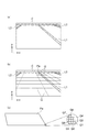
画像取得部10は、ステレオカメラ3の撮像した撮像画像を取得する。ここで、図2(a)は、ステレオカメラ3により撮像された撮像画像を示す図である。図2(a)は、車両の前方を撮像した撮像画像を示している。図2(a)には、車両の走行車線を形成する白線(車線境界線,車両通行帯境界線等)L1,L2、白線L1と共に隣接車線を形成する白線L3、及び横断歩道Cが示されている。また、図2(a)に撮像画像のxy座標系を示す。x座標は、撮像画像の横方向の座標(横座標)であり、y座標は撮像画像の縦方向の座標(縦座標)である。x座標及びy座標は、例えば、撮像画像を構成する画素単位で設定されている。xy座標系は、例えば、撮像画像の左下の角の画素Aを原点(x,y:0,0)として設定されている。
The
また、画像取得部10は、例えば、ステレオカメラ3における第1カメラ4の撮像画像及び第2カメラ5の撮像画像に基づいて、周知のステレオ画像処理等により視差情報を取得する。画像取得部10は、例えば、ステレオカメラ3における第1カメラ4の撮像画像及び第2カメラ5の撮像画像に基づいて、周知の手法により、輝度情報を取得する。輝度情報とは、例えば、撮像画像の画素毎の輝度の情報である。
The
なお、画像取得部10は、ステレオカメラ3の撮像画像に基づいて、車両の走行する走行車線の車線境界を検出してもよい。画像取得部10は、例えば、撮像画像に対して、周知の画像処理(例えばエッジ検出処理)を行うことにより白線認識(白線L1,L2の認識)を行ってもよい。この場合、画像取得部10は、車線境界検出部として機能する。
Note that the
画像領域設定部11は、ステレオカメラ3の撮像画像を分割して複数の画像領域を設定する。画像領域とは、撮像画像を分割して形成された領域である。ここで、図2(b)は、複数の画像領域が設定された撮像画像を示す図である。図2(b)に、撮像画像を分割するグリッドG、及びグリッドGによって形成された画像領域Paを示す。図2(b)に示すグリッドGの横線は、例えば、撮像画像の横方向(車両の車幅方向)と平行な複数の線である。グリッドGの縦線は、例えば、撮像画像における消失点に向かって収束する複数の線である。図2(b)に示すように、画像領域設定部11は、例えば、撮像画像の下側(すなわち車両の手前側)から上側に向かうほど画像領域の横幅が小さくなる台形状に、撮像画像を複数の画像領域に分割する。画像領域設定部11は、例えば、撮像画像の座標に基づいて、予め設定されたグリッドGを撮像画像に適用することにより画像領域を設定する。
The image
なお、図2(b)に示すグリッドG及び画像領域は一例であり、グリッドG及び画像領域の分割の方法は特に限定されず、周知の手法を採用することができる。画像領域設定部11は、例えば、撮像画像の横方向に平行な横線と撮像画像の縦方向に平行な縦線を有するグリッドGを採用することで、長方形状又は正方形状の画像領域を設定してもよい。
Note that the grid G and the image area shown in FIG. 2B are examples, and the method for dividing the grid G and the image area is not particularly limited, and a well-known method can be employed. For example, the image
続いて、図2(c)は、画像領域Paを構成する複数の画素範囲Q1〜Q8を示す図である。画素範囲とは、撮像画像上において単一の画素からなる範囲又は連続する複数の画素からなる範囲である。例えば、図2(c)に示す画素範囲Q1〜Q8は、それぞれ単一の画素からなる範囲である。画素範囲は、全ての画像領域において同数の画素を含む同形状の範囲となる。これらの複数の画素範囲が集まって画像領域を形成している。言い換えると、画像領域は、複数の画素範囲に分けられる。画像領域設定部11は、画素範囲が複数の画素からなる場合には、画像領域の設定と共に、画像領域を構成する複数の画素範囲を設定する。画像領域設定部11は、例えば、画像領域と同様に、予め設定されたグリッドを採用することで複数の画素範囲を設定する。
Next, FIG. 2C is a diagram illustrating a plurality of pixel ranges Q1 to Q8 that constitute the image area Pa. The pixel range is a range composed of a single pixel or a range composed of a plurality of continuous pixels on the captured image. For example, pixel ranges Q1 to Q8 shown in FIG. 2C are ranges each consisting of a single pixel. The pixel range is the same shape range including the same number of pixels in all the image areas. The plurality of pixel ranges are gathered to form an image area. In other words, the image area is divided into a plurality of pixel ranges. When the pixel range is composed of a plurality of pixels, the image
画像領域設定部11は、後述する立体物検出部12の検出結果に基づいて、画像領域を設定してもよい。画像領域設定部11は、例えば、立体物検出部12が立体物を検出した場合、撮像画像上で立体物を構成する画素を含まないように画像領域を設定する。これにより、路面勾配検出装置1は、撮像画像に含まれる他車両及び電柱等の立体物に起因して生じる画像範囲毎の輝度差の影響で、路面勾配の検出の精度が低下することを避けられる。
The image
また、画像領域設定部11は、撮像画像のうち予め設定された部分に対して画像領域を設定してもよい。画像領域設定部11は、例えば、画像取得部10が車両の走行する走行車線の車線境界を検出した場合、撮像画像のうち走行車線内の部分に対して画像領域を設定してもよい。これにより、路面勾配検出装置1は、走行車線外の他車両及び電柱等に起因して生じる輝度差の影響で、路面勾配の検出の精度が低下することを避けられる。
In addition, the image
立体物検出部12は、例えば、ステレオカメラ3の撮像画像に基づいて、撮像画像に含まれる立体物を検出する。立体物とは、例えば、他車両(四輪車、二輪車)、電柱又は壁等の構造物、及び歩行者である。立体物検出部12は、例えば、画像取得部10の認識した撮像画像の視差情報及び輝度情報の少なくとも一方に基づいて、周知の画像処理(例えばエッジ検出処理、パターン認識処理)により、立体物を検出する。立体物検出部12は、例えば、撮像画像に含まれる立体物を検出した場合、撮像画像上で立体物を構成する画素を認識する。
For example, the three-dimensional
なお、立体物検出部12は、車両が立体物を検出するレーダを備えている場合には、ステレオカメラ3の撮像画像の他、レーダの検出結果を利用して立体物を検出してもよい。立体物検出部12は、例えば、周知の手法により、ステレオカメラ3の撮像画像及びレーダの検出結果から撮像画像内に含まれる立体物を検出する。また、立体物検出部12は、撮像画像上における大きさが所定の大きさ以下である場合には、立体物として検出しなくてもよい。
In addition, when the vehicle includes a radar that detects a three-dimensional object, the three-dimensional
ここで、図3は、撮像画像上で立体物を構成する画素範囲を示す図である。図3に示す状況において、立体物検出部12は、ステレオカメラ3の撮像画像から立体物である先行車Nを検出する。立体物検出部12は、立体物である先行車Nを検出した場合、撮像画像上で先行車Nを構成する画素を認識する。立体物検出部12が撮像画像上で先行車Nを構成する画素を認識した場合、画像領域設定部11は、先行車Nを構成する画素を含まないように画像領域を設定する。また、画像領域設定部11は、画素範囲が複数の画素からなる場合には、先行車Nを構成する画素を含まないように画素範囲を設定する。なお、ECU2は、必ずしも立体物検出部12を有する必要はない。
Here, FIG. 3 is a diagram illustrating a pixel range constituting the three-dimensional object on the captured image. In the situation shown in FIG. 3, the three-dimensional
座標認識部13は、撮像画像における画素範囲毎の座標を認識する。座標認識部13は、画素範囲が単一の画素からなる場合、画素毎の座標を画素範囲毎の座標として認識する。座標認識部13は、例えば、画素範囲が複数の画素から構成される場合、画素範囲の中心位置の座標を画素範囲の座標として認識する。画素範囲の中心位置のx座標の値は、例えば、画素範囲を構成する各画素のx座標の値の合計を当該画素範囲を構成する画素の数で除して得られる値である。同様に、画素範囲の中心位置のy座標の値は、例えば、画素範囲を構成する各画素のy座標の値の合計を当該画素範囲を構成する画素の数で除して得られる値である。なお、座標認識部13は、画素範囲が複数の画素から構成される場合、画素範囲の中心位置の座標以外を画素範囲の座標として認識してもよい。
The coordinate
視差算出部14は、ステレオカメラ3の撮像画像に基づいて、画素範囲毎の視差を算出する。視差算出部14は、例えば、画像取得部10が撮像画像から取得した視差情報(例えば画素単位の視差情報)に基づいて、周知の手法により画素範囲毎の視差を算出する。視差算出部14は、画素範囲が単一の画素からなる場合、画素毎の視差を画素範囲毎の視差として算出する。一方、視差算出部14は、例えば、画素範囲が複数の画素からなる場合、画素範囲を構成する複数の画素の視差の平均値を当該画素範囲の視差として算出する。視差算出部14は、画素範囲を構成する複数の画素の視差のうち最小の視差又は最大の視差を画素範囲の視差として算出してもよい。
The
輝度算出部15は、ステレオカメラ3の撮像画像の輝度情報に基づいて、画素範囲毎の視差を算出する。輝度算出部15は、画素範囲が単一の画素からなる場合、画素毎の輝度を画素範囲毎の輝度として算出する。一方、輝度算出部15は、例えば、画素範囲が複数の画素からなる場合、画素範囲を構成する複数の画素の輝度の平均値を当該画素範囲の輝度として算出する。輝度算出部15は、画素範囲を構成する複数の画素の輝度のうち最小の輝度又は最大の輝度を画素範囲の輝度として算出してもよい。
The
重み付け設定部16は、座標認識部13の認識した画素範囲毎の座標及び輝度算出部15の算出した画素範囲毎の輝度に基づいて、画素範囲毎の重み付けを設定する。重み付け設定部16は、例えば、隣り合う画素範囲との輝度差が大きいほど画素範囲の重み付けを大きく設定する。
The
輝度差とは、隣り合う画素範囲の輝度の差である。重み付け設定部16は、例えば、所定の画素範囲に対して隣り合う画素範囲が複数存在する場合には、複数の隣り合う画素範囲と所定の画素範囲との輝度差のうち、最も大きい輝度差を所定の画素範囲の輝度差として用いる。重み付け設定部16は、座標認識部13の認識した画素範囲毎の座標に基づいて、隣り合う画素範囲を認識する。重み付け設定部16は、画素範囲に対して隣り合う画素範囲が複数存在する場合、最も大きい輝度差ではなく、周知の手法により求められた輝度差を画素範囲の輝度差としてもよい。また、重み付け設定部16は、輝度差の比較対象を同じ画像領域内の画素範囲に限定してもよい。重み付け設定部16は、立体物検出部12が撮像画像上で立体物を構成する画素を認識した場合、立体物を構成する画素を含む画素範囲以外を輝度差の比較対象としてもよい。
The luminance difference is a luminance difference between adjacent pixel ranges. For example, when there are a plurality of adjacent pixel ranges with respect to a predetermined pixel range, the
重み付けは、例えば、画素範囲の視差の信頼性に相当する。重み付け設定部16は、撮像画像の画像処理による視差の算出において、路面を構成する白線等に起因して輝度差が高い画素範囲は視差の算出の精度が高くなることから、隣り合う画素範囲との輝度差が大きいほど画素範囲の重み付けを大きく設定する。重み付け設定部16は、例えば、隣り合う画素範囲との輝度差に比例する大きさの重み付けを画素範囲に設定する。
The weighting corresponds to, for example, the reliability of the parallax in the pixel range. In the parallax calculation by the image processing of the captured image, the
或いは、重み付け設定部16は、隣り合う画素範囲との輝度差が第1の閾値以上である場合に、隣り合う画素範囲との輝度差が第1の閾値未満である場合と比べて画素範囲の重み付けを大きく設定する。第1の閾値は、輝度差に応じた画素範囲の重み付けのために適切に設定された閾値である。なお、重み付け設定部16は、例えば、第1の閾値より大きい第2の閾値を設定し、隣り合う画素範囲との輝度差が第2の閾値以上である場合に、隣り合う画素範囲との輝度差が第2の閾値未満である場合と比べて画素範囲の重み付けを大きく設定してもよい。同様に、重み付け設定部16は、輝度差に対して重み付けの大きさを段階的に設定するための閾値を3つ以上設定してもよい。
Alternatively, the
代表高さ算出部17は、例えば、視差算出部14の算出した画素範囲毎の視差に基づいて、画像領域毎の代表視差を算出する。代表視差とは、複数の画素範囲からなる画像領域の代表(典型)の視差として用いられる。代表視差とは、画像領域の基準となる視差である。代表高さ算出部17は、例えば、画像領域を構成する複数の画素範囲の視差の平均値を代表視差として算出する。代表高さ算出部17は、画像領域を構成する複数の画素範囲の視差の最大値と最小値の中間となる中間値を代表視差として算出してもよい。
For example, the representative
なお、代表高さ算出部17は、画素範囲毎の視差の他、重み付け設定部16の設定した画素範囲毎の重み付けの大きさに基づいて、画像領域毎の代表視差を算出してもよい。この場合の態様については後述する。
The representative
また、代表高さ算出部17は、例えば、視差算出部14の算出した画素範囲毎の視差、座標認識部13の認識した画素範囲毎の座標、及び重み付け設定部16の設定した画素範囲毎の重み付けの大きさに基づいて、画像領域毎の代表高さを算出する。
Further, the representative
代表高さ算出部17は、例えば、視差算出部14の算出した画素範囲毎の視差及び座標認識部13の認識した画素範囲毎の座標に基づいて、画素範囲毎の高さを算出する。代表高さ算出部17は、例えば、画素範囲毎の視差及び画素範囲毎の縦座標に基づいて、周知の手法(例えば所定の演算式を用いた手法)により、画素範囲毎の高さを算出する。代表高さ算出部17は、画素範囲毎の高さと重み付け設定部16の設定した画素範囲毎の重み付けの大きさに基づいて、画像領域内で高さの等しい画素範囲の重み付けを加算する。代表高さ算出部17は、例えば、画像領域内で重み付けの加算値が最も大きい高さを画像領域の代表高さとして算出する。
The representative
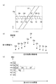
以下、重み付けを用いた代表高さの算出について説明する。ここで、図4(a)は、図2(a)と異なる路面の撮像画像に設定された画像領域を示す図である。図4(a)には、白線L4の一部を含むように設定された画像領域Pbが示されている。図4(a)に示す撮像画像のうち白線L4以外は車両が走行する走行路面である。画像領域Pbは、撮像画像上で縦座標が共通する11の画素範囲Qa〜Qkから構成されている。画素範囲Qa〜Qkは、それぞれ単一の画素からなる画素範囲とする。 Hereinafter, calculation of the representative height using weighting will be described. Here, FIG. 4A is a diagram illustrating an image region set in a captured image of a road surface different from that in FIG. FIG. 4A shows an image region Pb set so as to include a part of the white line L4. In the captured image shown in FIG. 4A, the portion other than the white line L4 is a traveling road surface on which the vehicle travels. The image area Pb is composed of eleven pixel ranges Qa to Qk having the same ordinate on the captured image. The pixel ranges Qa to Qk are pixel ranges each composed of a single pixel.
図4(b)は、輝度差と画素範囲の横座標との関係を示すグラフである。図4(b)に画素範囲Qa〜Qkにおける輝度差と第1の閾値Thを示す。ここでは、理解を容易にするため、画像領域Pb内で隣り合う画素範囲との輝度差にのみ着目する。図4(a)及び図4(b)に示すように、例えば、車両の走行する走行路面のみを含む画像範囲Qaの輝度は、同じく走行路面のみを含む画像範囲Qbの輝度と比べて差(輝度差)が小さい。一方で、白線L4の一部を含む画像範囲Qeの輝度は、走行路面のみを含む画像範囲Qdの輝度と比べて差(輝度差)が大きい。図4(b)では、白線L4のみを含む画像範囲Qfの輝度差が最も大きくなっている。 FIG. 4B is a graph showing the relationship between the luminance difference and the abscissa of the pixel range. FIG. 4B shows the luminance difference and the first threshold Th in the pixel range Qa to Qk. Here, in order to facilitate understanding, attention is focused only on the luminance difference between adjacent pixel ranges in the image region Pb. As shown in FIGS. 4A and 4B, for example, the luminance of the image range Qa including only the traveling road surface on which the vehicle travels is different from the luminance of the image range Qb including only the traveling road surface ( (Luminance difference) is small. On the other hand, the brightness (image difference) of the image range Qe including a part of the white line L4 is larger than the brightness of the image range Qd including only the traveling road surface. In FIG. 4B, the luminance difference in the image range Qf including only the white line L4 is the largest.
重み付け設定部16は、図4(b)に示す輝度差に応じて画素範囲毎の重み付けを設定する。ここでは、重み付け設定部16は、画素範囲の輝度差が第1の閾値Th以上である場合に、画素範囲の輝度差が第1の閾値Th未満である場合と比べて、画素範囲の重み付けを大きく設定する。具体的に、重み付け設定部16は、輝度差が第1の閾値Th以上である画素範囲Qe、Qf、Qgに対して、輝度差が第1の閾値Th未満である画素範囲Qa〜Qd、Qh〜Qkに比べて、重み付けを大きく設定する。
The
代表高さ算出部17は、例えば、視差算出部14の算出した画素範囲Qa〜Qkの視差及び座標認識部13の認識した画素範囲Qa〜Qkの座標に基づいて、画素範囲Qa〜Qkの高さを算出する。代表高さ算出部17は、画素範囲Qa〜Qkの高さと画素範囲Qa〜Qkの重み付けの大きさに基づいて、画像領域Pbの代表高さを算出する。
For example, the representative
図4(c)は、高さと重み付けの加算値の関係を示すグラフである。図4(c)に、高さH1〜H6を示す。高さはH1〜H6の順に大きくなる。代表高さ算出部17は、高さの等しい画素範囲が存在する場合、高さの等しい画素範囲の重み付けの大きさを高さ毎に加算する。ここで、高さが等しいとは、複数の画素範囲の高さが完全に一致する場合に限られない。代表高さ算出部17は、予め所定間隔(例えば1cm)で設定された基準高さに対して所定範囲(例えば±0.5cm)内に複数の画素範囲の高さが含まれる場合、これらの画素範囲の高さが基準高さと等しいとして扱ってもよい。図4(c)に示すH1〜H6は、基準高さに相当する。
FIG. 4C is a graph showing the relationship between the height and the added value of weighting. FIG. 4C shows the heights H1 to H6. The height increases in the order of H1 to H6. When there is a pixel range having the same height, the representative
図4(c)において、画素範囲Qaの高さは高さH6と等しい。また、画素範囲Qc,Qkの高さは高さH5と等しい。画素範囲Qb,Qd,Qe,Qfの高さは高さH5と等しい。画素範囲Qj,Qgの高さは高さH3と等しい。画素範囲Qiの高さは高さH2と等しい。画素範囲Qkの高さは高さH1と等しい。図4(c)に示すように、重み付けの加算値は、高さの等しい画素範囲が多いほど大きくなる。また、重み付けの加算値は、大きい重み付けが設定された画素範囲が含まれるほど大きくなる。上述したように、輝度差が第1の閾値Th以上である画素範囲Qe,Qf,Qgは、輝度差が第1の閾値Th未満である画素範囲Qa〜Qd、Qh〜Qkに比べて、重み付けが大きく設定されている。 In FIG. 4C, the height of the pixel range Qa is equal to the height H6. Further, the height of the pixel ranges Qc and Qk is equal to the height H5. The height of the pixel range Qb, Qd, Qe, Qf is equal to the height H5. The heights of the pixel ranges Qj and Qg are equal to the height H3. The height of the pixel range Qi is equal to the height H2. The height of the pixel range Qk is equal to the height H1. As shown in FIG. 4C, the weighted addition value increases as the number of pixel ranges having the same height increases. Further, the weighted addition value increases as the pixel range in which the greater weight is set is included. As described above, the pixel ranges Qe, Qf, and Qg whose luminance difference is greater than or equal to the first threshold Th are weighted compared to the pixel ranges Qa to Qd and Qh to Qk whose luminance difference is less than the first threshold Th. Is set larger.
図4(c)においては、高さH4が最も重み付けの加算値の大きい高さとなる。高さH4には、重み付けの大きい画素範囲Qe、Qfの高さが含まれている。また、高さH4には、最も多い4つの画素範囲Qb,Qd,Qe、Qfの高さが含まれている。代表高さ算出部17は、例えば、画像領域Pb内で重み付けの加算値が最も大きい高さH4を画像領域Pbの代表高さとして算出する。同様にして、代表高さ算出部17は、撮像画像内の画像領域毎の代表高さをそれぞれ算出する。
In FIG. 4C, the height H4 is the height with the largest weighted addition value. The height H4 includes the heights of the pixel ranges Qe and Qf having large weights. The height H4 includes the heights of the four largest pixel ranges Qb, Qd, Qe, and Qf. For example, the representative
なお、代表高さ算出部17は、重み付けの加算値が最も大きい高さH4と二番目に大きい高さH3の中間の高さを代表高さとして算出してもよい。また、代表高さ算出部17は、重み付けの加算値が最も大きい高さH4、二番目に大きい高さH3、及び三番目に大きい高さH5の平均値を代表高さとして算出してもよい。その他の態様を採用してもよい。
Note that the
路面勾配検出部18は、代表高さ算出部17の算出した画像領域毎の代表視差及び画像領域毎の代表高さに基づいて、路面勾配を算出する。路面勾配検出部18は、例えば、画像領域毎の代表視差及び代表高さを関連付けることで、車両のステレオカメラ3からの距離に応じた高さの変化である路面勾配を算出する。路面勾配検出部18は、周知の手法により、画像領域毎の代表視差及び代表高さから路面勾配を算出してもよい。
The road surface
なお、路面勾配検出部18は、画像領域毎の代表視差及び代表高さの他に、画像領域毎の代表横座標に基づいて、路面勾配を算出してもよい。この場合、座標認識部13は、例えば、画素範囲毎の座標に基づいて、画像領域毎の代表横座標を認識する。座標認識部13は、例えば、画像領域を構成する複数の画素範囲の横座標の平均値を画像領域の代表横座標として認識する。画像領域毎の代表視差、代表高さ、代表横座標を合わせて画像領域毎の代表三次元位置と称する。すなわち、路面勾配検出部18は、画像領域毎の代表三次元位置に基づいて、路面勾配を検出してもよい。路面勾配検出部18は、例えば、周知の手法により、画像領域毎の代表三次元位置から路面勾配を検出する。
The road surface
〈路面勾配検出装置における路面勾配検出制御〉
以下、本実施形態に係る路面勾配検出装置1の路面勾配検出制御について説明する。図5は、本実施形態に係る路面勾配検出装置1の路面勾配検出制御を示すフローチャートである。路面勾配検出装置1は、例えば、車両が走行中の間、予め設定された時間毎に図5に示すフローチャートの処理を繰り返す。
<Road slope detection control in road slope detector>
Hereinafter, the road surface gradient detection control of the road surface gradient detection device 1 according to the present embodiment will be described. FIG. 5 is a flowchart showing the road surface gradient detection control of the road surface gradient detection device 1 according to the present embodiment. For example, the road surface gradient detection device 1 repeats the process of the flowchart shown in FIG. 5 for each preset time while the vehicle is traveling.
図5に示すように、路面勾配検出装置1のECU2は、ステップS101として、画像取得部10によるステレオカメラ3の撮像画像の取得を行う。画像取得部10は、例えば、ステレオカメラ3における第1カメラ4の撮像画像及び第2カメラ5の撮像画像に基づいて、周知のステレオ画像処理等により視差情報を取得する。
As shown in FIG. 5, the
ステップS102において、ECU2は、画像領域設定部11により撮像画像に対する複数の画像領域の設定を行う。画像領域設定部11は、例えば、予め設定されたグリッドGを撮像画像に適用することにより、グリッドGによって区画された複数の画像領域を設定する。また、画像領域設定部11は、画素範囲が複数の画素からなる場合には、画像領域を構成する複数の画素範囲を設定する。
In step S <b> 102, the
このとき、画像領域設定部11は、立体物検出部12の検出結果に基づいて、画像領域を設定してもよい。画像領域設定部11は、立体物検出部12が立体物(例えば先行車N)を検出した場合、撮像画像上で立体物を構成する画素を含まないように画像領域を設定する。
At this time, the image
ステップS103において、ECU2は、座標認識部13により画素範囲毎の座標を認識する。座標認識部13は、撮像画像における画素毎の座標に基づいて、画素範囲毎の座標を認識する。
In step S <b> 103, the
ステップS104において、ECU2は、視差算出部14により画素範囲毎の視差を算出すると共に、輝度算出部15により画素範囲毎の輝度を算出する。視差算出部14は、画像取得部10が撮像画像から取得した視差情報に基づいて、画素範囲毎の視差を算出する。輝度算出部15は、画像取得部10が撮像画像から取得した輝度情報に基づいて、画素範囲毎の輝度として算出する。
In step S104, the
ステップS105において、ECU2は、重み付け設定部16により画素範囲毎の重み付けを設定する。重み付け設定部16は、画素範囲毎の座標及び画素範囲毎の輝度に基づいて、画素範囲毎に隣り合う画素範囲との輝度差を算出する。重み付け設定部16は、画素範囲毎の輝度差に基づいて、画素範囲毎の重み付けを設定する。重み付け設定部16は、例えば、隣り合う画素範囲との輝度差が大きいほど画素範囲の重み付けを大きく設定する。或いは、重み付け設定部16は、隣り合う画素範囲との輝度差が第1の閾値以上である場合に、隣り合う画素範囲との輝度差が第1の閾値未満である場合と比べて画素範囲の重み付けを大きく設定する。
In step S <b> 105, the
ステップS106において、ECU2は、代表高さ算出部17により画像領域毎の代表視差及び画像領域毎の代表高さを算出する。代表高さ算出部17は、画素範囲毎の視差、画素範囲毎の座標、及び画素範囲毎の重み付けの大きさに基づいて、画像領域毎の代表視差及び画像領域毎の代表高さを算出する。代表高さ算出部17は、例えば、画像領域を構成する複数の画素範囲の視差の平均値を画像領域の代表視差として算出する。また、代表高さ算出部17は、例えば、画素範囲毎の視差及び画素範囲毎の縦座標に基づいて画素範囲毎の高さを算出すると共に、画像領域内で高さの等しい画素範囲の重み付けを加算する。代表高さ算出部17は、例えば、画像領域内で重み付けの加算値が最も大きい高さを画像領域の代表高さとして算出する。
In step S106, the
ステップS107において、ECU2は、路面勾配検出部18により路面勾配を検出する。路面勾配検出部18は、代表高さ算出部17の算出した画像領域毎の代表視差及び画像領域毎の代表高さに基づいて、周知の手法により、路面勾配を算出する。
In step S107, the
〈路面勾配検出装置の作用効果〉
以上説明した本実施形態に係る路面勾配検出装置1によれば、隣り合う画素範囲との輝度差に応じて設定された画素範囲の重み付けを利用して画像領域の代表高さを算出するので、輝度差を考慮せずに画像領域の代表高さを算出する従来の場合と比べて、代表高さを精度良く算出することができる。しかも、この路面勾配検出装置1によれば、白線を含む画像領域に限定して路面勾配を検出する従来の装置と比べて、白線が認識できないほどに掠れている状態であっても輝度差が生じていれば重み付けに反映することができる。また、この路面勾配検出装置1では、白線の他に、路面の凹凸又は路面のマンホール等によって輝度差が生じる場合であっても重み付けに反映することができる。従って、この路面勾配検出装置1によれば、撮像画像内に白線が含まれない場合であっても、輝度差に応じて設定された画素範囲の重み付けを利用して代表高さを精度良く算出することができるので、路面勾配の検出精度を向上させることができる。
<Effects of road surface gradient detector>
According to the road surface gradient detection device 1 according to the present embodiment described above, the representative height of the image region is calculated using the weighting of the pixel range set according to the luminance difference between the adjacent pixel ranges. Compared to the conventional case of calculating the representative height of the image area without considering the luminance difference, the representative height can be calculated with high accuracy. Moreover, according to the road surface gradient detection device 1, a luminance difference is produced even in a state where the white line is not recognized as compared with the conventional device that detects the road surface gradient only in the image area including the white line. If it occurs, it can be reflected in the weighting. Moreover, in this road surface gradient detection apparatus 1, in addition to the white line, even when a luminance difference is caused by road surface unevenness or road surface manholes, it can be reflected in the weighting. Therefore, according to this road surface gradient detection device 1, even when a white line is not included in the captured image, the representative height is accurately calculated using the weighting of the pixel range set according to the luminance difference. Therefore, the road surface gradient detection accuracy can be improved.
また、本実施形態に係る路面勾配検出装置1では、画像範囲毎の重み付けの設定と代表高さ及び代表視差の算出から、他車両等の立体物を構成する画素範囲を除いてもよい。この場合、路面勾配検出装置1は、路面勾配検出の対象となる画像領域から他車両等の立体物を構成する画素を除くことができる。従って、この路面勾配検出装置1によれば、撮像画像内の立体物によって生じる輝度差の影響により、誤った重み付けが設定され、路面勾配の検出精度が低下することを抑制することができる。 Moreover, in the road surface gradient detection apparatus 1 according to the present embodiment, the pixel range that constitutes a three-dimensional object such as another vehicle may be excluded from the setting of the weight for each image range and the calculation of the representative height and the representative parallax. In this case, the road surface gradient detection device 1 can exclude pixels constituting a three-dimensional object such as another vehicle from an image region that is a target of road surface gradient detection. Therefore, according to the road surface gradient detection device 1, it is possible to prevent erroneous weighting from being set due to the influence of the brightness difference caused by the three-dimensional object in the captured image, and a decrease in road surface gradient detection accuracy.
更に、この路面勾配検出装置1では、代表高さ算出部17において、画素範囲毎の視差及び画素範囲毎の座標に基づいて画素範囲毎の高さを算出すると共に、画像領域内で高さの等しい画素範囲の重み付けの大きさを加算し、画像領域毎に重み付けの加算値が最も大きい高さを代表高さとして算出してもよい。この場合、路面勾配検出装置1は、画像領域内で高さの等しい画素範囲の重み付けの大きさを加算し、重み付けの加算値が最も大きい高さを画像領域の代表高さとして算出するので、画像領域内の画像範囲の視差の平均値を代表高さとするような従来の場合と比べて、代表高さを精度良く算出することができる。
Further, in this road surface gradient detection device 1, the representative
以上、本発明の好適な実施形態について説明したが、本発明は上述した実施形態に限定されるものではない。本発明は、上述した実施形態を始めとして、当業者の知識に基づいて種々の変更、改良を施した様々な形態で実施することができる。 As mentioned above, although preferred embodiment of this invention was described, this invention is not limited to embodiment mentioned above. The present invention can be implemented in various forms including various modifications and improvements based on the knowledge of those skilled in the art including the above-described embodiments.
例えば、代表高さ算出部17は、上述した代表高さの算出方法と同様に、画像範囲毎の重み付けの大きさを用いて、画像領域毎の代表視差を算出してもよい。この場合、代表高さ算出部17は、視差算出部14の算出した画素範囲毎の視差及び重み付け設定部16の設定した画素範囲毎の重み付けの大きさに基づいて、画像領域毎の代表視差を算出する。
For example, the representative
画像範囲毎の重み付けの大きさを用いた画像領域毎の代表視差の算出について、図4(a)〜図4(c)を参照して具体的に説明する。まず、上述した実施形態で説明したとおり、視差算出部14は、撮像画像の視差情報に基づいて、図4(a)に示す画素範囲Qa〜Qkの視差を算出する。輝度算出部15は、撮像画像の輝度情報に基づいて、図4(a)に示す画素範囲Qa〜Qkの輝度を算出する。また、重み付け設定部16は、図4(b)に示すように、画像範囲Qa〜Qkの輝度差に応じて画像範囲Qa〜Qkの重み付けを設定する。重み付け設定部16は、例えば、輝度差が第1の閾値Th以上である画素範囲Qe、Qf、Qgに対して、輝度差が第1の閾値Th未満である画素範囲Qa〜Qd、Qh〜Qkに比べて、重み付けを大きく設定する。なお、重み付け設定部16は、輝度差が高いほど画素範囲Qa〜Qkの重み付けを大きく設定してもよい。
The calculation of the representative parallax for each image region using the weighting amount for each image range will be specifically described with reference to FIGS. 4 (a) to 4 (c). First, as described in the above-described embodiment, the
代表高さ算出部17は、視差算出部14の算出した画素範囲Qa〜Qkの視差及び重み付け設定部16の設定した画素範囲Qa〜Qkの重み付けの大きさに基づいて、画像領域Pbの代表視差を算出する。以下、図4(c)の縦座標を高さではなく視差に置き換えて説明を行う。
Based on the parallax of the pixel range Qa to Qk calculated by the
代表高さ算出部17は、視差の等しい画素範囲が存在する場合、視差の等しい画素範囲の重み付けの大きさを視差毎に加算する。視差が等しいとは、複数の画素範囲の視差が完全に一致する場合に限られない。代表高さ算出部17は、予め所定間隔(例えば0.5m)で設定された基準視差に対して所定範囲(例えば±0.25m)内に複数の画素範囲の視差が含まれる場合、これらの画素範囲の視差が基準視差と等しいとして扱ってもよい。
When there is a pixel range with the same parallax, the representative
この場合、代表高さ算出部17は、例えば、画像領域Pb内で重み付けの加算値が最も大きい高さH4を画像領域Pbの代表高さとして算出する。同様にして、代表高さ算出部17は、撮像画像に設定された画像領域毎の代表視差をそれぞれ算出する。
In this case, for example, the representative
なお、代表高さ算出部17は、重み付けの加算値が最も大きい視差と二番目に大きい視差の中間の視差を代表視差として算出してもよい。また、代表高さ算出部17は、重み付けの加算値が最も大きい視差、二番目に大きい視差、及び三番目に大きい視差の平均値を代表視差として算出してもよい。
Note that the representative
この場合、路面勾配検出装置1では、画像領域内で視差の等しい画素範囲の重み付けの大きさを加算し、重み付けの加算値が最も大きい視差を画像領域の代表視差として算出するので、画像領域内の画像範囲の視差の平均値を代表視差とするような従来の場合と比べて、代表視差を精度良く算出することができる。 In this case, the road surface gradient detection device 1 adds the weights of the pixel ranges having the same parallax within the image area, and calculates the parallax having the largest weighted addition value as the representative parallax of the image area. Compared to the conventional case in which the average value of the parallax in the image range is used as the representative parallax, the representative parallax can be calculated with higher accuracy.
なお、この場合において、代表高さ算出部17は、画像範囲毎の重み付けの大きさを用いて算出した画像領域毎の代表視差と画像領域毎の座標に基づいて、画像領域毎の代表高さを算出することができる。座標認識部13は、例えば、画素範囲毎の座標に基づいて、画像領域毎の座標を認識する。座標認識部13は、例えば、画素範囲が複数の画素からなる場合における画素範囲の座標の認識と同様に、画像領域の中心位置の座標を画像領域の座標として認識する。代表高さ算出部17は、画像領域毎の代表視差と画像領域毎の縦座標に基づいて、周知の手法により、画像領域毎の代表高さを算出する。
In this case, the representative
或いは、代表高さ算出部17は、上述した実施形態と同様にして、画像領域毎の代表高さを算出してもよい。
Alternatively, the representative
その他、路面勾配検出装置1は、立体物検出部12が撮像画像に含まれる立体物を検出した場合であっても、撮像画像上で立体物を構成する画素を含む画像領域を設定してもよい。この場合、路面勾配検出装置1は、例えば、重み付け設定部16において、撮像画像上で立体物を構成する画素を含む画素範囲以外の画素範囲を輝度差の比較対象とすることにより、立体物に起因する輝度差の影響を抑制することができる。更に加えて、路面勾配検出装置1は、代表高さ算出部17において、立体物を構成する画素を含む画素範囲以外の画素範囲を用いて、画像領域毎の代表視差及び画像領域毎の代表高さを算出してもよい。
In addition, even when the road surface gradient detection device 1 detects the solid object included in the captured image by the solid
1…路面勾配検出装置、2…ECU、3…ステレオカメラ、4…第1カメラ、5…第2カメラ、10…画像取得部、11…画像領域設定部、12…立体物検出部、13…座標認識部、14…視差算出部、15…輝度算出部、16…重み付け設定部、17…代表高さ算出部、18…路面勾配検出部、C…横断歩道、G…グリッド、L1-L4…白線、N…先行車(立体物)、Pa,Pb…画像領域、Q1-Q8,Qa-Qk…画素範囲、Th…第1の閾値。 DESCRIPTION OF SYMBOLS 1 ... Road surface gradient detection apparatus, 2 ... ECU, 3 ... Stereo camera, 4 ... 1st camera, 5 ... 2nd camera, 10 ... Image acquisition part, 11 ... Image area setting part, 12 ... Solid object detection part, 13 ... Coordinate recognition unit, 14 ... parallax calculation unit, 15 ... luminance calculation unit, 16 ... weight setting unit, 17 ... representative height calculation unit, 18 ... road surface gradient detection unit, C ... pedestrian crossing, G ... grid, L1-L4 ... White line, N ... preceding vehicle (solid object), Pa, Pb ... image area, Q1-Q8, Qa-Qk ... pixel range, Th ... first threshold.
Claims (4)
前記撮像画像を分割して複数の画像領域を設定する画像領域設定部と、
前記画像領域を構成する画素範囲毎の座標を認識する座標認識部と、
前記撮像画像の前記視差情報に基づいて、前記画素範囲毎の視差を算出する視差算出部と、
前記撮像画像の輝度情報に基づいて、前記画素範囲毎の輝度を算出する輝度算出部と、
前記画素範囲毎の輝度及び前記画素範囲毎の座標に基づいて、隣り合う前記画素範囲との輝度差が大きいほど前記画素範囲の重み付けを大きく設定する、又は、前記画素範囲毎の輝度及び前記画素範囲毎の座標に基づいて、隣り合う前記画素範囲との輝度差が第1の閾値以上である場合に、隣り合う前記画素範囲との輝度差が前記第1の閾値未満である場合と比べて前記画素範囲の重み付けを大きく設定する重み付け設定部と、
前記画素範囲毎の前記視差、前記画素範囲毎の前記座標、及び前記画素範囲毎の前記重み付けの大きさに基づいて、前記画像領域毎の代表視差及び前記画像領域毎の代表高さを算出する代表高さ算出部と、
前記画像領域毎の代表視差及び前記画像領域毎の前記代表高さに基づいて、前記撮像画像から前記路面勾配を検出する路面勾配検出部と、
を備える、路面勾配検出装置。 A road surface gradient detection device that detects a road surface gradient based on parallax information obtained from a captured image around a vehicle imaged by an in-vehicle camera,
An image region setting unit that divides the captured image and sets a plurality of image regions;
A coordinate recognition unit for recognizing coordinates for each pixel range constituting the image area;
A parallax calculation unit that calculates parallax for each pixel range based on the parallax information of the captured image;
A luminance calculation unit that calculates luminance for each pixel range based on luminance information of the captured image;
Based on the luminance for each pixel range and the coordinates for each pixel range, the weighting of the pixel range is set to be larger as the luminance difference between adjacent pixel ranges is larger, or the luminance for each pixel range and the pixel Based on the coordinates of each range, when the luminance difference between the adjacent pixel ranges is equal to or greater than the first threshold, compared to the case where the luminance difference between the adjacent pixel ranges is less than the first threshold. A weight setting unit for setting a large weight for the pixel range;
Based on the parallax for each pixel range, the coordinates for each pixel range, and the weighting size for each pixel range, a representative parallax for each image region and a representative height for each image region are calculated. A representative height calculator,
A road gradient detector that detects the road gradient from the captured image based on the representative parallax for each image region and the representative height for each image region;
A road surface gradient detecting device.
前記画像領域設定部は、前記撮像画像上で前記立体物を構成する画素を含まないように前記画像領域を設定する、請求項1に記載の路面勾配検出装置。 A solid object detection unit for detecting a solid object included in the captured image;
The road surface gradient detection device according to claim 1, wherein the image region setting unit sets the image region so as not to include pixels constituting the three-dimensional object on the captured image.
Priority Applications (4)
| Application Number | Priority Date | Filing Date | Title |
|---|---|---|---|
| JP2015084936A JP6233345B2 (en) | 2015-04-17 | 2015-04-17 | Road surface gradient detector |
| CN201610183705.0A CN106056570B (en) | 2015-04-17 | 2016-03-28 | Road gradient detection device |
| US15/092,852 US9771080B2 (en) | 2015-04-17 | 2016-04-07 | Road surface gradient detection device |
| EP16165327.4A EP3082066B1 (en) | 2015-04-17 | 2016-04-14 | Road surface gradient detection device |
Applications Claiming Priority (1)
| Application Number | Priority Date | Filing Date | Title |
|---|---|---|---|
| JP2015084936A JP6233345B2 (en) | 2015-04-17 | 2015-04-17 | Road surface gradient detector |
Publications (2)
| Publication Number | Publication Date |
|---|---|
| JP2016205887A JP2016205887A (en) | 2016-12-08 |
| JP6233345B2 true JP6233345B2 (en) | 2017-11-22 |
Family
ID=55755414
Family Applications (1)
| Application Number | Title | Priority Date | Filing Date |
|---|---|---|---|
| JP2015084936A Active JP6233345B2 (en) | 2015-04-17 | 2015-04-17 | Road surface gradient detector |
Country Status (4)
| Country | Link |
|---|---|
| US (1) | US9771080B2 (en) |
| EP (1) | EP3082066B1 (en) |
| JP (1) | JP6233345B2 (en) |
| CN (1) | CN106056570B (en) |
Families Citing this family (17)
| Publication number | Priority date | Publication date | Assignee | Title |
|---|---|---|---|---|
| JP5959073B2 (en) | 2014-09-30 | 2016-08-02 | インターナショナル・ビジネス・マシーンズ・コーポレーションInternational Business Machines Corporation | Detection device, detection method, and program |
| RU2667026C1 (en) * | 2015-08-04 | 2018-09-13 | Ниссан Мотор Ко., Лтд. | Bench detection device and a bench detection method |
| JP6451858B2 (en) * | 2015-08-04 | 2019-01-16 | 日産自動車株式会社 | Step detecting device and step detecting method |
| JP6547785B2 (en) * | 2016-07-29 | 2019-07-24 | 株式会社デンソー | Target detection device |
| CN108466618B (en) * | 2017-02-23 | 2019-11-01 | 上海汽车集团股份有限公司 | Adaptive cruise control method and system |
| KR102317185B1 (en) * | 2017-06-14 | 2021-10-26 | 현대자동차주식회사 | Vehicle, and control method for the same |
| JP6849569B2 (en) * | 2017-09-29 | 2021-03-24 | トヨタ自動車株式会社 | Road surface detector |
| JP2019078648A (en) * | 2017-10-25 | 2019-05-23 | パナソニックIpマネジメント株式会社 | Road surface detector, method for detecting road surface, road surface detection program, and recording medium recording road surface detection program |
| JP7009945B2 (en) * | 2017-11-15 | 2022-01-26 | 株式会社豊田自動織機 | Image processing equipment and vehicles |
| US11443619B2 (en) * | 2018-05-15 | 2022-09-13 | Kabushiki Kaisha Toshiba | Vehicle recognition apparatus and vehicle recognition method |
| US11182914B2 (en) | 2018-05-21 | 2021-11-23 | Facebook Technologies, Llc | Dynamic structured light for depth sensing systems based on contrast in a local area |
| CN109387855B (en) * | 2018-10-29 | 2020-09-22 | 浙江大学 | System for predicting slope gradient and slope length in advance by utilizing vehicle-mounted pulse laser radar |
| CN109974662B (en) * | 2019-04-24 | 2020-12-15 | 重庆理工大学 | Bicycle for road information acquisition and road information acquisition method |
| CN111829484B (en) * | 2020-06-03 | 2022-05-03 | 江西江铃集团新能源汽车有限公司 | Target distance measuring and calculating method based on vision |
| CN112254683B (en) * | 2020-10-27 | 2021-09-03 | 常州市新创智能科技有限公司 | Composite pultrusion part straightness evaluation method |
| US11741718B2 (en) * | 2021-05-18 | 2023-08-29 | Hitachi Astemo, Ltd. | Light interference detection during vehicle navigation |
| CN116625317B (en) * | 2023-07-26 | 2023-10-03 | 天津达一众诚科技有限公司 | Steep slope surface gradient detection method and device based on image processing |
Family Cites Families (22)
| Publication number | Priority date | Publication date | Assignee | Title |
|---|---|---|---|---|
| US5487116A (en) * | 1993-05-25 | 1996-01-23 | Matsushita Electric Industrial Co., Ltd. | Vehicle recognition apparatus |
| JPH09325026A (en) | 1996-06-03 | 1997-12-16 | Nissan Motor Co Ltd | Method for detecting gradient and gradient angle of forward road |
| JP3373773B2 (en) * | 1998-01-27 | 2003-02-04 | 株式会社デンソー | Lane mark recognition device, vehicle travel control device, and recording medium |
| JP3352655B2 (en) * | 1999-09-22 | 2002-12-03 | 富士重工業株式会社 | Lane recognition device |
| EP2393301A1 (en) * | 2007-06-11 | 2011-12-07 | Samsung Electronics Co., Ltd. | Method and apparatus for generating header information of stereoscopic image |
| FR2922671B1 (en) * | 2007-10-17 | 2010-03-12 | Valeo Vision | METHOD FOR THE AUTOMATIC DETERMINATION OF COEFFICIENT OF A SLOPE ON THE POINT BEING ABORDIED BY A MOTOR VEHICLE AND ASSOCIATED DEVICE |
| JP2009139325A (en) * | 2007-12-10 | 2009-06-25 | Mazda Motor Corp | Travel road surface detecting apparatus for vehicle |
| JP4876080B2 (en) * | 2008-01-25 | 2012-02-15 | 富士重工業株式会社 | Environment recognition device |
| DE102009033219A1 (en) * | 2009-01-23 | 2010-07-29 | Daimler Ag | Method for determining a road profile of a traffic lane ahead of a vehicle |
| JP5188452B2 (en) * | 2009-05-22 | 2013-04-24 | 富士重工業株式会社 | Road shape recognition device |
| JP5440461B2 (en) * | 2010-09-13 | 2014-03-12 | 株式会社リコー | Calibration apparatus, distance measurement system, calibration method, and calibration program |
| JP5693994B2 (en) * | 2011-02-16 | 2015-04-01 | 富士重工業株式会社 | Vehicle detection device |
| JP5503578B2 (en) * | 2011-03-10 | 2014-05-28 | パナソニック株式会社 | Object detection apparatus and object detection method |
| JP6182866B2 (en) * | 2012-03-21 | 2017-08-23 | 株式会社リコー | Calibration device, distance measuring device, and vehicle |
| US9031316B2 (en) * | 2012-04-05 | 2015-05-12 | Mediatek Singapore Pte. Ltd. | Method for identifying view order of image frames of stereo image pair according to image characteristics and related machine readable medium thereof |
| JP2014006882A (en) * | 2012-05-31 | 2014-01-16 | Ricoh Co Ltd | Road surface slope recognition device, road surface slope recognition method, and road surface slope recognition program |
| EP2669845A3 (en) * | 2012-06-01 | 2014-11-19 | Ricoh Company, Ltd. | Target recognition system, target recognition method executed by the target recognition system, target recognition program executed on the target recognition system, and recording medium storing the target recognition program |
| JP6376429B2 (en) * | 2012-11-13 | 2018-08-22 | 株式会社リコー | Target point arrival detection device, target point arrival detection program, mobile device control system, and mobile |
| CN104166834B (en) * | 2013-05-20 | 2017-10-10 | 株式会社理光 | Pavement detection method and apparatus |
| CN104252707B (en) * | 2013-06-27 | 2017-06-06 | 株式会社理光 | Method for checking object and device |
| JP5893601B2 (en) * | 2013-10-31 | 2016-03-23 | 富士重工業株式会社 | Vehicle control system |
| JP5906272B2 (en) * | 2014-03-28 | 2016-04-20 | 富士重工業株式会社 | Stereo image processing apparatus for vehicle |
-
2015
- 2015-04-17 JP JP2015084936A patent/JP6233345B2/en active Active
-
2016
- 2016-03-28 CN CN201610183705.0A patent/CN106056570B/en active Active
- 2016-04-07 US US15/092,852 patent/US9771080B2/en active Active
- 2016-04-14 EP EP16165327.4A patent/EP3082066B1/en active Active
Also Published As
| Publication number | Publication date |
|---|---|
| CN106056570A (en) | 2016-10-26 |
| EP3082066A1 (en) | 2016-10-19 |
| CN106056570B (en) | 2019-02-19 |
| US20160304098A1 (en) | 2016-10-20 |
| JP2016205887A (en) | 2016-12-08 |
| US9771080B2 (en) | 2017-09-26 |
| EP3082066B1 (en) | 2019-01-09 |
Similar Documents
| Publication | Publication Date | Title |
|---|---|---|
| JP6233345B2 (en) | Road surface gradient detector | |
| JP4956452B2 (en) | Vehicle environment recognition device | |
| JP5804185B2 (en) | Moving object position / orientation estimation apparatus and moving object position / orientation estimation method | |
| US9912933B2 (en) | Road surface detection device and road surface detection system | |
| US20140071240A1 (en) | Free space detection system and method for a vehicle using stereo vision | |
| JP6156400B2 (en) | Traveling road surface detection device and traveling road surface detection method | |
| JP5631581B2 (en) | Road recognition device | |
| JP6171593B2 (en) | Object tracking method and system from parallax map | |
| JP6358160B2 (en) | Traveling road surface detection device and traveling road surface detection method | |
| JP2009176090A (en) | Environment recognition system | |
| JP5180126B2 (en) | Road recognition device | |
| JP5874831B2 (en) | Three-dimensional object detection device | |
| JP2016133838A (en) | Composite line determination device and composite line determination method | |
| JP6396729B2 (en) | Three-dimensional object detection device | |
| JP5073700B2 (en) | Object detection device | |
| JP2012252501A (en) | Traveling path recognition device and traveling path recognition program | |
| JP5091897B2 (en) | Stop line detector | |
| JP2013186718A (en) | Mobile object position attitude estimation device and method | |
| JP6466679B2 (en) | Object detection device | |
| JP2017207881A (en) | Image processing apparatus, imaging apparatus, moving body device control system, image processing method, and program | |
| JP2019091295A (en) | Image processing device | |
| JP3104645B2 (en) | Road white line detection method and road white line detection device | |
| JP5472137B2 (en) | Boundary detection device and boundary detection program | |
| JP6561688B2 (en) | DETECTING DEVICE, DETECTING METHOD, IMAGING DEVICE, DEVICE CONTROL SYSTEM, AND PROGRAM | |
| JP2015156120A (en) | pedestrian recognition device |
Legal Events
| Date | Code | Title | Description |
|---|---|---|---|
| A621 | Written request for application examination |
Free format text: JAPANESE INTERMEDIATE CODE: A621 Effective date: 20161209 |
|
| A977 | Report on retrieval |
Free format text: JAPANESE INTERMEDIATE CODE: A971007 Effective date: 20170913 |
|
| TRDD | Decision of grant or rejection written | ||
| A01 | Written decision to grant a patent or to grant a registration (utility model) |
Free format text: JAPANESE INTERMEDIATE CODE: A01 Effective date: 20170926 |
|
| A61 | First payment of annual fees (during grant procedure) |
Free format text: JAPANESE INTERMEDIATE CODE: A61 Effective date: 20171009 |
|
| R151 | Written notification of patent or utility model registration |
Ref document number: 6233345 Country of ref document: JP Free format text: JAPANESE INTERMEDIATE CODE: R151 |