JP6232085B2 - Vehicle control device - Google Patents
Vehicle control device Download PDFInfo
- Publication number
- JP6232085B2 JP6232085B2 JP2016013911A JP2016013911A JP6232085B2 JP 6232085 B2 JP6232085 B2 JP 6232085B2 JP 2016013911 A JP2016013911 A JP 2016013911A JP 2016013911 A JP2016013911 A JP 2016013911A JP 6232085 B2 JP6232085 B2 JP 6232085B2
- Authority
- JP
- Japan
- Prior art keywords
- opening
- engine
- valve
- error
- vehicle
- Prior art date
- Legal status (The legal status is an assumption and is not a legal conclusion. Google has not performed a legal analysis and makes no representation as to the accuracy of the status listed.)
- Active
Links
Images

Classifications
-
- F—MECHANICAL ENGINEERING; LIGHTING; HEATING; WEAPONS; BLASTING
- F02—COMBUSTION ENGINES; HOT-GAS OR COMBUSTION-PRODUCT ENGINE PLANTS
- F02B—INTERNAL-COMBUSTION PISTON ENGINES; COMBUSTION ENGINES IN GENERAL
- F02B37/00—Engines characterised by provision of pumps driven at least for part of the time by exhaust
- F02B37/12—Control of the pumps
- F02B37/18—Control of the pumps by bypassing exhaust from the inlet to the outlet of turbine or to the atmosphere
- F02B37/183—Arrangements of bypass valves or actuators therefor
-
- B—PERFORMING OPERATIONS; TRANSPORTING
- B60—VEHICLES IN GENERAL
- B60W—CONJOINT CONTROL OF VEHICLE SUB-UNITS OF DIFFERENT TYPE OR DIFFERENT FUNCTION; CONTROL SYSTEMS SPECIALLY ADAPTED FOR HYBRID VEHICLES; ROAD VEHICLE DRIVE CONTROL SYSTEMS FOR PURPOSES NOT RELATED TO THE CONTROL OF A PARTICULAR SUB-UNIT
- B60W20/00—Control systems specially adapted for hybrid vehicles
-
- B—PERFORMING OPERATIONS; TRANSPORTING
- B60—VEHICLES IN GENERAL
- B60K—ARRANGEMENT OR MOUNTING OF PROPULSION UNITS OR OF TRANSMISSIONS IN VEHICLES; ARRANGEMENT OR MOUNTING OF PLURAL DIVERSE PRIME-MOVERS IN VEHICLES; AUXILIARY DRIVES FOR VEHICLES; INSTRUMENTATION OR DASHBOARDS FOR VEHICLES; ARRANGEMENTS IN CONNECTION WITH COOLING, AIR INTAKE, GAS EXHAUST OR FUEL SUPPLY OF PROPULSION UNITS IN VEHICLES
- B60K6/00—Arrangement or mounting of plural diverse prime-movers for mutual or common propulsion, e.g. hybrid propulsion systems comprising electric motors and internal combustion engines ; Control systems therefor, i.e. systems controlling two or more prime movers, or controlling one of these prime movers and any of the transmission, drive or drive units Informative references: mechanical gearings with secondary electric drive F16H3/72; arrangements for handling mechanical energy structurally associated with the dynamo-electric machine H02K7/00; machines comprising structurally interrelated motor and generator parts H02K51/00; dynamo-electric machines not otherwise provided for in H02K see H02K99/00
- B60K6/20—Arrangement or mounting of plural diverse prime-movers for mutual or common propulsion, e.g. hybrid propulsion systems comprising electric motors and internal combustion engines ; Control systems therefor, i.e. systems controlling two or more prime movers, or controlling one of these prime movers and any of the transmission, drive or drive units Informative references: mechanical gearings with secondary electric drive F16H3/72; arrangements for handling mechanical energy structurally associated with the dynamo-electric machine H02K7/00; machines comprising structurally interrelated motor and generator parts H02K51/00; dynamo-electric machines not otherwise provided for in H02K see H02K99/00 the prime-movers consisting of electric motors and internal combustion engines, e.g. HEVs
- B60K6/42—Arrangement or mounting of plural diverse prime-movers for mutual or common propulsion, e.g. hybrid propulsion systems comprising electric motors and internal combustion engines ; Control systems therefor, i.e. systems controlling two or more prime movers, or controlling one of these prime movers and any of the transmission, drive or drive units Informative references: mechanical gearings with secondary electric drive F16H3/72; arrangements for handling mechanical energy structurally associated with the dynamo-electric machine H02K7/00; machines comprising structurally interrelated motor and generator parts H02K51/00; dynamo-electric machines not otherwise provided for in H02K see H02K99/00 the prime-movers consisting of electric motors and internal combustion engines, e.g. HEVs characterised by the architecture of the hybrid electric vehicle
- B60K6/44—Series-parallel type
- B60K6/445—Differential gearing distribution type
-
- B—PERFORMING OPERATIONS; TRANSPORTING
- B60—VEHICLES IN GENERAL
- B60W—CONJOINT CONTROL OF VEHICLE SUB-UNITS OF DIFFERENT TYPE OR DIFFERENT FUNCTION; CONTROL SYSTEMS SPECIALLY ADAPTED FOR HYBRID VEHICLES; ROAD VEHICLE DRIVE CONTROL SYSTEMS FOR PURPOSES NOT RELATED TO THE CONTROL OF A PARTICULAR SUB-UNIT
- B60W20/00—Control systems specially adapted for hybrid vehicles
- B60W20/10—Controlling the power contribution of each of the prime movers to meet required power demand
- B60W20/15—Control strategies specially adapted for achieving a particular effect
- B60W20/17—Control strategies specially adapted for achieving a particular effect for noise reduction
-
- B—PERFORMING OPERATIONS; TRANSPORTING
- B60—VEHICLES IN GENERAL
- B60W—CONJOINT CONTROL OF VEHICLE SUB-UNITS OF DIFFERENT TYPE OR DIFFERENT FUNCTION; CONTROL SYSTEMS SPECIALLY ADAPTED FOR HYBRID VEHICLES; ROAD VEHICLE DRIVE CONTROL SYSTEMS FOR PURPOSES NOT RELATED TO THE CONTROL OF A PARTICULAR SUB-UNIT
- B60W20/00—Control systems specially adapted for hybrid vehicles
- B60W20/40—Controlling the engagement or disengagement of prime movers, e.g. for transition between prime movers
-
- F—MECHANICAL ENGINEERING; LIGHTING; HEATING; WEAPONS; BLASTING
- F02—COMBUSTION ENGINES; HOT-GAS OR COMBUSTION-PRODUCT ENGINE PLANTS
- F02B—INTERNAL-COMBUSTION PISTON ENGINES; COMBUSTION ENGINES IN GENERAL
- F02B33/00—Engines characterised by provision of pumps for charging or scavenging
- F02B33/32—Engines with pumps other than of reciprocating-piston type
- F02B33/34—Engines with pumps other than of reciprocating-piston type with rotary pumps
-
- F—MECHANICAL ENGINEERING; LIGHTING; HEATING; WEAPONS; BLASTING
- F02—COMBUSTION ENGINES; HOT-GAS OR COMBUSTION-PRODUCT ENGINE PLANTS
- F02B—INTERNAL-COMBUSTION PISTON ENGINES; COMBUSTION ENGINES IN GENERAL
- F02B37/00—Engines characterised by provision of pumps driven at least for part of the time by exhaust
- F02B37/12—Control of the pumps
- F02B37/18—Control of the pumps by bypassing exhaust from the inlet to the outlet of turbine or to the atmosphere
-
- F—MECHANICAL ENGINEERING; LIGHTING; HEATING; WEAPONS; BLASTING
- F02—COMBUSTION ENGINES; HOT-GAS OR COMBUSTION-PRODUCT ENGINE PLANTS
- F02D—CONTROLLING COMBUSTION ENGINES
- F02D17/00—Controlling engines by cutting out individual cylinders; Rendering engines inoperative or idling
- F02D17/04—Controlling engines by cutting out individual cylinders; Rendering engines inoperative or idling rendering engines inoperative or idling, e.g. caused by abnormal conditions
-
- F—MECHANICAL ENGINEERING; LIGHTING; HEATING; WEAPONS; BLASTING
- F02—COMBUSTION ENGINES; HOT-GAS OR COMBUSTION-PRODUCT ENGINE PLANTS
- F02D—CONTROLLING COMBUSTION ENGINES
- F02D41/00—Electrical control of supply of combustible mixture or its constituents
- F02D41/0002—Controlling intake air
- F02D41/0007—Controlling intake air for control of turbo-charged or super-charged engines
-
- F—MECHANICAL ENGINEERING; LIGHTING; HEATING; WEAPONS; BLASTING
- F02—COMBUSTION ENGINES; HOT-GAS OR COMBUSTION-PRODUCT ENGINE PLANTS
- F02D—CONTROLLING COMBUSTION ENGINES
- F02D41/00—Electrical control of supply of combustible mixture or its constituents
- F02D41/02—Circuit arrangements for generating control signals
- F02D41/04—Introducing corrections for particular operating conditions
- F02D41/042—Introducing corrections for particular operating conditions for stopping the engine
-
- F—MECHANICAL ENGINEERING; LIGHTING; HEATING; WEAPONS; BLASTING
- F02—COMBUSTION ENGINES; HOT-GAS OR COMBUSTION-PRODUCT ENGINE PLANTS
- F02D—CONTROLLING COMBUSTION ENGINES
- F02D41/00—Electrical control of supply of combustible mixture or its constituents
- F02D41/02—Circuit arrangements for generating control signals
- F02D41/04—Introducing corrections for particular operating conditions
- F02D41/06—Introducing corrections for particular operating conditions for engine starting or warming up
- F02D41/062—Introducing corrections for particular operating conditions for engine starting or warming up for starting
- F02D41/065—Introducing corrections for particular operating conditions for engine starting or warming up for starting at hot start or restart
-
- B—PERFORMING OPERATIONS; TRANSPORTING
- B60—VEHICLES IN GENERAL
- B60W—CONJOINT CONTROL OF VEHICLE SUB-UNITS OF DIFFERENT TYPE OR DIFFERENT FUNCTION; CONTROL SYSTEMS SPECIALLY ADAPTED FOR HYBRID VEHICLES; ROAD VEHICLE DRIVE CONTROL SYSTEMS FOR PURPOSES NOT RELATED TO THE CONTROL OF A PARTICULAR SUB-UNIT
- B60W2510/00—Input parameters relating to a particular sub-units
- B60W2510/06—Combustion engines, Gas turbines
- B60W2510/0633—Turbocharger state
-
- B—PERFORMING OPERATIONS; TRANSPORTING
- B60—VEHICLES IN GENERAL
- B60W—CONJOINT CONTROL OF VEHICLE SUB-UNITS OF DIFFERENT TYPE OR DIFFERENT FUNCTION; CONTROL SYSTEMS SPECIALLY ADAPTED FOR HYBRID VEHICLES; ROAD VEHICLE DRIVE CONTROL SYSTEMS FOR PURPOSES NOT RELATED TO THE CONTROL OF A PARTICULAR SUB-UNIT
- B60W2710/00—Output or target parameters relating to a particular sub-units
- B60W2710/06—Combustion engines, Gas turbines
- B60W2710/0638—Turbocharger state
-
- B—PERFORMING OPERATIONS; TRANSPORTING
- B60—VEHICLES IN GENERAL
- B60W—CONJOINT CONTROL OF VEHICLE SUB-UNITS OF DIFFERENT TYPE OR DIFFERENT FUNCTION; CONTROL SYSTEMS SPECIALLY ADAPTED FOR HYBRID VEHICLES; ROAD VEHICLE DRIVE CONTROL SYSTEMS FOR PURPOSES NOT RELATED TO THE CONTROL OF A PARTICULAR SUB-UNIT
- B60W2710/00—Output or target parameters relating to a particular sub-units
- B60W2710/08—Electric propulsion units
-
- B—PERFORMING OPERATIONS; TRANSPORTING
- B60—VEHICLES IN GENERAL
- B60Y—INDEXING SCHEME RELATING TO ASPECTS CROSS-CUTTING VEHICLE TECHNOLOGY
- B60Y2400/00—Special features of vehicle units
- B60Y2400/43—Engines
- B60Y2400/435—Supercharger or turbochargers
-
- F—MECHANICAL ENGINEERING; LIGHTING; HEATING; WEAPONS; BLASTING
- F02—COMBUSTION ENGINES; HOT-GAS OR COMBUSTION-PRODUCT ENGINE PLANTS
- F02N—STARTING OF COMBUSTION ENGINES; STARTING AIDS FOR SUCH ENGINES, NOT OTHERWISE PROVIDED FOR
- F02N11/00—Starting of engines by means of electric motors
- F02N11/08—Circuits or control means specially adapted for starting of engines
- F02N11/0814—Circuits or control means specially adapted for starting of engines comprising means for controlling automatic idle-start-stop
-
- Y—GENERAL TAGGING OF NEW TECHNOLOGICAL DEVELOPMENTS; GENERAL TAGGING OF CROSS-SECTIONAL TECHNOLOGIES SPANNING OVER SEVERAL SECTIONS OF THE IPC; TECHNICAL SUBJECTS COVERED BY FORMER USPC CROSS-REFERENCE ART COLLECTIONS [XRACs] AND DIGESTS
- Y02—TECHNOLOGIES OR APPLICATIONS FOR MITIGATION OR ADAPTATION AGAINST CLIMATE CHANGE
- Y02T—CLIMATE CHANGE MITIGATION TECHNOLOGIES RELATED TO TRANSPORTATION
- Y02T10/00—Road transport of goods or passengers
- Y02T10/10—Internal combustion engine [ICE] based vehicles
- Y02T10/12—Improving ICE efficiencies
-
- Y—GENERAL TAGGING OF NEW TECHNOLOGICAL DEVELOPMENTS; GENERAL TAGGING OF CROSS-SECTIONAL TECHNOLOGIES SPANNING OVER SEVERAL SECTIONS OF THE IPC; TECHNICAL SUBJECTS COVERED BY FORMER USPC CROSS-REFERENCE ART COLLECTIONS [XRACs] AND DIGESTS
- Y02—TECHNOLOGIES OR APPLICATIONS FOR MITIGATION OR ADAPTATION AGAINST CLIMATE CHANGE
- Y02T—CLIMATE CHANGE MITIGATION TECHNOLOGIES RELATED TO TRANSPORTATION
- Y02T10/00—Road transport of goods or passengers
- Y02T10/60—Other road transportation technologies with climate change mitigation effect
- Y02T10/62—Hybrid vehicles
-
- Y—GENERAL TAGGING OF NEW TECHNOLOGICAL DEVELOPMENTS; GENERAL TAGGING OF CROSS-SECTIONAL TECHNOLOGIES SPANNING OVER SEVERAL SECTIONS OF THE IPC; TECHNICAL SUBJECTS COVERED BY FORMER USPC CROSS-REFERENCE ART COLLECTIONS [XRACs] AND DIGESTS
- Y10—TECHNICAL SUBJECTS COVERED BY FORMER USPC
- Y10S—TECHNICAL SUBJECTS COVERED BY FORMER USPC CROSS-REFERENCE ART COLLECTIONS [XRACs] AND DIGESTS
- Y10S903/00—Hybrid electric vehicles, HEVS
- Y10S903/902—Prime movers comprising electrical and internal combustion motors
- Y10S903/903—Prime movers comprising electrical and internal combustion motors having energy storing means, e.g. battery, capacitor
- Y10S903/93—Conjoint control of different elements
Description
本発明は、内燃機関及び電動機を駆動源として備える車両の制御装置に関し、特に内燃機関が、タービン及びコンプレッサを有する過給機と、タービンをバイパスするバイパス通路に設けられたウエストゲート弁とを備える車両の制御装置に関する。 The present invention relates to a control apparatus for a vehicle including an internal combustion engine and an electric motor as a drive source, and in particular, the internal combustion engine includes a supercharger having a turbine and a compressor, and a wastegate valve provided in a bypass passage that bypasses the turbine. The present invention relates to a vehicle control device.
特許文献1には、過給機及びウエストゲート弁を備える内燃機関の制御装置が示されている。この制御装置によれば、所定の自動停止条件が成立したときに機関を自動停止させるアイドリングストップを実行する際に、電力消費を抑制するためにウエストゲート弁のアクチュエータへの通電が停止される。これによって、ウエストゲート弁の閉弁状態が維持されなくなるため、アイドリングストップ中に機関再始動条件が成立すると、アクチュエータへの通電を開始してウエストゲート弁を閉弁させた後に機関再始動が行われる。機関再始動を開始する前にウエストゲート弁を閉弁させることによって、再始動時における振動が抑制される。
内燃機関及び電動機を駆動源として備える車両は、電動機のみを駆動源として使用する電動機駆動モードでの走行が可能であり、電動機駆動モードでは機関を自動的に停止させ、電動機駆動モードから機関のみを駆動源とする機関駆動モードまたは機関及び電動機を共に駆動源とするハイブリッドモードでの走行に移行する(電動機駆動モードを終了する)ときに機関の再始動が行われる。 A vehicle having an internal combustion engine and an electric motor as a drive source can travel in an electric motor drive mode using only the electric motor as a drive source. In the electric motor drive mode, the engine is automatically stopped and only the engine is switched from the electric motor drive mode. The engine is restarted when the vehicle shifts to traveling in the engine drive mode using the drive source or in the hybrid mode using both the engine and the motor as drive sources (ending the motor drive mode).
この電動機駆動モードにおいて上記特許文献1に示されるようにアクチュエータへの通電を停止すると、車両の走行に伴う振動によってウエストゲート弁の弁体がバイパス通路あるいは排気通路の内壁に当たってノイズを発生する可能性がある。電動機駆動モードでは機関が停止しているため、比較的小さいノイズであっても運転者に違和感を与える。また、このような機械的なノイズを防止するために、弁体を全閉位置に押しつけるようにアクチュエータに駆動パルス信号を供給すると、消費電力が増加するだけでなく電磁波ノイズ(広帯域放射ノイズ)が発生するという問題も発生する。
In this electric motor drive mode, when energization to the actuator is stopped as shown in
本発明はこの点に着目してなされたものであり、内燃機関及び電動機を駆動源として備える車両が電動機駆動モードで走行しているときに、振動によってウエストゲート弁から機械的ノイズが発生すること、及びアクチュエータから電磁波ノイズが発生することを防止できる車両の制御装置を提供することを目的とする。 The present invention has been made paying attention to this point, and when a vehicle equipped with an internal combustion engine and an electric motor as a drive source is traveling in the electric motor drive mode, mechanical noise is generated from the wastegate valve due to vibration. An object of the present invention is to provide a vehicle control device that can prevent electromagnetic noise from being generated from an actuator.
上記目的を達成するため請求項1に記載の発明は、内燃機関(1)及び電動機(61)を駆動源として備える車両の制御装置であって、前記機関は、排気通路(10)に設けられたタービン(121)と、前記タービンにより回転駆動され、前記機関の吸気を加圧するコンプレッサ(123)とを有する過給機(12)と、前記タービンをバイパスするバイパス通路(11)に設けられたウエストゲート弁(14)とを備える車両の制御装置において、前記車両は前記電動機のみを駆動源とする電動機駆動モードでの走行が可能であり、前記電動機駆動モードでの走行中に前記機関を自動停止させる一時停止手段と、前記ウエストゲート弁の開度(WGO)を検出する開度検出手段(23)と、前記電動機駆動モードにおいて前記ウエストゲート弁の目標開度(WGCMD)を所定開度(WGX)に設定し、前記開度検出手段により検出される開度(WGO)が前記目標開度(WGCMD)と一致するように前記ウエストゲート弁(14)を制御する弁制御手段とを備え、前記所定開度(WGO)は、前記検出される開度(WGO)と、前記ウエストゲート弁の実開度(WGA)との誤差が想定される最大値(EMAX)となった状態において、前記実開度(WGA)が全閉開度(0)以下とならない非接触条件を満たすように設定されることを特徴とする。 In order to achieve the above object, a first aspect of the present invention provides a vehicle control device including an internal combustion engine (1) and an electric motor (61) as drive sources, the engine being provided in an exhaust passage (10). A turbocharger (12) having a turbine (121) and a compressor (123) that is rotationally driven by the turbine and pressurizes intake air of the engine, and a bypass passage (11) that bypasses the turbine. In the control apparatus for a vehicle including a wastegate valve (14), the vehicle can travel in an electric motor drive mode using only the electric motor as a drive source, and the engine is automatically operated during the travel in the electric motor drive mode. A temporary stop means for stopping, an opening degree detecting means (23) for detecting an opening degree (WGO) of the waste gate valve, and the waist gauge in the motor drive mode; The waste gate is set so that the target opening (WGCMD) of the second valve is set to a predetermined opening (WGX), and the opening (WGO) detected by the opening detecting means coincides with the target opening (WGCMD). Valve control means for controlling the valve (14), and the predetermined opening (WGO) is assumed to be an error between the detected opening (WGO) and the actual opening (WGA) of the wastegate valve. The actual opening (WGA) is set so as to satisfy a non-contact condition in which the actual opening (WGA) is not less than or equal to the fully closed opening (0).
この構成によれば、電動機のみを駆動源として車両が駆動される電動機駆動モードでの走行中に、機関が自動停止されるとともに、ウエストゲート弁の目標開度が所定開度に設定され、開度検出手段によって検出される開度が目標開度と一致するようにウエストゲート弁が制御される。その際、所定開度は、検出される開度と、ウエストゲート弁の実開度との誤差が想定される最大値となった状態において、実開度が全閉開度以下とならない非接触条件を満たすように設定されるので、検出される開度に誤差が含まれていてもウエストゲート弁の弁体がバイパス通路あるいは排気通路の内壁に接触してノイズが発生することを防止できる。また、検出される開度が目標開度と一致している状態では、ウエストゲート弁を駆動するアクチュエータへの駆動信号の供給は行われないため、電磁波ノイズの発生を防止することができる。 According to this configuration, the engine is automatically stopped and the target opening degree of the wastegate valve is set to the predetermined opening degree while the vehicle is driven in the electric motor driving mode in which the vehicle is driven using only the electric motor as a driving source, and the opening is opened. The wastegate valve is controlled so that the opening detected by the degree detection means coincides with the target opening. At this time, the predetermined opening is a non-contact state in which the actual opening is not less than or equal to the fully closed opening in a state where the error between the detected opening and the actual opening of the wastegate valve is the maximum value assumed. Since the conditions are set so as to satisfy the condition, it is possible to prevent the waste of the waste gate valve from contacting the inner wall of the bypass passage or the exhaust passage even when the detected opening includes an error. In addition, in the state where the detected opening coincides with the target opening, the drive signal is not supplied to the actuator that drives the wastegate valve, so that the generation of electromagnetic noise can be prevented.
請求項2に記載の発明は、請求項1に記載の車両の制御装置において、前記非接触条件は、前記所定開度(WGX)が、前記想定される誤差の最大値(EMAX)を前記全閉開度(0)に加算した閾値(WGTH)以上であるという条件であり、前記所定開度(WGX)は、前記非接触条件を満たす最小開度である前記閾値(WGTH)に設定されることを特徴とする。 According to a second aspect of the present invention, in the vehicle control device according to the first aspect, the non-contact condition is that the predetermined opening degree (WGX) indicates the maximum value (EMAX) of the assumed error. The predetermined opening (WGX) is set to the threshold (WGTH) which is the minimum opening satisfying the non-contact condition. It is characterized by that.
この構成によれば、非接触条件は、所定開度が、想定される誤差の最大値を全閉開度に加算した閾値以上であるという条件とされ、所定開度は、非接触条件を満たす最小開度である閾値に設定されるので、弁体が通路内壁に接触することを確実に防止するとともに、機関再始動時においてウエストゲート弁を迅速に全閉開度に制御することができる。また、機関の再始動時における閉弁動作時に、完全に閉弁するまでの期間にウエストゲート弁を通過する排気流量は僅かであって、電動機駆動モードにおいて開弁することによる悪影響(例えば応答特性の悪化)を無視できる程度とすることができる。 According to this configuration, the non-contact condition is a condition that the predetermined opening is equal to or greater than a threshold obtained by adding the maximum value of the assumed error to the fully closed opening, and the predetermined opening satisfies the non-contact condition. Since the threshold is set to the minimum opening, it is possible to reliably prevent the valve element from contacting the inner wall of the passage and to quickly control the wastegate valve to the fully closed opening when the engine is restarted. In addition, during the valve closing operation at the time of restarting the engine, the exhaust flow rate passing through the waste gate valve is small during the period until the valve is completely closed, and adverse effects due to the valve opening in the motor drive mode (for example, response characteristics) The deterioration can be negligible.
請求項3に記載の発明は、請求項1または2に記載の車両の制御装置において、前記誤差は、前記ウエストゲート弁を駆動する駆動機構を構成する部品の温度変化よる伸縮によって発生する誤差、及び前記部品相互間の相対的な位置ずれに起因する誤差を含むことを特徴とする。 According to a third aspect of the present invention, in the vehicle control device according to the first or second aspect, the error is an error generated by expansion or contraction due to a temperature change of a component constituting a drive mechanism that drives the waste gate valve. And an error caused by a relative displacement between the components.
ウエストゲート弁は過給機の近傍に配置され、ウエストゲート弁及びその駆動機構の温度変化が大きいので、温度変化に起因する温度依存誤差が大きい。また車両走行中の振動によって、部品相互間の相対的な位置ずれに起因する、いわゆる「がたつき」があると、車両停止中は弁体が通路内壁に接触していなくても、走行中に振動によって接触する可能性がある。したがって、誤差として温度依存誤差及び「がたつき」による誤差を含めることによって、ノイズの発生を確実に防止できる。 The wastegate valve is disposed in the vicinity of the supercharger, and the temperature change of the wastegate valve and its drive mechanism is large, so that a temperature-dependent error due to the temperature change is large. Also, if there is a so-called “rattle” caused by relative displacement between parts due to vibrations while the vehicle is running, the vehicle is running even when the valve is not in contact with the inner wall of the passage when the vehicle is stopped. There is a possibility of contact by vibration. Therefore, the generation of noise can be surely prevented by including a temperature-dependent error and an error due to “rattle” as errors.
請求項4に記載の発明は、請求項1または2に記載の車両の制御装置において、前記弁制御手段は、前記電動機駆動モードを終了し、前記機関の再始動を行うときは、前記再始動開始前に前記目標開度(WGCMD)を全閉開度に設定し、前記機関の再始動と前記ウエストゲート弁の閉弁動作とを並行して行うことを特徴とする。 According to a fourth aspect of the present invention, in the vehicle control device according to the first or second aspect, when the valve control means ends the electric motor drive mode and restarts the engine, the restart is performed. Before starting, the target opening degree (WGCMD) is set to a fully closed opening degree, and the restarting of the engine and the closing operation of the waste gate valve are performed in parallel.
この構成によれば、電動機駆動モードを終了するときに、機関の再始動開始前に目標開度が全閉開度に設定され、機関の再始動とウエストゲート弁の閉弁作動とが並行して行われるので、機関再始動を円滑かつ迅速に行うことできる。 According to this configuration, when the motor drive mode is terminated, the target opening is set to the fully closed opening before the engine restart is started, and the restart of the engine and the closing operation of the wastegate valve are performed in parallel. Therefore, the engine can be restarted smoothly and quickly.
以下本発明の実施の形態を図面を参照して説明する。
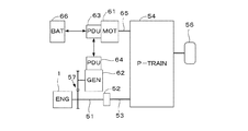
図1は本発明の一実施形態にかかる車両を駆動する車両駆動装置の構成を示す図であり、この車両駆動装置は、駆動源としての内燃機関(以下「エンジン」という)1及びモータ61と、エンジン1及び高圧バッテリ66の電力により駆動される発電機62と、エンジン1及びモータ61の駆動力を駆動輪56に伝達する駆動力伝達機構54とを備えている。エンジン1の出力軸51は、クラッチ52、駆動軸53を介して駆動力伝達機構54に接続され、モータ61の出力軸65は直接駆動力伝達機構54に接続されている。モータ61は回生動作を行うときは発電機として作動する。駆動力伝達機構54は差動ギヤ機構を含む。
Embodiments of the present invention will be described below with reference to the drawings.
FIG. 1 is a diagram showing a configuration of a vehicle drive device that drives a vehicle according to an embodiment of the present invention. The vehicle drive device includes an internal combustion engine (hereinafter referred to as “engine”) 1 and a
エンジン1の出力軸51は、ギヤ対57を介して発電機62に接続されており、発電機62はエンジン1の駆動力により発電を行う。モータ61及び発電機62は、それぞれパワードライビングユニット(以下「PDU」という)63,64に電気的に接続されており、PDU63はPDU64及び高圧バッテリ66に接続されている。PDU63,64は、モータ制御用電子制御ユニット(図示せず)に接続され、それぞれモータ61及び発電機62の動作制御を行うとともに、高圧バッテリ66の充電及び放電の制御を行う。
The
図1に示す車両駆動装置によれば、下記の運転モードによる運転が行われる。
1)第1運転モード
高圧バッテリ66から供給される電力によって駆動されるモータ61の出力で走行する運転モードであり、第1運転モードでは、エンジン1は停止し、クラッチ52は解放(非締結)状態とされる。第1運転モードは、電動機駆動モードともいう。
According to the vehicle drive device shown in FIG. 1, driving in the following operation mode is performed.
1) 1st operation mode It is the operation mode which drive | works with the output of the
2)第2運転モード
クラッチ52を解放状態として、エンジン1を作動させて発電機62による発電を行い、その発電電力によって駆動されるモータ61の出力で走行する運転モードである。第2運転モードでは、発電機62による発電電力がモータ61の消費電力より大きいときは、余剰電力によって高圧バッテリ66の充電が行われる一方、発電機62による発電電力がモータ61の消費電力より小さいときは、不足電力は高圧バッテリ66の放電によって補われる。
2) Second operation mode This is an operation mode in which the clutch 52 is disengaged, the
3)第3運転モード
主としてエンジン1の出力によって走行する運転モードである。第3運転モードでは、クラッチ52が締結されてエンジン1の出力が駆動力伝達機構54に入力され、駆動輪56に伝達される。第3運転モードでは、エンジン負荷の増減によって、余剰トルクまたは不足トルクが発生するので、余剰トルクが発生したときはモータ61を発電機として作動させて高圧バッテリ66の充電が行われる一方、不足トルクが発生したときはモータ61の出力によってエンジン出力のアシストが行われる。
3) Third operation mode This is an operation mode in which the vehicle travels mainly by the output of the
第2及び第3運転モードは、エンジン駆動モードともいう。エンジン駆動モードでは、所定アイドリングストップ実行条件が成立したときは、エンジン1の自動停止(以下「アイドリングストップ」という)を行う。所定アイドリングストップ実行条件は、例えば車速VPが所定車速以下であること、アクセルペダルが踏み込まれていない状態であること、ブレーキペダルが踏み込まれていること、高圧バッテリ66の残電荷量が所定量以上であること、エンジン冷却水温が所定水温以上であってエンジン1の暖機が完了していること等の条件が満たされるときに成立する。
The second and third operation modes are also called engine drive modes. In the engine drive mode, when a predetermined idling stop execution condition is satisfied, the
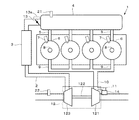
図2はエンジン1の構成を模式的に示す図であり、エンジン1は、4つの気筒6を有し、気筒6の燃焼室内に燃料を直接噴射する直噴エンジンであり、各気筒6には燃料噴射弁7、点火プラグ8、及び吸気弁及び排気弁(図示せず)が設けられている。
FIG. 2 is a diagram schematically showing the configuration of the
エンジン1は、吸気通路2、排気通路10、及びターボチャージャ(過給機)12を備えている。吸気通路2は、サージタンク4に接続され、サージタンク4は吸気マニホールド5を介して各気筒6の燃焼室に接続されている。吸気通路2には、加圧された空気を冷却するためのインタークーラ3及びスロットル弁13が設けられ、スロットル弁13は、スロットルアクチュエータ13aによって駆動可能に構成されている。サージタンク4には、吸気圧PBを検出する吸気圧センサ21が設けられ、吸気通路2には吸入空気流量GAIRを検出する吸入空気流量センサ22が設けられている。
The
ターボチャージャ12は、排気通路9に設けられ、排気の運動エネルギにより回転駆動されるタービン121と、シャフト122を介してタービン121に連結されたコンプレッサ123とを備えている。コンプレッサ123は、吸気通路2に設けられ、エンジン1に吸入される空気の加圧(圧縮)を行う。
The
エンジン1の各気筒6の燃焼室は排気マニホールド9を介して排気通路10に接続されている。排気通路10には、タービン121をバイパスするバイパス通路11が接続されており、バイパス通路11には、バイパス通路11を通過する排気の流量を制御するウエストゲート弁(以下「WG弁」という)14が設けられている。
A combustion chamber of each
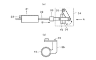
図3は、WG弁14の弁体15を駆動する駆動機構を模式的に示す図であり、モータ31、ロッド32、遮熱部材33、及びリンク機構34によって弁体15が開閉駆動される。図3(b)は、図3(a)の矢印Aの方向からみた図である。リンク機構34は弁体15が固定された保持部材36が回転軸35を中心として回動可能に構成されている。
FIG. 3 is a diagram schematically showing a drive mechanism for driving the
図3(a)は、WG弁14が全閉である状態、すなわちバイパス通路11を閉塞している状態に対応する。モータ31が回転駆動されると、ロッド32が図3(a)において、矢印Bで示す直線方向に移動し、リンク機構34の回転軸35を中心として保持部材36及び弁体15が矢印Cで示すように回動し、WG弁14が開弁する。WG弁14の弁開度センサ23が、ロッド32の近傍に配置されており、ロッド32の直線方向(矢印B方向)の位置を検出することによって、WG弁14の開度(以下「WG開度」という)WGOが検出される。なお、本実施形態ではWG弁14は、バイパス通路11がタービン121の下流側で排気通路10に開口する開口部を開閉するように構成されている。
FIG. 3A corresponds to a state where the
図4は、エンジン1の制御を行う制御系の構成を示すブロック図であり、電子制御ユニット(以下「ECU」という)30には、上述した吸気圧センサ21、吸入空気流量センサ22、及び弁開度センサ23の他、エンジン1の回転数NEを検出するエンジン回転数センサ24、エンジン1により駆動される車両のアクセルペダル(図示せず)の踏み込み量(以下「アクセルペダル操作量」という)APを検出するアクセルセンサ25、エンジン冷却水温TWを検出する冷却水温センサ26、及び図示しない他のセンサが接続されており、これらのセンサの検出信号がECU30に供給される。ECU30の出力側には、燃料噴射弁7、点火プラグ8、スロットルアクチュエータ13a、及びWG弁14の駆動機構のモータ31が接続されている。
FIG. 4 is a block diagram showing the configuration of a control system that controls the
ECU30は、エンジン運転状態(主としてエンジン回転数NE及び要求トルクTRQD)に応じて、燃料噴射弁7による燃料噴射制御、点火プラグ8による点火制御、WG弁14によるタービン駆動制御、スロットル弁13による吸入空気量制御を行う。要求トルクTRQDは、主としてアクセルペダル操作量APに応じて算出され、アクセルペダル操作量APが増加するほど増加するように算出される。
The
タービン駆動制御においては、検出されるWG開度WGOが目標開度WGCMDと一致するようにモータ31の駆動制御が行われる。WG弁14の実開度WGAを目標開度WGCMDに正確に一致させるためには、検出されるWG開度WGOの精度を高める必要がある。
In the turbine drive control, drive control of the
上述したように弁開度センサ23は、弁体15の位置を直接検出するものではないため、検出されるWG開度WGOは以下に示す多くの誤差を含んでいる。
1)組み付け誤差EA:WG弁14及びその駆動機構をエンジン1に組み付ける際に発生する誤差
2)摩耗誤差EF:駆動機構を構成する部品の摩耗による誤差
3)たわみ誤差ET:駆動機構を構成する部品のたわみによる誤差
4)温度依存誤差EH:駆動機構を構成する部品の温度変化による伸縮によって発生する誤差
5)計測誤差EM:弁開度センサ23やECU30で発生する誤差
6)位置ずれ誤差EP:駆動機構にわずかに存在する構成部品相互間の相対的な位置ずれ(いわゆる「がたつき」)に起因する誤差(車両走行中の振動によって変化する微少開度量に相当する誤差)
As described above, since the
1) Assembly error EA: Error generated when the
そこで、弁体15が全閉位置に到達したときに弁開度センサ23によって検出される弁開度WGFCを基準開度として学習する全閉開度学習を適時実行し、WG弁開度制御では、弁開度センサ23の出力開度WGDETから基準開度WGFCを減算した開度をWG開度WGOとして検出する。学習実行直後においては、計測誤差EMの一部(AD変換に伴って発生する誤差)及び位置ずれ誤差EP以外の誤差は除去されるので、WG開度WGOはほぼ実開度WGAと一致する。温度依存誤差EHは、WG弁14及びその近傍の温度の変化に依存して変化するため、学習実行後の温度変化が大きい場合には、再度全閉開度学習を行う前は、WG開度WGOと実開度WGAとの差が増加する。
Therefore, a fully closed opening learning is performed in a timely manner in which the valve opening WGFC detected by the
本実施形態では、イグニッションスイッチがオンされた直後(エンジン1の低温時)における低温時学習、及びエンジン1の動作中において実行可能なタイミングにおける作動時学習が行われる。低温時学習を行うことによって、組み付け誤差EA及び摩耗誤差EFを除くことができ、さらに作動時学習を行うことによって温度依存誤差EHを除くことができる。
In the present embodiment, learning at a low temperature immediately after the ignition switch is turned on (when the
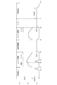
図5は、本実施形態におけるWG開度WGOの制御を説明するためのタイムチャートであり、図5(a)〜(c)には、それぞれ車両の運転状態、エンジン回転数NE、及びWG開度WGOの推移が示されている。 FIG. 5 is a time chart for explaining the control of the WG opening degree WGO in the present embodiment. FIGS. 5A to 5C show the driving state of the vehicle, the engine speed NE, and the WG opening, respectively. The change of degree WGO is shown.
時刻t0にイグニッションスイッチがオンされると、WG弁14の全閉開度学習(低温時学習)が行われる。時刻t1からエンジン駆動モードが開始され、エンジン回転数NEの上昇に伴ってターボチャージャ12による過給が行われる。時刻t2では、過給圧を低下させるためにWG弁14が開弁される。その後全閉状態に移行した時刻t3において再度全閉位置学習(作動時学習)が行われる。過給運転の後は、燃料カット運転(F/C)が行われ、時刻t4から電動機駆動モードに移行する。このときWG弁14は所定開度WGX(例えば全開開度の13%程度に相当する開度)まで開弁される。
When the ignition switch is turned on at time t0, the fully closed opening degree learning (learning at low temperature) of the
具体的には、目標開度WGCMDを所定開度WGXに設定して、検出されるWG開度WGOが目標開度WGCMDと一致するようにモータ31が駆動される。WG開度WGOが目標開度WGCMDに到達するとモータ31の通電は停止される。
Specifically, the target opening degree WGCMD is set to a predetermined opening degree WGX, and the
所定開度WGXは、弁開度センサ23の出力開度WGDETと、実開度WGAとの誤差が想定される最大値EMAXとなった状態において、弁体15が通路内壁に接触しない非接触条件を満たすように設定される。具体的には、所定開度WGXが、誤差の最大値EMAXを全閉開度(=0)に加算した閾値WGTH以上であるという非接触条件を満たすように設定され、かつ非接触条件を満たす最小開度である閾値WGTHに設定される。すなわち、非接触条件は下記式(1)で示され、所定開度WGXは下記式(2)で与えられる。
WGX≧WGTH=0+EMAX (1)
WGX=WGTH=0+EMAX (2)
The predetermined opening WGX is a non-contact condition in which the
WGX ≧ WGTH = 0 + EMAX (1)
WGX = WGTH = 0 + EMAX (2)
最大値EMAXは、低温時学習によって除去される組み付け誤差EA及び摩耗誤差EF以外の誤差、すなわち、たわみ誤差ET、温度依存誤差EH、計測誤差EM、及び位置ずれ誤差EPの和の最大値であり、予め実験によって決定される。 The maximum value EMAX is the maximum value of errors other than the assembly error EA and wear error EF that are removed by learning at low temperatures, that is, the sum of the deflection error ET, temperature-dependent error EH, measurement error EM, and misalignment error EP. , Determined in advance by experiment.
時刻t5からエンジン駆動モードへ移行する。そのとき目標開度WGCMDを全閉開度「0」に設定してWG弁14を閉弁する動作と、エンジン1の始動とが並行して実行される。時刻t6の少し前から燃料カット運転が実行され、時刻t6からアイドリングストップが開始される。アイドリングストップの開始時には、目標開度WGCMDが所定開度WGXに設定され、WG開度WGOが目標開度WGCMDに到達するとモータ31の通電が停止される。
The engine drive mode is shifted from time t5. At that time, the operation of setting the target opening WGCMD to the fully closed opening “0” and closing the
時刻t7においてイグニッションスイッチがオフされる。その時点から一定待機時間TWAIT経過後の時刻t8において目標開度WGCMDが「0」に設定され、WG弁14は閉弁される。
At time t7, the ignition switch is turned off. The target opening WGCMD is set to “0” at time t8 after the fixed waiting time TWAIT has elapsed from that time, and the
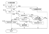
図6は、上述したWG弁14の開度制御を実行する処理のフローチャートである。この処理は、ECU30において一定時間毎に実行される。
ステップS11では、学習フラグFLRNが「1」であるか否かを判別する。学習フラグFLRNは、上述したようにイグニッションスイッチがオンされた直後やターボチャージャ作動中においてWG弁14を開弁したときなどにおいて「1」に設定される。ステップS11の答が肯定(YES)であるときは、全閉開度学習を実行する(ステップS17)。
FIG. 6 is a flowchart of a process for executing the above-described opening degree control of the
In step S11, it is determined whether or not the learning flag FLRN is “1”. The learning flag FLRN is set to “1” as described above immediately after the ignition switch is turned on or when the
ステップS11の答が否定(NO)であるときは、電動機駆動モードフラグFEVが「1」であるか否かを判別する(ステップS12)。この答が肯定(YES)であるときは、目標開度WGCMDを所定開度WGXに設定し(ステップS15)、WG開度WGOが目標開度WGCMDと一致するようにモータ31を駆動し、WG開度WGOが目標開度WGCMDに一致するとモータ31への駆動信号の出力を停止する。
If the answer to step S11 is negative (NO), it is determined whether or not an electric motor drive mode flag FEV is “1” (step S12). If the answer is affirmative (YES), the target opening degree WGCMD is set to a predetermined opening degree WGX (step S15), the
ステップS12の答が否定(NO)であって、電動機駆動モードではないときは、イグニッションスイッチがオフされたか否かを判別する(ステップS13)。この答が否定(NO)であるときは、アイドリングストップフラグFISが「1」であるか否かを判別する(ステップS14)。アイドリングストップフラグFISは、アイドリングストップ実行条件が成立するとき「1」に設定される。ステップS14の答が肯定(YES)であって、アイドリングストップを実行するときは、ステップS15に進む。 If the answer to step S12 is negative (NO), and the motor drive mode is not set, it is determined whether or not the ignition switch is turned off (step S13). If this answer is negative (NO), it is determined whether or not an idling stop flag FIS is “1” (step S14). The idling stop flag FIS is set to “1” when the idling stop execution condition is satisfied. If the answer to step S14 is affirmative (YES), and the idling stop is executed, the process proceeds to step S15.
アイドリングストップフラグFISが「0」であるときは、ステップS16に進み、通常制御、すなわちエンジン1の運転状態に応じたWG開度制御を実行する。
イグニッションスイッチがオフされるとステップS13からステップS18に進み、イグニッションスイッチがオフされた時点が所定待機時間TWAITが経過したか否かを判別する。ステップS18の答が否定(NO)である間は処理を終了し、肯定(YES)となると目標開度WGCMDを「0」に設定し、WG弁14を全閉開度に制御する(ステップS19)。
When the idling stop flag FIS is “0”, the process proceeds to step S16, and normal control, that is, WG opening degree control according to the operating state of the
When the ignition switch is turned off, the process proceeds from step S13 to step S18, and it is determined whether or not the predetermined waiting time TWAIT has elapsed from the time when the ignition switch was turned off. If the answer to step S18 is negative (NO), the process is terminated. If the answer is affirmative (YES), the target opening degree WGCMD is set to “0” and the
以上のように本実施形態では、モータ61のみを駆動源として車両が駆動される電動機駆動モードでの走行中に、エンジン1が自動停止されるとともに、WG弁14の目標開度WGCMDが所定開度WGXに設定され、弁開度センサ23によって検出されるWG開度WGOが目標開度WGCMDと一致するようにWG弁14が制御される。その際、所定開度WGXは、WG開度WGOと、実開度WGAとの誤差が想定される最大値EMAXとなった状態において、実開度WGAが全閉開度「0」以下とならない非接触条件を満たすように設定されるので、WG弁14の弁体15がバイパス通路あるいは排気通路の内壁に接触してノイズが発生することを防止できる。また、検出されるWG開度WGOが目標開度WGCMDと一致している状態では、WG弁14の弁体15を駆動するモータ31の通電が停止されるので、電磁波ノイズの発生を防止することができる。
As described above, in the present embodiment, the
また非接触条件は、所定開度WGXが、想定される検出誤差の最大値EMAXを全閉開度「0」に加算した閾値WGTH以上である条件とされ、所定開度WGXは、非接触条件を満たす開度範囲の最小値、すなわち閾値WGTHに設定されるので、弁体15が通路内壁に接触することを確実に防止するとともに、エンジン1の再始動時においてウエストゲート弁14を迅速に全閉開度「0」に制御することができる。また、エンジン1の再始動時における閉弁動作時に、完全に閉弁するまでの期間にWG弁14を通過する排気流量は僅かであって、電動機駆動モードにおいて開弁することによる悪影響(例えば応答特性の悪化)を無視できる程度とすることができる。
The non-contact condition is a condition in which the predetermined opening WGX is equal to or greater than a threshold value WGTH obtained by adding the maximum value EMAX of the assumed detection error to the fully closed opening “0”, and the predetermined opening WGX is a non-contact condition. Is set to the minimum value of the opening range that satisfies the above condition, that is, the threshold value WGTH, so that the
またWG弁14はターボチャージャ12の近傍に配置され、WG弁14及びその駆動機構の温度変化が大きいので、温度変化に起因する温度依存誤差EHが大きい。また車両走行中の振動によって、部品相互間の相対的な位置ずれに起因する位置ずれ誤差EP(いわゆる「がたつき」)があると、車両停止中は弁体15が通路内壁に接触していなくても、走行中に振動によって接触する可能性がある。したがって、WG開度WGOに含まれる誤差として温度依存誤差及び「がたつき」による誤差を含めることによって、ノイズの発生を確実に防止できる。
Further, since the
また電動機駆動モードを終了するときに、エンジン1の再始動開始前に目標開度WGCMDが全閉開度に設定され、エンジン1の再始動と、WG弁14の閉弁動作とが並行して行われるので、エンジン1の再始動を円滑かつ迅速に行うことできる。
When the motor drive mode is ended, the target opening WGCMD is set to the fully closed opening before the restart of the
本実施形態では、ECU30、モータ制御用電子制御ユニット(図示せず)及びこれらの制御ユニットに接続されるセンサによって車両の制御装置が構成される。また、弁開度センサ23が開度検出手段に相当し、ECU30が一時停止手段及び弁制御手段を構成し、WG弁14の駆動機構が弁制御手段の一部を構成する。
In the present embodiment, the
なお本発明は上述した実施形態に限るものではなく、種々の変形が可能である。例えば、上述した実施形態では所定開度WGXを非接触条件を満たす開度範囲の最小値(WGTH)に設定するようにしたが、最小値より大きな値に設定してもよい。 The present invention is not limited to the embodiment described above, and various modifications can be made. For example, in the above-described embodiment, the predetermined opening WGX is set to the minimum value (WGTH) of the opening range that satisfies the non-contact condition, but may be set to a value larger than the minimum value.
また、上述した実施形態では、エンジン1が直噴4気筒エンジンである例を示したが、本願発明はエンジンの気筒数や燃料供給装置の構成にかかわらず適用可能であり、エンジン1はディーゼルエンジンであってもよい。
In the above-described embodiment, the example in which the
1 内燃機関
10 排気通路
11 バイパス通路
12 ターボチャージャ(過給機)
121 タービン
123 コンプレッサ
14 ウエストゲート弁
23 弁開度センサ(開度検出手段)
30 電子制御ユニット(一時停止手段、弁制御手段)
31 モータ(弁制御手段)
61 モータ(電動機)
1
121
30 Electronic control unit (temporary stop means, valve control means)
31 Motor (valve control means)
61 Motor (electric motor)
Claims (4)
前記車両は前記電動機のみを駆動源とする電動機駆動モードでの走行が可能であり、
前記電動機駆動モードでの走行中に前記機関を自動停止させる一時停止手段と、
前記ウエストゲート弁の開度を検出する開度検出手段と、
前記電動機駆動モードにおいて前記ウエストゲート弁の目標開度を所定開度に設定し、前記開度検出手段により検出される開度が前記目標開度と一致するように前記ウエストゲート弁を制御する弁制御手段とを備え、
前記所定開度は、前記検出される開度と、前記ウエストゲート弁の実開度との誤差が想定される最大値となった状態において、前記実開度が全閉開度以下とならない非接触条件を満たすように設定されることを特徴とする車両の制御装置。 A control apparatus for a vehicle including an internal combustion engine and an electric motor as a drive source, wherein the engine includes a turbine provided in an exhaust passage, and a compressor that is rotationally driven by the turbine and pressurizes intake air of the engine. And a vehicle control device comprising a wastegate valve provided in a bypass passage that bypasses the turbine,
The vehicle is capable of traveling in an electric motor drive mode using only the electric motor as a drive source,
A temporary stop means for automatically stopping the engine during traveling in the electric motor drive mode;
An opening degree detecting means for detecting an opening degree of the waste gate valve;
A valve that controls the wastegate valve such that the target opening of the wastegate valve is set to a predetermined opening in the motor drive mode, and the opening detected by the opening detection means coincides with the target opening Control means,
The predetermined opening is a non-opening position where the actual opening is not less than or equal to a fully closed opening in a state where an error between the detected opening and the actual opening of the wastegate valve is assumed to be a maximum value. A control device for a vehicle, wherein the control device is set to satisfy a contact condition.
前記所定開度は、前記非接触条件を満たす最小開度である前記閾値に設定されることを特徴とする請求項1に記載の車両の制御装置。 The non-contact condition is a condition that the predetermined opening is not less than a threshold obtained by adding the maximum value of the assumed error to the fully closed opening,
The vehicle control device according to claim 1, wherein the predetermined opening is set to the threshold that is a minimum opening satisfying the non-contact condition.
Priority Applications (3)
| Application Number | Priority Date | Filing Date | Title |
|---|---|---|---|
| JP2016013911A JP6232085B2 (en) | 2016-01-28 | 2016-01-28 | Vehicle control device |
| US15/384,318 US10502123B2 (en) | 2016-01-28 | 2016-12-20 | Control device for vehicle, and control method for vehicle |
| CN201710057333.1A CN107010047B (en) | 2016-01-28 | 2017-01-26 | The control device of vehicle |
Applications Claiming Priority (1)
| Application Number | Priority Date | Filing Date | Title |
|---|---|---|---|
| JP2016013911A JP6232085B2 (en) | 2016-01-28 | 2016-01-28 | Vehicle control device |
Publications (2)
| Publication Number | Publication Date |
|---|---|
| JP2017132360A JP2017132360A (en) | 2017-08-03 |
| JP6232085B2 true JP6232085B2 (en) | 2017-11-15 |
Family
ID=59386505
Family Applications (1)
| Application Number | Title | Priority Date | Filing Date |
|---|---|---|---|
| JP2016013911A Active JP6232085B2 (en) | 2016-01-28 | 2016-01-28 | Vehicle control device |
Country Status (3)
| Country | Link |
|---|---|
| US (1) | US10502123B2 (en) |
| JP (1) | JP6232085B2 (en) |
| CN (1) | CN107010047B (en) |
Families Citing this family (1)
| Publication number | Priority date | Publication date | Assignee | Title |
|---|---|---|---|---|
| JP2020041516A (en) | 2018-09-13 | 2020-03-19 | トヨタ自動車株式会社 | Control device of supercharger |
Family Cites Families (10)
| Publication number | Priority date | Publication date | Assignee | Title |
|---|---|---|---|---|
| JP3429226B2 (en) * | 1999-07-23 | 2003-07-22 | 本田技研工業株式会社 | Control device for vehicle power transmission |
| JP2007298005A (en) * | 2006-05-02 | 2007-11-15 | Suzuki Motor Corp | Supercharging pressure control device for internal combustion engine |
| BR112013006039B1 (en) * | 2010-11-12 | 2021-12-28 | Aisin Seiki Kabushiki Kaisha | CONTROL VALVE |
| US8978378B2 (en) * | 2011-10-20 | 2015-03-17 | Ford Global Technologies, Llc | Method and system for reducing turbocharger noise during cold start |
| DE102013207437B4 (en) * | 2012-05-01 | 2020-06-04 | GM Global Technology Operations LLC (n. d. Ges. d. Staates Delaware) | Method of controlling engine torque to prevent driveline jerking during a downshift when a throttle valve is closed |
| JP6132092B2 (en) | 2013-05-23 | 2017-05-24 | 三菱自動車工業株式会社 | Engine control device |
| JP6284378B2 (en) * | 2014-01-31 | 2018-02-28 | ダイハツ工業株式会社 | Internal combustion engine with a supercharger |
| JP6123707B2 (en) * | 2014-03-04 | 2017-05-10 | 株式会社デンソー | Control device for internal combustion engine |
| JP6044572B2 (en) * | 2014-03-19 | 2016-12-14 | マツダ株式会社 | Control device for turbocharged engine |
| JP6173523B1 (en) * | 2016-04-26 | 2017-08-02 | 三菱電機株式会社 | Control device for internal combustion engine |
-
2016
- 2016-01-28 JP JP2016013911A patent/JP6232085B2/en active Active
- 2016-12-20 US US15/384,318 patent/US10502123B2/en active Active
-
2017
- 2017-01-26 CN CN201710057333.1A patent/CN107010047B/en active Active
Also Published As
| Publication number | Publication date |
|---|---|
| JP2017132360A (en) | 2017-08-03 |
| CN107010047A (en) | 2017-08-04 |
| CN107010047B (en) | 2019-05-28 |
| US20170218835A1 (en) | 2017-08-03 |
| US10502123B2 (en) | 2019-12-10 |
Similar Documents
| Publication | Publication Date | Title |
|---|---|---|
| JP5847857B2 (en) | Reference position learning device for a valve of an internal combustion engine | |
| US9008878B2 (en) | Control device for hybrid vehicle including exhaust-gas driven generator and method of controlling hybrid vehicle including exhaust-gas driven generator | |
| US9022001B2 (en) | Starter control systems and methods for engine rockback | |
| JP4941534B2 (en) | Wastegate valve control device for internal combustion engine | |
| CN108087107B (en) | Control device for internal combustion engine | |
| US8453620B2 (en) | Systems and methods for improved engine start-stop response | |
| US10415460B2 (en) | Control device for an internal combustion engine | |
| US11519353B2 (en) | Method of operating an internal combustion engine | |
| JP6232085B2 (en) | Vehicle control device | |
| JP4086005B2 (en) | Warm-up control method of low compression ratio engine in diesel hybrid vehicle | |
| JP5615328B2 (en) | Control device for vehicle drive device | |
| JP4099160B2 (en) | Motor torque control method for hybrid vehicle | |
| WO2017086420A1 (en) | Hybrid vehicle and control method for same | |
| JP6505073B2 (en) | Control device for internal combustion engine | |
| JP6505071B2 (en) | Fully closed position learning device for waste gate valve | |
| JP6333314B2 (en) | Vehicle control device | |
| JP6672784B2 (en) | Engine control device | |
| JP2019132185A (en) | Controller of internal combustion engine | |
| JP7087440B2 (en) | Vehicle control unit | |
| JP6289901B2 (en) | Vehicle start control device, start control method, and hybrid engine with supercharger | |
| US20200318588A1 (en) | Hybrid vehicle and method of diagnosing abnormal condition of hybrid vehicle | |
| JP5565378B2 (en) | Internal combustion engine control system | |
| CN107683367B (en) | Vehicle-mounted control device | |
| JP2007327414A (en) | Engine system control device for vehicle | |
| JP2011255746A (en) | Device for control of hybrid vehicle |
Legal Events
| Date | Code | Title | Description |
|---|---|---|---|
| TRDD | Decision of grant or rejection written | ||
| A01 | Written decision to grant a patent or to grant a registration (utility model) |
Free format text: JAPANESE INTERMEDIATE CODE: A01 Effective date: 20171017 |
|
| A61 | First payment of annual fees (during grant procedure) |
Free format text: JAPANESE INTERMEDIATE CODE: A61 Effective date: 20171020 |
|
| R150 | Certificate of patent or registration of utility model |
Ref document number: 6232085 Country of ref document: JP Free format text: JAPANESE INTERMEDIATE CODE: R150 |