JP6230912B2 - Characteristic determination device for determining the characteristics of an object - Google Patents
Characteristic determination device for determining the characteristics of an object Download PDFInfo
- Publication number
- JP6230912B2 JP6230912B2 JP2013533310A JP2013533310A JP6230912B2 JP 6230912 B2 JP6230912 B2 JP 6230912B2 JP 2013533310 A JP2013533310 A JP 2013533310A JP 2013533310 A JP2013533310 A JP 2013533310A JP 6230912 B2 JP6230912 B2 JP 6230912B2
- Authority
- JP
- Japan
- Prior art keywords
- sensing data
- ultrasonic
- energy supply
- optical
- energy
- Prior art date
- Legal status (The legal status is an assumption and is not a legal conclusion. Google has not performed a legal analysis and makes no representation as to the accuracy of the status listed.)
- Expired - Fee Related
Links
- 230000003287 optical effect Effects 0.000 claims description 185
- 238000012512 characterization method Methods 0.000 claims description 157
- 238000002679 ablation Methods 0.000 claims description 131
- 238000002604 ultrasonography Methods 0.000 claims description 92
- 238000001228 spectrum Methods 0.000 claims description 72
- 238000000034 method Methods 0.000 claims description 60
- 239000013307 optical fiber Substances 0.000 claims description 55
- 238000004590 computer program Methods 0.000 claims description 10
- 238000003860 storage Methods 0.000 claims description 9
- 210000001519 tissue Anatomy 0.000 description 145
- 239000000523 sample Substances 0.000 description 90
- 239000013598 vector Substances 0.000 description 68
- 210000005003 heart tissue Anatomy 0.000 description 31
- 230000003902 lesion Effects 0.000 description 23
- 238000005259 measurement Methods 0.000 description 21
- XLYOFNOQVPJJNP-UHFFFAOYSA-N water Substances O XLYOFNOQVPJJNP-UHFFFAOYSA-N 0.000 description 20
- 238000007621 cluster analysis Methods 0.000 description 17
- 238000002347 injection Methods 0.000 description 17
- 239000007924 injection Substances 0.000 description 17
- 230000010412 perfusion Effects 0.000 description 17
- 239000012530 fluid Substances 0.000 description 14
- 230000008859 change Effects 0.000 description 13
- 230000033001 locomotion Effects 0.000 description 13
- 238000004422 calculation algorithm Methods 0.000 description 11
- 210000004369 blood Anatomy 0.000 description 10
- 239000008280 blood Substances 0.000 description 10
- 230000006378 damage Effects 0.000 description 9
- 230000006870 function Effects 0.000 description 9
- 238000010521 absorption reaction Methods 0.000 description 8
- 230000001678 irradiating effect Effects 0.000 description 8
- 238000012545 processing Methods 0.000 description 8
- 238000002594 fluoroscopy Methods 0.000 description 7
- 230000035515 penetration Effects 0.000 description 7
- 238000010586 diagram Methods 0.000 description 6
- 239000000835 fiber Substances 0.000 description 6
- 239000000203 mixture Substances 0.000 description 6
- 230000008569 process Effects 0.000 description 6
- 230000004913 activation Effects 0.000 description 5
- 230000008081 blood perfusion Effects 0.000 description 5
- 230000001419 dependent effect Effects 0.000 description 5
- 210000000056 organ Anatomy 0.000 description 5
- 238000011524 similarity measure Methods 0.000 description 5
- 230000036962 time dependent Effects 0.000 description 5
- 238000012935 Averaging Methods 0.000 description 4
- 230000002262 irrigation Effects 0.000 description 4
- 238000003973 irrigation Methods 0.000 description 4
- 235000019557 luminance Nutrition 0.000 description 4
- 229910052751 metal Inorganic materials 0.000 description 4
- 239000002184 metal Substances 0.000 description 4
- 230000004044 response Effects 0.000 description 4
- 238000011282 treatment Methods 0.000 description 4
- 238000011298 ablation treatment Methods 0.000 description 3
- 238000000149 argon plasma sintering Methods 0.000 description 3
- 239000010410 layer Substances 0.000 description 3
- 230000004807 localization Effects 0.000 description 3
- 230000003595 spectral effect Effects 0.000 description 3
- 239000002344 surface layer Substances 0.000 description 3
- 102000001554 Hemoglobins Human genes 0.000 description 2
- 108010054147 Hemoglobins Proteins 0.000 description 2
- 241001465754 Metazoa Species 0.000 description 2
- 230000005856 abnormality Effects 0.000 description 2
- 238000013153 catheter ablation Methods 0.000 description 2
- 230000001112 coagulating effect Effects 0.000 description 2
- 239000011248 coating agent Substances 0.000 description 2
- 238000000576 coating method Methods 0.000 description 2
- 238000002591 computed tomography Methods 0.000 description 2
- 230000008602 contraction Effects 0.000 description 2
- 230000000694 effects Effects 0.000 description 2
- 238000011156 evaluation Methods 0.000 description 2
- 238000000605 extraction Methods 0.000 description 2
- 238000001914 filtration Methods 0.000 description 2
- 238000010438 heat treatment Methods 0.000 description 2
- 239000007788 liquid Substances 0.000 description 2
- 238000002595 magnetic resonance imaging Methods 0.000 description 2
- 239000003550 marker Substances 0.000 description 2
- 230000001404 mediated effect Effects 0.000 description 2
- 208000010125 myocardial infarction Diseases 0.000 description 2
- 238000000513 principal component analysis Methods 0.000 description 2
- 210000003492 pulmonary vein Anatomy 0.000 description 2
- 230000002829 reductive effect Effects 0.000 description 2
- 231100000241 scar Toxicity 0.000 description 2
- 235000020083 shōchū Nutrition 0.000 description 2
- 239000000243 solution Substances 0.000 description 2
- 238000004611 spectroscopical analysis Methods 0.000 description 2
- 206010003658 Atrial Fibrillation Diseases 0.000 description 1
- VYZAMTAEIAYCRO-UHFFFAOYSA-N Chromium Chemical compound [Cr] VYZAMTAEIAYCRO-UHFFFAOYSA-N 0.000 description 1
- 238000000342 Monte Carlo simulation Methods 0.000 description 1
- 238000001069 Raman spectroscopy Methods 0.000 description 1
- FAPWRFPIFSIZLT-UHFFFAOYSA-M Sodium chloride Chemical compound [Na+].[Cl-] FAPWRFPIFSIZLT-UHFFFAOYSA-M 0.000 description 1
- 230000002411 adverse Effects 0.000 description 1
- 210000001557 animal structure Anatomy 0.000 description 1
- 206010003119 arrhythmia Diseases 0.000 description 1
- 230000008901 benefit Effects 0.000 description 1
- 230000015572 biosynthetic process Effects 0.000 description 1
- 230000017531 blood circulation Effects 0.000 description 1
- 210000001124 body fluid Anatomy 0.000 description 1
- 229910052804 chromium Inorganic materials 0.000 description 1
- 239000011651 chromium Substances 0.000 description 1
- 238000005253 cladding Methods 0.000 description 1
- 239000004020 conductor Substances 0.000 description 1
- 238000001816 cooling Methods 0.000 description 1
- 238000012937 correction Methods 0.000 description 1
- 238000013500 data storage Methods 0.000 description 1
- 238000009795 derivation Methods 0.000 description 1
- 238000001514 detection method Methods 0.000 description 1
- 238000009543 diffuse optical tomography Methods 0.000 description 1
- 239000006185 dispersion Substances 0.000 description 1
- 210000003743 erythrocyte Anatomy 0.000 description 1
- 230000005284 excitation Effects 0.000 description 1
- 238000003384 imaging method Methods 0.000 description 1
- 238000001727 in vivo Methods 0.000 description 1
- 230000000977 initiatory effect Effects 0.000 description 1
- 238000003064 k means clustering Methods 0.000 description 1
- 230000000670 limiting effect Effects 0.000 description 1
- 150000002632 lipids Chemical class 0.000 description 1
- 238000004599 local-density approximation Methods 0.000 description 1
- 230000005389 magnetism Effects 0.000 description 1
- 239000000463 material Substances 0.000 description 1
- 239000011159 matrix material Substances 0.000 description 1
- 238000012986 modification Methods 0.000 description 1
- 230000004048 modification Effects 0.000 description 1
- 238000012544 monitoring process Methods 0.000 description 1
- 210000003205 muscle Anatomy 0.000 description 1
- 238000012633 nuclear imaging Methods 0.000 description 1
- 238000012634 optical imaging Methods 0.000 description 1
- 230000008520 organization Effects 0.000 description 1
- 238000013021 overheating Methods 0.000 description 1
- 230000001314 paroxysmal effect Effects 0.000 description 1
- 230000036961 partial effect Effects 0.000 description 1
- 210000005259 peripheral blood Anatomy 0.000 description 1
- 239000011886 peripheral blood Substances 0.000 description 1
- 229920000052 poly(p-xylylene) Polymers 0.000 description 1
- 229920000642 polymer Polymers 0.000 description 1
- 229920000306 polymethylpentene Polymers 0.000 description 1
- 239000011116 polymethylpentene Substances 0.000 description 1
- 230000001737 promoting effect Effects 0.000 description 1
- 238000011002 quantification Methods 0.000 description 1
- 238000007674 radiofrequency ablation Methods 0.000 description 1
- 230000009467 reduction Effects 0.000 description 1
- 238000001055 reflectance spectroscopy Methods 0.000 description 1
- 230000002441 reversible effect Effects 0.000 description 1
- 238000005070 sampling Methods 0.000 description 1
- 230000011218 segmentation Effects 0.000 description 1
- 238000005204 segregation Methods 0.000 description 1
- 229910052709 silver Inorganic materials 0.000 description 1
- 239000004332 silver Substances 0.000 description 1
- 239000011780 sodium chloride Substances 0.000 description 1
- 239000007787 solid Substances 0.000 description 1
- 238000007619 statistical method Methods 0.000 description 1
- 239000000758 substrate Substances 0.000 description 1
- 230000007704 transition Effects 0.000 description 1
- 239000012780 transparent material Substances 0.000 description 1
- 238000012285 ultrasound imaging Methods 0.000 description 1
- 230000002861 ventricular Effects 0.000 description 1
- 238000012800 visualization Methods 0.000 description 1
Images


Classifications
-
- A—HUMAN NECESSITIES
- A61—MEDICAL OR VETERINARY SCIENCE; HYGIENE
- A61B—DIAGNOSIS; SURGERY; IDENTIFICATION
- A61B8/00—Diagnosis using ultrasonic, sonic or infrasonic waves
- A61B8/44—Constructional features of the ultrasonic, sonic or infrasonic diagnostic device
- A61B8/4416—Constructional features of the ultrasonic, sonic or infrasonic diagnostic device related to combined acquisition of different diagnostic modalities, e.g. combination of ultrasound and X-ray acquisitions
-
- A—HUMAN NECESSITIES
- A61—MEDICAL OR VETERINARY SCIENCE; HYGIENE
- A61B—DIAGNOSIS; SURGERY; IDENTIFICATION
- A61B1/00—Instruments for performing medical examinations of the interior of cavities or tubes of the body by visual or photographical inspection, e.g. endoscopes; Illuminating arrangements therefor
- A61B1/005—Flexible endoscopes
- A61B1/009—Flexible endoscopes with bending or curvature detection of the insertion part
-
- A—HUMAN NECESSITIES
- A61—MEDICAL OR VETERINARY SCIENCE; HYGIENE
- A61B—DIAGNOSIS; SURGERY; IDENTIFICATION
- A61B18/00—Surgical instruments, devices or methods for transferring non-mechanical forms of energy to or from the body
- A61B18/04—Surgical instruments, devices or methods for transferring non-mechanical forms of energy to or from the body by heating
- A61B18/12—Surgical instruments, devices or methods for transferring non-mechanical forms of energy to or from the body by heating by passing a current through the tissue to be heated, e.g. high-frequency current
- A61B18/14—Probes or electrodes therefor
- A61B18/1492—Probes or electrodes therefor having a flexible, catheter-like structure, e.g. for heart ablation
-
- A—HUMAN NECESSITIES
- A61—MEDICAL OR VETERINARY SCIENCE; HYGIENE
- A61B—DIAGNOSIS; SURGERY; IDENTIFICATION
- A61B5/00—Measuring for diagnostic purposes; Identification of persons
- A61B5/0033—Features or image-related aspects of imaging apparatus classified in A61B5/00, e.g. for MRI, optical tomography or impedance tomography apparatus; arrangements of imaging apparatus in a room
- A61B5/0035—Features or image-related aspects of imaging apparatus classified in A61B5/00, e.g. for MRI, optical tomography or impedance tomography apparatus; arrangements of imaging apparatus in a room adapted for acquisition of images from more than one imaging mode, e.g. combining MRI and optical tomography
-
- A—HUMAN NECESSITIES
- A61—MEDICAL OR VETERINARY SCIENCE; HYGIENE
- A61B—DIAGNOSIS; SURGERY; IDENTIFICATION
- A61B5/00—Measuring for diagnostic purposes; Identification of persons
- A61B5/0033—Features or image-related aspects of imaging apparatus classified in A61B5/00, e.g. for MRI, optical tomography or impedance tomography apparatus; arrangements of imaging apparatus in a room
- A61B5/0036—Features or image-related aspects of imaging apparatus classified in A61B5/00, e.g. for MRI, optical tomography or impedance tomography apparatus; arrangements of imaging apparatus in a room including treatment, e.g., using an implantable medical device, ablating, ventilating
-
- A—HUMAN NECESSITIES
- A61—MEDICAL OR VETERINARY SCIENCE; HYGIENE
- A61B—DIAGNOSIS; SURGERY; IDENTIFICATION
- A61B5/00—Measuring for diagnostic purposes; Identification of persons
- A61B5/0059—Measuring for diagnostic purposes; Identification of persons using light, e.g. diagnosis by transillumination, diascopy, fluorescence
- A61B5/0082—Measuring for diagnostic purposes; Identification of persons using light, e.g. diagnosis by transillumination, diascopy, fluorescence adapted for particular medical purposes
- A61B5/0084—Measuring for diagnostic purposes; Identification of persons using light, e.g. diagnosis by transillumination, diascopy, fluorescence adapted for particular medical purposes for introduction into the body, e.g. by catheters
-
- A—HUMAN NECESSITIES
- A61—MEDICAL OR VETERINARY SCIENCE; HYGIENE
- A61B—DIAGNOSIS; SURGERY; IDENTIFICATION
- A61B5/00—Measuring for diagnostic purposes; Identification of persons
- A61B5/68—Arrangements of detecting, measuring or recording means, e.g. sensors, in relation to patient
- A61B5/6846—Arrangements of detecting, measuring or recording means, e.g. sensors, in relation to patient specially adapted to be brought in contact with an internal body part, i.e. invasive
- A61B5/6847—Arrangements of detecting, measuring or recording means, e.g. sensors, in relation to patient specially adapted to be brought in contact with an internal body part, i.e. invasive mounted on an invasive device
- A61B5/6852—Catheters
-
- A—HUMAN NECESSITIES
- A61—MEDICAL OR VETERINARY SCIENCE; HYGIENE
- A61B—DIAGNOSIS; SURGERY; IDENTIFICATION
- A61B8/00—Diagnosis using ultrasonic, sonic or infrasonic waves
- A61B8/12—Diagnosis using ultrasonic, sonic or infrasonic waves in body cavities or body tracts, e.g. by using catheters
-
- A—HUMAN NECESSITIES
- A61—MEDICAL OR VETERINARY SCIENCE; HYGIENE
- A61B—DIAGNOSIS; SURGERY; IDENTIFICATION
- A61B8/00—Diagnosis using ultrasonic, sonic or infrasonic waves
- A61B8/44—Constructional features of the ultrasonic, sonic or infrasonic diagnostic device
- A61B8/4444—Constructional features of the ultrasonic, sonic or infrasonic diagnostic device related to the probe
- A61B8/445—Details of catheter construction
-
- A—HUMAN NECESSITIES
- A61—MEDICAL OR VETERINARY SCIENCE; HYGIENE
- A61B—DIAGNOSIS; SURGERY; IDENTIFICATION
- A61B8/00—Diagnosis using ultrasonic, sonic or infrasonic waves
- A61B8/44—Constructional features of the ultrasonic, sonic or infrasonic diagnostic device
- A61B8/4477—Constructional features of the ultrasonic, sonic or infrasonic diagnostic device using several separate ultrasound transducers or probes
-
- A—HUMAN NECESSITIES
- A61—MEDICAL OR VETERINARY SCIENCE; HYGIENE
- A61B—DIAGNOSIS; SURGERY; IDENTIFICATION
- A61B8/00—Diagnosis using ultrasonic, sonic or infrasonic waves
- A61B8/46—Ultrasonic, sonic or infrasonic diagnostic devices with special arrangements for interfacing with the operator or the patient
- A61B8/461—Displaying means of special interest
- A61B8/463—Displaying means of special interest characterised by displaying multiple images or images and diagnostic data on one display
-
- A—HUMAN NECESSITIES
- A61—MEDICAL OR VETERINARY SCIENCE; HYGIENE
- A61B—DIAGNOSIS; SURGERY; IDENTIFICATION
- A61B17/00—Surgical instruments, devices or methods, e.g. tourniquets
- A61B2017/00017—Electrical control of surgical instruments
- A61B2017/00022—Sensing or detecting at the treatment site
- A61B2017/00057—Light
- A61B2017/00061—Light spectrum
-
- A—HUMAN NECESSITIES
- A61—MEDICAL OR VETERINARY SCIENCE; HYGIENE
- A61B—DIAGNOSIS; SURGERY; IDENTIFICATION
- A61B17/00—Surgical instruments, devices or methods, e.g. tourniquets
- A61B2017/00017—Electrical control of surgical instruments
- A61B2017/00022—Sensing or detecting at the treatment site
- A61B2017/00106—Sensing or detecting at the treatment site ultrasonic
-
- A—HUMAN NECESSITIES
- A61—MEDICAL OR VETERINARY SCIENCE; HYGIENE
- A61B—DIAGNOSIS; SURGERY; IDENTIFICATION
- A61B17/00—Surgical instruments, devices or methods, e.g. tourniquets
- A61B17/00234—Surgical instruments, devices or methods, e.g. tourniquets for minimally invasive surgery
- A61B2017/00292—Surgical instruments, devices or methods, e.g. tourniquets for minimally invasive surgery mounted on or guided by flexible, e.g. catheter-like, means
-
- A—HUMAN NECESSITIES
- A61—MEDICAL OR VETERINARY SCIENCE; HYGIENE
- A61B—DIAGNOSIS; SURGERY; IDENTIFICATION
- A61B18/00—Surgical instruments, devices or methods for transferring non-mechanical forms of energy to or from the body
- A61B2018/00315—Surgical instruments, devices or methods for transferring non-mechanical forms of energy to or from the body for treatment of particular body parts
- A61B2018/00345—Vascular system
- A61B2018/00351—Heart
- A61B2018/00357—Endocardium
-
- A—HUMAN NECESSITIES
- A61—MEDICAL OR VETERINARY SCIENCE; HYGIENE
- A61B—DIAGNOSIS; SURGERY; IDENTIFICATION
- A61B18/00—Surgical instruments, devices or methods for transferring non-mechanical forms of energy to or from the body
- A61B2018/00571—Surgical instruments, devices or methods for transferring non-mechanical forms of energy to or from the body for achieving a particular surgical effect
- A61B2018/00577—Ablation
-
- A—HUMAN NECESSITIES
- A61—MEDICAL OR VETERINARY SCIENCE; HYGIENE
- A61B—DIAGNOSIS; SURGERY; IDENTIFICATION
- A61B18/00—Surgical instruments, devices or methods for transferring non-mechanical forms of energy to or from the body
- A61B2018/00636—Sensing and controlling the application of energy
-
- A—HUMAN NECESSITIES
- A61—MEDICAL OR VETERINARY SCIENCE; HYGIENE
- A61B—DIAGNOSIS; SURGERY; IDENTIFICATION
- A61B2218/00—Details of surgical instruments, devices or methods for transferring non-mechanical forms of energy to or from the body
- A61B2218/001—Details of surgical instruments, devices or methods for transferring non-mechanical forms of energy to or from the body having means for irrigation and/or aspiration of substances to and/or from the surgical site
- A61B2218/002—Irrigation
-
- A—HUMAN NECESSITIES
- A61—MEDICAL OR VETERINARY SCIENCE; HYGIENE
- A61B—DIAGNOSIS; SURGERY; IDENTIFICATION
- A61B5/00—Measuring for diagnostic purposes; Identification of persons
- A61B5/02—Detecting, measuring or recording pulse, heart rate, blood pressure or blood flow; Combined pulse/heart-rate/blood pressure determination; Evaluating a cardiovascular condition not otherwise provided for, e.g. using combinations of techniques provided for in this group with electrocardiography or electroauscultation; Heart catheters for measuring blood pressure
- A61B5/026—Measuring blood flow
- A61B5/0261—Measuring blood flow using optical means, e.g. infrared light
-
- A—HUMAN NECESSITIES
- A61—MEDICAL OR VETERINARY SCIENCE; HYGIENE
- A61B—DIAGNOSIS; SURGERY; IDENTIFICATION
- A61B8/00—Diagnosis using ultrasonic, sonic or infrasonic waves
- A61B8/48—Diagnostic techniques
- A61B8/486—Diagnostic techniques involving arbitrary m-mode
-
- A—HUMAN NECESSITIES
- A61—MEDICAL OR VETERINARY SCIENCE; HYGIENE
- A61B—DIAGNOSIS; SURGERY; IDENTIFICATION
- A61B8/00—Diagnosis using ultrasonic, sonic or infrasonic waves
- A61B8/52—Devices using data or image processing specially adapted for diagnosis using ultrasonic, sonic or infrasonic waves
- A61B8/5215—Devices using data or image processing specially adapted for diagnosis using ultrasonic, sonic or infrasonic waves involving processing of medical diagnostic data
- A61B8/5223—Devices using data or image processing specially adapted for diagnosis using ultrasonic, sonic or infrasonic waves involving processing of medical diagnostic data for extracting a diagnostic or physiological parameter from medical diagnostic data
Landscapes
- Health & Medical Sciences (AREA)
- Life Sciences & Earth Sciences (AREA)
- Surgery (AREA)
- Engineering & Computer Science (AREA)
- Physics & Mathematics (AREA)
- General Health & Medical Sciences (AREA)
- Animal Behavior & Ethology (AREA)
- Public Health (AREA)
- Biomedical Technology (AREA)
- Heart & Thoracic Surgery (AREA)
- Medical Informatics (AREA)
- Molecular Biology (AREA)
- Veterinary Medicine (AREA)
- Pathology (AREA)
- Biophysics (AREA)
- Nuclear Medicine, Radiotherapy & Molecular Imaging (AREA)
- Radiology & Medical Imaging (AREA)
- Gynecology & Obstetrics (AREA)
- Cardiology (AREA)
- Plasma & Fusion (AREA)
- Otolaryngology (AREA)
- Optics & Photonics (AREA)
- Ultra Sonic Daignosis Equipment (AREA)
- Endoscopes (AREA)
Description
本発明は、物体(object)の特性を決定するための特性決定装置、特性決定方法及び特性決定コンピュータプログラムに関する。 The present invention relates to a characteristic determination apparatus, a characteristic determination method, and a characteristic determination computer program for determining characteristics of an object.
米国特許出願公開第2006/0229515号公報は、組織修正(tissue modification)の存在を評価するために、特には光ファイバを介して実現される光散乱分光法を用いて組織焼灼(組織アブレーション)を評価するために使用される光学的方法及び装置を開示している。光散乱分光法を用いることによる組織焼灼の評価は、組織内への光の侵入深さが小さい故に、並びに組織構造及び組織潅流の大きな変動により(これらは光散乱スペクトルの解釈に悪影響を与える)、相対的に不正確である。 U.S. Patent Application Publication No. 2006/0229515 describes tissue ablation to assess the presence of tissue modification, particularly using light scattering spectroscopy realized via an optical fiber. An optical method and apparatus used for evaluation is disclosed. Evaluation of tissue ablation by using light scattering spectroscopy is due to the small penetration depth of light into the tissue and due to large variations in tissue structure and tissue perfusion (these adversely affect the interpretation of the light scattering spectrum) Is relatively inaccurate.
本発明の目的は、物体の特性の決定が改善され得る、物体の特性を決定する特性決定装置、特性決定方法及び特性決定コンピュータプログラムを提供することである。 It is an object of the present invention to provide a characterization device, a characterization method and a characterization computer program for determining the properties of an object that can improve the determination of the properties of the object.
本発明の第1態様においては、物体の特性を決定するための特性決定装置であって、
− 前記物体の光学特性を示す光学感知データを発生する光学センサと、
− 前記物体の超音波特性を示す超音波感知データを発生する超音波センサと、
− 前記物体の特性を、前記光学感知データ及び前記超音波感知データの少なくとも一方に基づいて決定する特性決定ユニットと、
を有する特性決定装置が提供される。
According to a first aspect of the present invention, there is provided a characteristic determining apparatus for determining a characteristic of an object,
An optical sensor that generates optical sensing data indicative of the optical properties of the object;
-An ultrasonic sensor that generates ultrasonic sensing data indicative of the ultrasonic properties of the object;
-A characteristic determining unit for determining the characteristic of the object based on at least one of the optical sensing data and the ultrasonic sensing data;
Is provided.
光及び超音波は一般的に前記物体に対して異なる侵入深さ(penetration depths)及び散乱特性を有するので、光学感知データを発生する光学センサ、超音波感知データを発生する超音波センサ、並びに当該物体の特性を上記光学感知データ及び上記超音波感知データの少なくとも一方に基づいて決定する特性決定ユニットを有する特性決定装置を設けることにより、上記光学感知データ及び超音波感知データの一方の品質が例えば相対的に小さな侵入深さ等により減少されても、又は前記光学感知データ及び超音波感知データの一方が当該物体の所望の特性を決定するのに余り適していない場合でも、該物体の特性を良好な品質で決定することができる。 Since light and ultrasound generally have different penetration depths and scattering characteristics with respect to the object, an optical sensor that generates optical sensing data, an ultrasonic sensor that generates ultrasonic sensing data, and By providing a characteristic determination device having a characteristic determination unit that determines a characteristic of an object based on at least one of the optical sensing data and the ultrasonic sensing data, the quality of one of the optical sensing data and the ultrasonic sensing data is, for example, be reduced by a relatively small penetration depth, etc., or even if one of the previous SL optical sensing data and ultrasonic sensor data is less suitable for determining the desired properties of the object, characteristics of the object Can be determined with good quality.
上記特性決定装置はカテーテルを有し、前記光学センサ及び超音波センサが該カテーテルに組み込まれる、即ち前記光学センサ及び超音波センサの少なくとも一部が該カテーテルに組み込まれることが好ましい。例えば、前記光学センサは光ファイバを有することができ、これら光ファイバは1以上の超音波トランスジューサ(即ち、1以上の超音波センサ)と一緒に上記カテーテルに組み込まれる。該カテーテルは、上記光学センサ及び超音波センサが、例えば心臓の又は他の臓器の壁の特性を決定するために人又は動物に導入されるのを可能にする。 It is preferable that the characterization apparatus has a catheter, and the optical sensor and the ultrasonic sensor are incorporated into the catheter, that is, at least a part of the optical sensor and the ultrasonic sensor is incorporated into the catheter. For example, the optical sensor can include optical fibers, which are incorporated into the catheter along with one or more ultrasonic transducers (ie, one or more ultrasonic sensors). The catheter allows the optical and ultrasonic sensors to be introduced into a person or animal, for example, to determine the characteristics of the heart or other organ walls.
当該特性決定装置は、前記物体にエネルギを供給するエネルギ供給エレメントを有することが更に好ましい。また、該エネルギ供給エレメントは、好ましくは、前記光学センサ及び超音波センサを含む前記カテーテルに組み込まれるものとする。このように、該カテーテルは人又は動物に導入することができ、その場合、エネルギを例えば心臓の又は他の臓器の壁に供給することができ、該壁の特性をエネルギが供給される位置で決定することができる。当該特性は、エネルギが供給される前に、エネルギが供給される間に、及び/又はエネルギが供給された後に決定することができる。該エネルギは、好ましくは、組織を焼灼するための(特には、心臓の壁の心臓組織を焼灼するための)焼灼エネルギとする。上記エネルギ供給エレメントは、例えば、RFエネルギを供給する無線周波数(RF)電極である。しかしながら、該エネルギ供給エレメントは、低温除去を実行するための冷たさ、光学除去を行うための光等の他の種類のエネルギを当該物体に供給するよう構成することもできる。 More preferably, the characterization device has an energy supply element for supplying energy to the object. The energy supply element is preferably incorporated in the catheter including the optical sensor and the ultrasonic sensor. In this way, the catheter can be introduced into a person or animal, in which case energy can be delivered to the wall of, for example, the heart or other organs, and the characteristics of the wall can be determined at the location where the energy is delivered. Can be determined. The characteristic can be determined before energy is supplied, during energy supply, and / or after energy is supplied. The energy is preferably ablation energy for ablating tissue (particularly for ablating heart tissue in the heart wall). The energy supply element is, for example, a radio frequency (RF) electrode that supplies RF energy. However, the energy supply element can also be configured to supply other types of energy to the object, such as cold for performing low temperature removal, light for performing optical removal, and the like.
前記光学センサは、好ましくは、前記物体を光により照射するための発光手段及び該物体から光を受ける受光手段を有し、該光学センサは受光された光に応じて光学感知データを発生するように構成される。好ましくは、上記発光手段は、前記物体を異なる位置で照射するための1以上の光ファイバ、及び該物体から光を受光するための1以上の光ファイバを有する。当該物体を照射するための上記1以上の光ファイバはレーザ等の光源に接続され、これら光ファイバは該光源からの光を上記物体へ案内する。当該物体から光を受光する上記1以上の光ファイバは、好ましくは、該物体の1以上の光スペクトルを発生するための分光計に接続され、その場合、前記特性決定ユニットは、好ましくは、当該物体の特性を上記1以上の光スペクトルに依存して決定するよう構成される。 The optical sensor preferably has light emitting means for irradiating the object with light and light receiving means for receiving light from the object, and the optical sensor generates optical sensing data in response to the received light. Configured. Preferably, the light emitting means includes one or more optical fibers for irradiating the object at different positions and one or more optical fibers for receiving light from the object. The one or more optical fibers for irradiating the object are connected to a light source such as a laser, and the optical fibers guide light from the light source to the object. The one or more optical fibers that receive light from the object are preferably connected to a spectrometer for generating one or more light spectra of the object, in which case the characterization unit is preferably An object characteristic is configured to be determined depending on the one or more light spectra.
前記特性決定ユニットが前記物体の表面の特性を前記光学感知データから決定するように構成されることが更に好ましい。上記光学感知データは、好ましくは、1以上の光スペクトルとし、その場合、該光スペクトルは当該物体の吸収及び/又は散乱特性を示すので、該物体の散乱及び/又は吸収特性を、又は該物体の散乱及び/又は吸収特性に影響を与える該物体の他の特性を決定するために使用することができる。例えば、上記光スペクトルに基づいて、心臓組織が焼灼されたか又は焼灼されていないかを判断することができる。光スペクトルは、光学センサにより感知された物体の組成又は物体の種類を決定するために使用することもできる。従って、当該特性決定装置は前記光学感知データに基づいて、焼灼された組織を焼灼されていない組織から区別するように、又は前記光学センサにより感知された物体の組成又は物体の種類を決定するように構成することができる。一実施例において、前記特性決定ユニットは、例えば焼灼された組織又は焼灼されていない組織に割り当てられた光スペクトルが記憶されるメモリを有する。該特性決定ユニットは、好ましくは、光学的に感知された物体が焼灼されているか又はいないかを判断するために、記憶された光スペクトルを実際に測定された光スペクトルと比較するように構成することができる。これと対応するように、前記特性決定ユニットは、異なる種類の物体に又は物体の可能性のある異なるエレメントに割り当てられた光スペクトルが記憶されるメモリを有することができ、その場合、該特性決定ユニットは物体の対応する種類又は該物体の組成を、記憶された光スペクトルを実際に測定された光スペクトルと比較することにより決定するよう構成することができる。 More preferably, the characterization unit is configured to determine a surface property of the object from the optical sensing data. The optical sensing data is preferably one or more light spectra, in which case the light spectrum indicates the absorption and / or scattering properties of the object, so that the scattering and / or absorption properties of the object or the object Can be used to determine other properties of the object that affect the scattering and / or absorption properties of the object. For example, based on the optical spectrum, it can be determined whether the heart tissue has been cauterized or not. The light spectrum can also be used to determine the composition or type of object sensed by the optical sensor. Therefore, the characterization device is based on the optical sensing data so as to distinguish the ablated tissue from the non-cauterized tissue or to determine the composition or type of the object sensed by the optical sensor. Can be configured. In one embodiment, the characterization unit comprises a memory in which the light spectrum assigned to, for example, cauterized tissue or non-cauterized tissue is stored. The characterization unit is preferably configured to compare the stored light spectrum with the actual measured light spectrum to determine whether the optically sensed object is cauterized or not. be able to. Correspondingly, the characterization unit can comprise a memory in which the light spectrum assigned to different types of objects or to different possible elements of the object is stored, in which case the characterization The unit can be configured to determine the corresponding type of object or the composition of the object by comparing the stored light spectrum with the actually measured light spectrum.
当該物体に対してエネルギがエネルギ供給エレメントによりラインに沿って供給されたことが更に好ましく、その場合、前記特性決定ユニットは、エネルギが上記ラインに沿って連続的に供給されたかを、該物体の特性として、前記光学感知データに依存して決定するように構成される。前記光学センサは上記ラインに沿う幾つかの位置で光スペクトルを発生するように、且つ、該ラインに沿ってエネルギが連続的に供給されたかを該発生された光スペクトルに依存して決定するように構成されることが更に好ましい。好ましくは、当該特性決定装置の1以上の光学センサは、このラインに沿って光スペクトルを測定するために、該ラインに沿って移動される。該特性決定装置は、好ましくは、例えば組織が上記ラインに沿って連続的に焼灼されたかを上記の測定された光スペクトルに基づいて判断するように構成される。このように、上記光学センサ及び特性決定ユニットは、焼灼ラインを評価するために、特には組織が焼灼ラインに沿って連続的に焼灼されたかを判断するために使用することができる。 More preferably, energy is supplied to the object along the line by an energy supply element, in which case the characterization unit determines whether energy has been supplied continuously along the line. The characteristic is determined depending on the optical sensing data. The optical sensor generates a light spectrum at several locations along the line, and determines whether energy is continuously supplied along the line, depending on the generated light spectrum. More preferably, it is configured. Preferably, one or more optical sensors of the characterization device are moved along the line to measure the light spectrum along the line. The characterization device is preferably configured to determine, for example, based on the measured light spectrum whether the tissue has been continuously cauterized along the line. Thus, the optical sensor and characterization unit can be used to evaluate the ablation line, in particular to determine if the tissue has been ablated continuously along the ablation line.
当該物体は流体により潅流されることが更に好ましく、前記特性決定ユニットは該物体の潅流の程度を前記光学感知データから決定するように構成される。当該特性決定装置は、潅流の程度をレーザ・ドプラ・流量測定法(LDF)を使用することにより決定するよう構成することができる。当該物体が心臓の又は他の臓器の壁である場合、決定された潅流の程度は、組織の(特には心臓組織の)血液潅流の異常を検出するために使用することができ、これは、焼灼を使用することにより、例えば心筋梗塞後の瘢痕組織を区分けすることにより対処することができる。当該特性決定装置が潅流の程度を決定するためにLDFを実行するように構成される場合、前記光学センサは好ましくは少なくとも3本の光ファイバ、即ち当該物体を照射するための1本の照射ファイバ及び該物体から光を受ける2本の受光ファイバを有するものとし、上記照射ファイバは上記2本の受光ファイバから異なる距離に配置される。 More preferably, the object is perfused with a fluid and the characterization unit is configured to determine the degree of perfusion of the object from the optical sensing data. The characterization device can be configured to determine the degree of perfusion by using laser doppler flow measurement (LDF). If the object is the heart or other organ wall, the determined degree of perfusion can be used to detect abnormalities in blood perfusion in the tissue (especially in the heart tissue), By using ablation, it can be addressed, for example, by segmenting scar tissue after myocardial infarction. If the characterization device is configured to perform LDF to determine the degree of perfusion, the optical sensor preferably has at least three optical fibers, i.e. one irradiation fiber for irradiating the object. And two light receiving fibers that receive light from the object, and the irradiation fiber is disposed at a different distance from the two light receiving fibers.
前記特性決定ユニットは、供給されるエネルギにより当該物体が影響を受ける深さを示す深さ影響値を決定するよう構成されることが更に好ましい。該深さ影響値は、例えば、損傷部(lesion)の深さ又は心臓の若しくは他の臓器の壁に対する貫壁性(transmurality)の度合いである。前記エネルギ供給エレメントは上記深さ影響値に依存して、特には損傷部の進展(損傷部の深さにより定められると共に、対応するエネルギ供給エレメントにより生ぜられる)に依存して制御されるように構成することができる。このように、局部的損傷部の進展を決定することができ、上記エネルギ供給エレメントは該決定された局部的損傷部の進展に基づいて制御することができる。 More preferably, the characterization unit is configured to determine a depth influence value indicative of a depth to which the object is affected by the supplied energy. The depth influence value is, for example, the depth of the lesion or the degree of transmurality with respect to the heart or other organ wall. The energy supply element is controlled depending on the depth influence value, in particular depending on the progress of the damaged part (determined by the depth of the damaged part and produced by the corresponding energy supply element). Can be configured. In this way, the progress of the local damage can be determined and the energy supply element can be controlled based on the determined progress of the local damage.
一実施例において、前記超音波感知データは当該物体の異なる深さにおける超音波反射特性を示す超音波信号であり、前記特性決定ユニットは、該超音波信号の不連続部を検出すると共に、損傷部の深さを上記超音波信号における該不連続部が生じた深さとして決定するように構成される。当該超音波信号は、好ましくは、異なる時点における超音波反射特性を表すものとし、これにより損傷部の深さを異なる時点で、特にはリアルタイムに決定することを可能にする。この構成は、前記エネルギ供給エレメントを局部的損傷部深さに依存してリアルタイムに、特には過度の加熱等の過度の治療及び治療不足が防止されるように、制御することを可能にする。 In one embodiment, the ultrasonic sensing data is an ultrasonic signal indicating ultrasonic reflection characteristics at different depths of the object, and the characterization unit detects discontinuities in the ultrasonic signal and damages the ultrasonic signal. The depth of the portion is determined as the depth at which the discontinuity in the ultrasonic signal is generated. The ultrasound signal preferably represents the ultrasound reflection characteristics at different times, thereby allowing the depth of the damaged part to be determined at different times, especially in real time. This configuration makes it possible to control the energy supply element in real time depending on the local lesion depth, in particular to prevent excessive treatment and undertreatment such as excessive heating.
前記特性決定ユニットは、焼灼処置により生じる当該物体の熱膨張に対して上記超音波信号を補正すると共に、損傷部の深さ及び焼灼時間を該補正された超音波信号の時間的に連続する信号値(同一の深さに対応すると共に、所定の類似尺度に関しては類似していない)の深さ及び時間として決定するように構成することができる。特に、上記特性決定ユニットは、
− 当該超音波信号を、焼灼処置により生起された当該物体の熱膨張に対して補正し、
− 上記の補正された超音波信号の時間的に連続する信号値(同一の深さに対応し、類似尺度に関して類似している)に含まれる伸びを決定し、
− 損傷部の深さ及び焼灼時間を、上記伸びの長さが所定の閾値より小さい深さ及び時間として決定する、
ように構成することもできる。この所定の閾値は校正測定により決定することができ、該校正測定において超音波信号は既知の損傷部深さを持つ物体へ超音波パルスを送出することにより発生される。一実施例において、0.25sより大きな、更に好ましくは0.5sより大きな、更に一層好ましくは1sより大きな長さを持つ伸びは、対応する深さでは焼灼が未だ生じていないことを示すと見なされる。
The characterization unit corrects the ultrasonic signal with respect to thermal expansion of the object caused by the cauterization treatment, and the depth and cauterization time of the damaged part are temporally continuous signals of the corrected ultrasonic signal. It can be configured to determine the depth and time of the value (corresponding to the same depth and not similar for a given similarity measure). In particular, the characterization unit is
-Correcting the ultrasonic signal against the thermal expansion of the object caused by the cauterization procedure;
-Determining the elongations contained in the temporally continuous signal values (corresponding to the same depth and being similar with respect to a similar measure) of the corrected ultrasound signal;
-Determining the depth of the damaged part and the cauterization time as a depth and time in which the length of the elongation is less than a predetermined threshold;
It can also be configured as follows. This predetermined threshold can be determined by a calibration measurement, in which an ultrasonic signal is generated by sending an ultrasonic pulse to an object having a known lesion depth. In one embodiment, an elongation having a length greater than 0.25 s, more preferably greater than 0.5 s, and even more preferably greater than 1 s is considered to indicate that no cauterization has yet occurred at the corresponding depth. It is.
一実施例において、前記特性決定ユニットは、
− 当該超音波信号を、焼灼処置により生起された当該物体の熱膨張に対して補正し、
− 異なる深さ範囲に対して及び異なる時点において、同一の深さ範囲の時間的に連続する信号値の相互相関を決定し、
− 損傷部の深さ及び焼灼時間を、上記の異なる深さ範囲に対して及び異なる時点において決定された時間的に連続する信号値の相互相関に依存して決定する、
ように構成される。特に、該特性決定ユニットは、異なる深さ範囲に対して及び異なる時点において、上記の決定された相互相関に依存してズレの値を決定すると共に、損傷部の深さ及び焼灼時間を該決定されたズレの値に依存して決定するように構成され、その場合において、ズレの値は深さ範囲内の時間的に連続する信号の間のズレを示すものである。
In one embodiment, the characterization unit is
-Correcting the ultrasonic signal against the thermal expansion of the object caused by the cauterization procedure;
-Determining the cross-correlation of time-sequential signal values of the same depth range for different depth ranges and at different time points;
-Determining the depth of the damaged part and the cauterization time depending on the cross-correlation of the temporally continuous signal values determined for the different depth ranges mentioned above and at different time points;
Configured as follows. In particular, the characterization unit determines a deviation value depending on the determined cross-correlation for different depth ranges and at different times, and determines the depth of the damaged part and the ablation time. The deviation value is determined depending on the value of the deviation, and in this case, the deviation value indicates a deviation between temporally continuous signals within the depth range.
異なる深さ及び異なる時点における当該物体の超音波反射特性を表す上記超音波信号は、好ましくは、Mモード画像である。 The ultrasonic signal representing the ultrasonic reflection characteristics of the object at different depths and different times is preferably an M-mode image.
前記相互相関は好ましくはフーリエドメインで実行されるものとする。即ち、好ましくは該相互相関を決定する前に当該超音波信号はフーリエ変換され、該相互相関が決定された後であって、前記ズレの値が決定される前に、逆フーリエ変換が好ましくは実行されるようにする。この相互相関のフーリエドメインでの実行の結果、一層高速な処理が得られる。 The cross-correlation is preferably performed in the Fourier domain. That is, preferably the ultrasonic signal is Fourier transformed before the cross-correlation is determined, and the inverse Fourier transform is preferably performed after the cross-correlation is determined and before the deviation value is determined. To be executed. As a result of execution of this cross-correlation in the Fourier domain, faster processing is obtained.
好ましくは、当該深さの大きさは異なる深さ範囲に分割され、各深さ範囲に対して同一の時間により定められる各一連の信号値が、先行する同一の時間に属する時間的に先行する一連の信号値と相互相関をとられる。このように、各深さ範囲に対して、複数の相互相関系列が決定される。各深さ範囲の相互相関系列は、好ましくは、平均化される。この平均は、好ましくは、各深さ範囲の相互相関系列に平均フィルタを適用することにより実行される。 Preferably, the depth magnitude is divided into different depth ranges, and each series of signal values defined by the same time for each depth range precedes in time belonging to the same preceding time. Cross-correlated with a series of signal values. In this way, a plurality of cross correlation sequences are determined for each depth range. The cross-correlation series for each depth range is preferably averaged. This averaging is preferably performed by applying an average filter to the cross-correlation sequence for each depth range.
或る深さ範囲及び或る時間におけるズレの値は、好ましくは、各時間における各深さ範囲の相互相関系列のピークを決定することにより決定される。各深さ範囲内の各ピークの深さ位置は、相互相関系列を決定するために相互相関をとられた、深さ範囲内の2つの系列の信号値の間のズレを示す。従って、該ズレの値は、好ましくは、対応する深さ範囲内のピークの深さ位置から決定される。各深さ範囲内のピークの深さ位置を決定する精度は、好ましくは、当該ピークに放物線を適合させることにより改善されるが、その場合、該放物線の最大値が当該深さ範囲内のピークの深さ位置として使用される。好ましくは、上記の適合処理を実行する前に各相互相関系列からピークを取り除き、放物線をピークのみに適合させ、各深さ範囲内の対応する完全な相互相関系列には適合されないようにする。 The value of the deviation at a certain depth range and at a certain time is preferably determined by determining the peak of the cross-correlation sequence for each depth range at each time. The depth position of each peak within each depth range indicates the deviation between the signal values of the two sequences within the depth range that have been cross-correlated to determine the cross-correlation sequence. Accordingly, the value of the deviation is preferably determined from the depth position of the peak within the corresponding depth range. The accuracy of determining the depth position of the peak within each depth range is preferably improved by fitting a parabola to the peak, in which case the maximum value of the parabola is the peak within the depth range. Used as the depth position. Preferably, the peaks are removed from each cross-correlation sequence prior to performing the fitting process described above, and the parabola is fitted only to the peaks and not matched to the corresponding full cross-correlation sequence within each depth range.
損傷部の深さ及び焼灼時間を決定するために、決定されたズレの値に対して好ましくは閾処理が実行される。一実施例において、ズレの値が所定のズレの閾値より大きい場合、対応する深さ範囲及び時間は、好ましくは、焼灼過程が生じている損傷部深さ及び焼灼時間と見なされる。組織が凝固しつつある区域は、劣った相互相関の領域に対応する、即ち相対的に大きなズレの値の領域に対応する。健康な組織の区域及び既に完全に凝固された組織を含む区域は、良好な相互相関の領域に対応する、即ち相対的に小さなズレの値の領域に対応する。従って、組織が実際に凝固しつつある区域は、上記所定のズレの閾値を用いることにより、健康な組織の区域及び既に完全に凝固された組織を有する区域から分離することができる。このズレの閾値は、例えば校正により事前に定めることができる。 In order to determine the depth of the damaged part and the cauterization time, a threshold process is preferably performed on the determined deviation value. In one embodiment, if the value of the deviation is greater than a predetermined deviation threshold, the corresponding depth range and time are preferably considered as the damage depth and ablation time at which the ablation process occurs. The area where the tissue is coagulating corresponds to a region of poor cross-correlation, i.e., a region of relatively large deviation values. Areas of healthy tissue and areas containing already fully coagulated tissue correspond to areas of good cross-correlation, i.e. areas of relatively small deviation values. Thus, the area where the tissue is actually coagulating can be separated from the area of healthy tissue and the area already having fully coagulated tissue by using the predetermined threshold of deviation. The deviation threshold can be determined in advance by calibration, for example.
前記超音波感知データ、即ち前記超音波信号は、好ましくは、超音波パルスを前記物体に送出し、該物体からエコー系列を受信し、該エコー系列に依存して超音波信号を発生することにより発生される。一実施例において、前記特性決定ユニットは当該物体を潅流する流体による超音波パルスの散乱を示す少なくとも1つの散乱値を決定するが、その場合、該特性決定ユニットは上記少なくとも1つの散乱値を上記超音波信号に依存して決定すると共に該物体の特性を該少なくとも1つの散乱値に依存して決定するように構成される。 The ultrasonic sensing data, i.e., the ultrasonic signal, is preferably generated by transmitting an ultrasonic pulse to the object, receiving an echo sequence from the object, and generating an ultrasonic signal depending on the echo sequence. Generated. In one embodiment, the characterization unit determines at least one scatter value indicative of the scattering of the ultrasound pulse by the fluid perfused through the object, in which case the characterization unit determines the at least one scatter value as described above. It is configured to determine in dependence on the ultrasound signal and to determine a property of the object in dependence on the at least one scattering value.
上記特性決定ユニットは、幾つかの散乱値を決定して、当該特性を該幾つかの散乱値に基づいて決定するように構成することができる。 The characterization unit may be configured to determine a number of scatter values and determine the characteristics based on the scatter values.
当該物体は、好ましくは、人又は動物の臓器とし、該臓器は血液等の体液により潅流される。特に、該物体は好ましくは心臓であり、該心臓の組織は血液により潅流される。前記特性決定ユニットは、当該物体の流体による潅流(特には、毛細血管潅流)の程度を、前記少なくとも1つの散乱値に基づく特性として決定するように構成されることが好ましい。特に、該特性決定ユニットは、当該物体のどの部分が潅流され、該物体のどの部分が潅流されていないかを決定するように構成される。上記少なくとも1つの散乱値は当該流体による超音波パルスの散乱を示すから、当該物体の潅流の程度を、特には該物体又は該物体の一部が潅流されているか若しくは潅流されていないかを、該少なくとも1つの散乱値に基づいて決定することができる。即ち、当該物体が流体により潅流されていない場合、前記特性決定ユニットは上記流体の欠如を示す散乱値を、そして例えば該物体が潅流されていないことを決定することができ、当該物体が流体により潅流されていない場合、前記特性決定ユニットは上記流体の存在を示す散乱値を、そして例えば該物体が潅流されていることを決定することができる。 The object is preferably a human or animal organ, which is perfused with a bodily fluid such as blood. In particular, the object is preferably the heart and the tissue of the heart is perfused with blood. The characterization unit is preferably configured to determine the degree of perfusion (especially capillary perfusion) of the object with the fluid as a characteristic based on the at least one scattering value. In particular, the characterization unit is configured to determine which part of the object is perfused and which part of the object is not perfused. Since the at least one scatter value indicates the scattering of the ultrasonic pulse by the fluid, the degree of perfusion of the object, in particular whether the object or part of the object is perfused or not perfused, It can be determined based on the at least one scattering value. That is, if the object is not perfused with fluid, the characterization unit can determine a scatter value indicating the lack of fluid and, for example, that the object is not perfused, the object being If not perfused, the characterization unit can determine a scatter value indicating the presence of the fluid and, for example, that the object is perfused.
前記超音波信号は当該物体内の異なる深さに対して供給されるので、前記特性決定ユニットは、当該物体の異なる深さに関して、特には心臓の内壁内の異なる深さに関して、該物体が潅流されているか又は該物体が潅流されていないかを前記深さ影響値として決定することができる。特に、該特性決定ユニットは心臓の内壁がどの深さで焼灼されているか、及び心臓の内壁がどの深さで焼灼されていないかを、各深さに関して決定される前記少なくとも1つの散乱値に依存して決定することができる。この情報に依存して、該特性決定ユニットは損傷部の深さを決定することができる。即ち、当該組織のどの部分が焼灼された組織であり、該組織のどの部分が焼灼されていない組織であるかが決定された後は、当該組織内の焼灼された又は焼灼されていない区域の空間分布は既知となるので、損傷部の深さは、該組織の上記の決定された焼灼及び非焼灼部分から容易に決定することができる。 Since the ultrasound signal is supplied for different depths within the object, the characterization unit may perfuse the object with respect to different depths of the object, in particular with respect to different depths within the inner wall of the heart. Whether the object is perfused or not perfused can be determined as the depth effect value. In particular, the characterization unit determines at which depth the inner wall of the heart is cauterized and at what depth the inner wall of the heart is not cauterized in the at least one scatter value determined for each depth. Can be determined depending on. Depending on this information, the characterization unit can determine the depth of the damaged part. That is, after it has been determined which part of the tissue is ablated tissue and which part of the tissue is non-cauterized tissue, Since the spatial distribution is known, the depth of the lesion can be easily determined from the determined ablation and non-cautery portions of the tissue.
焼灼により、当該物体の潅流は変化され得、その場合、該潅流の変化は当該流体による超音波パルスの散乱を、従って前記少なくとも1つの散乱値を変化させ得る。従って、上記少なくとも1つの散乱値の変化を、焼灼の程度を決定するために使用することができる。例えば、校正測定により、焼灼処置が開始された後のどの散乱値又は散乱値の変化が、どの程度の焼灼に対応するかを決定することができ、その場合、上記散乱値は焼灼の程度が分かる間に決定される。これらの決定された散乱値は校正値と見なすことができ、これら校正値は、実際に決定される散乱値に依存して焼灼の程度を決定するために使用することができる。 By cauterization, the perfusion of the object can be changed, in which case the change in perfusion can change the scattering of ultrasound pulses by the fluid and thus the at least one scatter value. Therefore, the change in the at least one scattering value can be used to determine the extent of cauterization. For example, a calibration measurement can determine which scatter value or change in scatter value after initiating ablation treatment corresponds to how much ablation, in which case the scatter value is a measure of the ablation level. It is decided while understanding. These determined scatter values can be considered as calibration values, which can be used to determine the extent of ablation depending on the scatter values that are actually determined.
供給される前記超音波信号は、a)当該物体内の異なる深さ及びb)異なる時点の少なくとも一方における当該流体による散乱を表すことが更に好ましく、その場合、該超音波信号はa)異なる深さ及びb)異なる時点の少なくとも一方に対応するサンプルウインドウ(サンプル窓)によりサンプリングされ、散乱値決定ユニットは該サンプルウインドウに対して散乱値を決定するように構成され、各サンプルウインドウに対して少なくとも1つの散乱値が当該サンプルウインドウに対応する超音波信号の部分に基づいて決定され、前記特性決定ユニットは、各サンプルウインドウに関する特性を、対応するサンプルウインドウに関して決定された少なくとも1つの散乱値に基づいて決定するように構成される。例えば、当該超音波信号がMモード画像である場合、該Mモード画像は、特定の深さ範囲及び特定の時間範囲に対応する幾つかのサンプルウインドウによりサンプリングすることができる。斯かるサンプルウインドウの各々に対して、少なくとも1つの散乱値を決定することができ、その場合、これらサンプルウインドウの各々に対して、特性を(特には、対応するサンプルウインドウ内の組織が焼灼されているか又は焼灼されていないかを)、対応するサンプルウインドウに関して決定された少なくとも1つの散乱値に基づいて決定することができる。この構成は、当該特性を時間にわたり、及び異なる深さで監視することを可能にする。特に、該特性はリアルタイムに監視することができる。例えば、損傷部の深さをリアルタイムに監視することができる。 More preferably, the supplied ultrasound signal represents a) scattering by the fluid at at least one of a different depth in the object and b) different time points, in which case the ultrasound signal is a) different depths. And b) sampled by a sample window corresponding to at least one of the different time points (sample window), the scatter value determining unit is configured to determine a scatter value for the sample window, at least for each sample window A scatter value is determined based on a portion of the ultrasound signal corresponding to the sample window, and the characterization unit determines a characteristic for each sample window based on the at least one scatter value determined for the corresponding sample window. Configured to be determined. For example, if the ultrasound signal is an M-mode image, the M-mode image can be sampled with several sample windows corresponding to a specific depth range and a specific time range. For each such sample window, at least one scatter value can be determined, in which case the characteristics (especially the tissue in the corresponding sample window are ablated) for each of these sample windows. Can be determined based on at least one scatter value determined for the corresponding sample window. This configuration allows the property to be monitored over time and at different depths. In particular, the characteristics can be monitored in real time. For example, the depth of the damaged part can be monitored in real time.
上記サンプルウインドウは、好ましくは、重なり合うものとする。何故なら、その場合、当該物体の特性を決定する分解能を、該サンプルウインドウの寸法を減少させずに増加させることができるからである。しかしながら、該サンプルウインドウは重なり合わないものとすることもできる。 The sample windows are preferably overlapped. This is because in that case the resolution for determining the properties of the object can be increased without reducing the size of the sample window. However, the sample windows may not overlap.
上記サンプルウインドウの各々が当該超音波信号の幾つかの超音波強度に対応し、前記特性決定ユニットがサンプルウインドウに対する少なくとも1つの散乱値を、対応するサンプルウインドウ内の超音波強度のヒストグラムに依存して決定するように構成されることが更に好ましい。このように、好ましくは、上記サンプルウインドウの各々に対して少なくとも1つの散乱値が、対応するサンプルウインドウの超音波強度のヒストグラムに依存して決定される。特に、前記特性決定ユニットは、上記少なくとも1つの散乱値を一次ヒストグラム及び二次ヒストグラムの少なくとも一方に基づいて決定するように構成される。また、上記少なくとも1つの散乱値を決定するために、より高次の統計量を使用することができ、例えば、該少なくとも1つの散乱値を決定するためにガボールフィルタ処理法を使用することができる。 Each of the sample windows corresponds to several ultrasonic intensities of the ultrasonic signal, and the characterization unit relies on at least one scatter value for the sample window depending on a histogram of ultrasonic intensities in the corresponding sample window. More preferably, it is configured to be determined. Thus, preferably, at least one scatter value for each of the sample windows is determined as a function of the histogram of ultrasound intensity of the corresponding sample window. In particular, the characterization unit is configured to determine the at least one scatter value based on at least one of a primary histogram and a secondary histogram. Also, higher order statistics can be used to determine the at least one scatter value, for example, a Gabor filtering method can be used to determine the at least one scatter value. .
前記特性決定ユニットは、下記の値のうちの少なくとも1つを、上記少なくとも1つの散乱値として決定することが更に好ましい。即ち、一次ヒストグラムの一次平均、一次ヒストグラムの一次分散、一次ヒストグラムの一次エントロピ、二次ヒストグラムの二次エントロピ、二次ヒストグラムの二次エネルギ、二次ヒストグラムの二次同質性(second-order homogeneity)、二次ヒストグラムの二次対比(second-order contrast)、二次ヒストグラムの二次クラスタ傾向(second-order cluster tendency)、二次ヒストグラムの二次形状、二次ヒストグラムの二次相関及び二次ヒストグラムの二次相関導関数である。 More preferably, the characterization unit determines at least one of the following values as the at least one scattering value. That is, the primary average of the primary histogram, the primary variance of the primary histogram, the primary entropy of the primary histogram, the secondary entropy of the secondary histogram, the secondary energy of the secondary histogram, and the secondary homogeneity of the secondary histogram (second-order homogeneity) , Second-order contrast of second-order histogram, second-order cluster tendency of second-order histogram, second-order shape of second-order histogram, second-order correlation of second-order histogram and second-order histogram Is the second-order correlation derivative of
一実施例において、前記サンプルウインドウの各々は前記超音波信号の幾つかの超音波強度に対応し、前記特性決定ユニットは、サンプルウインドウに関する少なくとも1つの散乱値を、対応するサンプルウインドウ内の超音波強度の和に依存して決定するように構成される。このように、ヒストグラムに基づく散乱値を使用することに加えて又は代えて、対応するサンプルウインドウ内の超音波強度の和に依存する散乱値も使用することができる。例えば、散乱値は各サンプルウインドウ内の全超音波強度の和、又は超音波強度の積の和とすることができ、その場合、各対の超音波強度の少なくとも一方は対応するサンプルウインドウ内に位置すると共に、各積は、当該物体が心臓組織である場合、該物体の心臓拍動サイクル期間により隔てられた収集時点に対応する超音波強度を含む。ヒストグラムに基づく散乱値、及び好ましくはヒストグラムに基づかない斯かる和に基づく散乱値が当該物体の特性を決定するために一緒に使用された場合、該物体の特性を決定する精度は、更に改善され得る。 In one embodiment, each of the sample windows corresponds to a number of ultrasound intensities of the ultrasound signal, and the characterization unit determines at least one scatter value for the sample window as the ultrasound in the corresponding sample window. It is configured to determine depending on the sum of the intensities. Thus, in addition to or instead of using histogram-based scatter values, scatter values that depend on the sum of ultrasound intensities in the corresponding sample window can also be used. For example, the scatter value can be the sum of all ultrasonic intensities in each sample window, or the sum of the products of ultrasonic intensities, where at least one of each pair of ultrasonic intensities is in the corresponding sample window. In addition, each product contains ultrasound intensity corresponding to acquisition time points separated by the heart beat cycle period of the object if the object is cardiac tissue. If scatter values based on histograms, and preferably scatter values based on such sums not based on histograms, are used together to determine the properties of the object, the accuracy of determining the properties of the object is further improved. obtain.
前記特性決定ユニットが前記サンプルウインドウにクラスタ分析を適用し、これらサンプルウインドウが、対応するサンプルウインドウに関して決定される前記少なくとも1つの散乱値に依存してクラスタ化されるようにすると共に、サンプルウインドウの斯かるクラスタに特性を割り当てるように構成されることが更に好ましい。該特性決定ユニットは、前記散乱値をグループ化するために、K平均クラスタ化等のクラスタ化アルゴリズムを実行するように構成することができる。各サンプルウインドウに対して単一の散乱値のみが決定されている場合、上記クラスタ化アルゴリズムは、これら単一の散乱値に適用され、各サンプルウインドウに対して幾つかの散乱値が決定されている場合、単一のサンプルウインドウに対して決定された散乱値は多次元特徴ベクトルを形成し、上記クラスタ化アルゴリズムは、幾つかのサンプルウインドウに対して決定された多次元特徴ベクトルに適用される。該クラスタ化アルゴリズムの結果、散乱値又は多次元特徴ベクトルの第1クラスタ、従ってサンプルウインドウの対応する第1クラスタ、及び散乱値又は多次元特徴ベクトルの第2クラスタ、従ってサンプルウインドウの対応する第2クラスタが得られる。上記サンプルウインドウの第1クラスタは焼灼された組織を表すことができる一方、上記サンプルウインドウの第2クラスタは焼灼されていない組織を表すことができる。クラスタが焼灼された組織を表すか又は焼灼されていない組織を表すかは、校正測定により決定することができる閾値との比較に依存して決定することができる。このように、当該物体の特性のサンプルウインドウのクラスタに対する割当は、閾処理により実行することができる。前記クラスタ化アルゴリズムが先ず焼灼が開始される前に適用され、焼灼されていない組織を表す第1グルーブのクラスタを得ることも可能である。次いで、該クラスタ化アルゴリズムは、焼灼処置が実行されている間に連続的に適用される。該クラスタ化アルゴリズムの結果、上記第1グルーブのクラスタに属さない新たなクラスタが得られたら、“焼灼された組織”なる特性を、これらの新たなクラスタに割り当てることができる。 The characterization unit applies cluster analysis to the sample windows such that the sample windows are clustered depending on the at least one scatter value determined with respect to a corresponding sample window; More preferably, it is configured to assign characteristics to such clusters. The characterization unit can be configured to execute a clustering algorithm such as K-means clustering to group the scatter values. If only a single scatter value is determined for each sample window, the clustering algorithm is applied to these single scatter values and several scatter values are determined for each sample window. The scattering values determined for a single sample window form a multidimensional feature vector, and the clustering algorithm is applied to the multidimensional feature vector determined for several sample windows . The result of the clustering algorithm is that a first cluster of scatter values or multidimensional feature vectors, and thus a corresponding first cluster of sample windows, and a second cluster of scatter values or multidimensional feature vectors, and thus a corresponding second cluster of sample windows. A cluster is obtained. The first cluster of the sample window can represent the ablated tissue, while the second cluster of the sample window can represent the non-cauterized tissue. Whether a cluster represents ablated tissue or non-cauterized tissue can be determined depending on a comparison with a threshold that can be determined by calibration measurements. As described above, the assignment of the characteristics of the object to the cluster of the sample window can be executed by threshold processing. It is also possible that the clustering algorithm is first applied before cauterization is started to obtain a cluster of first grooves representing tissue that has not been cauterized. The clustering algorithm is then applied continuously while the ablation procedure is being performed. As a result of the clustering algorithm, if new clusters that do not belong to the cluster of the first groove are obtained, the property of “cauterized tissue” can be assigned to these new clusters.
前記特性決定ユニットは、当該特性を、前記少なくとも1つの散乱値の少なくとも1つの閾値との比較に基づいて決定するように構成することができる。例えば、前記超音波信号は上述したサンプルウインドウを使用することによりサンプリングすることができ、各サンプルウインドウに対して少なくとも1つの散乱値を決定することができる。サンプルウインドウの散乱値が閾値を越えていれば、該サンプルウインドウに対応する組織は焼灼されておらず、該散乱値が上記閾値より低ければ、このサンプルウインドウに対応する組織は焼灼されていると、定義することができる。同じサンプルウインドウに対して幾つかの散乱値が決定された場合、各散乱値に対して閾値を設けることができ、各散乱値に対して、対応する散乱値が対応する閾値より高いか又は低いかを決定することができる。例えば、サンプルウインドウの散乱値の大多数が、対応する閾値より高い場合、当該サンプルウインドウに対応する組織は焼灼されていないと定義することができ、例えば散乱値の大多数が、対応する閾値より低い場合、当該サンプルウインドウに対応する組織は焼灼されていると定義することができる。上記1以上の閾値は、例えば校正測定により決定することができる。サンプルウインドウに対して幾つかの散乱値が決定される場合、これら散乱値は多次元特徴ベクトルへと組み合わせることができる。即ち、各サンプルウインドウに対して多次元特徴ベクトルを定めることができ、該多次元特徴ベクトルは閾ベクトルと比較されて、当該サンプルウインドウが焼灼された組織に対応するか又は焼灼されていない組織に対応するかを決定することができる。 The characteristic determining unit may be configured to determine the characteristic based on a comparison of the at least one scattering value with at least one threshold value. For example, the ultrasound signal can be sampled by using the sample windows described above, and at least one scatter value can be determined for each sample window. If the scattering value of the sample window exceeds the threshold value, the tissue corresponding to the sample window is not cauterized. If the scattering value is lower than the threshold value, the tissue corresponding to the sample window is cauterized. Can be defined. If several scatter values are determined for the same sample window, a threshold can be provided for each scatter value, and for each scatter value the corresponding scatter value is higher or lower than the corresponding threshold value. Can be determined. For example, if the majority of the scatter values in the sample window are higher than the corresponding threshold, the tissue corresponding to the sample window can be defined as not cauterized, eg, the majority of the scatter values are greater than the corresponding threshold. If low, the tissue corresponding to the sample window can be defined as cauterized. The one or more threshold values can be determined by calibration measurement, for example. If several scatter values are determined for the sample window, these scatter values can be combined into a multidimensional feature vector. That is, a multi-dimensional feature vector can be defined for each sample window, and the multi-dimensional feature vector is compared to a threshold vector to determine whether the sample window corresponds to the ablated tissue or is not ablated. It can be determined whether it corresponds.
前記超音波センサは、10MHzより高い周波数を持つ超音波を用いることにより生成される超音波信号を供給するように構成することができることが更に好ましい。該超音波は、好ましくは、20〜40MHzの周波数範囲内の周波数、特には30MHzの周波数を有するものとする。これらの相対的に高い超音波周波数を用いる結果、当該超音波信号の分解能が増加される。超音波信号の分解能が増加されるので、該超音波信号における、流体による超音波パルスの散乱により生じるパターンが、当該超音波信号において一層良好に認識可能となる。それ故に、当該超音波信号からの前記少なくとも1つの散乱値の抽出、従って決定される特性の品質が、改善される。 More preferably, the ultrasonic sensor can be configured to supply an ultrasonic signal generated by using an ultrasonic wave having a frequency higher than 10 MHz. The ultrasound preferably has a frequency in the frequency range of 20 to 40 MHz, in particular 30 MHz. As a result of using these relatively high ultrasonic frequencies, the resolution of the ultrasonic signal is increased. Since the resolution of the ultrasonic signal is increased, the pattern generated by the scattering of the ultrasonic pulse by the fluid in the ultrasonic signal can be recognized better in the ultrasonic signal. Therefore, the extraction of the at least one scatter value from the ultrasound signal and thus the quality of the determined characteristic is improved.
更に、前記特性決定ユニットは、好ましくは、前記エネルギ供給エレメントがエネルギを供給する位置における物体の壁厚を前記超音波信号から決定すると共に、貫壁性の程度を損傷部の深さ及び物体の壁厚に基づいて決定するように構成される。 Further, the characterization unit preferably determines the wall thickness of the object at the position where the energy supply element supplies energy from the ultrasonic signal, and determines the degree of penetration through the depth of the damaged part and the object. Configured to determine based on wall thickness.
エネルギが当該物体にエネルギ供給エレメントを用いて供給され、当該特性決定装置が前記超音波感知データに基づいて該エネルギ供給エレメントが前記物体に接触しているかを決定する接触判定ユニットを更に有することが更に好ましい。この構成は、エネルギの供給を、前記エネルギ供給エレメントが当該物体と接触しているか否かに依存して制御することを可能にする。特に、エネルギの供給を、前記エネルギ供給エレメントが当該物体に接触している場合にのみ該物体にエネルギが供給されるように制御することができ、これにより、当該物体に対するエネルギ供給の品質を改善する。 Energy is supplied to the object using an energy supply element, and the characterization device further comprises a contact determination unit for determining whether the energy supply element is in contact with the object based on the ultrasonic sensing data. Further preferred. This arrangement makes it possible to control the supply of energy depending on whether the energy supply element is in contact with the object. In particular, the energy supply can be controlled such that energy is supplied to the object only when the energy supply element is in contact with the object, thereby improving the quality of the energy supply to the object To do.
当該特性決定装置が前記物体を異なる感知方向で感知するように構成された少なくとも2つの超音波センサを有し、該特性決定装置が、更に、発生された光学感知データに依存して前記少なくとも2つの超音波センサから超音波センサを選択する超音波センサ選択ユニットを有し、前記特性決定ユニットが当該物体の特性を該選択された超音波センサの超音波感知データに依存して決定するように構成されることが更に好ましい。好ましくは、上記超音波センサ選択ユニットは、当該物体に対する上記感知方向の向きを上記光学感知データから決定すると共に、該決定された向きに基づいて超音波センサを選択するように構成されるものとする。当該特性決定装置は幾つかの光学センサを有することができ、該幾つかの光学センサの間の空間的関係及び前記超音波センサの感知方向は既知であり、前記超音波センサ選択ユニットは、
− 何の光学センサが当該物体と接触しているかを示す光学センサ接触情報を決定し、
− 当該物体に対する上記超音波センサの感知方向の向きを、上記光学センサ接触情報及び前記幾つかの光学センサの間の空間的関係及び上記超音波センサの感知方向に依存して決定する、
ように構成される。上記超音波センサ選択ユニットは、好ましくは、感知方向が当該物体の表面に対して最も垂直な超音波センサを選択するように構成される。特に、該超音波センサ選択ユニットは、エネルギが供給された物体の表面に対して感知方向が最も垂直な超音波センサを選択するように構成される。前記超音波感知データは、好ましくは、当該物体の特性を深さに依存して決定するために使用される。当該物体の表面に対して最も垂直な感知方向を持つ超音波センサを選択することにより、当該特性の深さ依存性を一層高信頼度で決定することができる。
The characterization device comprises at least two ultrasonic sensors configured to sense the object in different sensing directions, the characterization device further comprising the at least 2 depending on the generated optical sensing data. An ultrasonic sensor selection unit for selecting an ultrasonic sensor from two ultrasonic sensors, wherein the characteristic determination unit determines the characteristic of the object depending on the ultrasonic sensing data of the selected ultrasonic sensor More preferably, it is configured. Preferably, the ultrasonic sensor selection unit is configured to determine an orientation of the sensing direction with respect to the object from the optical sensing data and to select an ultrasonic sensor based on the determined orientation. To do. The characterization device can have several optical sensors, the spatial relationship between the several optical sensors and the sensing direction of the ultrasonic sensor are known, and the ultrasonic sensor selection unit comprises:
-Determining optical sensor contact information indicating what optical sensor is in contact with the object;
The orientation of the sensing direction of the ultrasonic sensor relative to the object is determined depending on the optical sensor contact information and the spatial relationship between the several optical sensors and the sensing direction of the ultrasonic sensor;
Configured as follows. The ultrasonic sensor selection unit is preferably configured to select an ultrasonic sensor whose sensing direction is most perpendicular to the surface of the object. In particular, the ultrasonic sensor selection unit is configured to select an ultrasonic sensor whose sensing direction is most perpendicular to the surface of the object supplied with energy. The ultrasound sensing data is preferably used to determine the properties of the object as a function of depth. By selecting an ultrasonic sensor having a sensing direction that is most perpendicular to the surface of the object, the depth dependency of the characteristic can be determined with higher reliability.
当該特性決定装置が、前記光学感知データ、超音波感知データ及び当該物体の決定された特性のうちの少なくとも1つを表示するためのディスプレイを有することが更に好ましい。一実施例において、エネルギは当該物体に対して該物体上のエネルギ供給位置に供給することができ、その場合、前記光学センサは上記エネルギ供給位置における当該物体の光学特性を示す光学感知データを発生するように構成され、前記超音波センサは該エネルギ供給位置における超音波感知データを発生するように構成され、前記特性決定ユニットは当該物体の特性を上記エネルギ供給位置における光学感知データ及び超音波感知データの少なくとも一方に基づいて決定するよう構成され、当該特性決定装置は、
− 上記光学感知データ、超音波感知データ及び決定された特性のうちの少なくとも1つを記憶する記憶ユニットと、
− 当該物体の画像を供給する画像供給ユニットであって、前記ディスプレイが該画像上に上記エネルギ供給位置を表示するように構成される画像供給ユニットと、
− ユーザが、示されたエネルギ供給位置を選択することを可能にするユーザインターフェースと、
を更に有し、上記ディスプレイは、表示されたエネルギ供給位置がユーザにより選択された場合に、前記光学感知データ、超音波感知データ及び決定された特性のうちの少なくとも1つを表示するように構成される。この構成は、ユーザが、選択されたエネルギ供給位置に対応する当該物体の光学感知データ、超音波感知データ及び/又は決定された特性を調査するのを可能にする。また、対応するエネルギ供給位置が選択された場合、決定された向きを上記記憶ユニットに記憶すると共に表示することができる。
More preferably, the characteristic determining device has a display for displaying at least one of the optical sensing data, the ultrasonic sensing data and the determined characteristic of the object. In one embodiment, energy can be supplied to the object at an energy supply location on the object, in which case the optical sensor generates optical sensing data indicative of the optical properties of the object at the energy supply location. And the ultrasonic sensor is configured to generate ultrasonic sensing data at the energy supply location, and the characterization unit determines the characteristics of the object from the optical sensing data and the ultrasonic sensing at the energy supply location. Configured to determine based on at least one of the data,
A storage unit for storing at least one of the optical sensing data, the ultrasound sensing data and the determined characteristics;
An image supply unit for supplying an image of the object, wherein the display is configured to display the energy supply position on the image;
A user interface that allows the user to select the indicated energy delivery position;
And wherein the display is configured to display at least one of the optical sensing data, the ultrasound sensing data, and the determined characteristic when the displayed energy delivery position is selected by a user. Is done. This configuration allows the user to investigate the optical sensing data, ultrasonic sensing data and / or determined characteristics of the object corresponding to the selected energy delivery location. When the corresponding energy supply position is selected, the determined direction can be stored in the storage unit and displayed.
前記特性決定装置は、
− 前記物体にエネルギが供給されるべきエネルギ供給位置を含むエネルギ供給計画を形成するエネルギ供給計画形成ユニットと、
− 前記エネルギ供給位置において前記物体にエネルギを供給するエネルギ供給エレメントと、
− 前記超音波感知データに基づいて前記エネルギ供給エレメントが前記物体に接触しているかを判定する接触判定ユニットと、
− 前記エネルギ供給エレメント、前記光学センサ及び前記超音波センサを前記エネルギ供給計画のエネルギ供給位置へ移動させる移動ユニットと、
− 当該特性決定装置を、
a)前記物体にエネルギが供給されるべきエネルギ供給位置を含むエネルギ供給計画を前記エネルギ供給計画形成ユニットにより形成するステップと、
b)前記エネルギ供給エレメント、前記光学センサ及び前記超音波センサを、前記移動ユニットにより前記エネルギ供給計画のエネルギ供給位置へ移動させるステップと、
c)前記超音波センサにより前記エネルギ供給位置における超音波感知データを発生するステップと、
d)前記超音波感知データに基づいて前記エネルギ供給エレメントが前記エネルギ供給位置において前記物体に接触しているかを判定するステップであって、前記エネルギ供給エレメントが前記物体に接触していない場合、前記エネルギ供給エレメントの位置が前記移動ユニットにより修正され、前記エネルギ供給エレメントが前記物体に接触するまでステップc)及びd)が繰り返されるステップと、
e)前記光学センサにより前記エネルギ供給位置における光学感知データを発生するステップと、
f)前記物体が前記エネルギ供給位置においてエネルギにより既に影響を受けたかを前記特性決定ユニットにより前記光学感知データに依存して決定するステップであって、前記物体が前記エネルギ供給位置においてエネルギにより既に影響を受けている場合、前記エネルギ供給エレメント、前記光学センサ及び前記超音波センサを前記エネルギ供給計画の次のエネルギ供給位置へ移動させるために当該方法をステップb)で継続するステップと、
g)前記エネルギ供給位置において前記物体にエネルギを供給するステップと、
h)前記超音波センサにより前記エネルギ供給位置における超音波感知データを発生するステップと、
i)前記物体が前記エネルギ供給位置においてエネルギにより所定の程度まで影響を受けたかを前記特性決定ユニットにより前記超音波感知データに依存して決定するステップであって、前記物体が前記エネルギ供給位置においてエネルギにより前記所定の程度まで影響を受けるまでステップg)ないしi)を繰り返すステップと、
j)前記エネルギ供給計画の全てのエネルギ供給位置にエネルギが供給されるまで、前記エネルギ供給計画の次のエネルギ供給位置に対してステップb)ないしi)を繰り返すステップと、
に従って制御する制御ユニットと、
を有することが更に好ましい。この構成は、全てのエネルギ供給位置において当該物体が、超音波感知データを使用することにより、所定の程度まで(特には、エネルギ供給位置において経壁的となるように)影響を受けることを保証する。前記光学感知データはエネルギがエネルギ供給位置に既に供給されたかを判定するために使用され、該光学感知データは、全ての計画されたエネルギ供給位置にエネルギが供給された後に、エネルギにより所定の程度まで影響を受けた区域が連続したラインを形成するかを判定するためにも使用することができる。従って、それに沿って当該物体がエネルギにより所定の程度まで影響を受けた(特には、好ましくは心臓又は他の臓器の壁である当該物体が連続的に経壁的となる)連続するラインが発生されたことを、保証することができる。
The characteristic determination device includes:
An energy supply plan forming unit for forming an energy supply plan including an energy supply position where energy is to be supplied to the object;
An energy supply element for supplying energy to the object at the energy supply position;
A contact determination unit for determining whether the energy supply element is in contact with the object based on the ultrasonic sensing data;
A moving unit for moving the energy supply element, the optical sensor and the ultrasonic sensor to an energy supply position of the energy supply plan;
The characterization device is
a) forming, by the energy supply plan forming unit, an energy supply plan including an energy supply position at which energy is to be supplied to the object;
b) moving the energy supply element, the optical sensor and the ultrasonic sensor to an energy supply position of the energy supply plan by the moving unit;
c) generating ultrasonic sensing data at the energy supply position by the ultrasonic sensor;
d) determining whether the energy supply element is in contact with the object at the energy supply position based on the ultrasonic sensing data, and if the energy supply element is not in contact with the object, The steps of c) and d) are repeated until the position of the energy supply element is corrected by the moving unit and the energy supply element contacts the object;
e) generating optical sensing data at the energy delivery position by the optical sensor;
f) determining, depending on the optical sensing data, by the characterization unit whether the object has already been affected by energy at the energy supply position, wherein the object is already affected by energy at the energy supply position. Continuing the method at step b) to move the energy supply element, the optical sensor and the ultrasonic sensor to the next energy supply position of the energy supply plan,
g) supplying energy to the object at the energy supply position;
h) generating ultrasonic sensing data at the energy supply position by the ultrasonic sensor;
i) determining whether the object is affected to a certain extent by energy at the energy supply position, depending on the ultrasonic sensing data, by the characteristic determination unit, wherein the object is at the energy supply position; Repeating steps g) through i) until the energy is affected to the predetermined extent;
j) repeating steps b) to i) for the next energy supply location of the energy supply plan until energy is supplied to all energy supply locations of the energy supply plan;
A control unit to control according to
It is further preferable to have This arrangement ensures that the object is affected to a certain extent (especially to be transmural at the energy supply position) by using ultrasound sensing data at all energy supply positions. To do. The optical sensing data is used to determine if energy has already been delivered to the energy delivery location, and the optical sensing data is determined to a certain extent by the energy after all planned energy delivery locations have been energized. Can also be used to determine if the affected area forms a continuous line. Thus, a continuous line is generated along which the object is affected by the energy to a certain extent (especially the object, preferably the wall of the heart or other organ, is continuously transmural) Can be guaranteed.
本発明の他の態様においては、物体の特性を決定するための特性決定方法が提供され、該特性決定方法は、
− 光学センサにより、当該物体の光学特性を示す光学感知データを発生するステップと、
− 超音波センサにより、当該物体の超音波特性を示す超音波感知データを発生するステップと、
− 当該物体の特性を、特性決定ユニットにより上記光学感知データ及び上記超音波感知データのうちの少なくとも一方に基づいて決定するステップと、
を有する。
In another aspect of the present invention, a characterization method for determining a property of an object is provided, the characterization method comprising:
-Generating optical sensing data indicative of the optical properties of the object by means of an optical sensor;
-Generating ultrasonic sensing data indicative of the ultrasonic properties of the object by means of an ultrasonic sensor;
-Determining a characteristic of the object based on at least one of the optical sensing data and the ultrasonic sensing data by a characteristic determining unit;
Have
本発明の他の態様においては、物体の特性を決定するための特性決定コンピュータプログラムが提供され、この特性決定コンピュータプログラムは、該コンピュータプログラムが請求項1に記載された特性決定装置を制御するコンピュータ上で実行された場合に、該特性決定装置に請求項14に記載された特性決定方法のステップを実行させるようなプログラムコード手段を有する。
In another aspect of the invention, there is provided a characterization computer program for determining the characteristics of an object, the computer program controlling the characterization apparatus as claimed in
尚、請求項1の特性決定装置、請求項14の特性決定方法及び請求項15の特性決定コンピュータプログラムは、特に従属請求項に記載されているような同様の及び/又は同一の好ましい実施例を有すると理解されるべきである。
It should be noted that the characteristic determining apparatus of
また、本発明の好ましい実施例は、対応する独立請求項との従属請求項の如何なる組み合わせとすることもできると理解されるべきである。 It is also to be understood that the preferred embodiments of the invention can be any combination of dependent claims with corresponding independent claims.
本発明の上記及び他の態様は、後述する実施例から明らかとなり、斯かる実施例を参照して解説されるであろう。 These and other aspects of the invention will be apparent from and will be elucidated with reference to the embodiments described hereinafter.
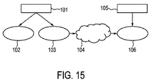
図1は、物体の特性を決定するための特性決定装置1を概略的且つ例示的に示す。特性決定装置1は、この実施例では人20の心臓である物体3の画像を供給する画像供給ユニット2を有している。特性決定装置1は、更に、当該物体の光学特性を示す光学感知データを発生するための光学センサと、該物体の超音波特性を示す超音波感知データを発生するための超音波センサとを含むカテーテル21を有している。該カテーテルは、心臓3の内壁の特性を決定するために人20に上記光学センサ及び超音波センサが導入されるのを可能にする。特性決定装置1は、更に、心臓3の内壁にエネルギを供給するための、本実施例ではRF電極であるエネルギ供給エレメントを有している。該エネルギ供給エレメントも、上記カテーテル21に組み込まれている。このように、カテーテル21は人20に導入することができ、その場合、エネルギを心臓3の内壁に供給することができると共に、該心臓3の内壁の特性を、エネルギが供給される位置で決定することができる。斯かる特性は、エネルギが供給される前、エネルギが供給されている間、及び/又はエネルギが供給された後に決定することができる。該エネルギは、心臓3の内壁の心臓組織を焼灼(ablate)するための焼灼エネルギである。
FIG. 1 schematically and exemplarily shows a characteristic determining
図2及び図3は、カテーテル21の遠端部22を概略的且つ例示的に示している。図2及び3において、焼灼電極4は、電気エネルギを供給するための電気接続部を介してエネルギ源24に接続されたキャップ電極であり、上記エネルギは心臓3の内壁に供給することができる。この実施例において、エネルギ源24、上記電気接続部及び焼灼電極4は、心臓3の内壁にRFエネルギを供給するように構成されている。上記電気接続部は、好ましくは、カテーテル21内に配置されたワイヤとする。該カテーテル21の遠端部22は、局部電気記録を測定するための電極5を更に有している。測定された局部電気記録は、例えば、電気解剖学的マップを発生及び/又は補正するために使用することができ、及び/又は上記局部的電気記録は前記特性決定装置のディスプレイ上に表示され、局部的な電気記録をユーザに表示して、特に、該ユーザがエネルギを該測定された局部的電気記録に依存して供給するのを可能にすることができる。電極5は、電気ワイヤ等の電気接続部を介して電気信号処理ユニット86に接続される。該電気信号処理ユニット86は、電極5から入力された局部電気記録を処理し、該処理された局部電気記録を、例えば、ディスプレイに供給して、該局部電気記録をディスプレイ上に表示する。特に、電気信号処理ユニット86は、好ましくは、電極5により測定された局部電気記録をデジタル化し、該デジタル化された局部電気記録を上記ディスプレイに供給するように構成される。
2 and 3 schematically and exemplarily show the
カテーテル21の遠端部22の先端における焼灼電極4は、好ましくは、該先端の金属部分である。他の例として、該先端は、例えば、上記焼灼電極を形成するために導電性材料で被覆されたポリマから形成することもできる。
The ablation electrode 4 at the distal end of the
前記光学センサは、好ましくは、心臓3の内壁を光により照射するための発光手段と、心臓3の内壁から光を受光するための受光手段とを有し、該光学センサは受光された光に依存して光学感知データを発生するように構成される。この実施例において、上記発光手段及び受光手段は、異なる位置において心臓3の内壁を照射すると共に、心臓3の内壁から光を受光するための幾つかの光ファイバ6を有している。心臓3の内壁を照射するための該幾つかの光ファイバは光源7に接続され、その場合、該光源は1ないし数個のレーザを有し、これら数個の光ファイバ6は光源7からの光を心臓3の内壁まで案内する。心臓3の内壁から光を受光するための上記幾つかの光ファイバは、心臓3の内壁の1ないし数個の光スペクトルを発生するためのスペクトルメータ(分光計)73に接続される。
The optical sensor preferably has light emitting means for irradiating the inner wall of the heart 3 with light, and light receiving means for receiving light from the inner wall of the heart 3, and the optical sensor converts the received light into light. Dependently configured to generate optical sensing data. In this embodiment, the light emitting means and the light receiving means have several
焼灼電極4は、当該カテーテル21の内部で案内される注水液(irrigation fluid)が注水目的で該カテーテル21の遠端部22から流出するのを可能にする幾つかの注水口8及び9を有している。カテーテル21の遠端部22は、第2の種類の注水口9より大きな第1の種類の注水口8を有している。この実施例においては、個別にアドレス指定可能な幾つかの超音波センサ(即ち、超音波トランスジューサ10)が、当該焼灼電極4の内部に物理的に閉じ込められると共に、該焼灼電極4内に各超音波トランスジューサ10が心臓3の内壁を上記大きな注水口8の1つを介して感知することができるように配置されている。
The ablation electrode 4 has
好ましくは、大きな注水口8及び/又は小さな注水口9に、2つの光ファイバが当該注水口にまたがって例えば1mmの距離で配置される。これら2つの光ファイバのうちの一方は当該物体に光を放出するために使用され、他方は該物体から光を受光するために使用されて、下に位置する組織の吸収及び/又は散乱特性に依存する光スペクトルを測定するようにするのが好ましい。しかしながら、他の実施例では、ファイバをカテーテル21の遠端部22上に如何なる他の空間的分布に従って配置することもできる。
Preferably, two optical fibers are arranged in a
一実施例において、大きい方の開口8は、これら大きい方の開口8を介して当該カテーテル21の遠端部22から注水液が流出するのを可能にすることなく、対応する大きい方の開口8を介して超音波トランスジューサ10が心臓3の内壁を感知するのを可能にするためにのみ使用される。カテーテル21の遠端部22は2.4mmなる直径を有することができ、上記大きい方の開口8は0.5mmなる直径を有することができる。光ファイバ6は0.25mmなる直径を有することができ、1つの開口にまたがって配置される1対の光ファイバの間の距離は、1.0〜2.0mmの範囲内、特には1.2〜1.8mmの範囲内とすることができる。
In one embodiment, the
当該特性決定装置1は、更に、ユーザが心臓組織への注水を制御することを可能にするために、注水管を介して前記注水口8、9に接続された注水制御ユニット63を有する。超音波トランスジューサ10が、対応する注水口を介して心臓3の内壁を感知することができるように配設される場合、該超音波トランスジューサと心臓組織との間の接触が、特に当該焼灼電極4内の空間が上記注水管と流体的に接続されている場合、前記注水液により仲介される。超音波トランスジューサが心臓の内壁を感知することができる開口が、注水目的で使用されない場合、該開口は窓により閉じることができる。この場合、当該超音波トランスジューサと心臓組織との間の接触は、上記窓のポリメチルペンテン(polymethylpentene)又はパリレン(parylene)等の音響的に透明な材料により仲介される。
The
画像供給ユニット2は、好ましくは、心臓3の電気解剖学的マップを供給するように構成される。この実施例において、画像供給ユニット2は、電気解剖学的マップが記憶される記憶ユニットである。該電気解剖学的マップは、例えばコンピュータ断層撮影システム、磁気共鳴画像化システム、核画像化システム若しくは超音波画像化システムを使用することにより、又はカテーテル先端の位置のインピーダンス、磁気、電磁気若しくは光学に基づく追跡(トラッキング)により、及び当該心臓の壁上の異なる位置における該心臓の電気特性を測定することにより心臓3の三次元画像を発生させることにより発生することができ、上記の測定された電気特性は心臓の上記三次元画像において対応する位置で視覚化される。
The
例えば、電気解剖学的マップは解剖学的基質の活性化シーケンス(興奮順序)を反映する活性化マップとすることができる。この活性化マップから、伝導パターンを導出することができ、例えば、遅い活性化の区域又はリエントラント波を明らかにする。上記活性化マップからの情報は、エネルギが供給されるべき焼灼目標を識別するために用いることができる。 For example, the electroanatomical map may be an activation map that reflects the activation sequence (excitation order) of the anatomical substrate. From this activation map, a conduction pattern can be derived, e.g. revealing areas of slow activation or reentrant waves. Information from the activation map can be used to identify the ablation target to be supplied with energy.
当該特性決定装置1は、更に、焼灼電極4を位置特定する位置特定ユニット76、74を有している。該位置特定ユニットは、X線源25とX線検出器26とを備えたX線蛍光透視システム76を有している。X線源25はX線ビーム27を放出し、該X線ビームはカテーテル21の遠端部22を含む心臓3を横断する。心臓3を横断したX線ビームはX線検出器26により検出される。該X線検出器26は、検出されたX線ビームに依存する電気信号を発生し、該電気信号はX線投影画像を発生するために蛍光透視制御ユニット28により使用される。該蛍光透視制御ユニット28は、X線源25及びX線検出器26を制御するようにも構成されている。X線源25及びX線検出器26は、患者20の周りで回転可能となるように構成することができ、X線蛍光透視システム76が異なる方向のX線投影画像を発生するのを可能にする。該X線蛍光透視システムは、例えば、コンピュータ断層撮影蛍光透視システム又はC字状アーム蛍光透視システムである。上記X線投影画像は、心臓3内での焼灼電極4の位置を決定するために、位置決定ユニット74へ供給される。供給されたX線投影画像に基づいて心臓3内の焼灼電極4の位置を決定するためには、既知の位置決定方法を用いることができる。例えば、当該焼灼電極を異なるX線投影画像内で認識することができ、このことは、位置決定ユニット74が、焼灼電極4の各投影を生じさせたX線の各経路を決定することを可能にする。位置決定ユニット74は、これら経路の交差から心臓3内の焼灼電極4の位置を決定するように構成することができる。又は、心臓3内の焼灼電極4の三次元画像を上記X線投影画像から、例えば逆投影アルゴリズムを使用することにより発生することができ、その場合、位置決定ユニット74は、心臓3内の焼灼電極4の位置を、該発生された三次元画像において心臓3内の焼灼電極4を認識することにより決定するよう構成することができる。位置決定ユニット74は、当該カテーテルの(特には、焼灼電極4の)向きを決定するようにも構成することができる。
The characteristic determining
他の実施例において、上記位置特定ユニットは、磁気共鳴画像化システム、又は当該カテーテルの遠端部に例えば磁気及び/又はインピーダンスに基づくトラッキングのための位置センサ等の他の手段を有し、心臓3内の(特には、例えば該心臓の電気解剖学的マップ内の)焼灼電極4の位置及びオプションとして向きも決定することができる。他の実施例では、該位置特定ユニットは、例えばファイバ・ブラッグ格子又はレイリー散乱に基づく光学形状感知のためのセンサを有する。 In another embodiment, the localization unit comprises a magnetic resonance imaging system or other means such as a position sensor for tracking based on magnetism and / or impedance at the distal end of the catheter, The position and optionally the orientation of the ablation electrode 4 in 3 (especially in the electroanatomical map of the heart, for example) can also be determined. In other embodiments, the localization unit comprises a sensor for optical shape sensing based on, for example, a fiber Bragg grating or Rayleigh scattering.
当該特性決定装置1は、更に、前記光学感知データ及び超音波感知データに基づいて心臓3の内壁の特性を決定するための特性決定ユニット75を有している。特に、該特性決定ユニット75は物体の特性を前記光学センサにより決定された光スペクトルに依存して決定するように構成される。この実施例では、特性決定ユニット75は心臓3の内壁の特性を上記光スペクトルから決定するように構成されている。該光スペクトルは表面の(特には、表面層の)吸収及び/又は散乱特性を示し、その場合、前記光学センサの光は、心臓3の内壁の表面(特には表面層)を貫通することができ、従って該表面の(特には、該表面層の)散乱及び/又は吸収特性を決定するために使用することができる。特に、該特性決定ユニット75は、心臓3の内壁の散乱及び/又は吸収特性に影響を与えるような、該心臓3の内壁の特性を決定することができる。この実施例において、特性決定ユニット75は、心臓組織が焼灼されたか又は焼灼されていないかを前記光スペクトルに基づいて決定するように構成される。該特性決定ユニット75は、更に、前記光学センサにより感知されて組織の種類又は該組織の組成を決定するように構成することができる。
The characteristic determining
上記特性決定ユニット75はメモリを有し、該メモリには、焼灼された心臓組織に又は焼灼されていない心臓組織に割り当てられる光スペクトルが記憶される。該特性決定ユニット75は、記憶された光スペクトルを、実際に測定された光スペクトルと比較して、該光学的に感知された心臓組織が焼灼されたか否かを決定するように構成される。該特性決定ユニット75が更に組織の種類又は組織の組成を決定するように構成される場合、異なる種類の組織に又は可能性のある異なる組織要素に割り当てられる光スペクトルも前記メモリに記憶され、その場合、該特性決定ユニット75は、対応する組織の種類又は組織の組成を、記憶された光スペクトルを実際に測定された光スペクトルと比較することにより決定するよう構成される。
The
光スペクトルを決定するために、前記光学センサは心臓3の内壁を異なる波長を持つ光で照射することができ、光スペクトルは分光計73を使用することにより発生される。他の例として、当該光学センサは、心臓の内壁から光を受光するための各光ファイバが実質的に1つのみの波長の光を受光するように、該心臓の内壁を時間的に連続して異なる波長で照射するように構成することもできる。この場合、分光計は不要とすることができるが、光検出器は各波長に対して感知的なものとする。このように、心臓の内壁からの光を受光した光ファイバの出力は、検出器信号を発生するフォトダイオードにより検出することができ、該検出器信号は、後に更に説明するアルゴリズムに従って処理することができる。光はカテーテル21の遠端部22から少なくとも1つの光ファイバを介して導出され、波長は例えば500nmから1600nmまで掃引することができる。空間的及び時間的に(即ち、波長依存的に)多重化することにより、光スペクトルは心臓3の内壁の複数の場所で測定することができる。カテーテル21の遠端部22は幾つかの対の光ファイバを有しているので、1つのカテーテル21を使用することにより、幾つかの光スペクトルを、該カテーテルを異なる場所での異なる光スペクトルの測定の間において移動させることなく、心臓3の内壁の異なる場所で決定することができる。特に、異なる場所における光スペクトルを1つのカテーテル21で同時に測定することができる。
In order to determine the light spectrum, the optical sensor can illuminate the inner wall of the heart 3 with light having different wavelengths, and the light spectrum is generated by using a
上記では光スペクトルの測定(拡散反射分光法と考えることができる)を、組織特性を導出するために使用されるものとして説明したが、前記光学センサは組織特性を決定するために前記特性決定ユニットにより使用される光学感知データを発生するための他の光学的測定を実行するように構成することもできる。例えば、他の実施例では、光学センサを、光学感知データを発生するために蛍光測定、複数の光ファイバを使用することによる拡散光学断層撮影、差分経路長分光法又はラマン分光法を実行するように構成することもできる。 In the above, the measurement of the optical spectrum (which can be thought of as diffuse reflectance spectroscopy) has been described as being used to derive the tissue properties, but the optical sensor is used to determine the tissue properties Can be configured to perform other optical measurements to generate optical sensing data used by the. For example, in other embodiments, the optical sensor is configured to perform fluorescence measurements, diffuse optical tomography by using multiple optical fibers, differential path length spectroscopy, or Raman spectroscopy to generate optical sensing data. It can also be configured.
特性決定ユニット75は、ヘモグロビン、酸化されたヘモグロビン、水、脂肪等の異なる組織発色団の散乱係数及び/又は吸収係数等の光学的組織特性を決定するように構成することができる。これらの光学的組織特性は、組織焼灼の間に変化し、焼灼された組織と比較して健康な組織の場合、健康な組織(特には、健康な筋肉組織)は既に焼灼された組織又は脂肪から区別することができるように、非常に相違する。異なる組織発色団の散乱係数及び/又は吸収係数を決定するために、特性決定ユニット75は、測定された光スペクトルにJournal of Biomedical Optics, Vol. 15(3), pages 1-10, May/June 2010のRami Nachabe’他による“Estimation of lipid and water concentrations in scattering media with diffuse optical spectroscopy from 900 to 1600 nm”(参照により本明細書に組み込まれる)に開示されたスペクトル適合手順を適用するよう構成することができる。該特性決定ユニットは、例えばAnalytical Chemistry, vol. 60, no. 11, pages 1193 〜 1202, June 1988のDavid M. Haaland他による“Partial Least-Squares Methods for Spectral Analyses. 1. Relation to Other Quantitative Calibration Methods and the Extraction of Qualitative Information”に開示された主成分分析を利用することにより光スペクトルの差を区別するように構成することもできる。上記主成分分析は、光スペクトルの差を分類することを可能にし、従って組織の間の区別、特には焼灼された組織と焼灼されていない組織との間の区別を可能にする。
The
既述したように、上記特性決定ユニットは、実際に測定された光スペクトルを、焼灼された組織又は焼灼されていない組織に割り当てられた記憶された光スペクトルと比較することにより、焼灼された組織と焼灼されていない組織との間を区別するように構成することもできる。図4は心臓の内壁上の第1位置における焼灼された組織の光スペクトルを概略的且つ例示的に示し、図5は該心臓の内壁上の第2位置(上記第1位置とは異なる)における焼灼されていない組織の光スペクトルを概略的且つ例示的に示し、図6は該心臓の内壁上の第3位置(上記第1位置及び第2位置とは異なる)における焼灼された組織の光スペクトルを概略的且つ例示的に示す。これらの図において、縦軸は受光された光の強度Iを任意の単位で示し、横軸は波長λをナノメートルで示す。これらの図から分かるように、焼灼された組織の光スペクトル(図4及び6)は非常に類似する一方、図5に示される焼灼されていない組織の光スペクトルとは相違する。このように、実際に測定された光スペクトルを、焼灼された組織に又は焼灼されていない組織に割り当てられた記憶された光スペクトルと比較することにより、当該光スペクトルが実際に測定された位置において、当該組織が焼灼されているか又は焼灼されていないかを決定することができる。 As already mentioned, the characterization unit is responsible for comparing the actually measured light spectrum with the stored light spectrum assigned to the ablated tissue or non-cauterized tissue. It can also be configured to distinguish between non-cauterized tissue. FIG. 4 schematically and exemplarily shows the light spectrum of the ablated tissue in a first position on the inner wall of the heart, and FIG. 5 shows a second position on the inner wall of the heart (different from the first position). FIG. 6 schematically and exemplarily shows the light spectrum of the non-cauterized tissue, and FIG. 6 shows the light spectrum of the cauterized tissue at a third position on the inner wall of the heart (different from the first and second positions). Is schematically and exemplarily shown. In these figures, the vertical axis indicates the intensity I of received light in arbitrary units, and the horizontal axis indicates the wavelength λ in nanometers. As can be seen from these figures, the light spectrum of the ablated tissue (FIGS. 4 and 6) is very similar, but is different from the light spectrum of the non-cauterized tissue shown in FIG. Thus, by comparing the actually measured light spectrum with the stored light spectrum assigned to the ablated tissue or to the tissue that has not been ablated, at the location where the light spectrum was actually measured. , It can be determined whether the tissue is cauterized or not.
実際に測定された光スペクトルを、記憶された光スペクトルと比較するために、特性決定ユニット75は、好ましくは、相関又は差分平方和等の類似尺度を用いるように構成される。
In order to compare the actually measured light spectrum with the stored light spectrum, the
特性決定ユニット75は、特にはレーザドプラ流速測定法(LDF)を使用することにより前記光学感知データから心臓組織の潅流の程度を決定するように構成することもできる。決定された潅流の程度は、組織の(特には、心臓組織の)血液潅流の異常を検出するために使用することができ、斯かる異常は例えば心筋梗塞後の散乱された組織(scattered tissue)を区分することにより、焼灼を使用することにより対処することができる。特性決定ユニット75が、心臓組織が焼灼されているか又は焼灼されていないかをLDFを用いることにより決定するように構成される場合、前記光学センサは好ましくは少なくとも3本の光ファイバ(1本は当該物体を照射するためのものであり、2本は該物体から光を受光するためのものである)を有し、当該物体を照射するための光ファイバは、該物体から光を受光するための2本の光ファイバから異なる距離に配置される。他の例として、上記光学センサは当該物体を照射するために種々の波長を使用するように構成することもできる。上記LDFは、例えば焼灼の間における局部的加熱に対する微小循環応答(末梢血流反応)を追跡することにより心臓組織を診断することも可能にする。LDFは、1〜1.5mm厚までの心臓組織の血液潅流の数量化を可能にし、該血液潅流はmm/sでの特定の組織の100g当たりの赤血球の数で数量化することができる。当該特性決定ユニットにより潅流の程度が決定された場合、該特性決定ユニットは、該決定された潅流度を閾処理することにより、当該組織が焼灼されているか又は焼灼されていないかを決定することができる。対応する閾値は校正測定により決定することができ、その場合、感知される組織が焼灼されているか又は焼灼されていないかが既知である際に、潅流の程度が決定される。LDFに関する一層詳細な説明は、例えば、Journal of Biomedical Optics, Vol. 13(1), pages 1 to 12, January/February 2008のIngemar Fredriksson他による論文“"Optical microcirculatory skin model: assessed by Monte Carlo simulations paired with in vivo laser Doppler flowmetry”(参照により本明細書に組み込まれる)に見ることができる。
The
焼灼エネルギは、好ましくは、心臓の内壁にラインに沿って供給されるようにし、その場合、特性決定ユニット75は、好ましくは、焼灼エネルギが該ラインに沿って連続的に供給されたかを光スペクトルに依存して決定するように構成される。好ましくは、前記光学センサは光スペクトルを上記ラインに沿う幾つかの位置において発生し、焼灼エネルギが該ラインに沿って連続的に供給されたかを該発生された光スペクトルに依存して決定するように構成されるようにする。例えば、カテーテル21の遠端部22は上記ラインに沿って連続的に移動され、このラインに沿って光スペクトルを測定することができる。上記特性決定ユニットは、好ましくは、心臓組織が上記ラインに沿う異なる位置において焼灼されたか又は焼灼されなかったかを該ラインに沿う異なる位置において測定された光スペクトルに沿って決定し、このラインに沿って該心臓の内壁が連続的に焼灼されたかを決定するように構成される。該特性決定ユニットが上記ラインにおけるギャップを検出した場合、このギャップはユーザに報告することができ、上記ラインを閉じるために、ユーザが、このギャップにおいて当該心臓の内壁を焼灼するのを可能にする。
Ablation energy is preferably supplied along the line to the inner wall of the heart, in which case the
特性決定ユニット75は、更に、心臓の内壁が焼灼された深さを示す深さ影響値を、前記超音波感知データから決定するように構成される。該深さ影響値は、例えば、損傷部の深さ又は心臓の壁に対する貫壁性の度合いである。焼灼電極4は、損傷部の深さにより定められ、該焼灼電極4により生ぜられる深さ影響値に依存して(特には、損傷部の進展に依存して)制御することができる。このように、局部的損傷部の進展を決定することができ、焼灼電極は該決定された損傷部の進展に基づいて制御することができる。
The
貫壁性の度合いを決定するために、特性決定ユニット75は、焼灼電極4がエネルギを供給する位置における当該心臓の内壁の厚さを超音波信号から決定するよう構成され、その場合、該貫壁性の度合いは損傷部の深さと心臓の内壁の厚さとに基づいて決定される。
In order to determine the degree of transmurality, the
前記超音波感知データは、異なる深さにおける当該心臓の内壁の超音波反射特性を表す超音波信号であり、前記特性決定ユニット75は該超音波信号の不連続性を検出すると共に、損傷部の深さを該不連続性が生じる超音波信号の深さとして決定するように構成される。該超音波信号は、好ましくは、異なる時点における超音波反射特性も表す。即ち、該超音波信号は好ましくはMモード画像であり、これにより、損傷部の深さを異なる時点で、特にはリアルタイムで決定することを可能にする。この構成は、焼灼電極4を損傷部の深さに依存してリアルタイムで、過剰過熱等の過剰治療及び治療不足が防止されるように制御することを可能にする。
The ultrasonic sensing data is an ultrasonic signal representing an ultrasonic reflection characteristic of the inner wall of the heart at different depths, and the
以下では、超音波信号からの損傷部の深さ及び物体の壁厚の決定を例示的に説明する。 Hereinafter, the determination of the depth of the damaged portion and the wall thickness of the object from the ultrasonic signal will be described as an example.
超音波パルスが物体に対して送出された場合、該超音波パルスは異なる深さにおいて反射され、対応する超音波素子(超音波エレメント)、即ち超音波トランスジューサ10によりエコー信号が受信されるようになる。物体内の異なる深さにおける当該超音波パルスの反射により発生される斯かるエコー信号は、エコー系列(echo series)を形成する。或るエコー系列51が図7に概略的且つ例示的に示されている。当該超音波パルスが物体に対して送出された後にエコーが記録される際の音の速度及び時間を考慮することにより、当該エコー系列は、上記物体の超音波反射特性の該物体内の深さに対する依存度に変換することができる。図7では、任意の単位での当該エコー系列の振幅a(超音波反射特性に対応する)が、上記パルスが物体内へと送出された後に対応するエコーが受信された時点に対応する、任意の単位での深さdに依存して示されている。
When an ultrasonic pulse is transmitted to an object, the ultrasonic pulse is reflected at different depths so that an echo signal is received by a corresponding ultrasonic element (ultrasonic element), that is, the
この実施例において、当該物体は心臓であり、上記超音波パルスは該心臓の内壁の組織内へと送出される。図7において、当該エコー系列51の符号52及び53により示される区域は、心臓壁の前側及び後側表面に対応する。区域54は上記超音波パルスにより直接発生されるものである。このように、厳密な意味では、該エコー系列は上記区域54を除いた図7に示されるグラフである。
In this embodiment, the object is the heart and the ultrasound pulse is delivered into the tissue on the inner wall of the heart. In FIG. 7, the areas indicated by
図7に示されるエコー系列51は、当該超音波パルスを放出すると共に当該エコーを受信する超音波素子の位置に対する前側及び後側表面52、53の位置を決定することを可能にする。区域54における最初に測定される振幅は、当該超音波素子の位置を示すものである。該区域54には実質的にゼロの振幅を持つ区域が後続し、その暫くの後、振幅は当該物体における最初の反射を示す、即ち該物体の前側表面を示す区域52で再び増加する。当該心臓の組織内での反射に対応する小さな振幅を持つ区域55が続き、次いで、区域53では該振幅は再び大きく増加し、これにより当該心臓壁の後側表面を示す。このように、エコー系列51は、区域52及び53に基づいて上記前側及び後側表面の位置を決定することを、従って斯かる前側及び後側表面の位置の間の差として局部的な物体の壁厚を決定することを可能にする。間の区域55は、後に更に説明するように、損傷部の深さを決定するために使用される。
The
実質的にゼロの振幅を持つ区域の後の区域52における増加する振幅の位置は、当該物体の前側表面の位置として決定することができる。次いで、当該振幅は区域55において大幅に減少し、該振幅における次の大幅な増加の位置(区域53)は当該心臓壁の後側表面として決定される。言い換えると、区域54における当該超音波素子の励起終了(ring down)の後、“沈黙期間”が続く。この沈黙期間は、上記前側表面に関連する区域52における反射により実質的に終了される。この区域52における反射の後、超音波強度の速く且つ小さな温度変化により示される期間55が生じる。特に、該期間55における信号の包絡線は、指数関数的な強度の低下を有する傾向がある。該期間55の終了時において、再び、上記後側表面に関連する強い反射が区域53で観測される。閾値を予め定めることができ。特に、相対閾値を予め定めることができ、その場合、前記“沈黙期間”の後の反射が対応する所定の閾値を越えたら前側表面が検出され、期間55の終了時に当該信号が対応する閾値を越えたら後側表面が検出される。これら閾値は、既知の前側表面及び後側表面の位置を持つ壁に対する校正測定により予め定めることができる。
The position of increasing amplitude in the
図7に概略図示されたエコー系列51は、或る時点に当該物体内へと送出された超音波パルスにより発生されたものである。これら超音波パルスの幾つかが当該物体に対して異なる時点で送出され、これにより、エコー系列を異なる時点で発生させる。異なる時点における異なる超音波パルスから得られ、従って異なる時点に属する、これらのエコー系列は、動的なエコー系列を形成する。受信された動的エコー系列に依存する超音波信号は、従って、当該物体の異なる深さ及び異なる時点における超音波反射特性を表す。このような超音波信号が、図8に概略的且つ例示的に示されている。
The
図8では、当該超音波信号の異なる振幅が異なる輝度により示されており、一層高い輝度は一層大きな振幅に対応している。振幅は、対応するエコー系列が発生された時点t及び深さdに従って示されている。図8に示された超音波信号は、Mモード画像と見なすことができる画像を形成している。 In FIG. 8, different amplitudes of the ultrasonic signal are indicated by different luminances, with higher luminance corresponding to higher amplitudes. The amplitude is shown according to the time t and the depth d when the corresponding echo sequence is generated. The ultrasonic signal shown in FIG. 8 forms an image that can be regarded as an M-mode image.
焼灼処置を実行することにより、心臓壁に損傷部が生じ、該損傷部の深さは当該心臓壁組織内の損傷部の境界により定められる。 By performing an ablation procedure, a lesion is created in the heart wall, and the depth of the lesion is defined by the boundary of the lesion in the heart wall tissue.
前記特性決定ユニットは、上記超音波信号における不連続部を決定すると共に、損傷部の深さを該超音波信号における上記不連続部が生じる深さとして決定するように構成される。例えば、図8において、第1の楕円部56内には超音波信号の連続的な変化しか存在せず、当該組織に対する焼灼エネルギの供給の間における該心臓壁組織の巨視的組織膨張を示している。第2の楕円部57では、当該超音波信号の変化の不連続部を観察することができ、これは損傷部の深さを示す。このように、図8は第2の楕円部57内に、損傷部の進展、即ち増加する損傷部の深さを示している。観察される不連続部に基づいて、ある時点に対して第2双頭矢印59により例示的に示されるように、損傷部の深さが決定される一方、第1の双頭矢印はある時点に対する心臓壁の厚さを示す。尚、図8に見られるように巨視的組織膨張により焼灼処置を実行している間において時間に伴い心臓壁の厚さも変化することに注意すべきである。
The characteristic determining unit is configured to determine a discontinuity in the ultrasound signal and to determine a depth of a damaged portion as a depth at which the discontinuity in the ultrasound signal occurs. For example, in FIG. 8, there is only a continuous change in the ultrasound signal within the
損傷部の深さを決定するために、前記特性決定ユニットは組織膨張による当該超音波信号の時間分解された移動(シフト)、特には巨視的な移動を推定するように構成することができる。特に、当該超音波信号の連続した変化が検出され、超音波パルスが当該物体内へと送出され、該物体により異なる深さで反射された各時点に対して組織膨張による該超音波信号の移動を決定するために使用される。次いで、該特性決定ユニットは、焼灼の間の組織膨張に起因する上記移動を補正するために移動が補正された超音波信号を計算する。特には、異なる時点に対して、例えば図8に示された振幅値が、上記の決定された移動に対応して垂直に移動され、組織膨張に起因する該移動を補償する。次いで、該特性決定ユニットは好ましくは上記の移動が補償された超音波信号におけるノイズを例えばσ=25のガウスフィルタを用いて抑圧する。一実施例において、上記特性決定ユニットは、分離的な事象が発生するまで、上記の移動が補償された超音波信号における時間に対して一定な深さに対応するラインを追跡するように、即ち図8に示された表示に対応する上記の移動が補償された超音波信号の表示における水平なラインを追跡するように構成される。従って、この分離的事象が発生する前の当該水平ラインの長さは相関統計により決定される。この場合、上記特性決定ユニットは、焼灼された/焼灼されていない区域を、上記の決定された接続された区域(stretches)の長さに基づき、柔軟性のあるままであるカットオフパラメータを用いて割り当てるよう構成される。該カットオフパラメータは、例えば、0.25sである。特には、移動が補償された超音波画像において、水平ライン上の時間的に隣接するピクセルが比較される。水平ラインに沿って損傷部の境界が存在しない場合、該水平ラインに沿うピクセルは概ね同一の輝度を有する傾向があり、緩やかな変化のみが発生し得る。対照的に、損傷部の境界、即ち焼灼損傷部が水平ラインに到達すると、このラインにおけるピクセルの輝度が著しく変化する。この輝度の著しい変化に関連する深さが、損傷部の深さを定める。好ましくは、前記特性決定ユニットは、実質的に同一の輝度を持つピクセル値を含む水平ラインに沿った区域を決定するように構成される。焼灼の最前部が或る水平ラインに到達すると、この水平ラインにおける区域の長さの著しい減少が観測される。上記区域の長さが所定の閾値より小さい場合、前記特性決定ユニットは損傷部の深さを、これら区域の長さが該所定の閾値より小さい位置に関連する深さとして決定する。この所定の閾値は、超音波信号が超音波パルスを既知の損傷部長さを持つ物体中に送出することにより発生されるような校正測定により決定することができる。また、水平ライン上の隣接するピクセルの輝度値が類似しているか否かを、即ち水平ライン上の2つの隣接するピクセル値の強度が同一の区域に属するかを決定するための類似尺度も、この校正により決定することができる。例えば、校正により、ピクセル値の輝度値が類似していると見なされる判断に到るようなピクセル値の強度の最大相対差を示す相対閾値を定義することができる。即ち、2つのピクセル値の強度は、これらピクセル値の相対差が、好ましくは校正により定められる上記最大相対差に等しいか又は該最大相対差より小さい場合に類似であると見なされる。一実施例において、0.25sより大きな、更に好ましくは0.5sより大きな、更に一層好ましくは1sより大きな長さを持つ範囲は、当該水平ラインに対応する深さでは焼灼は未だ発生していないことを示すと見なされる。 In order to determine the depth of the damaged part, the characterization unit can be configured to estimate the time-resolved movement (shift) of the ultrasound signal due to tissue expansion, in particular macroscopic movement. In particular, the movement of the ultrasound signal due to tissue expansion for each point in time when a continuous change in the ultrasound signal is detected, an ultrasound pulse is sent into the object and reflected at different depths by the object Used to determine. The characterization unit then calculates a movement-corrected ultrasound signal to correct the movement due to tissue expansion during ablation. In particular, for different time points, for example, the amplitude values shown in FIG. 8 are moved vertically in response to the determined movement to compensate for the movement due to tissue expansion. The characterization unit then preferably suppresses the noise in the ultrasound signal compensated for the above movement, for example using a Gaussian filter with σ = 25. In one embodiment, the characterization unit tracks a line corresponding to a constant depth with respect to time in the ultrasound signal in which the movement is compensated until a separable event occurs, ie The above movement corresponding to the display shown in FIG. 8 is configured to track a horizontal line in the display of the compensated ultrasound signal. Therefore, the length of the horizontal line before this segregation event occurs is determined by correlation statistics. In this case, the characterization unit uses the cut-off parameters that remain inflexible based on the length of the determined connected stretches for the cauterized / non-cauterized areas. Configured to be assigned. The cut-off parameter is, for example, 0.25 s. In particular, temporally adjacent pixels on a horizontal line are compared in a motion compensated ultrasound image. If there is no damage boundary along the horizontal line, pixels along the horizontal line tend to have approximately the same brightness, and only moderate changes can occur. In contrast, when the border of the lesion, that is, the ablation lesion, reaches the horizontal line, the brightness of the pixels in this line changes significantly. The depth associated with this significant change in brightness determines the depth of the damaged part. Preferably, the characterization unit is configured to determine an area along a horizontal line that includes pixel values having substantially the same brightness. When the forefront of the ablation reaches a certain horizontal line, a significant decrease in the length of the area in this horizontal line is observed. If the lengths of the areas are smaller than a predetermined threshold, the characterization unit determines the depth of the damaged part as the depth associated with a position where the length of these areas is smaller than the predetermined threshold. This predetermined threshold can be determined by calibration measurements such that the ultrasonic signal is generated by sending an ultrasonic pulse into an object having a known lesion length. A similarity measure for determining whether the luminance values of adjacent pixels on a horizontal line are similar, that is, whether the intensity of two adjacent pixel values on the horizontal line belongs to the same area, It can be determined by this calibration. For example, a relative threshold may be defined that indicates the maximum relative difference in intensity of pixel values that leads to a determination that the luminance values of the pixel values are considered similar by calibration. That is, the intensities of two pixel values are considered similar if the relative difference between these pixel values is equal to or less than the maximum relative difference, preferably determined by calibration. In one embodiment, a range having a length greater than 0.25 s, more preferably greater than 0.5 s, and even more preferably greater than 1 s, has not yet been cauterized at a depth corresponding to the horizontal line. It is considered to show that.
他の実施例において、前記特性決定ユニットは、前記の移動が補償された超音波信号をフーリエ変換するように構成され、その場合、ノイズは好ましくは例えばガウスフィルタを用いることにより抑圧されているものとする。深さ寸法は異なる深さ範囲に分割され、その場合において、各深さ範囲に関し、同一の時点により定められる各一連の信号値が、先行する同一時点に属する時間的に先行する一連の信号値と相互相関をとられる。このように、各深さ範囲に対して、複数の相互相関ラインが決定される。深さ寸法の異なる深さ範囲への分割は、例えば図8に示されたMモード画像における垂直方向の分割に対応する。例えば、垂直方向のラインは約1000の深さ範囲に分割することができる。該深さ範囲の数は、予め定めることができるか、又は例えば検査されるべき組織の厚さ又は超音波周波数に依存して自動的に又はユーザにより選択することができる。好ましくは、サブミリメートルの厚さを有する非常に薄い動脈組織に対しては深さ範囲の数は1000より小さいものとする一方、20mmより大きな厚さを有する非常に厚い心室組織に対しては深さ範囲の数は1000より大きいものとする。 In another embodiment, the characterization unit is configured to Fourier transform the ultrasonic signal compensated for the movement, in which case the noise is preferably suppressed, for example by using a Gaussian filter. And The depth dimension is divided into different depth ranges, in which case, for each depth range, each series of signal values defined by the same point in time belongs to a preceding series of signal values belonging to the same point in time. And cross-correlation. Thus, a plurality of cross-correlation lines are determined for each depth range. Division into depth ranges having different depth dimensions corresponds to division in the vertical direction in the M-mode image shown in FIG. 8, for example. For example, a vertical line can be divided into approximately 1000 depth ranges. The number of depth ranges can be predetermined or can be selected automatically or by the user, for example depending on the thickness of the tissue to be examined or the ultrasound frequency. Preferably, the number of depth ranges should be less than 1000 for very thin arterial tissue having a submillimeter thickness, while deep for very thick ventricular tissue having a thickness greater than 20 mm. The number of ranges is assumed to be greater than 1000.
各深さ範囲の相互相関ラインは平均される。この平均は、好ましくは、各深さ範囲の相互相関ラインに対して平均フィルタを適用することにより実行される。該平均フィルタは、例えば、11本のラインのフィルタ幅を有する。しかしながら、該平均フィルタは一層広い又は一層狭いフィルタ幅を有することもできる。更に、この実施例において、前記特性決定ユニットは、異なる深さ範囲の平均化され相互相関ラインに逆フーリエ変換を適用すると共に、逆フーリエ変換された相互相関ラインの深さ範囲内のピークを決定するように構成される。このように、好ましくは、各深さ範囲に対し、且つ、各時点に対して、相互相関ラインのピークが決定される。 The cross-correlation lines for each depth range are averaged. This averaging is preferably performed by applying an averaging filter to the cross-correlation lines at each depth range. The average filter has, for example, a filter width of 11 lines. However, the average filter can also have a wider or narrower filter width. Further, in this embodiment, the characterization unit applies an inverse Fourier transform to the averaged cross-correlation lines in different depth ranges and determines a peak within the depth range of the inverse-correlation cross-correlation lines. Configured to do. Thus, preferably the peak of the cross-correlation line is determined for each depth range and for each time point.
前記特性決定ユニットは、各深さ範囲内の上記ピークの深さ位置を、該ピークを対応する相互相関ラインから切り抜くと共に、該切り抜かれたピークに放物線を当てはめることにより決定するよう構成することができる。当てはめられた放物線の最大値は、対応する時点における対応する深さ範囲内の該ピークの深さ位置を定める。 The characterization unit may be configured to determine the depth position of the peak within each depth range by clipping the peak from the corresponding cross-correlation line and fitting a parabola to the clipped peak. it can. The maximum value of the fitted parabola defines the depth position of the peak within the corresponding depth range at the corresponding time point.
前記特性決定ユニットは、更に、各深さ範囲及び各時点に対して、対応する時点における対応する深さ範囲内のピークの深さ位置からシフト値を決定するように構成することができる。上記ピークは相互相関ラインのピークであるから、各深さ範囲内のピークの深さ位置は、対応する相互相関ラインを決定するために相互相関をとられた当該深さ範囲内の2系列の信号値の間のシフトを示す。上記特性決定ユニットは、各深さ範囲内のピークの深さ位置を上記シフト値として決定するように構成することができるか、又は該特性決定ユニットはシフト値を各深さ範囲内のピークの対応する深さ位置に依存して決定するための更なるステップを実行するように構成することができる。例えば、深さ範囲内のピークの深さ位置とシフト値との間の所定の割り当てを、当該特性決定ユニット内に記憶し、対応する深さ範囲内の対応するピークの決定された深さ位置に依存して決定するために使用することもできる。これらの割り当ては、例えば校正により決定することができる。 The characteristic determination unit may be further configured to determine a shift value for each depth range and each time point from the depth position of the peak within the corresponding depth range at the corresponding time point. Since the peak is the peak of the cross-correlation line, the depth position of the peak within each depth range is the two series of the cross-correlation within the depth range that were cross-correlated to determine the corresponding cross-correlation line. Indicates a shift between signal values. The characterization unit can be configured to determine the depth position of the peak within each depth range as the shift value, or the characterization unit can determine the shift value of the peak within each depth range. It can be configured to perform further steps for determining depending on the corresponding depth position. For example, a predetermined assignment between the depth position of a peak in the depth range and the shift value is stored in the characterization unit, and the determined depth position of the corresponding peak in the corresponding depth range It can also be used to determine depending on These assignments can be determined, for example, by calibration.
前記特性決定ユニットは、損傷部の深さ及び焼灼時点を、異なる深さ範囲に関し異なる時点で決定されたシフト値に依存して決定するように構成することができる。損傷部の深さ及び焼灼時点を決定するために、決定されたシフト値に対して好ましくは閾処理が実行される。シフト値が所定のシフト閾値より大きい場合、対応する深さ範囲及び時点が、各々、当該焼灼処置が生じた損傷部の深さ及び焼灼時点と見なされる。このシフト閾値は、予め定められて当該特性決定ユニットに記憶されるもので、校正測定により決定することができる。 The characterization unit may be configured to determine the depth of the damaged part and the ablation time point depending on the shift values determined at different time points for different depth ranges. A threshold process is preferably performed on the determined shift value to determine the depth of the lesion and the time of ablation. If the shift value is greater than a predetermined shift threshold, the corresponding depth range and time point are considered as the depth of the damaged part and the ablation time point, respectively, where the ablation procedure occurred. This shift threshold is predetermined and stored in the characteristic determination unit, and can be determined by calibration measurement.
好ましくは、前記特性決定ユニットは、前記超音波信号に対し高周波フィルタであるノイズ低減フィルタを適用するように構成される。例えば、該高周波フィルタはヒルベルトフィルタとすることができる。しかしながら、該高周波フィルタは、帯域通過カットオフ周波数を用いるフィルタ又は包絡線検出を用いるフィルタ等の他のフィルタとすることもできる。図8は、ヒルベルトフィルタが適用された超音波信号を示している。 Preferably, the characteristic determination unit is configured to apply a noise reduction filter, which is a high frequency filter, to the ultrasonic signal. For example, the high frequency filter can be a Hilbert filter. However, the high frequency filter may be another filter such as a filter using a band pass cutoff frequency or a filter using envelope detection. FIG. 8 shows an ultrasonic signal to which the Hilbert filter is applied.
図8に示された超音波信号を解釈するために、該グラフは図9〜13に示されるように種々の部分に分割して再プロットすることができる。 To interpret the ultrasound signal shown in FIG. 8, the graph can be divided into various parts and re-plotted as shown in FIGS.
図9では、焼灼処置は適用されておらず、例えばRF周波数焼灼電極4は動作されていない。このように、当該超音波信号は時間の変化に対して一定である。即ち、心臓壁の組織の反射特性は実質的に変化されていない。 In FIG. 9, no ablation treatment is applied, for example, the RF frequency ablation electrode 4 is not activated. Thus, the ultrasonic signal is constant with respect to time. That is, the reflection characteristics of the heart wall tissue are not substantially changed.
焼灼に際して、当該組織のエネルギが供給される部分は温度上昇し、当該領域から発する超音波信号は変化し始める(図10)。該過熱された領域は熱負荷により膨張し、当該組織のうちの未だ過熱されていない部分を、図8〜13における下から上への方向に対応する方向に押し上げることも観察される。図11及び12では、焼灼処置が継続すると、当該超音波信号がどのように変化するが示されている。図13において、当該焼灼処置は停止され(即ち、熱源(焼灼エレメント)がオフされ)、その結果、冷却により収縮が生じると共に、当該心臓組織壁の後側表面に対応する縞の、焼灼前の元の位置に向かって戻るような移動(シフト)が生じる。当該組織のうちの処置されなかった部分で動的な信号変化が観察されない部分は、厚さを維持し、位置がずれるだけである。 During the cauterization, the temperature of the portion to which the tissue energy is supplied rises, and the ultrasonic signal emitted from the region starts to change (FIG. 10). It is also observed that the overheated region expands due to heat load and pushes the portion of the tissue that has not yet been overheated in a direction corresponding to the bottom-to-up direction in FIGS. 11 and 12 show how the ultrasonic signal changes as the cautery treatment continues. In FIG. 13, the ablation procedure is stopped (ie, the heat source (cautery element) is turned off), resulting in contraction due to cooling and the streak corresponding to the posterior surface of the heart tissue wall prior to ablation. A movement (shift) occurs to return toward the original position. The portion of the tissue where no dynamic signal change is observed in the untreated portion maintains thickness and only shifts in position.
図14は、前記特性決定ユニットにより異なる時点で決定された損傷部の深さを示すラインであって、これにより焼灼の進展を示すライン30を概略的且つ例示的に示している。図14は、更に、ライン32及び34により、各々、当該心臓組織壁の前側表面及び後側表面の位置を示すと共にライン33により或る時点の損傷部の深さを示すスライドバー31も図示している。図14では、該スライドバー31は焼灼が停止した時点に関して示されている。図14は、焼灼の進展を視覚化するためにディスプレイ10上で示すことができる。
FIG. 14 schematically and exemplarily shows a
図8〜14において、一定の時点に関する当該超音波信号、即ち、これらの図における縦線に沿う超音波信号は、該超音波信号のAラインと見なすことができる。図8〜14において、該超音波信号は任意の単位での当該心臓組織壁内の深さd及び時間tに従って図示されている。 8 to 14, the ultrasonic signal related to a certain time point, that is, the ultrasonic signal along the vertical line in these drawings can be regarded as the A line of the ultrasonic signal. 8-14, the ultrasound signal is illustrated according to depth d and time t in the heart tissue wall in arbitrary units.
前記超音波素子は一方向における視覚化を可能にする単一プローブとすることができ、又は該超音波素子はフェーズアレイ、揺動プローブ、微細加工超音波トランスジューサ(MUT)アレイ等の二次元及び/又は三次元走査を可能にするプローブとすることもできる。 The ultrasonic element can be a single probe that allows visualization in one direction, or the ultrasonic element can be two-dimensional and phase array, oscillating probe, micromachined ultrasonic transducer (MUT) array, etc. It is also possible to use a probe that enables three-dimensional scanning.
特性決定装置1は、更に、焼灼電極4が心臓3の内壁に接触しているかを前記超音波感知データに基づいて判定する接触判定ユニット15を有している。このことは、エネルギの供給を、焼灼電極4が心臓3の内壁に接触しているか否かに従って制御することを可能にする。特に、エネルギの供給を、焼灼電極4が心臓3の内壁に接触している場合にのみ該心臓3の内壁にエネルギが供給されるように制御することができ、これにより心臓3の内壁に対してエネルギを供給する品質を改善する。
The
例えば、当該物体が焼灼電極4と接触しているかを、前記超音波信号から決定することが可能な当該超音波素子10に対する該物体の表面の位置に基づくと共に、焼灼電極4と当該超音波素子10との間の既知の空間的関係に基づいて検証することができる。この空間的関係は既知である。何故なら、当該超音波素子が焼灼電極4内において何の位置に何の向きで配置されているかは既知であり、又は、一実施例では、焼灼電極の一部が当該超音波素子上に、超音波の一部が当該焼灼電極により反射される(例えば、超音波強度の2〜5パーセントが該焼灼電極の一部により反射され得る)ように、僅かに張り出しているからである。後者の場合、焼灼電極は当該超音波信号内で見えるようになり、該焼灼電極の斯様にして既知となった位置を、決定された当該物体の表面の位置と一緒に、該焼灼電極が該物体と接触しているか否かを決定するために使用することができる。また、当該焼灼エレメントが物体と接触しているかを、例えばAライン又はMモード画像の超音波パターンに依存して決定することも可能である。例えば、当該超音波信号が安定していない場合、当該物体と焼灼電極との間の接触は十分に良好ではない、又は全く接触していないと結論することができる。この場合、当該カテーテルの遠端部は、好ましくは、接触力を増加させるために当該物体に向かって押しやられる。
For example, whether the object is in contact with the ablation electrode 4 is based on the position of the surface of the object relative to the
図2及び3を再び参照すると、超音波トランスジューサ10はカテーテル21の遠端部22内に、これらトランスジューサが物体を異なる感知方向で感知することができるように配置されている。特性決定装置1は、更に、カテーテル21の遠端部22内の幾つかの超音波トランスジューサ10のうちの一つの超音波トランスジューサを、発生された光学感知データ(即ち、前記光スペクトル)に依存して選択する超音波センサ選択ユニット77を有し、前記特性決定ユニット75は、損傷部の深さ及び/又は貫壁性の度合い等の特性を該選択された超音波トランスジューサの超音波感知データに従って決定するように構成される。超音波センサ選択ユニット77は、心臓3の内壁に対する感知方向の向きを前記光学感知データから決定すると共に、該決定された向きに基づいて1つの超音波トランスジューサを選択するように構成される。カテーテル21の遠端部22に対する光ファイバ6の及び上記超音波トランスジューサの位置及び向きは既知であるので、上記超音波センサ選択ユニットは、好ましくは、心臓3の内壁に対するカテーテル21の遠端部22の向きを前記光学感知データ及び上記光ファイバ6とカテーテル21の遠端部22との間の既知の空間的関係に基づいて決定すると共に、1つの超音波トランスジューサを、心臓3の内壁に対するカテーテル21の遠端部22の該決定された向き及び超音波トランスジューサ10とカテーテル21の遠端部22との間の既知の空間的関係に基づいて選択するように構成される。超音波センサ選択ユニット77は、好ましくは、エネルギが供給される又は供給された心臓3の内壁の表面に対して最も垂直な感知方向の超音波トランスジューサを選択するように構成される。選択された超音波トランスジューサの超音波感知データは、好ましくは、例えば損傷部の深さ又は貫壁性の度合いを決定するために使用される。
Referring again to FIGS. 2 and 3, the
光スペクトルを異なる方向で測定することができるように、幾つかの光ファイバがカテーテル21の遠端部22上に分散される。超音波センサ選択ユニット77は、好ましくは、何の光ファイバが当該物体(即ち、心臓3の内壁)に接触しているかを示す光学センサ接触情報を決定すると共に、カテーテル21の遠端部22の(従って、心臓3の内壁に対する超音波トランスジューサの感知方向の)向きを上記光学センサ接触情報及び前記幾つかの光ファイバとカテーテル21の遠端部22との間の空間的関係に依存して決定するように構成される。或る光ファイバの端部が心臓3の内壁と接触していない場合、生理食塩水及び/又は血液等の注水液が、該光ファイバの端部と心臓3の内壁との間に存在する。斯かる存在する注水液及び/又は存在する血液の結果、該存在する注水液及び/又は存在する血液を示すような光スペクトルが生じる。このように、実際に測定される光スペクトルを、超音波センサ選択ユニット77のメモリに記憶することができると共に例えば注水液及び/又は血液に割り当てることが可能な記憶された光スペクトルと比較することにより、当該光ファイバの端部と心臓3の内壁との間に注水液及び/又は血液が存在するかを決定し、これにより該光ファイバの端部が心臓3の内壁と接触しているか否かを決定することができる。カテーテル21の遠端部22に対する光ファイバ6の端部の間の空間的関係は既知であるので、カテーテル21の遠端部22の向きは、この既知の空間的関係に基づくと共に、心臓3の内壁と接触している光ファイバの端部の位置に基づいて決定することができる。
Several optical fibers are distributed on the
従って、光学測定に基づく先端の向きに関する(即ち、カテーテル21の遠端部22の向きに関する)情報を、カテーテル21の遠端部22内の複数の超音波トランスジューサ10により記録される超音波感知データの処理のための入力として使用することができる。これが、以下において図15に示すフローチャートを参照して例示的に説明される。
Accordingly, the ultrasonic sensing data recorded by the plurality of
ステップ101において、光ファイバ6を使用することにより心臓3の内壁を感知することによって、光学感知データ(即ち、光スペクトル)が発生される。ステップ102において、特性決定ユニット75は、感知された組織が焼灼された組織であるか又は焼灼されていない組織であるか等の組織表面特性を決定する。更に、ステップ103において、超音波センサ選択ユニット77は、カテーテル21の遠端部22の向きを決定すると共に、ステップ104において、心臓3の内壁に最も垂直な感知方向を持つ超音波トランスジューサを、ステップ103で決定された先端の向き及び超音波トランスジューサ10の感知方向とカテーテル21の遠端部22との間の既知の空間的関係に従って選択する。代わりに、又はステップ104において更に、カテーテル21の遠端部22の上記の決定された向きをユーザに対して示すことができ、これによりユーザがカテーテル21の遠端部22の向きを修正することを可能にする。この場合、この修正の後に、ステップ101、103及び104が再度実行される。他の代替例では、ステップ103で決定されたカテーテル21の遠端部22の向きを、超音波トランスジューサの感知方向が心臓3の内壁に対して可能な限り垂直となるように該カテーテル21の遠端部22の向きを自動的に修正するために使用することもできる。好ましくはステップ101と同時に実行されるステップ105において、超音波トランスジューサ10により超音波感知データが発生される。ステップ106において、前記の選択された超音波トランスジューサの超音波感知データ(即ち、超音波信号)は、深さ影響値を決定するために、特には損傷部の深さ及び/又は貫壁性の度合いを決定するために使用される。
In
図2及び3を再び参照すると、前記光ファイバは、心臓3の内壁を種々の方向で照射するように、特には該内壁を正面方向で及び横目方向でも照射するように構成されている。光ファイバを曲げる能力は限られているので、当該物体を横目方向で照射するために、焼灼電極4の材料内にミラーが形成され、各光ファイバからの光を各側方に向かって反射するようにする。この目的のために、図16に概略的且つ例示的に示されるように、各光ファイバに斜めの遠端を加工形成し、該斜めの遠端の表面を金属層によりコーティングすることにより、光を例えば光ファイバから或る角度で導出することができる。 Referring again to FIGS. 2 and 3, the optical fiber is configured to illuminate the inner wall of the heart 3 in various directions, particularly to illuminate the inner wall in the frontal and lateral directions. Since the ability to bend the optical fiber is limited, in order to irradiate the object in the transverse direction, a mirror is formed in the material of the ablation electrode 4, and the light from each optical fiber is reflected toward each side. Like that. For this purpose, as shown schematically and exemplarily in FIG. 16, each optical fiber is processed with a diagonal far end, and the surface of the oblique far end is coated with a metal layer to produce a light beam. Can be derived from an optical fiber at an angle, for example.
図16において、光ファイバ6はコア91とクラッド(cladding)92とを有している。更に、該光ファイバ6の斜めの端面上にはミラー93を形成するために金属コーティングが設けられている。該金属コーティングは、例えば約5nmの例えばクロム接着促進層上の、例えば銀の約100nmの層とすることができる。当該光は、光経路90に沿って、ミラー93により横目方向に反射されるように案内される。
In FIG. 16, the
特性決定装置1は、更に、カテーテル21(特には、該カテーテル21の遠端部22)が当該物体内の所望の位置へナビゲート(誘導)されるのを可能にするためのナビゲーションユニット29を有している。該ナビゲーションユニット29は、ユーザがカテーテル21を上記遠端部22の決定された位置及び好ましくは向きに従って完全に手により又は半自動でナビゲートすることを可能にするように構成することができる。カテーテル21は内蔵型の案内手段(図1には示されていない)を有し、該案内手段は上記ナビゲーションユニット29により制御することができる。カテーテル21は、例えば遠端部22を当該物体内の所望の位置へ案内するために操縦ワイヤを使用することにより操縦し及びナビゲートすることができる。
The
特性決定装置1は、更に、当該物体の光学感知データ、超音波感知データ及び決定された特性の少なくとも1つを表示するためのディスプレイ80を有する。心臓3の内壁に対して該内壁上のエネルギ供給位置にエネルギが供給されるが、その場合、前記光学センサは該エネルギ供給位置における心臓組織の光学特性を示す光学感知データを発生するように(即ち、該エネルギ供給位置における少なくとも1つの光スペクトルを発生するように)構成され、前記超音波センサは該エネルギ供給位置における超音波感知データを発生するように構成され、前記特性決定ユニット75は当該心臓組織が該エネルギ供給位置において焼灼されているか又は焼灼されていないかを上記光学感知データに基づいて決定すると共に該エネルギ供給位置における損傷部の深さ及び特に貫壁性の度合いを上記超音波感知データに基づいて決定するように構成される。特性決定装置1は、更に、各々が対応するエネルギ供給位置に対して測定及び決定された光学感知データ、超音波感知データ及び決定された特性を記憶するための記憶ユニット78を有する。画像供給ユニット2は、当該心臓の画像(例えば、該心臓の電気解剖学的マップ)を供給するように構成され、その場合、前記ディスプレイ80は該画像上に上記エネルギ供給位置を表示するように構成される。特性決定装置1は、更に、ユーザが表示されたエネルギ供給位置を選択することを可能にするためのユーザインターフェース79を有し、その場合、前記ディスプレイ80は表示されたエネルギ供給位置がユーザにより選択された場合に光学感知データ、超音波感知データ及び決定された特性の少なくとも1つを表示するように構成される。この構成は、ユーザが、選択されたエネルギ供給位置に対応する、光学感知データ、超音波感知データ、及び/又は当該物体の損傷部深さ及び/又は貫壁性の度合い等の決定された特性を精査することを可能にする。また、対応するエネルギ供給位置が選択された場合、カテーテル21の遠端部22の決定された向きを、記憶ユニット78に記憶し、表示することもできる。
The characteristic determining
好ましい作業の流れにおいて、前記光スペクトルはエネルギが供給される前に(即ち、焼灼が始まる前に)及び焼灼の終了時に測定される。カテーテル21の遠端部22の向きは、焼灼の間に決定し、記憶ユニット78に記憶することができる。また、前記超音波感知データは、焼灼の間に測定し、記憶ユニット78に記憶することができる。記憶された情報は、焼灼されたスポットを表すポイント・タグにリンクされ(即ち、エネルギ供給位置を表すディスプレイ80上のタグにリンクされ)、該タグは例えば電気解剖学的マップ上に又はフィリップス社のEPナビゲータ上に表示される。また、各エネルギ供給位置における心臓3の内壁の他の決定された特性も、記憶し、対応する表示タグにリンクすることができる。好ましくは、各エネルギ供給位置において心臓組織が焼灼されたか又は焼灼されなかったかも記憶され、この情報は、焼灼エネルギをラインに沿って供給することにより発生されると共に閉じられなければならない損傷部ラインにおけるタグを識別するために使用することができる。
In a preferred workflow, the light spectrum is measured before energy is applied (ie, before ablation begins) and at the end of ablation. The orientation of the
一種の指紋として働く焼灼されたスポットのスペクトルデータの記憶は、1cmまでである電気解剖学的マップの不正確さの場合、ラインに沿う連続的な焼灼のための一層正確な基準点又は開始点を見付けるために使用することができる。加えて、カテーテル21の遠端部22は、記憶された情報に基づいて、例えばやり直し手順により前の焼灼スポットに移動して戻すことができる。
Spectral data storage of ablated spots that act as a kind of fingerprint is more accurate reference point or starting point for continuous ablation along the line in the case of electroanatomical map inaccuracies up to 1 cm Can be used to find out. In addition, the
図17は、ディスプレイ10を概略的且つ例示的に更に詳細に示す。ディスプレイ10は、心臓及び幾つかのカテーテル720の表示690が示される第1領域600を有することができる。更に、幾つかのエネルギ供給位置がマーカ700を用いることにより示され、この場合、マーカ710はユーザにより選択されている。ディスプレイ10の第2領域610には、エネルギ供給設定値(特には、供給されるパワーの出力及び期間等の焼灼設定値)を示すことができる。ディスプレイ10の第3領域620には、選択されたエネルギ供給位置710において当該心臓組織が焼灼される前に測定された第1光スペクトル630を示すことができると共に、当該焼灼処置が実行された後に該選択されたエネルギ供給位置710において測定された第2光スペクトル640を示すことができる。ディスプレイ10の第4領域650には、選択されたエネルギ供給位置710において測定されたMモード画像730が示される。該Mモード画像730には、当該心臓壁の前壁660及び後壁670並びに損傷部深さを示す損傷部ライン680が示される。該第4領域650には、例えば貫壁性の度合いを記述するテキストを提示することにより、貫壁性の度合いを示すことができる。
FIG. 17 schematically and exemplarily shows the
ディスプレイ10の第1領域600には、X線蛍光透視システム76により発生される蛍光透視画像及び/又は電気解剖学的マップを示すことができる。
The
特性決定装置1は、更に、心臓3の内壁にエネルギが供給されるべきエネルギ供給位置を含むエネルギ供給計画を供給するためのエネルギ供給計画供給ユニット84を有する。特に、該エネルギ供給計画は、当該ラインに沿って組織が連続的に焼灼されるべき閉じたラインに沿うエネルギ供給位置を定める。特性決定装置1は、更に、該特性決定装置を図18に示されるフローチャートを参照して以下に例示的に説明する特性決定方法に従って制御する制御ユニット85を有している。ステップ201において、心臓3の内壁にエネルギが供給されるべきエネルギ供給位置を含むエネルギ供給計画が、エネルギ供給計画供給ユニット84により供給される。ステップ202において、前記エネルギ供給エレメント(即ち、焼灼電極4)、前記光学センサの光ファイバ6及び超音波トランスジューサ10は、移動ユニットとも見なされるナビゲーションユニット29により、上記エネルギ供給計画のエネルギ供給位置(特に、第1エネルギ供給位置)へ移動される。焼灼電極4、光ファイバ6及び超音波トランスジューサ10は、上記エネルギ供給位置へ、カテーテル21の遠端部22を該エネルギ供給位置へ移動させることにより移動される。このように、単一のエレメント(即ち、カテーテル21の遠端部22)しか、該エネルギ供給位置へ移動させる必要がない。ステップ203において、超音波感知データが上記エネルギ供給位置において上記超音波トランスジューサ10の少なくとも1つにより発生され、焼灼電極4が該エネルギ供給位置において心臓3の内壁に接触しているかが前記接触判定ユニット15により上記超音波感知データに基づいて判定される。焼灼電極4が心臓3の内壁に接触していない場合、ステップ204において、該焼灼電極の位置がナビゲーションユニット29により修正される(特には、焼灼電極4が心臓3の内壁に向かって更に移動される)。この焼灼電極4の心臓3の内壁に向かう移動の後、超音波感知データが再び発生され、該焼灼電極4が心臓3の内壁に接触しているかが再び判定される。ステップ203及び204は、焼灼電極4が心臓3の内壁に接触するまで繰り返される。
The
次いで、ステップ205において、前記光学センサにより上記エネルギ供給位置において光学感知データが発生され、前記特性決定ユニット75は、該発生された光学感知データに従って、心臓3の内壁が該エネルギ供給位置においてエネルギにより既に影響を受けたかを判定する。心臓3の内壁が該エネルギ供給位置においてエネルギにより既に影響を受けている場合、当該方法はステップ202で継続し、焼灼電極4、光ファイバ6及び超音波トランスジューサ10を当該エネルギ供給計画の次のエネルギ供給位置へ移動させる。心臓3の内壁が該エネルギ供給位置においてエネルギにより影響を受けていない場合(即ち、心臓3の内壁が該エネルギ供給位置において未だ焼灼されていない場合)、ステップ206において焼灼電極4により該エネルギ供給位置において心臓3の内壁に焼灼エネルギが供給される。ステップ207において、該エネルギ供給位置において前記超音波トランスジューサ10の少なくとも1つにより超音波感知データが発生される。好ましくは、当該心臓3の内壁に対するカテーテル21の遠端部22の向きを決定するために、ステップ205で発生された光学感知データが使用されるものとし、その場合、決定された向きは心臓3の内壁に対して最も垂直な感知方向を持つ1つの超音波トランスジューサを選択するために使用される。更に、ステップ207において、特性決定ユニット75は当該エネルギ供給位置において心臓3の内壁がエネルギにより所定の程度まで影響を受けたかを(特には、心臓3の内壁が貫壁的であるかを)上記超音波感知データにより判定する。ここで、ステップ206及び207は、心臓3の内壁が当該エネルギ供給位置においてエネルギにより前記所定の程度に影響を受けるまで繰り返される。ステップ208において、エネルギが当該エネルギ供給計画の全てのエネルギ供給位置に供給されたかが判定され、エネルギが当該エネルギ供給計画の全てのエネルギ供給位置には供給されていない場合、当該方法はステップ202で継続し、カテーテル21の遠端部22を当該エネルギ供給計画の次のエネルギ供給位置へ移動させる。エネルギが当該エネルギ供給計画により定められた全てのエネルギ供給位置に供給された場合、当該方法はステップ209で終了する。
Next, in
図18を参照して上述した特性決定方法によれば、当該組織表面に関する光学情報が、焼灼のための次の目標スポットへ進むために、即ち当該エネルギ供給計画の次のエネルギ供給位置へ進むために用いられている。代わりに又は加えて、カテーテル21の遠端部22は、可能性のある間隙を走査するために、当該エネルギ供給計画により定められたエネルギ供給位置のラインに沿って移動させることもできる。前記制御ユニットは、カテーテル21の遠端部22が例えば当該心臓の解剖学的マップ(特には、電気解剖学的マップ、X線画像等)を用いることにより各エネルギ供給位置に先ず粗く案内されるように構成することができる一方、カテーテル21の遠端部22における前記光学センサにより測定された光学感知データを、上記遠端部22の(特には、焼灼電極4の)位置決めの微調整のために使用することができる。
According to the characterization method described above with reference to FIG. 18, the optical information relating to the tissue surface proceeds to the next target spot for ablation, i.e. to the next energy supply position of the energy supply plan. It is used for. Alternatively or additionally, the
上述した実施例では、損傷部深さ及び貫壁性の程度等の深さ影響値は、Mモード画像における水平線の中断に基づいて決定されているが、前記特性決定ユニットは深さ影響値を、心臓組織内の血液による超音波パルスの散乱を示す少なくとも1つの散乱値に依存して決定するように構成することもでき、その場合、該特性決定ユニットは該少なくとも1つの散乱値を前記超音波信号により決定するように構成される。 In the above-described embodiment, the depth influence values such as the damaged portion depth and the degree of transmurality are determined based on the interruption of the horizontal line in the M-mode image. , And may be configured to determine in dependence on at least one scatter value indicative of the scatter of the ultrasound pulse by blood in the heart tissue, in which case the characterization unit determines the at least one scatter value as the super value. It is configured to be determined by a sound wave signal.
図19は、Mモード画像である超音波信号300を概略的且つ例示的に示している。該Mモード画像は、当該超音波信号の超音波強度を、当該組織内の異なる深さdに従い、異なる時間tに従って示している。Aにより示される第1期間においては当該組織は血液により潅流されており、Bにより示される第2期間では該組織は血液により潅流されていない。血液潅流を伴う組織は焼灼されていない組織に対応する一方、血液潅流のない組織は焼灼された組織に対応する。このMモード画像は、重なり合わず、且つ、該Mモード画像の全深さ範囲に沿って延びるサンプル窓(サンプルウインドウ)301によりサンプリングされる。前記特性決定ユニットは、上記サンプル窓301の各々に関する幾つかの散乱値を、対応するサンプル窓301内の超音波強度のヒストグラムに従って決定するように構成される。特に、該特性決定ユニットは上記散乱値を一次ヒストグラム及び二次ヒストグラムの少なくとも一方に基づいて決定するように構成される。しかしながら、より高次の統計法を上記散乱値を決定するために使用することもでき、例えば、ガボールフィルタ処理法を前記少なくとも1つの散乱値を決定するために使用することができる。
FIG. 19 schematically and exemplarily shows an
上記特性決定ユニットは、下記の値のうちの幾つかを、対応するサンプル窓301の散乱値として決定するように構成することができる。即ち、一次ヒストグラムの一次平均m1、該一次ヒストグラムの一次分散m2、該一次ヒストグラムの一次エントロピm3、二次ヒストグラムの二次エントロピn1、該二次ヒストグラムの二次エネルギn2、該二次ヒストグラムの二次均質度(同質性)n3、該二次ヒストグラムの二次コントラストn4、該二次ヒストグラムの二次クラスタ傾向n5、該二次ヒストグラムの二次形状n6、該二次ヒストグラムの二次相関n7並びに該二次ヒストグラムの二次相関導関数n8及びn9である。
The characterization unit may be configured to determine some of the following values as the
一次ヒストグラムは標準ヒストグラムであり、異なる超音波強度に対して(即ち、異なる超音波強度のビンに対して)、強度Iを持つ(即ち、対応する強度ビン内に位置する)ピクセルの数P(I)が決定される。この一次ヒストグラムの一次平均m1は、下記の式により定義することができる。

一次分散m2及び一次エントロピm3は、下記の式により定義することができる。
式(1)〜(3)においては、異なる超音波強度Iに対して和が実行される。 In the equations (1) to (3), the sum is executed for different ultrasonic intensities I.
二次の値は、好ましくは、例えばSystems, Man and Cybernetics, IEEE Transactions on Volume: 3, Issue: 6, Digital Object Identifier: 10.1109/TSMC.1973.4309314, Publication Year: 1973, Page(s): 610〜621のHaralick, Robert M; Shanmugam, K; Dinstein, Its'Hakによる論文“Textural Features for Image Classification”に記載されている、所謂、同時生起マトリクスに基づくものとする。斯かる二次値は、Mモード画像における超音波強度の相対位置も考慮すると共に、二次ヒストグラムに基づくもので、下記の式により定義することができ、
ここで、変数i及びjは超音波強度を示す。上記所与の距離は、例えば校正測定により事前に定められ、該校正測定においては、種々の所定距離が、前記二次ヒストグラムに依存して決定された特性が当該物体の既知の特性に可能な限り良好に合致するまで試行される。好ましくは、上記所与の距離は1ピクセルとする。即ち、所与の距離のピクセル対は、好ましくは、直に隣接するピクセルとする。
The secondary value is preferably, for example, Systems, Man and Cybernetics, IEEE Transactions on Volume: 3, Issue: 6, Digital Object Identifier: 10.1109 / TSMC.1973.4309314, Publication Year: 1973, Page (s): 610-621. Based on the so-called co-occurrence matrix described in the article “Textural Features for Image Classification” by Haralick, Robert M; Shanmugam, K; Dinstein, Its'Hak. Such a secondary value is based on the secondary histogram, taking into account the relative position of the ultrasound intensity in the M-mode image, and can be defined by the following equation:
Here, the variables i and j indicate the ultrasonic intensity. The given distance is predetermined by, for example, a calibration measurement, in which various predetermined distances can have characteristics determined in dependence on the secondary histogram as known characteristics of the object. Try until as good a match as possible. Preferably, the given distance is 1 pixel. That is, a pixel pair at a given distance is preferably the immediately adjacent pixel.
前記二次エントロピn1、二次エネルギn2、二次均質度n3、二次コントラストn4、二次クラスタ傾向n5、二次クラスタ形状n6、二次相関n7及び二次相関導関数n8、n9は下記の式により定義することができる。
そうでないと特記しない限り、式(5)〜(13)において、和は超音波強度i及びjに対して行われる。式(5)、(12)及び(13)で使用される対数は、他の底を有することもできる。 Unless otherwise specified, in equations (5)-(13), the sum is performed on the ultrasonic intensities i and j. The logarithms used in equations (5), (12), and (13) can have other bases.
二次散乱値は、Mモード画像の、コントラストのみの代わりに該Mモード画像のピクセルの空間的配置に関係したパターン特性を示す値を提供する。これらの二次統計値は、パターンのランダムさ、規則性及び向きの特性を表す。 The secondary scatter value provides a value that indicates the pattern characteristics of an M-mode image related to the spatial arrangement of pixels of the M-mode image instead of only contrast. These secondary statistics represent the randomness, regularity and orientation characteristics of the pattern.
前記特性決定ユニットは、必ずしも、上述した一次値及び二次値の全てを決定する必要はないことに注意すべきである。好ましくは、該特性決定ユニットは、当該物体の所望の特性の決定を可能にするような種類の散乱値のみを決定するように構成される。当該物体の所望の特性を決定するために使用することができるような種類の散乱値は、校正測定により決定することができ、その場合、当該物体の特性が既知である際に、幾つかの種類の散乱値が決定される。一実施例において、校正測定は、前記散乱値m1〜m3及びn3〜n9を当該組織が焼灼されているか又は焼灼されていないかを判定するために使用することができることを明らかにした。これらの散乱値が、図20〜29に概略的且つ例示的に示されている。これらの図において、各散乱値は、秒での時間に従って任意の単位で示されている。これらの図の全てにおいて、焼灼されていない組織から焼灼された組織への移行は、約60秒〜80秒の間に見られる。 It should be noted that the characterization unit does not necessarily have to determine all the primary and secondary values mentioned above. Preferably, the characterization unit is configured to determine only those types of scatter values that allow the desired properties of the object to be determined. The kind of scatter values that can be used to determine the desired properties of the object can be determined by calibration measurements, in which case several properties are known when the properties of the object are known. The type of scatter value is determined. In one embodiment, calibration measurements clearly show that the scatter values m 1 -m 3 and n 3 -n 9 can be used to determine whether the tissue is cauterized or not cauterized. did. These scattering values are shown schematically and exemplarily in FIGS. In these figures, each scatter value is shown in arbitrary units according to time in seconds. In all of these figures, the transition from non-cauterized tissue to cauterized tissue is seen between about 60-80 seconds.
前記特性決定ユニットは、更に、1つのサンプル窓に関する少なくとも1つの散乱値を、ヒストグラムによるのではなく、当該サンプル窓内の超音波強度の和によって決定するように構成することができる。例えば、この少なくとも1つの散乱値は、対応するサンプル窓内の全ての超音波強度の和とすることができる。該少なくとも1つの散乱値は、下記の式により定めることもでき、
ここで、Itは時点tにおける当該Mモード画像のピクセルの超音波強度を示し、It-pは時点t−pにおける当該Mモード画像のピクセルの超音波強度を示し、pは2つの連続する心拍の間の時間を示す。式(14)において、和は、Itに対応するピクセルが当該サンプル窓内に位置するような全ての対ItIt-pに対して実行される。2つの連続する心拍の間の時間は心電計により決定することができ、該心電計は図1に符号302を付したボックスにより概略的且つ例示的に示されている。他の実施例では、前記特性決定装置は心電計302を有さなくても良く、2つの連続する心拍の間の時間は、例えば、当該Mモード画像から決定することができる。
The characterization unit may be further configured to determine at least one scatter value for a sample window by a sum of ultrasonic intensities within the sample window rather than by a histogram. For example, the at least one scatter value can be the sum of all ultrasonic intensities in the corresponding sample window. The at least one scattering value can also be determined by the following equation:
Here, I t represents the ultrasound intensities of the M-mode image pixel at time t, I tp represents the ultrasound intensities of the M-mode image pixel at the time tp, p is two consecutive heartbeat Indicates the time between. In the formula (14), the sum is performed for all pairs I t I tp as pixels corresponding to the I t is located on the sample within the window. The time between two consecutive heart beats can be determined by an electrocardiograph, which is schematically and exemplarily shown by the box labeled 302 in FIG. In other embodiments, the characterization device may not have an
前記特性決定ユニットは、上記散乱値に基づいて当該物体の特性を決定するように構成することができる。この実施例において、該特性決定ユニットは、上記散乱値に基づいて当該組織の一部が焼灼された組織であるか又は焼灼されていない組織であるかを判断するように構成される。焼灼により当該組織の潅流は変化され得、その場合、該潅流の変化は、超音波パルスの散乱を、従って上記散乱値を変化させる。従って、該散乱値を、当該組織が焼灼されているか又は焼灼されていないかを判断するために使用することができる。 The characteristic determining unit may be configured to determine the characteristic of the object based on the scattering value. In this embodiment, the characterization unit is configured to determine whether a portion of the tissue is cauterized or non-cauterized based on the scattering value. By ablation, the perfusion of the tissue can be changed, in which case the change in perfusion changes the scattering of the ultrasonic pulse and thus the scatter value. Accordingly, the scattering value can be used to determine whether the tissue is cauterized or not.
この実施例において、前記特性決定ユニットは、サンプル窓の散乱値の各々に関して当該組織が焼灼されているか又は当該組織が焼灼されていないかの票決を決定するよう構成される。これら値の各々に関して、上記票決は当該値を所定の閾値と比較することにより実行される。即ち、上記値の各々に関して、二進閾処理が実行されて、各値に対する票決を決定する。前記特性決定ユニットは、最終結果を(即ち、当該サンプル窓に対応する組織が焼灼されているか又は焼灼されていないかを)上記票決の多数決に基づいて判定するように構成される。このことは、或るサンプル窓に関して焼灼されていない側よりも焼灼されている側に一層多くの票決が決定された場合、上記最終結果は、当該サンプル窓に対応する組織は焼灼されているというものであり、逆の場合も同様である。上記所定の閾値は、例えば校正測定により決定することができる。 In this embodiment, the characterization unit is configured to determine whether the tissue is ablated or not ablated for each of the sample window scatter values. For each of these values, the voting is performed by comparing the value with a predetermined threshold. That is, for each of the above values, a binary threshold process is executed to determine a vote for each value. The characterization unit is configured to determine a final result (ie, whether the tissue corresponding to the sample window has been cauterized or not cauterized) based on the voting majority. This means that if more votes are determined on the side that is cauterized than the side that is not cauterized for a sample window, the final result is that the tissue corresponding to that sample window is cauterized. The same applies to the reverse case. The predetermined threshold can be determined by calibration measurement, for example.
前記特性決定ユニットは、前記幾つかの散乱値を多次元特徴ベクトルへと組み合わせるように構成することもできる。即ち、各サンプル窓に関して、多次元特徴ベクトルを定めることができ、その場合、該多次元特徴ベクトルは所定の閾ベクトルと比較されて、当該サンプル窓が焼灼された組織に対応するか又は焼灼されていない組織に対応するかを判定することができる。また、この所定の閾ベクトルも、例えば校正測定により決定することができる。 The characterization unit may also be configured to combine the number of scatter values into a multidimensional feature vector. That is, for each sample window, a multidimensional feature vector can be defined, in which case the multidimensional feature vector is compared to a predetermined threshold vector and the sample window corresponds to the ablated tissue or is ablated. It can be determined whether it corresponds to the organization that is not. The predetermined threshold vector can also be determined by calibration measurement, for example.
前記特性決定ユニットは、前記サンプル窓にクラスタ分析を適用すると共に、サンプル窓の斯かるクラスタに特性を割り当てるように構成することもでき、その場合、サンプル窓は前記多次元特徴ベクトルに依存してクラスタ処理される。例えば、クラスタ分析の結果、サンプル窓の2つのクラスタが得られ、これらクラスタの一方に“焼灼された組織”なる特性が割り当てられ、これらクラスタの他方に“焼灼されていない組織”なる特性が割り当てられる。クラスタが焼灼された組織を表すか又は焼灼されていない組織を表すかは、閾値との比較により決定することができ、その場合、例えばクラスタの前記多次元特徴ベクトルは平均されて、平均ベクトルを発生することができ、該クラスタの平均ベクトルを、校正測定により決定することが可能な閾ベクトルと比較することができる。このように、当該物体の特性のサンプル窓に対する割り当てを、閾処理により実行することができる。前記クラスタ分析が、先ず、焼灼が開始される前に適用されて、焼灼されていない組織を表す第1群のクラスタを得ることもできる。次いで、該クラスタ分析を、当該焼灼処置が実行されている間に連続的に適用することができる。当該クラスタ分析の結果、上記第1群のクラスタに属さない新たなクラスタが得られたら、これらの新たなクラスタに“焼灼された組織”なる特性を割り当てることができる。 The characterization unit may be configured to apply cluster analysis to the sample window and assign characteristics to such cluster of sample windows, where the sample window depends on the multidimensional feature vector. Clustered. For example, the cluster analysis results in two clusters of sample windows, one of which is assigned the characteristic “cauterized tissue” and the other is assigned the characteristic “non-cauterized tissue”. It is done. Whether a cluster represents ablated tissue or non-cauterized tissue can be determined by comparison with a threshold, in which case, for example, the multidimensional feature vectors of the cluster are averaged to obtain an average vector. The average vector of the cluster can be compared to a threshold vector that can be determined by calibration measurements. In this way, the assignment of the object characteristics to the sample window can be performed by threshold processing. The cluster analysis can first be applied before ablation is initiated to obtain a first group of clusters representing unablated tissue. The cluster analysis can then be applied continuously while the ablation procedure is being performed. As a result of the cluster analysis, if new clusters that do not belong to the first group of clusters are obtained, the characteristic of “cauterized tissue” can be assigned to these new clusters.
一実施例において、前記特性決定ユニットは、当該組織の何の部分が焼灼され、該組織の何の部分が焼灼されていないかを判定するために、下記のクラスタ分析技術を適用するように構成される。該クラスタ分析技術を図30〜34を参照して説明するが、これらの図において、図30〜32における上側の部分はMモード画像を示す一方、下側の部分は該クラスタ分析技術の結果を示し、図33及び34は該クラスタ分析技術の幾つかのステップを説明するフローチャートを示す。 In one embodiment, the characterization unit is configured to apply the following cluster analysis technique to determine what part of the tissue is ablated and what part of the tissue is not ablated: Is done. The cluster analysis technique will be described with reference to FIGS. 30 to 34. In these figures, the upper part in FIGS. 30 to 32 shows an M-mode image, while the lower part shows the result of the cluster analysis technique. 33 and 34 show a flowchart illustrating some steps of the cluster analysis technique.
前記特性決定ユニットは、幾つかのサンプル窓331に関して散乱値を決定する。サンプル窓331は、全Mモード画像をサンプリングし、重なり合っている。サンプル窓331の重なり合いは、最終的なクラスタ処理結果の分解能を増加させる。これらサンプル窓は、或る深さ範囲及び或る時間範囲に対応する。サンプル窓331は同じ幅及び同じ長さを有することができるか、又は、これらサンプル窓の幅及び長さは相違し得る。更に、当該Mモード画像は、異なる寸法及び/又は異なる形状を持つ異なるサンプル窓によりサンプリングすることもできる。好ましくは、窓の幅は少なくとも1心拍サイクルをカバーするものとし、その場合、各サンプル窓は心拍に位置合わせすることができる。例えば、各サンプル窓は、対応する収縮サイクルに対して同一の時間のズレで開始することができる。一実施例において、サンプル窓の深さ方向の大きさは、約0.2mmである。
The characterization unit determines scatter values for
第1クラスタ分析技術は焼灼が開始される前に実行され、対応するMモード画像が図30の上側部分に示されている。この第1クラスタ分析技術を、図33に示すフローチャートを参照して以下に説明する。 The first cluster analysis technique is performed before cauterization begins, and the corresponding M-mode image is shown in the upper part of FIG. This first cluster analysis technique will be described below with reference to the flowchart shown in FIG.
該第1クラスタ分析技術は、ステップ401において、焼灼が開始される前の当該組織を示すMモード画像を供給し、該Mモード画像をサンプル窓を用いてサンプリングし、これらサンプル窓の各々に関して散乱値を含む多次元特徴ベクトルを決定することにより、初期化される。
The first cluster analysis technique provides, in
ステップ402において、1つのサンプル窓、従って対応する初期特徴ベクトルが選択される。この選択はランダムに行うことができる。ステップ403において、上記初期特徴ベクトル、従って、選択されたサンプル窓が、第1クラスタに割り当てられる。ステップ404において、何の特徴ベクトルが、多次元特徴ベクトルを含む多次元特徴ベクトル空間における、前記初期特徴ベクトルの周囲の領域内に配置されているかが決定される。該領域は、好ましくは、当該特徴ベクトルが二次元ベクトルである場合は円とし、又は当該特徴ベクトルが2より大きな次元を有する場合は超球とする。該領域の大きさは校正測定により決定することができる。
In
ステップ405において、前記初期特徴ベクトルの周囲の領域内に位置する上記の決定された特徴ベクトルは、第1クラスタに割り当てられる。ステップ406において、上記第1クラスタ内の特徴ベクトルは、該第1クラスタの平均ベクトルを算出するために平均化される。ステップ407において、中止規準が満たされているかが判定される。該中止規準は、例えば、所定の反復数に既に到達したか、又は収束規準が満たされたかというものである。上記収束規準は、例えば、前記初期特徴ベクトルと前記平均特徴ベクトルとの間の差、又は現に決定された平均特徴ベクトルと前に決定された平均特徴ベクトルとの間の差が、所定の閾値より小さいというものである。中止規準が満たされない場合、当該クラスタ分析はステップ404〜407を再び実行し、その場合、今度は前記初期特徴ベクトルの代わりに、現に決定された平均特徴ベクトルが使用される。即ち、ステップ404において、特徴ベクトルは現に決定された平均特徴ベクトルの周囲の領域内で決定され、ステップ405では、未だ第1クラスタに割り当てられていない上記の現平均ベクトルの周囲の領域内の特徴ベクトルが第1クラスタに割り当てられる。ステップ406では、第1クラスタの特徴ベクトルを平均することにより新たな平均特徴ベクトルが計算される。
In
ステップ407において中止規準が満たされると、第1クラスタが決定されたことになり、当該方法はステップ408で継続する。ステップ408においては、全ての特徴ベクトルが、従って全てのサンプル窓が、クラスタに割り当てられたかが判定される。全ての特徴ベクトルがクラスタに割り当てられてはいない場合、クラスタに割り当てられていない残りの特徴ベクトルに基づいてステップ402〜407が実行され、他のクラスタを決定する。従って、ステップ402〜408は、全ての特徴ベクトル(従って、サンプル窓)がクラスタに割り当てられるまで実行される。全ての特徴ベクトルがクラスタに割り当てられた後、該第1クラスタ分析技術はステップ409で終了する。該第1クラスタ分析技術は、焼灼が開始される前の組織を示すMモード画像に適用されるので、ステップ401〜409を実行することにより決定されたクラスタは、焼灼されていない組織に対応する。
If the abort criterion is met at
図31及び32は、焼灼が開始される前のみならず、焼灼が開始された後の組織を示すMモード画像を図示している。当該焼灼が実行されている間に、超音波信号は連続して発生され、サンプリングされる。このように、サンプル窓は連続して取得されると共に、各サンプル窓に関して特徴ベクトルが計算され(即ち、連続して特徴ベクトルが決定され)、その際に、連続して新たに決定される特徴ベクトルは、図34に示されるフローチャートを参照して以下に説明する第2クラスタ分析技術に従って計算される。 31 and 32 illustrate M-mode images showing the tissue not only before cauterization has started but also after cauterization has started. While the ablation is being performed, ultrasonic signals are continuously generated and sampled. In this way, sample windows are acquired sequentially, and feature vectors are calculated for each sample window (i.e., feature vectors are determined continuously), with the newly determined features being continuously determined. The vector is calculated according to a second cluster analysis technique described below with reference to the flowchart shown in FIG.
ステップ501において、現に決定される特徴ベクトルと既に決定されたクラスタの平均ベクトルの各々とに類似尺度が適用される。該類似尺度は、例えば、現に決定される特徴ベクトルと、対応する平均特徴ベクトルとの間の絶対差であり、その場合、この絶対差が所定の閾値より小さい場合、現に決定された特徴ベクトルは、対応する平均特徴ベクトルに類似していると見なされる。現に決定された特徴ベクトルが、特定のクラスタの平均特徴ベクトルと類似する場合、該現に決定された特徴ベクトルはステップ502において該特定のクラスタに割り当てられ、ステップ503では、この特定のクラスタに関して新たな平均特徴ベクトルが、該新たに割り当てられた現に決定された特徴ベクトルを考慮に入れて計算される。
In
ステップ501において、現に決定された特徴ベクトルが既存のクラスタの平均特徴ベクトルの何れにも類似しないと判定された場合、当該方法はステップ504で継続する。該ステップ504において、既存のクラスタに割り当てることができない上記現に決定された特徴ベクトルは、新たなクラスタを定めることになり、該現に決定された特徴ベクトルは、この新たなクラスタの平均特徴ベクトルとして定められる。
If it is determined in
図30の下側部分に例示的に示されるように、焼灼が開始される前に、焼灼されていない組織の異なる構造部に属し得る幾つかのクラスタ340、…、347が存在する。図31及び32の下側部分には、焼灼が開始された後で発生された新たなクラスタ348が見られる。従って、前記特性決定ユニットは、この新たなクラスタ348を“焼灼された組織”に割り当て、他のクラスタ340、…、347を“焼灼されていない組織”に割り当てる。
As exemplarily shown in the lower part of FIG. 30, before ablation begins, there are
前記特性決定ユニットは、更に、損傷部深さを、決定された焼灼された部分及び焼灼されていない部分に基づいて決定するように構成することができる。Mモード画像から、焼灼された部分及び焼灼されていない部分の位置は分かるので、損傷部深さ(即ち、組織の外側表面から開始して該組織が焼灼された深さ)を容易に決定することができる。 The characterization unit may be further configured to determine the damage depth based on the determined cauterized portion and the non-cauterized portion. From the M-mode image, the location of the ablated and non-cauterized parts is known, so that the damage depth (ie, the depth at which the tissue was ablated starting from the outer surface of the tissue) can be easily determined. be able to.
(発作性)心房細動を持つ人にとり、カテーテル焼灼処置の目標は、好ましくは、肺静脈の電気的遮蔽である。従来技術において、カテーテル焼灼処置は、Biosense Webster社のThermocoolRF焼灼カテーテル等の“単点カテーテル(single-point catheter)”により実行されている。損傷部ラインは、斯様なカテーテルによっては順次の点毎の焼灼により生成することができる。臨床的実施において、医師は、しばしば、解剖学的マップ上の(特には、電気解剖学的マップ上の)焼灼箇所の表示に頼る。焼灼された箇所はタグ付けされ、これらマップ上に点として表示され、連続する点の列が線状のラインを示す。しかしながら、この方法は少なくとも2つの欠点を有している。第1に、電気解剖学的に案内されるナビゲーションには、例えば0.5〜1cmもの大きな空間的誤差が伴う。このようなカテーテル位置特定の誤差は、点毎の焼灼による連続した損傷部ラインの形成を複雑化し、結果として電気解剖学的マップ上で連続的に見える損傷部ラインにギャップを生じる。第2に、マップ上の連続した焼灼点は、当該ラインが連続的であることを暗示し得るが、実際には、該損傷部ラインには、しばしば、ギャップが存在する。本発明による特性決定装置及び特性決定方法は、損傷部ラインが連続的であるかを前記光学感知データに基づいて判定すると共に、当該組織が該損傷部ラインに沿って貫壁的であるかを前記超音波感知データに基づいて判定するように構成することができる。このように、これら特性決定装置及び特性決定方法は、損傷部の貫壁性及び損傷部の連続性の両方を同一の装置により評価することができるように構成することができる。種々の光ファイバ末端で測定される光学パラメータから、当該組織表面に対する前記先端の向きを決定することができる。先端の向きに関する情報は、複数の超音波トランスジューサの何れが損傷部深さの監視のために評価されるべきか、即ち何の超音波トランスジューサが当該組織表面に対して最も垂直であるかを判断するための入力として使用することができる。この向きは、RFの供給の期間内に又は間に変化し得る。前記焼灼電極における、特には前記カテーテルの遠端部における前記光学センサは、当該組織の表面特性を決定するために使用することができる。このように、当該特性決定装置及び特性決定方法は、光学的画像化を先端の向き及び表面特性(特には、損傷部の連続性)を測定するために、及び超音波画像化を損傷部深さ(特には、貫壁性)を測定するために使用するような組み合わせ装置と考えることができる。 For those with (paroxysmal) atrial fibrillation, the goal of the catheter ablation procedure is preferably electrical shielding of the pulmonary veins. In the prior art, catheter ablation procedures are performed by “single-point catheters” such as the Biocool Webster Thermocool RF ablation catheter. The lesion line can be generated by sequential point-by-point ablation on some such catheters. In clinical practice, physicians often rely on the display of ablation locations on anatomical maps (especially on electroanatomical maps). The cauterized locations are tagged and displayed as points on these maps, with a series of consecutive points indicating a linear line. However, this method has at least two drawbacks. First, electro-anatomically guided navigation is accompanied by large spatial errors, for example as large as 0.5-1 cm. Such catheter localization errors complicate the formation of a continuous lesion line by point-by-point cauterization, resulting in a gap in the lesion line that appears continuously on the electroanatomical map. Second, successive ablation points on the map may imply that the line is continuous, but in practice, there are often gaps in the damaged line. The characteristic determination apparatus and characteristic determination method according to the present invention determines whether a damaged line is continuous based on the optical sensing data, and determines whether the tissue is transmural along the damaged line. The determination can be made based on the ultrasonic sensing data. Thus, these characteristic determination devices and characteristic determination methods can be configured so that both the transmurality of the damaged portion and the continuity of the damaged portion can be evaluated by the same device. From the optical parameters measured at various optical fiber ends, the orientation of the tip relative to the tissue surface can be determined. Information on the orientation of the tip determines which of the multiple ultrasonic transducers should be evaluated for lesion depth monitoring, ie which ultrasonic transducer is most perpendicular to the tissue surface. Can be used as input to This orientation can vary within or between the periods of RF delivery. The optical sensor at the ablation electrode, particularly at the distal end of the catheter, can be used to determine the surface properties of the tissue. Thus, the characterization apparatus and characterization method provides optical imaging to measure tip orientation and surface characteristics (especially continuity of the damaged area) and ultrasonic imaging to the damaged area depth. It can be thought of as a combination device such as that used for measuring thickness (particularly transmurality).
上記実施例において、前記超音波感知データは損傷部の深さ、貫壁性の程度、及びエネルギ供給エレメントと当該物体との間の接触を決定するために使用されているが、該超音波感知データは、滑り(slippage)又は組織のポップ(tissue pop)等の他の特性を決定するために使用することもできる。 In the above embodiment, the ultrasound sensing data is used to determine the depth of the lesion, the degree of transmurality, and the contact between the energy supply element and the object, but the ultrasound sensing The data can also be used to determine other properties such as slippage or tissue pop.
上記実施例では、深さ影響値を決定するための、特には損傷部の深さ及び貫壁性の程度を決定するための特定の方法を説明したが、前記特性決定ユニットは、深さ影響値を上述した方法の組み合わせに基づいて決定するように、特には損傷部の深さ及び/又は貫壁性の程度を例えば前記超音波信号から導出されるコントラスト情報、散乱値、Aラインのスペクトルデータ及び上記超音波信号から導出することができる他の可能性のあるフィーチャの組み合わせに基づいて決定するように構成することもできる。 In the above embodiment, a specific method for determining the depth influence value, in particular for determining the depth of the damaged part and the degree of transmurality, has been described. In particular, the depth of the damaged part and / or the degree of transmurality is determined, for example, by contrast information derived from the ultrasound signal, the scattered value, the spectrum of the A line, so that the value is determined based on a combination of the methods described above It can also be configured to determine based on a combination of data and other possible features that can be derived from the ultrasound signal.
当該特性決定装置は、好ましくは個別にアドレス指定可能な1以上の超音波トランスジューサを含む焼灼カテーテルを好ましくは有し、これら超音波トランスジューサは当該焼灼カテーテルの焼灼電極の内部に物理的に閉じ込められる。上記焼灼電極は上記超音波トランスジューサからの超音波が該焼灼電極の外部へ乱されずに通過するのを可能にする。該焼灼電極の先端において空間的に隔てられた遠端を備える複数の光ファイバが設けられ、この焼灼電極における注水口を介して該焼灼電極からは好ましくは注水液が流出することができる。この場合、上記超音波トランスジューサは該焼灼電極内に、これら超音波トランスジューサが上記注水口を介して当該物体を感知することができるように配置される。 The characterization device preferably comprises an ablation catheter that preferably includes one or more individually addressable ultrasound transducers, which are physically confined within the ablation electrode of the ablation catheter. The ablation electrode allows the ultrasound from the ultrasound transducer to pass undisturbed to the outside of the ablation electrode. A plurality of optical fibers having a far end spatially separated at the tip of the ablation electrode are provided, and a water injection liquid can preferably flow out from the ablation electrode through the water injection port in the ablation electrode. In this case, the ultrasonic transducer is disposed in the cautery electrode so that the ultrasonic transducer can sense the object through the water injection port.
上述した実施例において、前記カテーテルは単一の焼灼電極を有するが、即ち上述した特性決定装置は単点焼灼装置であると見なすことができるが、該特性決定装置は、異なる点に焼灼エネルギを供給するための幾つかの焼灼電極又は他のエネルギ供給エレメントを備えた遠端部を有することもできる。このように、該特性決定装置は、肺静脈焼灼カテーテル(PVAC)等の多点焼灼装置とすることもできる。 In the embodiment described above, the catheter has a single ablation electrode, ie the characterization device described above can be considered as a single point ablation device, but the characterization device provides ablation energy at different points. It can also have a far end with several ablation electrodes or other energy supply elements for delivery. Thus, the characterization device can also be a multi-point ablation device such as a pulmonary vein ablation catheter (PVAC).
該特性決定装置は、ハンセン・メディカル社のKynxカテーテル等の、例えば機械式又は磁気式ナビゲーションに使用されるような、ロボット式ナビゲーションに使用されるカテーテルを有することができる。 The characterization device may comprise a catheter used for robotic navigation, such as, for example, mechanical or magnetic navigation, such as Hansen Medical's Kynx catheter.
上述した実施例では、RFが好ましいエネルギ源であるが、例えばレーザ等の光エネルギ源、高強度収束超音波エネルギ源、マイクロ波エネルギ源又は低温エネルギ源等の他のエネルギ源を使用することもできる。 In the embodiments described above, RF is the preferred energy source, although other energy sources such as optical energy sources such as lasers, high intensity focused ultrasound energy sources, microwave energy sources or cryogenic energy sources may be used. it can.
上述した実施例では、前記カテーテルの遠端部は局部的電気記録図を測定するための電極を有しているが、該カテーテルの遠端部は、当該物体の感知された特性に依存して(例えば、当該物体の温度に依存して)該物体にエネルギを供給するための温度センサ等の他の感知素子を有することもでき、又は該カテーテルの遠端部は当該物体を感知するための如何なる素子も有さないように構成することもできる。 In the embodiment described above, the distal end of the catheter has electrodes for measuring local electrograms, but the distal end of the catheter depends on the sensed characteristics of the object. There can also be other sensing elements such as a temperature sensor for supplying energy to the object (eg, depending on the temperature of the object), or the distal end of the catheter is for sensing the object It can also be configured not to have any elements.
当該特性決定装置及び特性決定方法は、好ましくは、心不整脈の治療、心室における瘢痕組織の区分け、及び/又は腫瘍学における焼灼治療用に適合化される。 The characterization device and characterization method are preferably adapted for treatment of cardiac arrhythmias, segmentation of scar tissue in the ventricles, and / or ablation treatment in oncology.
上述した実施例の他の変形例は、当業者によれば、請求項に記載された発明を実施する際に、当該図面、開示内容及び添付請求項の精査から理解し及び実施することができるものである。 Other variations of the embodiments described above can be understood and carried out by those skilled in the art from the close examination of the drawings, the disclosed contents, and the appended claims when carrying out the claimed invention. Is.
尚、請求項において、“有する”なる用語は他の構成要素又はステップを排除するものではなく、単数形は複数を排除するものではない。 In the claims, the word “comprising” does not exclude other elements or steps, and the singular does not exclude a plurality.
また、単一のユニット又は装置は、請求項に記載された幾つかの項目の機能を満たすことができる。また、特定の手段が相互に異なる従属請求項に記載されているという単なる事実は、これら手段の組み合わせを有利に使用することができないということを示すものではない。 A single unit or device may fulfill the functions of several items recited in the claims. The mere fact that certain measures are recited in mutually different dependent claims does not indicate that a combination of these measured cannot be used to advantage.
1つ若しくは幾つかのユニット又は装置により実行される、当該物体の特性の決定等の決定、例えば損傷部の深さ、貫壁性の度合い、組織が焼灼されているか又は焼灼されていないか、エネルギ供給エレメントが当該物体に接触しているか否か等の決定は、如何なる他の数のユニット又は装置により実行することもできる。上記特性決定方法による決定及び/又は上記特性決定装置の制御は、コンピュータプログラムのプログラムコード手段として、及び/又は専用のハードウェアとして実施化することができる。 Decisions made by one or several units or devices, such as determining the properties of the object, such as the depth of the lesion, the degree of transmurality, whether the tissue is cauterized or not cauterized, The determination of whether or not the energy supply element is in contact with the object may be performed by any other number of units or devices. The determination by the characteristic determination method and / or the control of the characteristic determination device can be implemented as program code means of a computer program and / or as dedicated hardware.
コンピュータプログラムは、光記憶媒体、又は他のハードウェアと一緒に若しくは斯かるハードウェアの一部として供給される固体媒体等の適切な媒体上に記憶し/斯かる媒体上で分配することができるのみならず、インターネット又は他の有線若しくは無線遠隔通信システムを介して等の他の形態で分配することもできる。 The computer program may be stored / distributed on an appropriate medium, such as an optical storage medium, or a solid medium supplied with or as part of such hardware. Not only can it be distributed in other forms, such as via the Internet or other wired or wireless telecommunications systems.
また、請求項における如何なる符号も、その範囲を限定するものと見なしてはならない。 Any reference signs in the claims should not be construed as limiting the scope.
本発明は、物体の特性を決定する特性決定装置に関するものである。当該物体の光学特性を示す光学感知データ及び当該物体の超音波特性を示す超音波感知データが発生され、特性決定ユニットは当該物体の特性を上記光学感知データ及び超音波感知データのうちの少なくとも一方に基づいて決定する。光及び超音波は当該物体に対して一般的に異なる侵入深さ(侵入度)及び散乱特性を有するので、上記光学感知データ及び超音波感知データのうちの一方の品質が相対的に小さな侵入深さにより減少されても、又は上記光学感知データ及び超音波感知データのうちの一方が当該物体の所望の特性を決定するためには余り適していなくても、該物体の特性を良好な品質で決定することができる。 The present invention relates to a characteristic determining apparatus that determines characteristics of an object. Optical sensing data indicating the optical characteristics of the object and ultrasonic sensing data indicating the ultrasonic characteristics of the object are generated, and the characteristic determination unit converts the characteristics of the object into at least one of the optical sensing data and the ultrasonic sensing data. Determine based on. Since light and ultrasonic waves generally have different penetration depths (penetration levels) and scattering characteristics with respect to the object, the penetration depth of one of the optical sensing data and the ultrasonic sensing data is relatively small. Even if one of the optical sensing data and the ultrasonic sensing data is less suitable for determining the desired property of the object, the property of the object can be improved with good quality. Can be determined.
Claims (12)
− 前記物体の光学特性を示す光学感知データを発生する、光ファイバを有する光学センサと、
− 前記物体の超音波特性を示す超音波感知データを発生する超音波センサと、
− 前記物体にエネルギを供給する焼灼電極であるエネルギ供給エレメントであって、前記光学センサ及び前記超音波センサが前記焼灼電極に組み込まれる前記エネルギ供給エレメントと、
− 前記物体の特性を前記光学感知データ及び前記超音波感知データのうちの少なくとも一方に基づいて決定する特性決定ユニットと、
を有し、
前記特性決定ユニットが前記物体の表面の特性を前記光学感知データから決定し、
エネルギがエネルギ供給エレメントにより前記物体に対しラインに沿って供給されており、前記特性決定ユニットが、エネルギが前記ラインに沿って連続して供給されたかを前記物体の特性として前記光学感知データに基づいて決定する、
特性決定装置。 A device for determining the characteristics of an object,
An optical sensor having an optical fiber that generates optical sensing data indicative of the optical properties of the object;
-An ultrasonic sensor that generates ultrasonic sensing data indicative of the ultrasonic properties of the object;
An energy supply element that is an ablation electrode that supplies energy to the object, the energy supply element in which the optical sensor and the ultrasonic sensor are incorporated into the ablation electrode;
-A characteristic determining unit for determining a characteristic of the object based on at least one of the optical sensing data and the ultrasonic sensing data;
Have
The characterization unit determines a surface property of the object from the optical sensing data ;
Energy is supplied along the line to the object by an energy supply element, and the characterization unit is based on the optical sensing data as a characteristic of the object as to whether the energy was supplied continuously along the line. To decide,
Characterization device.
− 前記物体の光学特性を示す光学感知データを発生する、光ファイバを有する光学センサと、
− 前記物体の超音波特性を示す超音波感知データを発生する超音波センサと、
− 前記物体にエネルギを供給する焼灼電極であるエネルギ供給エレメントであって、前記光学センサ及び前記超音波センサが前記焼灼電極に組み込まれる前記エネルギ供給エレメントと、
− 前記物体の特性を前記光学感知データ及び前記超音波感知データのうちの少なくとも一方に基づいて決定する特性決定ユニットと、
を有し、
前記特性決定ユニットが前記物体の表面の特性を前記光学感知データから決定し、
前記特性決定装置が前記物体を異なる感知方向で感知する少なくとも2つの超音波センサを有し、該特性決定装置が前記少なくとも2つの超音波センサから1つの超音波センサを前記発生された光学感知データに基づいて選択する超音波センサ選択ユニットを更に有し、前記特性決定ユニットが前記物体の特性を該選択された超音波センサの超音波感知データに基づいて決定する、特性決定装置。 A device for determining the characteristics of an object,
An optical sensor having an optical fiber that generates optical sensing data indicative of the optical properties of the object;
-An ultrasonic sensor that generates ultrasonic sensing data indicative of the ultrasonic properties of the object;
An energy supply element that is an ablation electrode that supplies energy to the object, the energy supply element in which the optical sensor and the ultrasonic sensor are incorporated into the ablation electrode;
-A characteristic determining unit for determining a characteristic of the object based on at least one of the optical sensing data and the ultrasonic sensing data;
Have
The characterization unit determines a surface property of the object from the optical sensing data;
The characterization device comprises at least two ultrasonic sensors for sensing the object in different sensing directions, the characterization device generating one ultrasonic sensor from the at least two ultrasonic sensors and the generated optical sensing data. an ultrasonic sensor selection unit that selects, based on further have, is determined based on the ultrasound sensitive data of the ultrasonic sensor characteristics of the characterization unit is the object is the selected characteristics determining device.
− 前記物体の光学特性を示す光学感知データを発生する、光ファイバを有する光学センサと、
− 前記物体の超音波特性を示す超音波感知データを発生する超音波センサと、
− 前記物体にエネルギを供給する焼灼電極であるエネルギ供給エレメントであって、前記光学センサ及び前記超音波センサが前記焼灼電極に組み込まれる前記エネルギ供給エレメントと、
− 前記物体の特性を前記光学感知データ及び前記超音波感知データのうちの少なくとも一方に基づいて決定する特性決定ユニットと、
を有し、
前記特性決定ユニットが前記物体の表面の特性を前記光学感知データから決定し、
前記特性決定装置が前記光学感知データ、前記超音波感知データ及び前記物体の前記決定された特性のうちの少なくとも1つを表示するディスプレイを更に有し、
エネルギが前記物体に対し該物体上のエネルギ供給位置において供給され、前記光学センサは前記物体の前記エネルギ供給位置における光学特性を示す光学感知データを発生し、前記超音波センサは前記エネルギ供給位置における超音波感知データを発生し、前記特性決定ユニットは前記物体の特性を前記エネルギ供給位置における前記光学感知データ及び前記超音波感知データのうちの少なくとも一方に基づいて決定し、前記特性決定装置は、
− 前記光学感知データ、前記超音波感知データ及び前記決定された特性のうちの少なくとも1つを記憶する記憶ユニットと、
− 前記物体の画像を供給する画像供給ユニットであって、前記ディスプレイが該画像上に前記エネルギ供給位置を表示する画像供給ユニットと、
− ユーザが前記表示されたエネルギ供給位置を選択するのを可能にするユーザインターフェースと、
を更に有し、前記ディスプレイは、前記表示されたエネルギ供給位置がユーザにより選択された場合に、前記光学感知データ、前記超音波感知データ及び前記決定された特性のうちの少なくとも1つを表示する、特性決定装置。 A device for determining the characteristics of an object,
An optical sensor having an optical fiber that generates optical sensing data indicative of the optical properties of the object;
-An ultrasonic sensor that generates ultrasonic sensing data indicative of the ultrasonic properties of the object;
An energy supply element that is an ablation electrode that supplies energy to the object, the energy supply element in which the optical sensor and the ultrasonic sensor are incorporated into the ablation electrode;
-A characteristic determining unit for determining a characteristic of the object based on at least one of the optical sensing data and the ultrasonic sensing data;
Have
The characterization unit determines a surface property of the object from the optical sensing data;
The characterization apparatus wherein the optical sensing data, further have a display for displaying at least one of said ultrasound sensing data and the determined characteristic of the object,
Energy is supplied to the object at an energy supply position on the object, the optical sensor generates optical sensing data indicative of optical characteristics of the object at the energy supply position, and the ultrasonic sensor is at the energy supply position. Generating ultrasonic sensing data, wherein the characteristic determining unit determines the characteristic of the object based on at least one of the optical sensing data and the ultrasonic sensing data at the energy supply position;
A storage unit for storing at least one of the optical sensing data, the ultrasound sensing data and the determined characteristic;
An image supply unit for supplying an image of the object, wherein the display displays the energy supply position on the image;
A user interface that allows a user to select the displayed energy delivery position;
And the display displays at least one of the optical sensing data, the ultrasound sensing data, and the determined characteristic when the displayed energy delivery location is selected by a user. , Characterization device.
− 前記物体の光学特性を示す光学感知データを発生する、光ファイバを有する光学センサと、
− 前記物体の超音波特性を示す超音波感知データを発生する超音波センサと、
− 前記物体にエネルギを供給する焼灼電極であるエネルギ供給エレメントであって、前記光学センサ及び前記超音波センサが前記焼灼電極に組み込まれる前記エネルギ供給エレメントと、
− 前記物体の特性を前記光学感知データ及び前記超音波感知データのうちの少なくとも一方に基づいて決定する特性決定ユニットと、
を有し、
前記特性決定装置が、
− 前記物体にエネルギが供給されるべきエネルギ供給位置を含むエネルギ供給計画を供給するエネルギ供給計画供給ユニットと、
− 前記エネルギ供給エレメントが前記物体と接触しているかを前記超音波感知データに基づいて判定する接触判定ユニットと、
− 前記エネルギ供給エレメント、前記光学センサ及び前記超音波センサを前記エネルギ供給計画のエネルギ供給位置に移動させる移動ユニットと、
− 前記特性決定装置を、
a)前記物体にエネルギが供給されるべきエネルギ供給位置を含むエネルギ供給計画を、前記エネルギ供給計画供給ユニットにより供給するステップと、
b)前記エネルギ供給エレメント、前記光学センサ及び前記超音波センサを前記エネルギ供給計画のエネルギ供給位置に前記移動ユニットにより移動させるステップと、
c)前記エネルギ供給位置における超音波感知データを前記超音波センサにより発生させるステップと、
d)前記エネルギ供給エレメントが前記物体と接触しているかを前記超音波感知データに基づいて判定するステップであって、前記エネルギ供給エレメントが前記物体に接触していない場合には、前記エネルギ供給エレメントの位置が前記移動ユニットにより修正されると共に、前記エネルギ供給エレメントが前記物体と接触するまでステップc)及びd)が繰り返されるようにするステップと、
e)前記エネルギ供給位置における光学感知データを前記光学センサにより発生させるステップと、
f)前記エネルギ供給位置において前記物体がエネルギにより既に影響を受けたかを前記特性決定ユニットにより前記光学感知データに基づいて判定するステップであって、前記物体が前記エネルギ供給位置においてエネルギにより既に影響を受けた場合、ステップb)で継続して、前記エネルギ供給エレメント、前記光学センサ及び前記超音波センサを前記エネルギ供給計画の次のエネルギ供給位置に移動させるステップと、
g)前記エネルギ供給位置において前記物体にエネルギを供給するステップと、
h)前記エネルギ供給位置における超音波感知データを前記超音波センサにより発生させるステップと、
i)前記エネルギ供給位置において前記物体がエネルギにより所定の程度まで影響を受けたかを前記特性決定ユニットにより前記超音波感知データに基づいて判定するステップであって、前記エネルギ供給位置において前記物体がエネルギにより前記所定の程度まで影響を受けるまでステップg)ないしi)が繰り返されるようにするステップと、
j)前記エネルギ供給計画の全てのエネルギ供給位置にエネルギが供給されるまで、ステップb)ないしi)が前記エネルギ供給計画の次のエネルギ供給位置で繰り返されるようにするステップと、
に従って制御する制御ユニットと、
を更に有する、特性決定装置。 A device for determining the characteristics of an object,
An optical sensor having an optical fiber that generates optical sensing data indicative of the optical properties of the object;
-An ultrasonic sensor that generates ultrasonic sensing data indicative of the ultrasonic properties of the object;
An energy supply element that is an ablation electrode that supplies energy to the object, the energy supply element in which the optical sensor and the ultrasonic sensor are incorporated into the ablation electrode;
-A characteristic determining unit for determining a characteristic of the object based on at least one of the optical sensing data and the ultrasonic sensing data;
Have
The characterization device comprises:
An energy supply plan supply unit for supplying an energy supply plan including an energy supply position at which energy is to be supplied to the object;
A contact determination unit for determining whether the energy supply element is in contact with the object based on the ultrasonic sensing data;
A moving unit for moving the energy supply element, the optical sensor and the ultrasonic sensor to an energy supply position of the energy supply plan;
-Said characterization device;
a) supplying, by the energy supply plan supply unit, an energy supply plan including an energy supply position at which energy is to be supplied to the object;
b) moving the energy supply element, the optical sensor and the ultrasonic sensor to an energy supply position of the energy supply plan by the moving unit;
c) generating ultrasonic sensing data at the energy supply position by the ultrasonic sensor;
d) determining whether the energy supply element is in contact with the object based on the ultrasonic sensing data, and if the energy supply element is not in contact with the object, the energy supply element And the steps c) and d) are repeated until the energy supply element is in contact with the object.
e) generating optical sensing data at the energy supply position by the optical sensor;
f) determining whether the object has already been affected by energy at the energy supply position based on the optical sensing data by the characterization unit, wherein the object has already been affected by energy at the energy supply position. If so, continuing with step b) moving the energy supply element, the optical sensor and the ultrasonic sensor to a next energy supply position of the energy supply plan;
g) supplying energy to the object at the energy supply position;
h) generating ultrasonic sensing data at the energy supply position by the ultrasonic sensor;
i) determining whether the object has been affected to a certain extent by energy at the energy supply position based on the ultrasonic sensing data by the characteristic determination unit, wherein the object is energy at the energy supply position; The steps g) to i) are repeated until influenced by said predetermined degree;
j) allowing steps b) to i) to be repeated at the next energy supply location of the energy supply plan until energy has been supplied to all energy supply locations of the energy supply plan;
A control unit to control according to
Further comprising a characteristic decision unit.
− 前記物体の光学特性を示す光学感知データを光ファイバを有する光学センサにより発生するステップと、
− 前記物体の超音波特性を示す超音波感知データを超音波センサにより発生するステップと、
− 前記光学センサ及び前記超音波センサが組み込まれる焼灼電極であるエネルギ供給エレメントにより前記物体にエネルギを供給するステップと、
− 前記物体の特性を特性決定ユニットにより前記光学感知データ及び前記超音波感知データのうちの少なくとも一方に基づいて決定するステップと、
を有し、
前記特性決定ユニットが前記物体の表面の特性を前記光学感知データから決定するステップと、
エネルギがエネルギ供給エレメントにより前記物体に対しラインに沿って供給されており、前記特性決定ユニットにより、エネルギが前記ラインに沿って連続して供給されたかを前記物体の特性として前記光学感知データに基づいて決定するステップとを更に有する、
特性決定方法。 A method for determining the characteristics of an object, comprising:
-Generating optical sensing data indicative of optical properties of said object by an optical sensor having an optical fiber;
-Generating ultrasonic sensing data indicative of ultrasonic properties of said object by means of an ultrasonic sensor;
Supplying energy to the object by means of an energy supply element which is an ablation electrode in which the optical sensor and the ultrasonic sensor are incorporated;
-Determining the characteristics of the object based on at least one of the optical sensing data and the ultrasound sensing data by a characterization unit;
Have
A step of the characterization unit determines the characteristics of the surface of the object from the optical sensing data,
Energy is supplied along the line to the object by an energy supply element and whether the energy is continuously supplied along the line by the characterization unit is based on the optical sensing data as a characteristic of the object. And determining
Characterization method.
− 前記物体の光学特性を示す光学感知データを光ファイバを有する光学センサにより発生するステップと、-Generating optical sensing data indicative of optical properties of said object by an optical sensor having an optical fiber;
− 前記物体の超音波特性を示す超音波感知データを超音波センサにより発生するステップと、-Generating ultrasonic sensing data indicative of ultrasonic properties of said object by means of an ultrasonic sensor;
− 前記光学センサ及び前記超音波センサが組み込まれる焼灼電極であるエネルギ供給エレメントにより前記物体にエネルギを供給するステップと、Supplying energy to the object by means of an energy supply element which is an ablation electrode in which the optical sensor and the ultrasonic sensor are incorporated;
− 前記物体の特性を特性決定ユニットにより前記光学感知データ及び前記超音波感知データのうちの少なくとも一方に基づいて決定するステップと、-Determining the characteristics of the object based on at least one of the optical sensing data and the ultrasound sensing data by a characterization unit;
を有し、Have
前記特性決定ユニットが前記物体の表面の特性を前記光学感知データから決定するステップと、 The characterization unit determining a surface property of the object from the optical sensing data;
前記特性決定装置が前記物体を異なる感知方向で感知する少なくとも2つの超音波センサを有し、該特性決定装置が前記少なくとも2つの超音波センサから1つの超音波センサを前記発生された光学感知データに基づいて選択する超音波センサ選択ユニットを更に有し、前記特性決定ユニットが前記物体の特性を該選択された超音波センサの超音波感知データに基づいて決定するステップとを更に有する、 The characterization device comprises at least two ultrasonic sensors for sensing the object in different sensing directions, the characterization device generating one ultrasonic sensor from the at least two ultrasonic sensors and the generated optical sensing data. Further comprising: an ultrasonic sensor selection unit for selecting based on, wherein the characteristic determining unit determines the characteristic of the object based on ultrasonic sensing data of the selected ultrasonic sensor.
特性決定方法。Characterization method.
Applications Claiming Priority (3)
| Application Number | Priority Date | Filing Date | Title |
|---|---|---|---|
| EP10187550.8 | 2010-10-14 | ||
| EP10187550 | 2010-10-14 | ||
| PCT/IB2011/054474 WO2012049621A1 (en) | 2010-10-14 | 2011-10-11 | Property determination apparatus for determining a property of an object |
Publications (3)
| Publication Number | Publication Date |
|---|---|
| JP2013544551A JP2013544551A (en) | 2013-12-19 |
| JP2013544551A5 JP2013544551A5 (en) | 2014-11-27 |
| JP6230912B2 true JP6230912B2 (en) | 2017-11-15 |
Family
ID=44898103
Family Applications (1)
| Application Number | Title | Priority Date | Filing Date |
|---|---|---|---|
| JP2013533310A Expired - Fee Related JP6230912B2 (en) | 2010-10-14 | 2011-10-11 | Characteristic determination device for determining the characteristics of an object |
Country Status (7)
| Country | Link |
|---|---|
| US (1) | US9763642B2 (en) |
| EP (1) | EP2627241A1 (en) |
| JP (1) | JP6230912B2 (en) |
| CN (1) | CN103153174B (en) |
| BR (1) | BR112013008821A2 (en) |
| RU (1) | RU2013121803A (en) |
| WO (1) | WO2012049621A1 (en) |
Families Citing this family (50)
| Publication number | Priority date | Publication date | Assignee | Title |
|---|---|---|---|---|
| US10413188B2 (en) * | 2004-11-17 | 2019-09-17 | Lawrence Livermore National Security, Llc | Assessment of tissue or lesion depth using temporally resolved light scattering spectroscopy |
| EP2395934B1 (en) | 2009-02-11 | 2019-04-17 | Boston Scientific Scimed, Inc. | Insulated ablation catheter devices |
| EP3391845B1 (en) | 2009-06-30 | 2020-02-12 | Boston Scientific Scimed, Inc. | Map and ablate open irrigated hybrid catheter |
| US20140171806A1 (en) * | 2012-12-17 | 2014-06-19 | Biosense Webster (Israel), Ltd. | Optical lesion assessment |
| US11490957B2 (en) | 2010-06-16 | 2022-11-08 | Biosense Webster (Israel) Ltd. | Spectral sensing of ablation |
| US10314650B2 (en) | 2010-06-16 | 2019-06-11 | Biosense Webster (Israel) Ltd. | Spectral sensing of ablation |
| US9089340B2 (en) | 2010-12-30 | 2015-07-28 | Boston Scientific Scimed, Inc. | Ultrasound guided tissue ablation |
| EP2713888B1 (en) | 2011-06-01 | 2019-09-04 | Boston Scientific Scimed, Inc. | Ablation probe with ultrasonic imaging capabilities |
| CN103987336A (en) | 2011-09-14 | 2014-08-13 | 波士顿科学西美德公司 | Ablation device with multiple ablation modes |
| WO2013040297A1 (en) | 2011-09-14 | 2013-03-21 | Boston Scientific Scimed, Inc. | Ablation device with ionically conductive balloon |
| JP5926806B2 (en) | 2011-09-22 | 2016-05-25 | ザ・ジョージ・ワシントン・ユニバーシティThe George Washingtonuniversity | System and method for visualizing ablated tissue |
| EP2757933B1 (en) | 2011-09-22 | 2019-02-06 | The George Washington University | Systems for visualizing ablated tissue |
| JP2015506209A (en) | 2011-12-28 | 2015-03-02 | ボストン サイエンティフィック サイムド,インコーポレイテッドBoston Scientific Scimed,Inc. | Ablation probe and ablation and ultrasound imaging system |
| US8876817B2 (en) | 2012-01-10 | 2014-11-04 | Boston Scientific Scimed Inc. | Electrophysiology system and methods |
| CN104284635B (en) * | 2012-01-20 | 2017-08-29 | 皇家飞利浦有限公司 | Electrosurgical system, electrosurgical equipment and the method for operating electrosurgical system |
| US8945015B2 (en) | 2012-01-31 | 2015-02-03 | Koninklijke Philips N.V. | Ablation probe with fluid-based acoustic coupling for ultrasonic tissue imaging and treatment |
| WO2013123014A1 (en) * | 2012-02-14 | 2013-08-22 | St. Jude Medical, Atrial Fibrillation Division, Inc. | System for assessing effects of ablation therapy on cardiac tissue using photoacoustics |
| EP2849640B1 (en) * | 2012-05-18 | 2021-04-21 | Koninklijke Philips N.V. | Voxel tagging using fiber optic shape sensing |
| US10499984B2 (en) | 2012-07-18 | 2019-12-10 | Bernard Boon Chye Lim | Apparatus and method for assessing tissue treatment |
| US10881459B2 (en) | 2012-07-18 | 2021-01-05 | Bernard Boon Chye Lim | Apparatus and method for assessing tissue treatment |
| US9526426B1 (en) | 2012-07-18 | 2016-12-27 | Bernard Boon Chye Lim | Apparatus and method for assessing tissue composition |
| US20140171936A1 (en) * | 2012-12-17 | 2014-06-19 | Biosense Webster (Israel) Ltd. | Irrigated catheter tip with temperature sensor and optic fiber arrays |
| US9445725B2 (en) | 2012-12-17 | 2016-09-20 | Biosense Webster (Israel) Ltd. | Irrigated catheter tip with temperature sensor array |
| JP6283875B2 (en) * | 2013-09-05 | 2018-02-28 | キヤノンメディカルシステムズ株式会社 | Medical image processing apparatus, X-ray diagnostic apparatus, and X-ray computed tomography apparatus |
| WO2015073871A2 (en) | 2013-11-14 | 2015-05-21 | The George Washington University | Systems and methods for determining lesion depth using fluorescence imaging |
| EP3071095A4 (en) * | 2013-11-20 | 2017-07-26 | The George Washington University | Systems and methods for hyperspectral analysis of cardiac tissue |
| CN105828739A (en) * | 2013-12-20 | 2016-08-03 | 皇家飞利浦有限公司 | User interface for photonic tools and electromagnetic tracking guided bronchoscope |
| JP6602365B2 (en) * | 2014-07-22 | 2019-11-06 | コーニンクレッカ フィリップス エヌ ヴェ | Tissue sealing device with optical feedback |
| US20160081555A1 (en) * | 2014-09-18 | 2016-03-24 | Biosense Webster (Israel) Ltd. | Multi-range optical sensing |
| EP3206612B1 (en) | 2014-10-13 | 2022-06-29 | Boston Scientific Scimed Inc. | Tissue diagnosis and treatment using mini-electrodes |
| US10603105B2 (en) | 2014-10-24 | 2020-03-31 | Boston Scientific Scimed Inc | Medical devices with a flexible electrode assembly coupled to an ablation tip |
| AU2015343258B2 (en) | 2014-11-03 | 2020-07-16 | 460Medical, Inc. | Systems and methods for lesion assessment |
| WO2016073492A1 (en) | 2014-11-03 | 2016-05-12 | Luxcath, Llc. | Systems and methods for assessment of contact quality |
| JP7127986B2 (en) * | 2014-11-18 | 2022-08-30 | コーニンクレッカ フィリップス エヌ ヴェ | A device for visualizing tissue properties |
| JP2016109579A (en) * | 2014-12-08 | 2016-06-20 | ソニー株式会社 | Information processing device, image acquisition system, information processing method, image information acquisition method, and program |
| EP3232969A1 (en) | 2014-12-18 | 2017-10-25 | Boston Scientific Scimed Inc. | Real-time morphology analysis for lesion assessment |
| CN104720752B (en) * | 2015-02-13 | 2017-09-15 | 亚太仿生学有限公司 | A kind of detector and system and device for thermal imaging inside cavity structure |
| JP6865695B2 (en) * | 2015-06-10 | 2021-04-28 | コーニンクレッカ フィリップス エヌ ヴェKoninklijke Philips N.V. | Ultrasound imaging device |
| US10779904B2 (en) | 2015-07-19 | 2020-09-22 | 460Medical, Inc. | Systems and methods for lesion formation and assessment |
| US11154186B2 (en) | 2015-07-31 | 2021-10-26 | University Of Utah Research Foundation | Devices, systems, and methods for imaging and treating a selected tissue |
| EP3141181B1 (en) | 2015-09-11 | 2018-06-20 | Bernard Boon Chye Lim | Ablation catheter apparatus with a basket comprising electrodes, an optical emitting element and an optical receiving element |
| US10410369B2 (en) * | 2016-04-15 | 2019-09-10 | Biosense Webster (Israel) Ltd. | Method and system for determining locations of electrodes on a patient body |
| CN109068980B (en) * | 2016-04-22 | 2021-11-19 | 诺基亚技术有限公司 | Controlling measurement of one or more vital signs of a living subject |
| EP3576601B1 (en) | 2017-02-01 | 2023-04-19 | University of Utah Research Foundation | Devices for mapping cardiac tissue |
| US11259778B2 (en) * | 2017-03-22 | 2022-03-01 | Boston Scientific Scimed Inc. | All optical atrial ablation device |
| US11364077B2 (en) * | 2017-03-24 | 2022-06-21 | The Spectranetics Corporation | Laser energy delivery devices including distal tip orientation indicators |
| DE102019121365A1 (en) * | 2019-08-07 | 2021-02-11 | Aesculap Ag | Device and method for tissue recognition |
| WO2021210111A1 (en) * | 2020-04-15 | 2021-10-21 | セルスペクト株式会社 | Measurement method, measurement device, measurement program, determination device, determination device operating method, and determination program |
| DE22382554T1 (en) * | 2022-06-09 | 2024-03-21 | Medlumics S.L. | SYSTEMS AND METHODS FOR GAP DETECTION DURING ABLATION |
| EP4344646A1 (en) * | 2022-09-30 | 2024-04-03 | Supersonic Imagine | Method and system for adjusting a medical imaging parameter of a medium |
Family Cites Families (24)
| Publication number | Priority date | Publication date | Assignee | Title |
|---|---|---|---|---|
| US20080154257A1 (en) | 2006-12-22 | 2008-06-26 | Shiva Sharareh | Real-time optoacoustic monitoring with electophysiologic catheters |
| WO1998030144A1 (en) * | 1997-01-08 | 1998-07-16 | Biosense Inc. | Monitoring of myocardial revascularization |
| DE10120787A1 (en) | 2001-04-25 | 2003-01-09 | Foerderung Von Medizin Bio Und | Remission-controlled device with laser handpiece for sensor-controlled selective laser therapy of blood vessels and skin tissues has multiple-sensor system e.g. using near infrared or visible radiation |
| US6749344B2 (en) | 2001-10-24 | 2004-06-15 | Scimed Life Systems, Inc. | Connection apparatus for optical coherence tomography catheters |
| WO2007083310A2 (en) * | 2006-01-18 | 2007-07-26 | Dune Medical Devices Ltd. | System and method for analysis and treatment of a body tissue |
| US7306593B2 (en) * | 2002-10-21 | 2007-12-11 | Biosense, Inc. | Prediction and assessment of ablation of cardiac tissue |
| US7904145B2 (en) | 2004-03-23 | 2011-03-08 | Dune Medical Devices Ltd. | Clean margin assessment tool |
| US20060229515A1 (en) * | 2004-11-17 | 2006-10-12 | The Regents Of The University Of California | Fiber optic evaluation of tissue modification |
| US7662152B2 (en) * | 2006-06-13 | 2010-02-16 | Biosense Webster, Inc. | Catheter with multi port tip for optical lesion evaluation |
| EP2628443B1 (en) * | 2006-11-08 | 2021-05-12 | Lightlab Imaging, Inc. | Opto-acoustic imaging device |
| JP2010516304A (en) * | 2007-01-19 | 2010-05-20 | サニーブルック・ヘルス・サイエンシズ・センター | Imaging probe having imaging means combining ultrasound and optics |
| WO2008090484A2 (en) * | 2007-01-24 | 2008-07-31 | Koninklijke Philips Electronics N.V. | Rf ablation planner |
| US20080221448A1 (en) * | 2007-03-07 | 2008-09-11 | Khuri-Yakub Butrus T | Image-guided delivery of therapeutic tools duing minimally invasive surgeries and interventions |
| WO2008141238A1 (en) * | 2007-05-11 | 2008-11-20 | Voyage Medical, Inc. | Visual electrode ablation systems |
| US7976537B2 (en) | 2007-06-28 | 2011-07-12 | Biosense Webster, Inc. | Optical pyrometric catheter for tissue temperature monitoring during cardiac ablation |
| US8165663B2 (en) | 2007-10-03 | 2012-04-24 | The Invention Science Fund I, Llc | Vasculature and lymphatic system imaging and ablation |
| DE102007043732A1 (en) | 2007-09-13 | 2009-04-02 | Siemens Ag | A myocardial tissue ablation device for the treatment of cardiac arrhythmias by ablation of myocardial tissue in a patient, and associated catheter and associated method |
| CN101579256A (en) * | 2008-05-13 | 2009-11-18 | 上海导向医疗系统有限公司 | Concentric, detachable and replaceable multifunctional targeted tumor scalpel |
| US20100041986A1 (en) * | 2008-07-23 | 2010-02-18 | Tho Hoang Nguyen | Ablation and monitoring system including a fiber optic imaging catheter and an optical coherence tomography system |
| WO2010082146A1 (en) | 2009-01-14 | 2010-07-22 | Koninklijke Philips Electronics N.V. | Monitoring apparatus for monitoring an ablation procedure |
| CN102348424A (en) * | 2009-03-09 | 2012-02-08 | 皇家飞利浦电子股份有限公司 | Catheter, apparatus, method and computer program for applying energy to object |
| WO2010111785A1 (en) * | 2009-03-31 | 2010-10-07 | Sunnybrook Health Science Centre | Medical device with means to improve transmission of torque along a rotational drive shaft |
| US20100286527A1 (en) * | 2009-05-08 | 2010-11-11 | Penrith Corporation | Ultrasound system with multi-head wireless probe |
| US9216055B2 (en) * | 2009-08-05 | 2015-12-22 | Scr Inc. | Systems, devices and methods for treating the heart with ablation |
-
2011
- 2011-10-11 BR BR112013008821A patent/BR112013008821A2/en not_active IP Right Cessation
- 2011-10-11 CN CN201180049219.5A patent/CN103153174B/en not_active Expired - Fee Related
- 2011-10-11 RU RU2013121803/14A patent/RU2013121803A/en not_active Application Discontinuation
- 2011-10-11 US US13/878,585 patent/US9763642B2/en not_active Expired - Fee Related
- 2011-10-11 EP EP11776564.4A patent/EP2627241A1/en not_active Withdrawn
- 2011-10-11 JP JP2013533310A patent/JP6230912B2/en not_active Expired - Fee Related
- 2011-10-11 WO PCT/IB2011/054474 patent/WO2012049621A1/en active Application Filing
Also Published As
| Publication number | Publication date |
|---|---|
| BR112013008821A2 (en) | 2016-06-28 |
| CN103153174B (en) | 2015-08-19 |
| WO2012049621A1 (en) | 2012-04-19 |
| CN103153174A (en) | 2013-06-12 |
| JP2013544551A (en) | 2013-12-19 |
| EP2627241A1 (en) | 2013-08-21 |
| US20130204134A1 (en) | 2013-08-08 |
| RU2013121803A (en) | 2014-11-20 |
| US9763642B2 (en) | 2017-09-19 |
Similar Documents
| Publication | Publication Date | Title |
|---|---|---|
| JP6230912B2 (en) | Characteristic determination device for determining the characteristics of an object | |
| US11707253B2 (en) | Monitoring apparatus for monitoring an ablation procedure | |
| US10070937B2 (en) | Visualization apparatus | |
| US10792099B2 (en) | Energy application apparatus for applying energy to an object | |
| US10335192B2 (en) | Apparatus for determining a property of an object using ultrasound scatter | |
| US20160235303A1 (en) | System, method and computer-accessible medium for characterization of tissue | |
| JP5676575B2 (en) | Apparatus, method and computer program for determining the characteristics of the heart | |
| JP6366591B2 (en) | Space shape determination instrument | |
| US9087369B2 (en) | Apparatus for being used for detecting a property of an object | |
| US20230023217A1 (en) | Spectroscopic photoacoustic imaging | |
| Iskander-Rizk et al. | Spectroscopic characterization of RF ablation lesions |
Legal Events
| Date | Code | Title | Description |
|---|---|---|---|
| A521 | Written amendment |
Free format text: JAPANESE INTERMEDIATE CODE: A523 Effective date: 20141008 |
|
| A621 | Written request for application examination |
Free format text: JAPANESE INTERMEDIATE CODE: A621 Effective date: 20141008 |
|
| RD02 | Notification of acceptance of power of attorney |
Free format text: JAPANESE INTERMEDIATE CODE: A7422 Effective date: 20141008 |
|
| A977 | Report on retrieval |
Free format text: JAPANESE INTERMEDIATE CODE: A971007 Effective date: 20150529 |
|
| A131 | Notification of reasons for refusal |
Free format text: JAPANESE INTERMEDIATE CODE: A131 Effective date: 20150629 |
|
| A02 | Decision of refusal |
Free format text: JAPANESE INTERMEDIATE CODE: A02 Effective date: 20160311 |
|
| A521 | Written amendment |
Free format text: JAPANESE INTERMEDIATE CODE: A523 Effective date: 20170807 |
|
| A61 | First payment of annual fees (during grant procedure) |
Free format text: JAPANESE INTERMEDIATE CODE: A61 Effective date: 20171018 |
|
| R150 | Certificate of patent or registration of utility model |
Ref document number: 6230912 Country of ref document: JP Free format text: JAPANESE INTERMEDIATE CODE: R150 |
|
| LAPS | Cancellation because of no payment of annual fees |