JP6225552B2 - Wireless communication method, wireless communication system, and communication apparatus - Google Patents
Wireless communication method, wireless communication system, and communication apparatus Download PDFInfo
- Publication number
- JP6225552B2 JP6225552B2 JP2013165539A JP2013165539A JP6225552B2 JP 6225552 B2 JP6225552 B2 JP 6225552B2 JP 2013165539 A JP2013165539 A JP 2013165539A JP 2013165539 A JP2013165539 A JP 2013165539A JP 6225552 B2 JP6225552 B2 JP 6225552B2
- Authority
- JP
- Japan
- Prior art keywords
- transmission power
- communication device
- frequency bands
- power control
- base station
- Prior art date
- Legal status (The legal status is an assumption and is not a legal conclusion. Google has not performed a legal analysis and makes no representation as to the accuracy of the status listed.)
- Expired - Fee Related
Links
Images


Classifications
-
- H—ELECTRICITY
- H04—ELECTRIC COMMUNICATION TECHNIQUE
- H04W—WIRELESS COMMUNICATION NETWORKS
- H04W52/00—Power management, e.g. TPC [Transmission Power Control], power saving or power classes
- H04W52/04—TPC
- H04W52/30—TPC using constraints in the total amount of available transmission power
- H04W52/34—TPC management, i.e. sharing limited amount of power among users or channels or data types, e.g. cell loading
- H04W52/346—TPC management, i.e. sharing limited amount of power among users or channels or data types, e.g. cell loading distributing total power among users or channels
Description
本発明は、無線通信方法、無線通信システムおよび通信装置に関する。 The present invention relates to a wireless communication method, a wireless communication system, and a communication apparatus.
従来、無線通信において、移動端末装置から無線基地局装置への上りリンクにおいて、複数のコンポーネントキャリアの送信電力を共通のTPC(Transmission Power Control)コマンドで制御する技術が知られている(たとえば、下記特許文献1参照。)。 2. Description of the Related Art Conventionally, in wireless communication, a technique for controlling transmission power of a plurality of component carriers with a common TPC (Transmission Power Control) command in an uplink from a mobile terminal device to a wireless base station device is known (for example, (See Patent Document 1).
しかしながら、上述した従来技術では、伝搬路特性が類似していない複数のコンポーネントキャリアに対して共通のTPCコマンドを用いると、無線通信の品質が低下する場合がある。 However, in the above-described conventional technology, when a common TPC command is used for a plurality of component carriers whose channel characteristics are not similar, the quality of wireless communication may be degraded.
1つの側面では、本発明は、伝搬路特性が類似している複数のコンポーネントキャリアに対して共通のTPCコマンドを用いることによって、制御のためオーバーヘッドを減らしつつ、無線通信の品質の低下を抑えることを目的とする。 In one aspect, the present invention uses a common TPC command for a plurality of component carriers having similar propagation path characteristics, thereby reducing the overhead of wireless communication while reducing overhead for control. With the goal.
本発明の一側面によれば、複数の周波数帯域を同時に用いて第1通信装置および第2通信装置が無線通信を行う無線通信方法において、前記第1通信装置が、前記複数の周波数帯域の中から所定の周波数帯域幅に含まれる2以上の周波数帯域を抽出し、抽出した前記2以上の周波数帯域のうちの少なくともいずれかの周波数帯域によって前記第2通信装置から受信した無線信号の品質の測定結果に基づく、前記2以上の周波数帯域の各無線信号の送信電力の共通の制御情報を前記第2通信装置へ送信し、前記第2通信装置が、前記第1通信装置によって送信された前記共通の制御情報を用いて送信電力を制御した前記2以上の周波数帯域の各無線信号を前記第1通信装置へ送信する、ことが提案される。 According to an aspect of the present invention, in the wireless communication method in which the first communication device and the second communication device perform wireless communication using a plurality of frequency bands at the same time, the first communication device includes the plurality of frequency bands. 2 or more frequency bands included in a predetermined frequency bandwidth are extracted, and measurement of the quality of a radio signal received from the second communication device by at least one of the extracted two or more frequency bands Based on the result, common control information of transmission power of each radio signal in the two or more frequency bands is transmitted to the second communication device, and the second communication device is transmitted by the first communication device. It is proposed to transmit each radio signal of the two or more frequency bands, whose transmission power is controlled using the control information, to the first communication device.
本発明の一態様によれば、無線通信の品質の低下を抑えることができるという効果を奏する。 According to one embodiment of the present invention, there is an effect that deterioration in the quality of wireless communication can be suppressed.
以下に図面を参照して、本発明にかかる無線通信方法、無線通信システムおよび通信装置の実施の形態を詳細に説明する。 Exemplary embodiments of a wireless communication method, a wireless communication system, and a communication apparatus according to the present invention will be described below in detail with reference to the drawings.
(無線通信システムの機能的構成の一例)
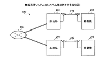
図1は、無線通信システムの機能的構成の一例を示す説明図である。図1に示すように、無線通信システム100は、複数の周波数帯域を同時に用いて無線通信を行う第1通信装置110および第2通信装置120を含む。第1通信装置110は、抽出部111と、送信部112と、取得部113と、を有する。第2通信装置120は、受信部121と、送信部122と、を有する。
(Example of functional configuration of wireless communication system)
FIG. 1 is an explanatory diagram illustrating an example of a functional configuration of a wireless communication system. As illustrated in FIG. 1, the
抽出部111は、複数の周波数帯域の中から所定の周波数帯域幅に含まれる2以上の周波数帯域を抽出する。周波数帯域とは、コンポーネントキャリアの周波数チャネル幅である。所定の周波数帯域幅とは、少なくとも隣接または近傍の2以上の周波数帯域が存在し且つ必ずしも全ての周波数帯域が存在することのない周波数帯域幅である。たとえば、隣接する周波数帯域または近傍の周波数帯域は、減衰やフェージングといった伝搬路特性が類似する。言い換えれば、抽出部111は、伝搬路特性が類似する2以上の周波数帯域を抽出する。また、抽出するとは、グルーピングするという趣旨を含む。つまり、抽出部111は、伝搬路特性が類似する2以上の周波数帯域をグルーピングする、ともいえる。 The extraction unit 111 extracts two or more frequency bands included in a predetermined frequency bandwidth from a plurality of frequency bands. The frequency band is the frequency channel width of the component carrier. The predetermined frequency bandwidth is a frequency bandwidth in which at least two adjacent or neighboring frequency bands exist and not all frequency bands exist. For example, adjacent frequency bands or nearby frequency bands have similar channel characteristics such as attenuation and fading. In other words, the extraction unit 111 extracts two or more frequency bands having similar propagation path characteristics. The term “extract” includes the meaning of grouping. That is, it can be said that the extraction unit 111 groups two or more frequency bands having similar propagation path characteristics.
送信部112は、抽出された周波数帯域のうちの少なくともいずれかの周波数帯域によって第2通信装置120から受信した無線信号の品質の測定結果に基づく、2以上の周波数帯域の各無線信号の送信電力の共通の制御情報を第2通信装置120へ送信する。無線信号の品質の測定結果は、抽出部111によって抽出された2以上の周波数帯域のうちの少なくともいずれかの周波数帯域のものであればよい。たとえば、抽出部111によって抽出された2以上の周波数帯域のうちの1つの周波数帯域のものでもよいし、複数の周波数帯域の平均でもよい。これは、伝搬路特性が類似する2以上の周波数帯域では、第2通信装置120からの無線信号の測定結果も類似する傾向にあるためである。
The
また、抽出部111によって抽出された2以上の周波数帯域の全ての周波数帯域について第2通信装置120からの無線信号の品質を測定すれば、各無線帯域について無線信号の品質の変化を知ることの測定結果の精度を向上させることができる。伝搬路特性が類似する2以上の周波数帯域では、増減させる送信電力がそれぞれ同様の傾向になる。そのため、送信部112は、上述の無線信号の品質の測定結果に基づいて、伝搬路特性が類似する2以上の周波数帯域の各無線信号の送信電力の共通の制御情報を第2通信装置120へ送信する。
Further, if the quality of the radio signal from the
制御情報は、送信電力を増加または減少させる正負を示す情報や、送信電力の増加量または減少量を示す情報や、送信電力の値そのものを示す情報などである。共通の制御情報と2以上の周波数帯域とは、対応付けられて、第2通信装置120へ送信される。たとえば、送信部112は、抽出部111によって抽出されたn個の周波数帯域について、1個の制御情報を送信する。
The control information includes information indicating whether the transmission power is increased or decreased, information indicating an increase or decrease in the transmission power, information indicating the transmission power value itself, and the like. The common control information and the two or more frequency bands are associated with each other and transmitted to the
第2通信装置120の受信部121は、第1通信装置110によって送信された制御情報を受信する。具体的には、受信部121は、送信電力の共通の制御情報と2以上の周波数帯域とが対応付けられた情報を受信する。第2通信装置120の送信部122は、受信部121によって第1通信装置110から受信された共通の制御情報を用いて送信電力を制御した2以上の周波数帯域の各無線信号を第1通信装置110へ送信する。
The receiving
このように、第1通信装置110の送信部112は、共通の制御情報を第2通信装置120へ送信することにより、第2通信装置120に、共通の制御情報を用いて送信電力を制御した2以上の周波数帯域の各無線信号を第1通信装置110へ送信させる。無線通信システム100では、伝搬路特性が類似する2以上の周波数帯域に対して1個の送信電力の制御情報によって送信電力を制御することが可能な送信電力制御情報省略モードが行われる。
As described above, the
また、送信部112は、複数の周波数帯域のうちの抽出部111によって抽出されなかった周波数帯域のそれぞれについて、第2通信装置120から受信した無線信号の品質の測定結果に基づく、各無線信号の送信電力の制御情報を第2通信装置120へ送信する。言い換えれば、送信部112は、たとえば、伝搬路特性が類似せずにグルーピングされなかった周波数帯域については、それぞれ個別の無線信号の制御情報を送信する。送信部112は、たとえば抽出部111によって抽出されなかったm個の周波数帯域について、m個の制御情報を送信する。
In addition, the
第2通信装置120の受信部121は、抽出部111によって抽出されなかった周波数帯域のそれぞれについての無線信号の送信電力の制御情報を受信する。送信部122は、受信部121によって受信された制御情報を用いて送信電力を制御した、抽出部111によって抽出されなかった周波数帯域の無線信号を第1通信装置110へ送信する。
The receiving
また、抽出部111は、複数の周波数帯域の中から、所定の周波数帯域幅に含まれ且つ各周波数帯域についての個別の送信電力の累積制御量がそれぞれ所定量以下である2以上の周波数帯域を抽出する。累積制御量が所定量以下とは、送信電力の増減させる変化が少なく電力が安定していることである。つまり、抽出部111は、送信電力の増減が安定しており、伝搬路特性が類似する2以上の周波数帯域を抽出する。 In addition, the extraction unit 111 selects two or more frequency bands that are included in a predetermined frequency bandwidth and have a cumulative control amount of individual transmission power for each frequency band that is less than or equal to a predetermined amount from among a plurality of frequency bands. Extract. The cumulative control amount being equal to or less than a predetermined amount means that the power is stable with little change in transmission power. In other words, the extraction unit 111 extracts two or more frequency bands in which the increase or decrease in transmission power is stable and the propagation path characteristics are similar.
また、抽出部111は、複数の周波数帯域の中から、所定の周波数帯域幅に含まれ且つ第2通信装置120から受信した無線信号の品質がそれぞれ所定品質以上である2以上の周波数帯域を抽出する。無線信号の品質の測定結果が所定品質以上とは、品質が安定していることである。つまり、抽出部111は、無線信号の品質が安定しており、伝搬路特性が類似する2以上の周波数帯域を抽出する。無線信号の品質には、たとえばRSSI(Received Signal Strength Indicator:受信信号強度)を用いることができる。
In addition, the extraction unit 111 extracts two or more frequency bands that are included in a predetermined frequency bandwidth and that each of the quality of the radio signal received from the
また、抽出部111は、2以上の周波数帯域を周期的に抽出する。周期的とは、たとえば所定時間おきである。これにより、グルーピングする周波数帯域を逐次更新することができ、送信電力制御情報省略モードを継続および中止することができる。 The extraction unit 111 periodically extracts two or more frequency bands. Periodic is, for example, every predetermined time. Thereby, the frequency band to group can be updated sequentially, and transmission power control information omission mode can be continued and stopped.
また、抽出部111は、複数の周波数帯域の中から、複数の周波数帯域のうちの少なくともいずれかの周波数帯域の中心周波数に応じた周波数帯域幅に含まれる2以上の周波数帯域を抽出する。たとえば、周波数帯域の中心周波数が高周波数である場合、信号の直進性がよくなり信号が回り込みやすくなるため、周波数帯域の中心周波数が低周波数である場合に比べて、たとえば信号品質が低下しやすくなる。そのため、周波数帯域の中心周波数が高周波数である場合、周波数帯域の中心周波数が低周波数である場合に比べて、狭い周波数帯域幅とする。 In addition, the extraction unit 111 extracts two or more frequency bands included in the frequency bandwidth corresponding to the center frequency of at least one of the plurality of frequency bands from the plurality of frequency bands. For example, when the center frequency of the frequency band is high, the straightness of the signal is improved and the signal easily wraps around. Therefore, for example, signal quality is likely to deteriorate compared to the case where the center frequency of the frequency band is low. Become. For this reason, when the center frequency of the frequency band is high, the frequency band is narrower than when the center frequency of the frequency band is low.
また、第2通信装置120が移動局の場合、取得部113は、第2通信装置120の移動速度を示す情報を取得する。抽出部111は、複数の周波数帯域の中から、取得部113によって取得された情報が示す移動速度に応じた周波数帯域幅に含まれる2以上の周波数帯域を抽出する。たとえば、第2通信装置120の移動速度が速くなると、移動速度が遅い場合や停止している場合に比べて、たとえば信号品質が低下しやすくなる。そのため、第2通信装置120の移動速度が速くなると、狭い周波数帯域幅とする。たとえば、第2通信装置120の移動速度が閾値以上となった場合に、周波数帯域幅を狭くしてもよい。
When the
また、取得部113は、第1通信装置110と第2通信装置120との間の電波の遮蔽度合いを示す情報を取得する。抽出部111は、複数の周波数帯域の中から、取得部113によって取得された情報が示す遮蔽度合いに応じた周波数帯域幅に含まれる2以上の周波数帯域を抽出する。電波の遮蔽度合いとは、たとえば、高層ビルが乱立するような場所では、高層ビルが乱立しない場所に比べて、たとえば信号品質が低下しやすくなる。
In addition, the
そのため、第1通信装置110と第2通信装置120との間の電波の遮蔽度合いが高くなると、狭い周波数帯域幅とする。遮蔽度合いは、第2通信装置120の位置情報と、地物情報を含む地図データと、から得ることができる。つまり、取得部113は、第2通信装置120の位置情報と地物情報を含む地図データとに基づく遮蔽度合いを取得する。
Therefore, when the shielding degree of the radio wave between the
また、抽出部111は、信号の変調方式に応じた周波数帯域幅に含まれる2以上の周波数帯域を抽出してもよい。信号の変調方式とは、たとえば、QAM(Quadrature Amplitude Modulation)や、QPSK(Quadrature Phase Shift Keying)などである。変調方式に応じて、信号品質が低下のしやすさが異なる。そのため、信号の変調方式に応じて周波数帯域幅を変えてもよい。 Further, the extraction unit 111 may extract two or more frequency bands included in the frequency bandwidth corresponding to the signal modulation method. Examples of the signal modulation method include QAM (Quadrature Amplitude Modulation) and QPSK (Quadrature Phase Shift Keying). Depending on the modulation method, the signal quality is likely to decrease. Therefore, the frequency bandwidth may be changed according to the signal modulation method.
(無線通信システムのシステム構成例)
図2は、無線通信システムのシステム構成例を示す説明図である。図2に示すように、無線通信システム100は、複数の基地局201と、複数の移動機202と、を有する。基地局201は、たとえば、図1の第1通信装置110である。また、移動機202は、図1の第2通信装置120である。各基地局201は、ネットワーク210を介してそれぞれ接続されている。たとえば、ネットワーク210は、インターネット、LAN(Local Area Network)、WAN(Wide Area Network)などである。
(System configuration example of wireless communication system)
FIG. 2 is an explanatory diagram illustrating a system configuration example of a wireless communication system. As shown in FIG. 2, the
また、基地局201は、無線通信ネットワーク220を介して移動機202と接続されている。基地局201は、電波が届く範囲を示すセル内にある移動機202とネットワーク210により接続される。基地局201は、ネットワーク210からのデータを無線インタフェースに合うデータフォーマットに変換して自セル内にある移動機202に無線周波数で搬送する。また、基地局201は、無線周波数で搬送される移動機202らのデータを受信して有線インタフェースに合うデータフォーマットに変換し、無線通信ネットワーク220に搬送する。
The
移動機202は、たとえば、携帯電話、スマートフォン、タブレットコンピュータ、PC(Personal Computer)などである。移動機202は、無線通信ネットワーク220によって基地局201に接続することにより、たとえば、通話機能を有するほか、各種データを基地局201からダウンロードしたり基地局201へアップロードしたりする。
The
(基地局と移動機との間で送受されるコンポーネントキャリアの一例)
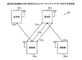
図3は、基地局と移動機との間で送受されるコンポーネントキャリアの一例を示す説明図である。図3に示すように、基地局201aは、移動機202aに接続されている。また、基地局201bは、移動機202aと移動機202bとに接続されている。
(Example of component carrier sent and received between base station and mobile device)
FIG. 3 is an explanatory diagram showing an example of a component carrier transmitted / received between a base station and a mobile device. As shown in FIG. 3, the
ここで、無線通信データ通信の速度は、システム帯域幅によってその上限が設定されている。たとえば、LTE(Long Term Evolution)における最大システム幅は20MHzである。これに対して、より高速なデータ通信を実現するため、キャリアアグリゲーション(CA:Carrier Aggregation)と呼ばれる技術がある。キャリアアグリゲーションは、コンポーネントキャリア(CC:Component Carrier)と呼ばれる複数のLTEキャリアを同時に用いて通信を行うことにより、20MHzを超える広帯域伝送を可能にする。本明細書において、コンポーネントキャリアを適宜「CC」と称する。 Here, the upper limit of the speed of wireless communication data communication is set by the system bandwidth. For example, the maximum system width in LTE (Long Term Evolution) is 20 MHz. On the other hand, in order to realize higher-speed data communication, there is a technology called carrier aggregation (CA: Carrier Aggregation). Carrier aggregation enables broadband transmission over 20 MHz by performing communication using a plurality of LTE carriers called component carriers (CC) at the same time. In this specification, the component carrier is appropriately referred to as “CC”.
たとえば、同じ周波数バンドで、周波数方向に連続した2つのコンポーネントキャリアでキャリアアグリゲーションすることが可能である。なお、異なる周波数バンドで不連続のコンポーネントキャリアを、たとえば最大5つキャリアアグリゲーションすることにより、最大100MHzの帯域幅を実現することも可能である。 For example, carrier aggregation can be performed using two component carriers that are continuous in the frequency direction in the same frequency band. It is also possible to realize a maximum bandwidth of 100 MHz by, for example, aggregating up to five discontinuous component carriers in different frequency bands.
ここで、キャリアアグリゲーション時に、コンポーネントキャリアにおいて、高速送信電力制御(TPC)をそれぞれ別個に行ったとする。送信電力の制御には、上りリンク(Uplink)も下りリンク(Downlink)も、開ループ送信電力制御と、閉ループ送信電力制御とが併用される。なお、本明細書において、Uplinkについては適宜「UL」と称し、Downlinkについては「DL」と称する。 Here, it is assumed that high-speed transmission power control (TPC) is separately performed in the component carrier at the time of carrier aggregation. For the control of the transmission power, the open loop transmission power control and the closed loop transmission power control are used in combination for both the uplink (Uplink) and the downlink (Downlink). In this specification, Uplink is appropriately referred to as “UL”, and Downlink is referred to as “DL”.
開ループ送信電力制御は、受信側で受信電力に基づいて伝搬ロスを推定し、自局の送信電力を自立的に決定する手法であり、たとえば閉ループ送信電力制御を適用することができない場合に用いられる。閉ループ送信電力制御は、DPCCH(Dedicated Physical Control Channel)上のTPCビットとしてフィードバックされる制御情報を用いて自局の送信電力を決定する手法である。 Open-loop transmission power control is a technique for estimating propagation loss based on received power on the receiving side and autonomously determining its own transmission power. For example, it is used when closed-loop transmission power control cannot be applied. It is done. Closed loop transmission power control is a method of determining the transmission power of the local station using control information fed back as a TPC bit on a DPCCH (Dedicated Physical Control Channel).
開ループ送信電力制御では、コンポーネントキャリアに対して目標電力が設定される。閉ループ送信電力制御では、上りリンクの送信電力制御の場合、コンポーネントキャリアに対して基地局201が無線回線品質を測定する。そして、基地局201は、測定結果に応じて、無線回線品質を満たす送信電力となるよう、制御チャネルを用いて移動機202に通知する。通知を受けた移動機202は、通知に基づいて送信電力を制御する。
In the open loop transmission power control, a target power is set for the component carrier. In the closed-loop transmission power control, in the case of uplink transmission power control, the
また、下りリンクの送信電力制御の場合、コンポーネントキャリアに対して移動機202が下り無線回線品質を測定する。移動機202は、測定結果に応じて、無線回線品質を満たす送信電力となるよう、制御チャネルを用いて基地局201に通知する。通知を受けた基地局201は、通知に基づいて送信電力を制御する。
Also, in the case of downlink transmission power control, the
ここで、LTEシステムにおける上りリンクで送信される信号(PUSCH(Physical Uplink Shared Channel))などの送信電力は、開ループ送信電力制御と、閉ループ送信電力制御との組合せによって制御される。なお、上りリンクで送信される信号は、PUSCHのほかにも、PUCCH(Physical Uplink Control Channel)、SRS(Sounding Reference Signal)などの信号がある。 Here, transmission power of a signal (PUSCH (Physical Uplink Shared Channel)) transmitted in the uplink in the LTE system is controlled by a combination of open-loop transmission power control and closed-loop transmission power control. Signals transmitted on the uplink include signals such as PUCCH (Physical Uplink Control Channel) and SRS (Sounding Reference Signal) in addition to PUSCH.
開ループ送信電力制御は、基地局201が比較的長周期で通知するパラメータ(下記(1)式のαなど)、および、移動機202が測定する伝搬損失(PL)による制御である。閉ループ送信電力制御は、基地局201と移動機202との間の通信状況に基づいて基地局201が比較的短周期で通知するTPCコマンドによる制御である。通信状況とは、たとえば、基地局201での受信SINR(信号対雑音干渉電力比:Signal to Interference plus Noise Power Ratio)が用いられる。
The open loop transmission power control is control based on a parameter (such as α in the following equation (1)) notified by the
PUSCHの送信電力制御方式を例として説明すると、開ループ送信電力制御において、PUSCHの送信電力は下記(1)式によって算出される。 The PUSCH transmission power control method will be described as an example. In the open loop transmission power control, the PUSCH transmission power is calculated by the following equation (1).
PPUSCH(i)=min{PCMAX,10log10(MPUSCH(i))+P0_PUSCH(j)+α(j)・PL+ΔTF(i)+f(i)}…(1)式 PPUSCH (i) = min {PCMAX, 10log10 (MPUSCH (i)) + P0_PUSCH (j) + α (j) · PL + ΔTF (i) + f (i)} (1)
PCMAXは最大送信電力である。MPUSCHは送信帯域幅である。P0_PUSCHは目標受信電力にかかるパラメータである。αはフラクショナルTPCの重み係数である。PLはパスロス測定値である。ΔTFはMCSに依存するオフセットである。f(i)はTPCコマンドによる補正値である。 PCMAX is the maximum transmission power. MPUSCH is the transmission bandwidth. P0_PUSCH is a parameter related to the target received power. α is a weighting factor of fractional TPC. PL is a path loss measurement value. ΔTF is an offset depending on MCS. f (i) is a correction value by the TPC command.
また、基地局201と移動機202との間で行われる閉ループ送信電力制御において、上りリンク送信電力では、たとえば、基地局201において平均化時間tで平均化した受信SINRと目標受信SINRとの差分を計算する。そして、この差分をTPCコマンドとして移動機202に通知することにより、移動機202の送信電力を制御している。
Further, in the closed-loop transmission power control performed between the
このような構成では、キャリアアグリゲーション時に、TPC(送信電力制御)を行う場合には、コンポーネントキャリア数(n)に比例して必要とするTPCメッセージがn倍となり、制御チャネルの負荷が増える。 In such a configuration, when TPC (transmission power control) is performed at the time of carrier aggregation, the required TPC message is multiplied by n in proportion to the number of component carriers (n), and the load on the control channel increases.
また、LTEシステムにおける下りリンクの送信電力制御は、たとえば、下記(2)式によって算出される。 Also, downlink transmission power control in the LTE system is calculated by, for example, the following equation (2).
P(k)=P(K−1)+PTPC(k)+Pbal(k)…(2)式 P (k) = P (K-1) + PTPC (k) + Pbal (k) (2) equation
P(k)はk回目の送信電力制御時のダウンリンク送信電力である。P(K−1)はその一つ前(K−1回目)のときの送信電力である。Pbal(k)は下り送信電力バランスを考慮したときの調整値である。PTPC(k)はk回目の送信電力制御における電力変化量であり、上りDPCCHのTPCフィールドを使って移動機端末によって制御される。 P (k) is the downlink transmission power at the k-th transmission power control. P (K-1) is the transmission power at the previous time (K-1 time). Pbal (k) is an adjustment value when considering the downlink transmission power balance. PTPC (k) is a power change amount in the k-th transmission power control, and is controlled by the mobile terminal using the TPC field of the uplink DPCCH.
このような構成では、上りリンクのときと同様、キャリアアグリゲーション時にコンポーネントキャリア数に比例して、送信電力制御のための情報量が増えてしまい、制御チャネルの負荷が増える。 In such a configuration, as in the uplink, the amount of information for transmission power control increases in proportion to the number of component carriers during carrier aggregation, and the load on the control channel increases.
そこで、本実施の形態では、伝搬路特性が類似するグルーピングした複数のコンポーネントキャリアに対して一の制御情報によって送信電力を制御することにより、送信電力制御のための情報量を減らしつつ、無線信号の品質が低下することを抑える。 Therefore, in the present embodiment, by controlling transmission power with a single piece of control information for a plurality of grouped component carriers having similar propagation path characteristics, the amount of information for transmission power control is reduced, and a radio signal is transmitted. To prevent the quality of the product from degrading.
図3に示すように、各基地局201a,201bと、移動機202a,202bとの間では、異なる周波数のコンポーネントキャリアCCa,CCb,CCc,CCd,CCeが用いられている。基地局201aは、移動機202aとの間で、コンポーネントキャリアCCdを用いている。基地局201bは、移動機202aとの間で、コンポーネントキャリアCCa,CCb,CCcを用いている。基地局201bは、移動機202bとの間で、コンポーネントキャリアCCeを用いている。
As shown in FIG. 3, component carriers CCa, CCb, CCc, CCd, CCe having different frequencies are used between the
(周波数領域上におけるCCの相対関係の一例)
図4は、周波数領域上におけるCCの相対関係の一例を示す説明図である。図4に示すように、周波数領域上に、コンポーネントキャリアCCa,CCb,CCc,CCd,CCeが表されている。コンポーネントキャリアCCa,CCb,CCc,CCeは、基準周波数(たとえばCCbの中心周波数)を中心にして、いずれも所定の周波数帯域幅に含まれる。コンポーネントキャリアCCdは、基準周波数を中心にして、所定の周波数帯域幅にない周波数である。
(Example of relative relationship of CC on frequency domain)
FIG. 4 is an explanatory diagram showing an example of the relative relationship of CCs on the frequency domain. As shown in FIG. 4, component carriers CCa, CCb, CCc, CCd, and CCe are represented on the frequency domain. The component carriers CCa, CCb, CCc, and CCe are all included in a predetermined frequency bandwidth around a reference frequency (for example, the center frequency of CCb). The component carrier CCd is a frequency that is not in a predetermined frequency bandwidth around the reference frequency.
また、コンポーネントキャリアCCeは、基準周波数を中心にして、所定の周波数帯域幅にあるものの、移動機202が異なる。そのため、コンポーネントキャリアCCa,CCb,CCcの3つについてはグルーピングして、閉ループ送信電力制御において一つのTPC制御情報によって送信電力を制御(送信電力制御情報省略モードによる制御)するようにしている。これにより、3つのコンポーネントキャリアCCa,CCb,CCcについて、アップリンクまたはダウンリンク時に、無線品質を損なうことなく、送信電力の制御に要する送信電力制御情報量を3分の1に抑えることができる。
Further, the component carrier CCe has a predetermined frequency bandwidth around the reference frequency, but the
(基地局のハードウェア構成の一例)
図5は、基地局のハードウェア構成の一例を示す図である。図5に示すように、基地局201は、CPU501と、メモリ502と、ユーザインタフェース503と、通信インタフェース504と、を有する。CPU501、メモリ502、ユーザインタフェース503および通信インタフェース504は、バス509によって接続されている。
(Example of base station hardware configuration)
FIG. 5 is a diagram illustrating an example of a hardware configuration of the base station. As illustrated in FIG. 5, the
CPU(Central Processing Unit)501は、基地局201の全体の制御を司る。メモリ502には、たとえばメインメモリおよび補助メモリが含まれる。メインメモリは、たとえばRAM(Random Access Memory)である。メインメモリは、CPU501のワークエリアとして使用される。
A CPU (Central Processing Unit) 501 governs overall control of the
補助メモリは、たとえば磁気ディスク、光ディスク、フラッシュメモリなどの不揮発メモリである。補助メモリには、基地局201を動作させる各種のプログラムが記憶されている。補助メモリに記憶されたプログラムは、メインメモリにロードされてCPU501によって実行される。
The auxiliary memory is, for example, a nonvolatile memory such as a magnetic disk, an optical disk, or a flash memory. Various programs for operating the
ユーザインタフェース503は、たとえば、ユーザからの操作入力を受け付ける入力デバイスや、ユーザへ情報を出力する出力デバイスなどを含む。入力デバイスは、たとえば、タッチパネル、キー(たとえばキーボード)、マイク、リモコンなどによって実現することができる。出力デバイスは、たとえば、タッチパネルやディスプレイやスピーカなどによって実現することができる。ユーザインタフェース503は、CPU501によって制御される。
The
通信インタフェース504は、たとえば、無線や有線によって基地局201の外部装置との間で通信を行うインタフェースである。通信インタフェース504は、CPU501によって制御される。
The
図1を用いて説明した第1通信装置110の抽出部111と、送信部112と、取得部113とは、CPU501によって実現することができる。すなわち、CPU501が各種プログラムを実行することにより、各部の機能を実現することができる。
The extraction unit 111, the
(移動機のハードウェア構成の一例)
図6は、移動機のハードウェア構成の一例を示す図である。図6に示すように、移動機202は、CPU601と、メモリ602と、ユーザインタフェース603と、通信インタフェース604と、位置情報取得装置605と、を有する。CPU601と、メモリ602と、ユーザインタフェース603と、通信インタフェース604と、位置情報取得装置605とは、バス609によって接続されている。
(Example of hardware configuration of mobile device)
FIG. 6 is a diagram illustrating an example of a hardware configuration of a mobile device. As illustrated in FIG. 6, the
CPU601は、移動機202の全体の制御を司る。メモリ602には、たとえばメインメモリおよび補助メモリが含まれる。メインメモリは、たとえばRAMである。メインメモリは、CPU601のワークエリアとして使用される。
The
補助メモリは、たとえば磁気ディスク、光ディスク、フラッシュメモリなどの不揮発メモリである。補助メモリには、移動機202を動作させる各種のプログラムが記憶されている。補助メモリに記憶されたプログラムは、メインメモリにロードされてCPU601によって実行される。
The auxiliary memory is, for example, a nonvolatile memory such as a magnetic disk, an optical disk, or a flash memory. Various programs for operating the
ユーザインタフェース603は、たとえば、ユーザからの操作入力を受け付ける入力デバイスや、ユーザへ情報を出力する出力デバイスなどを含む。入力デバイスは、たとえば、タッチパネル、キー(たとえばキーボード)、マイク、リモコンなどによって実現することができる。出力デバイスは、たとえば、タッチパネルやディスプレイやスピーカなどによって実現することができる。ユーザインタフェース603は、CPU601によって制御される。
The
通信インタフェース604は、たとえば、無線や有線によって移動機202の外部装置との間で通信を行うインタフェースである。通信インタフェース604は、CPU601によって制御される。位置情報取得装置605は、移動機202の位置情報を取得する。位置情報取得装置605としては、たとえばGPS(Global Positioning System)衛星からのGPS情報を基に位置情報を取得する装置が挙げられる。
The
図1を用いて説明した第2通信装置120の、受信部121と、送信部122とは、CPU601によって実現することができる。すなわち、CPU601が各種プログラムを実行することにより、各部の機能を実現することができる。
The
(基地局の機能的構成の詳細構成の一例)
図7は、基地局の機能的構成の詳細構成の一例を示す説明図である。図7においては、2つのコンポーネントキャリアCC1,CC2を用いる場合について説明する。
(Example of detailed configuration of functional configuration of base station)
FIG. 7 is an explanatory diagram showing an example of a detailed configuration of the functional configuration of the base station. In FIG. 7, a case where two component carriers CC1 and CC2 are used will be described.
図7に示すように、基地局201は、CC1受信部701aと、CC2受信部701bと、CC1復調・復号部702aと、CC2復調・復号部702bと、無線回線品質測定部703と、上り送信電力制御方法判定部704と、を有する。また、基地局201は、UL(Uplink)CCグルーピングテーブル705と、上り送信電力制御方法通知部706と、上り送信電力制御部707と、上り送信電力制御信号作成部708と、を有する。
As shown in FIG. 7, the
さらに、基地局201は、CC1符号化・変調部709aと、CC2符号化・変調部709bと、CC1送信部710aと、CC2送信部710bと、送信電力情報検出部711と、下り送信電力制御方法判定部712と、を有する。また、基地局201は、DL(Downlink)CCグルーピングテーブル713と、下り送信電力制御部714と、CC1振幅調整部715aと、CC2振幅調整部715bと、CC1格納部716aと、CC2格納部716bと、を有する。
Further, the
ULCCグルーピングテーブル705およびDLCCグルーピングテーブル713を除く各部は、図5に示したCPU501によって実現される。すなわち、CPU501が各種プログラムを実行することにより、各部の機能を実現する。また、ULCCグルーピングテーブル705およびDLCCグルーピングテーブル713は、メモリ502によって実現される。
Each unit excluding the ULCC grouping table 705 and the DLCC grouping table 713 is realized by the
CC1受信部701aは、コンポーネントキャリアCC1による信号を受信する。CC1受信部701aは、受信したコンポーネントキャリアCC1による信号をC1復調・復号部702aへ出力する。CC2受信部701bは、コンポーネントキャリアCC2による信号を受信する。CC2受信部701bは、受信したコンポーネントキャリアCC2による信号をC2復調・復号部702bへ出力する。
The
CC1復調・復号部702aは、CC1受信部701aからのコンポーネントキャリアCC1による信号を復調および復号する。CC1復調・復号部702aは、復調および復号した信号を、無線回線品質測定部703および送信電力情報検出部711へ出力する。
The CC1 demodulator /
CC2復調・復号部702bは、CC2受信部701bからのコンポーネントキャリアCC2による信号を復調および復号する。CC2復調・復号部702bは、復調および復号した信号を、無線回線品質測定部703および送信電力情報検出部711へ出力する。
The CC2 demodulator /
無線回線品質測定部703は、コンポーネントキャリアCC1およびコンポーネントキャリアCC2について、それぞれ上り無線回線品質を測定する。無線回線品質測定部703は、上り無線回線品質の測定結果を上り送信電力制御方法判定部704および上り送信電力制御部707へ出力する。
Radio channel
上り送信電力制御方法判定部704は、上り送信電力について、既存の制御方法に加えて、無線回線品質測定部703の測定結果に基づいて、上り送信電力制御情報省略モードの開始および終了を判定する。上り送信電力制御情報省略モードとは、周波数が隣接するコンポーネントキャリアをグルーピングして、閉ループ送信電力制御においてグループ毎に一つのTPC制御情報を用いて送信電力を制御するモードである。
The uplink transmission power control
また、上り送信電力制御方法判定部704は、上り送信電力の制御方法を判定する。上り送信電力制御方法判定部704は、ULCCグルーピングテーブル705のCCグルーピング情報の生成および更新を行う。具体的には、上り送信電力制御方法判定部704は、無線回線品質測定部703による測定結果を用いて、閾値範囲内の新たなコンポーネントキャリアがある場合に、これをULCCグループに追加するために、ULCCグルーピングテーブル705を更新する。また、上り送信電力制御方法判定部704は、上り無線品質が所定の閾値範囲から外れた(下限値以下となる)コンポーネントキャリアがあった場合、これをULCCグループから削除するために、ULCCグルーピングテーブル705を更新する。
Also, uplink transmission power control
ULCCグルーピングテーブル705の詳細については後述するが、移動機ID、コンポーネントキャリアID(CCID)、グループIDなどのCCグルーピング情報が記憶される。CCグルーピング情報は、どの移動機202がどのULCCグループに属しているかを示す。
Although details of the ULCC grouping table 705 will be described later, CC grouping information such as a mobile device ID, a component carrier ID (CCID), and a group ID is stored. The CC grouping information indicates which
上り送信電力制御方法通知部706は、上り送信電力制御方法判定部704の判定結果に基づき、上り送信電力制御情報省略モードの開始および終了の合図を示す情報を生成して送信電力制御信号作成部708へ出力する。たとえば、ULCCグルーピングテーブル705が更新された場合、上り送信電力制御方法通知部706は、ULCCグループ毎に、ULCCグルーピングテーブル705を所定のフォーマットで生成して、上り送信電力制御信号作成部708へ出力する。
The uplink transmission power control
上り送信電力制御部707は、無線回線品質測定部703による測定結果および上り送信電力制御方法判定部704による判定結果を用いて、ULCCグループ毎に、上り送信電力制御情報を制御する。上り送信電力制御部707は、上り送信電力制御情報省略モードが開始されると、対象のULCCグループに含まれる一つのCCについてのみTPC制御を行う。TPC制御において、上り送信電力制御部707は、同じULCCグループに含まれる他のコンポーネントキャリアについては、送信電力制御情報の送信を停止させる。上り送信電力制御部707は、ULCCグループ毎の送信電力制御情報を、上り送信電力制御信号作成部708へ出力する。
Uplink transmission
上り送信電力制御信号作成部708は、上り送信電力制御方法通知部706からのコンポーネントキャリアCC1についての上り送信電力制御情報省略モードの開始および終了の合図を示す情報を基に、制御信号を作成する。また、上り送信電力制御信号作成部708は、コンポーネントキャリアCC1についての上り送信電力制御部707から出力された送信電力制御情報を基に、制御信号を作成する。上り送信電力制御信号作成部708は、作成したコンポーネントキャリアCC1についての制御信号をCC1格納部716aへ出力する。
Uplink transmission power control
また、上り送信電力制御信号作成部708は、上り送信電力制御方法通知部706からのコンポーネントキャリアCC2についての上り送信電力制御情報省略モードの開始および終了の合図を示す情報を基に、制御信号を作成する。また、上り送信電力制御信号作成部708は、コンポーネントキャリアCC2についての上り送信電力制御部707から出力された送信電力制御情報を基に、制御信号を作成する。上り送信電力制御信号作成部708は、作成したコンポーネントキャリアCC2についての制御信号をCC2格納部716bへ出力する。
Further, the uplink transmission power control
CC1格納部716aは、上り送信電力制御信号作成部708によって作成されたコンポーネントキャリアCC1についての制御信号を送信データの制御チャネルに格納させる。CC2格納部716bは、上り送信電力制御信号作成部708によって作成されたコンポーネントキャリアCC2についての制御信号を送信データの制御チャネルに格納させる。
The
CC1符号化・変調部709aは、コンポーネントキャリアCC1についての、CC1格納部716aによって制御チャネルに格納された制御信号を符号化および変調し、CC1送信部710aへ出力する。CC2符号化・変調部709bは、コンポーネントキャリアCC2についての、CC2格納部716bによって制御チャネルに格納された制御信号を符号化および変調し、CC2送信部710bへ出力する。
The CC1 encoding /
CC1送信部710aは、CC1符号化・変調部709aによって符号化および変調された信号を移動機202へ送信する。CC2送信部710bは、CC2符号化・変調部709bによって符号化および変調された信号を移動機202へ送信する。
基地局201において下り送信電力制御情報省略モードの開始および終了を判断する構成の場合、送信電力情報検出部711は、移動機202にて生成された、TPC要求を検出する。また、移動機202において下り送信電力制御情報省略モードの開始および終了を判断する構成の場合、送信電力情報検出部711は、移動機202にて生成された下り送信電力制御情報省略モードの開始および終了の合図を示す情報を検出する。また、移動機202においてCCグルーピング情報の更新が行われる場合、送信電力情報検出部711は、移動機202で更新されたCCグルーピング情報の更新情報を検出する。送信電力情報検出部711は、検出した情報を下り送信電力制御方法判定部712へ出力する。
When the
基地局201において下り送信電力制御情報省略モードの開始および終了を判断する場合、下り送信電力制御方法判定部712は、送信電力情報検出部711によって検出された移動機202からのTPC要求を所定期間、CC毎に累積する。そして、下り送信電力制御方法判定部712は、下り送信電力制御情報省略モードの開始および終了を判定し、判定結果を下り送信電力制御部714へ出力する。また、下り送信電力制御方法判定部712は、DLCCグルーピングテーブル713のCCグルーピング情報の生成および更新を行う。
When the
DLCCグルーピングテーブル713の詳細については後述するが、移動機ID、コンポーネントキャリアID(CCID)、グループIDなどのCCグルーピング情報が記憶される。CCグルーピング情報は、どの移動機202がどのDLCCグループに属しているかを示す。
Although details of the DLCC grouping table 713 will be described later, CC grouping information such as a mobile device ID, a component carrier ID (CCID), and a group ID is stored. The CC grouping information indicates which
下り送信電力制御部714は、下り送信電力制御方法判定部712による判定結果に基づいて、DLCCグループ毎に、DL送信電力制御情報省略モードの開始および終了の合図を下り制御チャネルにマッピングする。DLCCグルーピングテーブル713が更新される都度、下り送信電力制御部714は、対象のDLCCグルーピングテーブル713を下り制御チャネルにマッピングする。
Based on the determination result by the downlink transmission power control
下り送信電力制御部714は、制御信号を、CC1振幅調整部715aおよびCC2振幅調整部715bへ出力する。CC1振幅調整部715aは、下り送信電力制御部714からの制御信号に基づいて、CC1データの振幅を調整する。CC1振幅調整部715aは、振幅を調整した制御信号をCC1符号化・変調部709aへ出力する。CC2振幅調整部715bは、下り送信電力制御部714からの制御信号に基づいて、CC2データの振幅を調整する。CC2振幅調整部715bは、振幅を調整した制御信号をCC2符号化・変調部709bへ出力する。
The downlink transmission
CC1符号化・変調部709aは、CC1振幅調整部715aからの制御信号に基づいて、コンポーネントキャリアCC1についての、下り送信電力制御情報省略モードの開始および終了の合図を示す情報を符号化および変調し、CC1送信部710aへ出力する。CC2符号化・変調部709bは、CC2振幅調整部715bからの制御信号に基づいて、コンポーネントキャリアCC2についての、下り送信電力制御情報省略モードの開始および終了の合図を示す情報を、符号化および変調し、CC2送信部710bへ出力する。
The CC1 encoder / modulator 709a encodes and modulates information indicating the start and end signals of the downlink transmission power control information omission mode for the component carrier CC1 based on the control signal from the
(移動機の機能的構成の詳細構成の一例)
図8は、移動機の機能的構成の詳細構成の一例を示す説明図である。図8においては、2つのコンポーネントキャリアCC1,CC2を用いる場合について説明する。
(Example of detailed configuration of functional configuration of mobile device)
FIG. 8 is an explanatory diagram showing an example of a detailed configuration of the functional configuration of the mobile device. In FIG. 8, a case where two component carriers CC1 and CC2 are used will be described.
図8に示すように、移動機202は、CC1受信部801aと、CC2受信部801bと、CC1復調・復号部802aと、CC2復調・復号部802bと、送信電力情報検出部803と、上り送信電力制御方法判定部804とを有する。また、移動機202は、ULCCグルーピングテーブル805と、上り送信電力制御部806と、CC1振幅調整部807aと、CC2振幅調整部807bと、CC1符号化・変調部808aと、CC2符号化・変調部808bと、CC1送信部809aとを有する。
As shown in FIG. 8, the
また、移動機202は、CC2送信部809bと、無線回線品質測定部810と、下り送信電力制御方法判定部811と、DLCCグルーピングテーブル812と、下り送信電力制御方法通知部813と、下り送信電力制御部814とを有する。さらに、移動機202は、下り送信電力制御信号作成部815と、CC1格納部816aと、CC2格納部816bとを有する。
Also, the
ULCCグルーピングテーブル805およびDLCCグルーピングテーブル812を除く各部は、図6に示したCPU601によって実現される。すなわち、CPU601が各種プログラムを実行することにより、各部の機能を実現する。また、ULCCグルーピングテーブル805およびDLCCグルーピングテーブル812は、メモリ602によって実現される。
Each unit excluding the ULCC grouping table 805 and the DLCC grouping table 812 is realized by the
CC1受信部801aは、コンポーネントキャリアCC1による信号を受信する。CC1受信部801aは、受信したコンポーネントキャリアCC1による信号をC1復調・復号部802aへ出力する。CC2受信部801bは、コンポーネントキャリアCC2による信号を受信する。CC2受信部801bは、受信したコンポーネントキャリアCC2による信号をC2復調・復号部802bへ出力する。
The
CC1復調・復号部802aは、CC1受信部801aからのコンポーネントキャリアCC1による信号を復調および復号する。CC1復調・復号部802aは、復調および復号した信号を、送信電力情報検出部803および無線回線品質測定部810へ出力する。
The CC1 demodulator /
CC2復調・復号部802bは、CC2受信部801bからのコンポーネントキャリアCC2による信号を復調および復号する。CC2復調・復号部802bは、復調および復号した信号を、送信電力情報検出部803および無線回線品質測定部810へ出力する。
The CC2 demodulator /
送信電力情報検出部803は、基地局201から送信される、CCグルーピング情報を検出するとともに、コンポーネントキャリアCC1,CC2についての上り送信電力制御情報省略モードの開始および終了の合図を示す情報を検出する。送信電力情報検出部803は、検出した情報を上り送信電力制御方法判定部804へ出力する。
The transmission power
上り送信電力制御方法判定部804は、送信電力情報検出部803からの上り送信電力制御情報省略モードの開始および終了の合図を示す情報にしたがって、送信電力制御情報省略モード時における上り送信電力の制御を行うか否かを判定する。すなわち、上り送信電力制御方法判定部804は、同じULCCグループに含まれるCCに対して、一つのTPC制御情報を共通に適用するか否かを判定する。
The uplink transmission power control
ULCCグルーピングテーブル805は、上り送信電力制御情報省略モードを行うためのCCグルーピング情報が記憶され、基地局201の指示によって生成および更新される。たとえば、ULCCグルーピングテーブル805には、基地局ID、コンポーネントキャリアID(CCID)、グループIDなどのCCグルーピング情報が記憶される。
The ULCC grouping table 805 stores CC grouping information for performing the uplink transmission power control information omission mode, and is generated and updated according to an instruction from the
上り送信電力制御部806は、上り送信電力制御方法判定部804の判定結果に基づいて、上り送信電力制御情報省略モードのときに、同じULCCグループに含まれるCCに対して、一つのTPC制御情報を共通に適用する。上り送信電力制御部806は、ULCCグループ毎のTPC制御情報を、CC1振幅調整部807aおよびCC2振幅調整部807bへ出力する。また、上り送信電力制御部806は、CC1送信部809aおよびCC2送信部809bのアンプのゲインを調整する。
Based on the determination result of the uplink transmission power control
CC1振幅調整部807aは、上り送信電力制御部806からの信号に基づいて、CC1データの振幅を調整する。CC1振幅調整部807aは、振幅を調整した制御信号をCC1符号化・変調部808aへ出力する。CC2振幅調整部807bは、上り送信電力制御部806からの信号に基づいて、CC2データの振幅を調整する。CC2振幅調整部807bは、振幅を調整した制御信号をCC2符号化・変調部808bへ出力する。
The CC1
CC1符号化・変調部808aは、CC1振幅調整部807aからの信号を符号化および変調し、CC1送信部809aへ出力する。CC2符号化・変調部808bは、CC2振幅調整部807bからの信号を符号化および変調し、CC2送信部809bへ出力する。
CC1 encoder / modulator 808a encodes and modulates the signal from
CC1送信部809aは、CC1符号化・変調部808aによって符号化および変調された信号を基地局201へ送信する。CC2送信部809bは、CC2符号化・変調部808bによって符号化および変調された信号を基地局201へ送信する。
The
無線回線品質測定部810は、コンポーネントキャリアCC1およびコンポーネントキャリアCC2について、それぞれ下り無線回線品質を測定する。無線回線品質測定部810は、下り無線回線品質の測定結果を下り送信電力制御方法判定部811および下り送信電力制御部814へ出力する。
Radio channel
下り送信電力制御方法判定部811は、無線回線品質測定部810の測定結果に基づき、DLCCグルーピングテーブル812を更新する。移動機202において下り送信電力制御情報省略モードの開始および終了を判断する構成の場合、下り送信電力制御方法判定部811は、下り送信電力制御情報省略モードの開始および終了を判断する。
The downlink transmission power control
DLCCグルーピングテーブル812は、CCグルーピング情報を記憶し、基地局201の指示によって生成および更新される。新たに割り当てられたCCがある場合や、通信環境の変化によってDLCCグループに追加してもよくなったCCがある場合、基地局201からその旨が通知される。一方、通信環境の変化によって無線品質劣化や過剰が生じ、DLCCグループからCCを削除する場合、その旨が移動機202から基地局201へ通知される。なお、DLCCグルーピングテーブル812は、移動機202にて生成、保持および更新を行って、基地局201にコピーを送信して、基地局201と移動機202とで同期するようにしてもよい。
The DLCC grouping table 812 stores CC grouping information, and is generated and updated according to an instruction from the
移動機202においてDLCCグルーピングテーブル812を移動機202で更新する構成の場合、下り送信電力制御方法通知部813は、DLCCグルーピングテーブル812を更新する度に、その旨を示す情報を下り送信電力制御信号作成部815に出力する。
When the
下り送信電力制御部814は、下り送信電力制御情報省略モードが開始されると、事前の取り決めにしたがって、対象のDLCCグループに含まれる一つのCCに対してのみ、基地局201に対して送信電力制御を行う。下り送信電力制御部814は、基地局201に対して同じDLCCグループに含まれるコンポーネントキャリアについては、送信電力制御情報を停止させる。
When the downlink transmission power control information omission mode is started, the downlink transmission
下り送信電力制御信号作成部815は、下り送信電力制御方法通知部813からのコンポーネントキャリアCC1についての更新情報を基に、制御信号を作成する。また、下り送信電力制御信号作成部815は、コンポーネントキャリアCC1についての下り送信電力制御部814から出力された送信電力制御情報を基に、制御信号を作成する。下り送信電力制御信号作成部815は、作成したコンポーネントキャリアCC1についての制御信号をCC1格納部816aへ出力する。
The downlink transmission power control
また、下り送信電力制御信号作成部815は、下り送信電力制御方法通知部813からのコンポーネントキャリアCC2についての更新情報を基に、制御信号を作成する。また、下り送信電力制御信号作成部815は、コンポーネントキャリアCC2についての下り送信電力制御部814から出力された送信電力制御情報を基に、制御信号を作成する。下り送信電力制御信号作成部815は、作成したコンポーネントキャリアCC2についての制御信号をCC2格納部816bへ出力する。
Further, downlink transmission power control
CC1格納部816aは、下り送信電力制御信号作成部815によって作成されたコンポーネントキャリアCC1についての制御信号を送信データの制御チャネルに格納させる。CC2格納部816bは、下り送信電力制御信号作成部815によって作成されたコンポーネントキャリアCC2についての制御信号を送信データの制御チャネルに格納させる。
The
CC1符号化・変調部808aは、コンポーネントキャリアCC1についての、CC1格納部816aによって制御チャネルに格納された制御信号を符号化および変調し、CC1送信部809aへ出力する。CC2符号化・変調部808bは、コンポーネントキャリアCC2についての、CC2格納部816bによって制御チャネルに格納された制御信号を符号化および変調し、CC2送信部809bへ出力する。
The CC1 encoder / modulator 808a encodes and modulates the control signal stored in the control channel by the
ダウンリンクの場合、基地局201が送信して、移動機202が受信することになる。そのため、全コンポーネントキャリアの無線品質が分かるのは移動機202である。そのため、移動機202がDLCCグルーピングテーブル812(基地局201のDLCCグルーピングテーブル713)を生成して更新してもよい。ただし、移動機202は、基地局201に比べて、処理能力やバッテリ容量などのリソースが最低限に制限される。そのため、本実施の形態では、ダウンリンクについても、基地局201においてDLCCグルーピングテーブル713(移動機202のDLCCグルーピングテーブル812)を生成して更新するようにしている。
In the case of downlink, the
(アップリンクのコンポーネントキャリアのグルーピング例)
図9は、アップリンクのコンポーネントキャリアのグルーピング例を示す説明図である。図9において、(1)は、アップリンクのコンポーネントキャリアCC1〜10は、基地局201の管理下にある全コンポーネントキャリアを示している。
(Example of uplink component carrier grouping)
FIG. 9 is an explanatory diagram illustrating an example of grouping of uplink component carriers. In FIG. 9, (1) shows uplink component carriers CC1 to CC10 that are all component carriers under the control of the
図9において、(2)は、移動機202aに割り当てられたアップリンクのコンポーネントキャリアを示している。具体的には、移動機202aには、コンポーネントキャリアCC1,CC2,CC3,CC9,CC10の5つが割り当てられている。コンポーネントキャリアCC1,CC2についてはCCグループ1にグルーピングされ、また、コンポーネントキャリアCC9,CC10についてはCCグループ2にグルーピングされている。コンポーネントキャリアCC3は、グルーピングされていない。同じCCグループに含まれるコンポーネントキャリアに対しては、アップリンク時の送信電力の制御に際し、共通の(一つの)TPC制御情報が用いられる。
In FIG. 9, (2) indicates an uplink component carrier assigned to the
図9において、(3)は、移動機202bに割り当てられたアップリンクのコンポーネントキャリアを示している。具体的には、移動機202aには、コンポーネントキャリアCC4,CC5,CC6,CC7,CC8の5つが割り当てられている。コンポーネントキャリアCC4,CC5,CC6、CC7についてはCCグループ3にグルーピングされている。コンポーネントキャリアCC8は、グルーピングされていない。同じCCグループに含まれるコンポーネントキャリアに対しては、アップリンク時の送信電力の制御に際し、共通の(一つの)TPC制御情報が用いられる。
In FIG. 9, (3) indicates an uplink component carrier assigned to the
(ダウンリンクのコンポーネントキャリアのグルーピング例)
図10は、ダウンリンクのコンポーネントキャリアのグルーピング例を示す説明図である。図10において、(1)は、コンポーネントキャリアCC1〜10は、基地局201の管理下にあるダウンリンクの全コンポーネントキャリアを示している。
(Example of downlink component carrier grouping)
FIG. 10 is an explanatory diagram illustrating an example of grouping of downlink component carriers. In FIG. 10, (1) shows component carriers CC1 to CC10 that are all downlink component carriers under the control of the
図10において、(2)は、移動機202aに割り当てられたダウンリンクのコンポーネントキャリアを示している。具体的には、移動機202aには、コンポーネントキャリアCC1,CC2,CC3,CC9,CC10の5つが割り当てられている。コンポーネントキャリアCC1,CC2についてはCCグループ1にグルーピングされ、また、コンポーネントキャリアCC9,CC10についてはCCグループ2にグルーピングされている。コンポーネントキャリアCC3は、グルーピングされていない。同じCCグループに含まれるコンポーネントキャリアに対しては、ダウンリンク時の送信電力の制御に際し、共通の(一つの)TPC制御情報が用いられる。
In FIG. 10, (2) shows a downlink component carrier allocated to the
図10において、(3)は、移動機202bに割り当てられたダウンリンクのコンポーネントキャリアを示している。具体的には、移動機202aには、コンポーネントキャリアCC4,CC5,CC6,CC7,CC8の5つが割り当てられている。コンポーネントキャリアCC4,CC5,CC6、CC7についてはCCグループ3にグルーピングされている。コンポーネントキャリアCC8は、グルーピングされていない。同じCCグループに含まれるコンポーネントキャリアに対しては、ダウンリンク時の送信電力の制御に際し、共通の(一つの)TPC制御情報が用いられる。
In FIG. 10, (3) indicates a downlink component carrier assigned to the
(ULCCグルーピングテーブルの一例)
図11は、基地局に記憶されるULCCグルーピングテーブルの一例を示す説明図である。図11において、ULCCグルーピングテーブル705は、たとえば、図5に示したメモリ502などの記憶装置により実現される。ULCCグルーピングテーブル705は、図9に示したアップリンクのコンポーネントキャリアのグルーピング例に対応する。
(Example of ULCC grouping table)
FIG. 11 is an explanatory diagram showing an example of a ULCC grouping table stored in the base station. In FIG. 11, the ULCC grouping table 705 is realized by a storage device such as the
図11に示すようにULCCグルーピングテーブル705は、移動機IDフィールド、送信電力制御情報省略モード対応フィールド、CCIDフィールド、基準CCフラグフィールド、グループIDフィールド、を有する。また、ULCCグルーピングテーブル705は、開始前閉ループ送信電力累積結果フィールド、開始後無線品質判定結果フィールド、を有する。 As shown in FIG. 11, the ULCC grouping table 705 has a mobile station ID field, a transmission power control information omission mode support field, a CCID field, a reference CC flag field, and a group ID field. In addition, the ULCC grouping table 705 includes a pre-start closed loop transmission power accumulation result field and a post-start radio quality determination result field.
これらのフィールドに情報を設定することにより、ULCCグルーピングテーブル705には、ULCCグルーピングデータ1100−1,1100−2,1100−3…,がレコードとして記憶される。ULCCグルーピングデータ1100−1,1100−2,1100−3…,は、それぞれ、移動機ID、送信電力制御情報省略モード対応、CCID、基準CCフラグ、グループID、開始前閉ループ送信電力累積結果および開始後無線品質判定結果の組合せである。 By setting information in these fields, the ULCC grouping table 705 stores ULCC grouping data 1100-1, 1100-2, 1100-3,... As records. ULCC grouping data 1100-1, 1100-2, 1100-3,... Are respectively associated with mobile station ID, transmission power control information omission mode, CCID, reference CC flag, group ID, pre-start closed loop transmission power accumulation result, and start. This is a combination of subsequent radio quality determination results.
ULCCグルーピングテーブル705において、「移動機ID」は、移動機202のIDを表す。「送信電力制御情報省略モード対応」は、送信電力制御情報省略モードの対応の可否を表す。送信電力制御情報省略モード対応フィールドにおいて、「1」は対応を表し、「0」は非対応を表す。送信電力制御情報省略モード対応フィールドには、デフォルトでは、たとえば「1」が記憶されている。「CCID」は、コンポーネントキャリアのIDを表す。
In the ULCC grouping table 705, “mobile device ID” represents the ID of the
「基準CCフラグ」は、基準となってグルーピングされたコンポーネントキャリア(基準CC)であるか否かを表す。基準CCフラグフィールドにおいて、「1」は基準CCを表し、「0」は基準CCではないことを表す。「グループID」は、CCグループのIDを表す。CCグループは、各移動機202に割り当てられたコンポーネントキャリアの中から移動機202毎に行われる。そのため、異なる移動機202間で、それぞれコンポーネントキャリアが同じCCグループになることはない。グループIDは、移動機毎のグループで表すことができ、具体的には、「移動機No.」−「グループNo.」で表すことができる。
The “reference CC flag” indicates whether or not the component carrier (reference CC) is grouped as a reference. In the reference CC flag field, “1” indicates a reference CC, and “0” indicates that it is not a reference CC. “Group ID” represents the ID of the CC group. The CC group is performed for each
「開始前閉ループ送信電力累積結果」は、コンポーネントキャリアがグルーピングされてから開始され、送信電力情報省略モードが開始されるまで累積される送信電力の累積変動量(累積制御量)を表す。「開始後無線品質判定結果」は、無線品質が所定品質に到達しているか否かを表す。たとえば、開始後無線品質判定結果において、「0」は、所定時間または所定回数の送信電力制御情報省略モードによる制御を行った際に、連続して所定品質に到達しないことを表す。開始後無線品質判定結果において、「1」は、所定時間または所定回数のグループ共通送信電力制御を行った際に、連続して所定品質に到達したことを表す。開始後無線品質判定結果が「0」の場合、後にCCグループから除外されることになる。 The “pre-start closed loop transmission power accumulation result” represents a cumulative fluctuation amount (cumulative control amount) of transmission power that is accumulated after component carriers are grouped and is accumulated until the transmission power information omission mode is started. The “starting wireless quality determination result” indicates whether or not the wireless quality has reached a predetermined quality. For example, in the radio quality determination result after the start, “0” indicates that the predetermined quality is not continuously reached when the control is performed in the transmission power control information omission mode for a predetermined time or a predetermined number of times. In the wireless quality determination result after the start, “1” represents that the predetermined quality has been reached continuously when the group common transmission power control is performed for a predetermined time or a predetermined number of times. If the radio quality determination result after the start is “0”, it will be excluded from the CC group later.
(DLCCグルーピングテーブルの一例)
図12は、基地局に記憶されるDLCCグルーピングテーブルの一例を示す説明図である。図12において、DLCCグルーピングテーブル713は、たとえば、図5に示したメモリ502などの記憶装置により実現される。DLCCグルーピングテーブル713は、図10に示したダウンリンクのコンポーネントキャリアのグルーピング例に対応する。以下において、図11のULCCグルーピングテーブル705にて説明した内容と同一の内容については説明を省略する。
(Example of DLCC grouping table)
FIG. 12 is an explanatory diagram showing an example of a DLCC grouping table stored in the base station. In FIG. 12, the DLCC grouping table 713 is realized by a storage device such as the
DLCCグルーピングテーブル713には、DLCCグルーピングデータ1200−1,1200−2,1200−3…,がレコードとして記憶される。DLCCグルーピングデータ1200−1,1200−2,1200−3…,は、それぞれ、移動機ID、送信電力制御情報省略モード対応、CCID、基準CCフラグ、グループID、開始前閉ループ送信電力累積結果および開始後無線品質判定結果の組合せである。 In the DLCC grouping table 713, DLCC grouping data 1200-1, 1200-2, 1200-3,... Are stored as records. DLCC grouping data 1200-1, 1200-2, 1200-3, ..., respectively, corresponds to mobile station ID, transmission power control information omission mode, CCID, reference CC flag, group ID, pre-start closed loop transmission power accumulation result, and start This is a combination of subsequent radio quality determination results.
(基地局が行う上り送信電力制御情報省略モード時の送信電力制御処理の一例)
図13は、基地局が行う上り送信電力制御情報省略モード時の送信電力制御処理の一例を示すフローチャートである。図13に示すように、基地局201は、ULCCグルーピングテーブル705(図11参照)を作成する(ステップS1301)。次に、基地局201は、UL送信電力を累積し、不適切にグルーピングされたCCをグループから外す(ステップS1302)。
(An example of transmission power control processing in the uplink transmission power control information omission mode performed by the base station)
FIG. 13 is a flowchart illustrating an example of transmission power control processing performed in the uplink transmission power control information omission mode performed by the base station. As illustrated in FIG. 13, the
次に、基地局201は、ULCCグルーピングテーブル705を更新する(ステップS1303)。具体的には、基地局201は、ULCCグルーピングテーブル705において、通信に使われなくなるCCを削除したり、新規のCCを追加したり、外したCCを最適なグループに追加したりする。
Next, the
次に、基地局201は、上り送信電力制御情報省略モード(図13以降の各図面では「上り省略モード」と記載)を開始するか否かを判断する(ステップS1304)。基地局201は、たとえば、所定時間内において、それぞれのCCに対するTPCコマンドによる累積電力変化量(累積制御量)を集計し、それぞれのCCについての累積結果の最大差分が所定の閾値以下のときに上り送信電力制御情報省略モードを開始すると判断する。
Next, the
上り送信電力制御情報省略モードを開始しない場合(ステップS1304:No)、基地局201は、ステップS1302の処理に移行させる。上り送信電力制御情報省略モードを開始する場合(ステップS1304:Yes)、上り送信電力制御情報省略モードの開始合図を示す情報を全ての移動機202へ送信する(ステップS1305)。
When the uplink transmission power control information omission mode is not started (step S1304: No), the
次に、基地局201は、ACK信号を返信しない移動機202については、ULCCグルーピングテーブル705の「送信電力制御情報省略モード対応」フィールドを「0:非対応」に更新する(ステップS1306)。基地局201は、ACK信号を返信した移動機202に対して、ULCCグルーピングテーブル705から移動機202単位でULCCグルーピングデータ1100(図11参照)を抽出して対応する移動機202へ送信する(ステップS1307)。
Next, for the
次に、基地局201は、各移動機202に、各移動機202が有する全てのCCグループについて、基準CCに対してのみ閉ループ送信電力制御を行う(ステップS1308)。次に、基地局201は、全CCに対して無線品質を測定する(ステップS1309)。次に、基地局201は、ULCCグルーピングテーブル705を更新する(ステップS1310)。たとえば、基地局201は、ULCCグルーピングテーブル705において、品質劣化のCCをグループから外したり、通信に使われなくなるCCを削除したり、新規のCCを追加したり、外したCCを最適なグループに追加したりする。
Next, the
次に、基地局201は、更新したULCCグルーピングデータ1100を、対象となる移動機202に送信する(ステップS1311)。次に、基地局201は、上り送信電力制御情報省略モードが継続不能な移動機202に対して終了の合図を示す情報を送信する(ステップS1312)。継続不能とは、たとえば電波状態の悪化などが挙げられる。次に、基地局201は、上り送信電力制御情報省略モードを開始または継続する移動機202があるか否かを判断する(ステップS1313)。
Next, the
上り送信電力制御情報省略モードを開始または継続する移動機202がある場合(ステップS1313:Yes)、基地局201は、ステップS1308の処理に移行させる。上り送信電力制御情報省略モードを開始または継続する移動機202がない場合(ステップS1313:No)、基地局201は、一連の処理を終了する。
When there is a
(上り送信電力制御情報省略モードを開始する際の処理の一例)
図14は、基地局および移動機が行う上り送信電力制御情報省略モードを開始する際の処理の一例を示すシーケンス図である。図14に示すように、基地局201は、全てのCCに対して個別に上り送信電力制御(従来通りの制御)を行う(ステップS1401)。また、移動機202についても、全てのCCに対して個別に上り送信電力制御(従来通りの制御)を行う(ステップS1402)。
(Example of processing when starting uplink transmission power control information omission mode)
FIG. 14 is a sequence diagram showing an example of processing when the uplink transmission power control information omission mode performed by the base station and the mobile device is started. As shown in FIG. 14, the
基地局201は、通信中の移動機202との間で使用しているCCをリストアップする(ステップS1403)。たとえば、基地局201は、ULCCグルーピングテーブル705の移動機IDフィールドとCCIDフィールドに情報を入力する。次に、基地局201は、グループ幅(F_group)を決定する(ステップS1404)。グループ幅は、周波数帯域幅である。グループ幅の決定は、たとえば、移動機202の位置、移動速度、周波数帯域、などに応じて異なる。
The
そして、基地局201は、1グループにつき1つの基準CCを決定する(ステップS1405)。たとえば、基地局201は、制御チャネルのマッピングされたCCやデータチャネルのマッピングされたCCを基準CCに決定したり、ランダムに基準CCを決定したりする。次に、基地局201は、基準CCを中心にグループ幅に収まるCCをグルーピングする(ステップS1406)。グルーピングの動作例については、図15−1を用いて後述する。
Then, the
次に、基地局201は、グループ未定且つグルーピングできないCCのみであるか否かを判断する(ステップS1407)。グループ未定且つグルーピングできないCCのみではない場合(ステップS1407:No)、基地局201は、ステップS1405の処理に移行させる。グループ未定且つグルーピングできないCCのみである場合(ステップS1407:Yes)、基地局201は、グルーピングした全てのCCについて、送信電力制御の累計を行う(ステップS1408)。
Next, the
次に、基地局201は、全てのCCの電力制御累計結果が閾値範囲内であるか否かを判断する(ステップS1409)。全てのCCの電力制御累計結果が閾値範囲内である場合(ステップS1409:Yes)、基地局201は、ステップS1413の処理に移行させる。
Next, the
全てのCCの電力制御累計結果が閾値範囲内ではない場合(ステップS1409:No)、基地局201は、電力制御累計結果が閾値範囲外のCCのグループIDをULCCグルーピングテーブル705から削除する(ステップS1410)。
If the power control cumulative results of all CCs are not within the threshold range (step S1409: No), the
次に、基地局201は、残りが基準CCのみであるか否かを判断する(ステップS1411)。残りが基準CCのみではない場合(ステップS1411:No)、基地局201は、ステップS1413の処理に移行させる。残りが基準CCのみである場合(ステップS1411:Yes)、つまり、ULCCグループが基準CCのみである場合、ULCCグルーピングテーブル705において残りの基準CCのグループIDを未定にする(ステップS1412)。
Next, the
次に、基地局201は、使われなくなったCCがあればULCCグルーピングテーブル705から削除する(ステップS1413)。次に、基地局201は、新規割り当てのCCをULCCグルーピングテーブル705に追加して、グループIDを未定にする(ステップS1414)。
Next, if there is a CC that is no longer used, the
次に、基地局201は、上り送信電力制御情報省略モードを開始するか否かを判断する(ステップS1415)。基地局201は、たとえば、所定時間内において、それぞれのCCに対するTPCコマンドによる累積電力変化量を集計し、それぞれのCCについての累積結果の最大差分が所定の閾値以下のときに上り送信電力制御情報省略モードを開始すると判断する。
Next, the
上り送信電力制御情報省略モードを開始しない場合(ステップS1415:No)、基地局201は、ステップS1404の処理に移行させる。上り送信電力制御情報省略モードを開始する場合(ステップS1415:Yes)、基地局201は、移動機202に対して、上り送信電力制御情報省略モードの開始合図を示す情報を送信する。
When the uplink transmission power control information omission mode is not started (step S1415: No), the
これにより、移動機202は、上り送信電力制御情報省略モードの開始の合図を示す情報を受信する(ステップS1416)。そして、移動機202は、基地局201に対してACK信号による回答を行って、基地局201から、移動機202単位で抽出されたULCCグルーピングデータ1100を受信する(ステップS1417)。そして、移動機202は、基地局201に対してACK信号による回答を行って、ULCCグルーピングデータ1100に含まれるCCに対して、上り送信電力制御情報省略モード開始し(ステップS1418)、処理を終了する。
Thereby, the
一方、基地局201は、ULCCグルーピングデータ1100の送信後に、移動機202から、ACK信号による回答を受信すると、基準CCに対してのみ閉ループ送信電力制御を行い(ステップS1419)、処理を終了する。開始の合図を示す情報やULCCグルーピングデータ1100は、PDCCH(Physical Downlink Control Channel)を用いて、所定のフォーマットによって基地局201から移動機202へ送信される。
On the other hand, when the
(グルーピングを行う際の動作例)
図15−1は、グルーピングを行う際の動作例を示す説明図である。図15−1に示すように、基地局201は、4つのコンポーネントキャリアCC(CC1,CC2,CC3,CC4)が存在している。4つのCCのうち、たとえば、制御チャネルのマッピングされたCCや、データチャネルのマッピングされたCCが、基準CCに(CC2)決定される。基地局201は、基準CCより低い周波数のCCを検索する。
(Operation example when grouping)
FIG. 15A is an explanatory diagram of an operation example when performing grouping. As illustrated in FIG. 15A, the
たとえば、基地局201は、F_group幅の半分(F_group/2)の範囲で、基準CCより低い周波数のCCを検索し、該当するCC(CC1)をグルーピングする。つまり、基地局201は、Lower側Edgeから周波数の最も低いCCを検索して、該当するCC1をグルーピングする。また、基地局201は、F_group幅で周波数の高いCCを検索して、該当するCC(CC3)をグルーピングする。このようにして、基地局201は、基準CCに基づいてCC1,CC3をグルーピングする。
For example, the
(グルーピングを行う際に合わせるChannel Edgeの一例)
図15−2は、グルーピングを行う際に合わせるChannel Edgeの一例を示す説明図である。基地局201は、同一の基地局201と、同一の移動機202との間で使用されるCCに対してのみ、グルーピングを行い、グルーピングしたCCについて共通に閉ループ電力制御を行う。
(An example of Channel Edge to be matched when grouping)
FIG. 15-2 is an explanatory diagram of an example of Channel Edge that is matched when grouping is performed. The
グルーピングは、周波数軸上における距離F_groupを基準にして行われる。図15−2に示すように、グルーピングの際、周波数の低いCC1は、Lower側のChannel Edgeに合わせられる。また、周波数の高いCC3は、Upper側のChannel Edgeに合わせられる。 Grouping is performed based on the distance F_group on the frequency axis. As shown in FIG. 15B, at the time of grouping, CC1 having a low frequency is matched to the channel edge on the lower side. Moreover, CC3 with a high frequency is matched with the channel edge on the upper side.
F_groupは、周波数帯域に応じて異なる初期値とすることができる。たとえば、周波数の低い周波数帯域に対して、F_groupはなるべく広く設定される。たとえば、800MHz帯では60MHz程度が設定される。また、周波数の高い周波数帯域に対して、F_groupはなるべく狭く設定される。たとえば、2GHz帯では50MHz程度が設定される。 F_group can have different initial values depending on the frequency band. For example, F_group is set as wide as possible for a low frequency band. For example, about 60 MHz is set in the 800 MHz band. Also, F_group is set as narrow as possible for a high frequency band. For example, about 50 MHz is set in the 2 GHz band.
また、F_groupは、移動機202の移動速度や位置などの状態に応じて異なる初期値とすることができる。たとえば、GPS情報などで移動機202が移動していると判明した場合、基地局201は、移動速度に応じてF_groupの初期値を小さくする。また、800MHz周波数帯域を使って通信中に、移動速度が60Km程度の電車に搭乗している場合、基地局201は、F_groupを60MHzから40MHzに下げる。
Further, F_group can be set to an initial value that varies depending on the moving speed and position of the
また、基地局201は、たとえばGPS情報などにより、移動機202がオフィス街にいると判明した場合、所定場所の状況に応じてF_groupの初期値を小さくする。所定場所の状況とは、基地局201と移動機202との間の電波の遮蔽度合いである。具体例として、2GHz周波数帯域を使って通信中に、周りに高層ビルが乱立する場合、つまり遮蔽度合いが高い場合、F_groupを50MHzから40MHzに下げる。
Further, for example, when the
また、F_groupは、運用中に可変とする。たとえば、グルーピングの後、CC毎の電力制御累積値が大きくばらつく場合、F_groupを狭めて再度グルーピングする。また、共通閉ループ電力制御(送信電力制御情報省略モード)が長続きしない場合(たとえば、10回くらい共通閉ループ電力制御を行った後、基準CC以外グループ内のCCについて、無線品質が全て保たれなくなった)、F_groupを狭めて再度グルーピングしてもよい。このように、F_groupの幅を狭めることにより、共通閉ループ電力制御を安定して行うことができる。 F_group is variable during operation. For example, after the grouping, if the accumulated power control value for each CC varies greatly, the F_group is narrowed and the grouping is performed again. In addition, when the common closed-loop power control (transmission power control information omission mode) does not last long (for example, after performing the common closed-loop power control about 10 times, the radio quality is not maintained for all CCs in the group other than the reference CC. ), F_group may be narrowed and grouped again. As described above, the common closed-loop power control can be stably performed by narrowing the width of F_group.
(上り送信電力制御情報省略モード中の処理の一例)
図16は、基地局および移動機が行う上り送信電力制御情報省略モード中の処理の一例を示すシーケンス図である。図16に示すように、基地局201は、上り送信電力制御情報省略モード動作中である(ステップS1601)。また、移動機202についても、ULCCグルーピングデータ1100に含まれるCCに対して、上り送信電力制御情報省略モード動作中である(ステップS1602)。
(Example of processing in uplink transmission power control information omission mode)
FIG. 16 is a sequence diagram illustrating an example of processing in the uplink transmission power control information omission mode performed by the base station and the mobile device. As shown in FIG. 16, the
基地局201は、全てのCCについて上り無線品質を測定する(ステップS1603)。次に、基地局201は、上り無線品質が下限値未満(所定品質未満)のCCがあるか否かを判断する(ステップS1604)。上り無線品質が下限値未満のCCがない場合(ステップS1604:No)、つまり、上り無線品質が所定品質以上である場合、基地局201は、ステップS1610の処理に移行させる。
The
上り無線品質が下限値未満のCCがある場合(ステップS1604:Yes)、基地局201は、ULCCグルーピングテーブル705から無線品質の下限値未満のCCを外す(ステップS1605)。具体的には、基地局201は、グループIDフィールドを未定にする。次に、基地局201は、新規に対象の移動機202との間に割り当てられたCCがあるか否かを判断する(ステップS1606)。
When there is a CC whose uplink radio quality is less than the lower limit value (step S1604: Yes), the
新規に対象の移動機202との間に割り当てられたCCがない場合(ステップS1606:No)、基地局201は、ステップS1610の処理に移行させる。新規に対象の移動機202との間に割り当てられたCCがある場合(ステップS1606:Yes)、割り当てられたCCをULCCグルーピングテーブル705に追加する(ステップS1607)。このとき、グループIDフィールドは未定にする。
When there is no newly assigned CC with the target mobile device 202 (step S1606: No), the
次に、基地局201は、対象の移動機202との間に削除されたCCがあるか否かを判断する(ステップS1608)。対象の移動機202との間に削除されたCCがない場合(ステップS1608:No)、基地局201は、ステップS1610の処理に移行させる。対象の移動機202との間に削除されたCCがある場合(ステップS1608:Yes)、基地局201は、ULCCグルーピングテーブル705から対象となるCC(ULCCグルーピングデータ1100)を削除する(ステップS1609)。
Next, the
次に、基地局201は、上り送信電力制御情報省略モードを継続するか否かを判断する(ステップS1610)。基地局201は、CCグループに属するCCが一つ以下になった場合に、上り送信電力制御情報省略モードを継続しないと判断する。
Next, the
上り送信電力制御情報省略モードを継続する場合(ステップS1610:Yes)、基地局201は、グループ未定のCCについて、再度グルーピングを行う(ステップS1611)。グルーピングは、図14のステップS1404、ステップS1405、ステップS1406に示した手順で行う。
When the uplink transmission power control information omission mode is continued (step S1610: Yes), the
次に、基地局201は、移動機202に対して、ULCCグルーピングテーブル705の更新情報を送信する。これにより、移動機202は、ULCCグルーピングテーブル705の更新情報を受信する(ステップS1612)。
Next, the
そして、移動機202は、基地局201に対してACK信号による回答を行って、ULCCグルーピングテーブル705の変更にしたがって送信電力制御情報省略モード動作を変更する(ステップS1613)。具体的には、移動機202は、CCグループに新規に追加されたCCに対して、基準CCと共通に送信電力制御を行ったり、どのCCグループにも属さなくなったCCに対して、個別の送信電力制御に戻したりする。
Then, the
一方、基地局201は、移動機202からACK信号による回答を受信すると、更新されたULCCグルーピングテーブル705における基準CCにのみ閉ループ送信電力制御を行い(ステップS1614)、ステップS1601の処理に移行する。ステップS1610において、上り送信電力制御情報省略モードを継続しない場合(ステップS1610:No)、基地局201は、移動機202に対して、上り送信電力制御情報省略モードの終了合図を示す情報を送信する。
On the other hand, when the
そして、基地局201は、移動機202からACK信号による回答を受信すると、上り送信電力制御情報省略モード終了処理を行って(ステップS1615)、一連の処理を終了する。上り送信電力制御情報省略モード終了処理において、基地局201は、各CCに対して個別に送信電力制御を開始させたり、ULCCグルーピングテーブル705のULCCグルーピングデータ1100をクリアしたりする。
Then, when the
移動機202は、上り送信電力制御情報省略モードの終了合図を示す情報を受信したか否かを判断する(ステップS1616)。上り送信電力制御情報省略モードの終了合図を示す情報を受信しない場合(ステップS1616:No)、移動機202は、ステップS1602の処理に移行させる。上り送信電力制御情報省略モードの終了合図を示す情報を受信した場合(ステップS1616:Yes)、移動機202は、ACK信号による回答を行うとともに、上り送信電力制御情報省略モード終了処理を行って(ステップS1617)、一連の処理を終了する。
The
上り送信電力制御情報省略モード終了処理において、移動機202は、各CCに対してTPCコマンドの共通適用を停止したり、個別に送信電力制御を開始させたり、ULCCグルーピングテーブル805のULCCグルーピングデータをクリアしたりする。
In the uplink transmission power control information omission mode end processing, the
(基地局が行う下り送信電力制御情報省略モード時の送信電力制御処理の一例)
図17は、基地局が行う下り送信電力制御情報省略モード時の送信電力制御処理の一例を示すフローチャートである。図17に示すように、基地局201は、DLCCグルーピングテーブル713(図12参照)を作成する(ステップS1701)。次に、基地局201は、DL送信電力を累積し、不適切にグルーピングされたCCをグループから外す(ステップS1702)。
(Example of transmission power control processing in the downlink transmission power control information omission mode performed by the base station)
FIG. 17 is a flowchart illustrating an example of transmission power control processing in the downlink transmission power control information omission mode performed by the base station. As shown in FIG. 17, the
次に、基地局201は、DLCCグルーピングテーブル713を更新する(ステップS1703)。具体的には、基地局201は、DLCCグルーピングテーブル713において、通信に使われなくなるCCを削除したり、新規のCCを追加したり、外したCCを最適なグループに追加したりする。
Next, the
次に、基地局201は、下り送信電力制御情報省略モード(図17以降の各図面では「下り省略モード」と記載)を開始するか否かを判断する(ステップS1704)。基地局201は、たとえば、所定の時間内において、各CCについて移動機202から受信したTPCコマンドによる累積電力変化量を集計し、各CCについての累積結果の最大差分が所定の閾値以下のときに下り送信電力制御情報省略モードを開始すると判断する。
Next, the
下り送信電力制御情報省略モードを開始するか否かの判断は、移動機202が行ってもよい。この場合、移動機202は、所定の時間内において、各CCに対する基地局201へ発行したTPCコマンドによる累積電力変化量の累積結果の最大差分が所定の閾値以下のときに下り送信電力制御情報省略モードを開始すると判断すればよい。
The
下り送信電力制御情報省略モードを開始しない場合(ステップS1704:No)、基地局201は、ステップS1702の処理に移行させる。下り送信電力制御情報省略モードを開始する場合(ステップS1704:Yes)、下り送信電力制御情報省略モードの開始合図を示す情報を全ての移動機202へ送信する(ステップS1705)。
When the downlink transmission power control information omission mode is not started (step S1704: No), the
次に、基地局201は、ACK信号を返信しない移動機202については、DLCCグルーピングテーブル713の「送信電力制御情報省略モード対応」フィールドを「0:非対応」に更新する(ステップS1706)。基地局201は、ACK信号を返信した移動機202に対して、DLCCグルーピングテーブル713から移動機単位でDLCCグルーピングデータ1200(図12参照)を抽出して対応する移動機202へ送信する(ステップS1707)。
Next, for the
次に、基地局201は、各移動機202からの指示に応じて、各移動機202が有する全てのCCグループについて基準CCに対してのみ閉ループ送信電力制御を行わせる(ステップS1708)。次に、基地局201は、各移動機202に、全CCに対して無線品質の測定を行わせる(ステップS1709)。次に、基地局201は、各移動機202から、品質劣化により外したCCIDを取得する(ステップS1710)。なお、移動機202では、外したCCに対して個別に閉ループ送信電力制御が行われる。
Next, the
次に、基地局201は、DLCCグルーピングテーブル713を更新する(ステップS1711)。たとえば、基地局201は、DLCCグルーピングテーブル713において、移動機202によってグループを外されたCCを反映させたり、通信に使われなくなるCCを削除したり、新規のCCを追加したり、外したCCを最適なグループに追加したりする。
Next, the
次に、基地局201は、更新したDLCCグルーピングデータ1200を、対象となる移動機202に送信する(ステップS1712)。次に、基地局201は、下り送信電力制御情報省略モードが継続不能な移動機202に対して終了の合図を示す情報を送信する(ステップS1713)。継続不能とは、たとえば電波状態の悪化などが挙げられる。次に、基地局201は、下り送信電力制御情報省略モードを開始または継続する移動機202があるか否かを判断する(ステップS1714)。
Next, the
下り送信電力制御情報省略モードを開始または継続する移動機202がある場合(ステップS1714:Yes)、基地局201は、ステップS1708の処理に移行させる。下り送信電力制御情報省略モードを開始または継続する移動機202がない場合(ステップS1714:No)、基地局201は、一連の処理を終了する。
When there is a
(下り送信電力制御情報省略モードを開始する際の処理の一例)
図18は、基地局および移動機が行う下り送信電力制御情報省略モードを開始する際の処理の一例を示すシーケンス図である。図18に示すように、基地局201は、全てのCCに対して個別に下り送信電力制御(従来通りの制御)を行う(ステップS1801)。また、移動機202についても、全てのCCに対して個別に下り送信電力制御(従来通りの制御)を行う(ステップS1802)。
(Example of processing when starting downlink transmission power control information omission mode)
FIG. 18 is a sequence diagram showing an example of processing when starting the downlink transmission power control information omission mode performed by the base station and the mobile device. As shown in FIG. 18, the
基地局201は、通信中の移動機202との間で使用しているCCをリストアップする(ステップS1803)。たとえば、基地局201は、DLCCグルーピングテーブル713の移動機IDフィールドとCCIDフィールドに情報を入力する。次に、基地局201は、グループ幅(F_group)を決定する(ステップS1804)。グループ幅の決定は、たとえば、移動機202の位置、移動速度、周波数帯域、などに応じて異なる。
The
そして、基地局201は、1グループにつき1つの基準CCを決定する(ステップS1805)。たとえば、基地局201は、制御チャネルのマッピングされたCCやデータチャネルのマッピングされたCCを基準CCに決定したり、ランダムに基準CCを決定したりする。次に、基地局201は、基準CCを中心にグループ幅に収まるCCをグルーピングする(ステップS1806)。
Then, the
次に、基地局201は、グループ未定且つグルーピングできないCCのみであるか否かを判断する(ステップS1807)。グループ未定且つグルーピングできないCCのみではない場合(ステップS1807:No)、基地局201は、ステップS1805の処理に移行させる。グループ未定且つグルーピングできないCCのみである場合(ステップS1807:Yes)、基地局201は、グルーピングした全てのCCについて、送信電力制御の累計を行う(ステップS1808)。
Next, the
次に、基地局201は、全てのCCの電力制御累計結果が閾値範囲内であるか否かを判断する(ステップS1809)。全てのCCの電力制御累計結果が閾値範囲内である場合(ステップS1809:Yes)、基地局201は、ステップS1813の処理に移行させる。
Next, the
全てのCCの電力制御累計結果が閾値範囲内ではない場合(ステップS1809:No)、基地局201は、電力制御累計結果が閾値範囲外のCCのグループIDをDLCCグルーピングテーブル713から削除する(ステップS1810)。
When the power control cumulative results of all CCs are not within the threshold range (step S1809: No), the
次に、基地局201は、残りが基準CCのみであるか否かを判断する(ステップS1811)。残りが基準CCのみではない場合(ステップS1811:No)、基地局201は、ステップS1813の処理に移行させる。残りが基準CCのみである場合(ステップS1811:Yes)、つまり、DLCCグループが基準CCのみである場合、DLCCグルーピングテーブル713において残りの基準CCのグループIDを未定にする(ステップS1812)。
Next, the
次に、基地局201は、使われなくなったCCがあればDLCCグルーピングテーブル713から削除する(ステップS1813)。次に、基地局201は、新規割り当てのCCをDLCCグルーピングテーブル713に追加して、グループIDを未定にする(ステップS1814)。
Next, if there is a CC that is no longer used, the
次に、基地局201は、下り送信電力制御情報省略モードを開始するか否かを判断する(ステップS1815)。基地局201は、たとえば、所定の時間内において、各CCについて移動機202から受信したTPCコマンドによる累積電力変化量を集計し、各CCについての累積結果の最大差分が所定の閾値以下のときに下り送信電力制御情報省略モードを開始すると判断する。
Next, the
下り送信電力制御情報省略モードを開始しない場合(ステップS1815:No)、基地局201は、ステップS1804の処理に移行させる。下り送信電力制御情報省略モードを開始する場合(ステップS1815:Yes)、基地局201は、移動機202に対して、下り送信電力制御情報省略モードの開始合図を示す情報を送信する。
When the downlink transmission power control information omission mode is not started (step S1815: No), the
これにより、移動機202は、下り送信電力制御情報省略モードの開始の合図を示す情報を受信する(ステップS1816)。そして、移動機202は、基地局201に対してACK信号による回答を行って、基地局201から、移動機202単位で抽出されたDLCCグルーピングデータ1200を受信する(ステップS1817)。そして、移動機202は、基地局201に対してACK信号による回答を行って、基準CCに対してのみ閉ループ送信電力制御を行い(ステップS1818)、処理を終了する。
Thereby, the
一方、基地局201は、DLCCグルーピングデータ1200の送信後に、移動機202から、ACK信号による回答を受信すると、DLCCグルーピングデータ1200に含まれるCCに対して、下り送信電力制御情報省略モード開始し(ステップS1819)、処理を終了する。
On the other hand, when the
(下り送信電力制御情報省略モード中の処理の一例)
図19は、基地局および移動機が行う下り送信電力制御情報省略モード中の処理の一例を示すシーケンス図である。図19に示すように、基地局201は、DLCCグルーピングデータ1200に含まれるCCに対して、下り送信電力制御情報省略モード動作中である(ステップS1901)。また、移動機202についても、下り送信電力制御情報省略モード動作中である(ステップS1902)。
(Example of processing in downlink transmission power control information omission mode)
FIG. 19 is a sequence diagram showing an example of processing in the downlink transmission power control information omission mode performed by the base station and the mobile device. As illustrated in FIG. 19, the
移動機202は、DLCCグループ内のCCについて下り無線品質を測定する(ステップS1903)。次に、移動機202は、下り無線品質が下限値未満のCCがあるか否かを判断する(ステップS1904)。下り無線品質が下限値未満のCCがない場合(ステップS1904:No)、移動機202は、ステップS1915の処理に移行させる。
The
下り無線品質が下限値未満のCCがある場合(ステップS1904:Yes)、移動機202は、DLCCグループから無線品質が下限値未満のCCを外す旨を示す更新用の情報を送信する(ステップS1905)。これにより、基地局201は、更新用の情報を受信する(ステップS1906)。そして、基地局201は、移動機202に対してACK信号による回答を行う。これを受けて、移動機202は、外したCCについて個別の送信電力制御に戻す(ステップS1907)。
When there is a CC whose downlink radio quality is less than the lower limit (step S1904: Yes), the
基地局201は、移動機202に対してACK信号による回答を行った後に、対象のCCについて、DLCCグループに適用する送信電力制御を共通に適用するのを停止する(ステップS1908)。そして、基地局201は、移動機202からの個別のTPCを適用する。次に、基地局201は、新たに割り当てられたCCにDLCCグループに追加できるものがあるか否かを判断する(ステップS1909)。
The
基地局201は、たとえば、所定の時間内において、対象のCCについて移動機202から受信したTPCコマンドによる累積電力変化量を計算し、累積結果が所定の閾値以内になれば新たにDLCCグループに追加すると判断する。新たにCCをDLCCグループに追加するか否かの判断については、移動機202が行うことも可能である。この場合、移動機202は、たとえば、所定の時間内において、対象のCCについて移動機202が発行したTPCコマンドによる累積電力変化量の累積結果が所定の閾値以内になればCCグループに追加すると判断する。
For example, the
新たに割り当てられたCCにDLCCグループに追加できるものがない場合(ステップS1909:No)、基地局201はステップS1913の処理に移行させる。新たに割り当てられたCCにDLCCグループに追加できるものがある場合(ステップS1909:Yes)、割り当てられたCCをDLCCグルーピングテーブル713に追加する(ステップS1910)。
If there is no newly allocated CC that can be added to the DLCC group (step S1909: NO), the
次に、基地局201は、移動機に送信するDLCCグルーピングデータ1200に含まれるCCに削除されるものがあるか否かを判断する(ステップS1911)。削除されるものがない場合(ステップS1911:No)、基地局201はステップS1913の処理に移行させる。削除されるものがある場合(ステップS1911:Yes)、基地局201は、DLCCグルーピングテーブル713から対象となるCC(DLCCグルーピングデータ1200)を削除する(ステップS1912)。
Next, the
次に、基地局201は、下り送信電力制御情報省略モードを継続するか否かを判断する(ステップS1913)。基地局201は、CCグループに属するCCが一つ以下になった場合に、下り送信電力制御情報省略モードを継続しないと判断する。
Next, the
下り送信電力制御情報省略モードを継続する場合(ステップS1913:Yes)、基地局201は、グループ未定のCCについて、再度グルーピングを行う(ステップS1914)。グルーピングは、図18のステップS1804、ステップS1805、ステップS1806に示した手順で行う。
When the downlink transmission power control information omission mode is continued (step S1913: Yes), the
次に、基地局201は、移動機202に対して、DLCCグルーピングテーブル713の更新情報を送信する。これにより、移動機202は、DLCCグルーピングテーブル713の更新情報を受信する(ステップS1915)。
Next, the
そして、移動機202は、基地局201に対してACK信号による回答を行う。次に、移動機202は、更新されたDLCCグルーピングテーブル713における基準CCにのみ閉ループ送信電力制御を行い(ステップS1916)、ステップS1919の処理に移行する。
Then, the
一方、基地局201は、移動機202からACK信号による回答を受信すると、DLCCグルーピングテーブル713の変更にしたがって送信電力制御情報省略モード動作を変更し(ステップS1917)、ステップS1901の処理に移行する。具体的には、基地局201は、CCグループに新規に追加されたCCに対して、基準CCと共通に送信電力制御を行ったり、どのCCグループにも属さなくなったCCに対して、個別の送信電力制御に戻したりする。
On the other hand, when the
ステップS1913において、下り送信電力制御情報省略モードを継続しない場合(ステップS1913:No)、基地局201は、移動機202に対して、下り送信電力制御情報省略モードの終了合図を示す情報を送信する。
In step S1913, when the downlink transmission power control information omission mode is not continued (step S1913: No), the
そして、基地局201は、移動機202からACK信号による回答を受信すると、下り送信電力制御情報省略モード終了処理を行って(ステップS1918)、一連の処理を終了する。下り送信電力制御情報省略モード終了処理において、基地局201は、各CCに対して個別に送信電力制御を開始させたり、DLCCグルーピングテーブル713のDLCCグルーピングデータ1200−1をクリアしたりする。
And the
移動機202は、下り送信電力制御情報省略モードの終了合図を示す情報を受信したか否かを判断する(ステップS1919)。下り送信電力制御情報省略モードの終了合図を示す情報を受信しない場合(ステップS1919:No)、移動機202は、ステップS1902の処理に移行させる。下り送信電力制御情報省略モードの終了合図を示す情報を受信した場合(ステップS1919:Yes)、移動機202は、ACK信号による回答を行うとともに、下り送信電力制御情報省略モード終了処理を行って(ステップS1920)、一連の処理を終了する。
The
下り送信電力制御情報省略モード終了処理において、移動機202は、各CCに対してTPCコマンドの共通適用を停止したり、個別に送信電力制御を開始させたり、DLCCグルーピングテーブル812のDLCCグルーピングデータをクリアしたりする。
In the downlink transmission power control information omission mode end processing, the
ステップS1913の、下り送信電力制御情報省略モードを継続するか否かの判断は、移動機202が行ってもよい。この場合、移動機202が基地局201に下り送信電力制御情報省略モードの終了合図を示す情報を送信するとともに、自身の下り送信電力制御情報省略モードを終了させればよい。また、基地局201は終了合図を示す情報を受信することにより、基地局201における下り送信電力制御情報省略モードを終了させればよい。
The
ダウンリンクの場合、基地局201が送信して、移動機202が受信することになる。そのため、全コンポーネントキャリアの無線品質が分かるのは移動機202である。そのため、移動機202がDLCCグルーピングテーブル812(基地局201のDLCCグルーピングテーブル713)を生成して更新してもよい。
In the case of downlink, the
以上説明したように、本実施の形態では、伝搬路特性が類似する複数のコンポーネントキャリアに対して一の送信電力の制御情報によって送信電力を制御する送信電力制御情報省略モードを行うようにした。このように、伝搬路特性が類似している複数のコンポーネントキャリアに対して共通のTPCコマンドを用いることによって、制御のためオーバーヘッドを減らすことがきる。したがって、送信電力制御のための情報量が減らし、制御チャネルの負荷を軽減させることができる。また、伝搬路特性が類似する複数のコンポーネントキャリアの無線信号の品質の低下を抑えることができる。 As described above, in the present embodiment, the transmission power control information omission mode for controlling the transmission power with the control information of one transmission power is performed on a plurality of component carriers having similar propagation path characteristics. Thus, overhead can be reduced for control by using a common TPC command for a plurality of component carriers having similar channel characteristics. Therefore, the amount of information for transmission power control can be reduced, and the load on the control channel can be reduced. In addition, it is possible to suppress deterioration in the quality of radio signals of a plurality of component carriers having similar propagation path characteristics.
さらに、本実施の形態では、グルーピングされない他のコンポーネントキャリアについては、それぞれ個別の制御情報により送信電力を制御するようにした。したがって、送信電力制御情報省略モード時においても、グルーピングされない他のコンポーネントキャリアに対して無線信号の品質の低下を抑えることができる。 Furthermore, in the present embodiment, transmission power is controlled by individual control information for other component carriers that are not grouped. Therefore, even in the transmission power control information omission mode, it is possible to suppress the deterioration of the quality of the radio signal for other component carriers that are not grouped.
また、本実施の形態では、伝搬路特性が類似し且つ無線信号の品質が安定している複数のコンポーネントキャリアをグルーピングして、一の送信電力の制御情報によって送信電力を制御するようにした。したがって、送信電力制御情報省略モード時における無線信号の品質の低下を抑えることができる。 Further, in the present embodiment, a plurality of component carriers having similar propagation path characteristics and stable radio signal quality are grouped, and the transmission power is controlled by one transmission power control information. Therefore, it is possible to suppress the deterioration of the quality of the radio signal in the transmission power control information omission mode.
また、本実施の形態では、伝搬路特性が類似し且つ送信電力が安定している複数のコンポーネントキャリアをグルーピングして、一の送信電力の制御情報によって送信電力を制御するようにした。したがって、送信電力制御情報省略モード時における無線信号の品質の低下を抑えることができる。 Further, in the present embodiment, a plurality of component carriers having similar propagation path characteristics and stable transmission power are grouped, and the transmission power is controlled by the control information of one transmission power. Therefore, it is possible to suppress the deterioration of the quality of the radio signal in the transmission power control information omission mode.
さらに、本実施の形態では、周期的にコンポーネントキャリアをグルーピングするようにしたので、グルーピングするコンポーネントキャリアを逐次更新することができる。したがって、無線信号の品質の低下をより抑えることができる。 Furthermore, in the present embodiment, since component carriers are grouped periodically, the component carriers to be grouped can be updated sequentially. Therefore, it is possible to further suppress the deterioration of the quality of the radio signal.
また、本実施の形態では、コンポーネントキャリアの中心周波数が高周波数である場合、コンポーネントキャリアの中心周波数が低周波数である場合に比べて、狭い周波数帯域幅(グループ幅)になるようにした。したがって、コンポーネントキャリアの中心周波数が高周波数である場合に、無線信号の品質の低下を抑えることができる。 In the present embodiment, when the center frequency of the component carrier is high, the frequency bandwidth (group width) is narrower than when the center frequency of the component carrier is low. Therefore, when the center frequency of the component carrier is a high frequency, it is possible to suppress the deterioration of the quality of the radio signal.
さらに、本実施の形態では、移動機202の移動速度が速くなると、狭い周波数帯域幅(グループ幅)になるようにした。したがって、移動機202の移動速度が速くなった場合に、無線信号の品質の低下を抑えることができる。
Further, in the present embodiment, when the moving speed of the
また、本実施の形態では、基地局201と移動機202との間の電波の遮蔽度合いが高くなると、狭い周波数帯域幅(グループ幅)になるようにした。したがって、電波の遮蔽度合いが高くなった場合に、無線信号の品質の低下を抑えることができる。
Further, in the present embodiment, when the shielding degree of radio waves between the
上述した実施の形態に関し、さらに以下の付記を開示する。 The following additional notes are disclosed with respect to the embodiment described above.
(付記1)複数の周波数帯域を同時に用いて第1通信装置および第2通信装置が無線通信を行う無線通信方法において、
前記第1通信装置が、
前記複数の周波数帯域の中から所定の周波数帯域幅に含まれる2以上の周波数帯域を抽出し、
抽出した前記2以上の周波数帯域のうちの少なくともいずれかの周波数帯域によって前記第2通信装置から受信した無線信号の品質の測定結果に基づく、前記2以上の周波数帯域の各無線信号の送信電力の共通の制御情報を前記第2通信装置へ送信し、
前記第2通信装置が、
前記第1通信装置によって送信された前記共通の制御情報を用いて送信電力を制御した前記2以上の周波数帯域の各無線信号を前記第1通信装置へ送信する、
ことを特徴とする無線通信方法。
(Appendix 1) In a wireless communication method in which a first communication device and a second communication device perform wireless communication using a plurality of frequency bands simultaneously,
The first communication device is
Extracting two or more frequency bands included in a predetermined frequency bandwidth from the plurality of frequency bands;
Based on the measurement result of the quality of the radio signal received from the second communication device in at least one of the extracted two or more frequency bands, the transmission power of each radio signal in the two or more frequency bands Transmitting common control information to the second communication device;
The second communication device is
Transmitting each radio signal of the two or more frequency bands, the transmission power of which is controlled using the common control information transmitted by the first communication device, to the first communication device;
A wireless communication method.
(付記2)前記第1通信装置が、
前記複数の周波数帯域のうちの抽出されなかった周波数帯域のそれぞれについて、前記第2通信装置から受信した無線信号の品質の測定結果に基づく、前記抽出されなかった周波数帯域の各無線信号の送信電力の制御情報を前記第2通信装置へ送信し、
前記第2通信装置が、
前記第1通信装置によって送信された前記制御情報を用いて送信電力を制御した前記抽出されなかった周波数帯域の無線信号を前記第1通信装置へ送信する、
ことを特徴とする付記1に記載の無線通信方法。
(Appendix 2) The first communication device is
Transmission power of each radio signal in the non-extracted frequency band based on the measurement result of the quality of the radio signal received from the second communication device for each of the frequency bands not extracted from the plurality of frequency bands Control information to the second communication device,
The second communication device is
Transmitting a radio signal in the frequency band that has not been extracted, in which transmission power is controlled using the control information transmitted by the first communication device, to the first communication device;
The wireless communication method according to
(付記3)前記第1通信装置が、
前記複数の周波数帯域の中から、前記所定の周波数帯域幅に含まれ且つ各周波数帯域についての個別の送信電力の累積制御量がそれぞれ所定量以下である2以上の周波数帯域を抽出する、
ことを特徴とする付記1または2に記載の無線通信方法。
(Supplementary Note 3) The first communication device is
From the plurality of frequency bands, two or more frequency bands that are included in the predetermined frequency bandwidth and each of which has a cumulative control amount of individual transmission power for each frequency band that is equal to or less than a predetermined amount are extracted.
The wireless communication method according to
(付記4)前記第1通信装置が、
前記複数の周波数帯域の中から、前記所定の周波数帯域幅に含まれ且つ前記第2通信装置から受信した無線信号の品質がそれぞれ所定品質以上である2以上の周波数帯域を抽出する、
ことを特徴とする付記1〜3のいずれか一つに記載の無線通信方法。
(Supplementary Note 4) The first communication device is
Extracting from the plurality of frequency bands two or more frequency bands that are included in the predetermined frequency bandwidth and that each of the radio signals received from the second communication device has a predetermined quality or higher.
The wireless communication method according to any one of
(付記5)前記第1通信装置が、
前記2以上の周波数帯域を周期的に抽出する、
ことを特徴とする付記4に記載の無線通信方法。
(Appendix 5) The first communication device is
Extracting the two or more frequency bands periodically;
The wireless communication method according to supplementary note 4, wherein:
(付記6)前記第1通信装置が、
前記複数の周波数帯域の中から、前記複数の周波数帯域のうちの少なくともいずれかの周波数帯域の中心周波数に応じた周波数帯域幅に含まれる2以上の周波数帯域を抽出する、
ことを特徴とする付記1〜5のいずれか一つに記載の無線通信方法。
(Appendix 6) The first communication device is
Extracting two or more frequency bands included in a frequency bandwidth corresponding to a center frequency of at least one of the plurality of frequency bands from the plurality of frequency bands;
The wireless communication method according to any one of
(付記7)前記第2通信装置が、
移動局であり、
前記第1通信装置が、
前記第2通信装置の移動速度を示す情報を取得し、
前記複数の周波数帯域の中から、取得した情報が示す移動速度に応じた周波数帯域幅に含まれる2以上の周波数帯域を抽出する、
ことを特徴とする付記1〜6のいずれか一つに記載の無線通信方法。
(Appendix 7) The second communication device is
Mobile station,
The first communication device is
Obtaining information indicating the moving speed of the second communication device;
Extracting two or more frequency bands included in the frequency bandwidth according to the moving speed indicated by the acquired information from the plurality of frequency bands.
The wireless communication method according to any one of
(付記8)前記第1通信装置が、
前記第1通信装置と前記第2通信装置との間の電波の遮蔽度合いを示す情報を取得し、
前記複数の周波数帯域の中から、取得した情報が示す遮蔽度合いに応じた周波数帯域幅に含まれる2以上の周波数帯域を抽出する、
ことを特徴とする付記1〜7のいずれか一つに記載の無線通信方法。
(Appendix 8) The first communication device is
Obtaining information indicating the degree of shielding of radio waves between the first communication device and the second communication device;
Extracting two or more frequency bands included in the frequency bandwidth according to the shielding degree indicated by the acquired information from the plurality of frequency bands,
The wireless communication method according to any one of
(付記9)複数の周波数帯域を同時に用いて無線通信を行う第1通信装置と第2通信装置とを含む無線通信システムにおいて、
前記第1通信装置が、
前記複数の周波数帯域の中から所定の周波数帯域幅に含まれる2以上の周波数帯域を抽出する抽出部と、
前記抽出部によって抽出された前記2以上の周波数帯域のうちの少なくともいずれかの周波数帯域によって前記第2通信装置から受信した無線信号の品質の測定結果に基づく、前記2以上の周波数帯域の各無線信号の送信電力の共通の制御情報を前記第2通信装置へ送信する送信部と、
を有し、
前記第2通信装置が、
前記第1通信装置によって送信された前記共通の制御情報を用いて送信電力を制御した前記2以上の周波数帯域の各無線信号を前記第1通信装置へ送信する送信部を有する、
ことを特徴とする無線通信システム。
(Supplementary Note 9) In a wireless communication system including a first communication device and a second communication device that perform wireless communication using a plurality of frequency bands simultaneously,
The first communication device is
An extraction unit that extracts two or more frequency bands included in a predetermined frequency bandwidth from the plurality of frequency bands;
Each radio of the two or more frequency bands based on the measurement result of the quality of the radio signal received from the second communication device by at least one of the two or more frequency bands extracted by the extraction unit A transmission unit for transmitting common control information of signal transmission power to the second communication device;
Have
The second communication device is
A transmission unit configured to transmit the radio signals of the two or more frequency bands, the transmission power of which is controlled using the common control information transmitted by the first communication device, to the first communication device;
A wireless communication system.
(付記10)複数の周波数帯域を同時に用いて他の通信装置から無線信号を受信する通信装置において、
前記複数の周波数帯域の中から所定の周波数帯域幅に含まれる2以上の周波数帯域を抽出する抽出部と、
前記抽出部によって抽出された前記2以上の周波数帯域のうちの少なくともいずれかの周波数帯域について前記他の通信装置から受信した無線信号の品質の測定結果に基づく、前記2以上の周波数帯域の各無線信号の送信電力の共通の制御情報を前記他の通信装置へ送信することにより、前記他の通信装置に、前記共通の制御情報を用いて送信電力を制御した前記2以上の周波数帯域の各無線信号を自装置へ送信させる制御部と、
を有することを特徴とする通信装置。
(Additional remark 10) In the communication apparatus which receives a radio signal from another communication apparatus using a several frequency band simultaneously,
An extraction unit that extracts two or more frequency bands included in a predetermined frequency bandwidth from the plurality of frequency bands;
Each radio of the two or more frequency bands based on the measurement result of the quality of the radio signal received from the other communication device for at least one of the two or more frequency bands extracted by the extraction unit By transmitting common control information of signal transmission power to the other communication device, each of the radios in the two or more frequency bands in which the transmission power is controlled using the common control information to the other communication device. A control unit for transmitting a signal to the own device;
A communication apparatus comprising:
100 無線通信システム
110 第1通信装置
111 抽出部
112 送信部
113 取得部
120 第2通信装置
121 受信部
122 送信部
201 基地局
202 移動機
701a CC1受信部
701b CC2受信部
702a CC1復調・復号部
702b CC2復調・復号部
703 無線回線品質測定部
704 上り送信電力制御方法判定部
705 ULCCグルーピングテーブル
706 上り送信電力制御方法通知部
707 上り送信電力制御部
708 上り送信電力制御信号作成部
709a CC1符号化・変調部
709b CC2符号化・変調部
710a CC1送信部
710b CC2送信部
711 送信電力情報検出部
712 下り送信電力制御方法判定部
713 DLCCグルーピングテーブル
714 下り送信電力制御部
715a CC1振幅調整部
715b CC2振幅調整部
716a CC1格納部
716b CC2格納部
801a CC1受信部
801b CC2受信部
802a CC1復調・復号部
802b CC2復調・復号部
803 送信電力情報検出部
804 上り送信電力制御方法判定部
805 ULCCグルーピングテーブル
806 上り送信電力制御部
807a CC1振幅調整部
807b CC2振幅調整部
808a CC1符号化・変調部
808b CC2符号化・変調部
809a CC1送信部
809b CC2送信部
810 無線回線品質測定部
811 下り送信電力制御方法判定部
812 DLCCグルーピングテーブル
813 下り送信電力制御方法通知部
814 下り送信電力制御部
815 下り送信電力制御信号作成部
816a CC1格納部
816b CC2格納部
DESCRIPTION OF SYMBOLS 100 Wireless communication system 110 1st communication apparatus 111 Extraction part 112 Transmission part 113 Acquisition part 120 2nd communication apparatus 121 Reception part 122 Transmission part 201 Base station 202 Mobile station 701a CC1 reception part 701b CC2 reception part 702a CC1 demodulation and decoding part 702b CC2 demodulation / decoding section 703 Radio channel quality measurement section 704 Uplink transmission power control method determination section 705 ULCC grouping table 706 Uplink transmission power control method notification section 707 Uplink transmission power control section 708 Uplink transmission power control signal creation section 709a CC1 encoding / coding Modulation unit 709b CC2 encoding / modulation unit 710a CC1 transmission unit 710b CC2 transmission unit 711 transmission power information detection unit 712 downlink transmission power control method determination unit 713 DLCC grouping table 714 downlink transmission power control unit 715 CC1 amplitude adjustment unit 715b CC2 amplitude adjustment unit 716a CC1 storage unit 716b CC2 storage unit 801a CC1 reception unit 801b CC2 reception unit 802a CC1 demodulation / decoding unit 802b CC2 demodulation / decoding unit 803 transmission power information detection unit 804 uplink transmission power control method determination Unit 805 ULCC grouping table 806 uplink transmission power control unit 807a CC1 amplitude adjustment unit 807b CC2 amplitude adjustment unit 808a CC1 encoding / modulation unit 808b CC2 encoding / modulation unit 809a CC1 transmission unit 809b CC2 transmission unit 810 radio channel quality measurement unit 811 Downlink transmission power control method determination unit 812 DLCC grouping table 813 Downlink transmission power control method notification unit 814 Downlink transmission power control unit 815 Downlink transmission power control signal creation unit 816a CC1 storage unit 81 b CC2 storage unit
Claims (8)
前記第1通信装置が、
前記複数の周波数帯域の中から、所定の周波数帯域幅に含まれ且つ各周波数帯域についての個別の送信電力の累積制御量がそれぞれ所定量以下である2以上の周波数帯域を抽出し、
抽出した前記2以上の周波数帯域のうちの少なくともいずれかの周波数帯域によって前記第2通信装置から受信した無線信号の品質の測定結果に基づく、前記2以上の周波数帯域の各無線信号の送信電力の共通の制御情報を前記第2通信装置へ送信し、
前記第2通信装置が、
前記第1通信装置によって送信された前記共通の制御情報を用いて送信電力を制御した前記2以上の周波数帯域の各無線信号を前記第1通信装置へ送信する、
ことを特徴とする無線通信方法。 In the wireless communication method in which the first communication device and the second communication device perform wireless communication using a plurality of frequency bands simultaneously,
The first communication device is
From the plurality of frequency bands, two or more frequency bands that are included in a predetermined frequency bandwidth and each of which has a cumulative control amount of individual transmission power for each frequency band that is less than or equal to a predetermined amount are extracted,
Based on the measurement result of the quality of the radio signal received from the second communication device in at least one of the extracted two or more frequency bands, the transmission power of each radio signal in the two or more frequency bands Transmitting common control information to the second communication device;
The second communication device is
Transmitting each radio signal of the two or more frequency bands, the transmission power of which is controlled using the common control information transmitted by the first communication device, to the first communication device;
A wireless communication method.
前記複数の周波数帯域のうちの抽出されなかった周波数帯域のそれぞれについて、前記第2通信装置から受信した無線信号の品質の測定結果に基づく、前記抽出されなかった周波数帯域の各無線信号の送信電力の制御情報を前記第2通信装置へ送信し、
前記第2通信装置が、
前記第1通信装置によって送信された前記制御情報を用いて送信電力を制御した前記抽出されなかった周波数帯域の無線信号を前記第1通信装置へ送信する、
ことを特徴とする請求項1に記載の無線通信方法。 The first communication device is
Transmission power of each radio signal in the non-extracted frequency band based on the measurement result of the quality of the radio signal received from the second communication device for each of the frequency bands not extracted from the plurality of frequency bands Control information to the second communication device,
The second communication device is
Transmitting a radio signal in the frequency band that has not been extracted, in which transmission power is controlled using the control information transmitted by the first communication device, to the first communication device;
The wireless communication method according to claim 1.
前記複数の周波数帯域の中から、前記所定の周波数帯域幅に含まれ且つ前記第2通信装置から受信した無線信号の品質がそれぞれ所定品質以上である2以上の周波数帯域を抽出する、Extracting from the plurality of frequency bands two or more frequency bands that are included in the predetermined frequency bandwidth and that each of the radio signals received from the second communication device has a predetermined quality or higher.
ことを特徴とする請求項1または2に記載の無線通信方法。The wireless communication method according to claim 1 or 2.
前記複数の周波数帯域の中から、前記複数の周波数帯域のうちの少なくともいずれかの周波数帯域の中心周波数に応じた周波数帯域幅に含まれる2以上の周波数帯域を抽出する、Extracting two or more frequency bands included in a frequency bandwidth corresponding to a center frequency of at least one of the plurality of frequency bands from the plurality of frequency bands;
ことを特徴とする請求項1〜3のいずれか一つに記載の無線通信方法。The wireless communication method according to any one of claims 1 to 3.
移動局であり、Mobile station,
前記第1通信装置が、The first communication device is
前記第2通信装置の移動速度を示す情報を取得し、Obtaining information indicating the moving speed of the second communication device;
前記複数の周波数帯域の中から、取得した情報が示す移動速度に応じた周波数帯域幅に含まれる2以上の周波数帯域を抽出する、Extracting two or more frequency bands included in the frequency bandwidth according to the moving speed indicated by the acquired information from the plurality of frequency bands.
ことを特徴とする請求項1〜4のいずれか一つに記載の無線通信方法。The wireless communication method according to claim 1, wherein the wireless communication method is a wireless communication method.
前記第1通信装置と前記第2通信装置との間の電波の遮蔽度合いを示す情報を取得し、Obtaining information indicating the degree of shielding of radio waves between the first communication device and the second communication device;
前記複数の周波数帯域の中から、取得した情報が示す遮蔽度合いに応じた周波数帯域幅に含まれる2以上の周波数帯域を抽出する、Extracting two or more frequency bands included in the frequency bandwidth according to the shielding degree indicated by the acquired information from the plurality of frequency bands,
ことを特徴とする請求項1〜5のいずれか一つに記載の無線通信方法。The wireless communication method according to any one of claims 1 to 5, wherein:
前記第1通信装置が、The first communication device is
前記複数の周波数帯域の中から、所定の周波数帯域幅に含まれ且つ各周波数帯域についての個別の送信電力の累積制御量がそれぞれ所定量以下である2以上の周波数帯域を抽出する抽出部と、An extraction unit that extracts two or more frequency bands that are included in a predetermined frequency bandwidth and each of which includes a cumulative control amount of individual transmission power for each frequency band that is equal to or less than a predetermined amount from the plurality of frequency bands;
前記抽出部によって抽出された前記2以上の周波数帯域のうちの少なくともいずれかの周波数帯域によって前記第2通信装置から受信した無線信号の品質の測定結果に基づく、前記2以上の周波数帯域の各無線信号の送信電力の共通の制御情報を前記第2通信装置へ送信する送信部と、Each radio of the two or more frequency bands based on the measurement result of the quality of the radio signal received from the second communication device by at least one of the two or more frequency bands extracted by the extraction unit A transmission unit for transmitting common control information of signal transmission power to the second communication device;
を有し、Have
前記第2通信装置が、The second communication device is
前記第1通信装置によって送信された前記共通の制御情報を用いて送信電力を制御した前記2以上の周波数帯域の各無線信号を前記第1通信装置へ送信する送信部を有する、A transmission unit configured to transmit the radio signals of the two or more frequency bands, the transmission power of which is controlled using the common control information transmitted by the first communication device, to the first communication device;
ことを特徴とする無線通信システム。A wireless communication system.
前記複数の周波数帯域の中から、所定の周波数帯域幅に含まれ且つ各周波数帯域についての個別の送信電力の累積制御量がそれぞれ所定量以下である2以上の周波数帯域を抽出する抽出部と、An extraction unit that extracts two or more frequency bands that are included in a predetermined frequency bandwidth and each of which includes a cumulative control amount of individual transmission power for each frequency band that is equal to or less than a predetermined amount from the plurality of frequency bands;
前記抽出部によって抽出された前記2以上の周波数帯域のうちの少なくともいずれかの周波数帯域について前記他の通信装置から受信した無線信号の品質の測定結果に基づく、前記2以上の周波数帯域の各無線信号の送信電力の共通の制御情報を前記他の通信装置へ送信することにより、前記他の通信装置に、前記共通の制御情報を用いて送信電力を制御した前記2以上の周波数帯域の各無線信号を自装置へ送信させる制御部と、Each radio of the two or more frequency bands based on the measurement result of the quality of the radio signal received from the other communication device for at least one of the two or more frequency bands extracted by the extraction unit By transmitting common control information of signal transmission power to the other communication device, each of the radios in the two or more frequency bands in which the transmission power is controlled using the common control information to the other communication device. A control unit for transmitting a signal to the own device;
を有することを特徴とする通信装置。A communication apparatus comprising:
Priority Applications (2)
| Application Number | Priority Date | Filing Date | Title |
|---|---|---|---|
| JP2013165539A JP6225552B2 (en) | 2013-08-08 | 2013-08-08 | Wireless communication method, wireless communication system, and communication apparatus |
| US14/454,202 US9462561B2 (en) | 2013-08-08 | 2014-08-07 | Wireless communication method and wireless communication apparatus |
Applications Claiming Priority (1)
| Application Number | Priority Date | Filing Date | Title |
|---|---|---|---|
| JP2013165539A JP6225552B2 (en) | 2013-08-08 | 2013-08-08 | Wireless communication method, wireless communication system, and communication apparatus |
Publications (2)
| Publication Number | Publication Date |
|---|---|
| JP2015035714A JP2015035714A (en) | 2015-02-19 |
| JP6225552B2 true JP6225552B2 (en) | 2017-11-08 |
Family
ID=52448619
Family Applications (1)
| Application Number | Title | Priority Date | Filing Date |
|---|---|---|---|
| JP2013165539A Expired - Fee Related JP6225552B2 (en) | 2013-08-08 | 2013-08-08 | Wireless communication method, wireless communication system, and communication apparatus |
Country Status (2)
| Country | Link |
|---|---|
| US (1) | US9462561B2 (en) |
| JP (1) | JP6225552B2 (en) |
Families Citing this family (5)
| Publication number | Priority date | Publication date | Assignee | Title |
|---|---|---|---|---|
| AU2015401601B2 (en) * | 2015-07-03 | 2019-01-31 | Huawei Technologies Co., Ltd. | Communication method and communications apparatus |
| JP2018023040A (en) * | 2016-08-04 | 2018-02-08 | 富士通株式会社 | Base station, wireless communication system, and method for operating base station |
| CN109804673B (en) * | 2016-08-17 | 2022-04-12 | 瑞典爱立信有限公司 | Discriminating between communication devices based on transmission power |
| CN107889206B (en) * | 2016-09-30 | 2023-01-20 | 中兴通讯股份有限公司 | Method and device for processing uplink signal transmission power, base station and terminal |
| US20230269675A1 (en) * | 2020-08-21 | 2023-08-24 | Ericsson Ab | Dynamic adjustable power offsets in power control of uplink carrier aggregation |
Family Cites Families (7)
| Publication number | Priority date | Publication date | Assignee | Title |
|---|---|---|---|---|
| TWI231668B (en) * | 2003-03-12 | 2005-04-21 | Nec Corp | Transmission beam control method, adaptive antenna transmitter/receiver apparatus and radio base station |
| KR101245799B1 (en) * | 2003-08-06 | 2013-03-20 | 파나소닉 주식회사 | Radio communication device and radio communication method |
| CN102804868B (en) * | 2009-06-16 | 2016-01-20 | 夏普株式会社 | Mobile station apparatus, base station apparatus, wireless communications method and integrated circuit |
| EP2343934A1 (en) * | 2010-01-11 | 2011-07-13 | Panasonic Corporation | Transmit power control signaling for communication systems using carrier aggregation |
| CN102143505B (en) * | 2010-02-03 | 2013-10-02 | 华为技术有限公司 | Method, device and system for measuring carrier wave polymerization cell |
| KR20110108536A (en) * | 2010-03-29 | 2011-10-06 | 주식회사 팬택 | Method and apparatus for transmittng random access preamble(s) using component carrier aggregation and method and apparatus for transmittng timing advance using the same |
| JP5588236B2 (en) * | 2010-06-21 | 2014-09-10 | 株式会社Nttドコモ | Transmission power control method, mobile terminal apparatus and radio base station apparatus |
-
2013
- 2013-08-08 JP JP2013165539A patent/JP6225552B2/en not_active Expired - Fee Related
-
2014
- 2014-08-07 US US14/454,202 patent/US9462561B2/en active Active
Also Published As
| Publication number | Publication date |
|---|---|
| US20150043485A1 (en) | 2015-02-12 |
| JP2015035714A (en) | 2015-02-19 |
| US9462561B2 (en) | 2016-10-04 |
Similar Documents
| Publication | Publication Date | Title |
|---|---|---|
| CN102427608B (en) | Method and device for sending SRS (Sounding Reference Symbol) and indicating to send SRS | |
| US10939386B2 (en) | Method and device for determining transmission power, and terminal and storage medium | |
| JP6225552B2 (en) | Wireless communication method, wireless communication system, and communication apparatus | |
| US11147094B2 (en) | Communication method and communications apparatus and system | |
| US20180167925A1 (en) | Method and device for performing beamforming | |
| US20210258813A1 (en) | Method, and device for reporting beam measurement report | |
| CN110149689B (en) | Power control method and device | |
| WO2013155914A1 (en) | Method and device for power control information informing and power control | |
| EP3180929A1 (en) | Conditional network capabilities for improved system performance | |
| US10440701B2 (en) | User equipment and power allocation method | |
| US20170245225A1 (en) | Power control mode for d2d synchronization signals | |
| US20210410080A1 (en) | Power Control Method and Power Control Apparatus | |
| CN112534891B (en) | Uplink power control method and device for sounding reference signal transmission | |
| US20170208448A1 (en) | Device-to-device (d2d) signaling | |
| CN114145047A (en) | Method, terminal device and computer readable medium for communication | |
| EP4008122A1 (en) | Positioning-specific beam refinement for neighbor cell positioning reference signal (prs) transmission | |
| JP7313282B2 (en) | Terminal, wireless communication method, base station and system | |
| JP2013183276A (en) | Radio communication system, base station, and communication control method | |
| WO2019047016A1 (en) | Cell reselection method and device | |
| US10390280B2 (en) | Method for initiating handover, wireless device and base station | |
| US20240049144A1 (en) | Transmission parameter management method and apparatus, and electronic device | |
| CN110650522B (en) | Closed-loop power control method, network side equipment and terminal | |
| US20240056982A1 (en) | Transmit power control for uplink signals | |
| WO2023044629A1 (en) | Communication method and apparatus | |
| EP4345485A1 (en) | Geo-fenced bandwidth switching for reduced capability devices |
Legal Events
| Date | Code | Title | Description |
|---|---|---|---|
| A621 | Written request for application examination |
Free format text: JAPANESE INTERMEDIATE CODE: A621 Effective date: 20160510 |
|
| A131 | Notification of reasons for refusal |
Free format text: JAPANESE INTERMEDIATE CODE: A131 Effective date: 20170131 |
|
| A977 | Report on retrieval |
Free format text: JAPANESE INTERMEDIATE CODE: A971007 Effective date: 20170131 |
|
| A521 | Request for written amendment filed |
Free format text: JAPANESE INTERMEDIATE CODE: A523 Effective date: 20170403 |
|
| TRDD | Decision of grant or rejection written | ||
| A01 | Written decision to grant a patent or to grant a registration (utility model) |
Free format text: JAPANESE INTERMEDIATE CODE: A01 Effective date: 20170912 |
|
| A61 | First payment of annual fees (during grant procedure) |
Free format text: JAPANESE INTERMEDIATE CODE: A61 Effective date: 20170925 |
|
| R150 | Certificate of patent or registration of utility model |
Ref document number: 6225552 Country of ref document: JP Free format text: JAPANESE INTERMEDIATE CODE: R150 |
|
| LAPS | Cancellation because of no payment of annual fees |